WO2018047786A1 - 熱交換器 - Google Patents
熱交換器 Download PDFInfo
- Publication number
- WO2018047786A1 WO2018047786A1 PCT/JP2017/031849 JP2017031849W WO2018047786A1 WO 2018047786 A1 WO2018047786 A1 WO 2018047786A1 JP 2017031849 W JP2017031849 W JP 2017031849W WO 2018047786 A1 WO2018047786 A1 WO 2018047786A1
- Authority
- WO
- WIPO (PCT)
- Prior art keywords
- shell
- heat
- heat medium
- flow
- heating line
- Prior art date
- Legal status (The legal status is an assumption and is not a legal conclusion. Google has not performed a legal analysis and makes no representation as to the accuracy of the status listed.)
- Ceased
Links
Images

Classifications
-
- F—MECHANICAL ENGINEERING; LIGHTING; HEATING; WEAPONS; BLASTING
- F17—STORING OR DISTRIBUTING GASES OR LIQUIDS
- F17C—VESSELS FOR CONTAINING OR STORING COMPRESSED, LIQUEFIED OR SOLIDIFIED GASES; FIXED-CAPACITY GAS-HOLDERS; FILLING VESSELS WITH, OR DISCHARGING FROM VESSELS, COMPRESSED, LIQUEFIED, OR SOLIDIFIED GASES
- F17C9/00—Methods or apparatus for discharging liquefied or solidified gases from vessels not under pressure
- F17C9/02—Methods or apparatus for discharging liquefied or solidified gases from vessels not under pressure with change of state, e.g. vaporisation
-
- F—MECHANICAL ENGINEERING; LIGHTING; HEATING; WEAPONS; BLASTING
- F28—HEAT EXCHANGE IN GENERAL
- F28D—HEAT-EXCHANGE APPARATUS, NOT PROVIDED FOR IN ANOTHER SUBCLASS, IN WHICH THE HEAT-EXCHANGE MEDIA DO NOT COME INTO DIRECT CONTACT
- F28D7/00—Heat-exchange apparatus having stationary tubular conduit assemblies for both heat-exchange media, the media being in contact with different sides of a conduit wall
- F28D7/16—Heat-exchange apparatus having stationary tubular conduit assemblies for both heat-exchange media, the media being in contact with different sides of a conduit wall the conduits being arranged in parallel spaced relation
-
- F—MECHANICAL ENGINEERING; LIGHTING; HEATING; WEAPONS; BLASTING
- F28—HEAT EXCHANGE IN GENERAL
- F28F—DETAILS OF HEAT-EXCHANGE AND HEAT-TRANSFER APPARATUS, OF GENERAL APPLICATION
- F28F13/00—Arrangements for modifying heat-transfer, e.g. increasing, decreasing
- F28F13/06—Arrangements for modifying heat-transfer, e.g. increasing, decreasing by affecting the pattern of flow of the heat-exchange media
-
- F—MECHANICAL ENGINEERING; LIGHTING; HEATING; WEAPONS; BLASTING
- F28—HEAT EXCHANGE IN GENERAL
- F28F—DETAILS OF HEAT-EXCHANGE AND HEAT-TRANSFER APPARATUS, OF GENERAL APPLICATION
- F28F19/00—Preventing the formation of deposits or corrosion, e.g. by using filters or scrapers
Definitions
- the present disclosure relates to a heat exchanger for heating a fluid such as liquefied natural gas.
- the intermediate-medium heat exchanger it is necessary to prevent freezing of the heat medium as much as possible because the cryogenic LNG and the heat medium are subjected to heat exchange. If the heat medium freezes and the circulation flow path is blocked, the heat exchange efficiency decreases. Therefore, as the heat medium, a fluid which is hard to freeze, such as LPG such as propane or butane, or an antifreeze solution mainly composed of ethylene glycol or propylene glycol, is often used.
- LPG such as propane or butane
- an antifreeze solution mainly composed of ethylene glycol or propylene glycol is often used as the heat medium.
- Antifreeze using ethylene glycol or propylene glycol has the advantage of being less likely to ignite and safer than propane or butane, but has the problem of high freezing point and easy freezing.
- the body in the heat exchanger (LNG vaporizer) described in Patent Document 1, the body is formed by the lower first heat exchange portion, the upper second heat exchange portion, and the upper third heat exchange portion. It divides into three heat exchange parts, and controls the flow rate of the antifreeze supplied to each with the antifreeze liquid flow control device. In this way, the temperature of the antifreeze liquid in the first heat exchange section, which is located in the vicinity of the inlet of the LNG in the vertical heat transfer pipe, is particularly likely to be low, is maintained sufficiently higher than the freezing temperature to prevent freezing of the antifreeze liquid.
- the heat exchanger for vaporizing the LNG is described as an example here, the same problem may widely occur in the heat exchanger for heating not only the LNG but also the fluid in general.
- the same applies to a heat exchanger used to vaporize liquefied ethylene in a chemical plant or the like.
- the present disclosure is intended to provide a heat exchanger capable of preferably preventing freezing of the heat medium with a simple configuration.
- the present disclosure includes a heating line for circulating a fluid to be heated, and a shell surrounding the heating line, and is configured to supply a heat medium in the shell to exchange heat with the fluid to be heated;
- the heat exchanger is disposed at a position where the flow of the heat transfer medium is bent, and viewed from the upstream side of the heat transfer medium, the heat exchanger is provided with a straightening vane having a gradient toward the heat transfer medium.
- a heat medium supply port be provided at a position on the inlet side of the heating line in the shell, and the straightening vane be disposed at a position facing the supply port.
- the heating line is configured to withdraw the heated fluid introduced from below
- the supply port is provided at the lower part of the shell
- the rectifying plate is a bottom of the shell. It is preferable to arrange it so as to make an upward slope as seen from the supply port.
- the straightening vane is configured to have a surface that curves smoothly in the direction of leading the heat medium from the upstream side of the heat medium.
- the heating line is configured as a heating flow path group obtained by bundling a plurality of flow paths, and a seal plate for blocking the flow of the heat medium is formed between the inner wall of the shell and the heating line. It is preferable that at least a part of the seal plate is formed as a slope having a slope toward a direction in which the rectifying plate guides the heat medium as viewed from the upstream side of the heat medium.
- the heat exchanger of the present disclosure it is possible to achieve an excellent effect that freezing of the heat medium can be preferably prevented with a simple configuration.
- FIG. 1 to 4 show an example of the form of a heat exchanger according to an embodiment of the present invention.
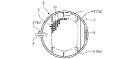
- FIG. 1 shows the entire configuration of the heat exchanger of the present embodiment.
- the heat exchanger 1 is covered with a shell 3 around a heating line 2 for circulating a fluid to be heated L such as LNG inside, and a heat medium A such as antifreeze is supplied into the shell 3 to It is a type called a shell and tube type which exchanges heat between each other.
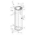
- the heating line 2 is formed, for example, as a heating flow passage group (tube bundle) obtained by bundling a plurality of metal tubes 2 a as flow passages extending along the vertical direction.
- the heating line 2 is disposed so as to penetrate vertically through the central portion of the longitudinally long cylindrical shell 3.
- the heating line 2 has a lower portion as an inlet 2b and an upper portion as an outlet 2c, and the fluid to be heated L is introduced into the heating line 2 from the lower side of the heat exchanger 1 and drawn upward.
- the dashed-dotted line in FIG.2 and FIG.3 has shown the area
- the heat medium A makes a space around the heating line 2 in the shell 3 a flow path.
- the heat medium A is supplied from the supply port 4 opened at two places of the upper part and the lower part of the side surface of the shell 3 and discharged from the exhaust port 5 opened at the middle part of the side surface of the shell 3.
- the heat medium A flowing in the shell 3 exchanges heat while being in contact with the fluid to be heated L flowing through the heating line 2 via the tube 2a.
- a plurality of baffles 6 are provided in order to secure as many opportunities as possible for the heat medium A to exchange heat with the fluid to be heated L flowing in the heating line 2.
- the flow of the heat medium A meanders in the shell 3 while bypassing the baffle plate 6.
- the lower supply port 4a is provided at the lower part of the shell 3 as shown in FIG.
- the heat medium A is supplied into the shell 3 along the horizontal direction in the direction orthogonal to the heating line 2 from the lower supply port 4a.
- the lowermost baffle plate 6a is divided so as to cross the inside of the shell 3 in a plane along the horizontal direction above the lower supply port 4a as shown in FIG. 1 and FIG.
- the lowermost baffle plate 6a is not closed in the vicinity of the lower supply port 4a and the inner wall of the shell 3 opposite to the lower supply port 4a, and there is an opening between the lower supply port 4a and the inner wall.
- baffle plate 6b positioned one step above the baffle plate 6a forms a surface along the horizontal direction above the baffle plate 6a as shown in FIG. 1, the shell 3 is divided, but the lower supply port 4a side An opening is present between the inner wall of the shell 3 and the inner wall of the shell 3.
- baffle plate 6c located on one step of the baffle plate 6b is disposed to cross the upper side of the baffle plate 6b, an opening is formed between the lower supply port 4a and the inner wall of the shell 3 on the opposite side.
- the heat medium A introduced into the shell 3 from the lower supply port 4a first flows horizontally in the vicinity of the bottom surface of the shell 3 and bypasses the baffle plate 6a in the vicinity of the inner wall opposite to the lower supply port 4a. It flows upward while doing it. Furthermore, the heat medium A flows between the baffle plate 6a and the baffle plate 6b toward the lower supply port 4a side along the horizontal direction, and then flows upward while bypassing the baffle plate 6b.
- the heat medium A supplied from the upper supply port 4 b is guided downward while meandering in the shell 3 by the baffle plates 6 alternately arranged in the shell 3 and discharged from the discharge port 5. It has become so.
- having one of the two supply ports 4 (the lower supply port 4a) provided at the lower part of the shell 3 is effective in improving heat exchange efficiency and preventing freezing of the heat medium A in two ways.
- the low temperature heated fluid L is introduced into the heating line 2 from the lower inlet 2b of the shell 3 and is directed to the upper outlet 2c while exchanging heat. Therefore, the heat medium A flowing downward in the shell 3 is in contact with the heated fluid L whose temperature is lower. For this reason, in the case of the heat exchanger 1 of the present embodiment, the heat medium A is supplied from the lower portion of the shell 3 which is the inlet 2 b side with respect to the heating line 2.
- the heat medium A in the state of high temperature is brought into contact with the fluid to be heated L which has been introduced into the heating line 2 and has a low temperature immediately after being supplied to the shell 3.
- the heat medium A in the state of high temperature is brought into contact with the fluid to be heated L which has been introduced into the heating line 2 and has a low temperature immediately after being supplied to the shell 3.
- the heat medium A is supplied from the upper supply port 4b as well as the lower supply port 4a.
- This is a configuration for further heating the to-be-heated fluid L vaporized while passing through the heating line 2. That is, in the case where the fluid to be heated L is, for example, LNG stored at a cryogenic temperature, the temperature may not reach the appropriate temperature even though it is vaporized. For this reason, the heating medium A is also supplied near the outlet 2 c of the heating line 2 to heat up to an appropriate temperature.
- the baffle plate 6 plays a role of simultaneously restraining the tubes 2a constituting the heating line 2 and supporting the shell 3 as well as forming the flow path of the heat medium A as described above.
- Each one of the tubes 2a is thin, and the inside of the shell 3 is extended long in the vertical direction. Therefore, if it is not supported by any means, deformation such as bending is likely to occur. Therefore, as shown in FIG. 2, each tube 2 a is made to penetrate the baffle plate 6 crossing the inside of the shell 3, and the baffle plate 6 is fixed to the shell 3. By doing this, the tube 2a constituting the heating line 2 is supported.
- the baffle plate 6 also has an effect that the distance between the tubes 2a is properly maintained.
- FIGS. 1 to 3 a plurality of seal plates 7 as shown in FIGS. 1 to 3 are provided in the shell 3. By partially blocking the flow of the heat medium A by the seal plate 7, the heat medium A is prevented from flowing away from the heating line 2 in the shell 3.
- the baffle plate 6 and the like are not shown for the sake of convenience of describing the shape of the seal plate 7 and the positional relationship with the heating line 2.
- the tube bundle constituting the heating line 2 is disposed at the center of the shell 3 as described above.
- a layer of the heat medium A of an appropriate thickness is interposed between the low temperature heated fluid L flowing in the heating line 2 and the space outside the shell 3. Then, if the heat medium A is to flow to the heating line 2 if the seal plate 7 as in this embodiment is not disposed here, the flow of the heat medium A deviates from the heating line 2 and the heating line 2 Try to flow through the space outside the
- the heating line 2 is configured as a tube bundle consisting of a large number of tubes 2a as described above. Then, the heat medium A flows between the tubes 2a arranged at a predetermined distance from each other so as to exchange heat with the fluid to be heated L flowing in the tubes 2a. ing.
- the gap between the tubes 2a is narrower than the space between the heating line 2 which is a tube bundle and the inner wall of the shell 3, and the flow path resistance is large. For this reason, without the seal plate 7, most of the heat transfer medium A does not flow between the tubes 2 a and passes between it and the inner wall of the shell 3 outside the heating line 2.
- the seal plate 7 is a plate-like member disposed between the inner wall of the shell 3 and the heating line 2 in order to prevent this.
- the seal plate 7 extends from the inner wall of the shell 3 toward the heating line 2 in a plane along the vertical direction, as shown in FIGS.
- the lower end portion of the seal plate 7 is curved toward the lower supply port 4 a to form a slope portion 7 a described later.
- the surface of each seal plate 7 is orthogonal to the flow of the heat medium A introduced from the supply port 4 or the flow of the heat medium A flowing in the horizontal direction between the baffle plates 6 in a plan view.
- Each sealing plate 7 is integrally welded to the inner wall of the shell 3 at one side extending in the vertical direction, and the other side is located near the heating line 2.
- the other side of the seal plate 7 be disposed at a distance approximately equal to the distance between the tubes 2 a constituting the tube bundle, with respect to the tube bundle which is the heating line 2.
- the flow path resistance in the case of flowing between the tubes 2a and the flow path resistance in the case of flowing between the tube 2a and the seal plate 7 become approximately equal.
- the heat medium A can be uniformly flowed to the respective tubes 2 a constituting the heating line 2. If the gap between the seal plate 7 and the heating line 2 is larger than this, the flow of the heat medium A may be deviated from the heating line 2 as described above, while if it is smaller, the heat medium A may be stagnated here. There is. Also from this point of view, it is preferable to set the distance to the distance between the tubes 2a.
- the heat exchanger 1 of the present embodiment is characterized in that a rectifying plate 8 is provided at the bottom of the shell 3 and the flow of the heat medium A at this position is corrected.
- a rectifying plate 8 is provided at the bottom of the shell 3 and the flow of the heat medium A at this position is corrected.
- the straightening vane 8 is disposed at the bottom of the shell 3 at a position facing the lower supply port 4 a so as to form an upward gradient when viewed from the lower supply port 4 a.
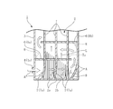
- the flow of the heat medium A fed into the shell 3 from the lower supply port 4a proceeds along the horizontal direction as shown in FIG. 4 and is then bent near the opposite inner wall to turn it at a right angle. Head upwards. At this time, the flow of the heat medium A collides with the current plate 8, whereby the flow of the heat medium A is induced along the surface of the current plate 8 and the flow direction is smoothly changed upward.
- the heat transfer medium A is easily left behind from the flow at the corner of the bottom of the shell 3 that is outside the flow path. Then, if heat exchange is performed with the fluid to be heated L in a state where the heat medium A stays at a predetermined place, the heat medium A may be frozen as a result of continuing to be deprived of heat.
- the bottom of the shell 3 is close to the inlet 2 b of the heating line 2, and a particularly low temperature heated fluid L which has not yet sufficiently exchanged heat with the heating medium A flows. That is, the bottom of the shell 3 is a portion of the shell 3 where the temperature tends to be low.
- the heat exchanger 1 is used as a vaporizer for vaporizing the fluid to be heated L, peripheral heat is rapidly taken away with the vaporization and the temperature is likely to be lowered.
- the heat medium A is supplied from the lower supply port 4 a disposed near the inlet 2 b of the heating line 2 to prevent the heat medium A from freezing.
- the heat medium A containing heat is not newly supplied at that portion, and the temperature of the heat medium A is easily lowered.
- the flow control plate 8 is disposed at this position to correct the flow of the heat medium A, and the retention of the heat medium A is suppressed to prevent freezing in advance. Also, even if freezing occurs partially, the growth is suppressed by the new heat transfer medium A flowing one after another. At the same time, the heat exchange efficiency can be improved by smoothing the flow of the heat medium A.
- the straightening vane 8 has a predetermined curvature from the upstream side direction (here, horizontal direction) of the heat medium A toward the downstream side direction (here, upward direction) for guiding the heat medium A.
- they are arranged in a smoothly curved surface.
- the flow straightening plate 8 can also be configured as a flat plate, and even if it is so, it is considered that it has a certain effect in suppressing the retention of the heat medium A.
- an angle close to a right angle is formed between the straightening vane 8 and the bottom or inner wall of the shell 3, which may cause a stagnation.
- the angle between the straightening vane 8 and the bottom or inner wall of the shell 3 is made as small as possible by forming the straightening vane 8 as a curved plate that curves smoothly in the direction of leading the heat medium A from the upstream side. It is greater than the degree. By doing this, it is possible to smoothly change the direction of the flow of the heat medium A and make it difficult for the heat medium A to stay.
- the lower end portion of the seal plate 7 is curved to form the sloped portion 7a, and the flow of the heat medium A is also rectified by this sloped portion 7a.
- the surface formed by the seal plate 7 is disposed to be orthogonal to the horizontal flow of the heat medium A in plan view.
- the lower end portion of the seal plate 7 is formed as a sloped portion 7a curved toward the lower supply port 4a as shown in FIGS. 3 and 4, and viewed upward from the lower supply port 4a It has the same orientation as the plate 8.
- the heat medium A fed from the lower supply port 4 a is guided upward by the same action as the above-described straightening vane 8. Then, the heat medium A is prevented from staying in the corner portion where the lower end portion of the seal plate 7 and the bottom surface of the shell 3 are in contact with each other, thereby preventing freezing and improving the heat exchange efficiency.
- the flow path configuration of the heat medium A and the installation direction of the straightening vane 8 and the slope portion 7a are not limited to the examples described above.
- the orientations of the straightening vanes 8 and the slope portion 7 a can be variously changed depending on the shape of the flow path in the shell 3 and the like.
- the straightening vanes and the slopes are arranged in a lateral slope when viewed from the supply port.
- the setting of the slopes of the straightening vanes and the slopes should be made in accordance with the flow path configuration of the heat transfer medium in the shell so as to make a gradient toward the heat transfer medium.
- the slope portion 7a of the flow control plate 8 and the seal plate 7 can be provided, for example, around the baffle plate 6a and the baffle plate 6b besides the bottom of the shell 3.
- freezing of the heat medium A is most concerned at the bottom of the shell 3 at the inlet 2 b side of the heating line 2, so stagnation of the heat medium A by the flow straightening plate 8 and the slope portion 7 a at this position Are trying to curb
- the baffles 8 and the slopes 7a are provided at other positions, there is no particular disadvantage.
- the flow straightening plate 8 and the slope portion 7a can be installed appropriately.
- the heat exchanger 1 of the present embodiment includes the heating line 2 for circulating the fluid to be heated L therein, and the shell 3 surrounding the heating line 2, and the heat medium A is contained in the shell 3.
- the shell 3 In the shell 3 to bend the flow of the heat transfer medium A in the shell 3 in the direction of guiding the heat transfer medium A as viewed from the upstream side of the heat transfer medium A.
- a straightening vane 8 is provided to make a slope.
- the shell 3 is provided with the supply port 4 of the heat medium A at the inlet 2b side of the heating line 2, and the flow straightening plate at the position facing the supply port 4 There are eight.
- the heating line 2 is configured to extract the heated fluid L introduced from the lower side upward
- the supply port 4 (the lower supply port 4 a) is of the shell 3. It is provided in the lower part, and the straightening vane 8 is arranged at the bottom of the shell 3 so as to make an upward slope when viewed from the supply port 4 (the lower supply port 4a). By so doing, stagnation can be effectively suppressed in the heat exchanger 1 of the type in which the heated fluid L introduced from the lower side is extracted upward.
- the straightening vane 8 has a surface which is smoothly curved in the direction of leading the heat medium A from the upstream side of the heat medium A. By doing this, it is possible to make it possible to smoothly change the direction of the flow of the heat medium A and make it more difficult for the heat medium A to stay.
- the heating line 2 is configured as a heating flow path group formed by bundling a plurality of flow paths (tubes 2 a), and between the inner wall of the shell 3 and the heating line 2 And a seal plate 7 for blocking the flow of the heat medium A, at least a part of the seal plate 7 is inclined in the direction in which the straightening plate 8 guides the heat medium A when viewed from the upstream side of the heat medium A. It is formed as an inclined portion 7a.
- the heat exchanger of this indication is not limited only to the above-mentioned Example. Needless to say, various changes can be made without departing from the scope of the present disclosure, such as being applicable not only to vaporization of liquefied natural gas but also to heating of liquefied ethylene and the like.
- heat exchanger heating line (heating flow path group) 2a channel (tube) 2b Inlet 3 Shell 4 Supply port 4a Supply port (lower supply port) 7 seal plate 7a gradient section 8 straightening plate A heat medium (antifreeze) L Heated fluid (Liquefied natural gas)
Landscapes
- Engineering & Computer Science (AREA)
- Mechanical Engineering (AREA)
- General Engineering & Computer Science (AREA)
- Physics & Mathematics (AREA)
- Thermal Sciences (AREA)
- Heat-Exchange Devices With Radiators And Conduit Assemblies (AREA)
- Filling Or Discharging Of Gas Storage Vessels (AREA)
Abstract
熱交換器1は、内部に被加熱流体Lを流通させる加熱ライン2と、該加熱ライン2を包囲するシェル3を備え、該シェル3内に熱媒体Aを供給して被加熱流体Lと熱交換させるよう構成され、シェル3内で熱媒体Aの流れを屈曲させる位置に、熱媒体Aの上流側から見て熱媒体Aを導く方向へ向かって勾配をなす整流板8を配する。加熱ライン2は下方から導入した被加熱流体Lを上方へ抜き出すよう構成し、供給口4(下部供給口4a)はシェル3の下部に備え、整流板8はシェル3の底部に供給口4(下部供給口4a)から見て上り勾配をなすよう配置する。
Description
本開示は、液化天然ガス等の流体を加熱するための熱交換器に関する。
一般に、液化天然ガス(LNG)を燃料として利用する際には、低温で貯蔵されたLNGを加熱して気化させる必要がある。この際、LNGの加熱には、空気や水といった流体を熱源として利用するオープンラック式の熱交換器や、別の熱源からの熱を熱媒体の循環によりLNGに伝達する中間媒体式の熱交換器等、種々の型式の熱交換器が用いられている。
このうち、中間媒体式の熱交換器では、極低温のLNGと熱媒体とを熱交換させるため、熱媒体の凍結を極力防止する必要がある。熱媒体が凍結し、循環流路が閉塞されると、熱交換効率が低下するからである。そこで、熱媒体としては、例えばプロパンやブタン等のLPGや、あるいはエチレングリコールやプロピレングリコールを主成分とする不凍液等、凍結しにくい流体が用いられることが多い。
熱媒体として不凍液を採用した熱交換器に関する技術文献としては、例えば、下記の特許文献1等がある。
エチレングリコールやプロピレングリコールを用いた不凍液には、プロパンやブタンと比較して発火しにくく、安全性が高いという利点がある一方、凝固点が高く凍結しやすい問題がある。このため、特許文献1に記載されている熱交換器(LNGベーパライザ)では、胴部を下部の第1熱交換部とその上部の第2熱交換部、さらにその上部の第3熱交換部の3つの熱交換部に分割し、それぞれに対して供給する不凍液の流量を不凍液流量制御装置で制御するようにしている。こうすることで、鉛直伝熱管におけるLNGの入口付近に位置し特に低温になりやすい第1熱交換部における不凍液の温度を凍結温度より十分高く維持し、不凍液の凍結防止を図るようにしている。
しかしながら、特許文献1に記載の如き熱交換器では、3つの熱交換部それぞれについて不凍液の流路を形成する必要がある。また、各流路について流量制御のための弁等を装備しなくてはならず、装置全体が複雑となって建造コストが嵩む上、頻繁且つ煩雑なメンテナンス作業を要する問題があった。
尚、ここではLNGを気化させるための熱交換器を例に説明したが、LNGに限らず流体一般を加熱するための熱交換器について、同様の問題は広く存在し得る。例えば、化学プラント等において液化エチレンを気化するために用いられる熱交換器等でも事情は同じである。
本開示は、斯かる実情に鑑み、簡単な構成で好適に熱媒体の凍結を防止し得る熱交換器を提供しようとするものである。
本開示は、内部に被加熱流体を流通させる加熱ラインと、該加熱ラインを包囲するシェルを備え、該シェル内に熱媒体を供給して被加熱流体と熱交換させるよう構成され、前記シェル内で熱媒体の流れを屈曲させる位置に、熱媒体の上流側から見て熱媒体を導く方向へ向かって勾配をなす整流板を配した熱交換器にかかるものである。
本開示の熱交換器においては、前記シェルにおける前記加熱ラインの入口側の位置に熱媒体の供給口を備え、該供給口と対向する位置に前記整流板を配することが好ましい。
本開示の熱交換器において、前記加熱ラインは、下方から導入した被加熱流体を上方へ抜き出すよう構成され、前記供給口は、前記シェルの下部に備えられ、前記整流板は、前記シェルの底部に前記供給口から見て上り勾配をなすよう配置されていることが好ましい。
本開示の熱交換器において、前記整流板は、熱媒体の上流側から熱媒体を導く方向へ向かって滑らかに湾曲する面をなして構成されることが好ましい。
本開示の熱交換器においては、前記加熱ラインは、複数の流路を束ねた加熱流路群として構成され、前記シェルの内壁と前記加熱ラインの間に、熱媒体の流れを遮るシール板を備え、該シール板の少なくとも一部は、熱媒体の上流側から見て前記整流板が熱媒体を導く方向へ向かって勾配をなす勾配部として形成されていることが好ましい。
本開示の熱交換器によれば、簡単な構成で好適に熱媒体の凍結を防止し得るという優れた効果を奏し得る。
以下、本発明の実施の形態を添付図面を参照して説明する。
図1~図4は本発明の実施形態に係る熱交換器の形態の一例を示している。図1は本実施例の熱交換器の全体構成を示している。熱交換器1は、内部にLNG等の被加熱流体Lを流通させる加熱ライン2の周囲をシェル3で覆い、該シェル3内に不凍液等の熱媒体Aを供給して被加熱流体Lとの間で熱交換させるシェルアンドチューブ型と呼ばれる型式である。
加熱ライン2は、例えば鉛直方向に沿って延びる流路としての複数の金属製のチューブ2aを束ねた加熱流路群(チューブバンドル)として形成されている。加熱ライン2は、縦長の円筒形状をなすシェル3の中心部を上下に貫通するように配置されている。加熱ライン2は、下部を入口2b、上部を出口2cとし、被加熱流体Lは、熱交換器1の下方から加熱ライン2に導入されて上方へ抜き出されるようになっている。尚、図2及び図3中の一点鎖線は、チューブ2aが束となって配置されている領域を示している。
熱媒体Aはシェル3内において加熱ライン2周囲の空間を流路とする。本実施例の場合、熱媒体Aは、シェル3側面の上部と下部の二箇所に開口した供給口4から供給されて、シェル3側面の中間部に開口した排出口5から排出される。こうして、シェル3内を流れる熱媒体Aは、加熱ライン2を流通する被加熱流体Lとチューブ2aを介して接触しながら熱交換するようになっている。シェル3内には、熱媒体Aが加熱ライン2内を流通する被加熱流体Lと熱交換する機会をなるべく多く確保するために複数枚の邪魔板6が設置されている。熱媒体Aの流れはこの邪魔板6を迂回しながらシェル3内を蛇行するようになっている。
下部供給口4aは、図1に示す如くシェル3の下部に備えられている。熱媒体Aは、下部供給口4aから加熱ライン2に対して直交する向きに、水平方向に沿ってシェル3内へ供給される。邪魔板6のうち、最下段の邪魔板6aは、図1、図2に示す如く下部供給口4aの上方において水平方向に沿った面をなしてシェル3内を横断するように区切っている。この最下段の邪魔板6aは下部供給口4aと反対側のシェル3の内壁付近は閉塞しておらず、該内壁との間に開口が存在している。また、邪魔板6aの一段上に位置する邪魔板6bは、図1に示す如く邪魔板6aの上方において水平方向に沿った面をなしてシェル3を区切っているが、下部供給口4a側のシェル3の内壁との間には開口が存在している。さらに、邪魔板6bの一段上に位置する邪魔板6cは、邪魔板6bの上方を横断するように配置されているが、下部供給口4aと反対側のシェル3の内壁との間に開口が存在している。
したがって、下部供給口4aからシェル3内に導入された熱媒体Aは、まずシェル3の底面付近を水平方向に沿って流れ、下部供給口4aと反対側の内壁付近にて邪魔板6aを迂回しつつ上方へ流れる。さらに、熱媒体Aは、邪魔板6aと邪魔板6bの間を下部供給口4a側に向かい水平方向に沿って流れた後、邪魔板6bを迂回しつつ上方へ流れていく。
このようにして、シェル3内に邪魔板6を熱媒体Aの流路に対し互い違いに配することにより、下部供給口4aから導入された熱媒体Aをシェル3内で蛇行させつつ排出口5へと導くようになっている。
また、上部供給口4bから供給される熱媒体Aについても、同様にシェル3内に互い違いに配置された邪魔板6により、シェル3内を蛇行しつつ下方へ導かれ、排出口5から排出されるようになっている。
ここで、二個の供給口4のうち一方(下部供給口4a)がシェル3の下部に備えられていることは、熱交換効率の向上と熱媒体Aの凍結防止の二点において有効である。上述の如く、低温の被加熱流体Lはシェル3の下側の入口2bから加熱ライン2へ導入され、熱交換しながら上方の出口2cへ向かうようになっている。よって、シェル3内の下方を流れる熱媒体Aほど温度の低い被加熱流体Lと接することになる。このため、本実施例の熱交換器1の場合、加熱ライン2に関して入口2b側であるシェル3の下部から熱媒体Aを供給するようにしている。こうすることで、加熱ライン2へ導入されて間がなく温度が低い状態の被加熱流体Lに、シェル3へ供給した直後で温度が高い状態の熱媒体Aを接触させるようにしている。こうして、効率の良い熱交換を図ると同時に熱媒体Aの凍結をなるべく防止するようにしている。
また、本実施例の場合、下部供給口4aのほか、上部供給口4bからも熱媒体Aを供給するようにしている。これは、加熱ライン2を通過する間に気化した被加熱流体Lをさらに加温するための構成である。すなわち、被加熱流体Lが例えば極低温にて貯蔵されたLNGである場合、気化してはいても未だ温度が適温に満たないことがある。このため、加熱ライン2の出口2c付近にも熱媒体Aを供給することで、適温まで加温するようにしている。
邪魔板6は、上述の如き熱媒体Aの流路形成のほか、加熱ライン2を構成するチューブ2a同士を拘束し、シェル3に対して支持する役割をも同時に果たしている。チューブ2aの一本一本は細く、且つシェル3の内部を上下に長く延設されている。このため、何らかの手段により支持しなければ撓み等の変形を生じやすい。そこで、シェル3内を横断する邪魔板6に、図2に示す如く各チューブ2aを貫通させ、且つ邪魔板6をシェル3に対して固定している。こうすることで、加熱ライン2を構成するチューブ2aを支持するようにしている。また、邪魔板6により、チューブ2a同士の間隔も適正に保たれるという作用もある。すなわち、シェル3に対して加熱ライン2を組み付ける際には、例えば、まず複数の邪魔板6に穴を所定の間隔で開口する。そして、該穴にチューブ2aを通して固定することでチューブバンドルを形成する。そして、該チューブバンドルを邪魔板6ごとシェル3に収容し、邪魔板6をシェル3の内壁に溶接等により固定する。このようにすれば、邪魔板6に開口した前記穴によってチューブ2a同士の間隔を簡単且つ確実に規定することができる。また、チューブ2a間の流路面積を等しくして熱交換効率の均質化を図ることができる。
さらに、シェル3内には図1~図3に示す如き複数のシール板7が備えられている。このシール板7により熱媒体Aの流れを部分的に遮ることで、シェル3内において熱媒体Aが加熱ライン2を逸れて流れることを防止するようになっている。尚、図3ではシール板7の形状や加熱ライン2との位置関係を説明する便宜上、邪魔板6等については図示を省略している。
加熱ライン2を構成するチューブバンドルは、上述の如くシェル3の中心部に配置されている。これにより、加熱ライン2内を流通する低温の被加熱流体Lと、シェル3の外部の空間との間に適当な厚さの熱媒体Aの層を介在させるようになっている。そして、仮にここに本実施例の如きシール板7が配置されていなければ、加熱ライン2に対して熱媒体Aを流そうとすると、熱媒体Aの流れは加熱ライン2を逸れて加熱ライン2の外側の空間を流れようとする。
すなわち、加熱ライン2は上述の如く多数のチューブ2aからなるチューブバンドルとして構成されている。そして、互いに所定の間隔を有して離間配置されたチューブ2a同士の間を熱媒体Aが流れることにより、チューブ2a内を流通する被加熱流体Lとの間で熱交換が行われるようになっている。そして、このチューブ2a同士の間の隙間は、チューブバンドルである加熱ライン2と、シェル3の内壁との間の空間より狭く、流路抵抗が大きい。このため、シール板7がなければ、熱媒体Aの多くはチューブ2a同士の間を流れることなく、加熱ライン2外側のシェル3の内壁との間を通過していってしまう。シール板7はこれを防止するため、シェル3の内壁と加熱ライン2との間に配置された板状の部材である。
シール板7は、図2、図3に示す如く、シェル3の内壁から加熱ライン2に向かって鉛直方向に沿った面をなして延設されている。シール板7の下端部は、下部供給口4aに向かって湾曲して後述の勾配部7aを形成している。各シール板7のなす面は、供給口4から導入される熱媒体Aの流れ、ないし各邪魔板6の間を水平方向に流れる熱媒体Aの流れに平面視で直交している。
各シール板7は、上下方向に延びる面の一側がシェル3の内壁に一体的に溶接されており、他側は加熱ライン2の近傍に位置している。このようにシール板7を配置すれば、各邪魔板6の間を熱媒体Aが水平方向に沿って流れる際(図1参照)、加熱ライン2の外側を流れようとしてもシール板7に遮られる。このため、熱媒体Aは、強制的に加熱ライン2を構成するチューブ2aの隙間に流れ込むことになる。
ここで、シール板7の他側は、加熱ライン2であるチューブバンドルに対し、該チューブバンドルを構成するチューブ2a同士の間隔と同程度の間隔を置いて配置することが好適である。このようにすれば、チューブ2a同士の間を流れる場合の流路抵抗と、チューブ2aとシール板7の間を流れる場合の流路抵抗がおおむね等しくなる。その結果、加熱ライン2を構成する各チューブ2aに対して均等に熱媒体Aを流すことが可能となる。また、シール板7と加熱ライン2との間の隙間は、これより大きいと上述の如く熱媒体Aの流れが加熱ライン2から逸れる問題が生じる一方、小さいと熱媒体Aがここで滞留する虞がある。この点からも、やはりチューブ2a同士の間隔と同程度とすることが好ましい。
そして、本実施例の熱交換器1は、シェル3底部に整流板8を備え、この位置における熱媒体Aの流れを是正するよう構成した点に特徴がある。以下、この整流板8の構成及び作用について、図1、図3及び図4を参照しながら説明する。
図1、図3に示す如く、整流板8は、シェル3の底部における下部供給口4aと対向する位置に、該下部供給口4aから見て上向きの勾配をなすよう配置されている。
下部供給口4aからシェル3内に送り込まれた熱媒体Aの流れは、図4に示す如く、水平方向に沿って進んだ後、反対側の内壁付近にて屈曲させられ、直角に方向転換して上方へ向かう。この際、熱媒体Aの流れが整流板8に衝突することにより、熱媒体Aの流れは該整流板8のなす面に沿って誘導され、滑らかに流れの向きを上向きに変更される。
ここで、整流板8が設置されていない場合を仮定すると、熱媒体Aの方向転換に際し、その流路の外側にあたるシェル3底部の隅に熱媒体Aが流れから取り残されて滞留しやすい。そして、熱媒体Aが一定の場所に滞留した状態で被加熱流体Lと熱交換すれば、熱媒体Aは熱を奪われ続けた結果、凍結を生じてしまう虞がある。しかも、シェル3の底部は加熱ライン2の入口2bに近く、未だ熱媒体Aと十分に熱交換していない、特に低温の被加熱流体Lが流通している。すなわち、シェル3の底部は、シェル3の中でも温度が低くなりやすい部分である。とりわけ、熱交換器1が被加熱流体Lを気化させる気化器として使用される場合には、気化に伴い周辺の熱が急速に奪われ、温度が低下しやすい。
無論、本実施例においては、上述の如く、熱媒体Aを加熱ライン2の入口2b近くに配置した下部供給口4aから供給することで、熱媒体Aの凍結防止を図っている。しかしながら、熱媒体Aに滞留が生じてしまえば、その部分では熱を含んだ熱媒体Aが新しく供給されないことになり、熱媒体Aの温度は容易に低下してしまう。そして、熱媒体Aは一部が凍結すると、その結晶が成長して周囲にまで凍結が波及してしまう虞がある。そこで、本実施例ではこの位置に整流板8を配置して熱媒体Aの流れを是正し、熱媒体Aの滞留を抑えて凍結を未然に防止している。また、万一、部分的に凍結が発生したとしても、新しい熱媒体Aが次々に流れてくることで、その成長が抑えられるようにしているのである。同時に、熱媒体Aの流れを円滑にすることで熱交換効率をも向上し得るようになっている。
この際、整流板8は、熱媒体Aの上流側の向き(ここでは、水平方向)から、熱媒体Aを導く下流側の向き(ここでは、上方向)に向かって、所定の曲率を有して滑らかに湾曲する面をなして配置されていることが好ましい。勿論、整流板8は平面状の板として構成することも可能であり、そうであっても熱媒体Aの滞留を抑える上で一定の効果を有すると考えられる。しかしながら、そうした場合、整流板8とシェル3の底部あるいは内壁との間に直角に近い角が形成されてしまい、滞留の要因となり得る。そこで、整流板8を上流側から熱媒体Aを導く方向へ向かって滑らかに湾曲する曲面をなす板として形成することにより、整流板8とシェル3の底部ないし内壁との間の角度をなるべく90度より大きくしている。こうすることで、熱媒体Aの流れのスムーズな方向転換を可能にして熱媒体Aを滞留しにくくしている。
さらに、本実施例の場合、シール板7の下端部を湾曲させて勾配部7aを形成し、この勾配部7aによっても熱媒体Aの流れを整流するようになっている。
シール板7の形成する面は、上述の如く熱媒体Aの水平方向の流れと平面視で直交するように配置されている。本実施例の場合、シール板7の下端部は図3、図4に示す如く下部供給口4aに向かって湾曲した勾配部7aとして形成されており、下部供給口4aから見て上向きに、整流板8と同じ向きの勾配をなしている。こうすることで、上述の整流板8と同様の作用により、下部供給口4aから送り込まれる熱媒体Aを上方へ導くようにしている。そして、シール板7の下端部とシェル3の底面が接する隅の部分にて熱媒体Aが滞留することを抑制し、凍結の防止と熱交換効率の向上を図っている。
ここで、熱媒体Aの流路構成や、整流板8及び勾配部7aの設置の向きは、上で説明した例に限定されない。整流板8や勾配部7aの向きは、シェル3における流路の形状等によって種々変更され得る。例えば、熱交換器の用途その他の条件によっては、シェルの下方から供給した熱媒体を上方へ流した後、横向きに方向転換させるといった流路構成も想定できる。その場合には、整流板や勾配部は供給口から見て横向きの勾配をなして配置される。このように、整流板や勾配部の勾配の設定は、熱媒体を導く方向へ向かう勾配をなすよう、シェル内における熱媒体の流路構成に応じてなされるべきである。
また、図4に破線で示す如く、整流板8やシール板7の勾配部7aは、シェル3の底部以外にも、例えば邪魔板6aや邪魔板6bの周辺に備えることも可能である。本実施例では上述の如く、加熱ライン2の入口2b側にあたるシェル3の底部において熱媒体Aの凍結が最も懸念されるので、この位置にて整流板8や勾配部7aにより熱媒体Aの滞留の抑制を図っている。しかしながら、その他の位置に整流板8や勾配部7aを備えても特段の不都合があるわけではない。シェル3の底部以外に、例えば邪魔板6aの付近においても熱媒体Aの凍結を防止したいといった事情がある場合には、適宜整流板8や勾配部7aを設置することができる。
以上のように、上記本実施例の熱交換器1は、内部に被加熱流体Lを流通させる加熱ライン2と、該加熱ライン2を包囲するシェル3を備え、該シェル3内に熱媒体Aを供給して被加熱流体Lと熱交換させるよう構成され、前記シェル3内で熱媒体Aの流れを屈曲させる位置に、熱媒体Aの上流側から見て熱媒体Aを導く方向へ向かって勾配をなす整流板8を配している。こうすることで、該整流板8のなす面に沿って熱媒体Aの流れを誘導することで、熱媒体Aの流れを円滑化し、滞留を抑えることができる。
また、本実施例の熱交換器1においては、前記シェル3における前記加熱ライン2の入口2b側の位置に熱媒体Aの供給口4を備え、該供給口4と対向する位置に前記整流板8を配している。こうすることで、熱媒体Aが特に低温の被加熱流体Lに接する位置において熱媒体Aの滞留を抑え、凍結を防止すると共に熱交換効率を向上させることができる。
また、本実施例の熱交換器1において、前記加熱ライン2は、下方から導入した被加熱流体Lを上方へ抜き出すよう構成され、前記供給口4(下部供給口4a)は、前記シェル3の下部に備えられ、前記整流板8は、前記シェル3の底部に前記供給口4(下部供給口4a)から見て上り勾配をなすよう配置されている。こうすることで、下方から導入した被加熱流体Lを上方へ抜き出す型式の熱交換器1において滞留を効果的に抑制することができる。
また、本実施例の熱交換器1において、前記整流板8は、熱媒体Aの上流側から熱媒体Aを導く方向へ向かって滑らかに湾曲する面をなして構成される。こうすることで、熱媒体Aの流れのスムーズな方向転換を可能にして熱媒体Aを一層滞留しにくくすることができる。
また、本実施例の熱交換器1においては、前記加熱ライン2は、複数の流路(チューブ2a)を束ねた加熱流路群として構成され、前記シェル3の内壁と前記加熱ライン2の間に、熱媒体Aの流れを遮るシール板7を備え、該シール板7の少なくとも一部は、熱媒体Aの上流側から見て前記整流板8が熱媒体Aを導く方向へ向かって勾配をなす勾配部7aとして形成されている。こうすることで、整流板8の設置に加え、シェル3内に備えたシール板7の形状に変更を加えることで、熱媒体Aの滞留を防止することができる。
したがって、上記本実施例によれば、簡単な構成で好適に熱媒体の凍結を防止し得る。
尚、本開示の熱交換器は、上述の実施例にのみ限定されるものではない。例えば液化天然ガスの気化だけでなく液化エチレンの加熱等にも適用し得ること等、本開示の要旨を逸脱しない範囲内において種々変更を加え得ることは勿論である。
1 熱交換器
2 加熱ライン(加熱流路群)
2a 流路(チューブ)
2b 入口
3 シェル
4 供給口
4a 供給口(下部供給口)
7 シール板
7a 勾配部
8 整流板
A 熱媒体(不凍液)
L 被加熱流体(液化天然ガス)
2 加熱ライン(加熱流路群)
2a 流路(チューブ)
2b 入口
3 シェル
4 供給口
4a 供給口(下部供給口)
7 シール板
7a 勾配部
8 整流板
A 熱媒体(不凍液)
L 被加熱流体(液化天然ガス)
Claims (7)
- 内部に被加熱流体を流通させる加熱ラインと、該加熱ラインを包囲するシェルを備え、該シェル内に熱媒体を供給して被加熱流体と熱交換させるよう構成され、
前記シェル内で熱媒体の流れを屈曲させる位置に、熱媒体の上流側から見て熱媒体を導く方向へ向かって勾配をなす整流板を配した熱交換器。 - 前記整流板は、熱媒体の上流側から熱媒体を導く方向へ向かって滑らかに湾曲する面をなして構成される、請求項1に記載の熱交換器。
- 前記シェルにおける前記加熱ラインの入口側の位置に熱媒体の供給口を備え、該供給口と対向する位置に前記整流板を配した請求項1に記載の熱交換器。
- 前記整流板は、熱媒体の上流側から熱媒体を導く方向へ向かって滑らかに湾曲する面をなして構成される、請求項2に記載の熱交換器。
- 前記加熱ラインは、下方から導入した被加熱流体を上方へ抜き出すよう構成され、
前記供給口は、前記シェルの下部に備えられ、
前記整流板は、前記シェルの底部に前記供給口から見て上り勾配をなすよう配置されている、請求項2に記載の熱交換器。 - 前記整流板は、熱媒体の上流側から熱媒体を導く方向へ向かって滑らかに湾曲する面をなして構成される、請求項5に記載の熱交換器。
- 前記加熱ラインは、複数の流路を束ねた加熱流路群として構成され、前記シェルの内壁と前記加熱ラインの間に、熱媒体の流れを遮るシール板を備え、該シール板の少なくとも一部は、熱媒体の上流側から見て前記整流板が熱媒体を導く方向へ向かって勾配をなす勾配部として形成されている、請求項1~6のいずれか一項に記載の熱交換器。
Applications Claiming Priority (2)
| Application Number | Priority Date | Filing Date | Title |
|---|---|---|---|
| JP2016-174389 | 2016-09-07 | ||
| JP2016174389A JP6764734B2 (ja) | 2016-09-07 | 2016-09-07 | 熱交換器 |
Publications (1)
| Publication Number | Publication Date |
|---|---|
| WO2018047786A1 true WO2018047786A1 (ja) | 2018-03-15 |
Family
ID=61562875
Family Applications (1)
| Application Number | Title | Priority Date | Filing Date |
|---|---|---|---|
| PCT/JP2017/031849 Ceased WO2018047786A1 (ja) | 2016-09-07 | 2017-09-04 | 熱交換器 |
Country Status (2)
| Country | Link |
|---|---|
| JP (1) | JP6764734B2 (ja) |
| WO (1) | WO2018047786A1 (ja) |
Families Citing this family (5)
| Publication number | Priority date | Publication date | Assignee | Title |
|---|---|---|---|---|
| CN109140481B (zh) * | 2018-08-09 | 2020-11-17 | 湖南安淳高新技术有限公司 | 高温反应气余热回收装置 |
| CN111678370B (zh) * | 2020-06-17 | 2021-06-01 | 中国航空发动机研究院 | 一种防凝固的换热器 |
| KR102595307B1 (ko) * | 2023-04-03 | 2023-10-30 | 주식회사 삼정이엔씨 | 액화수소 열교환기 |
| JP2025149405A (ja) * | 2024-03-26 | 2025-10-08 | 川崎重工業株式会社 | 極低温用圧縮設備、及びそれを備えるボイルオフガス液化システム |
| KR102877976B1 (ko) * | 2024-09-05 | 2025-10-28 | 나민수 | 튜브시트모듈의 분해 및 청소가 용이한 열교환장치 |
Citations (6)
| Publication number | Priority date | Publication date | Assignee | Title |
|---|---|---|---|---|
| JPS5812060Y2 (ja) * | 1977-07-30 | 1983-03-07 | 株式会社トキメック | 熱交換器 |
| JPS613999A (ja) * | 1984-06-19 | 1986-01-09 | Mitsubishi Heavy Ind Ltd | シエルアンドチユ−ブ型熱交換器 |
| JPH02109182U (ja) * | 1989-01-30 | 1990-08-30 | ||
| JPH06257982A (ja) * | 1993-03-04 | 1994-09-16 | Tokyo Radiator Seizo Kk | 積層型熱交換器 |
| JPH1183382A (ja) * | 1997-09-11 | 1999-03-26 | Hitachi Ltd | シェルアンドチューブ式熱交換器およびそれを用いた冷凍機 |
| JP2006510471A (ja) * | 2002-12-12 | 2006-03-30 | マン、デーヴェーエー、ゲーエムベーハー | 触媒気相反応のためのジャケット管反応装置 |
Family Cites Families (2)
| Publication number | Priority date | Publication date | Assignee | Title |
|---|---|---|---|---|
| JP4164799B2 (ja) * | 2002-11-28 | 2008-10-15 | 株式会社ティラド | Egrクーラ |
| JP2008008568A (ja) * | 2006-06-30 | 2008-01-17 | Isuzu Motors Ltd | 熱交換器 |
-
2016
- 2016-09-07 JP JP2016174389A patent/JP6764734B2/ja active Active
-
2017
- 2017-09-04 WO PCT/JP2017/031849 patent/WO2018047786A1/ja not_active Ceased
Patent Citations (6)
| Publication number | Priority date | Publication date | Assignee | Title |
|---|---|---|---|---|
| JPS5812060Y2 (ja) * | 1977-07-30 | 1983-03-07 | 株式会社トキメック | 熱交換器 |
| JPS613999A (ja) * | 1984-06-19 | 1986-01-09 | Mitsubishi Heavy Ind Ltd | シエルアンドチユ−ブ型熱交換器 |
| JPH02109182U (ja) * | 1989-01-30 | 1990-08-30 | ||
| JPH06257982A (ja) * | 1993-03-04 | 1994-09-16 | Tokyo Radiator Seizo Kk | 積層型熱交換器 |
| JPH1183382A (ja) * | 1997-09-11 | 1999-03-26 | Hitachi Ltd | シェルアンドチューブ式熱交換器およびそれを用いた冷凍機 |
| JP2006510471A (ja) * | 2002-12-12 | 2006-03-30 | マン、デーヴェーエー、ゲーエムベーハー | 触媒気相反応のためのジャケット管反応装置 |
Also Published As
| Publication number | Publication date |
|---|---|
| JP2018040531A (ja) | 2018-03-15 |
| JP6764734B2 (ja) | 2020-10-07 |
Similar Documents
| Publication | Publication Date | Title |
|---|---|---|
| WO2018047786A1 (ja) | 熱交換器 | |
| KR101959657B1 (ko) | 냉매 열교환기 | |
| US20070289559A1 (en) | Heat exchanger, water heater and water tube | |
| JP5156929B2 (ja) | 低温流体の加熱・気化装置およびその運転方法 | |
| KR102262754B1 (ko) | 저온 액화 가스 기화기, 냉각 시스템 및 기화기에 있어서의 착빙 억제 방법 | |
| US10907905B2 (en) | Plate for heat exchange arrangement and heat exchange arrangement | |
| ES2906841T3 (es) | Intercambiador de calor de efluentes de alimentación | |
| JP2008231929A (ja) | Egrクーラ用熱交換器の冷却水入口構造 | |
| WO2019188676A1 (ja) | 中間媒体式気化器 | |
| KR100873092B1 (ko) | 선박용 연료 가열장치 | |
| JP7242481B2 (ja) | 気化装置 | |
| EP4067800B1 (en) | HEAT EXCHANGER | |
| KR102084549B1 (ko) | 가스 기화기 | |
| BR102015030843B1 (pt) | sistema de resfriamento brusco | |
| JP6454628B2 (ja) | 中間媒体式ガス気化器 | |
| US11448468B2 (en) | Plate for heat exchange arrangement and heat exchange arrangement | |
| EP3842724B1 (en) | Heat exchanger and heat exchange system including the same | |
| US20150308387A1 (en) | Gas heat exchanger, in particular for exhaust gases of an engine | |
| JP2008232451A (ja) | 熱交換器の冷却水入口構造 | |
| KR102010156B1 (ko) | 쉘앤플레이트 열교환기용 쉘 및 이를 구비한 쉘앤플레이트 열교환기 | |
| CN105222617B (zh) | 一种用于自然循环系统的低流阻换热器 | |
| JP2012132574A (ja) | 低温液体の気化装置 | |
| KR20170096579A (ko) | 열교환장치 | |
| JP4933125B2 (ja) | シェルアンドチューブ形熱交換器 | |
| CN115516271B (zh) | 换热器 |
Legal Events
| Date | Code | Title | Description |
|---|---|---|---|
| DPE1 | Request for preliminary examination filed after expiration of 19th month from priority date (pct application filed from 20040101) | ||
| 121 | Ep: the epo has been informed by wipo that ep was designated in this application |
Ref document number: 17848726 Country of ref document: EP Kind code of ref document: A1 |
|
| NENP | Non-entry into the national phase |
Ref country code: DE |
|
| 122 | Ep: pct application non-entry in european phase |
Ref document number: 17848726 Country of ref document: EP Kind code of ref document: A1 |