WO2018047718A1 - 異方性歪みセンサシート及び衣類 - Google Patents
異方性歪みセンサシート及び衣類 Download PDFInfo
- Publication number
- WO2018047718A1 WO2018047718A1 PCT/JP2017/031467 JP2017031467W WO2018047718A1 WO 2018047718 A1 WO2018047718 A1 WO 2018047718A1 JP 2017031467 W JP2017031467 W JP 2017031467W WO 2018047718 A1 WO2018047718 A1 WO 2018047718A1
- Authority
- WO
- WIPO (PCT)
- Prior art keywords
- yarn
- strain sensor
- cnt
- sensor sheet
- anisotropic strain
- Prior art date
- Legal status (The legal status is an assumption and is not a legal conclusion. Google has not performed a legal analysis and makes no representation as to the accuracy of the status listed.)
- Ceased
Links
Images
Classifications
-
- G—PHYSICS
- G01—MEASURING; TESTING
- G01B—MEASURING LENGTH, THICKNESS OR SIMILAR LINEAR DIMENSIONS; MEASURING ANGLES; MEASURING AREAS; MEASURING IRREGULARITIES OF SURFACES OR CONTOURS
- G01B7/00—Measuring arrangements characterised by the use of electric or magnetic techniques
- G01B7/16—Measuring arrangements characterised by the use of electric or magnetic techniques for measuring the deformation in a solid, e.g. by resistance strain gauge
Definitions
- the present invention relates to an anisotropic strain sensor sheet and clothing.
- a sensor As such a strain sensor, a sensor is proposed in which a resistor containing a conductive polymer and a binder resin is laminated on the surface of a substrate such as a cloth, and a change in resistance value due to expansion and contraction of the resistor is measured.
- the strain sensor described in this publication is said to be able to be incorporated into clothing or the like, but since a resin resistor is laminated on the surface of the base material, the initial tensile resistance of the portion having the resistor (apparent Young) Rate) may be reduced and the subject may feel uncomfortable, and the breathability of the portion having the resistor may be reduced, which may cause stuffiness.
- strain sensor described in the above publication cannot detect only expansion and contraction in a specific direction because the sheet-like resistor is isotropic.
- the present invention provides an anisotropic strain sensor sheet that is less uncomfortable even when applied to clothing and the like and that can selectively detect expansion and contraction in a specific direction, and clothing that can detect the movement of a human body. This is the issue.
- the invention made in order to solve the above-mentioned problems comprises a plurality of first direction yarns and a plurality of second direction yarns woven, wherein the plurality of first direction yarns is smaller than the plurality of second direction yarns.
- the anisotropic strain sensor sheet includes CNT yarns (yarns formed from carbon nanotube fibers) that have a degree of resistance and the resistance values of the plurality of first direction yarns change by stretching in the longitudinal direction.
- the second direction yarn is preferably a non-twisted yarn.
- the second direction yarn may be a braided yarn.
- the first direction yarn other than the CNT yarn may be a twisted yarn.
- the CNT yarn may have a resin coating layer on the outermost surface.
- a plurality of CNTs constituting the CNT yarn are separated from each other at an intersection position of the CNT yarn and the second resistance yarn.
- Another invention made to solve the above-described problems is a garment in which at least a part of the fabric is the anisotropic conductive sheet.
- the “initial tensile resistance” is a value measured according to JIS-L1013 (2010).
- the “braided thread” means a thread-like body having a configuration (Braided construction) in which a plurality of fibers are knitted without twisting.
- the anisotropic strain sensor sheet of the present invention has a texture almost the same as that of a general woven fabric because the woven yarn includes CNT yarn, and even if used as a fabric constituting at least a part of clothing, It is difficult to give a sense of incongruity. Further, the anisotropic strain sensor sheet can selectively detect only the expansion and contraction in the direction along the first direction yarn by the CNT yarn. For this reason, the clothing of the present invention using the anisotropic strain sensor sheet as at least a part of the fabric can detect the movement of the human body.
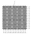
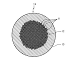
- FIG. 2 is a schematic cross-sectional view illustrating the configuration of CNT yarns of the anisotropic strain sensor sheet in FIG. 1.
- the anisotropic strain sensor sheet according to the first embodiment of the present invention shown in FIG. 1 includes a plurality of first direction yarns 1 and a plurality of second direction yarns 2 woven. That is, the anisotropic strain sensor sheet has a woven fabric in which one of the first direction yarn 1 and the plurality of second direction yarns 2 is a warp and the other of the first direction yarn 1 and the plurality of second direction yarns 2 is a weft. Formed from cloth.
- the way of weaving the first direction yarn 1 and the plurality of second direction yarns 2 is not particularly limited, and for example, a plain weave, a twill weave, a satin weave, or the like can be used.
- the plurality of first direction yarns 1 include CNT yarns 1a whose resistance values change due to expansion and contraction in the longitudinal direction. That is, the one or more first direction yarns 1 are composed of the CNT yarns 1a. Further, the first direction yarn 1 can include a yarn (hereinafter sometimes referred to as a normal yarn) 1b other than the CNT yarn 1a.
- the first direction yarn 1 since the first direction yarn 1 includes the CNT yarn whose strength tends to be small, the first direction yarn 1 may be a weft yarn that is relatively difficult to be loaded when weaving, and the second direction yarn 1 may be a warp yarn. In many cases, it is considered preferable.
- the lower limit of the number ratio of the CNT yarns 1a in the plurality of first direction yarns 1 is preferably 0.5% and more preferably 1%.
- the upper limit of the ratio of the number of CNT yarns 1a in the plurality of first direction yarns 1 is not particularly limited, but is preferably 50% and more preferably 30%.
- the ratio of the number of CNT yarns 1a in the plurality of first direction yarns 1 is less than the lower limit, the strain at a desired position is accurately detected when clothing or the like is formed using the anisotropic strain sensor sheet as a fabric. There is a risk that it will not be possible.
- the number ratio of the CNT yarns 1a in the plurality of first direction yarns 1 exceeds the upper limit, the strength in the direction along the first direction yarns 1 of the anisotropic strain sensor sheet may be insufficient. .
- the first direction yarn 1 (CNT yarn 1a and normal yarn 1b) has a smaller initial tensile resistance (apparent Young's modulus) than the plurality of second direction yarns 2.
- the lower limit of the ratio of the average initial tensile resistance of the first direction yarn 1 to the average initial tensile resistance of the second direction yarn 2 is preferably 0.01, and more preferably 0.05.
- the upper limit of the ratio of the average initial tensile resistance of the first direction yarn 1 to the average initial tensile resistance of the second direction yarn 2 (the overall average value of the first direction yarn 1) is preferably 0.7, 0.5 is more preferable.
- the ratio of the first direction yarn 1 to the average initial tensile resistance of the second direction yarn 2 is less than the lower limit, it may not be easy to weave the first direction yarn 1 and the plurality of second direction yarns 2. is there. Conversely, when the ratio of the first direction yarn 1 to the average initial tensile resistance of the second direction yarn 2 exceeds the upper limit, the anisotropy of strain detection of the anisotropic strain sensor sheet may be insufficient. is there.
- the lower limit of the average initial tensile resistance of the first direction yarn 1 is preferably 10 MPa, and more preferably 50 MPa.
- the upper limit of the average initial tensile resistance of the first direction yarn 1 is preferably 2000 MPa, and more preferably 1000 MPa.
- the strain detectable range of the anisotropic strain sensor sheet may be reduced.
- the anisotropy of strain detection of the anisotropic strain sensor sheet may be insufficient.
- the CNT yarn 1 a can have a thread-like conductive portion 12 mainly composed of a bundle of CNTs 11.
- the CNT yarn 1a preferably has a resin coating layer 13 on the outermost surface.
- the conductive portion 12 is obtained by aligning a plurality of CNTs 11 in the length direction.
- the conductive portion 12 may be one obtained by twisting the CNT bundle in which the CNTs 11 are arranged in one direction as described above, or may be one obtained by twisting a plurality of CNT bundles.
- Such a conductive portion 12 is configured to have conductivity by forming a current path by contacting and electrically connecting a plurality of CNTs 11 with each other.
- the plurality of CNTs 11 constituting the conductive part 12 may be twisted together.
- the conductive portion 12 having such a configuration exhibits a certain amount of electrical resistance, particularly when the contact area between the CNTs 11 is limited.
- the contact condition between the CNTs 11 changes, and the resistance value of the conductive portion 12 changes.
- the lower limit of the average diameter of the conductive portion 12 is preferably 0.5 ⁇ m, and more preferably 5 ⁇ m.
- the upper limit of the average diameter of the conductive portion 12 is preferably 1.0 mm, and more preferably 0.5 mm.
- the average diameter of the electroconductive part 12 is less than the said minimum, there exists a possibility that continuous contact of CNT11 cannot be ensured but conduction
- the average diameter of the conductive portion 12 exceeds the upper limit, it may not be easy to form the conductive portion 12, or the CNTs 11 at the center of the conductive portion 12 move irregularly and detection accuracy is insufficient. There is a risk of becoming.
- a single-wall single wall nanotube (SWNT) or a multi-wall multi-wall nanotube (MWNT) can be used.
- SWNT single-wall single wall nanotube
- MWNT multi-wall multi-wall nanotube
- MWNT is preferable from the viewpoint of conductivity and heat capacity, and MWNT having a diameter of 1.5 nm to 100 nm is more preferable.
- Such a CNT 11 can be manufactured by a known method, for example, by a CVD method, an arc method, a laser ablation method, a DIPS method, a CoMoCAT method, or the like.
- a CVD method using iron as a catalyst and ethylene gas from the viewpoint that CNT (MWNT) having a desired size can be efficiently obtained.
- a CNT crystal having a desired length can be obtained by growing an iron or nickel thin film serving as a catalyst on a substrate such as a quartz glass substrate or a silicon substrate with an oxide film, and growing vertically. .
- the conductive part 12 may include an insulating fiber in order to adjust the electrical resistivity. That is, by mixing the insulating fibers with the CNTs 11 forming the conductive portion 12, the contact between the CNTs 11 can be suppressed and the electrical resistivity can be increased.
- the compounding ratio of the insulating fiber is determined according to the electrical resistance to be obtained.
- the lower limit of the blending ratio of the insulating fibers in the conductive portion 12 is 0%.
- the upper limit of the blending ratio of the insulating fibers is preferably 50% by volume. Setting the blending ratio of insulating fibers to 0% means that the conductive portion 12 is formed only from the CNTs 11. Moreover, when the compounding rate of an insulating fiber exceeds the said upper limit, the contact between CNT11 becomes uncertain and there exists a possibility that the detection accuracy of the said anisotropic strain sensor sheet may become inadequate.
- any chemical fiber can be used as the insulating fiber.
- the stretchability is not essential for the insulating fiber, but the strength of the conductive portion 12 can be improved by using the stretchable insulating fiber.
- Examples of stretchable fibers that can be used as insulating fibers include spandex (stretchable urethane fibers).
- a catalyst layer is formed on a growth substrate, and a plurality of CNTs 11 oriented in a certain direction are grown by a CVD method, so that natural yarns are grown.
- a method of continuously pulling out a plurality of CNTs 11 can be mentioned.
- Insulating fibers can be mixed by, for example, spraying insulating fibers on a growth substrate on which CNTs 11 are formed. That is, by pulling out a part of the CNTs 11 on the growth substrate, the other CNTs 11 and the insulating fibers follow and are drawn in one direction and drawn out into a continuous thread shape.
- This filamentous body may be used as the conductive part 12 as it is, or a bundle of a plurality of filamentous bodies may be used as the conductive part 12.
- the resin coating layer 13 is mainly composed of a synthetic resin or rubber having insulating properties and stretchability, and covers the peripheral surface of the conductive portion 12, so that the CNT 11 is in contact with a surrounding object and is damaged. It is possible to prevent foreign matter from entering 12 and hindering electrical contact between the CNTs 11.
- the strength of the CNT yarn 1a is improved, and it becomes easy to weave a woven fabric using the CNT yarn 1a.
- the resin coating layer 13 is preferably impregnated in at least a part of the surface layer of the conductive portion 12. As described above, the resin coating layer 13 has a function of holding the CNTs 11 on the outer peripheral side of the conductive part 12 by impregnating at least a part of the surface layer of the conductive part 12 and assisting in maintaining the mutual positional relationship of the CNTs 11. Can fulfill. Thereby, the detection sensitivity of the CNT yarn 1a and the linearity of the resistance change can be further improved.
- the resin coating layer 13 covers the CNTs 11 and prevents electrical contact between the CNTs 11, the resin coating layer 13 must not be completely impregnated to the central part of the conductive part 12. That is, by having the non-impregnated portion surrounded in the radial direction by the impregnated portion of the resin coating layer 13 inside the conductive portion 12, deformation of the conductive portion 12 in the orientation direction can be prevented from being hindered by the resin.
- the lower limit of the average thickness of the resin coating layer 13 on the outer peripheral surface of the conductive portion 12 is preferably 0.1 ⁇ m, and more preferably 0.2 ⁇ m.
- the upper limit of the average thickness of the resin coating layer 13 on the outer peripheral surface of the conductive portion 12 is preferably 0.5 mm, and more preferably 0.2 mm.
- Examples of the synthetic resin as the main component of the resin coating layer 13 include phenol resin (PF), epoxy resin (EP), melamine resin (MF), urea resin (urea resin, UF), unsaturated polyester (UP), Alkyd resin, polyurethane (PUR), thermosetting polyimide (PI), polyethylene (PE), high density polyethylene (HDPE), medium density polyethylene (MDPE), low density polyethylene (LDPE), polypropylene (PP), polyvinyl chloride (PVC), polyvinylidene chloride, polystyrene (PS), polyvinyl acetate (PVAc), acrylonitrile butadiene styrene resin (ABS), acrylonitrile styrene resin (AS), polymethylmethacryl (PMMA), polyamide (PA), polyacetal ( POM), polycarbonate Over preparative (PC), modified polyphenylene ether (m-PPE), polybutylene terephthalate (PBT), polyethylene terephthalate (PET), and
- Examples of the rubber as the main component of the resin coating layer 13 include natural rubber (NR), butyl rubber (IIR), isoprene rubber (IR), ethylene / propylene rubber (EPDM), butadiene rubber (BR), and urethane rubber (U ), Styrene-butadiene rubber (SBR), silicone rubber (Q), chloroprene rubber (CR), chlorosulfonated polyethylene rubber (CSM), acrylonitrile butadiene rubber (NBR), chlorinated polyethylene (CM), acrylic rubber (ACM) , Epichlorohydrin rubber (CO, ECO), fluorine rubber (FKM), polydimethylsiloxane (PDMS), and the like.
- natural rubber is preferable from the viewpoint of strength.
- the resin coating layer 13 is preferably formed from an aqueous emulsion.
- An aqueous emulsion refers to an emulsion in which the main component of the dispersion medium is water. Since the CNT 11 is highly hydrophobic, when the resin coating layer 13 is formed from an aqueous emulsion, the resin coating layer 13 does not impregnate the entire inside of the conductive portion 12 by providing the resin coating layer 13 by, for example, coating or dipping. It is possible to fill the periphery of the conductive portion 12 or a part of the surface layer. By doing in this way, it can suppress that resin which forms the resin coating layer 13 permeates the whole inside of the electroconductive part 12, and affects the resistance change of the said thread-like distortion sensor element. In addition, the water-based emulsion can form the more stable resin coating layer 13 by passing through a drying process.
- the main component of the dispersion medium of the aqueous emulsion is water, but other hydrophilic dispersion medium such as alcohol may be contained.
- the dispersoid of the emulsion is usually a resin, and the above-described rubber, particularly natural rubber is preferable. Further, polyurethane may be used as the dispersoid.
- Preferred emulsions include so-called latexes in which the dispersion medium is water and rubber is a dispersoid, and natural rubber latex is more preferable. By using natural rubber latex, a thin and strong resin coating layer 13 can be formed.
- the resin coating layer 13 may contain a coupling agent.
- the resin coating layer 13 and the conductive portion 12 can be cross-linked, and the bonding force between the resin coating layer 13 and the conductive portion 12 can be improved.
- the coupling agent examples include amino coupling agents such as aminosilane coupling agents, aminotitanium coupling agents, and aminoaluminum coupling agents, and silane coupling agents.
- the resin coating layer 13 preferably contains a dispersant having an adsorptivity to the conductive portion 12.
- a dispersing agent having an adsorptive property include an adsorbing group portion having a salt structure (for example, an alkylammonium salt), or a hydrophobic group of the conductive portion 12 (for example, an alkyl chain or an aromatic ring).
- Those having a hydrophilic group (for example, polyether etc.) in the molecule that can interact with the molecule can be used.
- the lower limit of the content of the dispersant with respect to 100 parts by mass of the resin component of the resin coating layer 13 is preferably 0.1 parts by mass, and more preferably 1 part by mass.
- an upper limit of content with respect to 100 mass parts of resin components of the resin coating layer 13 of a dispersing agent 5 mass parts is preferable and 3 mass parts is more preferable.
- the content of the dispersant exceeds the upper limit, the amount of the dispersant that does not contribute to the bonding with the conductive portion 12 increases, and the quality of the CNT yarn 1a and thus the anisotropic strain sensor sheet may be deteriorated.
- the normal yarn 1b one used as a woven yarn for a general woven fabric can be adopted, but it is preferable that the normal yarn 1b has an initial tensile resistance smaller than that of the second direction yarn 2.
- a monofilament formed from a single fiber or a multifilament formed from a large number of fibers may be used.
- a twisted yarn formed by twisting a large number of fibers is particularly preferable in terms of relatively high stretchability.
- the normal yarn 1b has a relatively small initial tensile resistance, the expansion and contraction of the anisotropic strain sensor sheet in the direction along the first direction yarn 1 is not hindered, and the electric power generated by the expansion and contraction of the CNT yarn 1a. A change in resistance can be efficiently generated.
- the material of the normal yarn 1b may be natural fiber, synthetic fiber, or a mixture of natural fiber and synthetic fiber.
- natural fiber include cotton, silk, hemp and the like.
- main component of the synthetic fiber include polyamide, polyester, acrylic resin, polyvinyl alcohol, polyolefin, and polyurethane.
- the lower limit of the average diameter of the normal yarn 1b is preferably 10 ⁇ m, more preferably 100 ⁇ m.
- the upper limit of the average diameter of the normal yarn 1b is preferably 2 mm, and more preferably 1 mm.
- the average diameter of the normal yarn 1b is less than the lower limit, it is difficult to weave the first direction yarn 1 and the second direction yarn 2 because the strength of the first direction yarn 1 including the normal yarn 1b is insufficient. There is a risk of becoming.
- the average diameter of the normal yarn 1b exceeds the upper limit, the first direction yarn 1 and the second direction yarn 2 may be woven because the rigidity of the first direction yarn 1 including the normal yarn 1b becomes too large. May be difficult.
- the second direction yarn 2 can be one that is used as a woven yarn for a general woven fabric, and preferably has an initial tensile resistance greater than that of the first direction yarn 1 (both the CNT yarn 1a and the ordinary yarn 1b). .
- yarn 2 the monofilament formed from one fiber may be used, and the multifilament formed from many fibers may be used.
- the second directional yarn 2 a non-twisted yarn formed by bundling a large number of fibers without twisting them is preferable because it has excellent flexibility and particularly low stretchability.
- a braided yarn knitted without twisting a large number of fibers is also preferable in that it has excellent flexibility and strength but has relatively low stretchability.
- the second direction yarn 2 has a relatively high initial tensile resistance, thereby suppressing expansion and contraction in the direction along the second direction yarn 2 of the anisotropic strain sensor sheet.
- natural fibers, synthetic fibers, inorganic fibers, and the like can be used, and a plurality of types may be blended.
- natural fiber include cotton, silk, hemp and the like.
- main component of the synthetic fiber include polyamide, polyester, acrylic resin, polyvinyl alcohol, polyolefin, and polyurethane.
- inorganic fiber include glass fiber and carbon fiber.
- the lower limit of the average diameter of the second direction thread 2 is preferably 10 ⁇ m, and more preferably 100 ⁇ m.
- the upper limit of the average diameter of the second direction yarn 2 is preferably 2 mm, and more preferably 1 mm. If the average diameter of the second direction yarns 2 is less than the lower limit, the strength of the second direction yarns 2 may be insufficient, and it may not be easy to weave the first direction yarns 1 and the second direction yarns 2. There is. On the other hand, when the average diameter of the second direction yarn 2 exceeds the upper limit, it is difficult to weave the first direction yarn 1 and the second direction yarn 2 because the rigidity of the second direction yarn 2 becomes too large. There is a fear.
- the anisotropic strain sensor sheet is formed of a woven fabric containing the CNT yarn 1a capable of detecting strain as a woven yarn, for example, at least one piece of clothing worn in close contact with a human body such as a shirt, gloves, and a supporter. It can be used as a material constituting the part.
- the clothing using the anisotropic strain sensor sheet is wired to two points of the CNT yarn 1a corresponding to a joint or the like for which movement is to be detected. By measuring the electrical resistance, it can be used as a strain sensor for detecting the movement of the human body.
- the anisotropic strain sensor sheet since the first direction yarn 1 including the CNT yarn 1a has a smaller initial tensile resistance than the second direction yarn 2, the anisotropic strain sensor sheet only expands and contracts in the direction along the first direction yarn 1. It can be detected selectively.
- the anisotropic strain sensor sheet easily separates the CNTs 11 constituting the conductive portion 12 of the CNT yarn 1a at the crossing position with the second direction yarn 2, so that each portion in the length direction of the CNT yarn 1a The electrical resistance varies locally according to the amount of expansion / contraction of the portion. For this reason, the anisotropic strain sensor sheet is relatively excellent in detection sensitivity and linearity.
- the anisotropic strain sensor sheet may be coated on the surface with resin, or may be entirely impregnated with resin.
- the CNT yarn may be reinforced by resin coating or impregnation.
- the CNT yarn of the anisotropic strain sensor sheet may be a bundle of a plurality of single yarns formed by coating a conductive portion made of a CNT bundle with a resin coating layer or a twisted one.
- a single yarn having no electrical conductivity may be included.
- the anisotropic strain sensor sheet according to the present invention can be used particularly preferably for constructing a wearable device that detects the movement of a human body.
Landscapes
- Physics & Mathematics (AREA)
- General Physics & Mathematics (AREA)
- Measurement Of Length, Angles, Or The Like Using Electric Or Magnetic Means (AREA)
Abstract
本発明は、衣類等に適用しても違和感が小さく、かつ特定方向の伸縮を選択的に検出できる異方性歪みセンサシートを提供することを課題とする。本発明に係る異方性歪みセンサシートは、織り上げられた複数の第1方向糸及び複数の第2方向糸を備え、前記複数の第1方向糸が複数の第2方向糸よりも小さい初期引張抵抗度を有し、前記複数の第1方向糸が長手方向の伸縮により抵抗値が変化するCNT糸を含む。
Description
本発明は、異方性歪みセンサシート及び衣類に関する。
人体の動きをセンサにより検出して数値データ化する多様な試みがなされている。中でも、人体の動作に伴う体表面の伸縮を歪みセンサによって検出する技術の研究が進んでいる。
このような歪みセンサとして、布等の基材の表面に導電性高分子とバインダー樹脂とを含有する抵抗体を積層し、抵抗体の伸縮に伴う抵抗値変化を測定するものが提案されている(特開2014-228507号公報参照)。この公報に記載の歪みセンサは、衣類等に組み込むことができるとされているが、基材の表面に樹脂製の抵抗体を積層するため、抵抗体を有する部分の初期引張抵抗度(見掛けヤング率)が低下して被験者に違和感を与えるおそれや、抵抗体を有する部分の通気性が低下して蒸れやすくなるおそれがあるという不都合を有する。
また、前記公報に記載の歪みセンサは、シート状の抵抗体が等方性を有するので、特定の方向の伸縮だけを検出することができない。
前記不都合に鑑みて、本発明は、衣類等に適用しても違和感が小さく、かつ特定方向の伸縮を選択的に検出できる異方性歪みセンサシート、及び人体の動きを検出できる衣類を提供することを課題とする。
前記課題を解決するためになされた発明は、織り上げられた複数の第1方向糸及び複数の第2方向糸を備え、前記複数の第1方向糸が複数の第2方向糸よりも小さい初期引張抵抗度を有し、前記複数の第1方向糸が長手方向の伸縮により抵抗値が変化するCNT糸(カーボンナノチューブ繊維から形成される糸)を含む異方性歪みセンサシートである。
前記第2方向糸が無撚糸であるとよい。
前記第2方向糸が組紐状糸であってもよい。
前記CNT糸以外の第1方向糸が撚糸であるとよい。
前記CNT糸が最外面に樹脂被覆層を有するとよい。
前記CNT糸を構成する複数のCNTが前記CNT糸と第2抵抗糸との交差位置において互いに離間するとよい。
前記課題を解決するためになされた別の発明は、少なくとも一部を構成する生地が前記異方導電性シートである衣類である。
なお、「初期引張抵抗度」とは、JIS-L1013(2010)に準拠して測定される値である。また、「組紐状糸」とは、複数の繊維を撚りを入れずに編み合わせた構成(Braided construction)を有する糸状体を意味する。
本発明の異方性歪みセンサシートは、織糸がCNT糸を含むため、質感が一般的な織布と略同じであり、衣類の少なくとも一部を構成する生地として使用しても着用者に違和感を与え難い。また、当該異方性歪みセンサシートは、CNT糸によって第1方向糸に沿う方向の伸縮だけを選択的に検出することができる。このため、当該異方性歪みセンサシートを少なくとも一部の生地とする本発明の衣類は、人体の動きを検出できる。
以下、適宜図面を参照しつつ、本発明の実施の形態を詳説する。
[第一実施形態]
図1に示す本発明の第一実施形態の異方性歪みセンサシートは、織り上げられた複数の第1方向糸1及び複数の第2方向糸2を備える。つまり、当該異方性歪みセンサシートは、第1方向糸1及び複数の第2方向糸2の一方を経糸とし、第1方向糸1及び複数の第2方向糸2の他方を緯糸とする織布から形成される。
図1に示す本発明の第一実施形態の異方性歪みセンサシートは、織り上げられた複数の第1方向糸1及び複数の第2方向糸2を備える。つまり、当該異方性歪みセンサシートは、第1方向糸1及び複数の第2方向糸2の一方を経糸とし、第1方向糸1及び複数の第2方向糸2の他方を緯糸とする織布から形成される。
この第1方向糸1及び複数の第2方向糸2の織り方としては、特に限定されず、例えば平織り、綾織り、朱子織り等とすることができる。
〔第1方向糸〕
複数の第1方向糸1は、長手方向の伸縮により抵抗値が変化するCNT糸1aを含む。つまり、1本以上の第1方向糸1は、CNT糸1aからなる。また、第1方向糸1は、CNT糸1a以外の糸(以下普通糸と呼ぶことがある)1bを含むことができる。
複数の第1方向糸1は、長手方向の伸縮により抵抗値が変化するCNT糸1aを含む。つまり、1本以上の第1方向糸1は、CNT糸1aからなる。また、第1方向糸1は、CNT糸1a以外の糸(以下普通糸と呼ぶことがある)1bを含むことができる。
このように、第1方向糸1は強度が小さくなり易いCNT糸を含むため、第1方向糸1を織成時に相対的に負荷がかかり難い緯糸とし、第2方向糸を経糸とすることが好ましい場合が多いと考えられる。
複数の第1方向糸1におけるCNT糸1aの本数割合の下限としては、0.5%が好ましく、1%がより好ましい。一方、複数の第1方向糸1におけるCNT糸1aの本数割合の上限としては、特に限定されないが、50%が好ましく、30%がより好ましい。複数の第1方向糸1におけるCNT糸1aの本数割合が前記下限に満たない場合、当該異方性歪みセンサシートを生地として衣類等を形成した場合に、所望の位置の歪みを正確に検出することができないおそれがある。逆に、複数の第1方向糸1におけるCNT糸1aの本数割合が前記上限を超える場合、当該異方性歪みセンサシートの第1方向糸1に沿う方向の強度が不十分となるおそれがある。
第1方向糸1(CNT糸1a及び普通糸1b)は、複数の第2方向糸2よりも小さい初期引張抵抗度(見掛けヤング率)を有する。第2方向糸2の平均初期引張抵抗度に対する第1方向糸1の平均初期引張抵抗度の比の下限としては、0.01が好ましく、0.05がより好ましい。一方、第2方向糸2の平均初期引張抵抗度に対する第1方向糸1の平均初期引張抵抗度(第1方向糸1の全体の平均値)の比の上限としては、0.7が好ましく、0.5がより好ましい。第2方向糸2の平均初期引張抵抗度に対する第1方向糸1の比が前記下限に満たない場合、第1方向糸1と複数の第2方向糸2とを織り上げることが容易でなくなるおそれがある。逆に、第2方向糸2の平均初期引張抵抗度に対する第1方向糸1の比が前記上限を超える場合、当該異方性歪みセンサシートの歪み検出の異方性が不十分となるおそれがある。
第1方向糸1の平均初期引張抵抗度の下限としては、10MPaが好ましく、50MPaがより好ましい。一方、第1方向糸1の平均初期引張抵抗度の上限としては、2000MPaが好ましく、1000MPaがより好ましい。第1方向糸1の平均初期引張抵抗度が前記下限に満たない場合、当該異方性歪みセンサシートの歪み検出可能範囲が小さくなるおそれがある。逆に、第1方向糸1の平均初期引張抵抗度が前記上限を超える場合、当該異方性歪みセンサシートの歪み検出の異方性が不十分となるおそれがある。
<CNT糸>
CNT糸1aは、図2に示すように、CNT11の束を主体とする糸状の導電部12を有するものとすることができる。また、CNT糸1aは、最外面に樹脂被覆層13を有することが好ましい。
CNT糸1aは、図2に示すように、CNT11の束を主体とする糸状の導電部12を有するものとすることができる。また、CNT糸1aは、最外面に樹脂被覆層13を有することが好ましい。
(導電部)
導電部12は、複数のCNT11が長さ方向に引き揃えられたものである。この導電部12は、このようにCNT11が一方向にひき揃えられたCNT束に撚りをかけたものであってもよく、複数のCNT束を撚り合わせたものであってもよい。
導電部12は、複数のCNT11が長さ方向に引き揃えられたものである。この導電部12は、このようにCNT11が一方向にひき揃えられたCNT束に撚りをかけたものであってもよく、複数のCNT束を撚り合わせたものであってもよい。
このような導電部12は、複数のCNT11が互いにオーバーラップしながら接触し、電気的に接続されることによって電流パスを形成することで導電性を有するよう構成される。この導電部12を構成する複数のCNT11は、撚り合わされていてもよい。このような構成の導電部12は、特にCNT11間の接触面積が限られることによってある程度の電気抵抗を示す。そして、導電部12が長手方向に伸縮すると、CNT11同士の接触具合に変化が起こり、導電部12の抵抗値に変化を生じる。
導電部12の平均径の下限としては、0.5μmが好ましく、5μmがより好ましい。一方、導電部12の平均径の上限としては、1.0mmが好ましく、0.5mmがより好ましい。導電部12の平均径が前記下限に満たない場合、CNT11の連続的な接触を確保できず導通が得られないおそれがある。逆に、導電部12の平均径が前記上限を超える場合、導電部12を形成することが容易ではなくなるおそれや、導電部12の中心部のCNT11が不規則に移動して検出精度が不十分となるおそれがある。
前記導電部12に含まれるCNT11としては、単層のシングルウォールナノチューブ(SWNT)や、多層のマルチウォールナノチューブ(MWNT)のいずれも用いることができる。中でも、導電性及び熱容量等の点から、MWNTが好ましく、直径1.5nm以上100nm以下のMWNTがさらに好ましい。
このようなCNT11は、公知の方法で製造することができ、例えばCVD法、アーク法、レーザーアブレーション法、DIPS法、CoMoCAT法等により製造することができる。これらの中でも、所望するサイズのCNT(MWNT)を効率的に得ることができる点から、鉄を触媒とし、エチレンガスを用いたCVD法により製造することが好ましい。この場合、石英ガラス基板や酸化膜付きシリコン基板等の基板に、触媒となる鉄又はニッケル薄膜を成膜した上に、垂直配向して成長した所望の長さのCNTの結晶を得ることができる。
導電部12は、電気抵抗率を調節するために、絶縁性繊維を含んでもよい。つまり、導電部12を形成するCNT11に絶縁性繊維を混糸することで、CNT11同士の接触を抑制して電気抵抗率を大きくすることができる。
絶縁性繊維の配合率は、得ようとする電気抵抗に応じて定められる。一般論として、導電部12中の絶縁性繊維の配合率の下限としては、0%である。一方、絶縁性繊維の配合率の上限としては、50体積%が好ましい。絶縁性繊維の配合率を0%とするということは、導電部12をCNT11のみで形成することを意味する。また、絶縁性繊維の配合率が前記上限を超える場合、CNT11間の接触が不確実となり、当該異方性歪みセンサシートの検出精度が不十分となるおそれがある。
絶縁性繊維としては、任意の化学繊維を使用することができる。絶縁性繊維に伸縮性は必須とされないが、伸縮性を有する絶縁性繊維を使用することで、導電部12の強度を向上することができる。絶縁性繊維として使用できる伸縮性を有する繊維としては、例えばスパンデックス(伸縮性ウレタン繊維)等が挙げられる。
このようなCNT11を一方向に引き揃えて導電部12を形成する方法としては、成長用基板上に触媒層を形成し、CVD法により一定の方向に配向した複数のCNT11を成長させ、天然糸を紡ぐのと同様に、複数のCNT11を連続して引き出す方法が挙げられる。絶縁性繊維の混糸は、例えばCNT11が形成された成長用基板上に絶縁性繊維を散布することによって可能である。つまり、成長用基板上の一部のCNT11を引き出すことで、他のCNT11及び絶縁性繊維が追従して一方向に引き揃えられて連続する糸状に引き出される。この糸状体をそのまま導電部12として使用してもよいし、この糸状体を複数束ねたものを導電部12として使用してもよい。
(樹脂被覆層)
樹脂被覆層13は、絶縁性及び伸縮性を有する合成樹脂又はゴムを主成分とし、導電部12の周面を被覆することによって、CNT11が周囲の物体に接触して損傷することや、導電部12に異物が混入してCNT11間の電気的接触を阻害することを防止する。このような樹脂被覆層13を有することによって、CNT糸1aの強度が向上し、CNT糸1aを用いて織布を織り上げることが容易となる。
樹脂被覆層13は、絶縁性及び伸縮性を有する合成樹脂又はゴムを主成分とし、導電部12の周面を被覆することによって、CNT11が周囲の物体に接触して損傷することや、導電部12に異物が混入してCNT11間の電気的接触を阻害することを防止する。このような樹脂被覆層13を有することによって、CNT糸1aの強度が向上し、CNT糸1aを用いて織布を織り上げることが容易となる。
樹脂被覆層13は、導電部12の表層の少なくとも一部に含浸していることが好ましい。このように、樹脂被覆層13は、導電部12の表層の少なくとも一部に含浸することによって、導電部12の外周側のCNT11を保持し、CNT11の相互の位置関係の保持を補助する機能を果たすことができる。これによって、CNT糸1aの検出感度及び抵抗変化のリニアリティをさらに向上することができる。さらに、導電部12の表層への樹脂被覆層13の含浸程度に差異を設けることにより、伸長し易い部分と伸長し難い部分とを形成して導電部12の部分的伸縮を誘導し、CNT糸1aの応答性をさらに高めることもできる。ただし、樹脂被覆層13は、CNT11を被覆してCNT11間の電気的接触を阻害するので、導電部12の中心部まで完全に含浸してはならない。つまり、導電部12の内部に樹脂被覆層13の含浸部により径方向に囲繞される非含浸部を有することで、導電部12の配向方向に対する変形が樹脂によって阻害されることを防止できる。
導電部12の外周面上の樹脂被覆層13の平均厚さの下限としては、0.1μmが好ましく、0.2μmがより好ましい。一方、導電部12の外周面上の樹脂被覆層13の平均厚さの上限としては、0.5mmが好ましく、0.2mmがより好ましい。導電部12の外周面上の樹脂被覆層13の平均厚さが前記下限に満たない場合、導電部12の保護が不十分となるおそれがある。逆に、導電部12の外周面上の樹脂被覆層13の平均厚さが前記上限を超える場合、CNT糸1aの伸縮を阻害するおそれがある。
樹脂被覆層13の主成分とされる合成樹脂としては、例えばフェノール樹脂(PF)、エポキシ樹脂(EP)、メラミン樹脂(MF)、尿素樹脂(ユリア樹脂、UF)、不飽和ポリエステル(UP)、アルキド樹脂、ポリウレタン(PUR)、熱硬化性ポリイミド(PI)、ポリエチレン(PE)、高密度ポリエチレン(HDPE)、中密度ポリエチレン(MDPE)、低密度ポリエチレン(LDPE)、ポリプロピレン(PP)、ポリ塩化ビニル(PVC)、ポリ塩化ビニリデン、ポリスチレン(PS)、ポリ酢酸ビニル(PVAc)、アクリロニトリルブタジエンスチレン樹脂(ABS)、アクリロニトリルスチレン樹脂(AS)、ポリメチルメタアクリル(PMMA)、ポリアミド(PA)、ポリアセタール(POM)、ポリカーボネート(PC)、変性ポリフェニレンエーテル(m-PPE)、ポリブチレンテレフタレート(PBT)、ポリエチレンテレフタレート(PET)、環状ポリオレフィン(COP)等を挙げることができる。
樹脂被覆層13の主成分とされるゴムとしては、例えば天然ゴム(NR)、ブチルゴム(IIR)、イソプレンゴム(IR)、エチレン・プロピレンゴム(EPDM)、ブタジエンゴム(BR)、ウレタンゴム(U)、スチレン・ブタジエンゴム(SBR)、シリコーンゴム(Q)、クロロプレンゴム(CR)、クロロスルフォン化ポリエチレンゴム(CSM)、アクリロニトリルブタジエンゴム(NBR)、塩素化ポリエチレン(CM)、アクリルゴム(ACM)、エピクロルヒドリンゴム(CO,ECO)、フッ素ゴム(FKM)、ポリジメチルシロキサン(PDMS)等を挙げることができる。これらのゴムの中でも強度等の点から天然ゴムが好ましい。
また、樹脂被覆層13は、水性エマルジョンから形成されていることが好ましい。水性エマルジョンとは、分散媒の主成分が水であるエマルジョンをいう。CNT11は疎水性が高いため、樹脂被覆層13を水性エマルジョンから形成すると、例えば塗工や浸漬によりこの樹脂被覆層13を設けることで、樹脂被覆層13が導電部12の内部全体に含浸せずに導電部12の周囲又は表層の一部に充填された状態とすることができる。このようにすることによって、樹脂被覆層13を形成する樹脂が導電部12の内部全体に浸み込んで当該糸状歪みセンサ素子の抵抗変化に影響を及ぼすことを抑制できる。なお、水性エマルジョンは乾燥工程を経ることによって、より安定した樹脂被覆層13を形成することができる。
前記水性エマルジョンの分散媒の主成分は水であるが、その他の例えばアルコール等の親水性分散媒が含有されていてもよい。前記エマルジョンの分散質としては、通常樹脂であり、前述したゴム、特には天然ゴムが好ましい。また、分散質としてポリウレタンを用いてもよい。好ましいエマルジョンとしては、分散媒を水とし、ゴムを分散質とするいわゆるラテックスが挙げられ、天然ゴムラテックスがより好ましい。天然ゴムラテックスを用いることで、薄くかつ強度のある樹脂被覆層13を形成することができる。
また、樹脂被覆層13はカップリング剤を含有しているとよい。樹脂被覆層13がカップリング剤を含有することで、樹脂被覆層13と導電部12とを架橋し、樹脂被覆層13と導電部12との接合力を向上させることができる。
前記カップリング剤としては、例えばアミノシランカップリング剤、アミノチタンカップリング剤、アミノアルミニウムカップリング剤等のアミノカップリング剤やシランカップリング剤などを用いることができる。
カップリング剤の樹脂被覆層13の樹脂成分100質量部に対する含有量の下限としては、0.1質量部が好ましく、0.5質量部がより好ましい。一方、カップリング剤の樹脂被覆層13の樹脂成分100質量部に対する含有量の上限としては、10質量部が好ましく、5質量部がより好ましい。カップリング剤の含有量が前記下限に満たない場合、導電部12と樹脂被覆層13との架橋構造の形成が不十分となるおそれがある。逆に、カップリング剤の含有量が前記上限を超える場合、架橋構造を形成しない残留アミン等が増加し、CNT糸1aひいては当該異方性歪みセンサシートの品質が低下するおそれがある。
また、樹脂被覆層13は導電部12に対する吸着性を有する分散剤を含有することが好ましい。このような吸着性を有する分散剤としては、吸着基部分が塩構造になっているもの(例えばアルキルアンモニウム塩等)や、導電部12の疎水性の基(例えばアルキル鎖や芳香族リング等)と相互作用できる親水性の基(例えばポリエーテル等)を分子中に有するもの等を用いることができる。
前記分散剤の樹脂被覆層13の樹脂成分100質量部に対する含有量の下限としては、0.1質量部が好ましく、1質量部がより好ましい。一方、分散剤の樹脂被覆層13の樹脂成分100質量部に対する含有量の上限としては、5質量部が好ましく、3質量部がより好ましい。分散剤の含有量が前記下限未満の場合、導電部12と樹脂被覆層13との接合力が不十分となるおそれがある。逆に、分散剤の含有量が前記上限を超える場合、導電部12との接合に寄与しない分散剤が増加し、CNT糸1aひいては当該異方性歪みセンサシートの品質が低下するおそれがある。
<普通糸>
普通糸1bは、一般の織布に織糸として用いられるものが採用できるが、第2方向糸2よりも小さい初期引張抵抗度を有することが好ましい。この普通糸1bとしては、1本の繊維から形成されるモノフィラメントを用いてもよく、多数の繊維から形成されるマルチフィラメントを用いてもよい。中でも、普通糸1bとしては、多数の繊維を撚り合わせて形成される撚糸が、比較的伸縮性が大きい点で特に好ましい。
普通糸1bは、一般の織布に織糸として用いられるものが採用できるが、第2方向糸2よりも小さい初期引張抵抗度を有することが好ましい。この普通糸1bとしては、1本の繊維から形成されるモノフィラメントを用いてもよく、多数の繊維から形成されるマルチフィラメントを用いてもよい。中でも、普通糸1bとしては、多数の繊維を撚り合わせて形成される撚糸が、比較的伸縮性が大きい点で特に好ましい。
このように、普通糸1bが比較的小さい初期引張抵抗度を有することによって、当該異方性歪みセンサシートの第1方向糸1に沿う方向の伸縮を阻害せず、CNT糸1aの伸縮による電気抵抗の変化を効率よく生じさせることができる。
普通糸1bの材質としては、天然繊維であってもよく、合成繊維であってもよく、天然繊維と合成繊維とを混紡したものであってもよい。前記天然繊維としては、例えば、綿、絹、麻等を挙げることができる。一方、前記合成繊維の主成分としては、例えばポリアミド、ポリエステル、アクリル樹脂、ポリビニルアルコール、ポリオレフィン、ポリウレタン等を挙げることができる。
普通糸1bの平均径の下限としては、10μmが好ましく、100μmがより好ましい。一方、普通糸1bの平均径の上限としては、2mmが好ましく、1mmがより好ましい。普通糸1bの平均径が前記下限に満たない場合、普通糸1bを含む第1方向糸1の強度が不十分となることで第1方向糸1と第2方向糸2とを織り上げることが困難となるおそれがある。逆に、普通糸1bの平均径が前記上限を超える場合、普通糸1bを含む第1方向糸1の剛性が大きくなり過ぎることで第1方向糸1と第2方向糸2とを織り上げることが困難となるおそれがある。
〔第2方向糸〕
第2方向糸2は、一般の織布に織糸として用いられるものが採用でき、第1方向糸1(CNT糸1a及び普通糸1bの両方)よりも大きい初期引張抵抗度を有することが好ましい。この第2方向糸2としては、1本の繊維から形成されるモノフィラメントを用いてもよく、多数の繊維から形成されるマルチフィラメントを用いてもよい。中でも、第2方向糸2としては、多数の繊維を撚り合わせることなく束ねて形成される無撚糸が、可撓性に優れながら伸縮性が特に小さい点で好ましい。また、第2方向糸2としては、多数の繊維を撚らずに編み上げた組紐状糸も、可撓性及び強度に優れながら伸縮性が比較的小さい点で好ましい。
第2方向糸2は、一般の織布に織糸として用いられるものが採用でき、第1方向糸1(CNT糸1a及び普通糸1bの両方)よりも大きい初期引張抵抗度を有することが好ましい。この第2方向糸2としては、1本の繊維から形成されるモノフィラメントを用いてもよく、多数の繊維から形成されるマルチフィラメントを用いてもよい。中でも、第2方向糸2としては、多数の繊維を撚り合わせることなく束ねて形成される無撚糸が、可撓性に優れながら伸縮性が特に小さい点で好ましい。また、第2方向糸2としては、多数の繊維を撚らずに編み上げた組紐状糸も、可撓性及び強度に優れながら伸縮性が比較的小さい点で好ましい。
このように、第2方向糸2が相対的に大きい初期引張抵抗度を有することによって、当該異方性歪みセンサシートの第2方向糸2に沿う方向の伸縮を抑制する。これにより、CNT糸1aが第2方向糸2に沿う方向に伸縮することを抑制し、測定しようとする方向とは異なる方向の当該異方性歪みセンサシートの伸縮によって生じる測定誤差を低減することができる。
第2方向糸2の材質としては、例えば天然繊維、合成繊維、無機繊維等を用いることができ、複数種類を混紡したものであってもよい。前記天然繊維としては、例えば、綿、絹、麻等を挙げることができる。前記合成繊維の主成分としては、例えばポリアミド、ポリエステル、アクリル樹脂、ポリビニルアルコール、ポリオレフィン、ポリウレタン等を挙げることができる。また、前記無機繊維としては、例えばガラス繊維、カーボン繊維等を上げることができる。
第2方向糸2の平均径の下限としては、10μmが好ましく、100μmがより好ましい。一方、第2方向糸2の平均径の上限としては、2mmが好ましく、1mmがより好ましい。第2方向糸2の平均径が前記下限に満たない場合、第2方向糸2の強度が不十分となることで第1方向糸1と第2方向糸2とを織り上げることが容易でなくなるおそれがある。逆に、第2方向糸2の平均径が前記上限を超える場合、第2方向糸2の剛性が大きくなり過ぎることで第1方向糸1と第2方向糸2とを織り上げることが困難となるおそれがある。
〔使用方法〕
当該異方性歪みセンサシートは、歪みを検出可能なCNT糸1aを織糸として含む織布から形成されるため、例えばシャツ、手袋、サポーター等の人体に密着して着用される衣類の少なくとも一部を構成する生地として使用することができる。
当該異方性歪みセンサシートは、歪みを検出可能なCNT糸1aを織糸として含む織布から形成されるため、例えばシャツ、手袋、サポーター等の人体に密着して着用される衣類の少なくとも一部を構成する生地として使用することができる。
当該異方性歪みセンサシートは、当該異方性歪みセンサシートを用いた衣類は、動きを検出しようとする関節等に対応する部分のCNT糸1aの2点に配線し、この2点間の電気抵抗を測定することで、人体の動きを検出するための歪みセンサとして使用することができる。
<利点>
当該異方性歪みセンサシートは、歪みを検出するCNT糸1aが織布の一部であるため、質感が一般的な織布と略同じであり、着用者に違和感を与え難い。
当該異方性歪みセンサシートは、歪みを検出するCNT糸1aが織布の一部であるため、質感が一般的な織布と略同じであり、着用者に違和感を与え難い。
また、当該異方性歪みセンサシートは、CNT糸1aを含む第1方向糸1が第2方向糸2よりも小さい初期引張抵抗度を有するため、第1方向糸1に沿う方向の伸縮だけを選択的に検出することができる。
また、当該異方性歪みセンサシートは、第2方向糸2との交差位置においてCNT糸1aの導電部12を構成するCNT11同士が離間し易くなるため、CNT糸1aの長さ方向の各部分の電気抵抗がその部分の伸縮量に応じて局所的に変化する。このため、当該異方性歪みセンサシートは、検出感度及びリニアリティに比較的優れる。
[その他の実施形態]
前記実施形態は、本発明の構成を限定するものではない。従って、前記実施形態は、本明細書の記載及び技術常識に基づいて前記実施形態各部の構成要素の省略、置換又は追加が可能であり、それらは全て本発明の範囲に属するものと解釈されるべきである。
前記実施形態は、本発明の構成を限定するものではない。従って、前記実施形態は、本明細書の記載及び技術常識に基づいて前記実施形態各部の構成要素の省略、置換又は追加が可能であり、それらは全て本発明の範囲に属するものと解釈されるべきである。
当該異方性歪みセンサシートは、表面が樹脂でコーティングされてもよく、全体に樹脂が含浸されてもよい。特に、CNT糸が樹脂被覆層を有しない場合には、樹脂のコーティング又は含浸によりCNT糸を補強するとよい。
また、当該異方性歪みセンサシートのCNT糸は、それぞれCNT束からなる導電部を樹脂被覆層で被覆して形成される複数の単糸を束ねたものや撚り合わせたものであってもよく、導電性を有しない単糸を含んでもよい。
本発明に係る異方性歪みセンサシートは、特に人体の動きを検出するウェアラブルデバイスを構成するために特に好適に利用することができる。
1 第1方向糸
1a CNT糸
1b 普通糸
2 第2方向糸
11CNT
12 導電部
13 樹脂被覆層
1a CNT糸
1b 普通糸
2 第2方向糸
11CNT
12 導電部
13 樹脂被覆層
Claims (7)
- 織り上げられた複数の第1方向糸及び複数の第2方向糸を備え、
前記複数の第1方向糸が複数の第2方向糸よりも小さい初期引張抵抗度を有し、
前記複数の第1方向糸が長手方向の伸縮により抵抗値が変化するCNT糸を含む異方性歪みセンサシート。 - 前記第2方向糸が無撚糸である請求項1に記載の異方性歪みセンサシート。
- 前記第2方向糸が組紐状糸である請求項1に記載の異方性歪みセンサシート。
- 前記CNT糸以外の第1方向糸が撚糸である請求項1、請求項2又は請求項3に記載の異方性歪みセンサシート。
- 前記CNT糸が最外面に樹脂被覆層を有する請求項1から請求項4のいずれか1項に記載の異方性歪みセンサシート。
- 前記CNT糸を構成する複数のCNTが前記CNT糸と第2抵抗糸との交差位置において互いに離間する請求項1から請求項5のいずれか1項に記載の異方導電性シート。
- 少なくとも一部を構成する生地が請求項1から請求項6のいずれか1項に記載の異方導電性シートである衣類。
Applications Claiming Priority (2)
| Application Number | Priority Date | Filing Date | Title |
|---|---|---|---|
| JP2016174983A JP2018040689A (ja) | 2016-09-07 | 2016-09-07 | 異方性歪みセンサシート |
| JP2016-174983 | 2016-09-07 |
Publications (1)
| Publication Number | Publication Date |
|---|---|
| WO2018047718A1 true WO2018047718A1 (ja) | 2018-03-15 |
Family
ID=61562498
Family Applications (1)
| Application Number | Title | Priority Date | Filing Date |
|---|---|---|---|
| PCT/JP2017/031467 Ceased WO2018047718A1 (ja) | 2016-09-07 | 2017-08-31 | 異方性歪みセンサシート及び衣類 |
Country Status (2)
| Country | Link |
|---|---|
| JP (1) | JP2018040689A (ja) |
| WO (1) | WO2018047718A1 (ja) |
Cited By (4)
| Publication number | Priority date | Publication date | Assignee | Title |
|---|---|---|---|---|
| CN110799592A (zh) * | 2019-09-06 | 2020-02-14 | 深圳烯湾科技有限公司 | 碳纳米管纤维复合材料及其制备方法 |
| CN112525061A (zh) * | 2020-11-09 | 2021-03-19 | 西南科技大学 | 一种采用纳米复合材料的无线应变测试装置及方法 |
| CN114279312A (zh) * | 2021-12-30 | 2022-04-05 | 中国科学院力学研究所 | 一种高灵敏度编织应变传感器及其制备方法 |
| JPWO2024203969A1 (ja) * | 2023-03-24 | 2024-10-03 |
Citations (8)
| Publication number | Priority date | Publication date | Assignee | Title |
|---|---|---|---|---|
| JPS53164331U (ja) * | 1977-05-27 | 1978-12-22 | ||
| JPS63192470A (ja) * | 1987-02-03 | 1988-08-09 | ヤマハ株式会社 | 楽音制御装置 |
| JPH11302936A (ja) * | 1998-02-18 | 1999-11-02 | Toray Ind Inc | 補強用繊維基材及び構造物の歪み検出方法 |
| JP2001207358A (ja) * | 2000-01-28 | 2001-08-03 | Atsusato Kitamura | 製織用の糸、シームレス筒状構造物およびその製造法 |
| JP2003027352A (ja) * | 2001-05-10 | 2003-01-29 | Asahi Kasei Corp | ボトム用ストレッチ織物 |
| US20070171024A1 (en) * | 2006-01-23 | 2007-07-26 | Chang-Ming Yang | Fabric-based strain gauge |
| WO2008012869A1 (en) * | 2006-07-25 | 2008-01-31 | Asahi Kasei Fibers Corporation | Weftwise stretch lining cloth and method of producing the same |
| JP2016133394A (ja) * | 2015-01-19 | 2016-07-25 | ヤマハ株式会社 | 糸状歪みセンサ素子及び布帛状歪みセンサ素子 |
Family Cites Families (1)
| Publication number | Priority date | Publication date | Assignee | Title |
|---|---|---|---|---|
| JPS6430875U (ja) * | 1987-08-20 | 1989-02-27 |
-
2016
- 2016-09-07 JP JP2016174983A patent/JP2018040689A/ja active Pending
-
2017
- 2017-08-31 WO PCT/JP2017/031467 patent/WO2018047718A1/ja not_active Ceased
Patent Citations (8)
| Publication number | Priority date | Publication date | Assignee | Title |
|---|---|---|---|---|
| JPS53164331U (ja) * | 1977-05-27 | 1978-12-22 | ||
| JPS63192470A (ja) * | 1987-02-03 | 1988-08-09 | ヤマハ株式会社 | 楽音制御装置 |
| JPH11302936A (ja) * | 1998-02-18 | 1999-11-02 | Toray Ind Inc | 補強用繊維基材及び構造物の歪み検出方法 |
| JP2001207358A (ja) * | 2000-01-28 | 2001-08-03 | Atsusato Kitamura | 製織用の糸、シームレス筒状構造物およびその製造法 |
| JP2003027352A (ja) * | 2001-05-10 | 2003-01-29 | Asahi Kasei Corp | ボトム用ストレッチ織物 |
| US20070171024A1 (en) * | 2006-01-23 | 2007-07-26 | Chang-Ming Yang | Fabric-based strain gauge |
| WO2008012869A1 (en) * | 2006-07-25 | 2008-01-31 | Asahi Kasei Fibers Corporation | Weftwise stretch lining cloth and method of producing the same |
| JP2016133394A (ja) * | 2015-01-19 | 2016-07-25 | ヤマハ株式会社 | 糸状歪みセンサ素子及び布帛状歪みセンサ素子 |
Cited By (8)
| Publication number | Priority date | Publication date | Assignee | Title |
|---|---|---|---|---|
| CN110799592A (zh) * | 2019-09-06 | 2020-02-14 | 深圳烯湾科技有限公司 | 碳纳米管纤维复合材料及其制备方法 |
| WO2021042384A1 (zh) * | 2019-09-06 | 2021-03-11 | 深圳烯湾科技有限公司 | 碳纳米管纤维复合材料及其制备方法 |
| CN112525061A (zh) * | 2020-11-09 | 2021-03-19 | 西南科技大学 | 一种采用纳米复合材料的无线应变测试装置及方法 |
| CN112525061B (zh) * | 2020-11-09 | 2022-09-13 | 西南科技大学 | 一种采用纳米复合材料的无线应变测试装置及方法 |
| CN114279312A (zh) * | 2021-12-30 | 2022-04-05 | 中国科学院力学研究所 | 一种高灵敏度编织应变传感器及其制备方法 |
| CN114279312B (zh) * | 2021-12-30 | 2023-01-31 | 中国科学院力学研究所 | 一种高灵敏度编织应变传感器及其制备方法 |
| JPWO2024203969A1 (ja) * | 2023-03-24 | 2024-10-03 | ||
| JP7717989B2 (ja) | 2023-03-24 | 2025-08-04 | 住友理工株式会社 | センサシート |
Also Published As
| Publication number | Publication date |
|---|---|
| JP2018040689A (ja) | 2018-03-15 |
Similar Documents
| Publication | Publication Date | Title |
|---|---|---|
| JP6470049B2 (ja) | 糸状歪みセンサ素子及び布帛状歪みセンサ素子 | |
| JP6019890B2 (ja) | 歪みセンサ付き布帛及び被服 | |
| CN104142118B (zh) | 应变传感器 | |
| WO2018047718A1 (ja) | 異方性歪みセンサシート及び衣類 | |
| Yan et al. | Flexible strain sensors fabricated using carbon-based nanomaterials: A review | |
| He et al. | Highly stretchable multi-walled carbon nanotube/thermoplastic polyurethane composite fibers for ultrasensitive, wearable strain sensors | |
| JP6264825B2 (ja) | 歪みセンサ付き布帛及び被服 | |
| Xu et al. | Encapsulated core–sheath carbon nanotube–graphene/polyurethane composite fiber for highly stable, stretchable, and sensitive strain sensor | |
| JP6759689B2 (ja) | 歪みセンサユニット | |
| US20190072440A1 (en) | Fibre-based sensor for yarn | |
| EP3804614B1 (en) | Electrode-wiring-equipped cloth material | |
| JP6701748B2 (ja) | 歪みセンサ素子 | |
| US10816317B2 (en) | Strain sensor element | |
| JP2017075847A (ja) | 動作検出デバイス | |
| JPWO2020085345A1 (ja) | 電極配線付き布材 | |
| CN1387476A (zh) | 弹性复合材料结构 | |
| JP6687131B2 (ja) | 触覚センサー | |
| JP2016176874A (ja) | 歪みセンサ素子 | |
| KR20180102970A (ko) | 부하감지센서 | |
| JP6561640B2 (ja) | 歪みセンサ素子 | |
| JP2018115884A (ja) | センサーユニット | |
| KR102798010B1 (ko) | 계층적 코일-플라이 구조를 갖는 섬유 구조체 및 그 제조 방법 | |
| KR102415419B1 (ko) | 멀티레이어 구조의 전도성 섬유 및 이의 제조방법 | |
| KR102144097B1 (ko) | 단일벽 탄소 나노튜브 섬유 집합체 및 이의 제조방법 | |
| KR20160112562A (ko) | 부하감지센서 |
Legal Events
| Date | Code | Title | Description |
|---|---|---|---|
| 121 | Ep: the epo has been informed by wipo that ep was designated in this application |
Ref document number: 17848658 Country of ref document: EP Kind code of ref document: A1 |
|
| NENP | Non-entry into the national phase |
Ref country code: DE |
|
| 122 | Ep: pct application non-entry in european phase |
Ref document number: 17848658 Country of ref document: EP Kind code of ref document: A1 |