WO2018047680A1 - 梨地様外観を有する発泡プラスチック容器 - Google Patents
梨地様外観を有する発泡プラスチック容器 Download PDFInfo
- Publication number
- WO2018047680A1 WO2018047680A1 PCT/JP2017/030987 JP2017030987W WO2018047680A1 WO 2018047680 A1 WO2018047680 A1 WO 2018047680A1 JP 2017030987 W JP2017030987 W JP 2017030987W WO 2018047680 A1 WO2018047680 A1 WO 2018047680A1
- Authority
- WO
- WIPO (PCT)
- Prior art keywords
- foamed
- container
- foam
- cells
- preform
- Prior art date
Links
- 0 CC1=CC=C*1 Chemical compound CC1=CC=C*1 0.000 description 1
Images


Classifications
-
- B—PERFORMING OPERATIONS; TRANSPORTING
- B29—WORKING OF PLASTICS; WORKING OF SUBSTANCES IN A PLASTIC STATE IN GENERAL
- B29C—SHAPING OR JOINING OF PLASTICS; SHAPING OF MATERIAL IN A PLASTIC STATE, NOT OTHERWISE PROVIDED FOR; AFTER-TREATMENT OF THE SHAPED PRODUCTS, e.g. REPAIRING
- B29C49/00—Blow-moulding, i.e. blowing a preform or parison to a desired shape within a mould; Apparatus therefor
- B29C49/02—Combined blow-moulding and manufacture of the preform or the parison
-
- B—PERFORMING OPERATIONS; TRANSPORTING
- B65—CONVEYING; PACKING; STORING; HANDLING THIN OR FILAMENTARY MATERIAL
- B65D—CONTAINERS FOR STORAGE OR TRANSPORT OF ARTICLES OR MATERIALS, e.g. BAGS, BARRELS, BOTTLES, BOXES, CANS, CARTONS, CRATES, DRUMS, JARS, TANKS, HOPPERS, FORWARDING CONTAINERS; ACCESSORIES, CLOSURES, OR FITTINGS THEREFOR; PACKAGING ELEMENTS; PACKAGES
- B65D1/00—Containers having bodies formed in one piece, e.g. by casting metallic material, by moulding plastics, by blowing vitreous material, by throwing ceramic material, by moulding pulped fibrous material, by deep-drawing operations performed on sheet material
- B65D1/02—Bottles or similar containers with necks or like restricted apertures, designed for pouring contents
-
- C—CHEMISTRY; METALLURGY
- C08—ORGANIC MACROMOLECULAR COMPOUNDS; THEIR PREPARATION OR CHEMICAL WORKING-UP; COMPOSITIONS BASED THEREON
- C08J—WORKING-UP; GENERAL PROCESSES OF COMPOUNDING; AFTER-TREATMENT NOT COVERED BY SUBCLASSES C08B, C08C, C08F, C08G or C08H
- C08J9/00—Working-up of macromolecular substances to porous or cellular articles or materials; After-treatment thereof
- C08J9/04—Working-up of macromolecular substances to porous or cellular articles or materials; After-treatment thereof using blowing gases generated by a previously added blowing agent
- C08J9/12—Working-up of macromolecular substances to porous or cellular articles or materials; After-treatment thereof using blowing gases generated by a previously added blowing agent by a physical blowing agent
Definitions
- the present invention relates to a foamed plastic container having a satin-like appearance. More specifically, the present invention has a non-laminate-structured vessel wall made of a thermoplastic resin, and foam cells are distributed inside the vessel wall.
- the present invention relates to a foamed plastic container in which the foamed region is present in at least a part of the trunk.
- polyester containers represented by polyethylene terephthalate (PET) are excellent in properties such as transparency, heat resistance and gas barrier properties, and are widely used in various applications.
- PET polyethylene terephthalate
- the reuse of resources has been strongly demanded, and with respect to the polyester container as described above, a used container is collected and reused for various purposes as a recycled resin.
- a light-shielding property can be imparted without blending a colorant, and at the same time, a highly glossy appearance (for example, pearl tone) can be obtained.
- a colorant is dispersed in the resin forming the container wall, a very specific appearance is obtained, for example, no metal pigment is used. Nevertheless, it is known that metallic luster appears (see Patent Document 2).
- the foam container in which the foam cells are distributed is formed using a resin in which a colorant is dispersed, so that a unique appearance is obtained and a high decorative property is imparted. Even if it does not have, it has high commercial value.
- the present inventors adjusted the distribution form and size of the foamed cell to an appropriate range, thereby coloring It was found that the appearance of a unique satin-like pattern was developed regardless of whether or not the agent was added.
- an object of the present invention is to have a container wall made of a thermoplastic resin and having a non-laminate structure, and a foam region in which foam cells are distributed inside the container wall exists in at least a part of the trunk.
- An object of the present invention is to provide a foamed plastic container having a satin-like appearance.
- a foamed region made of a thermoplastic resin and having a non-laminate structure and having foam cells distributed in the container wall is present in at least a part of the trunk.
- the outer surface of the body is a smooth surface with a surface roughness Ra of 5 ⁇ m or less, In the foamed region, the outer surface of the body part is distributed in a large number of dark parts having a low light reflectivity between bright parts having a high light reflectivity, thereby exhibiting a satin-like pattern.
- a plastic container is provided.
- the foamed plastic container of the present invention (1) When the outer surface of the torso in the foaming region is photographed at a magnification of 50 times, and the brightness distribution is calculated by performing gray scale processing with 256 gradations, the maximum value of the brightness standard deviation is 18 or more. Is preferable in terms of the visibility of the satin-like pattern.
- the inside of the container is visually recognized through the dark part of the foaming region, Is preferable in terms of design.
- the inner surface of the body portion in the foamed region preferably has a surface roughness Ra in the range of 0.1 to 100 ⁇ m.
- the foamed plastic container of the present invention can take an embodiment in which the vessel wall is formed of a thermoplastic resin containing a colorant or a thermoplastic resin containing no colorant (ie, a non-colored resin).
- the vessel wall is formed of a thermoplastic resin containing no colorant
- the number of foam cells in the foam region is 14 or less on average when viewed in the cross section in the body thickness direction. Is preferred.
- the foamed plastic container of the present invention has a self-decorative property, even though an unfoamed resin layer blended with a pattern-printed film or a colorant is not laminated alone, It has a peculiar appearance called a satin-like pattern with a smooth surface, and is decorated at a lower price than those with a laminated structure by attaching a film, etc. Extremely high.
- the satin-like pattern is also expressed in containers molded using a thermoplastic resin that does not contain a colorant, and in particular, when no colorant is added, it has excellent recyclability. Yes.
- the foamed plastic container of the present invention has a unique appearance such as a pear-like pattern as well as light weight due to foaming, it is extremely useful particularly in fields where decoration is required, particularly in cosmetic containers and the like. is there.
- FIG. 1 It is a figure which shows the outline of the side cross section in the foaming area
- FIG. 6 is a photograph showing the appearance of the foamed plastic container produced in Example 7.
- the foamed plastic container of the present invention is formed using a thermoplastic resin and has a non-laminate structure. At least a part of the body wall of the container wall (usually the entire body part) is foamed. A foamed region in which cells are distributed is formed, and the outer surface of the body part including the portion where the foamed region is formed has a surface roughness Ra (JIS Z-0601-1994, arithmetic average roughness). Has a basic structure of a smooth surface of 5 ⁇ m or less. Such a basic structure is also included in the foam container disclosed in Patent Document 1, and for example, a schematic cross-sectional structure thereof is shown in FIG.
- a large number of foamed cells 5 are distributed in the resin matrix 3 forming the barrel wall 1 of this container to form a foamed region.
- a thin skin layer 7 that is not distributed is formed, and due to the presence of the skin layer 7, the outer surface thereof is a smooth surface, and the surface roughness Ra is 5 ⁇ m or less. If the skin layer 7 is not present, the foamed cells 5 form irregularities on the outer surface, and the outer surface does not become a smooth surface.
- the outer surface of the trunk portion wall 1 is a rough surface having a surface roughness Ra larger than 5 ⁇ m, even if a satin-like pattern is expressed by controlling foaming, which will be described later, the sense of quality is lowered. That is, in order to maximize the decoration of the satin-like pattern, the outer surface of the trunk wall 1 including the foamed region needs to be a smooth surface as described above.
- the foam cell 5 is formed by foaming using microcellular technology.
- Microcellular foaming is a technique in which an inert gas is impregnated into a resin as a foaming agent, and this gas is grown into bubbles to physically form the foamed cells.
- the small foamed cells are evenly distributed throughout.
- it is different from chemical foaming using a compound that generates a gas such as nitrogen or carbon dioxide as a foaming agent in that it can control foaming.
- the container body wall 1 is stretched, and therefore the foam cell 5 has a flat shape stretched in the stretching direction.
- the foamed plastic container of the present invention together with the basic structure as described above, is foamed so that many dark parts with low light reflectance are distributed between bright parts with high light reflectance when observed from the outer surface of the trunk. It has a great feature in that it is controlled and has a satin-like pattern.
- the portion where the foam cells 5 are largely distributed has a large amount of reflected light (the amount of transmitted light is small), and thus becomes a bright bright portion L.
- the amount of reflected light is small (the amount of transmitted light is large), so the dark portion D becomes relatively dark.
- a satin-like pattern is exhibited due to the difference in brightness due to the distribution of the foamed cells 5.
- the satin-like pattern is formed by fine irregularities and has a rough surface, but the satin-like pattern in the present invention is not irregularities on the surface, but by light and dark due to a difference in light reflection. It is formed and is different from a general satin pattern.
- the foamed area where the foamed cells 5 are distributed has a thin skin layer 7 formed on the outer surface thereof, and thus has a glossy appearance as a whole. Is different.
- the appearance of the satin-like pattern due to the difference in brightness is indicated by the brightness distribution measured on the outer surface of the trunk wall 1 where the foamed cells 5 are distributed. That is, when a photograph of the outer surface of the body wall 1 is taken at a magnification of 50, and a lightness distribution is calculated by performing gray scale processing with 256 gradations, the maximum value of the lightness standard deviation is 18 or more, particularly 20 or more. The larger the maximum value, the more bright and dark parts exist. That is, when the maximum value of the lightness standard deviation is smaller than the above range, there are few portions with a light / dark difference, and the satin-like pattern becomes unclear and shows a uniform appearance.
- the satin-like pattern exhibited by the foamed plastic container of the present invention is caused by the difference in brightness due to the distribution of the foamed cells 5.
- the pattern of FIG. 3 has a feature that the bubble diameter of the foam cell 5a located at the uppermost portion closest to the outer surface is large.
- the cell diameter of the outermost layer is large, there is a large difference in the thickness of the matrix 3 to the outer surface between the foam layer 5a and the foam layer 5b.
- the portion where the uppermost foam cell 5a exists becomes the bright portion L (that is, the light is reflected by the foam cell 5a), and the gap portion of the uppermost foam cell 5a becomes the dark portion D (that is, the light is the foam cell 5b). Reflection).
- the resin matrix 3 contains a colorant
- the amount of light absorbed by the colorant until the light passes through the gap and is reflected by the foamed cell 5b is reflected by the foamed cell 5a.
- the amount of light absorbed is extremely large. Therefore, the contrast between the dark part D and the bright part L is clear, and a satin-like pattern is exhibited.
- the pattern of FIG. 4 basically has a portion where the foam cells 5 distributed on the body wall 1 are densely distributed and a portion where the foam cells 5 are sparsely distributed.
- the portion where the light is reflected becomes the bright portion L with much reflection, and the portion which is sparsely distributed becomes the dark portion D with little reflection.
- Such a pattern causes a difference in brightness only by the distribution of the foamed cells 5, and in particular, in a foamed container that is not blended with a colorant and has a milky white appearance due to scattering by the foamed cells 5, multiple reflection, With this pattern, a satin-like pattern is developed.
- the bubble diameter may be set in an appropriate range with respect to the desired appearance.
- the bubble diameter of the foamed cells 5 in the foamed layer at the uppermost part, the central part, or the lowermost part averages 50 ⁇ m or less, more preferably 30 ⁇ m
- the average cell diameter of the foam cell 5 in the foam layer of the uppermost part, the central part, the lowermost part is larger than the above, for example, on average It can be in the range of 50 to 250 ⁇ m, particularly 150 ⁇ m or less, resulting in a rough light and dark (for example, see FIG. 8).
- the number of the foam cells 5 also affects the satin-like pattern (light / dark difference) when viewed in the cross section in the body thickness direction in the foam region. For example, if the number is too large, reflection on the foamed cells 5 existing not only on the surface layer but also on the inside of the trunk wall is increased, the difference in brightness is reduced, and the satin pattern tends to be unclear. . Therefore, in the non-colored milky white foam container in which the colorant is not blended, a difference in brightness appears only by the distribution of the foam cells 5, and therefore the influence of the number of the foam cells 5 on the brightness difference is influenced by the colored foam container.
- the number is preferably larger than that, the number is preferably 14 or less on average, more preferably 10 or less, and even more preferably 6 or less from the viewpoint that the satin-like pattern can be visually recognized more clearly. Is preferred.
- the number of foam cells deeper than the outermost layer does not affect the satin-like pattern so much, and the cell diameter of the surface layer portion.
- the number of the foamed cells 5 described above is preferable in terms of visibility inside the container.
- FIG. 5 shows a photograph of the appearance of the foamed container of the present invention in which a satin-like pattern appears in the pattern of FIG. 3 or FIG. 4 as described above.
- the bottle-shaped foaming container shown in FIG. 5 is blended with a colorant, but it can be seen that a satin-like pattern is exhibited throughout the foamed region.
- the irregularities on the inner surface of the container can be visually recognized while providing the irregularities on the inner surface of the container by foaming. Due to the irregular reflection of light, it is possible to obtain a foamed container that has a smooth surface, but has a textured appearance in addition to a satin-like pattern on the exterior of the container. In such a case, if the number of the foamed cells 5 is large, the visibility of the irregularities on the inner surface of the container is lowered, so that the number is preferably 14 or less on average, more preferably 10 or less, as described above. More preferably it is 6 or less.
- the size of the irregularities on the inner surface of the container is not particularly limited because it is set according to the desired appearance. For example, the average surface roughness Ra is set in the range of 0.1 to 100 ⁇ m, preferably 1 to 10 ⁇ m. .
- thermoplastic resin forming the foamed plastic container of the present invention is not particularly limited as long as it can be foamed by a microcellular impregnated with an inert gas described later.
- a thermoplastic resin known per se can be used.
- Olefin resins such as block copolymers and cyclic olefin copolymers; ethylene / vinyl acetate copolymers, ethylene / vinyl alcohol copolymers, ethylene / vinyl chloride copolymers and other ethylene / vinyl copolymers; polystyrene Styrene resins such as acrylonitrile / styrene copolymer, ABS, ⁇ -methylstyrene / styrene copolymer; polyvinyl chloride, polyvinylidene chloride, vinyl chloride / vinylidene chloride copolymer, polymethyl acrylate, polymethacrylic acid Vinyl resins such as methyl; nylon 6, nylon Polyamide resins such as Ron 6-6, Nylon 6-10, Nylon 11 and Nylon 12; Polyester resins such as polyethylene terephthalate (PET), polybutylene terephthalate, polyethylene naphthalate, and copolymerized polyesters thereof; Polycarbon
- a various pigment can be used according to the target color.
- metallic pigments for example, metal powder pigments such as copper powder, aluminum powder, zinc powder, gold powder, and silver powder, and flaky pigments such as mica, flaky titanium, and flaky stainless steel
- metallic pigments for example, by using a pigment (bright pigment) in which the surface of such a scaly pigment is coated with fine metal particles such as cobalt, nickel, titanium, etc., and using these in combination with pigments of other colors as appropriate, metallic
- the foamed container of the present invention is a colored foamed container formed using a thermoplastic resin containing a colorant, and a non-colored thermoplastic resin containing no colorant. And a non-colored foamed container formed using
- the colored foam container has a color reflecting the color of the colorant as a whole because the resin matrix 3 contains the colorant, and in this color, a satin-like pattern due to the difference in brightness is developed. ing. However, in the foam region where the foam cells 5 are distributed, this color has a slightly different color from the original color exhibited by the colorant due to light scattering and reflection by the foam cells 5, for example, brown The colorant has a color close to gold.
- the bottle-shaped foam container shown in FIG. 5 is a photograph of the appearance of a colored foam container, but since the neck has screws, the foam cells are distributed because strength is required. Therefore, it will be understood that the color that is inherent to the colorant is present, and that the barrel that is the foamed region exhibits a color different from this color.
- the influence of the number of the foam cells 5 in the thickness direction of the body wall 1 is small, and the size and distribution of the foam cells 5 in the surface layer portion close to the outer surface are adjusted. By doing so, a satin-like pattern can be expressed.
- the thickness of the skin layer 7 (corresponding to the distance between the foam cell 5 located at the uppermost part close to the outer surface and the outer surface) is roughly in the range of 500 ⁇ m or less on average (generally a bottle) It is preferable that it is set to half or less of the thickness of the body part of the above. If the thickness of the skin layer 7 is thick, the light absorption by the colorant is large in all of the foamed regions, so that the difference in light reflectance between the bright part L and the dark part D becomes small, making it difficult to visually recognize the light and dark difference, This is because the clearness of the satin pattern may be impaired.
- an uncolored foamed container formed of a thermoplastic resin that does not contain a colorant exhibits milky white as a whole in the foamed region due to light scattering and reflection due to foaming.
- a satin-like pattern due to the difference in brightness appears.
- the inside can be visually recognized through the gap (dark portion) of the foam cell 5 through which light passes, and the milky white light portion L such that the foam cell 5 drifts in the body wall 1. It looks like a sleet while showing the appearance of a satin-like pattern.
- a satin-like pattern is expressed only by the distribution (dense / dense) of the foamed cells 5, for example, as described above, in many cases
- the satin-like pattern appears in the pattern shown in FIG. 4, and the number of foam cells distributed in the thickness direction of the trunk wall 1 greatly affects the generation of the satin-like pattern. For example, if the foamed cells 5 are formed so densely that the difference in brightness cannot be visually recognized, the pearl-like appearance shown in Patent Document 1 will be exhibited.
- the thickness of the surface layer part 7 where the foamed cells 5 are not distributed is not particularly limited, and the thickness of the foamed cell 5a located at the uppermost part is not reflected on the surface. It only has to have.
- the foamed plastic container of the present invention uses an inert gas such as carbon dioxide gas or nitrogen gas as a foaming agent, and employs a method known per se using physical foaming utilizing microcellular technology. It is manufactured by creating a foamed preform and stretch-molding this foamed preform, but it is necessary to control foaming for the appearance of a satin-like pattern. That is, in order to develop a satin-like pattern, it is necessary to adjust the size, number, and distribution state of the foamed cells 5 generated from the inert gas. In principle, it is possible to produce the foamed plastic container of the present invention without particularly performing stretch molding, but the foam cell 5 is not flat when the stretch molding is not performed.
- an inert gas such as carbon dioxide gas or nitrogen gas
- the size, number, and density of the foam cell 5 greatly depend on the dissolved amount of the inert gas used as the foaming agent and the heating conditions for foaming, and the greater the dissolved amount of the inert gas, The number of the foamed cells 5 can be increased, and the heating temperature for foaming is higher and the heating time is longer.
- the solubility with respect to the thermoplastic resin used for preform formation changes with kinds of inert gas, and the growth rate of the foam cell produced
- carbon dioxide gas has a higher solubility in a thermoplastic resin than nitrogen gas, but the foamed cells tend to grow large, the number of cells is small, and large cells are easily formed. Therefore, various conditions are set using the above properties so that a clear satin-like pattern appears.
- the method for producing the foamed plastic container of the present invention can be classified into a cold parison method in which a foamed preform to be subjected to stretch molding is created in two stages and a hot parison method in which it is created in one stage.
- FIG. 6 shows a foamed preform 50 for bottles produced by the above method.
- the foamed preform 50 has a test tube shape as a whole, and includes a neck portion 51 corresponding to a nozzle portion of a bottle obtained by stretch molding, and a cylindrical forming portion 53 connected to the neck portion 51.
- the neck portion 51 is a portion that is not stretch-molded, and has a screw 51 a and a support ring 51 b on the outer surface.
- the molding portion 53 is a portion that is stretch-molded, and its lower end is closed by the bottom wall 55. .
- the foamed cells 5 ′ are distributed inside the vessel wall of the molded part 53, but the neck part 51 is not distributed with the foamed cells 5 ′, and the non-foamed region and It has become. That is, if the foamed cells 5 ′ are distributed in the neck portion 51, the strength of the screw 51 a and the support ring 51 b is reduced, and these functions are impaired.
- molding part 53 shall consider the thinning in the extending
- the cold parison method and the hot parison method will be described by taking the foamed preform as an example.
- the preform is a molding resin in which a predetermined thermoplastic resin is blended with a colorant having a predetermined color.
- blended as molding resin when manufacturing a colored foam container, the preform is a molding resin in which a predetermined thermoplastic resin is blended with a colorant having a predetermined color.
- Preforms that are impregnated with inert gas but not foamed are performed by placing preforms that have not been impregnated with inert gas in a high-pressure inert gas atmosphere with or without heating. be able to.
- the solubility of gas differs depending on the type of inert gas, but the higher the temperature, the smaller the amount of gas dissolved, but the faster the impregnation rate, and the lower the temperature, the greater the amount of dissolved gas. Will take time.
- the larger the amount of gas dissolved the finer the foamed cells 5 ′ can be distributed with high density. Therefore, in order to enlarge the foam cell 5 ′ and further reduce the number thereof, it is preferable to limit the amount of dissolved gas to some extent.
- an inert gas is supplied to the melt-kneading part in the molding machine at a high pressure, and the molding resin composition in which the inert gas is dissolved is injected and filled into a preform mold, whereby the inert gas is obtained. Since an impregnated preform can be obtained and there is no need to provide a separate step of impregnating with an inert gas, in the present invention, an injection molding method using a resin composition in which such a gas is dissolved is preferably used. used. However, in this case, it is necessary to prevent foaming in the mold in order to adjust the size of the foam cell 5 ′.
- the mold is filled with a resin melt having a low viscosity heated to a temperature higher than the melting point of the resin, foaming occurs inside the mold as it is, and the foam cell 5 ′ has a larger diameter than necessary.
- the expanded foam cell 5 ' is stretched to form a foam 5 having a remarkably large diameter, and as a result, the entire body of the resulting container has a light portion L with high reflectivity. This is because it becomes difficult to form a satin-like pattern.
- the mold After injecting and filling the excess gas-impregnated resin melt over a predetermined time (holding time), the mold is opened after the gas-impregnated resin melt in the mold has cooled and solidified over an appropriate period of time.
- the gas-impregnated preform impregnated with inert gas but not foamed is removed.
- the pressure of the holding pressure (resin pressure) and the time for applying the holding pressure can be adjusted to suppress foaming in the mold.
- the gas-impregnated resin is held in the mold until it is sufficiently cooled. After cooling, the molded gas-impregnated non-foamed preform is taken out from the mold.
- the gas-impregnated preform thus obtained is released under normal pressure (atmospheric pressure) for a predetermined time to release an inert gas from its surface.
- a thin skin layer in which the inert gas is not dissolved or the inert gas concentration is low is formed on the surface layer portion of the preform.
- This skin layer corresponds to the skin layer 7 in which the foamed cells are not distributed.
- the thickness of the skin layer 7 can be adjusted by the opening time under atmospheric pressure (substantially, the time until the next heating and foaming). That is, the longer the opening time, the thicker the skin layer 7 becomes, and the shorter the opening time, the thinner the skin layer 7.
- the skin layer 7 only needs to be formed on the outer surface of the trunk portion (corresponding to the region of the molded portion 53 of the foamed preform 50) to be the foamed region, and is not purposely formed over the entire preform. Therefore, only the part that becomes the foaming area is exposed to the atmosphere, and other parts are covered so as not to be exposed to the atmosphere, and gas is selectively applied only to the outer surface of the part that becomes the foaming area. It can also be released.
- Foaming is performed subsequent to the gas releasing step performed for forming the skin layer 7 as described above.
- a cell is generated by the expansion of the inert gas by selectively heating a portion corresponding to the foaming region of the container finally obtained (in the preform 50 of FIG. 6, the molding portion 53). Growing and thus foaming takes place. Therefore, for example, in order to obtain the bottle-shaped container shown in FIG. 5, the neck portion 51 of the preform 50 in FIG. 6 is not heated, and no foam cell is formed in this portion.
- Heating for foaming is performed from the outer surface side of the preform with respect to a portion to be a foamed region by external heating such as hot air blowing, immersion in an infrared heater, oil bath, high-frequency heating or the like.
- the heating temperature for foaming (foaming start temperature) is equal to or higher than the glass transition point (Tg) of the resin and varies depending on the amount of impregnation of the inert gas, and is usually 5 to 15 than the glass transition temperature (Tg) of the resin.
- Tg glass transition point
- Tg glass transition temperature
- the cell density and the cell size are adjusted using the heating conditions for foaming simultaneously with the selection of the gas species and the setting of the gas dissolution amount.
- the diameter of the foamed cell 5 ′ to be generated is the largest on the outer surface side, and the diameter of the foamed cell 5 ′ becomes smaller as going to the inner surface side.
- the foamed cell 5 ′ produced at this stage has a spherical shape or a shape close to a spherical shape because it is not stretched by stretching.
- a satin-like pattern is formed by adjusting the size and distribution state of the flat foam cells 5 stretched by stretching, and in particular, a portion where the foam cells 5 are sparsely distributed (or the foam cells 5). Therefore, it is necessary to generate the foamed cell 5 'so that such a portion is present to some extent. Accordingly, the cell density of the foam cell 5 ′ that is spherical or nearly spherical is considerably lower than that in the case of manufacturing a foam container that exhibits a pearl-like appearance in, for example, a non-colored foam container. ⁇ 10 5 cells / cm 3 or less, particularly 5 ⁇ 10 3 to 10 6 cells / cm 3 .
- a foamed container is obtained by stretching the foamed preform 50 produced as described above.
- the stretch molding performed for the foamed preform 50 is performed by a method known per se, for example, stretched by biaxial stretch blow molding by heating the preform to a temperature not lower than the glass transition temperature of the resin and lower than the melting point.
- Foamed region in which flat foamed cells 5 as shown in FIG. 1 are distributed (axial stretching by a stretch rod and circumferential stretching by blowing a blow fluid such as air into a preform). Is formed on the body wall 1.
- a draw ratio as an appropriate draw ratio so that a satin-like pattern may be formed according to the form of foam cell 5 'currently produced
- FIG. The case where a bottle-shaped container is manufactured by blow molding has been described as an example, but the case where a cup-shaped container is manufactured by plug-assist molding is substantially the same as described above.
- Such a cold parison method can be applied to the production of either a foamed container expressing a satin-like pattern according to the patterns of FIGS. 3 and 4 described above, or a colored foamed container and an uncolored foamed container.
- foaming is performed by heating from the outside of the preform, particularly in the production of a foam container having a satin-like pattern by forming a foam cell 5a having a large cell diameter on the outer surface layer portion, or in the production of a colored foam container, It is particularly preferably applied.
- Hot parison method The cold parison method described above performs foaming by external heating and is performed in an independent process in the foaming process, whereas the hot parison method uses a resin temperature at the time of molding a preform by injection molding.
- foaming is performed by internal heating, a preform that is a molded product is taken out of the mold after molding, and the preform is introduced into the stretching process and then stretched without cooling. That is, it is greatly different from the cold parison method in that foaming is performed by internal heating and the foaming process is not an independent process.
- Such a hot parison method is described in detail, for example, in WO2013 / 047262 by the present applicant.
- an injection molding machine and an inert gas that is a foaming agent are impregnated, and a molding resin melt impregnated with the gas is injected and filled into a molding die.
- the preform is shaped.
- the mold is applied while holding pressure (resin pressure due to filling of an excessive amount of resin) in the mold cavity held at a high pressure. Injection filling is performed. This is because if foaming occurs in the mold, the resin is heated to the melting point or higher, and foaming cannot be controlled.
- Such means is also adopted in the cold parison method, but in the hot parison method, the holding pressure is released while the resin temperature in the mold is maintained at the temperature at which stretch molding and foaming are possible, and the mold The preform formed from is taken out and introduced into the stretch molding process. That is, in the cold parison method, the molded preform is not immediately introduced into the stretch molding process, so that the mold is sufficiently cooled and at least cooled to a temperature at which foaming does not occur and then taken out from the mold. However, in the hot parison method, the central portion of the vessel wall (for example, the central portion of the molding portion 53 in the preform 50 of FIG. 6) must be maintained at least at a foamable temperature (above the glass transition temperature). Yes, this is a big difference between the hot parison method and the cold parison method.
- the central portion of the molded preform wall (for example, the molding portion 53) is maintained at a foamable temperature, but the outer surface temperature can be stretch-molded to form the skin layer 7 described above. However, it is necessary to be cooled to a temperature lower than the foaming start temperature.
- a split mold is used as a molding die to prevent foaming at the neck 51, and a mold corresponding to the neck 51 is used. Therefore, it is necessary that the neck portion 51 is strongly cooled, and the entire resin in this portion needs to be cooled to below the foaming start temperature at least at the stage of releasing the holding pressure. Therefore, in the preform 50 for forming a bottle, the mold corresponding to the neck 51 is strongly cooled and the mold corresponding to the molding part 53 is weakly cooled so that the above temperature distribution is formed. Become.
- the preform formed from the mold is taken out, and a short time (10 to 30) is maintained in the temperature range. Within about 2 seconds).
- foaming is generated from the central portion toward the inner and outer surfaces by heat transfer from the central portion of the vessel wall. That is, at the stage where the holding pressure is released prior to taking out the preform from the mold, the gas dissolved in the resin (in the preform) expands due to the pressure difference from the external pressure, and the phase between the gas and the resin Bubbles (foamed cells) grow by the separation.
- the substantial foaming start temperature is the glass transition temperature (Tg) It is preferable that the central portion of the preform wall at the stage of releasing the pressure holding (or the stage of taking it out of the mold) is kept in this temperature range.
- a portion of the preform to be stretch-molded (for example, the molding portion 53 of the preform 50) must be maintained at least at a temperature at which the preform can be stretched. Therefore, although the above-described cooling in the mold cools the resin to a temperature lower than the melting point of the resin, the center temperature of the molding part 53 in the mold is a temperature at which stretching is possible and a temperature at which foaming is possible (described above). Must be maintained above the foaming start temperature).
- the temperature at which stretch molding is possible is a temperature higher than the glass transition temperature (Tg) of the resin, and is generally about 5 to 15 ° C. higher than the glass transition temperature (Tg). Less than the melting point.
- the temperature distribution of the preform and the time until the preform is taken out from the mold and introduced into the stretch molding process are controlled. For example, at the time of introduction into the stretching process, a foamed region having a cell density as described in the cold parison method described above is formed, and the foaming of the present invention having the desired satin-like pattern by stretching this. A plastic container can be obtained.
- the foamed cell 5 in the trunk part (foaming region) of the container obtained has a core part with the largest cell diameter, The cell diameter decreases with increasing distance from the outer surface to the inner surface.
- Such a hot parison method has the advantage of better thermal efficiency than the cold parison method, but is not suitable for adjusting the distribution form of the foamed cells 5 in the surface layer portion, so the cell diameter of the foamed cells 5 is increased.
- the formation of the pattern of FIG. 4 in which the textured pattern is formed by reducing the number of distributions in the thickness direction is advantageously applied to the production of a non-colored foamed container in which no colorant is used.
- the stretch molding is performed by blow molding, plug assist molding, or the like depending on the form of the preform as in the cold parison method.
- stretching is performed by blow molding using a preform in the form of a test tube.
- a sheet-shaped preform is used, and stretch molding is performed by plug assist molding.
- the colored foamed container of the present invention obtained by the above-mentioned method is independent of itself even though it does not have a laminated structure by pasting a decorated printing film or the like or co-extrusion with other decorative layers.
- it has a peculiar appearance called a satin-like pattern, and is suitably applied to a field where decoration is required in combination with lightness due to foaming.
- a non-colored foamed container molded using a non-colored resin not containing a colorant is also excellent in recyclability.
- the invention is illustrated by the following experimental example.
- a commercially available PET resin for bottles (inherent viscosity 0.84 dl / g) and a commercially available colored master batch were used.
- Supply sufficiently dried resin pellets (PET resin) to the hopper of the injection molding machine supply nitrogen gas or carbon dioxide gas as a blowing agent from the middle of the heating cylinder of the injection molding machine, knead and dissolve with PET resin
- PET resin resin
- nitrogen gas or carbon dioxide gas as a blowing agent from the middle of the heating cylinder of the injection molding machine
- knead and dissolve with PET resin The container was manufactured by injection molding to obtain a preform for the container, and the preform was blow-molded.
- a test tube-shaped preform mold was used as the injection mold.
- a test tube-shaped preform having a PET weight of 26 g and a barrel thickness of 3.8 mm can be obtained on a non-foaming basis.
- high pressure air of about 5 MPa was supplied into the mold prior to the start of filling to suppress foaming during filling.
- foaming in a mold was suppressed by filling while applying a holding pressure of 45 MPa.
- the above-mentioned cold parison method and hot parison method were properly used according to the target container appearance.
- the molding conditions were adjusted mainly by the type and amount of gas, preform temperature, and pressure holding time.
- the preform temperature was adjusted by the heating temperature of the quartz heater, and in the case of the hot parison method, the injection pressure holding time and the in-mold cooling time were adjusted.
- a simple round bottle mold (bottle body diameter 46.6 mm) having a longitudinal draw ratio of about 1.1 times and a transverse draw ratio of about 2 times with respect to the preform was used as a blow mold.
- ⁇ Bottle appearance evaluation> The light and dark evaluation of the blown bottle body was performed by visual evaluation and image processing of a bottle photograph.
- the procedure for image processing evaluation is as follows.
- the bottle body was photographed with a digital microscope (Keyence, VHX-1000) at a magnification of 50 times and a resolution of 1600 ⁇ 1200 pixels.
- the optical conditions were standardized between the bottles (shutter speed 1/120 sec, gain 0 dB, white balance 2700 K, frame rate 15 F / s) so as not to cause differences due to shooting conditions.
- the background is black and the light transmitted through the bottle is absorbed so that there is no difference between the bottles due to the influence of reflected light.
- commercially available image processing software (Win ROOF Professional Ver. 6.3) was used to perform gray scale conversion of 256 gradations, and then the standard deviation of lightness was calculated. The evaluation was performed with the maximum value of the lightness deviation at six locations in the bottle.
- the roughness of the bottle body was evaluated by measuring the arithmetic average roughness Ra with a surface roughness measuring device SURFCOM2000SD3-13 (manufactured by Tokyo Seimitsu Co., Ltd.), and evaluating the average value at three places on the body.
- Ra is in the range of 2 ⁇ m or less
- the measurement length is 4 mm and the cut-off value is 0.8 mm.
- the measurement length is 12.5 mm and the cut-off value is 2.5 mm
- Ra is over 10 ⁇ m.
- the measurement length was 40 mm and the cut-off value was 8 mm.
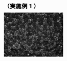
- Example 1 Using a cold parison method, 0.33% carbon dioxide gas is kneaded and injected into a PET resin containing a tea-based colorant, and then molded while holding pressure so that the preform does not foam, After giving in-mold cooling, the preform was taken out and sufficiently cooled to room temperature. Thereafter, the outer surface of the preform body was heated to 111 ° C. and blow-molded. When the obtained bottle was visually confirmed, it had a pear-like appearance. The standard deviation of the lightness was calculated by image processing of the bottle photograph, and it was 38 when evaluated by the maximum value of the six torso parts. The surface roughness of the bottle body was 1.3 ⁇ m, and it was confirmed that the surface was smooth. Furthermore, when the number of cells in the thickness direction was measured from a cross-sectional photograph of the bottle body, it was 33.3 on average. A cross-sectional photograph of the bottle body is shown in FIG.
- Example 2 The bottle was molded by the same production method as in Example 1 except that the preform body outer surface temperature at the time of blow molding was 96 ° C. When the obtained bottle was visually confirmed, it had a pear-like appearance.
- the standard deviation of the brightness calculated from the photograph of the bottle body was 29, the surface roughness Ra of the bottle body was 0.12 ⁇ m, and the average number of cells in the thickness direction was 28.
- Example 3 The bottle was molded by the same production method as in Example 1 except that a non-colored PET resin not containing a colorant was used and the preform body outer surface temperature during blow molding was 106 ° C. When the obtained bottle was visually confirmed, it looked like a polka dot with a pear-like appearance.
- the standard deviation of the brightness calculated from the photograph of the bottle body was 63, the surface roughness Ra of the bottle body was 0.9 ⁇ m, and the average number of cells in the thickness direction was 2.7.
- Example 4 Using a hot parison method, 0.105% nitrogen gas was kneaded into a PET resin containing no colorant, and the resin was injection filled. Thereafter, a holding time and a cooling time were given so that the preform outer surface temperature was 83 ° C. and the inner surface temperature was 89 ° C. immediately after the injection mold was opened. After the injection mold was opened, it was blow molded as it was after an annealing time of 25 seconds. When the obtained bottle was visually confirmed, it had a pear-like appearance. The standard deviation of the brightness calculated from the photograph of the bottle body was 50, the surface roughness Ra of the bottle body was 0.08 ⁇ m, and the average number of cells in the thickness direction was 3.0.
- Example 5 The bottle was molded by the same production method as in Example 4 except that 0.12% nitrogen gas was kneaded and injection filled. When the obtained bottle was visually confirmed, it looked like a sleet while exhibiting a pear-like appearance.
- the standard deviation of the brightness calculated from the photograph of the bottle body was 36, the surface roughness Ra of the bottle body was 0.1 ⁇ m, and the average number of cells in the thickness direction was 14.0.
- a cross-sectional photograph of the bottle body is shown in FIG.
- Example 6 Same as Example 4 except that 0.09% nitrogen gas was kneaded and injection filled, and the holding time and cooling time were adjusted so that the preform outer surface temperature was 91 ° C. and the inner surface 107 ° C. immediately after the injection mold was opened.
- the bottle was molded by the manufacturing method. When the obtained bottle was visually confirmed, bubbles and irregularities inside the container and on the inner surface side were visually recognized while exhibiting a satin-like appearance, and looked like a ground glass.
- the standard deviation of the brightness calculated from the photograph of the bottle body is 53, the surface roughness Ra of the bottle body is 0.04 ⁇ m (the inner surface roughness Ra is 3.1 ⁇ m), and the average number of cells in the thickness direction is 3.8. there were.
- Example 7 A PET resin containing a tea-based colorant was kneaded with 0.33% carbon dioxide gas and injection-filled, and the pressure holding time was adjusted so that the preform outer surface temperature was 100 ° C. and the inner surface was 115 ° C. immediately after the injection mold was opened.
- the bottle was molded by the same production method as in Example 4 except that the cooling time was adjusted. When the obtained bottle was visually confirmed, a large air bubble inside the container was visible while showing a pear-like appearance, and it looked like a lacquer ware.
- the standard deviation of the brightness calculated from the photograph of the bottle body was 43, the surface roughness Ra of the bottle body was 0.9 ⁇ m, and the average number of cells in the thickness direction was 4.0.
- Example 8> The bottle was molded by the same production method as in Example 4 except that the pressure holding time and the cooling time were adjusted so that the preform outer surface temperature was 108 ° C. and the inner surface was 124 ° C. immediately after the injection mold was opened. When the obtained bottle was visually confirmed, a large air bubble inside the container was visible while showing a pear-like appearance, and it looked like a lacquer ware.
- the standard deviation of the brightness calculated from the photograph of the bottle body was 54, the surface roughness Ra of the bottle body was 4.3 ⁇ m, and the average number of cells in the thickness direction was 4.0.
- Example 9 A PET resin containing a yellow colorant was mixed with 0.08% nitrogen gas and injection-filled, and the pressure holding time and cooling so that the preform outer surface temperature was 93 ° C. and the inner surface was 108 ° C. immediately after the injection mold was opened.
- a bottle was molded by the same production method as in Example 4 except that the time was adjusted. When the obtained bottle was visually confirmed, bubbles and irregularities inside the container and on the inner surface side were visually recognized while exhibiting a satin-like appearance, and looked like a colored ground glass.
- the standard deviation of the brightness calculated from the photograph of the bottle body is 22, the surface roughness Ra of the bottle body is 0.04 ⁇ m (the inner surface roughness Ra is 4.6 ⁇ m), and the average number of cells in the thickness direction is 4.6. there were.
- Example 10 Same as Example 4 except that 0.08% nitrogen gas was kneaded and injection filled, and the holding time and cooling time were adjusted so that the preform outer surface temperature was 86 ° C. and the inner surface 101 ° C. immediately after the injection mold was opened.
- the bottle was molded by the manufacturing method. When the obtained bottle was visually confirmed, air bubbles inside the container could be visually recognized while exhibiting a satin-like appearance, and looked like a scale.
- the standard deviation of the brightness calculated from the photograph of the bottle body is 52, the surface roughness Ra of the bottle body is 0.1 ⁇ m (the inner surface roughness Ra is 7.6 ⁇ m), and the average number of cells in the thickness direction is 3.7. there were.
- Example 11 In Example 10, the pressure holding time was lengthened, but the cooling time was shortened accordingly, and the preform outer surface temperature immediately after opening the injection mold was adjusted to 87 ° C. and the inner surface was 102 ° C. to form a bottle. When the obtained bottle was visually confirmed, small bubbles on the inner and outer surfaces of the container and large bubbles inside the container could be visually recognized while showing a satin appearance, and it seemed that there was a lame in the ground glass.
- the standard deviation of the brightness calculated from the photograph of the bottle body was 53, the surface roughness Ra of the bottle body was 0.05 ⁇ m, and the average number of cells in the thickness direction was 3.6.
- Example 1 A preform was injection molded under the same conditions as in Example 1 except that the cold parison method was used, PET resin not containing a colorant was used, and nitrogen gas was kneaded at 0.105%. Thereafter, the outer surface of the preform body was heated to 103 ° C. and blow-molded. When the obtained bottle was visually confirmed, it exhibited a white pearl tone as a whole. The standard deviation of the brightness calculated from the photograph of the bottle body was 38, but since it did not contain a colorant, the appearance of the bottle was visually poor. The surface roughness Ra of the bottle body was 0.12 ⁇ m, and the average number of cells in the thickness direction was 17.
- Example 4 except that 0.12% nitrogen gas was kneaded and injection filled, and the holding time and cooling time were adjusted so that the preform outer surface temperature immediately after opening the injection mold was 95 ° C. and the inner surface temperature was 111 ° C. Bottles were molded using the same manufacturing method. When the obtained bottle was visually confirmed, the presence of light and darkness was not visible, and the whole had a milky white pearl tone. The standard deviation of the brightness calculated from the photograph of the bottle body was 16, the surface roughness Ra of the bottle body was 0.06 ⁇ m, and the average number of cells in the thickness direction was 27.8. A cross-sectional photograph of the bottle body is shown in FIG.
- ⁇ Comparative example 4> Using a hot parison method, using a resin that does not contain a colorant and foaming gas, adjusting the holding time and cooling time so that the preform outer surface temperature is 100 ° C. and the inner surface temperature is 115 ° C. immediately after the injection mold is opened.
- the bottle was molded by the same production method as in Example 4 except for the above. Since the obtained bottle was a non-colored, non-foamed transparent bottle, the presence of light and darkness could not be visually recognized.
- the standard deviation of the brightness calculated from the photograph of the bottle body was 2, and the surface roughness Ra of the bottle body was 0.04 ⁇ m (the average number of cells in the thickness direction was 0 because it was not foamed).
- Table 1 shows the results of comparative studies in this example. Moreover, the external appearance photograph of the container obtained in Example 7 and 10 is shown in FIG. Furthermore, images of Examples 1 and 5 and Comparative Example 2 are shown in FIGS. 9, 10, and 11 as examples of grayscale processed images of digital microscope photographs used for bottle evaluation.
- trunk wall 3 resin matrix 5: flat foam cell 5a: top foam cell 7: skin layer 11: trunk D: dark part L: bright part
Landscapes
- Engineering & Computer Science (AREA)
- Chemical & Material Sciences (AREA)
- Mechanical Engineering (AREA)
- Ceramic Engineering (AREA)
- Health & Medical Sciences (AREA)
- Materials Engineering (AREA)
- Manufacturing & Machinery (AREA)
- Chemical Kinetics & Catalysis (AREA)
- Medicinal Chemistry (AREA)
- Polymers & Plastics (AREA)
- Organic Chemistry (AREA)
- Containers Having Bodies Formed In One Piece (AREA)
- Blow-Moulding Or Thermoforming Of Plastics Or The Like (AREA)
- Molding Of Porous Articles (AREA)
Abstract
熱可塑性樹脂からなり且つ非ラミネート構造の器壁を有していると共に、該器壁内部に発泡セルが分布している発泡領域が少なくとも胴部の一部に存在している発泡プラスチック容器において、前記胴部の表面は、表面粗さRaが5μm以下の平滑面となっていると共に、前記発泡領域での胴部の外面は、光線反射率が低い暗部(D)が該光線反射率の高い明部(L)の間に多数分布しており、これにより、梨地様模様を呈していることを特徴とする。
Description
本発明は、梨地様外観を有する発泡プラスチック容器に関するものであり、より詳細には、熱可塑性樹脂からなり且つ非ラミネート構造の器壁を有していると共に、該器壁内部に発泡セルが分布している発泡領域が少なくとも胴部の一部に存在している発泡プラスチック容器に関するものである。
現在、ポリエチレンテレフタレート(PET)に代表されるポリエステル容器は、透明性、耐熱性、ガス遮断性等の特性に優れており、種々の用途に広く使用されている。
一方、近年では、資源の再利用が強く求められ、上記のようなポリエステル容器に関しても、使用済みの容器を回収し、リサイクル樹脂として種々の用途への再利用が図られている。
一方、近年では、資源の再利用が強く求められ、上記のようなポリエステル容器に関しても、使用済みの容器を回収し、リサイクル樹脂として種々の用途への再利用が図られている。
ところで、包装容器内に収容される内容物については、光により変質しやすいもの、例えばある種の飲料、医薬品、化粧品などは、顔料等の着色剤を樹脂に配合した樹脂組成物を用いて成形された不透明容器に収容されて提供される。このような不透明容器では、資源の再利用の点からは、着色剤の配合は望ましくない。従って、着色剤を配合せずに遮光性(不透明性)を付与するという観点から、マイクロセルラー技術を利用して容器壁が発泡している発泡容器が種々提案されている。
このような発泡容器では、容器壁中での発泡セルの分布状態により、着色剤を配合することなく遮光性が付与されると同時に、光沢性の高い外観(例えばパール調)が得られることが知られているが(特許文献1参照)、さらに、容器壁を形成する樹脂に着色剤が分散されている場合には、極めて特異的な外観が得られ、例えば、金属顔料が使用されていないにもかかわらず、金属光沢が発現することが知られている(特許文献2参照)。
即ち、発泡セルが分布している発泡容器は、着色剤が分散された樹脂を用いて成形されている場合には、独特の外観が得られ、高い加飾性が付与されるため、リサイクル性を有していなくとも、高い商品価値を有する。
本発明者等は、マイクロセルラー技術を利用して発泡構造が形成されている発泡プラスチック容器について検討していく過程で、発泡セルの分布形態や大きさを適宜の範囲に調整することにより、着色剤の配合及び無配合にかかわらず、独特の梨地様模様の外観が発現することを見出した。
従って、本発明の目的は、熱可塑性樹脂からなり且つ非ラミネート構造の器壁を有していると共に、該器壁内部に発泡セルが分布している発泡領域が少なくとも胴部の一部に存在している発泡プラスチック容器において、梨地様外観を有する発泡プラスチック容器を提供することにある。
本発明によれば、熱可塑性樹脂からなり且つ非ラミネート構造の器壁を有していると共に、該器壁内部に発泡セルが分布している発泡領域が少なくとも胴部の一部に存在している発泡プラスチック容器において、
前記胴部の外面は、表面粗さRaが5μm以下の平滑面となっていると共に、
前記発泡領域での胴部外面は、光線反射率が低い暗部が該光線反射率の高い明部の間に多数分布しており、これにより、梨地様模様を呈していることを特徴とする発泡プラスチック容器が提供される。
前記胴部の外面は、表面粗さRaが5μm以下の平滑面となっていると共に、
前記発泡領域での胴部外面は、光線反射率が低い暗部が該光線反射率の高い明部の間に多数分布しており、これにより、梨地様模様を呈していることを特徴とする発泡プラスチック容器が提供される。
本発明の発泡プラスチック容器においては、
(1)前記発泡領域での胴部外面を倍率50倍で写真撮影し、256階調でグレースケール処理して明度分布を算出した時、明度標準偏差の最大値が18以上であること、
が梨地様模様の視認性の点で好適である。
また、本発明においては、
(2)前記発泡領域の暗部を通して容器内部が視認されること、
が意匠性の点で好適である。この場合、前記発泡領域での胴部の内面は、表面粗さRaが0.1~100μmの範囲にあることが好ましい。
さらに、本発明の発泡プラスチック容器は、前記器壁は、着色剤が配合された熱可塑性樹脂或いは着色剤無配合の熱可塑性樹脂(即ち、無着色樹脂)により形成されているという態様を採り得るが、着色剤無配合の熱可塑性樹脂により器壁が形成されている場合には、前記発泡領域では、胴部厚み方向断面で見て、発泡セルの個数が平均して14個以下であることが好ましい。
本発明の発泡プラスチック容器は、自己加飾性を有しており、模様が印刷されたフィルムや着色剤が配合された未発泡の樹脂層がラミネートされていないにもかかわらず、それ単独で、表面が平滑でありながら梨地様模様という独特の外観を有しており、フィルムの貼り付け等によるラミネート構造を有しているものに比して、安価で加飾されており、その商品価値が極めて高い。
また、梨地様模様は、着色剤が配合されていない熱可塑性樹脂を用いて成形された容器にも発現しており、特に、着色剤が配合されていない場合には、リサイクル性にも優れている。
また、梨地様模様は、着色剤が配合されていない熱可塑性樹脂を用いて成形された容器にも発現しており、特に、着色剤が配合されていない場合には、リサイクル性にも優れている。
かかる本発明の発泡プラスチック容器は、発泡による軽量性ばかりか、梨地様模様という独特の外観を有していることから、特に加飾が要求される分野、特に化粧品容器などの用途に極めて有用である。
<発泡プラスチック容器及び原理>
本発明の発泡プラスチック容器は、熱可塑性樹脂を用いて成形されたものであり且つ非ラミネート構造を有しており、容器壁の胴部の少なくとも一部(通常は胴部全体)には、発泡セルが分布している発泡領域が形成されており、該発泡領域が形成されている部分を含めて、胴部の外面は、表面粗さRa(JIS Z-0601-1994、算術平均粗さ)が5μm以下の平滑面となっているという基本構造を有している。
かかる基本構造は、特許文献1に開示されている発泡容器でも有しており、例えば、その概略断面構造は、図1に示されている。
本発明の発泡プラスチック容器は、熱可塑性樹脂を用いて成形されたものであり且つ非ラミネート構造を有しており、容器壁の胴部の少なくとも一部(通常は胴部全体)には、発泡セルが分布している発泡領域が形成されており、該発泡領域が形成されている部分を含めて、胴部の外面は、表面粗さRa(JIS Z-0601-1994、算術平均粗さ)が5μm以下の平滑面となっているという基本構造を有している。
かかる基本構造は、特許文献1に開示されている発泡容器でも有しており、例えば、その概略断面構造は、図1に示されている。
即ち、図1において、この容器の胴部壁1を形成している樹脂マトリックス3中に発泡セル5が多数分布して発泡領域を形成しているが、その外表面には、発泡セル5が分布していない薄い表皮層7が形成されており、かかる表皮層7の存在により、その外面は、平滑面となっており、その表面粗さRaは、5μm以下である。表皮層7が存在していないと、発泡セル5により、外面に凹凸が形成されてしまい、外面が平滑面とならなくなってしまう。
また胴部壁1の外面が、表面粗さRaが5μmよりも大きな粗面となっていると、後述する発泡のコントロールにより梨地様模様を発現させたとしても高級感が低下してしまう。即ち、梨地様模様の加飾性を最大限に発揮させるためには、発泡領域を含め、胴部壁1の外面は、上記のような平滑面となっていることが必要である。
また胴部壁1の外面が、表面粗さRaが5μmよりも大きな粗面となっていると、後述する発泡のコントロールにより梨地様模様を発現させたとしても高級感が低下してしまう。即ち、梨地様模様の加飾性を最大限に発揮させるためには、発泡領域を含め、胴部壁1の外面は、上記のような平滑面となっていることが必要である。
また、上記の発泡セル5は、マイクロセルラー技術を利用しての発泡によって形成されているものである。マイクロセルラーによる発泡とは、不活性ガスを発泡剤として樹脂に含浸させ、このガスを気泡に成長させて発泡セルを物理的に形成するという技術であり、小さな発泡セルを全体に均等に分布するように発泡をコントロールし得る点で、熱分解により窒素や炭酸ガス等のガスを発生する化合物を発泡剤として用いた化学発泡とは異なっている。
また、上記の容器胴部壁1は延伸されており、このため、発泡セル5は、延伸方向に引き伸ばされた偏平形状を有している。
本発明の発泡プラスチック容器は、上記のような基本構造と共に、胴部の外面から観察したとき、光線反射率が高い明部の間に、光線反射率が低い暗部が多数分布するように発泡がコントロールされており、これにより、梨地様模様を呈しているという点に大きな特徴を有している。
この梨地様模様の発現の原理を示す図2を参照して、発泡セル5が樹脂マトリックス3中に分布している場合、発泡セル5が存在している部分では、外面からの光が発泡セル5で反射するが、発泡セル5が存在していない部分では、光は樹脂マトリックス3中に侵入して透過していく。このため、発泡セル5が多く分布している部分(密に分布している部分)は、光の反射量が多いため(光の透過量が少ない)、明るい明部Lとなり、発泡セル5の分布が少ない部分(発泡セル5の分布が疎な部分)では、光の反射量が少ないため(光の透過量が多い)、相対的に暗い暗部Dとなる。
本発明においては、このような発泡セル5の分布による明暗差によって、梨地様の模様を呈するのである。
また、梨地様模様は、細かな凹凸によって形成されるものであり、表面がざらざらとしたものであるが、本発明における梨地様模様は、表面の凹凸ではなく、光の反射の相違による明暗によって形成されるものであり、一般的な梨地模様とは異なっている。しかも、本発明において、発泡セル5が分布している発泡領域には、その外面に薄い表皮層7が形成されているため、全体として光沢感があり、従って、艶のないマット調の外観とも異なっている。
本発明においては、このような発泡セル5の分布による明暗差によって、梨地様の模様を呈するのである。
また、梨地様模様は、細かな凹凸によって形成されるものであり、表面がざらざらとしたものであるが、本発明における梨地様模様は、表面の凹凸ではなく、光の反射の相違による明暗によって形成されるものであり、一般的な梨地模様とは異なっている。しかも、本発明において、発泡セル5が分布している発泡領域には、その外面に薄い表皮層7が形成されているため、全体として光沢感があり、従って、艶のないマット調の外観とも異なっている。
本発明において、かかる明暗差により梨地様模様が発現されていることは、発泡セル5が分布している胴部壁1の外面について測定された明度分布により示される。即ち、胴部壁1の外面を、倍率50倍で写真撮影し、256階調でグレースケール処理して明度分布を算出した時、明度標準偏差の最大値が18以上、特に20以上となる。この最大値が大きいほど、明暗のある部分が多く存在していることを示す。即ち、明度標準偏差の最大値が上記範囲よりも小さい場合には、明暗差のある部分が少なく、このため、梨地様模様は不鮮明となり、均質な外観を示すようになる。
このように、本発明の発泡プラスチック容器が呈する梨地様模様は、発泡セル5の分布による明暗差によりもたらされる。
上述した原理にしたがって明暗差を生じ、梨地様模様を発現させるパターンは、大きく分けて2通りある。
一つは、径Lの大きな発泡セル5が表層部に分布しているパターンであり、このパターンは、図3に示されている。
また、他の一つは、気泡が密に分布している部分と疎に分布している部分を有しているパターンであり、このパターンは、図4に示されている。
一つは、径Lの大きな発泡セル5が表層部に分布しているパターンであり、このパターンは、図3に示されている。
また、他の一つは、気泡が密に分布している部分と疎に分布している部分を有しているパターンであり、このパターンは、図4に示されている。
図3のパターンでは、外面に最も近い最上部に位置する発泡セル5aの気泡径が大きい特徴がある。最外層の気泡径が大きい場合、発泡層5aと発泡層5bにおいて、外面までのマトリックス3の厚みに大きな差が生じる。最上部の発泡セル5aが存在する部分が明部Lとなり(即ち、光は発泡セル5aで反射)、最上部の発泡セル5aの間隙部分が暗部Dとなる(即ち、光は発泡セル5bで反射)。特に、樹脂マトリックス3に着色剤が含まれている場合、光がこの間隙部分を通り、発泡セル5bで光反射するまでの、着色剤による光の吸収量が、発泡セル5aで光反射するまでの光の吸収量に比して極めて大きい。
そのため、暗部Dと明部Lで明暗差がはっきりし、これにより、梨地様模様を呈している。
このような図3のパターンにおいて、表層部に分布している発泡セル5aの、最大延伸方向での気泡径を、平均して90μm以上、特に40~150μmの範囲に設定することが好適である。
そのため、暗部Dと明部Lで明暗差がはっきりし、これにより、梨地様模様を呈している。
このような図3のパターンにおいて、表層部に分布している発泡セル5aの、最大延伸方向での気泡径を、平均して90μm以上、特に40~150μmの範囲に設定することが好適である。
また、図4のパターンは、基本的に胴部壁1に分布している発泡セル5が密に分布している部分と疎に分布している部分を有しており、密に分布している部分が、反射の多い明部Lとなり、疎に分布している部分が、反射の少ない暗部Dとなる。
かかるパターンは、特に発泡セル5の分布のみによって明暗差を生じせしめるというものであり、特に着色剤が配合されておらず、発泡セル5による散乱、多重反射により乳白色の外観を有する発泡容器では、このパターンで梨地様模様が発現される。
気泡径は求める外観に対して適宜の範囲に設定すればよく、例えば最上部、中央部、最下部いずれかの発泡層での発泡セル5の気泡径が平均して50μm以下、より好ましくは30μm以下、さらに好ましくは20μm以下と微細にするときめの細やかな明暗となり、最上部、中央部、最下部いずれかの発泡層での発泡セル5の平均気泡径を上記よりも大きく、例えば平均して50~250μm、特に150μm以下の範囲とすることできめの粗い明暗となる(例えば図8参照)。
上述した図3及び図4の何れのパターンにおいても、発泡領域での胴部厚み方向断面で見て、発泡セル5の個数も梨地様模様(明暗差)に影響を与える。例えば、この個数が多すぎると、表層部のみならず、胴部壁の内部に存在する発泡セル5での反射が大きくなり、明暗差が小さくなって、梨地様模様が不鮮明となる傾向がある。
従って、前述した着色剤が配合されていない無着色の乳白色発泡容器では、発泡セル5の分布のみによって明暗差が発現するため、この発泡セル5の個数が明暗差に与える影響が着色発泡容器に比してより大きいため、この個数は、好ましくは平均して14個以下、より好ましくは10個以下、さらに好ましくは6個以下とすることが、梨地様模様をより明確に視認できるという観点から好適である。
一方、着色剤が配合されている容器においては、マトリックスにより光が十分に吸収されれば、最外層より深い部分の発泡セルの個数はさほど梨地様模様に影響は与えず、表層部のセル径が大きい、もしくはセル疎密があれば梨地様外観が発現されるが、容器内部の視認性の面では上述する発泡セル5の個数が好適である。
上記のような図3或いは図4のパターンで梨地様模様が発現している本発明の発泡容器の外観写真は、図5に示されている。この図5に示されているボトル形状の発泡容器は、着色剤が配合されているものであるが、発泡領域の全体にわたって、梨地様模様を呈していることが判る。
例えば上述した図3或いは4のパターンで梨地様模様が発現している本発明の発泡容器において、発泡により容器内面側に凹凸を付与することで、容器内部を視認させつつ、容器内面側の凹凸による光の乱反射により、表面は平滑でありながら、容器外観に梨地様模様に加え、奥行きのある凹凸感を付与した発泡容器を得ることもできる。このような場合、発泡セル5の個数が多いと容器内面側の凹凸の視認性が低下するため、この個数は、上述した通り、好ましくは平均して14個以下、より好ましくは10個以下、さらに好ましくは6個以下とすることが望ましい。容器内面凹凸の大きさに関しては、求める外観に応じて設定されるため特に制限はないが、例えば平均表面粗さRaで0.1乃至は100μm、好ましくは1乃至は10μmの範囲で設定される。
<容器材料>
本発明の発泡プラスチック容器を形成する熱可塑性樹脂、即ち、図1におけるマトリックス3の樹脂としては、後述する不活性ガスを含浸させてのマイクロセルラーによる発泡が可能である限り特に制限されず、それ自体公知の熱可塑性樹脂を使用することができる。例えば、低密度ポリエチレン、高密度ポリエチレン、ポリプロピレン、ポリ1-ブテン、ポリ4-メチル-1-ペンテンあるいはエチレン、プロピレン、1-ブテン、4-メチル-1-ペンテン等のα-オレフィン同志のランダムあるいはブロック共重合体、環状オレフィン共重合体などのオレフィン系樹脂;エチレン・酢酸ビニル共重合体、エチレン・ビニルアルコール共重合体、エチレン・塩化ビニル共重合体等のエチレン・ビニル系共重合体;ポリスチレン、アクリロニトリル・スチレン共重合体、ABS、α-メチルスチレン・スチレン共重合体等のスチレン系樹脂;ポリ塩化ビニル、ポリ塩化ビニリデン、塩化ビニル・塩化ビニリデン共重合体、ポリアクリル酸メチル、ポリメタクリル酸メチル等のビニル系樹脂;ナイロン6、ナイロン6-6、ナイロン6-10、ナイロン11、ナイロン12等のポリアミド樹脂;ポリエチレンテレフタレート(PET)、ポリブチレンテレフタレート、ポリエチレンナフタレート、及びこれらの共重合ポリエステル等のポリエステル樹脂;ポリカーボネート樹脂;ポリフエニレンオキサイド樹脂;ポリ乳酸など生分解性樹脂;などを使用することができる。勿論、これらの熱可塑性樹脂のブレンド物を使用することもできる。
本発明において、最も好適な樹脂は、発泡セル5の形態や延伸成形性の観点から、PETに代表されるポリエステル樹脂である。
また、着色のために上記樹脂に配合される着色剤としては、特に制限されず、目的とする色に応じて、種々の顔料を使用することができる。
尚、所謂メタリック顔料と呼ばれる高価な顔料、例えば、銅粉、アルミニウム粉、亜鉛粉、金粉、銀粉などの金属粉顔料や、雲母や鱗片状チタン、鱗片状ステンレスなどの鱗片状(フレーク状)顔料、或いはこのような鱗片状顔料の表面をコバルト、ニッケル、チタン等の金属微粒子で被覆した顔料(光輝顔料)を使用し、これらを、適宜、他の色の顔料等と併用することにより、メタリックな外観を得ることができるが、本発明では、このようなメタリック顔料を使用せずとも、特許文献2と同様、金属光沢を有する加飾性の高い外観を得ることができるため、コストの低減からも、このような高価な顔料を敢えて使用する必要はない。即ち、発泡セル5が分布している発泡領域では、光の散乱、反射、干渉及び表皮層7によるマニキュア効果による光沢或いは艶が加わって当該色に応じた金属色を示すようにできる。例えば、金色を得ようとする場合には、橙~緑系の非金属顔料を使用すると、金色を呈することができる。
尚、所謂メタリック顔料と呼ばれる高価な顔料、例えば、銅粉、アルミニウム粉、亜鉛粉、金粉、銀粉などの金属粉顔料や、雲母や鱗片状チタン、鱗片状ステンレスなどの鱗片状(フレーク状)顔料、或いはこのような鱗片状顔料の表面をコバルト、ニッケル、チタン等の金属微粒子で被覆した顔料(光輝顔料)を使用し、これらを、適宜、他の色の顔料等と併用することにより、メタリックな外観を得ることができるが、本発明では、このようなメタリック顔料を使用せずとも、特許文献2と同様、金属光沢を有する加飾性の高い外観を得ることができるため、コストの低減からも、このような高価な顔料を敢えて使用する必要はない。即ち、発泡セル5が分布している発泡領域では、光の散乱、反射、干渉及び表皮層7によるマニキュア効果による光沢或いは艶が加わって当該色に応じた金属色を示すようにできる。例えば、金色を得ようとする場合には、橙~緑系の非金属顔料を使用すると、金色を呈することができる。
着色剤が配合されている発泡容器では、着色剤量が多い程、明暗差がはっきりし、梨地様模様が明瞭となる傾向がある。即ち、着色剤の濃度が高い程、前述した発泡セル5間での光の吸収量が多いため、発泡セル5による光の吸収量の低下を視認し易くなるためである。このような観点から、上述した着色剤は、一般に、前述した樹脂100質量部当り、0.1乃至20質量部、特に2乃至10質量部の量で使用されることが望ましい。
<容器外観>
上述した説明から理解されるように、本発明の発泡容器は、着色剤が配合された熱可塑性樹脂を用いて成形された着色発泡容器と、着色剤が配合されず、無着色の熱可塑性樹脂を用いて成形された無着色発泡容器とがある。
上述した説明から理解されるように、本発明の発泡容器は、着色剤が配合された熱可塑性樹脂を用いて成形された着色発泡容器と、着色剤が配合されず、無着色の熱可塑性樹脂を用いて成形された無着色発泡容器とがある。
着色発泡容器は、樹脂マトリックス3が着色剤を含んでいるため、全体として着色剤の色が反映された色を呈しており、このような色の中で、明暗差による梨地様模様が発現している。ただ、発泡セル5が分布している発泡領域では、この色は、発泡セル5による光の散乱や反射の影響により、着色剤が呈する本来の色とは若干変わった色味となり、例えば茶色の着色剤では、金色に近い色となる。例えば、図5に示されているボトル形態の発泡容器は、着色発泡容器の外観写真であるが、この首部は螺子が存在しているため、強度が要求されることから発泡セルは分布しておらず、従って、着色剤本来の色を呈しており、発泡領域となっている胴部では、この色とは異なった色を呈していることが理解されよう。
また、着色発泡容器では、先にも述べたように、胴部壁1の厚み方向での発泡セル5の個数の影響は少なく、外面に近い表層部分での発泡セル5の大きさや分布を調整することによって、梨地様模様を発現することができる。
さらに、着色発泡容器では、表皮層7の厚み(外面に近い最上部に位置する発泡セル5と外表面との間隔に相当)は、大まかに言って、平均して500μm以下の範囲(一般にボトルの胴部厚みの半分以下)に設定されていることが好ましい。表皮層7の厚みが厚いと、発泡領域の全てにおいて、着色剤による光の吸収が大きいため、明部Lと暗部Dとの光線反射率の差が小さくなり、明暗差の視認が困難となり、梨地様模様の鮮明さが損なわれるおそれがあるからである。
これに対して、着色剤を含んでいない熱可塑性樹脂により成形された無着色発泡容器は、発泡による光の散乱や反射により、発泡領域では、全体として乳白色を呈し、このような乳白色の中に、明暗差による梨地様模様が発現している。
かかる無着色発泡容器では、例えば、図5の着色発泡容器と同様、ボトル形態の無着色発泡容器では、首部の部分には発泡セルが分布していないため透明であり、さらに発泡セルが分布している発泡領域(胴部)では、光が透過する発泡セル5の間隙(暗部)を通して内部を視認することができ、発泡セル5が胴部壁1中に漂ったような乳白色の明部Lとして視認され、梨地様模様の外観を呈しながら、みぞれのような状態に見える。
かかる無着色発泡容器では、例えば、図5の着色発泡容器と同様、ボトル形態の無着色発泡容器では、首部の部分には発泡セルが分布していないため透明であり、さらに発泡セルが分布している発泡領域(胴部)では、光が透過する発泡セル5の間隙(暗部)を通して内部を視認することができ、発泡セル5が胴部壁1中に漂ったような乳白色の明部Lとして視認され、梨地様模様の外観を呈しながら、みぞれのような状態に見える。
このような無着色発泡容器では、着色剤を含んでいないため、発泡セル5の分布(疎密)によってのみ梨地様模様が発現するものであり、例えば、先にも述べたように、多くの場合、図4に示すパターンで梨地様模様が発現し、胴部壁1の厚み方向での発泡セルの分布数が梨地様模様の生成に大きな影響を与えることとなる。例えば、発泡セル5が明暗差が視認できないように密に形成されていると、特許文献1で示されているパール調外観を呈するものとなってしまう。
さらに、この無着色発泡容器では、発泡セル5が分布していない表層部7の厚みは、特に制限されず、最も上部に位置している発泡セル5aの形態が表面に反映されない程度の厚みを有していればよい。
<発泡プラスチック容器の製造>
本発明の発泡プラスチック容器は、発泡剤として、不活性ガス、例えば炭酸ガス、窒素ガスが使用され、マイクロセルラー技術を利用しての物理発泡を利用して、それ自体公知の方法を採用して発泡プリフォームを作成し、この発泡プリフォームを延伸成形することにより製造されるが、梨地様模様発現のために、発泡をコントロールすることが必要である。即ち、梨地様模様を発現するために、不活性ガスから発生する発泡セル5の大きさ、個数、分布状態を調整することが必要となる。
尚、原理的には、特に延伸成形を行わずとも本発明の発泡プラスチック容器を製造することは可能であるが、延伸成形が行われていないものは、発泡セル5が偏平しておらず、球形或いは球形に近い形状を有しているため、暗部Dとなる発泡セル5の間隙や発泡セル5の分布が疎な部分の面積割合等のコントロールが非常に困難であるため、現実的には、延伸成形により、図1に示されているように、偏平状に引き伸ばされた形状の発泡セル5を形成するという手段が採用される。
例えば、発泡セル5の大きさや個数、密度は、発泡剤として使用される不活性ガスの溶解量、発泡に際しての加熱条件に大きく依存し、不活性ガスの溶解量が多い程、発泡セル5の個数を多くすることができ、また、発泡のための加熱温度が高く、加熱時間が長い程、発泡セル5を大きくすることができる。また、不活性ガスの種類によってプリフォームの形成に使用する熱可塑性樹脂に対する溶解度が異なり、また、加熱に伴い生成する発泡セルの成長速度も異なる。例えば、炭酸ガスは、窒素ガスに比して、熱可塑性樹脂に対する溶解度が多いが、発泡セルが大きく成長しやすく、セル数が少なく且つ大きなセルを形成し易い。
従って、上記のような性質を利用して、明確な梨地様模様が発現するように、各種条件を設定することとなる。
従って、上記のような性質を利用して、明確な梨地様模様が発現するように、各種条件を設定することとなる。
ところで、本発明の発泡プラスチック容器を製造する方法は、延伸成形に供する発泡プリフォームを、2ステージで作成するコールドパリソン法と1ステージで作成するホットパリソン法とに分けられる。
図6には、上記の方法によって作成されるボトル用の発泡プリフォーム50が示されている。
この発泡プリフォーム50は、全体として試験管形状を有しており、延伸成形により得られるボトルのノズル部に対応する首部51と、首部51に連なる筒状の成形部53を備えている。
首部51は、延伸成形されない部分であり、螺子51a及びサポートリング51bを外面に有しており、成形部53は、延伸成形される部分であり、その下端は、底壁55によって閉じられている。また、図から理解されるように、成形部53の器壁内部には、発泡セル5’が分布しているが、首部51は、発泡セル5’は分布しておらず、非発泡領域となっている。即ち、首部51内に発泡セル5’が分布していると、螺子51aやサポートリング51bの強度低下を生じ、これらの機能が損なわれてしまうからである。
尚、上記成形部53の厚みは、後述する延伸工程での薄肉化を考慮して、目的とする容器の胴部壁の厚みが得られるようなものとする。
以下、上記の発泡プリフォームを例にとって、コールドパリソン法及びホットパリソン法について説明する。
1.コールドパリソン法(2ステージ法);
この方法は、不活性ガスが含浸されている未発泡のプリフォームを成形し、次いで、これを加熱しての発泡により発泡セル5’を生成せしめて発泡プリフォーム50を得、この後に、延伸成形を行うという方法であり、発泡セル5’を生成せしめる発泡工程が独立の工程として設けられるというものであり(即ち、外部加熱により発泡を行う)、図1で示されている表皮層7のコントロールが容易であるという利点がある。
この方法は、不活性ガスが含浸されている未発泡のプリフォームを成形し、次いで、これを加熱しての発泡により発泡セル5’を生成せしめて発泡プリフォーム50を得、この後に、延伸成形を行うという方法であり、発泡セル5’を生成せしめる発泡工程が独立の工程として設けられるというものであり(即ち、外部加熱により発泡を行う)、図1で示されている表皮層7のコントロールが容易であるという利点がある。
また、プリフォームは、先にも述べられているように、着色発泡容器を製造する場合には、所定の熱可塑性樹脂に所定の色を有する着色剤が配合されたものを成形用樹脂として使用し、無着色の発泡容器を製造する場合には、着色剤が配合されていない熱可塑性樹脂を成形用樹脂として使用することにより得られる。
不活性ガスが含浸されているが未発泡のプリフォームは、予め成形された不活性ガスが含浸していないプリフォームを、加熱もしくは非加熱下で高圧の不活性ガス雰囲気下に置くことにより行うことができる。
既に述べたように、不活性ガスの種類によってガスの溶解度は異なるが、この温度が高いほど、ガスの溶解量は少ないが含浸速度は速く、温度が低いほどガスの溶解量は多いが、含浸には時間がかかることとなる。また、ガスの溶解量が多いほど、発泡セル5’を微細とし且つ高密度で分布させることができる。従って、発泡セル5’を大きくし、さらにその個数を少なくする上では、ガスの溶解量をある程度制限するのがよい。
既に述べたように、不活性ガスの種類によってガスの溶解度は異なるが、この温度が高いほど、ガスの溶解量は少ないが含浸速度は速く、温度が低いほどガスの溶解量は多いが、含浸には時間がかかることとなる。また、ガスの溶解量が多いほど、発泡セル5’を微細とし且つ高密度で分布させることができる。従って、発泡セル5’を大きくし、さらにその個数を少なくする上では、ガスの溶解量をある程度制限するのがよい。
また、成形機中の溶融混練部に高圧で不活性ガスを供給し、不活性ガスが溶解した成形用樹脂組成物を、プリフォーム用の金型内に射出充填することにより、不活性ガスが含浸したプリフォームを得ることができ、不活性ガスを含浸させる工程を別個に設ける必要がないため、本発明では、このようなガスが溶解した樹脂組成物を用いての射出成形法が好適に使用される。
但し、この場合には、発泡セル5’の大きさを調整するために、金型内での発泡を防止することが必要である。即ち、金型には、樹脂の融点以上に加熱された粘度の低い樹脂溶融物が充填されるため、そのままでは金型内部で発泡を生じてしまい、発泡セル5’が必要以上に大径となってしまい、後述する延伸成形により、粗大な発泡セル5’が引き延ばされて著しく大径の発泡5が形成され、この結果、得られる容器の胴部全体が反射率の高い明部Lとなってしまい、梨地様模様を形成することが困難となってしまうからである。
但し、この場合には、発泡セル5’の大きさを調整するために、金型内での発泡を防止することが必要である。即ち、金型には、樹脂の融点以上に加熱された粘度の低い樹脂溶融物が充填されるため、そのままでは金型内部で発泡を生じてしまい、発泡セル5’が必要以上に大径となってしまい、後述する延伸成形により、粗大な発泡セル5’が引き延ばされて著しく大径の発泡5が形成され、この結果、得られる容器の胴部全体が反射率の高い明部Lとなってしまい、梨地様模様を形成することが困難となってしまうからである。
従って、上記のようにガスが溶解した樹脂組成物を用いて射出成形を行う場合、例えばWO2009/119549などで本出願人が提案しているように、高圧に保持された金型キャビティ内に保圧をかけながら不活性ガスが溶解した成形用樹脂組成物を金型内に射出充填するという手法が採用される。
即ち、過剰のガス含浸樹脂溶融物を金型に射出充填することにより生じる樹脂圧により、金型内での不活性ガスの膨張を抑制し、発泡を防止するわけである。
所定の時間(保圧時間)をかけて過剰のガス含浸樹脂溶融物を射出充填した後は、適度な時間をかけて金型内のガス含浸樹脂溶融物が冷却固化した後、金型を開き、不活性ガスが含浸しているが発泡していないガス含浸プリフォームが取り出される。
このようにしてガス含浸プリフォームを形成する場合、保圧の圧力(樹脂圧)及び保圧を加える時間を調整して、金型内での発泡を抑制することができ、保圧停止後は、ガス含浸樹脂が十分に冷却されるまで金型内に保持し、冷却後、成形されたガス含浸非発泡プリフォームが金型から取り出される。
このようにして得られたガス含浸プリフォームは、所定時間、常圧下(大気圧)に開放することにより、その表面から不活性ガスを放出させる。これにより、このプリフォームの表層部には、不活性ガスが溶解していないかあるいは不活性ガス濃度が低くなった薄い表皮層が形成される。この表皮層が前述した発泡セルが分布していない表皮層7に対応するものとなる。このときの大気圧下での開放時間(実質的には次の加熱発泡を行うまでの時間)によって表皮層7の厚みを調整することができる。即ち、開放時間が長ければ表皮層7の厚みは厚くなり、開放時間が短いほど、表皮層7の厚みは薄くなる。
尚、表皮層7は、発泡領域となる容器の胴部(発泡プリフォーム50の成形部53の領域に相当)の外面にのみ形成されていればよく、プリフォームの全体にわたってわざわざ形成するものではないため、発泡領域となる部分のみを大気に露出させ、他の部分は大気に露出しないように覆っておくなどの手段を採用し、発泡領域となる部分の外面についてのみ、選択的にガスを放出させることもできる。
尚、表皮層7は、発泡領域となる容器の胴部(発泡プリフォーム50の成形部53の領域に相当)の外面にのみ形成されていればよく、プリフォームの全体にわたってわざわざ形成するものではないため、発泡領域となる部分のみを大気に露出させ、他の部分は大気に露出しないように覆っておくなどの手段を採用し、発泡領域となる部分の外面についてのみ、選択的にガスを放出させることもできる。
上記のようにして表皮層7の形成のために行われるガス放出工程に引き続いて発泡が行われる。
この発泡工程では、最終的に得られる容器の発泡領域に対応する部分(図6のプリフォーム50では、成形部53)を選択的に加熱することにより、不活性ガスの膨張によってセルを発生、成長させ、これにより発泡が行われる。従って、例えば、図5に示されているボトル形態の容器を得るためには、図6のプリフォーム50の首部51については加熱を行わず、この部分では発泡セルを形成しない。
この発泡工程では、最終的に得られる容器の発泡領域に対応する部分(図6のプリフォーム50では、成形部53)を選択的に加熱することにより、不活性ガスの膨張によってセルを発生、成長させ、これにより発泡が行われる。従って、例えば、図5に示されているボトル形態の容器を得るためには、図6のプリフォーム50の首部51については加熱を行わず、この部分では発泡セルを形成しない。
発泡のための加熱は、熱風の吹き付け、赤外線ヒータ、オイル浴への浸漬、高周波加熱などの外部加熱によって、発泡領域となる部分について、プリフォームの外面側から行われる。
発泡のための加熱温度(発泡開始温度)は、樹脂のガラス転移点(Tg)以上であり、不活性ガスの含浸量によっても異なり、通常、樹脂のガラス転移温度(Tg)よりも5~15℃程度高い温度であるが、プリフォームの熱変形を防止するため、樹脂の融点未満であることが必要である。この加熱温度が高く且つ加熱時間が長いほど、大きなセルが数多く形成されることとなる。従って、前述したガス種の選択、ガス溶解量の設定と同時に、発泡のための加熱条件を利用してセル密度やセルの大きさの調整を行う。
この場合、生成する発泡セル5’の径は、外面側が最も大きく、内面側にいくにしたがい、発泡セル5’の径は小さくなる。
発泡のための加熱温度(発泡開始温度)は、樹脂のガラス転移点(Tg)以上であり、不活性ガスの含浸量によっても異なり、通常、樹脂のガラス転移温度(Tg)よりも5~15℃程度高い温度であるが、プリフォームの熱変形を防止するため、樹脂の融点未満であることが必要である。この加熱温度が高く且つ加熱時間が長いほど、大きなセルが数多く形成されることとなる。従って、前述したガス種の選択、ガス溶解量の設定と同時に、発泡のための加熱条件を利用してセル密度やセルの大きさの調整を行う。
この場合、生成する発泡セル5’の径は、外面側が最も大きく、内面側にいくにしたがい、発泡セル5’の径は小さくなる。
かかる段階で生成する発泡セル5’は、延伸による引き延ばしが行われていないため、球形或いは球形に近い形状を有している。本発明では、延伸により引き伸ばされた偏平状の発泡セル5の大きさや分布状態を調整して梨地様模様を形成するが、特に、発泡セル5が疎に分布している部分(或いは発泡セル5の間隙部分)が暗部Dとなるため、かかる部分がある程度以上存在するように発泡セル5’を生成させることが必要である。従って、球状或いは球状に近い発泡セル5’のセル密度は、無着色の発泡容器において、例えば特許文献1のパール調の外観を呈する発泡容器を製造する場合と比較すると、かなり低く、例えば、2×10⁵cells/cm3以下、特に5×103~106cells/cm3となるように設定される。
このようにしてガスが含浸されているプリフォームを加熱することにより、成形部53に、梨地様模様が発現するように、球形或いは球形に近い形状の発泡セル5’が分布している発泡プリフォーム50が得られる。
コールドパリソン法では、上記のようにして作製された発泡プリフォーム50を延伸することにより発泡容器を得る。
上記の発泡プリフォーム50について行われる延伸成形は、それ自体公知の方法で行われ、例えば、樹脂のガラス転移温度以上、融点未満の温度にプリフォームを加熱しての二軸延伸ブロー成形によって延伸され(ストレッチロッドによる軸方向延伸及びプリフォーム内への空気等のブロー流体の吹込みによる周方向延伸)、図1に示されているような偏平状の発泡セル5が分布している発泡領域が胴部壁1に形成される。
また、延伸倍率は、発泡プリフォーム50に生成している発泡セル5’の形態に合わせて梨地様模様が形成されるように、適宜の延伸倍率とすればよい。
尚、ブロー成形によりボトル形態の容器を製造する場合を例にとって説明したが、プラグアシスト成形によりカップ状の容器を製造する場合も、上記と実質的に同じである。
また、延伸倍率は、発泡プリフォーム50に生成している発泡セル5’の形態に合わせて梨地様模様が形成されるように、適宜の延伸倍率とすればよい。
尚、ブロー成形によりボトル形態の容器を製造する場合を例にとって説明したが、プラグアシスト成形によりカップ状の容器を製造する場合も、上記と実質的に同じである。
このようなコールドパリソン法は、前述した図3及び図4のパターンによる梨地様模様が発現している発泡容器、或いは着色発泡容器及び無着色発泡容器の何れを製造する場合にも適用できるが、特に、プリフォームの外部から加熱して発泡を行うため、とくに外面の表層部に気泡径の大きな発泡セル5aを形成して梨地様模様を有する発泡容器の製造、或いは着色発泡容器の製造に、特に好適に適用される。
2.ホットパリソン法;
上述したコールドパリソン法が外部加熱により発泡を行い、発泡工程で独立した工程で行われるのに対して、ホットパリソン法は、射出成形によりプリフォームを成形する際の樹脂温度を利用しての樹脂の内部加熱により発泡を行い、成形後の金型から成形品であるプリフォームを取り出し、そのまま冷却することなく、延伸工程に導入して延伸を行うという方法である。即ち、内部加熱により発泡を行い、且つ発泡工程が独立した工程ではないという点で、コールドパリソン法とは大きく異なっている。
このようなホットパリソン法については、例えば本出願人によるWO2013/047262に詳細に説明されている。
上述したコールドパリソン法が外部加熱により発泡を行い、発泡工程で独立した工程で行われるのに対して、ホットパリソン法は、射出成形によりプリフォームを成形する際の樹脂温度を利用しての樹脂の内部加熱により発泡を行い、成形後の金型から成形品であるプリフォームを取り出し、そのまま冷却することなく、延伸工程に導入して延伸を行うという方法である。即ち、内部加熱により発泡を行い、且つ発泡工程が独立した工程ではないという点で、コールドパリソン法とは大きく異なっている。
このようなホットパリソン法については、例えば本出願人によるWO2013/047262に詳細に説明されている。
即ち、この方法では、先ず、射出成形機内で成形用樹脂と発泡剤である不活性ガスを含浸させ、成形金型内に、ガスが含浸している成形用樹脂の溶融物を射出充填することにより、プリフォームが賦形される。このとき、金型での発泡を抑制し且つスワルマークなどの発生を防止するために、高圧に保持された金型キャビティ内に保圧(過剰量の樹脂の充填による樹脂圧)をかけながら金型への射出充填が行われる。金型内で発泡を生じると、樹脂が融点以上に加熱されているため、発泡をコントロールできなくなってしまうからである。
このような手段は、コールドパリソン法でも採用されるが、ホットパリソン法では、金型内の樹脂温度が延伸成形可能且つ発泡可能温度で維持されているうちに、保圧を解除し、金型から成形されたプリフォームを取り出し、これを延伸成形工程に導入する。
即ち、コールドパリソン法では、成形されたプリフォームを直ちに延伸成形工程に導入するわけではないため、十分に金型冷却され、少なくとも発泡が生じない温度にまで冷却された後に金型内から取り出されるが、ホットパリソン法では、器壁中心部(例えば、図6のプリフォーム50では成形部53の中心部)が少なくとも発泡可能な温度(ガラス転移温度以上である)に維持されていなければならないのであり、これが、ホットパリソン法とコールドパリソン法の大きな違いである。
即ち、コールドパリソン法では、成形されたプリフォームを直ちに延伸成形工程に導入するわけではないため、十分に金型冷却され、少なくとも発泡が生じない温度にまで冷却された後に金型内から取り出されるが、ホットパリソン法では、器壁中心部(例えば、図6のプリフォーム50では成形部53の中心部)が少なくとも発泡可能な温度(ガラス転移温度以上である)に維持されていなければならないのであり、これが、ホットパリソン法とコールドパリソン法の大きな違いである。
尚、成形されたプリフォームの器壁(例えば成形部53)の中心部分は、発泡可能な温度に維持されるが、その外表面温度は、前述した表皮層7を形成するため、延伸成形可能であるが発泡開始温度よりも低い温度に冷却されていることが必要である。
また、図6のような形態のボトル形成用のプリフォーム50では、首部51の部分での発泡を防止するため、例えば、成形用金型として割型を使用し、首部51に対応する金型によって首部51を強冷却し、この部分の樹脂全体が、少なくとも保圧を解除する段階で発泡開始温度未満に冷却されていることが必要である。従って、ボトル形成用のプリフォーム50では、上記の温度分布が形成されるように、首部51に対応する型が強冷却されており、成形部53に対応する型は弱冷却されていることになる。
また、図6のような形態のボトル形成用のプリフォーム50では、首部51の部分での発泡を防止するため、例えば、成形用金型として割型を使用し、首部51に対応する金型によって首部51を強冷却し、この部分の樹脂全体が、少なくとも保圧を解除する段階で発泡開始温度未満に冷却されていることが必要である。従って、ボトル形成用のプリフォーム50では、上記の温度分布が形成されるように、首部51に対応する型が強冷却されており、成形部53に対応する型は弱冷却されていることになる。
上記のようにして、器壁の中心部分が発泡可能な温度に維持されているうちに、金型内から成形されたプリフォームを取り出し、当該温度範囲に保持されている短い時間(10~30秒程度)の内に、延伸成形工程に導入する。これにより、器壁の中心部からの伝熱によって、中心部分から内外表面に向かって発泡を生じていく。即ち、金型内からプリフォームを取り出すに先立って保圧を解除した段階で、外圧との圧力差により樹脂中(プリフォーム中)に溶解しているガスが膨張し且つガスと樹脂との相分離によって気泡(発泡セル)が成長していくわけである。
尚、器壁の中心部分が発泡開始温度以上であっても、実際に気泡が多数生成し成長するまでにはある程度の時間を要する。ホットパリソン法による延伸成形において、キャビティからプリフォームを取り出して延伸成形するまでの時間が例えば10~30秒程度の場合、温度降下等を考慮すると、実質の発泡開始温度は、ガラス転移温度(Tg)よりも15乃至25℃程度高い温度であり、この保圧解除の段階(或いは金型から取り出す段階)のプリフォームの器壁中心部分は、この温度範囲に保持されていることが好ましい。
プリフォームの延伸成形される部分(例えば、プリフォーム50の成形部53)は、少なくとも延伸可能な温度に維持されていなければならないが、この成形部53で発泡を行う必要がある。従って、前述した金型内での冷却によって樹脂の融点以下の温度に冷却されるものの、金型内での成形部53の中心部温度は延伸可能な温度であって且つ発泡可能な温度(前述した発泡開始温度以上)に維持されていなければならない。
尚、延伸成形可能な温度は、前述した発泡可能な温度と同様、樹脂のガラス転移温度(Tg)よりも高い温度であり、一般に、ガラス転移温度(Tg)より5~15℃程度高く且つ樹脂の融点未満である。
尚、延伸成形可能な温度は、前述した発泡可能な温度と同様、樹脂のガラス転移温度(Tg)よりも高い温度であり、一般に、ガラス転移温度(Tg)より5~15℃程度高く且つ樹脂の融点未満である。
かかるホットパリソン法により本発明の着色或いは無着色の発泡容器を製造するには、不活性ガス種の種類及びガス溶解量の選択と同時に、射出充填中の保圧力および保圧時間、金型内のプリフォームの温度分布及びプリフォームを金型から取り出し延伸成形工程に導入するまでの時間をコントロールすることとなる。例えば、延伸工程に導入する時点で、前述したコールドパリソン法でも説明したようなセル密度を有する発泡領域が形成され、これを延伸成形することにより、目的とする梨地様模様を有する本発明の発泡プラスチック容器を得ることができる。
例えば、延伸成形工程に導入するまでの時間が短いほど、表皮層7が厚く且つセル密度は小さく、この時間が長いほど、表皮層7が薄く且つセル密度は増大することとなる。
延伸工程での延伸条件、例えば延伸倍率等は、前述したコールドパリソン法と同様に選択すればよい。
例えば、延伸成形工程に導入するまでの時間が短いほど、表皮層7が厚く且つセル密度は小さく、この時間が長いほど、表皮層7が薄く且つセル密度は増大することとなる。
延伸工程での延伸条件、例えば延伸倍率等は、前述したコールドパリソン法と同様に選択すればよい。
上記のようなホットパリソン法により本発明の発泡プラスチック容器を製造する場合、得られる容器の胴部(発泡領域)における発泡セル5は、胴部の芯部分が最もセル径の大きいものであり、外面及び内面側いくにつれて、セル径は小さくなる。
かかるホットパリソン法は、コールドパリソン法に比して熱効率がよいという利点を有するが、表層部での発泡セル5の分布形態を調整するには適していないため、発泡セル5のセル径を大きくし、厚み方向での分布の数を小さくすることにより梨地模様が形成されている図4のパターンの形成により、着色剤が使用されていない無着色発泡容器の製造に有利に適用される。
また、延伸成形は、コールドパリソン法と同様、プリフォームの形態によって、ブロー成形、プラグアシスト成形などにより行われる。ボトルの形態の容器を製造する場合には、試験管形状の形態のプリフォームを用いてのブロー成形により延伸が行われる。また、カップ形状やトレイ形状の容器を製造する場合には、シート形状のプリフォームが使用され、プラグアシスト成形により延伸成形が行われる。
上述した方法で得られる本発明の着色発泡容器は、加飾された印刷フィルムなどの貼り付けや他の加飾層との共押出等によるラミネート構造を有していないにもかかわらず、それ単独で梨地様模様という独特の外観を有しており、発泡による軽量性に相俟って、加飾性が要求される分野に好適に適用される。
また、着色剤が配合されていない無着色の樹脂を用いて成形された無着色発泡容器では、リサイクル性にも優れている。
また、着色剤が配合されていない無着色の樹脂を用いて成形された無着色発泡容器では、リサイクル性にも優れている。
本発明を次の実験例で説明する。
<容器の製法>
樹脂材料として、市販のボトル用PET樹脂(固有粘度0.84dl/g)、および市販の着色マスターバッチを用いた。
十分に乾燥させた樹脂ペレット(PET樹脂)を射出成形機のホッパーに供給し、射出成形機の加熱筒の途中から発泡剤として窒素ガスまたは二酸化炭素ガスを供給し、PET樹脂と混練して溶解させ、射出成形して容器用プリフォームを得、このプリフォームをブロー成形することにより、容器を製造した。
射出成形金型としては試験管形状のプリフォーム金型を使用した。このプリフォーム金型により、非発泡基準で、PET重量26g、胴部肉厚3.8mmの試験管形状のプリフォームを得ることができる。
なお、射出成形時には、充填開始に先立ち金型内に約5MPaの高圧エアを供給し、充填中の発泡を抑制した。また、45MPaの保圧をかけながら充填することで、金型内発泡を抑制した。成形手法は目標とする容器外観に応じ、前述したコールドパリソン法、ホットパリソン法を使い分けた。成形条件の調整は主としてガスの種類および量、プリフォーム温度、保圧時間によりおこなった。プリフォーム温度の調整は、コールドパリソン法の場合はクォーツヒーターによる加熱温度によりおこない、ホットパリソン法の場合は射出保圧時間、および型内冷却時間によりおこなった。
ブロー成形に際しては、ブロー型としてプリフォームに対する縦延伸倍率が約1.1倍、横延伸倍率が約2倍である単純丸ボトル金型(ボトル胴部の直径46.6mm)を使用した。
<ボトル外観評価>
ブロー成形したボトル胴部の明暗評価は目視評価およびボトル写真の画像処理によりおこなった。画像処理評価の手順は以下の通りである。
デジタルマイクロスコープ(キーエンス社、VHX-1000)にて倍率50倍、解像度1600×1200ピクセルでボトル胴部を写真撮影した。撮影条件による差が出ないよう、光学条件はボトル間で統一した(シャッタースピード1/120sec、ゲイン0dB、ホワイトバランス2700K、フレームレート15F/s)。また、背景は黒色とし、ボトルを透過した光を吸収させることで、ボトル間で反射光の影響による差異がでないようにした。
得られた写真より市販の画像処理ソフト(Win ROOF Professional Ver.6.3)を用い、256階調のグレースケール変換をおこなったのち、明度の標準偏差を計算した。ボトル内6箇所における明度偏差の最大値で評価をおこなった。
<ボトル表面粗さ評価>
ボトル胴部の粗さは表面粗さ測定機SURFCOM2000SD3-13(株式会社東京精密製)により算術平均粗さRaを測定し、胴部3箇所の平均値で評価した。Raが2μm以下の範囲では測定長さ4mm、カットオフ値0.8mmとし、Raが2μmを超え10μm以下の範囲では測定長さ12.5mm、カットオフ値2.5mmとし、Raが10μmを超える範囲では測定長さ40mm、カットオフ値8mmとした。
ボトル胴部の粗さは表面粗さ測定機SURFCOM2000SD3-13(株式会社東京精密製)により算術平均粗さRaを測定し、胴部3箇所の平均値で評価した。Raが2μm以下の範囲では測定長さ4mm、カットオフ値0.8mmとし、Raが2μmを超え10μm以下の範囲では測定長さ12.5mm、カットオフ値2.5mmとし、Raが10μmを超える範囲では測定長さ40mm、カットオフ値8mmとした。
<実施例1>
コールドパリソン法を用い、茶系の着色剤を含有したPET樹脂に、二酸化炭素ガスを0.33%混練させて射出充填し、その後、プリフォームが発泡しないよう、保圧を掛けながら成形し、型内冷却を与えたのち、プリフォームを取り出し、室温まで十分に冷却した。その後、プリフォーム胴部外面を111℃に加熱し、ブロー成形した。
得られたボトルを目視確認したところ、梨地様外観を呈していた。ボトル写真の画像処理により明度の標準偏差を計算し、胴部6箇所の最大値で評価したところ、38であった。
ボトル胴部の表面粗さは1.3μmであり、表面平滑であることが確認された。
さらに、ボトル胴部の断面写真より、厚み方向のセル数を測定したところ、平均で33.3であった。
尚、ボトル胴部の断面写真は、図9に示した。
<実施例2>
ブロー成形時のプリフォーム胴部外面温度を96℃になるように加熱したこと以外は、実施例1と同じ製法でボトル成形した。
得られたボトルを目視確認したところ、梨地様外観を呈していた。ボトル胴部の写真より計算した明度の標準偏差は29、ボトル胴部の表面粗さRaは0.12μm、厚み方向の平均セル数は28であった。
ブロー成形時のプリフォーム胴部外面温度を96℃になるように加熱したこと以外は、実施例1と同じ製法でボトル成形した。
得られたボトルを目視確認したところ、梨地様外観を呈していた。ボトル胴部の写真より計算した明度の標準偏差は29、ボトル胴部の表面粗さRaは0.12μm、厚み方向の平均セル数は28であった。
<実施例3>
着色剤を含有していない無着色PET樹脂を用いた点、ブロー成形時のプリフォーム胴部外面温度を106℃になるよう加熱したこと以外は実施例1と同じ製法でボトル成形した。
得られたボトルを目視確認したところ、梨地様外観を呈していながら、水玉のような状態に見えた。
ボトル胴部の写真より計算した明度の標準偏差は63、ボトル胴部の表面粗さRaは0.9μm、厚み方向の平均セル数は2.7であった。
着色剤を含有していない無着色PET樹脂を用いた点、ブロー成形時のプリフォーム胴部外面温度を106℃になるよう加熱したこと以外は実施例1と同じ製法でボトル成形した。
得られたボトルを目視確認したところ、梨地様外観を呈していながら、水玉のような状態に見えた。
ボトル胴部の写真より計算した明度の標準偏差は63、ボトル胴部の表面粗さRaは0.9μm、厚み方向の平均セル数は2.7であった。
<実施例4>
ホットパリソン法を用い、着色剤を含有しないPET樹脂に、窒素ガスを0.105%混練させ、樹脂を射出充填した。その後、射出型開直後のプリフォーム外面温度83℃、内面温度89℃となるよう、保圧時間および冷却時間を与えた。射出型開後、25秒のアニール時間を経て、そのままブロー成形した。
得られたボトルを目視確認したところ、梨地様外観を呈していた。
ボトル胴部の写真より計算した明度の標準偏差は50、ボトル胴部の表面粗さRaは0.08μm、厚み方向の平均セル数は3.0であった。
ホットパリソン法を用い、着色剤を含有しないPET樹脂に、窒素ガスを0.105%混練させ、樹脂を射出充填した。その後、射出型開直後のプリフォーム外面温度83℃、内面温度89℃となるよう、保圧時間および冷却時間を与えた。射出型開後、25秒のアニール時間を経て、そのままブロー成形した。
得られたボトルを目視確認したところ、梨地様外観を呈していた。
ボトル胴部の写真より計算した明度の標準偏差は50、ボトル胴部の表面粗さRaは0.08μm、厚み方向の平均セル数は3.0であった。
<実施例5>
窒素ガスを0.12%混練させ射出充填したこと以外は実施例4と同じ製法でボトル成形した。
得られたボトルを目視確認したところ、梨地様外観を呈していながら、みぞれの様な状態に見えた。
ボトル胴部の写真より計算した明度の標準偏差は36、ボトル胴部の表面粗さRaは0.1μm、厚み方向の平均セル数は14.0であった。
尚、ボトル胴部の断面写真は、図10に示した。
窒素ガスを0.12%混練させ射出充填したこと以外は実施例4と同じ製法でボトル成形した。
得られたボトルを目視確認したところ、梨地様外観を呈していながら、みぞれの様な状態に見えた。
ボトル胴部の写真より計算した明度の標準偏差は36、ボトル胴部の表面粗さRaは0.1μm、厚み方向の平均セル数は14.0であった。
尚、ボトル胴部の断面写真は、図10に示した。
<実施例6>
窒素ガスを0.09%混練させ射出充填したこと、射出型開直後のプリフォーム外面温度91℃、内面107℃となるよう、保圧時間および冷却時間を調整したこと以外は実施例4と同じ製法でボトル成形した。
得られたボトルを目視確認したところ、梨地様外観を呈していながら、容器内部および内面側の気泡および凹凸が視認でき、すりガラスの様な状態に見えた。
ボトル胴部の写真より計算した明度の標準偏差は53、ボトル胴部の表面粗さRaは0.04μm(内表面粗さRaは3.1μm)、厚み方向の平均セル数は3.8であった。
窒素ガスを0.09%混練させ射出充填したこと、射出型開直後のプリフォーム外面温度91℃、内面107℃となるよう、保圧時間および冷却時間を調整したこと以外は実施例4と同じ製法でボトル成形した。
得られたボトルを目視確認したところ、梨地様外観を呈していながら、容器内部および内面側の気泡および凹凸が視認でき、すりガラスの様な状態に見えた。
ボトル胴部の写真より計算した明度の標準偏差は53、ボトル胴部の表面粗さRaは0.04μm(内表面粗さRaは3.1μm)、厚み方向の平均セル数は3.8であった。
<実施例7>
茶系の着色剤を含有したPET樹脂に、二酸化炭素ガスを0.33%混練させ射出充填したこと、射出型開直後のプリフォーム外面温度100℃、内面115℃となるよう、保圧時間および冷却時間を調整したこと以外は実施例4と同じ製法でボトル成形した。
得られたボトルを目視確認したところ、梨地様外観を呈していながら、容器内部の大きな気泡が視認でき、漆器の様な状態に見えた。
ボトル胴部の写真より計算した明度の標準偏差は43、ボトル胴部の表面粗さRaは0.9μm、厚み方向の平均セル数は4.0であった。
茶系の着色剤を含有したPET樹脂に、二酸化炭素ガスを0.33%混練させ射出充填したこと、射出型開直後のプリフォーム外面温度100℃、内面115℃となるよう、保圧時間および冷却時間を調整したこと以外は実施例4と同じ製法でボトル成形した。
得られたボトルを目視確認したところ、梨地様外観を呈していながら、容器内部の大きな気泡が視認でき、漆器の様な状態に見えた。
ボトル胴部の写真より計算した明度の標準偏差は43、ボトル胴部の表面粗さRaは0.9μm、厚み方向の平均セル数は4.0であった。
<実施例8>
射出型開直後のプリフォーム外面温度108℃、内面124℃となるよう、保圧時間および冷却時間を調整したこと以外は実施例4と同じ製法でボトル成形した。
得られたボトルを目視確認したところ、梨地様外観を呈していながら、容器内部の大きな気泡が視認でき、漆器の様な状態に見えた。
ボトル胴部の写真より計算した明度の標準偏差は54、ボトル胴部の表面粗さRaは4.3μm、厚み方向の平均セル数は4.0であった。
射出型開直後のプリフォーム外面温度108℃、内面124℃となるよう、保圧時間および冷却時間を調整したこと以外は実施例4と同じ製法でボトル成形した。
得られたボトルを目視確認したところ、梨地様外観を呈していながら、容器内部の大きな気泡が視認でき、漆器の様な状態に見えた。
ボトル胴部の写真より計算した明度の標準偏差は54、ボトル胴部の表面粗さRaは4.3μm、厚み方向の平均セル数は4.0であった。
<実施例9>
黄系の着色剤を含有したPET樹脂に、窒素ガスを0.08%混練させ射出充填したこと、射出型開直後のプリフォーム外面温度93℃、内面108℃となるよう、保圧時間および冷却時間を調整したこと以外は実施例4と同じ製法でボトル成形した。
得られたボトルを目視確認したところ、梨地様外観を呈していながら、容器内部および内面側の気泡および凹凸が視認でき、着色すりガラスの様な状態に見えた。
ボトル胴部の写真より計算した明度の標準偏差は22、ボトル胴部の表面粗さRaは0.04μm(内表面粗さRaは4.6μm)、厚み方向の平均セル数は4.6であった。
黄系の着色剤を含有したPET樹脂に、窒素ガスを0.08%混練させ射出充填したこと、射出型開直後のプリフォーム外面温度93℃、内面108℃となるよう、保圧時間および冷却時間を調整したこと以外は実施例4と同じ製法でボトル成形した。
得られたボトルを目視確認したところ、梨地様外観を呈していながら、容器内部および内面側の気泡および凹凸が視認でき、着色すりガラスの様な状態に見えた。
ボトル胴部の写真より計算した明度の標準偏差は22、ボトル胴部の表面粗さRaは0.04μm(内表面粗さRaは4.6μm)、厚み方向の平均セル数は4.6であった。
<実施例10>
窒素ガスを0.08%混練させ射出充填したこと、射出型開直後のプリフォーム外面温度86℃、内面101℃となるよう、保圧時間および冷却時間を調整したこと以外は実施例4と同じ製法でボトル成形した。
得られたボトルを目視確認したところ、梨地様外観を呈していながら、容器内部の気泡が視認でき、うろこの様な状態に見えた。
ボトル胴部の写真より計算した明度の標準偏差は52、ボトル胴部の表面粗さRaは0.1μm(内表面粗さRaは7.6μm)、厚み方向の平均セル数は3.7であった。
窒素ガスを0.08%混練させ射出充填したこと、射出型開直後のプリフォーム外面温度86℃、内面101℃となるよう、保圧時間および冷却時間を調整したこと以外は実施例4と同じ製法でボトル成形した。
得られたボトルを目視確認したところ、梨地様外観を呈していながら、容器内部の気泡が視認でき、うろこの様な状態に見えた。
ボトル胴部の写真より計算した明度の標準偏差は52、ボトル胴部の表面粗さRaは0.1μm(内表面粗さRaは7.6μm)、厚み方向の平均セル数は3.7であった。
<実施例11>
実施例10において、保圧時間を長くしたが、その分冷却時間を短くし、射出型開直後のプリフォーム外面温度87℃、内面102℃となるよう調整しボトル成形した。
得られたボトルを目視確認したところ、梨地様外観を呈していながら、容器内外面側の小さな気泡と容器内部の大きな気泡が視認でき、すりガラスの中にラメがある様な状態に見えた。
ボトル胴部の写真より計算した明度の標準偏差は53、ボトル胴部の表面粗さRaは0.05μm、厚み方向の平均セル数は3.6であった。
実施例10において、保圧時間を長くしたが、その分冷却時間を短くし、射出型開直後のプリフォーム外面温度87℃、内面102℃となるよう調整しボトル成形した。
得られたボトルを目視確認したところ、梨地様外観を呈していながら、容器内外面側の小さな気泡と容器内部の大きな気泡が視認でき、すりガラスの中にラメがある様な状態に見えた。
ボトル胴部の写真より計算した明度の標準偏差は53、ボトル胴部の表面粗さRaは0.05μm、厚み方向の平均セル数は3.6であった。
<比較例1>
コールドパリソン法を用い、着色剤を含有しないPET樹脂を用いたこと、窒素ガスを0.105%混練させたこと以外は実施例1と同じ条件でプリフォームを射出成形した。その後、プリフォーム胴部外面を103℃に加熱し、ブロー成形した。
得られたボトルを目視確認したところ、全体として白色パール調を呈していた。ボトル胴部の写真より計算した明度の標準偏差は38であったが、着色剤を含有していないため、ボトル外観目視上では明暗に乏しいものであった。ボトル胴部の表面粗さRaは0.12μm、厚み方向の平均セル数は17であった。
コールドパリソン法を用い、着色剤を含有しないPET樹脂を用いたこと、窒素ガスを0.105%混練させたこと以外は実施例1と同じ条件でプリフォームを射出成形した。その後、プリフォーム胴部外面を103℃に加熱し、ブロー成形した。
得られたボトルを目視確認したところ、全体として白色パール調を呈していた。ボトル胴部の写真より計算した明度の標準偏差は38であったが、着色剤を含有していないため、ボトル外観目視上では明暗に乏しいものであった。ボトル胴部の表面粗さRaは0.12μm、厚み方向の平均セル数は17であった。
<比較例2>
窒素ガスを0.12%混練させ射出充填したこと、射出型開直後のプリフォーム外面温度95℃、内面温度111℃となるよう、保圧時間および冷却時間を調整したこと以外は実施例4と同じ製法でボトル成形した。
得られたボトルを目視確認したところ、明暗の存在は視認できず、全体として乳白色パール調を呈していた。
ボトル胴部の写真より計算した明度の標準偏差は16、ボトル胴部の表面粗さRaは0.06μm、厚み方向の平均セル数は27.8であった。
尚、ボトル胴部の断面写真は、図11に示した。
窒素ガスを0.12%混練させ射出充填したこと、射出型開直後のプリフォーム外面温度95℃、内面温度111℃となるよう、保圧時間および冷却時間を調整したこと以外は実施例4と同じ製法でボトル成形した。
得られたボトルを目視確認したところ、明暗の存在は視認できず、全体として乳白色パール調を呈していた。
ボトル胴部の写真より計算した明度の標準偏差は16、ボトル胴部の表面粗さRaは0.06μm、厚み方向の平均セル数は27.8であった。
尚、ボトル胴部の断面写真は、図11に示した。
<比較例3>
茶系の着色剤を含有したPET樹脂に、二酸化炭素ガスを0.33%混練させ射出充填したこと、射出型開直後のプリフォーム外面温度110℃、内面127℃となるよう、保圧時間および冷却時間を調整したこと以外は実施例4と同じ製法でボトル成形した。
得られたボトルを目視確認したところ、梨地様外観を呈していながら、容器内部の大きな気泡が視認でき、漆器の様な状態に見えたが、容器外面が大きく荒れており、ボトル外観目視上、意匠性に乏しいものであった。
ボトル胴部の写真より計算した明度の標準偏差は58、ボトル胴部の表面粗さRaは7.2μm、厚み方向の平均セル数は4.0であった。
茶系の着色剤を含有したPET樹脂に、二酸化炭素ガスを0.33%混練させ射出充填したこと、射出型開直後のプリフォーム外面温度110℃、内面127℃となるよう、保圧時間および冷却時間を調整したこと以外は実施例4と同じ製法でボトル成形した。
得られたボトルを目視確認したところ、梨地様外観を呈していながら、容器内部の大きな気泡が視認でき、漆器の様な状態に見えたが、容器外面が大きく荒れており、ボトル外観目視上、意匠性に乏しいものであった。
ボトル胴部の写真より計算した明度の標準偏差は58、ボトル胴部の表面粗さRaは7.2μm、厚み方向の平均セル数は4.0であった。
<比較例4>
ホットパリソン法を用い、着色剤および発泡ガスを含有しない樹脂を用いたこと、射出型開直後のプリフォーム外面温度100℃、内面温度115℃となるよう、保圧時間および冷却時間を調整したこと以外は実施例4と同じ製法でボトル成形した。
得られたボトルは無着色、非発泡の透明ボトルであるため、明暗の存在は視認できなかった。
ボトル胴部の写真より計算した明度の標準偏差は2、ボトル胴部の表面粗さRaは0.04μmであった(非発泡なので厚み方向の平均セル数は0)。
ホットパリソン法を用い、着色剤および発泡ガスを含有しない樹脂を用いたこと、射出型開直後のプリフォーム外面温度100℃、内面温度115℃となるよう、保圧時間および冷却時間を調整したこと以外は実施例4と同じ製法でボトル成形した。
得られたボトルは無着色、非発泡の透明ボトルであるため、明暗の存在は視認できなかった。
ボトル胴部の写真より計算した明度の標準偏差は2、ボトル胴部の表面粗さRaは0.04μmであった(非発泡なので厚み方向の平均セル数は0)。
本実施例にて比較検討をおこなった結果を表1に記載する。また、ボトル外観の参考として、実施例7及び10で得られた容器の外観写真を図7、8に示す。さらに、ボトル評価に用いたデジタルマイクロスコープ写真のグレースケール処理画像の一例として、実施例1及び5、比較例2の画像を図9、10、11に示す。

1:胴部壁
3:樹脂マトリックス
5:偏平状発泡セル
5a:最上部の発泡セル
7:表皮層
11:胴部
D:暗部
L:明部
3:樹脂マトリックス
5:偏平状発泡セル
5a:最上部の発泡セル
7:表皮層
11:胴部
D:暗部
L:明部
Claims (7)
- 熱可塑性樹脂からなり且つ非ラミネート構造の器壁を有していると共に、該器壁内部に発泡セルが分布している発泡領域が少なくとも胴部の一部に存在している発泡プラスチック容器において、
前記胴部の外面は、表面粗さRaが5μm以下の平滑面となっていると共に、
前記発泡領域での胴部外面は、光線反射率が低い暗部が該光線反射率の高い明部の間に多数分布しており、これにより、梨地様模様を呈していることを特徴とする発泡プラスチック容器。 - 前記発泡領域での胴部外面を倍率50倍で写真撮影し、256階調でグレースケール処理して明度分布を算出した時、明度標準偏差の最大値が18以上である請求項1に記載の発泡プラスチック容器。
- 前記発泡領域の暗部を通して容器内部が視認される請求項1に記載の発泡プラスチック容器。
- 前記発泡領域での胴部内面は、表面粗さRaが0.1~100μmの範囲にある請求項3に記載の発泡プラスチック容器。
- 前記器壁は、着色剤が配合された熱可塑性樹脂により形成されている請求項1に記載の発泡プラスチック容器。
- 前記器壁は、着色剤無配合の熱可塑性樹脂により形成されており、且つ前記発泡領域では、胴部厚み方向断面で見て、発泡セルの個数が平均して14個以下である請求項1に記載の発泡プラスチック容器。
- 前記熱可塑性樹脂がポリエステルである請求項1に記載の発泡プラスチック容器。
Applications Claiming Priority (2)
| Application Number | Priority Date | Filing Date | Title |
|---|---|---|---|
| JP2016175367A JP6926420B2 (ja) | 2016-09-08 | 2016-09-08 | 梨地様外観を有する発泡プラスチック容器 |
| JP2016-175367 | 2016-09-08 |
Publications (1)
| Publication Number | Publication Date |
|---|---|
| WO2018047680A1 true WO2018047680A1 (ja) | 2018-03-15 |
Family
ID=61562268
Family Applications (1)
| Application Number | Title | Priority Date | Filing Date |
|---|---|---|---|
| PCT/JP2017/030987 WO2018047680A1 (ja) | 2016-09-08 | 2017-08-29 | 梨地様外観を有する発泡プラスチック容器 |
Country Status (2)
| Country | Link |
|---|---|
| JP (1) | JP6926420B2 (ja) |
| WO (1) | WO2018047680A1 (ja) |
Families Citing this family (4)
| Publication number | Priority date | Publication date | Assignee | Title |
|---|---|---|---|---|
| US11046473B2 (en) | 2018-07-17 | 2021-06-29 | The Procter And Gamble Company | Blow molded article with visual effects |
| WO2020081114A1 (en) | 2018-10-19 | 2020-04-23 | The Procter & Gamble Company | Blow molded article with debossing |
| US11667069B2 (en) | 2019-04-11 | 2023-06-06 | The Procter & Gamble Company | Blow molded article with visual effects |
| JP7442649B2 (ja) | 2020-01-08 | 2024-03-04 | ザ プロクター アンド ギャンブル カンパニー | 色のグラデーションを有するブロー成形多層物品 |
Citations (4)
| Publication number | Priority date | Publication date | Assignee | Title |
|---|---|---|---|---|
| JP2000103893A (ja) * | 1998-07-27 | 2000-04-11 | Chugoku Pearl Hanbai Kk | 氷で作られたように見える発泡成形体及びその製造方法 |
| JP2007022554A (ja) * | 2005-07-13 | 2007-02-01 | Toyo Seikan Kaisha Ltd | パール調外観を有するプラスチック容器及びその製造方法 |
| JP2009248413A (ja) * | 2008-04-04 | 2009-10-29 | Toyo Seikan Kaisha Ltd | 発泡プラスチック成形体及びその製造方法 |
| JP2010111437A (ja) * | 2008-10-10 | 2010-05-20 | Michio Komatsu | 容器 |
-
2016
- 2016-09-08 JP JP2016175367A patent/JP6926420B2/ja active Active
-
2017
- 2017-08-29 WO PCT/JP2017/030987 patent/WO2018047680A1/ja active Application Filing
Patent Citations (4)
| Publication number | Priority date | Publication date | Assignee | Title |
|---|---|---|---|---|
| JP2000103893A (ja) * | 1998-07-27 | 2000-04-11 | Chugoku Pearl Hanbai Kk | 氷で作られたように見える発泡成形体及びその製造方法 |
| JP2007022554A (ja) * | 2005-07-13 | 2007-02-01 | Toyo Seikan Kaisha Ltd | パール調外観を有するプラスチック容器及びその製造方法 |
| JP2009248413A (ja) * | 2008-04-04 | 2009-10-29 | Toyo Seikan Kaisha Ltd | 発泡プラスチック成形体及びその製造方法 |
| JP2010111437A (ja) * | 2008-10-10 | 2010-05-20 | Michio Komatsu | 容器 |
Also Published As
| Publication number | Publication date |
|---|---|
| JP6926420B2 (ja) | 2021-08-25 |
| JP2018039536A (ja) | 2018-03-15 |
Similar Documents
| Publication | Publication Date | Title |
|---|---|---|
| US9283697B2 (en) | Stretched and foamed plastic container and method of producing the same | |
| WO2018047680A1 (ja) | 梨地様外観を有する発泡プラスチック容器 | |
| US10414534B2 (en) | Foamed and stretched plastic bottle | |
| JP6146407B2 (ja) | 金属色の外観を有する延伸発泡プラスチック成形体 | |
| WO2018066272A1 (ja) | マーブル調外観を有する発泡延伸プラスチック容器 | |
| WO2018061579A1 (ja) | 発泡延伸プラスチック容器 | |
| JP7091690B2 (ja) | 色ムラが抑制されている発泡容器 | |
| JP6167638B2 (ja) | 遮光性と鏡面光沢性とに優れた発泡延伸プラスチックボトル | |
| JP6657694B2 (ja) | 加飾発泡プラスチック成形体 | |
| JP6314615B2 (ja) | 加飾発泡プラスチック成形体 | |
| JP6163850B2 (ja) | 発泡延伸プラスチックボトル |
Legal Events
| Date | Code | Title | Description |
|---|---|---|---|
| 121 | Ep: the epo has been informed by wipo that ep was designated in this application |
Ref document number: 17848620 Country of ref document: EP Kind code of ref document: A1 |
|
| NENP | Non-entry into the national phase |
Ref country code: DE |
|
| 122 | Ep: pct application non-entry in european phase |
Ref document number: 17848620 Country of ref document: EP Kind code of ref document: A1 |