WO2018043383A1 - 高線量場プラスチックシンチレーションファイバー及びその製造方法 - Google Patents
高線量場プラスチックシンチレーションファイバー及びその製造方法 Download PDFInfo
- Publication number
- WO2018043383A1 WO2018043383A1 PCT/JP2017/030698 JP2017030698W WO2018043383A1 WO 2018043383 A1 WO2018043383 A1 WO 2018043383A1 JP 2017030698 W JP2017030698 W JP 2017030698W WO 2018043383 A1 WO2018043383 A1 WO 2018043383A1
- Authority
- WO
- WIPO (PCT)
- Prior art keywords
- core
- clad
- scintillation fiber
- light
- diameter
- Prior art date
- Legal status (The legal status is an assumption and is not a legal conclusion. Google has not performed a legal analysis and makes no representation as to the accuracy of the status listed.)
- Ceased
Links
Images

Classifications
-
- G—PHYSICS
- G01—MEASURING; TESTING
- G01T—MEASUREMENT OF NUCLEAR OR X-RADIATION
- G01T1/00—Measuring X-radiation, gamma radiation, corpuscular radiation, or cosmic radiation
-
- G—PHYSICS
- G01—MEASURING; TESTING
- G01T—MEASUREMENT OF NUCLEAR OR X-RADIATION
- G01T1/00—Measuring X-radiation, gamma radiation, corpuscular radiation, or cosmic radiation
- G01T1/16—Measuring radiation intensity
- G01T1/20—Measuring radiation intensity with scintillation detectors
-
- G—PHYSICS
- G02—OPTICS
- G02B—OPTICAL ELEMENTS, SYSTEMS OR APPARATUS
- G02B6/00—Light guides; Structural details of arrangements comprising light guides and other optical elements, e.g. couplings
- G02B6/02—Optical fibres with cladding with or without a coating
Definitions
- the present invention relates to a plastic scintillation fiber and a method for producing the same, and more particularly to a plastic scintillation fiber suitable for radiation detection in a high dose field and a method for producing the same.
- the scintillation fiber is an optical fiber for radiation detection using scintillation.
- the scintillation fiber is obtained by coating the outer peripheral surface of a core made of a transparent base material having scintillation properties with a clad made of a transparent base material having a refractive index lower than that of the core.
- Light generated in the core by radiation propagates while repeating total reflection at the core / cladding interface. Finally, this light is detected by a photo detector such as a photomultiplier (photomultiplier tube) or a photodiode connected to the end of the fiber.
- the core substrate is selected from those having high scintillation properties, that is, those that are easily excited by radiation. Typical electrons that are easily excited are outermost electrons in metal elements and ⁇ electrons of unsaturated bonds. However, since the excitation light of the metal element disappears rapidly due to its own light absorption phenomenon, it is not suitable for fiber use. Further, as a transparent and scintillating material, a metal-doped multicomponent glass or the like is known, but there are many problems in terms of transparency, workability, cost, and the like.
- organic plastic scintillation fibers containing ⁇ electrons are generally used as scintillation fibers.
- a resin having a benzene ring in its side chain such as polystyrene or polyvinyltoluene, which has high transparency, contains many ⁇ electrons, and is stable to radiation.
- a general method is to add a fluorescent agent having ultraviolet light emitting property to the core substrate, convert light in the ultraviolet short wavelength region, which is scintillation light, into light having a longer wavelength, and then transmit the light through the fiber.
- the fluorescent agent added to the core substrate absorbs the scintillation light emitted from the core substrate and re-emits light having a longer wavelength.
- the fluorescent agent those having an absorption wavelength near the emission wavelength of the core substrate are desirable.
- a plurality of fluorescent agents may be used to adjust the transmission wavelength. The light thus converted to a long wavelength propagates through the fiber and is detected by a detector connected to the fiber end.
- wavelength conversion by adding a fluorescent agent or the like in the core is to match the maximum wavelength sensitivity of a photodetector such as a photomultiplier.
- a photodetector such as a photomultiplier
- the wavelength at which the sensitivity of the photomultiplier is maximum is blue light near 430 nm, and in recent years, it is highly sensitive to longer-wavelength green light such as a semiconductor photodetector (avalanche photodiode) that supports weak light. Things are also being developed.
- a time-of-flight measurement method that is, a TOF (Time Of Flight) method is known (see Patent Documents 1 to 3).
- TOF Time Of Flight
- detectors are provided at both ends of the scintillation fiber, and the passage position of the radiation is calculated by detecting the time difference until the light pulse emitted by the radiation reaches both ends of the fiber.
- scintillation by radiation is manifested by the interaction between radiation and atoms constituting the substrate. That is, some break the bonds between atoms, some collide with the atoms, split the atoms into protons, neutrons, electrons, etc., some are bounced back and scattered, resulting in secondary particles in the material generate. These primary particles and secondary particles give energy to atoms constituting the substance and surrounding electrons, and some of the electrons are excited. If the substance is polystyrene, ⁇ electrons in the benzene ring are finally excited, and scintillation light is emitted when the excited electrons return to the ground state. That is, in order to detect radiation, the radiation needs to pass through a core having scintillation properties.
- the thickness of the clad is considered to be 1 to 10%, preferably 2 to 3% of the diameter of the core.
- the outer diameter of the fiber including the cladding is generally 0.5 to 2.0 mm
- the core diameter is generally 97 to 98% of the outer diameter, that is, 0.485 to 1.96 mm. It was.
- a plurality of radiations may pass through one core in a very short time.
- the light pulse of the scintillation light by the next radiation passage is generated before the light pulse composed of the scintillation light reaches the detectors at both ends, the front and rear scintillation light cannot be separated.
- the high dose field examples include those having a particle fluence rate of 1 ⁇ 10 5 [1 / (m 2 ⁇ s)] or more. Since the above problems may occur in high dose fields, conventional scintillation fibers have not been used.
- the particle fluence rate is the number of particles (radiation) that pass through the unit area of the irradiation field per unit time.
- the core diameter should be reduced and the frequency of radiation passing through the core should be reduced.
- the core diameter is reduced while maintaining the conventional core diameter ratio, the outer diameter of the scintillation fiber itself is inevitably reduced, resulting in a problem that the strength is reduced and the scintillation fiber is easily cut during handling.
- handling property was inferior, such as being difficult to set in a detector.
- the present invention has been made in view of the above, and an object of the present invention is to provide a plastic scintillation fiber having high resolution in a high dose field and excellent in strength and handleability.
- the plastic scintillation fiber according to one aspect of the present invention is A plastic scintillation fiber having a core containing a fluorescent agent having ultraviolet light emission, and a clad having a refractive index lower than that of the core while covering the outer peripheral surface of the core,
- the outer diameter of the cladding is 0.5 to 2.0 mm, and the diameter of the core is 0.2 mm or less. Since the diameter of the core is 0.2 mm or less and is thinner than the conventional one, the probability that the radiation passes through the core in a high dose field is low, and the resolution is higher than the conventional one. Further, the outer diameter of the clad is 0.5 to 2.0 mm, and the handleability and strength are as excellent as before.
- the clad has a multi-clad structure including an inner clad and an outer clad that covers the outer peripheral surface of the inner clad and has a lower refractive index than the inner clad.
- the numerical aperture can be increased.
- the outer clad contains a light shielding agent. Noise caused by scintillation light generated in the cladding can be reduced.
- a method for producing a plastic scintillation fiber according to an aspect of the present invention includes: A method for producing a plastic scintillation fiber, comprising: a core containing a fluorescent agent having ultraviolet light emission; and a clad covering the outer peripheral surface of the core, A process for producing a preform by inserting a rod-shaped core rod made of a resin containing a fluorescent agent having an ultraviolet light emitting property into a cylindrical clad pipe made of a resin having a lower refractive index than the core rod.
- the outer diameter of the cladding is 0.5 to 2.0 mm
- the diameter of the core is 0.2 mm or less.
- the diameter of the core is 0.2 mm or less and is thinner than the conventional one, the probability that the radiation passes through the core in a high dose field is low, and the resolution is higher than the conventional one. Further, the outer diameter of the clad is 0.5 to 2.0 mm, and the handleability and strength are as excellent as before.
- the clad pipe is composed of an inner clad pipe and an outer clad pipe made of a resin that covers an outer peripheral surface of the inner clad pipe and has a lower refractive index than the inner clad pipe. preferable.
- the numerical aperture can be increased.
- the outer clad pipe is made of a resin containing a light shielding agent. Noise caused by scintillation light generated in the cladding can be reduced.
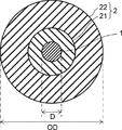
- FIG. 1 is a cross-sectional view of a plastic scintillation fiber according to Embodiment 1.
- FIG. 6 is a cross-sectional view of a plastic scintillation fiber according to Embodiment 2.
- FIG. 1 is a cross-sectional view of a plastic scintillation fiber according to Embodiment 1.
- the plastic scintillation fiber according to the present embodiment includes a core 1 and a clad 2 that covers the outer peripheral surface of the core 1. This plastic scintillation fiber is particularly suitable for radiation detection in a high dose field.
- the core 1 is made of a transparent resin containing a fluorescent agent having ultraviolet light emission.
- a transparent resin containing a fluorescent agent having ultraviolet light emission As the core substrate, for example, an acrylic resin having high heat resistance and easy handling is used.
- the diameter (core diameter) D of the core 1 is 0.2 mm or less. Details of the core base material and the fluorescent agent constituting the core 1 will be described later.
- the clad 2 covering the outer peripheral surface of the core 1 is made of a transparent resin having a refractive index lower than that of the core 1.
- the outer diameter OD of the clad is 0.5 to 2.0 mm.
- the clad base material constituting the clad 2 will be described later.
- the diameter D of the core 1 is 0.2 mm or less, and is thinner than the conventional one. Therefore, the probability that the radiation passes through the core 1 in a high dose field is low, and the dose higher than the conventional one. High resolution in the field.
- the outer diameter OD of the fiber, that is, the clad 2 is 0.5 to 2.0 mm, which is similar to the conventional one, so that the handling property and strength are as excellent as the conventional one. That is, in the scintillation fiber according to the present invention, the resolution is improved by reducing the diameter D of the core 1 which has been considered to be preferably as thick as possible. In addition, strength and handling properties are maintained by increasing the thickness of the clad, which has been considered to be preferably as thin as possible.
- Core substrates include benzyl methacrylate, phenyl methacrylate, cyclohexyl methacrylate, chlorobenzyl methacrylate, 1-phenylethyl methacrylate, 1,2-diphenylethyl methacrylate, diphenylethyl methacrylate, furfuryl methacrylate, 1-phenylcyclohexyl methacrylate, pentachlorophenyl methacrylate A polymer obtained by polymerizing any one of the monomer groups of pentabromophenyl methacrylate, 1-naphthyl methacrylate, 2-naphthyl methacrylate, styrene, ⁇ -methylstyrene, vinyltoluene, methyl methacrylate, benzyl methacrylate, Phenyl methacrylate, cyclohexyl methacrylate, chlorobenzyl methacrylate, 1 Phenylethy
- the refractive index of the core substrate can be in the range of 1.54 to 1.64, for example.
- the refractive index in the present specification is measured using a NAR-3T type manufactured by Atago Co., Ltd. at 25 ° C. and a measurement wavelength of 587.6 nm (d line).
- a general polymerization initiator and a molecular weight modifier may be added.
- the molecular weight modifier is not particularly limited as long as it suppresses the polymerization growth reaction.
- Typical examples of the molecular weight modifier include mercaptans.
- Specific examples of mercaptans include normal octyl mercaptan and normal decanyl mercaptan.
- the clad substrate is a polymer obtained by polymerizing or copolymerizing at least one monomer group of methyl methacrylate, ethyl methacrylate, butyl methacrylate, propyl methacrylate, cyclohexyl methacrylate, methyl acrylate, ethyl acrylate, propyl acrylate, and butyl acrylate. Merge is suitable. Among them, a polymer of methyl methacrylate monomer or a copolymer of methyl methacrylate and another monomer is desirable. Methyl methacrylate has the advantage of being easy to handle because it is highly transparent and easily polymerizes.
- the refractive index of the clad substrate is preferably smaller than the refractive index of the core substrate by 0.05 or more.
- the refractive index of the clad substrate can be, for example, in the range of 1.40 to 1.54.
- the fluorescent agent to be added to the core substrate is selected from those having an ultraviolet light emitting property, having a plurality of aromatic rings, and having a structure capable of resonance.
- Representative fluorescent agents include 2- (4-t-butylphenyl) -5- (4-biphenyl) -1,3,4-oxadiazole (b-PBD), 2- (4-biphenyl)- 5-phenyl-1,3,4-oxadiazole (PBD), paraterphenyl (PTP), paraquaterphenyl (PQP), 2,5-diphenyloxazole (PPO), 1-phenyl-3- (2, 4,6-trimethylphenyl) -2-pyrazoline (PMP), 3-hydroxyflavone (3HF), 4,4′-bis- (2,5-dimethylstyryl) -diphenyl (BDB), 2,5-bis- (5-t-butyl-benzoxazoyl) thiophene (BBOT), 1,4-bis- (2- (5- (5-)
- the effect of the fluorescent agent is to absorb scintillation light emitted from the core substrate, convert it into light having a longer wavelength, and release it. Accordingly, those having light absorption near the emission wavelength of the core substrate are desirable.
- these fluorescent agents include b-PBD, PTP, PQP, and the like. These are referred to as the first fluorescent agent for convenience.
- the emission wavelength of these fluorescent agents is generally lower than the optimum light receiving sensitivity of the detector, it is preferable to convert them to longer wavelengths, and the fluorescence that converts the light emitted by the first fluorescent agent to longer wavelength light.
- An agent may be added. These are called a second fluorescent agent for convenience. Examples of the second fluorescent agent include BBOT, BDB, POPOP, and the like.
- a fluorescent agent having a large absorption wavelength and emission wavelength such as 3HF can be used alone.
- the first fluorescent agent and the second fluorescent agent are present.
- Two types of fluorescent agents are often used.
- a suitable addition amount of the first fluorescent agent is 0.5 to 3.0% by mass, more preferably 0.8 to 2.2% by mass with respect to the core substrate.
- the reason for the relatively high concentration is that the short wavelength scintillation light emitted from the core material is not absorbed by the core base material itself, but must be converted to a longer wavelength within a short distance from the light emitting position. Because. If the amount of the first fluorescent agent added is small, the initial wavelength conversion efficiency deteriorates, so that the final light emission performance cannot be ensured.
- the preferred addition amount of the second fluorescent agent is 0.01 to 0.5% by mass, more preferably 0.02 to 0.3% by mass with respect to the core substrate. If the amount added is too small, the light converted by the first fluorescent agent is efficiently absorbed and cannot be wavelength-converted to a longer wavelength. On the other hand, when the addition amount is too large, not only the cost is increased, but also the transmission loss is deteriorated due to the light absorption loss of the fluorescent agent itself.
- a so-called melt extrusion method can be used in which a plurality of thermoplastic resin pellets having different refractive indexes are simultaneously melt extruded using a multi-die in which a circular shape and a cylindrical shape are combined to form a clad fiber.
- a so-called coating method can be used in which a clad is formed by applying a low refractive index resin on the surface of a monofilament transparent high refractive index resin.
- the melt extrusion method receives shear stress inside the cylinder of the extruder, so that the base material and the fluorescent agent are deteriorated and transparency is deteriorated.
- the coating method can be applied to any fiber having a general core diameter / cladding thickness.
- the monofilament part becomes thin and becomes brittle, and handling properties are deteriorated.
- the clad is thick, the thickness variation increases, and the dimensional accuracy such as roundness deteriorates.
- the clad thickness is 0.4 mm or more, and coating is no longer possible.
- a preform is obtained by inserting a transparent rod-shaped polymer for core (rod for core) made of a high refractive index base material into a cylindrical transparent polymer for cladding (cladding pipe) made of a low refractive index base material.
- a so-called preform heating drawing method is preferable, in which after the production, the drawing is performed by heating from the surroundings with a cylindrical heater. Since the preform heating drawing method is not subjected to shear stress, there is little deterioration of the base material and excellent transparency. Further, since the core rod and the cladding pipe are separately manufactured, the dimensional accuracy of the fiber obtained by subsequent heating drawing is also excellent.
- the core rod is prepared by thermal polymerization in a cylindrical polymerization vessel.
- the polymerization method is preferably spontaneous polymerization by heat, but a minimum amount of a thermal decomposable radical polymerization initiator may be added. Further, a photocleavable radical polymerization initiator may be used in combination.
- a thermal decomposable radical polymerization initiator may be added.
- a photocleavable radical polymerization initiator may be used in combination.
- the molecular weight of the core rod is too low, a draw-down phenomenon that flows under its own weight during heating drawing or a draw resonance phenomenon in which the fiber diameter fluctuates periodically occurs, making it difficult to maintain dimensional accuracy.
- the molecular weight is too high, the viscosity increases, so the heating temperature must be increased, and problems such as coloring and thermal decomposition due to thermal degradation occur. For this reason, you may add a molecular weight modifier as needed.
- the clad pipe can be produced by a method of solidifying polymerization while forming a hollow portion by pressing the monomer against the side surface of the cylindrical container by centrifugal force in a rotating cylindrical container.
- a method of forming a hollow part by drilling a hole in the center part of a rod-shaped polymer with a drill, a method of extruding a thermoplastic resin pellet from a melt extruder equipped with a circular die, and the like, etc. May be used.
- FIG. 2 is a cross-sectional view of the plastic scintillation fiber according to the second embodiment.
- the clad 2 has a multi-cladding structure composed of a single layer.
- the clad 2 has a multi-clad structure including at least two layers of the inner clad 21 and the outer clad 22.
- the inner clad 21 is made of a transparent resin that covers the outer peripheral surface of the core 1 and has a refractive index lower than that of the core 1. Since the clad base material which comprises the inner clad 21 is the same as the clad base material which comprises the clad 2 in Embodiment 1, description is abbreviate
- the outer cladding 22 is made of a resin that covers the outer peripheral surface of the inner cladding 21 and has a lower refractive index than the inner cladding 21. Resins mainly containing fluorine atoms are used. Details of the outer clad base material and the light shielding agent constituting the outer clad 22 will be described later.
- the diameter D of the core 1 is 0.2 mm or less as in the scintillation fiber according to the first embodiment, which is thinner than the conventional one. Therefore, the probability that the radiation passes through the core 1 in the high dose field is low, and the resolution in the high dose field is higher than in the past. Further, since the outer diameter OD of the fiber, that is, the clad 2 is 0.5 to 2.0 mm, which is similar to the conventional one, the handling property and strength are as excellent as the conventional one.
- the numerical aperture NA is higher than that of the scintillation fiber according to the first embodiment. Can be bigger.
- the outer cladding 22 may contain a light shielding agent.
- the outer clad 22 contains a light shielding agent, the scintillation light generated in the outer clad 22 becomes difficult to reach the core 1, and the noise can be reduced.
- the thickness of the inner cladding is preferably several times the transmission wavelength capable of confining light, and is preferably as thin as possible, preferably 1 to 200 ⁇ m, more preferably 5 to 30 ⁇ m.
- outer clad substrate examples include methyl methacrylate, 2,2,2-trifluoroethyl methacrylate, 2,2,3,3-tetrafluoropropyl methacrylate, 2,2,3,3,3-pentafluoropropyl methacrylate, 2 , 2,3,4,4,4-hexafluorobutyl methacrylate, 2,2,3,3,4,4,5,5-octafluoropentyl methacrylate, methyl ⁇ -fluoroacrylate, 2- (trifluoromethyl )
- a polymer obtained by polymerizing or copolymerizing at least one monomer group of methyl propenoate and a mixture of the polymer and polyvinylidene fluoride are suitable.
- the refractive index of the outer clad substrate is preferably 0.05 or more smaller than the refractive index of the inner clad substrate.
- the refractive index of the outer clad substrate can be, for example, in the range of 1.37 to 1.47.
- any organic dye or inorganic pigment may be used as long as the transmittance measured in a form dissolved or dispersed in the outer clad substrate is 50% or less with an optical path length of 10 mm.
- a plurality of light shielding agents may be mixed and used.
- the organic dye include MACROLEX (registered trademark) Green G and Green 5B (manufactured by Lanxess)
- examples of the inorganic pigment include Mitsubishi carbon black (manufactured by Mitsubishi Chemical Corporation).
- Example 1 [Rod for core]
- a styrene monomer 1% by mass of the fluorescent agent paraterphenyl (PTP) and 0.02% by mass of 2,5-bis- (5-tert-butyl-benzoxazoyl) thiophene (BBOT) are dissolved, and this is dissolved in a cylindrical container having an inner diameter of 70 mm.
- the mixture was placed in the inside and thermally polymerized by adjusting the temperature to 70 to 120 ° C.
- the product was taken out from the cylindrical container to obtain a polystyrene rod containing a fluorescent agent.
- This polystyrene rod was drawn by heating to obtain a polystyrene core rod having an outer diameter of 2.5 mm.
- the refractive index of this polystyrene core rod was 1.59 at 25 ° C.
- This PMMA rod was drilled with a drill to produce a PMMA cladding pipe having an outer diameter of 25 mm and an inner diameter of 3 mm.
- the refractive index of this PMMA clad pipe was 1.49 at 25 ° C.
- Preform preparation and heating drawing A preform was prepared by combining a polystyrene core rod and a PMMA cladding pipe. This preform was drawn by heating to obtain a scintillation fiber having an outer diameter of 1 mm. The core diameter was 0.1 mm.
- Example 2 [Rod for core]
- a fluorescent agent paraterphenyl (PTP) and 0.02% by mass of 2,5-bis- (5-tert-butyl-benzoxazoyl) thiophene (BBOT) are dissolved, and this is dissolved in a cylindrical container having an inner diameter of 10 mm.
- the mixture was placed in the inside and thermally polymerized by adjusting the temperature to 70 to 120 ° C.
- the product was taken out from the cylindrical container to obtain a polystyrene core rod containing a fluorescent agent.
- the refractive index of this polystyrene core rod was 1.59 at 25 ° C.
- Preform preparation and heating drawing A preform was prepared by combining a polystyrene core rod, a PMMA inner pipe and a polytrifluoroethyl methacrylate outer pipe. This preform was drawn by heating to obtain a scintillation fiber having an outer diameter of 1 mm. The core diameter was 0.14 mm.
- Example 3 The same procedure as in Example 2 was performed except that 100 ppm (mass ratio) of a dye MACROLEX Green G having a light absorption property as a light-shielding agent was added to a polytrifluoroethyl methacrylate outer clad, and a polystyrene core rod and a PMMA inner pipe An outer pipe made of polytrifluoroethyl methacrylate was obtained.
- the light transmittance of the outer pipe made of polytrifluoroethyl methacrylate was 1% at a thickness of 10 mm as measured according to JIS K7361-1.
- Preform preparation and heating drawing A preform was prepared by combining a polystyrene core rod, a PMMA inner pipe and a polytrifluoroethyl methacrylate outer pipe. This preform was drawn by heating to obtain a scintillation fiber having an outer diameter of 1 mm. The core diameter was 0.14 mm.
- Preform preparation and heating drawing A preform was prepared by combining a polystyrene core rod and a PMMA cladding pipe. This preform was drawn by heating to obtain a scintillation fiber having an outer diameter of 1 mm. The core diameter was 0.97 mm.
- the frequency of scintillation light emission is proportional to the probability that radiation will pass through the core. That is, the light emission frequency changes in proportion to the core diameter ratio.
- the scintillation fiber according to Example 1 has a lower scintillation light generation frequency of 0.1 / 0.97 than the comparative example. Moreover, since the outer diameter is the same, it has equivalent strength and handling properties.
- the scintillation fiber according to Example 2 has a lower scintillation light generation frequency of 0.14 / 0.97 than the comparative example. Moreover, since the outer diameter is the same, it has equivalent strength and handling properties.
- the frequency of scintillation light generation at the core is as low as 0.14 / 0.97 compared to the comparative example.
- the outer diameter is the same, it has equivalent strength and handling properties.
- the outer cladding contains a light shielding agent, noise due to scintillation light generated in the outer cladding is reduced.
Landscapes
- Physics & Mathematics (AREA)
- General Physics & Mathematics (AREA)
- Health & Medical Sciences (AREA)
- Life Sciences & Earth Sciences (AREA)
- High Energy & Nuclear Physics (AREA)
- Molecular Biology (AREA)
- Spectroscopy & Molecular Physics (AREA)
- Optics & Photonics (AREA)
- Measurement Of Radiation (AREA)
- Light Guides In General And Applications Therefor (AREA)
- Optical Fibers, Optical Fiber Cores, And Optical Fiber Bundles (AREA)
Abstract
高線量場における分解能が高く、強度とハンドリング性に優れたプラスチックシンチレーションファイバーを提供する。本発明の一態様に係るプラスチックシンチレーションファイバーは、紫外線発光性を有する蛍光剤を含有するコア(1)と、コア(1)の外周面を被覆すると共に、コア(1)よりも低い屈折率を有するクラッド(2)と、を有するものである。クラッド(2)の外径が0.5~2.0mmであり、コア(1)の径が0.2mm以下であるものである。
Description
本発明はプラスチックシンチレーションファイバー及びその製造方法に関し、特に高線量場での放射線検出に好適なプラスチックシンチレーションファイバー及びその製造方法に関する。
物質に対して外部から圧力、熱、光といったエネルギーを加えると、物質中の電子がある確率で励起状態へと遷移する。この励起された電子が基底状態に戻る際、余剰エネルギーが熱や光として放出される。この中で、放射線(α線、β線、γ線、X線などや陽子などの荷電粒子線)をエネルギーとして加えることによって、余剰エネルギーが光として放出される発光現象を、シンチレーションと呼ぶ。
シンチレーションファイバーは、シンチレーションを利用した放射線検出用の光ファイバーである。シンチレーションファイバーは、シンチレーション性を有する透明基材からなるコアの外周面に、コアよりも低屈折率の透明基材からなるクラッドを被覆したものである。放射線によってコア内で発生した光は、コア/クラッド界面で全反射を繰り返しながら伝播する。最終的に、この光がファイバーの端部に接続されたフォトマルチプライヤ(光電子倍増管)やフォトダイオード等の光検出器によって検知される。
シンチレーションファイバーでは、コア内で発生した光のみが、コアとクラッドとの界面で全反射を繰り返しながらコア内に閉じ込められて伝播する。クラッド内で発生した光は、表面の汚れやキズによって容易にファイバー外へ散失してしまうからである。
コア基材は、シンチレーション性が高い、すなわち放射線により電子励起しやすいものから選定される。励起されやすい電子としては、金属元素中の最外殻電子や不飽和結合のπ電子が代表的である。しかしながら、金属元素の励起光は、自身の光吸収現象により速やかに消失してしまうため、ファイバー用途には適さない。また、透明でシンチレーション性を有する材料として、金属をドープした多成分ガラスなどが知られているが、透明性、加工性、コストなどの点で問題も多い。
このような観点から、シンチレンションファイバーとしては、π電子を含む有機系のプラスチックシンチレーションファイバーが一般的に用いられている。コア基材としては、透明性が高く、π電子を多く含み、放射線に対して安定であるポリスチレンまたはポリビニルトルエンといったベンゼン環を側鎖に有する樹脂が用いられる。
このようなプラスチックシンチレーションファイバーのコアを放射線が通過すると、コア基材のπ電子が励起され、材料固有の波長を有するシンチレーション光が放出される。ポリスチレンやポリビニルトルエンは、主に紫外線領域のシンチレーション光を放出する。例えば、ポリスチレンの発光スペクトルは310nmにピークを持つ。ところが、このような紫外短波長領域の光は、コア基材自身によって吸収されるため、速やかに消失してしまい、光伝送には適さない。
そこで、コア基材に紫外線発光性を有する蛍光剤を添加し、シンチレーション光である紫外短波長領域の光をより長い波長の光に変換した後、ファイバー内を伝送させる方法が一般的である。ここで、コア基材に添加された蛍光剤は、コア基材から放出されたシンチレーション光を吸収し、より長波長の光を再放出する。蛍光剤としては、コア基材の発光波長付近に吸収波長を持つものが望ましい。また、伝送波長を調整するために複数の蛍光剤を用いてもよい。このように長波長へ変換された光が、ファイバー内を伝播し、ファイバー端部に接続された検出器によって検知される。
コア内に蛍光剤等を添加して波長変換するもうひとつの理由は、フォトマルチプライヤなどの光検出器の最大波長感度に合致させるためでもある。一般に、フォトマルチプライヤの感度が最大である波長は430nm付近の青色光であり、近年では微弱光に対応した半導体光検出器(アバランシェフォトダイオード)など、さらに長波長の緑色光に高感度であるものも開発が進んでいる。
コア内に蛍光剤等を添加して波長変換するもうひとつの理由は、フォトマルチプライヤなどの光検出器の最大波長感度に合致させるためでもある。一般に、フォトマルチプライヤの感度が最大である波長は430nm付近の青色光であり、近年では微弱光に対応した半導体光検出器(アバランシェフォトダイオード)など、さらに長波長の緑色光に高感度であるものも開発が進んでいる。
放射線通過位置の特定法としては、飛行時間差測定法すなわちTOF(Time Of Flight)法が知られている(特許文献1~3参照)。TOF法では、シンチレーションファイバーの両端に検出器を設け、放射線により発光した光パルスがファイバーの両端に到達するまでの時間差を検知することにより放射線の通過位置を算出する。
ところで、放射線によるシンチレーションは、放射線と基材を構成する原子との相互作用によって発現する。すなわち、一部は原子間の結合を切断し、一部は原子と衝突して原子を陽子、中性子、電子などに分裂させ、一部は跳ね返されて散乱されて、物質内に2次粒子を発生させる。これら1次粒子や2次粒子が物質を構成する原子やその周囲の電子にエネルギーを与えて、一部の電子は励起される。物質がポリスチレンであれば、最終的にベンゼン環のπ電子が励起され、この励起電子が基底状態に戻るときにシンチレーション光が放出される。すなわち、放射線を検知するためには放射線がシンチレーション性を有するコアを通過する必要がある。
そのため、極微弱な放射線検知の用途に用いられるシンチレーションファイバーでは、コア径を可能な限り太くする必要がある。ここで、ファイバーの外径が大きくなると、剛直となりハンドリング性が悪化したり、湾曲したときに割れやすくなる等の問題がある。また、同一ファイバー径でクラッドが厚くなると、コア径は必然的に小さくなってしまう。そこで、特許文献4では、クラッドの厚さはコアの直径の1~10%、好ましくは2~3%が適当であるとしている。これらの観点から、クラッドを含めたファイバーの外径を0.5~2.0mmとし、コア径を外径の97~98%、すなわち0.485~1.96mmとするのが一般的であった。
しかしながら、放射線量の高い、いわゆる高線量場では、極短時間のうちに複数の放射線が一本のコアを通過することがある。ここで、シンチレーション光からなる光パルスが両端の検出器に到達する前に、次の放射線通過によるシンチレーション光の光パルスが発生してしまうと、前後のシンチレーション光を分離することができない。
すなわち、TOF法における位置の特定に必要な時間差に対して無視できない程の高い頻度で複数の放射線がコアを通過するような高線量場では、個々の放射線の情報を分離することはできない。
高線量場としては、例えば粒子フルエンス率が1×10⁵[1/(m2・s)]以上のものが挙げられる。高線量場では上記問題が生じ得るため、従来のシンチレーションファイバーでは用をなさなかった。ここで、粒子フルエンス率とは、照射場の単位面積を単位時間あたりに通過する粒子(放射線)の数である。
高線量場としては、例えば粒子フルエンス率が1×10⁵[1/(m2・s)]以上のものが挙げられる。高線量場では上記問題が生じ得るため、従来のシンチレーションファイバーでは用をなさなかった。ここで、粒子フルエンス率とは、照射場の単位面積を単位時間あたりに通過する粒子(放射線)の数である。
このような高線量場では、コア径を小さくし、放射線がコアを通過する頻度を少なくすれば良い。ところが、従来のコア径比率を保持したままでコア径を細くすると、必然的にシンチレーションファイバーそのものの外径が細くなるため、強度が低下し、取り扱いの際に切れやすくなる問題があった。また、検出器にセットしにくい等、ハンドリング性に劣る問題があった。
本発明は、上記に鑑みなされたものであって、高線量場における分解能が高く、強度とハンドリング性に優れたプラスチックシンチレーションファイバーを提供することを目的とする。
本発明の一態様に係るプラスチックシンチレーションファイバーは、
紫外線発光性を有する蛍光剤を含有するコアと、前記コアの外周面を被覆すると共に、前記コアよりも低い屈折率を有するクラッドと、を有するプラスチックシンチレーションファイバーであって、
前記クラッドの外径が0.5~2.0mmであり、前記コアの径が0.2mm以下であるものである。
コアの径が0.2mm以下であり、従来よりも細いため、高線量場において放射線がコアを通過する確率が低くなり、従来よりも分解能が高い。また、クラッドの外径が、0.5~2.0mmであり、ハンドリング性や強度が従来と同等に優れている。
紫外線発光性を有する蛍光剤を含有するコアと、前記コアの外周面を被覆すると共に、前記コアよりも低い屈折率を有するクラッドと、を有するプラスチックシンチレーションファイバーであって、
前記クラッドの外径が0.5~2.0mmであり、前記コアの径が0.2mm以下であるものである。
コアの径が0.2mm以下であり、従来よりも細いため、高線量場において放射線がコアを通過する確率が低くなり、従来よりも分解能が高い。また、クラッドの外径が、0.5~2.0mmであり、ハンドリング性や強度が従来と同等に優れている。
前記クラッドが、インナークラッドと、前記インナークラッドの外周面を被覆すると共に、前記インナークラッドよりも低い屈折率を有するアウタークラッドとを含むマルチクラッド構造を有していることが好ましい。開口数を大きくすることができる。
また、前記アウタークラッドが、遮光剤を含有することが好ましい。クラッドで発生するシンチレーション光に起因するノイズを低減することができる。
本発明の一態様に係るプラスチックシンチレーションファイバーの製造方法は、
紫外線発光性を有する蛍光剤を含有するコアと、前記コアの外周面を被覆するクラッドと、を備えたプラスチックシンチレーションファイバーの製造方法であって、
紫外線発光性を有する蛍光剤を含有する樹脂からなる棒状のコア用ロッドを、前記コア用ロッドよりも低い屈折率を有する樹脂からなる円筒状のクラッド用パイプに挿入してプリフォームを作製する工程と、
前記プリフォームを加熱しつつ線引きする工程と、を備え、
線引きする工程において、前記クラッドの外径を0.5~2.0mmとし、前記コアの径を0.2mm以下とするものである。
コアの径が0.2mm以下であり、従来よりも細いため、高線量場において放射線がコアを通過する確率が低くなり、従来よりも分解能が高い。また、クラッドの外径が、0.5~2.0mmであり、ハンドリング性や強度が従来と同等に優れている。
紫外線発光性を有する蛍光剤を含有するコアと、前記コアの外周面を被覆するクラッドと、を備えたプラスチックシンチレーションファイバーの製造方法であって、
紫外線発光性を有する蛍光剤を含有する樹脂からなる棒状のコア用ロッドを、前記コア用ロッドよりも低い屈折率を有する樹脂からなる円筒状のクラッド用パイプに挿入してプリフォームを作製する工程と、
前記プリフォームを加熱しつつ線引きする工程と、を備え、
線引きする工程において、前記クラッドの外径を0.5~2.0mmとし、前記コアの径を0.2mm以下とするものである。
コアの径が0.2mm以下であり、従来よりも細いため、高線量場において放射線がコアを通過する確率が低くなり、従来よりも分解能が高い。また、クラッドの外径が、0.5~2.0mmであり、ハンドリング性や強度が従来と同等に優れている。
前記クラッド用パイプを、インナークラッド用パイプと、前記インナークラッド用パイプの外周面を被覆すると共に、前記インナークラッド用パイプよりも低い屈折率を有する樹脂からなるアウタークラッド用パイプとから構成することが好ましい。開口数を大きくすることができる。
前記アウタークラッド用パイプを、遮光剤を含有する樹脂から構成することが好ましい。クラッドで発生するシンチレーション光に起因するノイズを低減することができる。
本発明により、高線量場における分解能が高く、強度とハンドリング性に優れたプラスチックシンチレーションファイバーを提供することができる。
以下、本発明を適用した具体的な実施の形態について、図面を参照しながら詳細に説明する。ただし、本発明が以下の実施の形態に限定される訳ではない。また、説明を明確にするため、以下の記載及び図面は、適宜、簡略化されている。
(実施の形態1)
図1を参照して、本発明の実施の形態1に係るプラスチックシンチレーションファイバーについて説明する。図1は、実施の形態1に係るプラスチックシンチレーションファイバーの断面図である。
図1に示すように、本実施の形態に係るプラスチックシンチレーションファイバーは、コア1と、コア1の外周面を被覆するクラッド2と、を備えている。このプラスチックシンチレーションファイバーは、特に高線量場での放射線検出に好適である。
図1を参照して、本発明の実施の形態1に係るプラスチックシンチレーションファイバーについて説明する。図1は、実施の形態1に係るプラスチックシンチレーションファイバーの断面図である。
図1に示すように、本実施の形態に係るプラスチックシンチレーションファイバーは、コア1と、コア1の外周面を被覆するクラッド2と、を備えている。このプラスチックシンチレーションファイバーは、特に高線量場での放射線検出に好適である。
コア1は、紫外線発光性を有する蛍光剤を含んだ透明樹脂からなる。コア基材としては、例えば耐熱性が高くて取り扱い容易なアクリル系樹脂が用いられる。コア1の径(コア径)Dは0.2mm以下である。コア1を構成するコア基材及び蛍光剤の詳細については後述する。
コア1の外周面を被覆するクラッド2は、コア1よりも低い屈折率を有する透明樹脂からなる。クラッドの外径ODは0.5~2.0mmである。クラッド2を構成するクラッド基材については後述する。
コア1の外周面を被覆するクラッド2は、コア1よりも低い屈折率を有する透明樹脂からなる。クラッドの外径ODは0.5~2.0mmである。クラッド2を構成するクラッド基材については後述する。
本実施の形態に係るシンチレーションファイバーでは、コア1の径Dが0.2mm以下であり、従来よりも細いため、高線量場において放射線がコア1を通過する確率が低くなり、従来よりも高線量場における分解能が高い。また、ファイバーすなわちクラッド2の外径ODが、0.5~2.0mmであり、従来と同程度であるため、ハンドリング性や強度が従来と同等に優れている。すなわち、本発明に係るシンチレーションファイバーでは、従来はできる限り太い方が好ましいとされてきたコア1の径Dを細くすることにより分解能を向上させている。また、従来はできる限り薄いほうが好ましいとされていたクラッドを厚くすることにより、強度及びハンドリング性を維持している。
[コア基材]
コア基材としては、ベンジルメタクリレート、フェニルメタクリレート、シクロヘキシルメタクリレート、クロロベンジルメタクリレート、1-フェニルエチルメタクリレート、1,2-ジフェニルエチルメタクリレート、ジフェニルエチルメタクリレート、フルフリルメタクリレート、1-フェニルシクロヘキシルメタクリレート、ペンタクロロフェニルメタクリレート、ペンタブロモフェニルメタクリレート、1-ナフチルメタクリレート、2-ナフチルメタクリレート、スチレン、α-メチルスチレン、ビニルトルエンのモノマー群のうち、いずれか1種類を重合して得られる重合体及びメチルメタクリレート、ベンジルメタクリレート、フェニルメタクリレート、シクロヘキシルメタクリレート、クロロベンジルメタクリレート、1-フェニルエチルメタクリレート、1,2-ジフェニルエチルメタクリレート、ジフェニルエチルメタクリレート、フルフリルメタクリレート、1-フェニルシクロヘキシルメタクリレート、ペンタクロロフェニルメタクリレート、ペンタブロモフェニルメタクリレート、1-ナフチルメタクリレート、2-ナフチルメタクリレート、スチレン、α-メチルスチレン、ビニルトルエンのモノマー群のうち、いずれか2種類以上のモノマーを共重合して得られる共重合体が適している。
コア基材の屈折率は、例えば1.54~1.64の範囲とすることができる。なお、本明細書における屈折率は、アタゴ社製NAR-3T型を用いて、25℃にて測定波長587.6nm(d線)で測定したものである。
コア基材としては、ベンジルメタクリレート、フェニルメタクリレート、シクロヘキシルメタクリレート、クロロベンジルメタクリレート、1-フェニルエチルメタクリレート、1,2-ジフェニルエチルメタクリレート、ジフェニルエチルメタクリレート、フルフリルメタクリレート、1-フェニルシクロヘキシルメタクリレート、ペンタクロロフェニルメタクリレート、ペンタブロモフェニルメタクリレート、1-ナフチルメタクリレート、2-ナフチルメタクリレート、スチレン、α-メチルスチレン、ビニルトルエンのモノマー群のうち、いずれか1種類を重合して得られる重合体及びメチルメタクリレート、ベンジルメタクリレート、フェニルメタクリレート、シクロヘキシルメタクリレート、クロロベンジルメタクリレート、1-フェニルエチルメタクリレート、1,2-ジフェニルエチルメタクリレート、ジフェニルエチルメタクリレート、フルフリルメタクリレート、1-フェニルシクロヘキシルメタクリレート、ペンタクロロフェニルメタクリレート、ペンタブロモフェニルメタクリレート、1-ナフチルメタクリレート、2-ナフチルメタクリレート、スチレン、α-メチルスチレン、ビニルトルエンのモノマー群のうち、いずれか2種類以上のモノマーを共重合して得られる共重合体が適している。
コア基材の屈折率は、例えば1.54~1.64の範囲とすることができる。なお、本明細書における屈折率は、アタゴ社製NAR-3T型を用いて、25℃にて測定波長587.6nm(d線)で測定したものである。
重合に際しては、一般的な重合開始剤及び分子量調整剤を添加しても良い。
分子量調整剤は、重合成長反応を抑制するものであれば特に制限はない。代表的な分子量調整剤としてはメルカプタン類が挙げられる。具体的にはメルカプタンとしてノルマルオクチルメルカプタン、ノルマルデカニルメルカプタン等がある。
分子量調整剤は、重合成長反応を抑制するものであれば特に制限はない。代表的な分子量調整剤としてはメルカプタン類が挙げられる。具体的にはメルカプタンとしてノルマルオクチルメルカプタン、ノルマルデカニルメルカプタン等がある。
[クラッド基材]
クラッド基材としては、メチルメタクリレート、エチルメタクリレート、ブチルメタクリレート、プロピルメタクリレート、シクロヘキシルメタクリレート、メチルアクリレート、エチルアクリレート、プロピルアクリレート、ブチルアクリレートのモノマー群のうち1種類以上を重合または共重合して得られる重合体が適している。中でも、メチルメチクリレートモノマーの重合体またはメチルメタクリレートと他のモノマーの共重合体が望ましい。メチルメタクリレートは透明性が高く、容易に重合するため取り扱いしやすい利点がある。重合に際しては、一般的な重合開始剤及び分子量調整剤を添加しても良い。
クラッド基材の屈折率は、コア基材の屈折率よりも0.05以上小さいことが好ましい。クラッド基材の屈折率は、例えば1.40~1.54の範囲とすることができる。
クラッド基材としては、メチルメタクリレート、エチルメタクリレート、ブチルメタクリレート、プロピルメタクリレート、シクロヘキシルメタクリレート、メチルアクリレート、エチルアクリレート、プロピルアクリレート、ブチルアクリレートのモノマー群のうち1種類以上を重合または共重合して得られる重合体が適している。中でも、メチルメチクリレートモノマーの重合体またはメチルメタクリレートと他のモノマーの共重合体が望ましい。メチルメタクリレートは透明性が高く、容易に重合するため取り扱いしやすい利点がある。重合に際しては、一般的な重合開始剤及び分子量調整剤を添加しても良い。
クラッド基材の屈折率は、コア基材の屈折率よりも0.05以上小さいことが好ましい。クラッド基材の屈折率は、例えば1.40~1.54の範囲とすることができる。
[蛍光剤]
コア基材に添加する蛍光剤は、紫外線発光性であり、複数個の芳香環をもち、かつ共鳴が可能な構造を有するものの中から選ばれる。代表的な蛍光剤としては、2-(4-t-ブチルフェニル)-5-(4-ビフェニル)-1,3,4-オキサジアゾール(b-PBD)、2-(4-ビフェニル)-5-フェニル-1,3,4-オキサジアゾール(PBD)、パラターフェニル(PTP)、パラクォーターフェニル(PQP)、2,5-ジフェニルオキサゾール(PPO)、1-フェニル-3-(2,4,6-トリメチルフェニル)-2-ピラゾリン(PMP)、3-ヒドロキシフラボン(3HF)、4,4‘-ビス-(2,5-ジメチルスチリル)-ジフェニル(BDB)、2,5-ビス-(5-t-ブチル-ベンゾキサゾイル)チオフェン(BBOT)、1,4-ビス-(2-(5-フェニロキサゾリル))ベンゼン(POPOP)、1,4-ビス-(4-メチル-5-フェニル-2-オキサゾリル)ベンゼン(DMPOPOP)、1,4-ジフェニル-1,3-ブタジエン(DPB)、1,6-ジフェニル-1,3,5-ヘキサトリエン(DPH)等が挙げられる。
これらは単独で使用してもよいし、複数の蛍光剤を組み合わせて使用してもかまわない。
コア基材に添加する蛍光剤は、紫外線発光性であり、複数個の芳香環をもち、かつ共鳴が可能な構造を有するものの中から選ばれる。代表的な蛍光剤としては、2-(4-t-ブチルフェニル)-5-(4-ビフェニル)-1,3,4-オキサジアゾール(b-PBD)、2-(4-ビフェニル)-5-フェニル-1,3,4-オキサジアゾール(PBD)、パラターフェニル(PTP)、パラクォーターフェニル(PQP)、2,5-ジフェニルオキサゾール(PPO)、1-フェニル-3-(2,4,6-トリメチルフェニル)-2-ピラゾリン(PMP)、3-ヒドロキシフラボン(3HF)、4,4‘-ビス-(2,5-ジメチルスチリル)-ジフェニル(BDB)、2,5-ビス-(5-t-ブチル-ベンゾキサゾイル)チオフェン(BBOT)、1,4-ビス-(2-(5-フェニロキサゾリル))ベンゼン(POPOP)、1,4-ビス-(4-メチル-5-フェニル-2-オキサゾリル)ベンゼン(DMPOPOP)、1,4-ジフェニル-1,3-ブタジエン(DPB)、1,6-ジフェニル-1,3,5-ヘキサトリエン(DPH)等が挙げられる。
これらは単独で使用してもよいし、複数の蛍光剤を組み合わせて使用してもかまわない。
以下に、蛍光剤の組み合わせ例について説明する。
蛍光剤の効能は、コア基材が発するシンチレーション光を吸収し、より長波長の光へと変換して放出することにある。従って、コア基材の発光波長付近に光吸収を持つものが望ましい。これらの蛍光剤の例としてはb-PBDやPTP、PQP等が挙げられる。これらを便宜的に第一蛍光剤と称する。
蛍光剤の効能は、コア基材が発するシンチレーション光を吸収し、より長波長の光へと変換して放出することにある。従って、コア基材の発光波長付近に光吸収を持つものが望ましい。これらの蛍光剤の例としてはb-PBDやPTP、PQP等が挙げられる。これらを便宜的に第一蛍光剤と称する。
ただし、これらの蛍光剤の発光波長は一般に検出器の最適受光感度よりも低いため、より長波長に変換させることが好ましく、第一蛍光剤が発した光をより長波長の光へ変換する蛍光剤を加えることがある。これらを便宜的に第二蛍光剤と称する。第二蛍光剤の例としてはBBOT、BDB、POPOP等が挙げられる。
例えば、3HFのような吸収波長と発光波長が大きく離れている蛍光剤は単独で用いることができるが、このような蛍光剤は限られたものしか存在しないので、第一蛍光剤と第二蛍光剤の2種類の蛍光剤を用いることが多い。
第一の蛍光剤の好適添加量は、コア基材に対して0.5~3.0質量%であり、より好ましくは0.8~2.2質量%である。比較的高濃度とする理由は、コア材から発光した短波長のシンチレーション光をコア基材自身で吸収されることなく、その発光位置から短い距離内で、より長波長に波長変換させなければならないからである。第一蛍光剤の添加量が少ないと、最初の波長変換効率が悪化するので最終的な発光性能が確保できない。逆に、過度に添加することは蛍光剤のコア材への溶解性において困難であったり、コスト高になるばかりか、伝送損失悪化の原因にもなる。
また、第二蛍光剤の好適添加量は、コア基材に対して0.01~0.5質量%であり、より好ましくは0.02~0.3質量%である。添加量が少な過ぎると、第一蛍光剤で変換した光を効率よく吸収してより長い波長に波長変換することができない。逆に、添加量が多過ぎると、コストアップに繋がるだけでなく、蛍光剤自身の光吸収損失により伝送損失が悪化する。
第一の蛍光剤の好適添加量は、コア基材に対して0.5~3.0質量%であり、より好ましくは0.8~2.2質量%である。比較的高濃度とする理由は、コア材から発光した短波長のシンチレーション光をコア基材自身で吸収されることなく、その発光位置から短い距離内で、より長波長に波長変換させなければならないからである。第一蛍光剤の添加量が少ないと、最初の波長変換効率が悪化するので最終的な発光性能が確保できない。逆に、過度に添加することは蛍光剤のコア材への溶解性において困難であったり、コスト高になるばかりか、伝送損失悪化の原因にもなる。
また、第二蛍光剤の好適添加量は、コア基材に対して0.01~0.5質量%であり、より好ましくは0.02~0.3質量%である。添加量が少な過ぎると、第一蛍光剤で変換した光を効率よく吸収してより長い波長に波長変換することができない。逆に、添加量が多過ぎると、コストアップに繋がるだけでなく、蛍光剤自身の光吸収損失により伝送損失が悪化する。
[製造方法]
シンチレーションファイバーの製造方法については、特に制限はない。例えば、円形と筒形を複合させたマルチダイを用いて屈折率の異なる複数の熱可塑性樹脂ペレットを同時に溶融押出してクラッド付きファイバーを成形するいわゆる溶融押出法を用いることができる。あるいは、モノフィラメント状の透明高屈折率樹脂の表面に低屈折率樹脂を塗布してクラッドを形成するいわゆるコーティング法を用いることができる。
シンチレーションファイバーの製造方法については、特に制限はない。例えば、円形と筒形を複合させたマルチダイを用いて屈折率の異なる複数の熱可塑性樹脂ペレットを同時に溶融押出してクラッド付きファイバーを成形するいわゆる溶融押出法を用いることができる。あるいは、モノフィラメント状の透明高屈折率樹脂の表面に低屈折率樹脂を塗布してクラッドを形成するいわゆるコーティング法を用いることができる。
しかしながら、溶融押出法は、押出機のシリンダー内部でせん断応力を受けるため基材や蛍光剤が劣化し透明性が悪化する。また、コーティング法は、一般的なコア径/クラッド厚のファイバーであれば適用できるが、本発明ではモノフィラメント部が細くなるため脆弱となりハンドリング性が悪化する。さらに、クラッドが厚いため、厚みのバラツキが大きくなり、真円性などの寸法精度が悪化する。特に、外径1mm以上のファイバーでは、クラッド厚が0.4mm以上となり、もはやコーティングできなくなってしまう。
そこで、低屈折率基材からなるクラッド用の円筒状透明重合体(クラッド用パイプ)に、高屈折率基材からなるコア用の透明棒状重合体(コア用ロッド)を挿入してプリフォームを作製した後、筒状のヒーターで周囲から加熱して線引きする、いわゆるプリフォーム加熱線引き法が好ましい。
プリフォーム加熱線引き法は、せん断応力を受けないため、基材の劣化が少なく、透明性に優れる。また、コア用ロッドとクラッド用パイプとを別々に作製するため、その後の加熱線引きにより得られるファイバーの寸法精度にも優れている。
プリフォーム加熱線引き法は、せん断応力を受けないため、基材の劣化が少なく、透明性に優れる。また、コア用ロッドとクラッド用パイプとを別々に作製するため、その後の加熱線引きにより得られるファイバーの寸法精度にも優れている。
ここで、コア用ロッドは、円筒状の重合容器に入れて熱重合によって作製するのが望ましい。重合方法は熱による自発的重合が好ましいが、最小限量の熱解裂型ラジカル重合開始剤を添加してもよい。さらに、光解裂型ラジカル重合開始剤を併用してもよい。また、コア用ロッドは、分子量が低過ぎると、加熱線引きの際に自重で流れ落ちるドローダウン現象やファイバー径が周期的に変動するドローレゾナンス現象が起こり、寸法精度が保持し難くなる。逆に、分子量が高過ぎると、粘度が高くなるため、加熱温度を高くする必要があり、熱劣化による着色や熱分解といった問題が発生する。このため、必要に応じて、分子量調整剤を添加してもよい。
また、クラッド用パイプは、回転する円筒容器中で遠心力によってモノマーを円筒容器側面に押し付けるようにして中空部を形成させながら重合固化させる方法により作製することができる。あるいは、ロッド状の重合体の軸中心部にドリル等で穴を開けて中空部を形成する方法や、円形ダイを装着した溶融押出機より熱可塑性樹脂ペレットを押出してパイプ状に成形する方法などを用いてもよい。
(実施の形態2)
次に、図2を参照して、本発明の実施の形態2に係るプラスチックシンチレーションファイバーについて説明する。図2は、実施の形態2に係るプラスチックシンチレーションファイバーの断面図である。
次に、図2を参照して、本発明の実施の形態2に係るプラスチックシンチレーションファイバーについて説明する。図2は、実施の形態2に係るプラスチックシンチレーションファイバーの断面図である。
図2に示すように、実施の形態1に係るプラスチックシンチレーションファイバーでは、クラッド2が単層からなるマルチクラッド構造を有している。これに対し、実施の形態2に係るプラスチックシンチレーションファイバーでは、クラッド2が、インナークラッド21及びアウタークラッド22の2層を少なくとも含むマルチクラッド構造を有している。
インナークラッド21は、コア1の外周面を被覆すると共に、コア1よりも低い屈折率を有する透明樹脂からなる。インナークラッド21を構成するクラッド基材は、実施の形態1におけるクラッド2を構成するクラッド基材と同じであるため、説明を省略する。
アウタークラッド22は、インナークラッド21の外周面を被覆すると共に、インナークラッド21よりも低い屈折率を有する樹脂からなる。主としてフッ素原子を含む樹脂が用いられる。アウタークラッド22を構成するアウタークラッド基材、遮光剤の詳細については後述する。
実施の形態2に係るシンチレーションファイバーでは、実施の形態1に係るシンチレーションファイバーと同様にコア1の径Dが0.2mm以下であり、従来よりも細い。そのため高線量場において放射線がコア1を通過する確率が低くなり、従来よりも高線量場における分解能が高い。また、ファイバーすなわちクラッド2の外径ODが0.5~2.0mmであり、従来と同程度であるため、ハンドリング性や強度が従来と同等に優れている。
さらに、クラッド2が、インナークラッド21とインナークラッド21よりも低い屈折率を有するアウタークラッド22とを含むマルチクラッド構造を有しているため、実施の形態1に係るシンチレーションファイバーよりも開口数NAを大きくすることができる。
さらに、クラッド2が、インナークラッド21とインナークラッド21よりも低い屈折率を有するアウタークラッド22とを含むマルチクラッド構造を有しているため、実施の形態1に係るシンチレーションファイバーよりも開口数NAを大きくすることができる。
ところで、プラスチックシンチレーションファイバーでは、放射線によって分子結合の軸となるσ電子が励起され、この電子が基底状態に戻る際にシンチレーション光が放出されることがある。この発光はコア1とクラッド2のいずれでも起こり得る。ここで、クラッド2から放出されたシンチレーション光がコア1を通過し、コア1の蛍光剤が発光する場合がある。この発光は、コア1に到達した放射線以外によるイレギュラーな発光であり、好ましくない。このようなクラッド2での発光によるコア1の蛍光剤の発光は、コア1での発光によるコア1の蛍光剤の発光に対してタイムラグが発生し、ノイズとなるからである。その結果、放射線通過位置の特定精度が低下する。
上述の通り、実施の形態2に係るプラスチックシンチレーションファイバーでは、アウタークラッド22が、遮光剤を含有していてもよい。アウタークラッド22が遮光剤を含有することにより、アウタークラッド22で発生するシンチレーション光がコア1に到達し難くなり、上記ノイズを低減することができる。その際、インナークラッドの厚さは光を閉じ込めることができる伝送波長の数倍以上で、しかもできるだけ薄いことが好ましく、1~200μm、より好ましくは5~30μmであることが好ましい。
[アウタークラッド基材]
アウタークラッド基材としては、メチルメタクリレート、2,2,2-トリフルオロエチルメタクリレート、2,2,3,3-テトラフルオロプロピルメタクリレート、2,2,3,3,3-ペンタフルオロプロピルメタクリレート、2,2,3,4,4,4-ヘキサフルオロブチルメタクリレート,2,2,3,3,4,4,5,5-オクタフルオロペンチルメタクリレート、α-フルオロアクリル酸メチル、2-(トリフルオロメチル)プロペン酸メチルのモノマー群のうち1種類以上を重合または共重合して得られる重合体及び、前記重合体とポリフッ化ビニリデンの混合物が適している。中でも、2,2,2-トリフルオロエチルメタクリレートポリマーとポリフッ化ビニリデンの混合物が望ましい。
アウタークラッド基材の屈折率は、インナークラッド基材の屈折率よりも0.05以上小さいことが好ましい。アウタークラッド基材の屈折率は、例えば1.37~1.47の範囲とすることができる。
アウタークラッド基材としては、メチルメタクリレート、2,2,2-トリフルオロエチルメタクリレート、2,2,3,3-テトラフルオロプロピルメタクリレート、2,2,3,3,3-ペンタフルオロプロピルメタクリレート、2,2,3,4,4,4-ヘキサフルオロブチルメタクリレート,2,2,3,3,4,4,5,5-オクタフルオロペンチルメタクリレート、α-フルオロアクリル酸メチル、2-(トリフルオロメチル)プロペン酸メチルのモノマー群のうち1種類以上を重合または共重合して得られる重合体及び、前記重合体とポリフッ化ビニリデンの混合物が適している。中でも、2,2,2-トリフルオロエチルメタクリレートポリマーとポリフッ化ビニリデンの混合物が望ましい。
アウタークラッド基材の屈折率は、インナークラッド基材の屈折率よりも0.05以上小さいことが好ましい。アウタークラッド基材の屈折率は、例えば1.37~1.47の範囲とすることができる。
[遮光剤]
遮光剤としては、アウタークラッド基材に溶解または分散させた形態で測定した透過率が10mmの光路長で50%以下となるものであれば、有機染料、無機顔料のいずれを用いてもよい。また、複数の遮光剤を混ぜて使用してもよい。有機染料としては、MACROLEX(登録商標) Green G、Green 5B (Lanxess社製)、無機顔料としては、三菱カーボンブラック(三菱化学社製)等が挙げられる。
遮光剤としては、アウタークラッド基材に溶解または分散させた形態で測定した透過率が10mmの光路長で50%以下となるものであれば、有機染料、無機顔料のいずれを用いてもよい。また、複数の遮光剤を混ぜて使用してもよい。有機染料としては、MACROLEX(登録商標) Green G、Green 5B (Lanxess社製)、無機顔料としては、三菱カーボンブラック(三菱化学社製)等が挙げられる。
以下、本発明を実施例によりさらに詳細に説明するが、本発明は係る実施例により何ら限定されない。
<実施例1>
[コア用ロッド]
スチレンモノマーに蛍光剤パラターフェニル(PTP)1質量%及び2,5-ビス-(5-t-ブチル-ベンゾキサゾイル)チオフェン(BBOT)0.02質量%を溶解し、これを内径70mmの円筒容器中にいれ、70~120℃に温度調節して熱重合させた。円筒容器から取り出し、蛍光剤を含んだポリスチレン製ロッドを得た。このポリスチレン製ロッドを加熱線引きし、外径2.5mmのポリスチレン製コア用ロッドを得た。このポリスチレン製コア用ロッドの屈折率は25℃で1.59であった。
[コア用ロッド]
スチレンモノマーに蛍光剤パラターフェニル(PTP)1質量%及び2,5-ビス-(5-t-ブチル-ベンゾキサゾイル)チオフェン(BBOT)0.02質量%を溶解し、これを内径70mmの円筒容器中にいれ、70~120℃に温度調節して熱重合させた。円筒容器から取り出し、蛍光剤を含んだポリスチレン製ロッドを得た。このポリスチレン製ロッドを加熱線引きし、外径2.5mmのポリスチレン製コア用ロッドを得た。このポリスチレン製コア用ロッドの屈折率は25℃で1.59であった。
[クラッド用パイプ]
メチルメタクリレートモノマーに重合開始剤(日油社製パーオクタO(登録商標)(PO-O):0.05質量%、日油社製パーヘキサV(登録商標)(PH-V):0.05質量%)と分子量を調整するための連鎖移動剤n-オクチルメルカプタン(n-OM:0.25質量%)を添加した。これを内径25mmの円筒容器に入れ、70~120℃で加熱重合させてポリメチルメタクリレート(PMMA)製ロッドを得た。このPMMA製ロッドの円心部をドリルで穴あけ加工し、外径25mmで内径3mmのPMMA製クラッド用パイプを作製した。このPMMA製クラッド用パイプの屈折率は25℃で1.49であった。
メチルメタクリレートモノマーに重合開始剤(日油社製パーオクタO(登録商標)(PO-O):0.05質量%、日油社製パーヘキサV(登録商標)(PH-V):0.05質量%)と分子量を調整するための連鎖移動剤n-オクチルメルカプタン(n-OM:0.25質量%)を添加した。これを内径25mmの円筒容器に入れ、70~120℃で加熱重合させてポリメチルメタクリレート(PMMA)製ロッドを得た。このPMMA製ロッドの円心部をドリルで穴あけ加工し、外径25mmで内径3mmのPMMA製クラッド用パイプを作製した。このPMMA製クラッド用パイプの屈折率は25℃で1.49であった。
[プリフォーム作製及び加熱線引き]
ポリスチレン製コア用ロッドとPMMA製クラッド用パイプとを組み合わせてプリフォームを作製した。このプリフォームを加熱線引きし、外径1mmのシンチレーションファイバーを得た。コア径は0.1mmであった。
ポリスチレン製コア用ロッドとPMMA製クラッド用パイプとを組み合わせてプリフォームを作製した。このプリフォームを加熱線引きし、外径1mmのシンチレーションファイバーを得た。コア径は0.1mmであった。
<実施例2>
[コア用ロッド]
スチレンモノマーに蛍光剤パラターフェニル(PTP)1質量%及び2,5-ビス-(5-t-ブチル-ベンゾキサゾイル)チオフェン(BBOT)0.02質量%を溶解し、これを内径10mmの円筒容器中にいれ、70~120℃に温度調節して熱重合させた。円筒容器から取り出し、蛍光剤を含んだポリスチレン製コア用ロッドを得た。このポリスチレン製コア用ロッドの屈折率は25℃で1.59であった。
[コア用ロッド]
スチレンモノマーに蛍光剤パラターフェニル(PTP)1質量%及び2,5-ビス-(5-t-ブチル-ベンゾキサゾイル)チオフェン(BBOT)0.02質量%を溶解し、これを内径10mmの円筒容器中にいれ、70~120℃に温度調節して熱重合させた。円筒容器から取り出し、蛍光剤を含んだポリスチレン製コア用ロッドを得た。このポリスチレン製コア用ロッドの屈折率は25℃で1.59であった。
[インナークラッド用パイプ]
メチルメタクリレートモノマーに重合開始剤(PO-O:0.05質量%、PH-V:0.05質量%)と分子量を調整するための連鎖移動剤n-オクチルメルカプタン(n-OM:0.25質量%)を添加した。これを内径16mmの円筒容器に入れ、熱媒中で軸方向に回転させながら加熱、重合させて、外径16mmで内径11mmのポリメチルメタクリレート(PMMA)製インナーパイプを得た。このPMMA製インナーパイプの屈折率は25℃で1.49であった。
メチルメタクリレートモノマーに重合開始剤(PO-O:0.05質量%、PH-V:0.05質量%)と分子量を調整するための連鎖移動剤n-オクチルメルカプタン(n-OM:0.25質量%)を添加した。これを内径16mmの円筒容器に入れ、熱媒中で軸方向に回転させながら加熱、重合させて、外径16mmで内径11mmのポリメチルメタクリレート(PMMA)製インナーパイプを得た。このPMMA製インナーパイプの屈折率は25℃で1.49であった。
[アウタークラッド用パイプ]
トリフルオロエチルメタクリレート(3FMA)モノマーに重合開始剤(PO-O:0.05質量%、PH-V:0.05質量%)と分子量を調整するための連鎖移動剤n-オクチルメルカプタン(n-OM:0.025質量%)を添加した。これを内径70mmの円筒容器に入れ、熱媒中で軸方向に回転させながら加熱、重合させて外径70mmで内径17mmのポリトリフルオロエチルメタクリレート製アウターパイプを得た。このポリトリフルオロエチルメタクリレート製アウターパイプの屈折率は25℃で1.42であった。
トリフルオロエチルメタクリレート(3FMA)モノマーに重合開始剤(PO-O:0.05質量%、PH-V:0.05質量%)と分子量を調整するための連鎖移動剤n-オクチルメルカプタン(n-OM:0.025質量%)を添加した。これを内径70mmの円筒容器に入れ、熱媒中で軸方向に回転させながら加熱、重合させて外径70mmで内径17mmのポリトリフルオロエチルメタクリレート製アウターパイプを得た。このポリトリフルオロエチルメタクリレート製アウターパイプの屈折率は25℃で1.42であった。
[プリフォーム作製及び加熱線引き]
ポリスチレン製コア用ロッドとPMMA製インナーパイプとポリトリフルオロエチルメタクリレート製アウターパイプとを組み合わせてプリフォームを作製した。このプリフォームを加熱線引きし、外径1mmのシンチレーションファイバーを得た。コア径は0.14mmであった。
ポリスチレン製コア用ロッドとPMMA製インナーパイプとポリトリフルオロエチルメタクリレート製アウターパイプとを組み合わせてプリフォームを作製した。このプリフォームを加熱線引きし、外径1mmのシンチレーションファイバーを得た。コア径は0.14mmであった。
<実施例3>
ポリトリフルオロエチルメタクリレート製アウタークラッドに遮光剤として光吸収性をもつ染料MACROLEX Green Gを100ppm(質量比)添加した以外は実施例2と同様に行い、ポリスチレン製コア用ロッドとPMMA製インナーパイプとポリトリフルオロエチルメタクリレート製アウターパイプとを得た。ポリトリフルオロエチルメタクリレート製アウターパイプの光透過率は、JIS K7361-1に準じて測定したところ、10mmの厚みにおいて1%であった。
ポリトリフルオロエチルメタクリレート製アウタークラッドに遮光剤として光吸収性をもつ染料MACROLEX Green Gを100ppm(質量比)添加した以外は実施例2と同様に行い、ポリスチレン製コア用ロッドとPMMA製インナーパイプとポリトリフルオロエチルメタクリレート製アウターパイプとを得た。ポリトリフルオロエチルメタクリレート製アウターパイプの光透過率は、JIS K7361-1に準じて測定したところ、10mmの厚みにおいて1%であった。
[プリフォーム作製及び加熱線引き]
ポリスチレン製コア用ロッドとPMMA製インナーパイプとポリトリフルオロエチルメタクリレート製アウターパイプとを組み合わせてプリフォームを作製した。このプリフォームを加熱線引きし、外径1mmのシンチレーションファイバーを得た。コア径は0.14mmであった。
ポリスチレン製コア用ロッドとPMMA製インナーパイプとポリトリフルオロエチルメタクリレート製アウターパイプとを組み合わせてプリフォームを作製した。このプリフォームを加熱線引きし、外径1mmのシンチレーションファイバーを得た。コア径は0.14mmであった。
<比較例>
[コア用ロッド]
スチレンモノマー蛍光剤パラターフェニル(PTP)1質量%及び2,5-ビス-(5-t-ブチル-ベンゾキサゾイル)チオフェン(BBOT)0.02質量%を溶解し、これを内径66mmの円筒容器中に入れ、70~120℃に温度調節して熱重合させた。円筒容器から取り出し、蛍光剤を含んだポリスチレン製コア用ロッドを得た。このポリスチレン製コア用ロッドの屈折率は25℃で1.59であった。
[コア用ロッド]
スチレンモノマー蛍光剤パラターフェニル(PTP)1質量%及び2,5-ビス-(5-t-ブチル-ベンゾキサゾイル)チオフェン(BBOT)0.02質量%を溶解し、これを内径66mmの円筒容器中に入れ、70~120℃に温度調節して熱重合させた。円筒容器から取り出し、蛍光剤を含んだポリスチレン製コア用ロッドを得た。このポリスチレン製コア用ロッドの屈折率は25℃で1.59であった。
[クラッド用パイプ]
メチルメタクリレートモノマーに重合開始剤(PO-O:0.05質量%、PH-V:0.05質量%)と分子量を調整するための連鎖移動剤n-オクチルメルカプタン(n-OM:0.25質量%)を添加した。これを内径70mmの円筒容器に入れ、熱媒中で軸方向に回転させながら加熱、重合させて、外径70mmで内径68mmのポリメチルメタクリレート(PMMA)製クラッド用パイプを得た。このPMMA製クラッド用パイプの屈折率は25℃で1.49であった。
メチルメタクリレートモノマーに重合開始剤(PO-O:0.05質量%、PH-V:0.05質量%)と分子量を調整するための連鎖移動剤n-オクチルメルカプタン(n-OM:0.25質量%)を添加した。これを内径70mmの円筒容器に入れ、熱媒中で軸方向に回転させながら加熱、重合させて、外径70mmで内径68mmのポリメチルメタクリレート(PMMA)製クラッド用パイプを得た。このPMMA製クラッド用パイプの屈折率は25℃で1.49であった。
[プリフォーム作製及び加熱線引き]
ポリスチレン製コア用ロッドとPMMA製クラッド用パイプとを組み合わせてプリフォームを作製した。このプリフォームを加熱線引きし、外径1mmのシンチレーションファイバーを得た。コア径は0.97mmであった。
ポリスチレン製コア用ロッドとPMMA製クラッド用パイプとを組み合わせてプリフォームを作製した。このプリフォームを加熱線引きし、外径1mmのシンチレーションファイバーを得た。コア径は0.97mmであった。
表1に上記条件をまとめて示す。
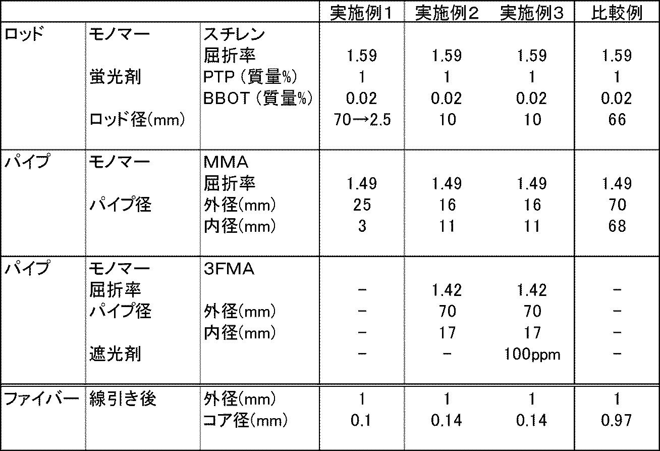
シンチレーション光の発光頻度は放射線がコアを通過する確率に比例する。すなわち、コア径の比に比例して発光頻度が変化する。
実施例1に係るシンチレーションファイバーは、比較例に対してシンチレーション光の発生頻度が0.1/0.97と少ない。また、外径は同じであるため、同等の強度とハンドリング性を有している。
実施例2に係るシンチレーションファイバーは、比較例に対してシンチレーション光の発生頻度が0.14/0.97と少ない。また、外径は同じであるため、同等の強度とハンドリング性を有している。
実施例3に係るシンチレーションファイバーは、比較例に対してコアでのシンチレーション光の発生頻度が0.14/0.97と少ない。また、外径は同じであるため、同等の強度とハンドリング性を有している。さらに、アウタークラッドが遮光剤を含有しているため、アウタークラッドで発生するシンチレーション光によるノイズが低減する。
実施例1に係るシンチレーションファイバーは、比較例に対してシンチレーション光の発生頻度が0.1/0.97と少ない。また、外径は同じであるため、同等の強度とハンドリング性を有している。
実施例2に係るシンチレーションファイバーは、比較例に対してシンチレーション光の発生頻度が0.14/0.97と少ない。また、外径は同じであるため、同等の強度とハンドリング性を有している。
実施例3に係るシンチレーションファイバーは、比較例に対してコアでのシンチレーション光の発生頻度が0.14/0.97と少ない。また、外径は同じであるため、同等の強度とハンドリング性を有している。さらに、アウタークラッドが遮光剤を含有しているため、アウタークラッドで発生するシンチレーション光によるノイズが低減する。
本発明は上記実施の形態に限られず、趣旨を逸脱しない範囲で適宜変更可能である。
この出願は、2016年8月30日に出願された日本出願特願2016-167732を基礎とする優先権を主張し、その開示の全てをここに取り込む。
1 コア
2 クラッド
21 インナークラッド
22 アウタークラッド
2 クラッド
21 インナークラッド
22 アウタークラッド
Claims (6)
- 紫外線発光性を有する蛍光剤を含有するコアと、前記コアの外周面を被覆すると共に、前記コアよりも低い屈折率を有するクラッドと、を有するプラスチックシンチレーションファイバーであって、
前記クラッドの外径が0.5~2.0mmであり、前記コアの径が0.2mm以下である、プラスチックシンチレーションファイバー。 - 前記クラッドが、インナークラッドと、前記インナークラッドの外周面を被覆すると共に、前記インナークラッドよりも低い屈折率を有するアウタークラッドとを含むマルチクラッド構造を有している、請求項1に記載のプラスチックシンチレーションファイバー。
- 前記アウタークラッドが、遮光剤を含有する、請求項2に記載のプラスチックシンチレーションファイバー。
- 紫外線発光性を有する蛍光剤を含有するコアと、前記コアの外周面を被覆するクラッドと、を備えたプラスチックシンチレーションファイバーの製造方法であって、
紫外線発光性を有する蛍光剤を含有する樹脂からなる棒状のコア用ロッドを、前記コア用ロッドよりも低い屈折率を有する樹脂からなる円筒状のクラッド用パイプに挿入してプリフォームを作製する工程と、
前記プリフォームを加熱しつつ線引きする工程と、を備え、
線引きする工程において、前記クラッドの外径を0.5~2.0mmとし、前記コアの径を0.2mm以下とする、プラスチックシンチレーションファイバーの製造方法。 - 前記クラッド用パイプを、インナークラッド用パイプと、前記インナークラッド用パイプの外周面を被覆すると共に、前記インナークラッド用パイプよりも低い屈折率を有する樹脂からなるアウタークラッド用パイプとから構成する、請求項4に記載のプラスチックシンチレーションファイバーの製造方法。
- 前記アウタークラッド用パイプを、遮光剤を含有する樹脂から構成する、請求項5に記載のプラスチックシンチレーションファイバーの製造方法。
Priority Applications (1)
| Application Number | Priority Date | Filing Date | Title |
|---|---|---|---|
| JP2018537248A JP6902549B2 (ja) | 2016-08-30 | 2017-08-28 | 高線量場プラスチックシンチレーションファイバー及びその製造方法 |
Applications Claiming Priority (2)
| Application Number | Priority Date | Filing Date | Title |
|---|---|---|---|
| JP2016167732 | 2016-08-30 | ||
| JP2016-167732 | 2016-08-30 |
Publications (1)
| Publication Number | Publication Date |
|---|---|
| WO2018043383A1 true WO2018043383A1 (ja) | 2018-03-08 |
Family
ID=61301200
Family Applications (1)
| Application Number | Title | Priority Date | Filing Date |
|---|---|---|---|
| PCT/JP2017/030698 Ceased WO2018043383A1 (ja) | 2016-08-30 | 2017-08-28 | 高線量場プラスチックシンチレーションファイバー及びその製造方法 |
Country Status (2)
| Country | Link |
|---|---|
| JP (1) | JP6902549B2 (ja) |
| WO (1) | WO2018043383A1 (ja) |
Cited By (4)
| Publication number | Priority date | Publication date | Assignee | Title |
|---|---|---|---|---|
| WO2020145278A1 (ja) | 2019-01-10 | 2020-07-16 | 株式会社クラレ | 低透過性放射線検出プラスチックシンチレーションファイバ |
| WO2021020478A1 (ja) * | 2019-07-30 | 2021-02-04 | 株式会社クラレ | プラスチック波長変換ファイバ |
| WO2022154071A1 (ja) * | 2021-01-15 | 2022-07-21 | 株式会社クラレ | プラスチック波長変換ファイバ及びその製造方法 |
| JP2022542383A (ja) * | 2019-07-29 | 2022-10-03 | サン-ゴバン セラミックス アンド プラスティクス,インコーポレイティド | プラスチック波長シフトファイバおよびその作製方法 |
Families Citing this family (1)
| Publication number | Priority date | Publication date | Assignee | Title |
|---|---|---|---|---|
| CN113126138B (zh) * | 2021-04-23 | 2022-11-11 | 重庆大学 | 一种多层耦合结构高分辨闪烁屏制造方法及其闪烁屏 |
Citations (4)
| Publication number | Priority date | Publication date | Assignee | Title |
|---|---|---|---|---|
| JP2000137122A (ja) * | 1998-10-30 | 2000-05-16 | Nissei Denki Kk | プラスチックシンチレーションファイバ |
| JP2007212947A (ja) * | 2006-02-13 | 2007-08-23 | Mitsubishi Cable Ind Ltd | ダブルクラッドファイバの製造方法及びダブルクラッドファイバ |
| US20100127177A1 (en) * | 2008-11-24 | 2010-05-27 | Schmitt William M | Discrimination-enhanced fiber-optic scintillator radiation detector |
| WO2013179970A1 (ja) * | 2012-05-31 | 2013-12-05 | 株式会社クラレ | ケーブル、及び放射線測定装置 |
Family Cites Families (4)
| Publication number | Priority date | Publication date | Assignee | Title |
|---|---|---|---|---|
| US5420959A (en) * | 1992-12-17 | 1995-05-30 | Nanoptics Incorporated | High efficiency, high resolution, real-time radiographic imaging system |
| JP4323704B2 (ja) * | 2000-08-24 | 2009-09-02 | 日立電線株式会社 | ワイヤ放電加工用電極線 |
| JP5033719B2 (ja) * | 2008-06-20 | 2012-09-26 | 株式会社フジクラ | 光ファイバ母材の製造方法 |
| US8031989B2 (en) * | 2008-09-17 | 2011-10-04 | Honeywell International Inc. | Radiological and nuclear optical sensor |
-
2017
- 2017-08-28 JP JP2018537248A patent/JP6902549B2/ja active Active
- 2017-08-28 WO PCT/JP2017/030698 patent/WO2018043383A1/ja not_active Ceased
Patent Citations (4)
| Publication number | Priority date | Publication date | Assignee | Title |
|---|---|---|---|---|
| JP2000137122A (ja) * | 1998-10-30 | 2000-05-16 | Nissei Denki Kk | プラスチックシンチレーションファイバ |
| JP2007212947A (ja) * | 2006-02-13 | 2007-08-23 | Mitsubishi Cable Ind Ltd | ダブルクラッドファイバの製造方法及びダブルクラッドファイバ |
| US20100127177A1 (en) * | 2008-11-24 | 2010-05-27 | Schmitt William M | Discrimination-enhanced fiber-optic scintillator radiation detector |
| WO2013179970A1 (ja) * | 2012-05-31 | 2013-12-05 | 株式会社クラレ | ケーブル、及び放射線測定装置 |
Non-Patent Citations (2)
| Title |
|---|
| IKHLEF,A ET AL.: "X-ray imaging and detection using plastic scintillating fibers", NUCLEAR INSTRUMENTS AND METHODS IN PHYSICS RESEARCH SECTIONA, vol. 422, no. 1-3, 11 March 2000 (2000-03-11), pages 428 - 432, XP004193531, DOI: doi:10.1016/S0168-9002(99)01268-1 * |
| NISHIMURA ET AL: "Plasma Diagnostics High Resolution X −Ray magihg and Neutron. Diagnostics for Laser Fusion Experiments", THE JAPAN SOCIETY OF PLASMA SCIENCE AND NUCLEAR FUSION RESEARCH, vol. 70, no. 12, December 1994 (1994-12-01), pages 1259 - 1268, XP055603154 * |
Cited By (20)
| Publication number | Priority date | Publication date | Assignee | Title |
|---|---|---|---|---|
| JPWO2020145278A1 (ja) * | 2019-01-10 | 2021-11-18 | 株式会社クラレ | 低透過性放射線検出プラスチックシンチレーションファイバ |
| WO2020145278A1 (ja) | 2019-01-10 | 2020-07-16 | 株式会社クラレ | 低透過性放射線検出プラスチックシンチレーションファイバ |
| JP7394073B2 (ja) | 2019-01-10 | 2023-12-07 | 株式会社クラレ | 低透過性放射線検出プラスチックシンチレーションファイバ |
| US11402571B2 (en) | 2019-01-10 | 2022-08-02 | Kuraray Co., Ltd. | Weakly-penetrating radiation detection plastic scintillating fiber |
| EP3910378A4 (en) * | 2019-01-10 | 2022-08-03 | Kuraray Co., Ltd. | PLASTIC SCINTILLATION FIBER FOR DETECTING LOW-PENETRATING RADIATION |
| EP4004616A4 (en) * | 2019-07-29 | 2023-07-26 | Saint-Gobain Ceramics & Plastics Inc. | Plastic wavelength shifting fiber and a method of making the same |
| JP7731961B2 (ja) | 2019-07-29 | 2025-09-01 | サン-ゴバン セラミックス アンド プラスティクス,インコーポレイティド | プラスチック波長シフトファイバおよびその作製方法 |
| US12061357B2 (en) | 2019-07-29 | 2024-08-13 | Luxium Solutions, Llc | Plastic wavelength shifting fiber and a method of making the same |
| JP2024037906A (ja) * | 2019-07-29 | 2024-03-19 | サン-ゴバン セラミックス アンド プラスティクス,インコーポレイティド | プラスチック波長シフトファイバおよびその作製方法 |
| JP2022542383A (ja) * | 2019-07-29 | 2022-10-03 | サン-ゴバン セラミックス アンド プラスティクス,インコーポレイティド | プラスチック波長シフトファイバおよびその作製方法 |
| CN114144636B (zh) * | 2019-07-30 | 2024-04-16 | 株式会社可乐丽 | 塑料波长位移光纤 |
| JP7428714B2 (ja) | 2019-07-30 | 2024-02-06 | 株式会社クラレ | プラスチック波長変換ファイバ |
| CN114144636A (zh) * | 2019-07-30 | 2022-03-04 | 株式会社可乐丽 | 塑料波长位移光纤 |
| JPWO2021020478A1 (ja) * | 2019-07-30 | 2021-02-04 | ||
| WO2021020478A1 (ja) * | 2019-07-30 | 2021-02-04 | 株式会社クラレ | プラスチック波長変換ファイバ |
| CN116685658A (zh) * | 2021-01-15 | 2023-09-01 | 株式会社可乐丽 | 塑料波长位移光纤及其制造方法 |
| JPWO2022154071A1 (ja) * | 2021-01-15 | 2022-07-21 | ||
| WO2022154071A1 (ja) * | 2021-01-15 | 2022-07-21 | 株式会社クラレ | プラスチック波長変換ファイバ及びその製造方法 |
| EP4279564A4 (en) * | 2021-01-15 | 2024-11-06 | Kuraray Co., Ltd. | PLASTIC WAVELENGTH CONVERSION FIBER AND MANUFACTURING METHOD THEREOF |
| JP7808060B2 (ja) | 2021-01-15 | 2026-01-28 | 株式会社クラレ | プラスチック波長変換ファイバ及びその製造方法 |
Also Published As
| Publication number | Publication date |
|---|---|
| JPWO2018043383A1 (ja) | 2019-06-24 |
| JP6902549B2 (ja) | 2021-07-14 |
Similar Documents
| Publication | Publication Date | Title |
|---|---|---|
| EP3557288B1 (en) | Method of producing a plastic scintillation fiber | |
| JP7048349B2 (ja) | 高線量場プラスチックシンチレーションファイバー及びその製造方法 | |
| JP6902549B2 (ja) | 高線量場プラスチックシンチレーションファイバー及びその製造方法 | |
| CN116324519B (zh) | 塑料闪烁光纤及其制造方法 | |
| JP6963547B2 (ja) | プラスチックシンチレーションファイバ及びその製造方法 | |
| JP2018200172A (ja) | プラスチック波長変換ファイバ及びその製造方法 | |
| JP7645899B2 (ja) | プラスチックシンチレーションファイバ及びその製造方法 | |
| US11402571B2 (en) | Weakly-penetrating radiation detection plastic scintillating fiber | |
| JP7645894B2 (ja) | プラスチックシンチレーションファイバ及びその製造方法 | |
| EP4279564B1 (en) | Plastic wavelength shifting fiber and its manufacturing method | |
| EP4053856A1 (en) | Plastic scintillating fiber and production method therefor | |
| EP4006124B1 (en) | Plastic wavelength conversion fiber |
Legal Events
| Date | Code | Title | Description |
|---|---|---|---|
| WWE | Wipo information: entry into national phase |
Ref document number: 2018537248 Country of ref document: JP |
|
| 121 | Ep: the epo has been informed by wipo that ep was designated in this application |
Ref document number: 17846388 Country of ref document: EP Kind code of ref document: A1 |
|
| NENP | Non-entry into the national phase |
Ref country code: DE |
|
| 122 | Ep: pct application non-entry in european phase |
Ref document number: 17846388 Country of ref document: EP Kind code of ref document: A1 |