WO2018043194A1 - 屈折率測定装置及び屈折率測定方法 - Google Patents
屈折率測定装置及び屈折率測定方法 Download PDFInfo
- Publication number
- WO2018043194A1 WO2018043194A1 PCT/JP2017/029871 JP2017029871W WO2018043194A1 WO 2018043194 A1 WO2018043194 A1 WO 2018043194A1 JP 2017029871 W JP2017029871 W JP 2017029871W WO 2018043194 A1 WO2018043194 A1 WO 2018043194A1
- Authority
- WO
- WIPO (PCT)
- Prior art keywords
- light
- refractive index
- polarized light
- thin film
- sample
- Prior art date
- Legal status (The legal status is an assumption and is not a legal conclusion. Google has not performed a legal analysis and makes no representation as to the accuracy of the status listed.)
- Ceased
Links
Images














Classifications
-
- G—PHYSICS
- G01—MEASURING; TESTING
- G01N—INVESTIGATING OR ANALYSING MATERIALS BY DETERMINING THEIR CHEMICAL OR PHYSICAL PROPERTIES
- G01N21/00—Investigating or analysing materials by the use of optical means, i.e. using sub-millimetre waves, infrared, visible or ultraviolet light
- G01N21/17—Systems in which incident light is modified in accordance with the properties of the material investigated
- G01N21/41—Refractivity; Phase-affecting properties, e.g. optical path length
Definitions
- the present invention relates to a refractive index measuring apparatus and a refractive index measuring method.
- the surface plasmon resonance (SPR) phenomenon is a phenomenon in which light interacts with free electrons existing on the metal surface, and a part of the light is absorbed according to the refractive index of the medium in contact with the metal.
- SPR surface plasmon resonance
- a metal thin film with a thickness of several tens of nanometers is formed on the side surface of a quartz glass rod (optical fiber core), and the intensity of light incident from one end of the optical fiber and emitted from the other end is measured.
- the refractive index of the sample in contact with the metal thin film is measured (see, for example, Patent Documents 1 to 4).
- the incident light is incident on and emitted from the core of the optical fiber without observing the change in the reflection intensity by changing the incident angle using the driving mechanism.
- the refractive index of the sample can be measured simply by measuring the intensity.
- an optical fiber type measuring device that measures the refractive index by entering light into the core of an optical fiber on which a metal thin film is formed, the light is refracted by fluctuations in light intensity at the light source or light leakage from the side of the optical fiber. There is concern about a decrease in the accuracy of rate measurement.
- the range of refractive index that can be measured is limited depending on the type of metal used as the metal thin film and the wavelength of light.
- the present invention has been made in view of the above circumstances, and can improve the measurement accuracy of the refractive index of the sample and expand the measurement range, and can also detect the position information of the sample and the like. And it aims at providing a refractive index measuring method.
- a refractive index measuring apparatus comprises: A light projecting unit that emits light including a plurality of linearly polarized light components having different polarization directions; After the light from the light projecting portion is incident from one end, totally reflected by the side surface formed in part with the metal thin film that generates the surface plasmon resonance phenomenon, the elongated columnar waveguide portion that exits from the other end, and A polarizing filter unit that extracts a linearly polarized light component in a specific direction in the light emitted from the waveguide unit; A selection unit that selects a polarization direction of a linearly polarized component of the light extracted by the polarization filter unit; A light intensity detection unit for detecting the intensity of the linearly polarized light component of the light extracted by the polarization filter unit; Based on the light intensity detected by the light intensity detection unit, a measurement unit for measuring the refractive index of the sample, With In the waveguide section, Any of the plurality
- the waveguide section is The plurality of side surfaces include a first side surface on which a metal thin film is formed and a second side surface on which no metal thin film is formed,
- the measuring unit is When the P-polarized light corresponding to the first side surface is selected by the selection unit, the first light intensity detected by the light intensity detection unit and the P-polarization corresponding to the second side surface are selected by the selection unit. Measuring the refractive index of the sample based on the second light intensity detected by the light intensity detector when selected, It is good as well.
- the metal thin film formed on each of the plurality of side surfaces of the waveguide portion is The metal type or film thickness differs for each side,
- the measuring unit is Based on the measurement result of the light intensity of P-polarized light corresponding to each of the plurality of side surfaces, the refractive index of the sample is measured. It is good as well.
- the measuring unit is Based on the measurement result of the light intensity of P-polarized light corresponding to each of the plurality of side surfaces, the refractive index of the sample is measured, and the position information of the sample is detected. It is good as well.
- the measuring unit is Based on the measurement result of the light intensity of P-polarized light corresponding to each of the plurality of side surfaces, the refractive index of the sample is measured, and the position information of the sample is detected. It is good as well.
- the refractive index measurement method includes: From one end of the waveguide member provided with a plurality of planar side surfaces each having a long columnar shape and any one of a plurality of linearly polarized light components included in incident light being P-polarized light and having different responses to P-polarized light.
- Incident light from a light projecting portion including a plurality of linearly polarized light components different from each other, totally reflected by the plurality of side surfaces, and then emitted from the other end of the waveguide member, While selectively extracting the linearly polarized light component in a specific direction in the light emitted from the waveguide section, the intensity of the linearly polarized light component of the selectively extracted light is detected, Based on the detected light intensity, the refractive index of the sample is measured.
- the present invention it is possible to selectively obtain a plurality of measurement results based on light reflected from different side surfaces, each of which is associated with the occurrence of the surface plasmon resonance phenomenon, with only one waveguide section.
- Multiple measurement results should include only disturbance components depending on the state of the side surface, include those with different measurable refractive index ranges, or include information that can detect the position information of the sample, etc. Can do. Therefore, by combining the measurement results on each of the plurality of side surfaces, the measurement accuracy of the refractive index of the sample can be improved and the measurement range can be expanded, and the position information of the sample and the like can be detected.
- FIG. 1 It is a schematic diagram which shows the whole structure of the refractive index measuring apparatus which concerns on Embodiment 1 of this invention. It is a perspective view of a waveguide member. It is a flowchart which shows the flow of operation
- FIG. 1 shows four states measurable with a refractive index measuring apparatus.
- FIG. 2 which shows four states measurable with a refractive index measuring apparatus.
- FIG. 3 which shows four states measurable with a refractive index measuring apparatus.
- FIG. (4) which shows four states measurable with a refractive index measuring apparatus.
- FIG. 4 It is a perspective view which shows the structure of the waveguide part of the refractive index measuring apparatus which concerns on Embodiment 4 of this invention. It is a figure (the 1) which shows four states measurable with a refractive index measuring apparatus. It is a figure (the 2) which shows four states measurable with a refractive index measuring apparatus. It is FIG. (The 3) which shows four states measurable with a refractive index measuring apparatus. It is FIG. (4) which shows four states measurable with a refractive index measuring apparatus.
- 7 is a graph showing a change in response when an aqueous ethanol solution having a concentration of 0 to 30% is caused to flow through a pipeline in the refractive index measurement apparatus according to Embodiment 3 of the present invention. It is a graph which shows the change of a response when the density
- Embodiment 1 FIG. First, the first embodiment of the present invention will be described.
- the refractive index measuring apparatus 1 includes a power source 2, a light emitting diode (LED) 3 as a light projecting unit, a waveguide member 4, and a lens 5. , A polarizing plate 6 serving as a polarizing filter unit, a selecting unit 7, a light receiving unit 8 serving as a light intensity detecting unit, a light receiving circuit 9, and a measuring unit 10.
- the power source 2 is a DC stabilized power source that supplies current to the LED 3.
- the LED 3 emits light by the current supplied from the power source 2. This light is light in a wavelength band that can generate a surface plasmon resonance phenomenon, and includes linearly polarized light components having different polarization directions.
- the waveguide member 4 is a columnar light guide member elongated in the direction of the optical axis AX (y-axis direction).
- the LED 3 is disposed on the optical axis AX of the waveguide member 4.
- the waveguide member 4 receives light from the LED 3 from one end (the end on the ⁇ y side).
- the incident light travels in the waveguide member 4 in the + y direction while being totally reflected by the side surface partially formed with the metal thin film 4B that generates the surface plasmon resonance phenomenon.
- the waveguide member 4 emits light from the other end on the + y side.
- the lens 5 is a refractive optical system and is disposed on the optical axis AX of the waveguide member 4.
- the lens 5 collects the light emitted from the waveguide member 4 and makes it incident on the polarizing plate 6.
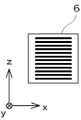
- the polarizing plate 6 is disposed on the optical axis AX of the waveguide member 4 and extracts a linearly polarized light component in a specific direction in the light emitted from the waveguide member 4.
- the selection unit 7 selects the polarization direction of the linearly polarized light component of the light extracted by the polarizing plate 6 by rotationally driving the polarizing plate 6 about the optical axis AX using a driving mechanism.
- the selection unit 7 may be manually operated or may be automatically operated.
- the light receiving unit 8 is disposed on the optical axis AX of the waveguide member 4.
- the light receiving unit 8 receives the light that has passed through the polarizing plate 6 and detects the light intensity of the linearly polarized light component of the light extracted by the polarizing plate 6.
- the light receiving unit 8 generates a current corresponding to the light intensity.
- the current generated in the light receiving unit 8 is converted into a voltage by the light receiving circuit 9 including the capacitor 9A and the resistor 9B and input to the measuring unit 10.
- the pipeline 11 is disposed around the waveguide member 4.
- a liquid (solvent) containing the sample 12 flows through the pipeline 11.
- the refractive index measuring device 1 measures the refractive index of the sample 12 contained in this liquid.
- the measurement unit 10 measures the refractive index of the sample 12 in contact with the metal thin film 4 ⁇ / b> B based on the voltage value corresponding to the light intensity detected by the light receiving unit 8.
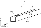
- the waveguide member 4 will be described in more detail. As shown in FIG. 2, the waveguide member 4 is configured around an elongated rectangular columnar glass rod 4 ⁇ / b> A extending in the direction of the optical axis AX (y-axis direction). Although the refractive index of the glass rod 4A is desirably high, it is 1.458, for example.
- the side surface on the + z side of the glass rod 4A is the side surface 4Aa (first side surface), and the side surface on the + x side is the side surface 4Ab (second side surface).
- a metal thin film 4B is formed on the side surface 4Aa by using a vacuum deposition method or the like.
- the metal thin film 4B is formed on the side surface 4Aa, and the metal thin film 4B is not formed on the side surface 4Ab. That is, the waveguide member 4 is formed so that the generation state of the surface plasmon resonance phenomenon is different in the circumferential direction.
- the waveguide member 4 is provided with a plurality of planar side surfaces 4Aa and 4Ab each having one of a plurality of linearly polarized light components included in the incident light being P-polarized light and having different responses to the P-polarized light. .
- the refractive index measuring device 1 causes light from the LED 3 including a plurality of linearly polarized components having different polarization directions to enter one end of the waveguide member 4 to generate a surface plasmon resonance phenomenon. After the total reflection at the side surface on which the metal thin film 4B is formed in part, the metal thin film 4B is emitted from the other end of the waveguide member 4 (step S1). Subsequently, the refractive index measuring apparatus 1 drives the polarizing plate 6 by the selection unit 7 to selectively extract a linearly polarized light component in a specific direction in the light emitted from the waveguide member 4, while polarizing the polarizing plate 6. The intensity of the linearly polarized light component extracted in step S2 is detected (step S2). Furthermore, the refractive index measuring device 1 measures the refractive index of the sample 12 based on the light intensity detected by the light receiving unit 8 (step S3).
- the linearly polarized light component in step S2 will be described.
- the linearly polarized light component parallel to the light incident surface of the side surface 4Aa on which the metal thin film 4B is formed becomes P-polarized light with respect to the side surface 4Aa.
- FIG. 4B when the P-polarized light is incident on the metal thin film 4B at a specific incident angle, surface plasmon resonance occurs, the intensity of the reflected light decreases, and finally the light is emitted from the other end of the waveguide member 4. The light intensity is reduced.
- the selection unit 7 may set the direction of the polarizing plate 6 to the z-axis direction as shown in FIG. 4C.
- the linearly polarized light component orthogonal to the incident surface of the side surface 4Aa on which the metal thin film 4B is formed becomes S-polarized light with respect to the side surface 4Aa.
- the surface plasmon resonance phenomenon does not occur and the intensity of the reflected light does not decrease. Therefore, the S-polarized light emitted from the other end of the waveguide member 4 is not lowered by the surface plasmon resonance phenomenon.
- the selection unit 7 may set the direction of the polarizing plate 6 to the x-axis direction as shown in FIG. 5C.
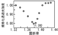
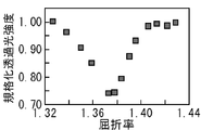
- FIG. 6A shows the relationship between the normalized transmitted light intensity of P-polarized light and the refractive index.
- the light intensity of P-polarized light has a large sensitivity with respect to the refractive index of the sample 12, and changes greatly.
- the response curve of the light intensity of P-polarized light (standardized transmitted light intensity) is a curve having a minimum value at a refractive index of about 1.380.
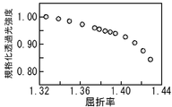
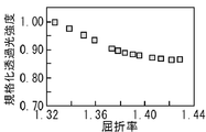
- FIG. 6B shows the relationship between the normalized transmitted light intensity of S-polarized light and the refractive index.
- the light intensity of S-polarized light gradually decreases as the refractive index of the sample 12 increases.
- the decrease in light intensity is caused by light leakage due to the difference in refractive index between the glass rod 4A and the sample 12, and as the refractive index of the sample 12 increases, light leakage from the side surface 4Ab of the glass rod 4A and the like. Indicates that it is growing. This leakage of light becomes one of the causes of a decrease in the detection accuracy of the refractive index of the sample 12.
- the measurement unit 10 uses the light intensity (see FIG. 6A) detected by the light receiving unit 8 when the selection unit 7 selects a linearly polarized light component (P-polarized light) parallel to the incident surface of the side surface 4Aa of the glass rod 4A. Based on the light intensity (see FIG. 6B) detected by the light receiving unit 8 when the selection unit 7 selects a linearly polarized light component (S-polarized light) orthogonal to the incident surface of the side surface 4Ab of the glass rod 4A, the sample 12 The refractive index of is measured.
- P-polarized light linearly polarized light component
- S-polarized light linearly polarized light component
- the measurement unit 10 divides the normalized transmitted light intensity of P-polarized light by the normalized transmitted light intensity of S-polarized light, and obtains the refractive index of the sample 12 based on the division result.
- FIG. 7 shows the refractive index characteristic of the normalized transmitted light intensity obtained by such division.
- the flat side surface 4Aa on which the metal thin film 4B is formed and the metal thin film 4B are not formed. And a side surface 4Ab.
- the measuring unit 10 measures the refractive index of the sample 12 by correcting the transmitted light intensity by dividing the S-polarized light intensity from the P-polarized light intensity of the side surface 4Aa on which the metal thin film 4B is formed. Thereby, the influence of light leakage from the side surface 4Ab and the like of the glass rod 4A and the influence of fluctuation of the light intensity emitted from the LED 3 can be reduced, and the refractive index of the sample 12 can be measured more accurately.
- a glass rod 4 ⁇ / b> A having a square cross section with a side of 5 mm can be used.
- the length of the glass rod 4A can be 150 mm
- the metal thin film 4B can be gold
- the length can be 100 mm.
- the thickness of the metal (gold) thin film 4B can be set to 45 nm, for example.
- the thickness of the metal (gold) thin film 4B is set to an appropriate thickness according to the type of metal.
- the LED 3 a red light emitting diode having an actually measured wavelength of 654 nm can be used.
- a methanol solution of ethylene glycol can be used as a solution to be passed through the pipeline 11.
- the sample 12 is a methanol solution of ethylene glycol. Since there is a correlation between the refractive index and the concentration of the ethylene glycol methanol solution, if the refractive index of the ethylene glycol methanol solution is known, the ethylene glycol concentration in the solution can be determined.
- Embodiment 2 FIG. Next, a second embodiment of the present invention will be described.
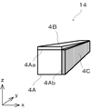
- the configuration of the refractive index measuring apparatus 1 is different from that of the first embodiment in that a waveguide member 14 is provided instead of the waveguide member 4 as shown in FIG. Specifically, in the waveguide member 14, a metal thin film is formed on each of the plurality of side surfaces 4Aa and 4Ab. Further, the metal thin film formed on the side surface 4Aa is different from the metal thin film formed on the side surface 4Ab.
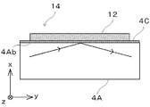
- the metal (gold) thin film 4B is formed on the side surface 4Aa of the glass rod 4A, and the metal (aluminum) thin film 4C is formed on the side surface 4Ab of the glass rod.
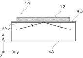
- the linearly polarized light component parallel to the light incident surface of the side surface 4Aa on which the metal (gold) thin film 4B is formed is P with respect to the side surface 4Aa. It becomes polarized light.
- FIG. 9B when the P-polarized light is incident on the metal (gold) thin film 4B at a specific incident angle, surface plasmon resonance occurs, and the intensity of reflected light decreases.
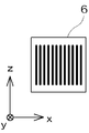
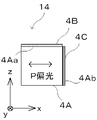
- the selection unit 7 may set the direction of the polarizing plate 6 to the z-axis direction as shown in FIG. 9C.
- the linearly polarized light component parallel to the light incident surface of the side surface 4Ab on which the metal (aluminum) thin film 4C is formed is P-polarized light.
- the selection unit 7 may set the direction of the polarizing plate 6 to the x-axis direction.
- FIG. 11A shows the relationship between the P-polarized normalized transmitted light intensity and the refractive index for the metal (gold) thin film 4B.
- the light intensity of P-polarized light with respect to the metal (gold) thin film 4B varies greatly depending on the refractive index of the sample 12.
- FIG. 11B shows the relationship between the P-polarized normalized transmitted light intensity and the refractive index for the metal (aluminum) thin film 4C.
- the light intensity of the P-polarized light with respect to the metal (aluminum) thin film 4C gradually decreases as the refractive index of the sample 12 increases, and there is no portion where it extremely decreases.
- the P-polarized light with respect to the metal (gold) thin film 4B has high sensitivity to the refractive index in a narrow range.
- the sensitivity to the refractive index of the sample 12 is lower than that of the metal (gold) thin film 4B, the light intensity changes in a wide range of the refractive index. Yes.
- the measurement unit 10 narrows the range of the refractive index of the sample 12 based on the measurement result of the P-polarized light intensity with respect to the metal (aluminum) thin film 4C, and further, the P-polarized light intensity with respect to the metal (gold) thin film 4B. Based on the measurement result, the refractive index of the sample 12 is measured in detail. In this way, the refractive index of the sample 12 can be measured more accurately in a wide measurement range.
- the metal type (gold / aluminum) is different between the metal thin film 4B formed on the side surface 4Aa and the metal thin film 4C formed on the side surface 4Ab.
- the metal thin film formed on the side surface 4Aa and the metal thin film formed on the side surface 4Ab may be made of the same type of metal and may have different film thicknesses.
- a silver thin film layer (metal thin film provided in place of the metal (gold) thin film 4B) having a thickness of 30 nm and a length of 10 cm is formed on the side surface 4Aa of the 2 mm square glass rod 4A.
- a silver thin film layer (metal thin film provided in place of the metal (aluminum) thin film 4C) having a thickness of 70 nm and a length of 10 cm was formed on the side surface 4Ab. Then, polarized light was selected by the polarizing plate 6 installed in front of the light receiving portion (photodiode) 8, and a response surface was selected.
- Embodiment 3 FIG. Next, a third embodiment of the present invention will be described.
- the configuration of the refractive index measuring apparatus 1 is different from that of the first embodiment in that a waveguide member 24 is provided instead of the waveguide member 4.
- the waveguide member 24 has a plurality of side surfaces, like the waveguide member 4.
- the waveguide member 24 has a different position in the longitudinal direction where the metal thin film is formed for each side surface.
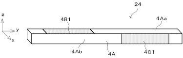
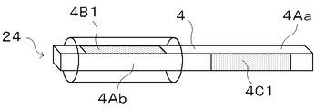
- a metal thin film 4B1 is formed at a portion on the ⁇ y side of the longitudinal center of the side surface 4Aa of the glass rod 4A, and the longitudinal center of the side surface 4Ab of the glass rod 4A is formed.
- a metal thin film 4C1 is formed on the + y side. That is, in the waveguide member 24, the metal thin films 4B1 and 4C1 are formed by vacuum deposition while shifting their positions on two adjacent side surfaces.
- the measurement unit 10 measures the P-polarized light intensity for the metal thin film 4B1 and the P-polarized light intensity for the metal thin film 4C1. If it does in this way, in addition to the refractive index of the sample 12, the positional information on the sample 12 can be measured with the combination of each measurement result.
- the waveguide member 24 is assumed to be filled with a solution (solvent) containing the sample 12.
- a solution solvent
- FIG. 13A a state in which there is no sample 12 on the metal thin films 4B1 and 4C1 and only the solvent exists is referred to as a state A.
- a state in which the sample 12 is present on the metal thin film 4B1 and only the solvent is present on the metal thin film 4C1 is referred to as a state B.
- a state in which only the solvent exists on the metal thin film 4B1 and the sample 12 exists on the metal thin film 4C1 is referred to as a state C.
- a state in which the sample 12 exists on the metal thin films 4B1 and 4C1 and covers the waveguide member 24 is referred to as a state D.
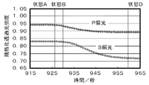
- FIG. 14 shows the response of the P-polarized light intensity to the metal thin film 4B1 in the states A to D and the response of the P-polarized light intensity to the metal thin film 4C1.
- the state A neither the metal thin film 4B1 nor the metal thin film 4C1 has a response (reduction in light intensity).
- state B a response appears for the metal thin film 4B1, and there is no response for the metal thin film 4C1.
- state C there is no response in the metal thin film 4B1, and a response appears in the metal thin film 4C1.
- a response appears in both the metal thin film 4B1 and the metal thin film 4C1.
- the measurement unit 10 determines which of the states A to D is based on the response measurement of the P-polarized light intensity to the metal thin film 4B1 and the response of the P-polarized light intensity to the metal thin film 4C1. In addition to the refractive index of the sample 12, the position information of the sample 12 can also be detected.
- metal (gold) thin films 4B1 and 4C1 having a length of 3 cm and a thickness of 45 nm were formed on the side surfaces 4Aa and 4Ab of the 2 mm square glass rod 4A fixed in the pipeline 11.
- the distance between the metal (gold) thin film 4B1 and the metal (gold) thin film 4C1 was 3 cm.
- a polarizing plate 6 installed in front of the light receiving unit 8 is used to select polarized light, and a 0 to 30% aqueous ethanol solution is used as a sample 12 from the metal (gold) thin film 4B1 side to the pipeline 11. The change in response when flowing through was measured.
- FIG. 18 shows this change in response.
- FIG. 18 shows a light reception result of P-polarized light (P-polarized light with respect to the metal (gold) thin film 4B1) and a light reception result of S-polarized light (P-polarized light with respect to the metal (gold) thin film 4C1).
- P-polarized light P-polarized light with respect to the metal (gold) thin film 4B1
- S-polarized light P-polarized light with respect to the metal (gold) thin film 4C1
- the normalized transmitted light intensity decreases as the concentration of the ethanol aqueous solution increases in both P-polarized light and S-polarized light.
- FIG. 19 shows an enlarged response change at time T (see FIG. 18) when the concentration of the ethanol solution is changed from 20% to 30%.
- T time
- FIG. 19 shows that while the ethanol concentration changes from 20% to 30%, the state A (FIG. 13A, FIG. 14) transitions to the state B (FIG. 13B, FIG. 14), and the state D ( FIG. 13D and FIG. 14) show the transition.
- the metal of the metal thin film formed on the two side surfaces 4Aa and 4Ab is the same type (gold).
- the present invention is not limited to this, and a different metal is used for each side surface. Also good. Moreover, you may make it change the film thickness and length of a metal thin film for every side.
- Embodiment 4 FIG. Next, a fourth embodiment of the present invention will be described.
- the configuration of the refractive index measuring apparatus 1 is different from that of the first embodiment in that a waveguide member 34 is provided instead of the waveguide member 4. Specifically, in the waveguide member 34, a plurality of metal thin films having different areas are formed along the longitudinal direction.
- the amount of change in the response of the refractive index measuring device 1 to the sample 12 having the same refractive index is considered to be proportional to the area of the deposited metal. Therefore, in the present embodiment, as shown in FIG. 15, a plurality of metal thin films 4B1, 4B2, 4B3 are provided in the longitudinal direction of the side surface 4Aa of the glass rod 4A, and the vapor deposition area of the metal thin films 4B1, 4B2, 4B3 is The position information of the sample 12 is detected by making a difference such as 1: 2: 4 (the area ratio is a multiplier of 2) and taking the ratio of the change amount of the response (light intensity) in the measurement unit 10.
- the metal thin films 4C1, 4C2, and 4C3 are also provided in the longitudinal direction of the side surface 4Ab of the glass rod 4A.
- the metal thin films 4C1, 4C2, and 4C3 have the same area and are formed by vapor deposition.
- the area ratio between the metal thin film 4B1 and the metal thin film 4C1 is 4: 2
- the area ratio between the metal thin film 4B2 and the metal thin film 4C2 is 8:
- the area ratio between the metal thin film 4B3 and the metal thin film 4C3 is 16: 2. 2.
- a state in which the sample 12 exists only around the metal thin films 4B1 and 4C1 is referred to as a state A.
- a state in which the sample 12 exists around the metal thin films 4B1 and 4C1 and around the metal thin films 4B2 and 4C2 is referred to as a state B.
- a state where the sample 12 exists around the metal thin films 4B2 and 4C2 and around the metal thin films 4B3 and 4C3 is referred to as a state C.
- a state in which the sample 12 exists only around the metal thin films 4B3 and 4C3 is referred to as a state D.
- the ratio of the amount of change between the light intensity of the P-polarized light with respect to the side surface 4Aa and the light intensity of the P-polarized light with respect to the side surface 4Ab is uniquely determined by the position where the sample 12 exists. Therefore, the measurement unit 10 can detect the position information of the sample 12 based on the ratio of the amount of change between the P-polarized light intensity with respect to the side surface 4Aa and the P-polarized light intensity with respect to the side surface 4Ab.
- the measurement unit 10 can detect the refractive index of the sample 12 by dividing the amount of change in the P-polarized light intensity with respect to the side surface 4Aa or the amount of change in the P-polarized light intensity with respect to the side surface 4Ab by the area of the metal thin film. it can. Accordingly, the reaction of the solution in the pipeline 11 can be traced using the refractive index measuring device 1. In addition to monitoring the abnormal reaction (temperature change) in the reaction layer by utilizing the fact that the refractive index changes with temperature, the refractive index measuring device 1 can be used for various purposes.
- the area of the metal thin film is changed in the longitudinal direction, but the present invention is not limited to this.
- the type and thickness of the metal thin film may be changed in the longitudinal direction.
- Measurement results can be selectively obtained.
- the plurality of measurement results include only disturbance components, include those with different measurable refractive index ranges, and information that can detect the position information of the sample 12, etc. Can be included.
- the measurement accuracy of the refractive index of the sample 12 can be improved and the measurement range can be expanded, and the position information of the sample 12 and the like can be detected. it can.
- the present invention is not limited to this.
- a waveguide member in which the state of the side surface related to the occurrence of the surface plasmon resonance phenomenon is uniform and a metal thin film having a different response to P-polarized light is formed in the longitudinal direction of the waveguide member 4. You may make it employ
- the metal of the metal thin film is gold, silver or aluminum, but the present invention is not limited to this. Copper may be used as the metal of the metal thin film.
- a metal needs to be used appropriately according to the use.
- copper is easy to corrode and is easy to make copper sulfide, so it is not appropriate to use it in an environment where copper sulfide is easy to make.
- silver easily produces silver chloride, it is not appropriate to use it in an environment where silver chloride is easily produced.
- Aluminum forms thin alumina on the surface, but reacts with acid and alkali to corrode, so it is not appropriate to use it in an acidic or alkaline environment. Since gold is difficult to make a compound, it is optimal even when used in an environment where it reacts easily.
- the metal thin film may be a laminate of thin films made of different metals.
- a red light emitting diode is used as the LED 3.
- an LED that generates light having a shorter wavelength or longer wavelength may be used.
- the relationship between the metal thin film and the wavelength of light will be summarized. Such a relationship is an important factor in selecting the type of metal thin film and the wavelength of light.
- (1) In the case of gold-When a red or infrared light emitting diode is used, a good response can be obtained in a wide film thickness range. -The change in the minimum refractive index with wavelength is very large. This change becomes more pronounced as the film thickness increases. • Surface plasmon resonance is difficult to obtain with short-wavelength light.
- ⁇ Response is larger than gold. ⁇ Minimum change in refractive index with wavelength is small. -Response (surface plasmon resonance phenomenon) was also observed with the green LED.
- the light of the LED 3 may be light including a wide wavelength band from a long wavelength to a short wavelength. Since the refractive index with sensitivity differs depending on the type of metal, a thin film of different metal is formed on each of a plurality of side surfaces of the waveguide member 4 so that light of various wavelengths can be incident as in the present invention. For example, the range of the refractive index that can be measured can be greatly expanded.
- Polygonal glass rods are extremely easy to manufacture and can be disposable. For this reason, this invention is suitable not only for making it easy to improve a measurement precision or expanding a measurement range but for preventing contamination.
- a spacer made of a linear polymer may be provided on the metal thin film, and a fluororesin film may be formed thereon as a selective film.
- the fluororesin film has holes of molecular size and allows volatile substances to pass therethrough. For example, when the alcohol contained in sake or the like is used as the sample 12, the fluororesin film does not pass sugar or organic acid but passes only the alcohol component on the metal thin film. Therefore, the alcohol concentration can be accurately measured by providing the spacer and the fluororesin film.
- Sample 12 is generally a component contained in a solution (solvent).
- a solution for example, sake 12 and alcohol such as wine can be used as the sample 12.
- the gasoline contained in the engine oil can be used as the sample 12.
- a polarizing beam splitter may be disposed instead of the polarizing plate 6 so that the light divided by the polarizing beam splitter is received by the separate light receiving units 8 and the respective light intensities are detected. In this way, two light intensities with different side faces can be detected simultaneously. Further, a driving mechanism in the selection unit 7 such as rotating the polarizing plate 6 is also unnecessary.
- the cross section of the glass rod 4A is rectangular (square), but is not limited thereto.
- the cross-sectional shape of the glass rod 4A may be a rectangle, a rhombus, or a trapezoid.
- the cross-sectional shape of the glass rod 4A may be a triangle or a polygon that is a pentagon or more. It suffices if there are at least two plate-like side surfaces with different normal directions, and the other side surfaces may be curved surfaces.
- the measurement unit 10 calculates the mixed component at an angle formed by both side surfaces, subtracts the calculated mixed component from the measurement result of one light intensity, and calculates the subtracted value as the true light intensity. You can do it.
- the metal thin film may be formed on the side surface opposite to the side surface on which the metal thin film is formed.
- the present invention can be used for measuring the refractive index of a sample.
- the present invention can be applied to a frequency meter that measures the alcohol content in a shochu manufacturing process (distillation, aging, bottling, etc.).
- 1 Refractive index measuring device 2 power supply, 3 light emitting diode (LED), 4 waveguide member, 4A glass rod, 4Aa, 4Ab side, 4B, 4B1, 4B2, 4B3 metal (gold) thin film, 4C metal (aluminum) thin film, 4C1, 4C2, 4C3 metal (gold) thin film, 5 lens, 6 polarizing plate, 7 selection unit, 8 light receiving unit, 9 light receiving circuit, 9A capacitor, 9B resistance, 10 measuring unit, 11 pipeline, 12 sample (measurement target) , 14, 24, 34 Waveguide member
Landscapes
- Physics & Mathematics (AREA)
- Health & Medical Sciences (AREA)
- Life Sciences & Earth Sciences (AREA)
- Chemical & Material Sciences (AREA)
- Analytical Chemistry (AREA)
- Biochemistry (AREA)
- General Health & Medical Sciences (AREA)
- General Physics & Mathematics (AREA)
- Immunology (AREA)
- Pathology (AREA)
- Investigating Or Analysing Materials By Optical Means (AREA)
Abstract
LED(3)は偏光方向が異なる複数の直線偏光成分を含む光を出射する。細長柱状の導波路部材(4)はLED(3)からの光を一端から入射し、表面プラズモン共鳴現象を発生させる金属薄膜(4B)が一部に形成された側面(4Aa,4Ab)で全反射させた後、他端から出射する。偏光板(6)は導波路部材(4)から出射された光における特定の方向の直線偏光成分を抽出する。選択部(7)は偏光板(6)で抽出される光の直線偏光成分の偏光方向を選択する。受光部(8)は偏光板(6)で抽出された光の直線偏光成分の強度を検出する。測定部(10)は、受光部(8)で検出された光強度に基づいて、試料(12)の屈折率を測定する。導波路部材(4)には入射した光に含まれる複数の直線偏光成分のいずれかがP偏光となり、P偏光に対する応答がそれぞれ異なる平面状の複数の側面(4Aa,4Ab)が形成されている。
Description
本発明は、屈折率測定装置及び屈折率測定方法に関する。
表面プラズモン共鳴(SPR)現象とは、金属表面に存在する自由電子と光が相互作用を起こし、金属と接触している媒体の屈折率に応じて光の一部が吸収される現象である。このSPR現象を利用して、石英ガラス棒(光ファイバのコア)の側面に数十nmの厚さの金属薄膜を形成し、光ファイバの一端から入射し他端から出射した光の強度を測定することで、金属薄膜と接触している試料の屈折率を測定する(例えば、特許文献1乃至4参照)。
特許文献1乃至4に開示された屈折率測定装置によれば、駆動機構を用いて入射角度を変化させて反射強度の変化を観測することなく、光ファイバのコアに入射され出射された光の強度を測定するだけで、試料の屈折率を測定することができる。
しかしながら、金属薄膜が形成された光ファイバのコアに光を入射して屈折率を測定する光ファイバ型の測定装置では、光源における光強度の揺らぎや、光ファイバの側面からの光の漏れによる屈折率の測定精度の低下が懸念される。
また、このような屈折率測定装置では、一般に、金属薄膜として用いられる金属の種類や光の波長によって、測定可能な屈折率の範囲に制限がある。
さらに、試料が移動したり屈折率が変化する位置が変動したりするような場合には、屈折率を測定するのに加え、それらの位置情報を検出したいという要求もある。
本発明は、上記実情に鑑みてなされたものであり、試料の屈折率の測定精度を向上するとともに測定範囲を広げることができるうえ、試料等の位置情報を検出することができる屈折率測定装置及び屈折率測定方法を提供することを目的とする。
上記目的を達成するために、本発明の第1の観点に係る屈折率測定装置は、
偏光方向が異なる複数の直線偏光成分を含む光を出射する投光部と、
前記投光部からの光を一端から入射し、表面プラズモン共鳴現象を発生させる金属薄膜が一部に形成された側面で全反射させた後、他端から出射する細長柱状の導波路部と、
前記導波路部から出射された光における特定の方向の直線偏光成分を抽出する偏光フィルタ部と、
前記偏光フィルタ部で抽出される光の直線偏光成分の偏光方向を選択する選択部と、
前記偏光フィルタ部で抽出された光の直線偏光成分の強度を検出する光強度検出部と、
前記光強度検出部で検出された光強度に基づいて、試料の屈折率を測定する測定部と、
を備え、
前記導波路部には、
入射した光に含まれる複数の直線偏光成分のいずれかがP偏光となり、P偏光に対する応答がそれぞれ異なる平面状の複数の側面が形成されている。
偏光方向が異なる複数の直線偏光成分を含む光を出射する投光部と、
前記投光部からの光を一端から入射し、表面プラズモン共鳴現象を発生させる金属薄膜が一部に形成された側面で全反射させた後、他端から出射する細長柱状の導波路部と、
前記導波路部から出射された光における特定の方向の直線偏光成分を抽出する偏光フィルタ部と、
前記偏光フィルタ部で抽出される光の直線偏光成分の偏光方向を選択する選択部と、
前記偏光フィルタ部で抽出された光の直線偏光成分の強度を検出する光強度検出部と、
前記光強度検出部で検出された光強度に基づいて、試料の屈折率を測定する測定部と、
を備え、
前記導波路部には、
入射した光に含まれる複数の直線偏光成分のいずれかがP偏光となり、P偏光に対する応答がそれぞれ異なる平面状の複数の側面が形成されている。
この場合、前記導波路部は、
前記複数の側面として、金属薄膜が形成された第1の側面と、金属薄膜が形成されていない第2の側面を有しており、
前記測定部は、
前記第1の側面に対応するP偏光を前記選択部で選択したときに前記光強度検出部で検出された第1の光強度と、前記第2の側面に対応するP偏光を前記選択部で選択したときに前記光強度検出部で検出された第2の光強度とに基づいて、試料の屈折率を測定する、
こととしてもよい。
前記複数の側面として、金属薄膜が形成された第1の側面と、金属薄膜が形成されていない第2の側面を有しており、
前記測定部は、
前記第1の側面に対応するP偏光を前記選択部で選択したときに前記光強度検出部で検出された第1の光強度と、前記第2の側面に対応するP偏光を前記選択部で選択したときに前記光強度検出部で検出された第2の光強度とに基づいて、試料の屈折率を測定する、
こととしてもよい。
前記導波路部の前記複数の側面それぞれに形成された金属薄膜は、
側面毎に金属の種類又は膜厚が異なり、
前記測定部は、
複数の側面各々に対応するP偏光の光強度の測定結果に基づいて、試料の屈折率を測定する、
こととしてもよい。
側面毎に金属の種類又は膜厚が異なり、
前記測定部は、
複数の側面各々に対応するP偏光の光強度の測定結果に基づいて、試料の屈折率を測定する、
こととしてもよい。
前記導波路部では、
前記金属薄膜が形成された長手方向に関する位置が側面毎に異なり、
前記測定部は、
複数の側面各々に対応するP偏光の光強度の測定結果に基づいて、試料の屈折率を測定するとともに、試料の位置情報を検出する、
こととしてもよい。
前記金属薄膜が形成された長手方向に関する位置が側面毎に異なり、
前記測定部は、
複数の側面各々に対応するP偏光の光強度の測定結果に基づいて、試料の屈折率を測定するとともに、試料の位置情報を検出する、
こととしてもよい。
前記導波路部では、
面積がそれぞれ異なる複数の金属薄膜が、長手方向に沿って形成されており、
前記測定部は、
複数の側面各々に対応するP偏光の光強度の測定結果に基づいて、試料の屈折率を測定するとともに、試料の位置情報を検出する、
こととしてもよい。
面積がそれぞれ異なる複数の金属薄膜が、長手方向に沿って形成されており、
前記測定部は、
複数の側面各々に対応するP偏光の光強度の測定結果に基づいて、試料の屈折率を測定するとともに、試料の位置情報を検出する、
こととしてもよい。
また、本発明の第2の観点に係る屈折率測定方法は、
細長柱状で、入射した光に含まれる複数の直線偏光成分のいずれかがP偏光となり、P偏光に対する応答がそれぞれ異なる平面状の複数の側面が設けられている導波路部材の一端から、偏光方向が異なる複数の直線偏光成分を含む投光部からの光を入射して、前記複数の側面で全反射させた後、前記導波路部材の他端から出射し、
前記導波路部から出射された光における特定の方向の直線偏光成分を選択的に抽出しつつ、選択的に抽出された光の直線偏光成分の強度を検出し、
検出された光強度に基づいて、試料の屈折率を測定する。
細長柱状で、入射した光に含まれる複数の直線偏光成分のいずれかがP偏光となり、P偏光に対する応答がそれぞれ異なる平面状の複数の側面が設けられている導波路部材の一端から、偏光方向が異なる複数の直線偏光成分を含む投光部からの光を入射して、前記複数の側面で全反射させた後、前記導波路部材の他端から出射し、
前記導波路部から出射された光における特定の方向の直線偏光成分を選択的に抽出しつつ、選択的に抽出された光の直線偏光成分の強度を検出し、
検出された光強度に基づいて、試料の屈折率を測定する。
本発明によれば、1本の導波路部だけで、表面プラズモン共鳴現象の発生に関連する状態がそれぞれ異なる側面で反射した光に基づく複数の測定結果を選択的に得ることができる。複数の測定結果には、側面の状態によって、外乱成分だけのものを含めたり、測定可能な屈折率の範囲が異なるものを含めたり、試料等の位置情報を検出可能な情報を含めたりすることができる。したがって、複数の側面各々での測定結果を組み合わせれば、試料の屈折率の測定精度を向上するとともに測定範囲を広げることができるうえ、試料等の位置情報を検出することができる。
以下、本発明の実施の形態について図面を参照して詳細に説明する。
実施の形態1.
まず、本発明の実施の形態1について説明する。
まず、本発明の実施の形態1について説明する。
図1に示すように、本実施の形態に係る屈折率測定装置1は、電源2と、投光部としての発光ダイオード(LED;Light Emitting Diode)3と、導波路部材4と、レンズ5と、偏光フィルタ部としての偏光板6と、選択部7と、光強度検出部としての受光部8と、受光回路9と、測定部10とを備える。
電源2は、LED3に電流を供給する直流安定化電源である。LED3は、電源2から供給された電流により光を出射する。この光は、表面プラズモン共鳴現象を発生させることが可能な波長帯域の光であり、偏光方向が異なる直線偏光成分を含んでいる。
導波路部材4は、光軸AXの方向(y軸方向)に細長い柱状の導光部材である。LED3は、導波路部材4の光軸AX上に配置されている。導波路部材4は、LED3からの光を一端(-y側の端部)から入射する。入射した光は、表面プラズモン共鳴現象を発生させる金属薄膜4Bが一部に形成された側面で全反射しながら導波路部材4内を+y方向に進む。最終的には、導波路部材4は、+y側の他端から光を出射する。
レンズ5は、屈折光学系であり、導波路部材4の光軸AX上に配置されている。レンズ5は、導波路部材4から出射された光を集光して、偏光板6に入射させる。偏光板6は、導波路部材4の光軸AX上に配置されており、導波路部材4から出射された光における特定の方向の直線偏光成分を抽出する。選択部7は、駆動機構を用いて偏光板6を光軸AX回りで回転駆動することにより、偏光板6で抽出される光の直線偏光成分の偏光方向を選択する。選択部7は手動で操作されるものであってもよいし、自動で操作されるものであってもよい。
受光部8は、導波路部材4の光軸AX上に配置されている。受光部8は、偏光板6を通過した光を受光し、偏光板6で抽出された光の直線偏光成分の光強度を検出する。受光部8は、この光強度に対応する電流を発生させる。受光部8で発生した電流は、コンデンサ9A及び抵抗9Bより成る受光回路9により電圧に変換されて測定部10に入力される。
パイプライン11は、導波路部材4の周囲に配置されている。パイプライン11には、試料12を含む液体(溶媒)が流れている。屈折率測定装置1は、この液体に含まれる試料12の屈折率を測定する。測定部10は、受光部8で検出された光強度に対応する電圧値に基づいて、金属薄膜4Bに接触した試料12の屈折率を測定する。
導波路部材4についてより詳細に説明する。図2に示すように、導波路部材4は、光軸AXの方向(y軸方向)に延びる細長い矩形柱状のガラス棒4Aを中心に構成されている。ガラス棒4Aの屈折率は高いのが望ましいが、例えば1.458である。ガラス棒4Aの+z側の側面が、側面4Aa(第1の側面)であり、+x側の側面が、側面4Ab(第2の側面)である。側面4Aaには、真空蒸着法等を用いて、金属薄膜4Bが形成されている。
このように、本実施の形態では、側面4Aaでは、金属薄膜4Bが形成されており、側面4Abでは、金属薄膜4Bが形成されていない。すなわち、導波路部材4は、周方向で、表面プラズモン共鳴現象の発生状態が異なるように形成されている。言い換えると、導波路部材4には、入射した光に含まれる複数の直線偏光成分のいずれかがP偏光となり、P偏光に対する応答がそれぞれ異なる平面状の複数の側面4Aa,4Abが設けられている。
本実施の形態に係る屈折率の測定の動作の流れについて説明する。図3に示すように、まず、屈折率測定装置1は、偏光方向が異なる複数の直線偏光成分を含むLED3からの光を、導波路部材4の一端に入射し、表面プラズモン共鳴現象を発生させる金属薄膜4Bが一部に形成された側面で全反射させた後、導波路部材4の他端から出射する(ステップS1)。続いて、屈折率測定装置1は、選択部7により偏光板6を駆動して、導波路部材4から出射された光における特定の方向の直線偏光成分を選択的に抽出しつつ、偏光板6で抽出された光の直線偏光成分の強度を検出する(ステップS2)。さらに、屈折率測定装置1は、受光部8で検出された光強度に基づいて、試料12の屈折率を測定する(ステップS3)。
ステップS2における直線偏光成分の選択について説明する。図4Aに示すように、導波路部材4に入射した光のうち、金属薄膜4Bが形成された側面4Aaの光の入射面に平行な直線偏光成分は、その側面4Aaに対してP偏光となる。図4Bに示すように、P偏光は、特定の入射角度で金属薄膜4Bに入射すると、表面プラズモン共鳴が発生し、反射光の強度が低下し、最終的に導波路部材4の他端から出射される光強度が低下する。この直線偏光成分の光を受光部8で受光するには、図4Cに示すように選択部7が偏光板6の向きをz軸方向とすればよい。
また、図5Aに示すように、導波路部材4に入射した光のうち、金属薄膜4Bが形成された側面4Aaの入射面に直交する直線偏光成分は、その側面4Aaに対してS偏光となる。S偏光は、特定の入射角度で金属薄膜4Bに入射しても、表面プラズモン共鳴現象が発生せず、反射光の強度が低下しない。したがって、導波路部材4の他端から出射されるS偏光は、表面プラズモン共鳴現象では低下しない。図5Bに示すように、S偏光は、ガラス棒4Aの側面4Abでも全反射しつつ、ガラス棒4A内を+y方向に進んで、導波路部材4の他端から出射される。この成分の光を受光部8で受光するには、図5Cに示すように選択部7が偏光板6の向きをx軸方向とすればよい。
図6Aには、P偏光の規格化透過光強度と屈折率との関係が示されている。図6Aに示すように、P偏光の光強度は、試料12の屈折率に対して感度が大きく、大幅に変化する。ここでは、P偏光の光強度(規格化透過光強度)の応答曲線は、屈折率約1.380に最小値を有する曲線となった。
また、図6BにはS偏光の規格化透過光強度と屈折率との関係が示されている。図6Bに示すように、S偏光の光強度は、試料12の屈折率が大きくなるにつれて次第に低下している。光強度の低下は、ガラス棒4Aと試料12との屈折率差に起因する光の漏れが原因であり、試料12の屈折率が大きくなるにつれて、ガラス棒4Aの側面4Ab等からの光の漏れが大きくなっていることを示している。この光の漏れは、試料12の屈折率の検出精度の低下の要因の1つとなる。
そこで、測定部10は、ガラス棒4Aの側面4Aaの入射面に平行な直線偏光成分(P偏光)を選択部7で選択したときに受光部8で検出された光強度(図6A参照)と、ガラス棒4Aの側面4Abの入射面に直交する直線偏光成分(S偏光)を選択部7で選択したときに受光部8で検出された光強度(図6B参照)とに基づいて、試料12の屈折率を測定する。より具体的には、測定部10は、P偏光の規格化透過光強度を、S偏光の規格化透過光強度で除算し、その除算結果に基づいて、試料12の屈折率を求める。図7には、このような除算により求められた規格化透過光強度の屈折率特性が示されている。
上述のように、本実施の形態に係る細長状の導波路部材4を用いた屈折率測定装置1は、金属薄膜4Bが形成された平板状の側面4Aaと、金属薄膜4Bが形成されていない側面4Abとを有している。そして、測定部10は、金属薄膜4Bが形成された側面4AaのP偏光の光強度からS偏光の光強度を除算して、透過光強度を補正して、試料12の屈折率を測定する。これにより、ガラス棒4Aの側面4Ab等からの光の漏れの影響や、LED3から出射される光強度の揺らぎの影響を低減して、試料12の屈折率をより正確に測定することができる。
なお、導波路部材4について、ガラス棒4Aとしては、例えば一辺が5mmの正方形の断面を有するものを用いることができる。また、ガラス棒4Aの長さを150mmとし、金属薄膜4Bを金とし、その長さを100mmとすることができる。また、金属(金)薄膜4Bの厚さは、例えば45nmとすることができる。金属(金)薄膜4Bの厚さは、金属の種類に応じて適切な厚みとされる。さらに、LED3としては、実測波長が654nmの赤色発光ダイオードを用いることができる。
また、パイプライン11に流す溶液としては、エチレングレコールのメタノール溶液を用いることができる。この場合、試料12はエチレングリコールのメタノール溶液となる。エチレングリコールのメタノール溶液の屈折率と濃度とは相関関係があるため、エチレングリコールのメタノール溶液の屈折率がわかれば、溶液中のエチレングリコール濃度を求めることができる。
実施の形態2.
次に、本発明の実施の形態2について説明する。
次に、本発明の実施の形態2について説明する。
本実施の形態では、屈折率測定装置1の構成は、図8に示すように、導波路部材4に代えて、導波路部材14を備えている点が、上記実施の形態1と異なる。具体的には、導波路部材14では、複数の側面4Aa,4Abそれぞれに金属薄膜が形成されている。さらに、側面4Aaに形成される金属薄膜と、側面4Abに形成される金属薄膜とでは、金属の種類がそれぞれ異なっている。
図8に示すように、導波路部材14では、ガラス棒4Aの側面4Aaに金属(金)薄膜4Bが形成されており、ガラス棒の側面4Abに金属(アルミニウム)薄膜4Cが形成されている。
図9Aに示すように、導波路部材14に入射した光のうち、金属(金)薄膜4Bが形成された側面4Aaの光の入射面に平行な直線偏光成分は、その側面4Aaに対してP偏光となる。図9Bに示すように、このP偏光は、特定の入射角度で金属(金)薄膜4Bに入射すると、表面プラズモン共鳴が発生し、反射光の強度が低下する。この成分の光を受光部8で受光するには、図9Cに示すように、選択部7が偏光板6の向きをz軸方向とすればよい。
また、図10Aに示すように、導波路部材14に入射した光のうち、金属(アルミニウム)薄膜4Cが形成された側面4Abの光の入射面に平行な直線偏光成分は、その側面4Abに対してP偏光となる。図10Bに示すように、P偏光は、特定の入射角度で金属(アルミニウム)薄膜4Cに入射すると、表面プラズモン共鳴が発生し、反射光の強度が低下する。この成分の光を受光部8で受光するには、図10Cに示すように、選択部7が偏光板6の向きをx軸方向とすればよい。
図11Aには、金属(金)薄膜4Bに対するP偏光の規格化透過光強度と屈折率との関係が示されている。図11Aに示すように、金属(金)薄膜4Bに対するP偏光の光強度は、試料12の屈折率で大幅に変化する。また、図11Bには、金属(アルミニウム)薄膜4Cに対するP偏光の規格化透過光強度と屈折率との関係が示されている。図11Bに示すように、金属(アルミニウム)薄膜4Cに対するP偏光の光強度は、試料12の屈折率が大きくなるにつれて次第に低下しており、極端に低下する部分は存在しない。
図11Aと図11Bとを比較するとわかるように、金属(金)薄膜4Bに対するP偏光は、狭い範囲で屈折率に対する感度が高い。これに対して、金属(アルミニウム)薄膜4Cに対するP偏光では、試料12の屈折率に対する感度が金属(金)薄膜4Bのそれに対して低いものの、屈折率の広い範囲で、光強度が変化している。
そこで、測定部10は、金属(アルミニウム)薄膜4Cに対するP偏光の光強度の測定結果に基づいて、試料12の屈折率の範囲を絞り、さらに、金属(金)薄膜4Bに対するP偏光の光強度の測定結果に基づいて、試料12の屈折率を詳細に測定する。このようにすれば、試料12の屈折率を広い測定範囲で、より正確に測定することが可能となる。
本実施の形態では、側面4Aaに形成される金属薄膜4Bと、側面4Abに形成される金属薄膜4Cとで、金属の種類(金/アルミニウム)を異なるものとした。しかしながら、側面4Aaに形成される金属薄膜と、側面4Abに形成される金属薄膜とを、同じ種類の金属とし、その膜厚を異なるようにしてもよい。
膜厚を変更する例として、2mm角のガラス棒4Aの側面4Aaに30nmの膜厚で10cmの長さの銀薄膜層(金属(金)薄膜4Bの代わりに設けられる金属薄膜)を形成するとともに、側面4Abに70nmの膜厚で10cmの長さの銀薄膜層(金属(アルミニウム)薄膜4Cの代わりに設けられる金属薄膜)を形成した。そして、受光部(フォトダイオード)8前に設置した偏光板6で偏光を選択し、応答面を選択した。
この場合、70nmの銀薄膜に対するP偏光の受光結果では、図17に示すような曲線が得られ、屈折率1.374に最小値を有する結果が得られた。一方、S偏光、すなわち30nmの銀薄膜に対するP偏光では、図17に示すような曲線が得られ、屈折率1.395に最小値を有する結果が得られた。このように、同種の金属でも膜厚を変えることで応答を変えることができる。
実施の形態3.
次に、本発明の実施の形態3について説明する。
次に、本発明の実施の形態3について説明する。
本実施の形態では、図12に示すように、屈折率測定装置1の構成は、導波路部材4に代えて、導波路部材24を備えている点が、上記実施の形態1と異なる。具体的には、導波路部材24は、導波路部材4と同様に、複数の側面を有している。さらに、導波路部材24は、金属薄膜が形成された長手方向に関する位置が側面毎に異なっている。
図12に示すように、導波路部材24では、ガラス棒4Aの側面4Aaの長手方向中心よりも-y側の部分に金属薄膜4B1が形成されており、ガラス棒4Aの側面4Abにおける長手方向中心よりも+y側の部分には金属薄膜4C1が形成されている。すなわち、導波路部材24では、金属薄膜4B1,4C1が、隣り合う2つの側面に位置をずらして真空蒸着により形成される。測定部10は、金属薄膜4B1に対するP偏光の光強度と、金属薄膜4C1に対するP偏光の光強度との測定を行う。このようにすれば、各測定結果の組み合わせで、試料12の屈折率に加え、試料12の位置情報を測定することができる。
導波路部材24は、試料12を含む溶液(溶媒)で満たされているものとする。例えば、図13Aに示すように、金属薄膜4B1,4C1上に試料12がなく、溶媒だけ存在する状態を、状態Aとする。また、金属薄膜4B1の上に試料12が存在し、金属薄膜4C1の上には溶媒だけ存在する状態を、状態Bとする。また、金属薄膜4B1の上には溶媒だけ存在し、金属薄膜4C1の上には試料12が存在する状態を、状態Cとする。さらに、金属薄膜4B1,4C1の上に試料12が存在し、導波路部材24を覆った状態を、状態Dとする。
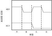
図14には、状態A乃至Dでの金属薄膜4B1に対するP偏光の光強度の応答と、金属薄膜4C1に対するP偏光の光強度の応答とが示されている。図14に示すように、状態Aでは、金属薄膜4B1も、金属薄膜4C1についても応答(光強度の低下)がない。また、状態Bでは、金属薄膜4B1について応答が現れ、金属薄膜4C1については応答がない。また、状態Cでは、金属薄膜4B1では応答がなく、金属薄膜4C1について応答が現れる。また、状態Dは、金属薄膜4B1及び金属薄膜4C1の両方に応答が現れる。
したがって、測定部10は、このような金属薄膜4B1に対するP偏光の光強度の応答測と、金属薄膜4C1に対するP偏光の光強度の応答とに基づいて、状態A~Dのうち、いずれの状態であるかを判定することにより、試料12の屈折率に加え、試料12の位置情報も検出することができる。
ここで、パイプライン11内に固定した2mm角のガラス棒4Aの側面4Aa,4Abに、3cmの長さで厚さ45nmの金属(金)薄膜4B1,4C1を形成した。金属(金)薄膜4B1と金属(金)薄膜4C1との間は3cmとした。そして、このガラス棒4Aを用いて、受光部8の前に設置した偏光板6で偏光を選択しつつ、試料12として0~30%のエタノール水溶液を金属(金)薄膜4B1側からパイプライン11に流したときの応答の変化を測定した。
図18では、この応答の変化が示されている。図18には、P偏光(金属(金)薄膜4B1に対するP偏光)の受光結果と、S偏光(金属(金)薄膜4C1に対するP偏光)の受光結果とが示されている。図18に示すように、P偏光及びS偏光ともに、エタノール水溶液の濃度が上がれば上がるほど、規格化透過光強度が低下している。
図19では、20%から30%にエタノール溶液の濃度を変えた時間T(図18参照)における応答の変化を拡大して示している。図19に示すように、エタノールの濃度が20%から30%へ変化する間に、状態A(図13A,図14)から、状態B(図13B,図14)に遷移し、さらに状態D(図13D,図14)に遷移していることが示されている。
なお、本実施の形態では、2つの側面4Aa,4Abに形成する金属薄膜の金属を同じ種類(金)としたが、本発明はこれには限られず、側面毎に異なる金属を用いるようにしてもよい。また、側面毎に、金属薄膜の膜厚や長さを変えるようにしてもよい。
実施の形態4.
次に、本発明の実施の形態4について説明する。
次に、本発明の実施の形態4について説明する。
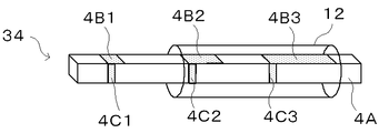
本実施の形態では、図15に示すように、屈折率測定装置1の構成は、導波路部材4に代えて、導波路部材34を備えている点が、上記実施の形態1と異なる。具体的には、導波路部材34では、面積がそれぞれ異なる複数の金属薄膜が、長手方向に沿って形成されている。
屈折率が同一である試料12に対する屈折率測定装置1の応答の変化量(規格化透過光強度の変化量)は、蒸着している金属の面積に比例すると考えられる。そこで、本実施の形態では、図15に示すように、ガラス棒4Aの側面4Aaの長手方向に、複数の金属薄膜4B1,4B2,4B3を設け、金属薄膜4B1,4B2,4B3の蒸着面積に、1:2:4(面積比が2の乗数となる)というように差を付け、測定部10で、応答(光強度)の変化量の比を取ることで試料12の位置情報を検出する。なお、本実施の形態では、ガラス棒4Aの側面4Abの長手方向にも金属薄膜4C1,4C2,4C3が設けられている。金属薄膜4C1,4C2,4C3は、同じ面積で、蒸着により形成されている。金属薄膜4B1と金属薄膜4C1との面積比は4:2であり、金属薄膜4B2と金属薄膜4C2との面積比は8:2であり、金属薄膜4B3と金属薄膜4C3との面積比は16:2である。
ここで、図16Aに示すように、金属薄膜4B1,4C1の周囲にのみ試料12が存在している状態を、状態Aとする。また、図16Bに示すように、金属薄膜4B1,4C1の周囲及び金属薄膜4B2,4C2の周囲に試料12が存在している状態を、状態Bとする。また、図16Cに示すように、金属薄膜4B2,4C2の周囲及び金属薄膜4B3,4C3の周囲に試料12が存在している状態を、状態Cとする。また、図16Dに示すように、金属薄膜4B3,4C3の周囲にのみ試料12が存在している状態を、状態Dとする。
状態Aの場合、側面4Aaに対するP偏光の光強度と、側面4Abに対するP偏光の光強度との変化量の比は、4:2(=2:1)となる。また、状態Bの場合、側面4Aaに対するP偏光の光強度と、側面4Abに対するP偏光の光強度との変化量の比は、12:4(=3:1)となる。また、状態Cの場合、側面4Aaに対するP偏光の光強度と、側面4Abに対するP偏光の光強度との変化量の比は、24:4(=6:1)となる。さらに、状態Dの場合、側面4Aaに対するP偏光の光強度と、側面4Abに対するP偏光の光強度との変化量の比は、16:2(=8:1)となる。
このように、側面4Aaに対するP偏光の光強度と、側面4Abに対するP偏光の光強度との変化量の比は、試料12の存在する位置によって一意に決まる。このため、測定部10は、側面4Aaに対するP偏光の光強度と、側面4Abに対するP偏光の光強度との変化量の比に基づいて、試料12の位置情報を検出することができる。
また、測定部10は、側面4Aaに対するP偏光の光強度の変化量又は側面4Abに対するP偏光の光強度の変化量を金属薄膜の面積で除算することで試料12の屈折率を検出することができる。従って、屈折率測定装置1を用いて、パイプライン11内の溶液の反応の追跡が可能となる。また、屈折率が温度でも変化することを利用して反応層中の異常反応(温度変化)の監視を行うことができる他、屈折率測定装置1を様々な用途に利用することができる。
本実施の形態では、金属薄膜の面積を長手方向で変更したが、本発明はこれには限られない。例えば、金属薄膜の種類、膜厚等を長手方向で変更するようにしてもよい。
以上詳細に説明したように、本実施の形態によれば、1本の導波路部材4だけで、表面プラズモン共鳴現象の発生に関連する状態がそれぞれ異なる側面4Aa,4Abで反射した光に基づく複数の測定結果を選択的に得ることができる。複数の測定結果には、側面4Aa,4Abの状態によって、外乱成分だけのものを含めたり、測定可能な屈折率の範囲が異なるものを含めたり、試料12等の位置情報を検出可能な情報を含めたりすることができる。したがって、複数の側面4Aa,4Ab各々での測定結果を組み合わせれば、試料12の屈折率の測定精度を向上するとともに測定範囲を広げることができるうえ、試料12等の位置情報を検出することができる。
なお、上記実施の形態では、導波路部材4の周方向で表面プラズモン共鳴現象の発生に関連する側面4Aa,4Abの状態が異なる場合について説明したが、本発明はこれには限られない。導波路部材4の周方向には表面プラズモン共鳴現象の発生に関連する側面の状態が均一であり、導波路部材4の長手方向にP偏光に対する応答が異なる金属薄膜が形成された導波路部材を採用するようにしてもよい。
上記実施の形態では、金属薄膜の金属を、金又は銀あるいはアルミニウムとしたが、本発明はこれには限られない。金属薄膜の金属として銅を用いてもよい。ここで、金属は、その用途に応じて適切に用いられる必要がある。例えば、銅は、腐食しやすく、硫化銅を作りやすいので、硫化銅を作りやすい環境で用いるのは適切ではない。また、銀は、塩化銀をつくりやすいので、塩化銀を作りやすい環境で用いるのは適切ではない。アルミニウムは表面に薄いアルミナを形成しているが、酸やアルカリと反応して腐食するので、酸性やアルカリ性の環境で用いるのは適切ではない。金は化合物を作りにくいので、反応しやすい環境で用いる場合においても最適である。
また、金属薄膜は、異なる金属から成る薄膜を積層したものであってもよい。
また、上記実施の形態では、LED3として、例えば、赤色の発光ダイオードを用いた。しかしながら、表面プラズモン共鳴現象が発生するのであれば、より短波長又は長波長の光を発生させるLEDを用いるようにしてもよい。
ここで、金属薄膜と光の波長との関係についてまとめる。このような関係が、金属薄膜の種類、光の波長を選択するうえで重要な要素となる。
(1)金の場合
・赤色、赤外線発光ダイオードを用いた場合、広い膜厚の範囲で良好な応答が得られる。
・波長による最小値屈折率の変化が非常に大きい。この変化は、膜厚が厚い方が顕著になる。
・短波長の光では、表面プラズモン共鳴現象は得られにくい。
(2)銀の場合
・金と比較して、応答が大きい。
・波長による最小値屈折率の変化が小さい。
・緑色LEDでも応答(表面プラズモン共鳴現象)が見られた。
(3)アルミニウムの場合
・金、銀と比較して、広い屈折率範囲でなだらかに透過光強度が変化する。すなわち透過光強度の感度が小さい。
・光強度の落ち込みと最小値の屈折率は、波長、膜厚が変わってもそれほど変化しない。
・短波長の光でも良好な応答を示す。
(1)金の場合
・赤色、赤外線発光ダイオードを用いた場合、広い膜厚の範囲で良好な応答が得られる。
・波長による最小値屈折率の変化が非常に大きい。この変化は、膜厚が厚い方が顕著になる。
・短波長の光では、表面プラズモン共鳴現象は得られにくい。
(2)銀の場合
・金と比較して、応答が大きい。
・波長による最小値屈折率の変化が小さい。
・緑色LEDでも応答(表面プラズモン共鳴現象)が見られた。
(3)アルミニウムの場合
・金、銀と比較して、広い屈折率範囲でなだらかに透過光強度が変化する。すなわち透過光強度の感度が小さい。
・光強度の落ち込みと最小値の屈折率は、波長、膜厚が変わってもそれほど変化しない。
・短波長の光でも良好な応答を示す。
また、LED3の光を、長波長から短波長まで広い波長帯域を含む光としてもよい。金属の種類によって感度のある屈折率は異なってくるので、本発明のように、導波路部材4の複数の側面各々に、異なる金属の薄膜を形成し、様々な波長の光を入射可能としておけば、測定可能な屈折率の範囲を大幅に広げることが可能となる。
多角形状のガラス棒は極めて製作し易く、使い捨ても可能である。このため、本発明は、測定精度を向上したり測定範囲を広げたりするのを容易にするだけでなく、コンタミネーションを防止するうえで好適である。
また、金属薄膜の上に直鎖の高分子から成るスペーサを設け、さらにその上にフッ素樹脂膜を選択膜として成膜するようにしてもよい。フッ素樹脂膜は分子サイズの穴が存在しており、揮発性物質を透過させる。例えば、日本酒等に含まれるアルコールを試料12とする場合、フッ素樹脂膜は、糖分や有機酸などを通さず、アルコール成分だけを金属薄膜上に通す。したがって、スペーサ、フッ素樹脂膜を設けることにより、アルコール濃度を正確に計測することができる。
試料12は、一般的には溶液(溶媒)中に含まれる成分となる。例えば、清酒、ワイン等の酒のアルコールなどを試料12とすることができる。また、エンジンオイル内に含まれるガソリンを試料12とすることも可能である。
また、偏光板6の代わりに偏光ビームスプリッタを配置して、偏光ビームスプリッタで分割された光を別々の受光部8で受光してそれぞれの光強度を検出するようにしてもよい。このようにすれば、側面が異なる2つの光強度を同時に検出することが可能となる。また、偏光板6を回転させるなどの選択部7における駆動機構も不要となる。
また、上記各実施の形態では、ガラス棒4Aの断面を矩形(正方形)としたが、これには限られない。ガラス棒4Aの断面形状は、長方形、菱形、台形であってもよい。また、ガラス棒4Aの断面形状は、3角形でもよいし、5角形以上の多角形であってもよい。法線方向が異なる少なくとも2つの平板状の側面があればよいのであって、その他の側面は曲面であってもよい。
なお、側面同士の法線方向が直交していない側面同士では、一方の光強度の測定結果に他方の光強度の測定結果の成分が混入する。この場合、測定部10は、両側面の成す角度での混入成分を算出し、一方の光強度の測定結果から算出した混入成分を差し引いて、差し引いた値を、真の光強度として算出するようにすればよい。
また、金属薄膜が形成された側面に対向する側面に金属薄膜を形成するようにしてもよい。
この発明は、この発明の広義の精神と範囲を逸脱することなく、様々な実施の形態及び変形が可能とされるものである。また、上述した実施の形態は、この発明を説明するためのものであり、この発明の範囲を限定するものではない。すなわち、この発明の範囲は、実施の形態ではなく、特許請求の範囲によって示される。そして、特許請求の範囲内及びそれと同等の発明の意義の範囲内で施される様々な変形が、この発明の範囲内とみなされる。
なお、本願については、2016年8月29日に出願された日本国特許出願2016-166544号を基礎とする優先権を主張し、本明細書中に日本国特許出願2016-166544号の明細書、特許請求の範囲、図面全体を参照として取り込むものとする。
本発明によれば、試料の屈折率の測定に利用することができる。例えば、焼酎の製造工程(蒸留、熟成、瓶詰め等)において、アルコール度数を測定する度数計に本発明を適用することができる。
1 屈折率測定装置、2 電源、3 発光ダイオード(LED)、4 導波路部材、4A ガラス棒、4Aa,4Ab 側面、4B,4B1,4B2,4B3 金属(金)薄膜、4C 金属(アルミニウム)薄膜、4C1,4C2,4C3 金属(金)薄膜、5 レンズ、6 偏光板、7 選択部、8 受光部、9 受光回路、9A コンデンサ、9B 抵抗、10 測定部、11 パイプライン、12 試料(測定対象)、14,24,34 導波路部材
Claims (6)
- 偏光方向が異なる複数の直線偏光成分を含む光を出射する投光部と、
前記投光部からの光を一端から入射し、表面プラズモン共鳴現象を発生させる金属薄膜が一部に形成された側面で全反射させた後、他端から出射する細長柱状の導波路部と、
前記導波路部から出射された光における特定の方向の直線偏光成分を抽出する偏光フィルタ部と、
前記偏光フィルタ部で抽出される光の直線偏光成分の偏光方向を選択する選択部と、
前記偏光フィルタ部で抽出された光の直線偏光成分の強度を検出する光強度検出部と、
前記光強度検出部で検出された光強度に基づいて、試料の屈折率を測定する測定部と、
を備え、
前記導波路部には、
入射した光に含まれる複数の直線偏光成分のいずれかがP偏光となり、P偏光に対する応答がそれぞれ異なる平面状の複数の側面が形成されている、
屈折率測定装置。 - 前記導波路部は、
前記複数の側面として、金属薄膜が形成された第1の側面と、金属薄膜が形成されていない第2の側面を有しており、
前記測定部は、
前記第1の側面に対応するP偏光を前記選択部で選択したときに前記光強度検出部で検出された第1の光強度と、前記第2の側面に対応するP偏光を前記選択部で選択したときに前記光強度検出部で検出された第2の光強度とに基づいて、試料の屈折率を測定する、
請求項1に記載の屈折率測定装置。 - 前記導波路部の前記複数の側面それぞれに形成された金属薄膜は、
側面毎に金属の種類又は膜厚が異なり、
前記測定部は、
複数の側面各々に対応するP偏光の光強度の測定結果に基づいて、試料の屈折率を測定する、
請求項1に記載の屈折率測定装置。 - 前記導波路部では、
前記金属薄膜が形成された長手方向に関する位置が側面毎に異なり、
前記測定部は、
複数の側面各々に対応するP偏光の光強度の測定結果に基づいて、試料の屈折率を測定するとともに、試料の位置情報を検出する、
請求項1に記載の屈折率測定装置。 - 前記導波路部では、
面積がそれぞれ異なる複数の金属薄膜が、長手方向に沿って形成されており、
前記測定部は、
複数の側面各々に対応するP偏光の光強度の測定結果に基づいて、試料の屈折率を測定するとともに、試料の位置情報を検出する、
請求項1に記載の屈折率測定装置。 - 細長柱状で、入射した光に含まれる複数の直線偏光成分のいずれかがP偏光となり、P偏光に対する応答がそれぞれ異なる平面状の複数の側面が設けられている導波路部材の一端から、偏光方向が異なる複数の直線偏光成分を含む投光部からの光を入射して、前記複数の側面で全反射させた後、前記導波路部材の他端から出射し、
前記導波路部から出射された光における特定の方向の直線偏光成分を選択的に抽出しつつ、選択的に抽出された光の直線偏光成分の強度を検出し、
検出された光強度に基づいて、試料の屈折率を測定する、
屈折率測定方法。
Priority Applications (1)
| Application Number | Priority Date | Filing Date | Title |
|---|---|---|---|
| JP2018537152A JP6801893B2 (ja) | 2016-08-29 | 2017-08-22 | 屈折率測定装置及び屈折率測定方法 |
Applications Claiming Priority (2)
| Application Number | Priority Date | Filing Date | Title |
|---|---|---|---|
| JP2016166544 | 2016-08-29 | ||
| JP2016-166544 | 2016-08-29 |
Publications (1)
| Publication Number | Publication Date |
|---|---|
| WO2018043194A1 true WO2018043194A1 (ja) | 2018-03-08 |
Family
ID=61300759
Family Applications (1)
| Application Number | Title | Priority Date | Filing Date |
|---|---|---|---|
| PCT/JP2017/029871 Ceased WO2018043194A1 (ja) | 2016-08-29 | 2017-08-22 | 屈折率測定装置及び屈折率測定方法 |
Country Status (2)
| Country | Link |
|---|---|
| JP (1) | JP6801893B2 (ja) |
| WO (1) | WO2018043194A1 (ja) |
Cited By (1)
| Publication number | Priority date | Publication date | Assignee | Title |
|---|---|---|---|---|
| WO2022204814A1 (en) * | 2021-03-31 | 2022-10-06 | Les Instruments Scientifiques Affinités Inc. | Lensless surface plasmon resonance instrument |
Citations (6)
| Publication number | Priority date | Publication date | Assignee | Title |
|---|---|---|---|---|
| US5485277A (en) * | 1994-07-26 | 1996-01-16 | Physical Optics Corporation | Surface plasmon resonance sensor and methods for the utilization thereof |
| JPH09329542A (ja) * | 1996-06-10 | 1997-12-22 | Kao Corp | 光沢測定方法及び光沢測定装置 |
| JP2002357538A (ja) * | 2001-05-31 | 2002-12-13 | Suzuki Motor Corp | プラズモンセンサ装置 |
| JP2003057168A (ja) * | 2001-08-20 | 2003-02-26 | Omron Corp | 路面判別装置及び同装置の設置調整方法 |
| JP2005321244A (ja) * | 2004-05-07 | 2005-11-17 | Shimadzu Corp | 光学的測定装置 |
| JP2009533696A (ja) * | 2006-04-17 | 2009-09-17 | バイオプティックス,エルエルシー | 偏光ベースの干渉型検出器 |
-
2017
- 2017-08-22 JP JP2018537152A patent/JP6801893B2/ja active Active
- 2017-08-22 WO PCT/JP2017/029871 patent/WO2018043194A1/ja not_active Ceased
Patent Citations (6)
| Publication number | Priority date | Publication date | Assignee | Title |
|---|---|---|---|---|
| US5485277A (en) * | 1994-07-26 | 1996-01-16 | Physical Optics Corporation | Surface plasmon resonance sensor and methods for the utilization thereof |
| JPH09329542A (ja) * | 1996-06-10 | 1997-12-22 | Kao Corp | 光沢測定方法及び光沢測定装置 |
| JP2002357538A (ja) * | 2001-05-31 | 2002-12-13 | Suzuki Motor Corp | プラズモンセンサ装置 |
| JP2003057168A (ja) * | 2001-08-20 | 2003-02-26 | Omron Corp | 路面判別装置及び同装置の設置調整方法 |
| JP2005321244A (ja) * | 2004-05-07 | 2005-11-17 | Shimadzu Corp | 光学的測定装置 |
| JP2009533696A (ja) * | 2006-04-17 | 2009-09-17 | バイオプティックス,エルエルシー | 偏光ベースの干渉型検出器 |
Cited By (1)
| Publication number | Priority date | Publication date | Assignee | Title |
|---|---|---|---|---|
| WO2022204814A1 (en) * | 2021-03-31 | 2022-10-06 | Les Instruments Scientifiques Affinités Inc. | Lensless surface plasmon resonance instrument |
Also Published As
| Publication number | Publication date |
|---|---|
| JPWO2018043194A1 (ja) | 2019-08-08 |
| JP6801893B2 (ja) | 2020-12-16 |
Similar Documents
| Publication | Publication Date | Title |
|---|---|---|
| US9089842B2 (en) | Multi-modal surface plasmon polariton—raman scattering based bio-detection | |
| JP6581600B2 (ja) | 試料のエッチング深さをその場(in situ)測定するためのグロー放電分光分析の方法およびシステム | |
| US9841376B2 (en) | High sensitivity metamaterial nano-sensing system with ultra-narrow line width spectral response | |
| JP2008224240A (ja) | 全反射減衰型光学プローブおよびそれを用いた水溶液分光測定装置 | |
| Tellez et al. | Atomically flat symmetric elliptical nanohole arrays in a gold film for ultrasensitive refractive index sensing | |
| JP2017522542A (ja) | 層深さの大きい導波路の特性を評価する、プリズム結合システムおよび方法 | |
| SE1150498A1 (sv) | Flerkanalig ytplasmonresonanssensor utnyttjande strålprofilsellipsometri | |
| CN105823732B (zh) | 用于确定介质的吸收特性的方法、装置和传感器 | |
| US20170219571A1 (en) | Enhanced surface plasmon resonance method | |
| CN103884683B (zh) | 基于f-p半导体激光器和薄膜f-p滤光片级联的光学传感器 | |
| TWI716422B (zh) | 從一樣本堆疊中判斷層的厚度的方法與組件 | |
| CN102243175A (zh) | 一种基于椭球反射镜光收集结构的表面等离子体共振光检测装置 | |
| CN108885176A (zh) | 具有纳米多孔表面层的波导传感器 | |
| CN112703391A (zh) | 浓度测定方法 | |
| JP6801893B2 (ja) | 屈折率測定装置及び屈折率測定方法 | |
| JP2005321244A (ja) | 光学的測定装置 | |
| CN101413827A (zh) | 利用古斯汉欣位移特性检测激光波长的方法 | |
| JP2011196766A (ja) | 光透過性を有する被測定物の形状測定方法 | |
| TW201305530A (zh) | 小角度及小位移之量測方法及其裝置 | |
| JP4572244B2 (ja) | 表面プラズモンセンサー | |
| KR20130110900A (ko) | 표면 플라즈몬 공명을 이용한 다층 박막 센서 | |
| CN107504912A (zh) | 厚度测试方法及装置 | |
| JP2007040981A (ja) | ウエハ温度測定方法及びウエハ温度測定装置 | |
| JP2016114532A (ja) | 光熱変換分光分析装置 | |
| JP2013250117A (ja) | 水素検出素子および水素センサ |
Legal Events
| Date | Code | Title | Description |
|---|---|---|---|
| 121 | Ep: the epo has been informed by wipo that ep was designated in this application |
Ref document number: 17846201 Country of ref document: EP Kind code of ref document: A1 |
|
| ENP | Entry into the national phase |
Ref document number: 2018537152 Country of ref document: JP Kind code of ref document: A |
|
| NENP | Non-entry into the national phase |
Ref country code: DE |
|
| 122 | Ep: pct application non-entry in european phase |
Ref document number: 17846201 Country of ref document: EP Kind code of ref document: A1 |