WO2018037824A1 - 点火プラグ - Google Patents
点火プラグ Download PDFInfo
- Publication number
- WO2018037824A1 WO2018037824A1 PCT/JP2017/027251 JP2017027251W WO2018037824A1 WO 2018037824 A1 WO2018037824 A1 WO 2018037824A1 JP 2017027251 W JP2017027251 W JP 2017027251W WO 2018037824 A1 WO2018037824 A1 WO 2018037824A1
- Authority
- WO
- WIPO (PCT)
- Prior art keywords
- layer
- ferrite
- spark plug
- recess
- peripheral surface
- Prior art date
- Legal status (The legal status is an assumption and is not a legal conclusion. Google has not performed a legal analysis and makes no representation as to the accuracy of the status listed.)
- Ceased
Links
Images


Classifications
-
- F—MECHANICAL ENGINEERING; LIGHTING; HEATING; WEAPONS; BLASTING
- F02—COMBUSTION ENGINES; HOT-GAS OR COMBUSTION-PRODUCT ENGINE PLANTS
- F02P—IGNITION, OTHER THAN COMPRESSION IGNITION, FOR INTERNAL-COMBUSTION ENGINES; TESTING OF IGNITION TIMING IN COMPRESSION-IGNITION ENGINES
- F02P13/00—Sparking plugs structurally combined with other parts of internal-combustion engines
-
- H—ELECTRICITY
- H01—ELECTRIC ELEMENTS
- H01T—SPARK GAPS; OVERVOLTAGE ARRESTERS USING SPARK GAPS; SPARKING PLUGS; CORONA DEVICES; GENERATING IONS TO BE INTRODUCED INTO NON-ENCLOSED GASES
- H01T13/00—Sparking plugs
- H01T13/02—Details
- H01T13/04—Means providing electrical connection to sparking plugs
- H01T13/05—Means providing electrical connection to sparking plugs combined with interference suppressing or shielding means
Definitions
- the present specification relates to a spark plug.
- spark plugs have been used in internal combustion engines.
- Various techniques have been proposed to suppress radio noise generated by ignition. For example, a technique for providing a resistor in the shaft hole of an insulator has been proposed. In addition, a technique for providing a magnetic body in the shaft hole of the insulator has been proposed.
- the present specification discloses a technique capable of suppressing radio noise.
- a cylindrical insulator having an axial hole extending in the direction of the axis, a cylindrical metal shell disposed on the outer periphery of the insulator, and a shaft disposed on the rear end side in the axial hole
- a terminal fitting having a portion and a terminal portion exposed from the shaft hole, a center electrode having at least a portion of itself disposed on a tip side in the shaft hole, and the center electrode and the terminal in the shaft hole
- a spark plug comprising: a connecting portion that electrically connects the metal fitting; and a portion of the shaft portion that is closer to the rear end side than the rear end of the metal shell is recessed inward in the radial direction.
- the depth of the recess is 50 ⁇ m or more, and the angle formed by two inclined surfaces facing each other across the bottom of the recess is 150 degrees or less, and the plurality of the plurality
- the length in the direction of the axis of the portion where the recess is formed Is a layer containing a ferrite containing at least one of Ni, Zn, Cu, Ba, Ca, Mg, Mn, and Y, in at least one of the recesses, Spark plug.
- a portion on the rear end side of the rear end of the metal shell in the shaft portion arranged in the shaft hole of the insulator, that is, the insulator is interposed between the terminal metal and the metal shell.
- a plurality of recesses are provided in a portion where high-frequency current is difficult to flow. Therefore, the plurality of recesses can appropriately suppress radio wave noise. Further, since at least one of the recesses is provided with a layer containing ferrite containing at least one of Ni, Zn, Cu, Ba, Ca, Mg, Mn, and Y, the radio noise is further increased. Can be suppressed. *
- the current that causes radio wave noise is concentrated on the outer peripheral surface of the recess, and thus in the vicinity of the layer containing ferrite, so that radio wave noise can be further suppressed.
- the shaft portion of the terminal fitting forms at least a part of the outer peripheral surface of the shaft portion including the outer peripheral surface of the concave portion.
- a frequency of 1 MHz calculated according to the following formula when assuming that the outer layer and an inner layer arranged on the inner peripheral side of the outer layer have an absolute permeability ⁇ of 0.0001 [H / m]
- the skin depth d at f is the reference skin depth
- the reference skin depth of the outer layer is shallower than the reference skin depth of the inner layer.
- Angular frequency 2 ⁇ ⁇ ⁇ ff: Frequency [Hz]
- ⁇ Absolute permeability [H / m]
- the current that causes radio wave noise is concentrated on the outer peripheral surface of the recess, and thus in the vicinity of the layer containing ferrite, so that radio wave noise can be further suppressed.
- an ignition device using an ignition plug or an ignition plug an internal combustion engine equipped with the ignition plug, or an ignition plug
- an internal combustion engine equipped with the ignition plug or an ignition plug
- an ignition plug This can be realized in an aspect of an internal combustion engine or the like equipped with the used ignition device.
- FIG. 6 is a cross-sectional view of a recess forming part 45. It is a fragmentary sectional view of another embodiment of a terminal metal fitting. It is a graph which shows the outline
- FIG. 1 is a cross-sectional view of a spark plug 100 as an embodiment.
- a center axis CL also referred to as “axis line CL”
- axis line CL the direction parallel to the central axis CL
- a direction perpendicular to the axis CL is also referred to as a “radial direction”.
- the lower direction in FIG. 1 the directions parallel to the central axis CL, the lower direction in FIG.
- the tip direction Df is a direction from the terminal fitting 40 described later toward the center electrode 20. 1 is referred to as the front end side of the spark plug 100, and the rear end direction Dfr side in FIG. 1 is referred to as the rear end side of the spark plug 100. *
- the spark plug 100 includes a cylindrical insulator 10 having a through-hole 12 (also referred to as a shaft hole 12) extending along the axis CL, a center electrode 20 held on the tip side of the through-hole 12, and the through-hole 12.
- the terminal fitting 40 held on the rear end side, the resistor 74 disposed between the center electrode 20 and the terminal fitting 40 in the through hole 12, and the resistor 74 and the center electrode 20 are electrically connected.
- a large-diameter portion 14 having the largest outer diameter is formed at the approximate center in the axial direction of the insulator 10.
- a rear end side body portion 13 is formed on the rear end side from the large diameter portion 14.
- a front end side body portion 15 having an outer diameter smaller than that of the rear end side body portion 13 is formed on the front end side of the large diameter portion 14.
- a further reduced diameter portion 16 and a leg portion 19 are formed in this order toward the distal end side further on the distal end side than the distal end side body portion 15.
- the outer diameter of the reduced outer diameter portion 16 gradually decreases toward the front direction Df. In the vicinity of the reduced outer diameter portion 16 (in the example of FIG.
- the front end side body portion 15), a reduced inner diameter portion 11 is formed in which the inner diameter gradually decreases in the front direction Df.
- the insulator 10 is preferably formed in consideration of mechanical strength, thermal strength, and electrical strength.
- the insulator 10 is formed by firing alumina (other insulating materials can also be used). is there). *
- the center electrode 20 is a rod-shaped member extending from the rear end side toward the front end side.
- the center electrode 20 is disposed at the end portion on the front direction Df side in the through hole 12 of the insulator 10.
- the center electrode 20 is joined (for example, laser welded) to the head portion 24 having the largest outer diameter, the shaft portion 27 formed on the front direction Df side of the head portion 24, and the tip of the shaft portion 27. And a first chip 29.
- the outer diameter of the head 24 is larger than the inner diameter of the portion on the front direction Df side than the reduced inner diameter portion 11 of the insulator 10.
- the surface on the front direction Df side of the head 24 is supported by the reduced inner diameter portion 11 of the insulator 10.
- the shaft portion 27 extends in the forward direction Df parallel to the axis line CL.
- the shaft portion 27 includes an outer layer 21 and a core portion 22 disposed on the inner peripheral side of the outer layer 21.
- the outer layer 21 is made of, for example, an alloy containing nickel as a main component.
- the main component means a component having the highest content (% by weight).
- the core portion 22 is formed of a material having a higher thermal conductivity than the outer layer 21 (for example, an alloy containing copper as a main component).
- the first chip 29 is made of a material having higher durability against discharge than the shaft portion 27 (for example, at least one selected from noble metals such as iridium (Ir) and platinum (Pt), tungsten (W), and those metals. Alloy).
- a part of the center electrode 20 on the tip side including the first tip 29 is exposed from the shaft hole 12 of the insulator 10 to the front direction Df side. Note that at least one of the core portion 22 and the first chip 29 may be omitted. Further, the entire center electrode 20 may be disposed in the shaft hole 12. *
- the terminal fitting 40 is a rod-shaped member extending in parallel with the axis CL.
- the terminal fitting 40 is formed using a conductive material.
- the terminal fitting 40 is formed using a metal containing iron as a main component. Components other than iron may include conductive substances (for example, metals such as molybdenum, chromium, and manganese, and conductive compounds such as carbides).
- the terminal fitting 40 includes a cap mounting portion 49, a flange portion 48, and a shaft portion 41, which are arranged in order in the front direction Df.
- the cap mounting portion 49 is exposed outside the shaft hole 12 on the rear end side of the insulator 10.
- a plug cap connected to a high voltage cable (not shown) is attached to the cap attaching portion 49, and a high voltage for generating spark discharge is applied.
- the cap mounting part 49 is an example of a terminal part to which a high voltage cable is connected.
- the shaft portion 41 is inserted on the rear direction Dfr side of the shaft hole 12 of the insulator 10.
- the surface on the front direction Df side of the flange portion 48 is in contact with the rear end 10 e that is the end on the rear direction Dfr side of the insulator 10. *
- the shaft portion 41 is provided with a recess forming portion 45. Although not shown in FIG. 1, a plurality of recesses that are recessed inward in the radial direction are formed on the outer peripheral surface of the recess forming portion 45.
- the recess forming portion 45 is provided to suppress electrical noise (also referred to as radio wave noise). Details of the recess forming portion 45 will be described later. *
- a resistor 74 for suppressing electrical noise is disposed between the terminal fitting 40 and the center electrode 20.
- the resistor 74 is formed using a conductive material (for example, a mixture of glass, carbon particles, and ceramic particles).
- a first seal portion 72 is disposed between the resistor 74 and the center electrode 20, and a second seal portion 76 is disposed between the resistor 74 and the metal shell 50.
- These seal portions 72 and 76 are formed using a conductive material (for example, a mixture of metal particles and the same glass as that included in the material of the resistor 74).
- the center electrode 20 is electrically connected to the terminal fitting 40 by the first seal portion 72, the resistor 74, and the second seal portion 76.
- the entirety of the first seal portion 72, the resistor 74, and the second seal portion 76 that electrically connect the terminal fitting 40 and the center electrode 20 within the shaft hole 12 of the insulator 10 is also referred to as a connection portion 200.
- the center electrode 20 When manufacturing the spark plug 100, the center electrode 20 is inserted from the opening 10 q on the rear direction Dfr side of the insulator 10. The center electrode 20 is disposed at a predetermined position in the through hole 12 by being supported by the reduced inner diameter portion 11 of the insulator 10. Next, the material powder of each of the first seal portion 72, the resistor 74, and the second seal portion 76 and the molding of the charged powder material are performed in the order of the members 72, 74, and 76. The powder material is put into the through hole 12 through the opening 10q.
- the insulator 10 is heated to a predetermined temperature higher than the softening point of the glass component contained in the material powder of the members 72, 74, and 76, and is heated to the predetermined temperature from the opening 10 q of the terminal fitting 40.
- the shaft portion 41 is inserted into the through hole 12.
- the material powders of the members 72, 74, and 76 are compressed and sintered to form the members 72, 74, and 76.
- the terminal fitting 40 is fixed to the insulator 10. *
- the metal shell 50 is a cylindrical member having a through hole 59 extending along the axis CL.
- the insulator 10 is inserted into the through hole 59 of the metal shell 50, and the metal shell 50 is fixed to the outer periphery of the insulator 10.
- the metal shell 50 is formed using a conductive material (for example, a metal such as low carbon steel). A part of the insulator 10 on the front direction Df side is exposed outside the through hole 59. Further, a part of the insulator 10 on the rear direction Dfr side is exposed outside the through hole 59. *
- the metal shell 50 has a tool engaging part 51 and a body part 52.
- the tool engaging portion 51 is a portion into which a spark plug wrench (not shown) is fitted.
- the trunk portion 52 is a portion including the tip of the metal shell 50.
- a screw portion 57 for screwing into a mounting hole of an internal combustion engine (for example, a gasoline engine) is formed.
- a flange-like flange portion 54 protruding outward in the radial direction is formed between the threaded portion 57 and the flange portion 54 of the body portion 52.
- the gasket 90 is formed, for example, by bending a metal plate-like member, and is crushed and deformed when the spark plug 100 is attached to the engine head. Due to the deformation of the gasket 90, the gap between the spark plug 100 (specifically, the surface on the front direction Df side of the flange portion 54) and the engine head is sealed, and leakage of combustion gas is suppressed.
- the body portion 52 of the metal shell 50 is formed with a reduced inner diameter portion 56 whose inner diameter gradually decreases toward the distal end side.
- the front end side packing 8 is sandwiched between the reduced inner diameter portion 56 of the metal shell 50 and the reduced outer diameter portion 16 of the insulator 10.
- the front end side packing 8 is, for example, a plate ring made of iron (other materials (for example, metal materials such as copper) can also be used). *
- a thin caulking portion 53 is formed on the rear end side of the metal shell 50 from the tool engaging portion 51. Further, a thin buckled portion 58 is formed between the flange portion 54 and the tool engaging portion 51. Annular ring members 61 and 62 are inserted between the inner peripheral surface of the metal shell 50 from the tool engaging portion 51 to the caulking portion 53 and the outer peripheral surface of the rear end side body portion 13 of the insulator 10. ing. Further, the talc 70 powder is filled between the ring members 61 and 62.
- the buckling portion 58 is deformed outward (buckling) with the addition of compressive force, and as a result, the metal shell 50 And the insulator 10 are fixed.
- the talc 70 is compressed during the caulking process, and the airtightness between the metal shell 50 and the insulator 10 is improved.
- the packing 8 is pressed between the reduced outer diameter portion 16 of the insulator 10 and the reduced inner diameter portion 56 of the metal shell 50, and seals between the metal shell 50 and the insulator 10.
- the ground electrode 30 has a rod-shaped main body portion 37 and a second tip 39 attached to the tip end portion 34 of the main body portion 37.
- One end portion 33 (also referred to as a base end portion 33) of the main body portion 37 is joined to the distal end surface 55 of the metal shell 50 (for example, resistance welding).
- the main body portion 37 extends from the base end portion 33 joined to the metal shell 50 in the distal direction Df, bends toward the central axis CL, and reaches the distal end portion 34.
- the second tip 39 is fixed to a portion on the rear direction Dfr side of the tip portion 34 (for example, laser welding).
- the second tip 39 of the ground electrode 30 and the first tip 29 of the electrode 20 form a gap g.
- the second chip 39 is made of a material having higher durability against discharge than the main body 37 (for example, a noble metal such as iridium (Ir) or platinum (Pt), tungsten (W), or at least one selected from these metals). Alloy).
- the main body portion 37 includes an outer layer 31 and an inner layer 32 disposed on the inner peripheral side of the outer layer 31.
- the outer layer 31 is formed of a material (for example, an alloy containing nickel) that has better oxidation resistance than the inner layer 32.
- the inner layer 32 is made of a material (for example, pure copper, copper alloy, etc.) having a higher thermal conductivity than the outer layer 31. Note that at least one of the inner layer 32 and the second chip 39 may be omitted. *
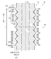
- FIG. 2 is a cross-sectional view of the recess forming portion 45 provided in the shaft portion 41 of the terminal fitting 40.
- This sectional view is a flat section including the axis CL.
- a plurality of recesses 300 that are recessed inward in the radial direction are formed on the outer peripheral surface of the recess forming portion 45.
- the recess forming portion 45 is formed in a part of the shaft portion 41.
- each recess 300 is an annular groove that goes around the axis CL on the outer peripheral surface of the shaft 41. *
- each recess 300 is formed of a bottom portion 310 and two inclined surfaces 320 and 330 that face each other with the bottom portion 310 interposed therebetween.
- the first inclined surface 320 is an inclined surface that is inclined toward the front direction Df when the inclined surface is traced from the inner side to the outer side in the radial direction.
- a first inclined surface 320 is connected to the front portion Df side of the bottom portion 310.
- the second inclined surface 330 is an inclined surface that is inclined toward the rear direction Dfr when the inclined surface is traced from the inner side to the outer side in the radial direction.
- a second inclined surface 330 is connected to the rear direction Dfr side of the bottom portion 310.
- the connection portion 340 forms a top portion that projects outward in the radial direction (hereinafter also referred to as the top portion 340).
- the recess forming portion 45 forms a wave-like portion in which the bottom portion 310 and the top portion 340 (in other words, the recess portion 300 and the convex portion formed by the top portion 340) are alternately arranged in the front direction Df. is doing.
- An outer peripheral surface 41 s in the drawing indicates an outer peripheral surface of a portion of the shaft portion 41 where the concave portion forming portion 45 is not provided.
- the bottom portion 310 is located on the radially inner side with respect to the outer peripheral surface 41s
- the top portion 340 is located on the outer side in the radial direction with respect to the outer peripheral surface 41s.
- Various methods can be adopted as a method for forming the plurality of bottom portions 310 and the plurality of top portions 340 and, in turn, the concave portion forming portion 45 for forming the plurality of concave portions 300 in the shaft portion 41. For example, so-called rolling may be employed.
- the shaft portion is rotated by rotating the roller and the shaft portion 41 in a state in which the roller having a portion obtained by inverting the shape of the recess forming portion 45 is pressed against the shaft portion 41 of the terminal fitting 40.
- a recess forming part 45 may be formed on 41.
- Such processing is also called knurling. *
- a length L in the drawing is a length in a direction parallel to the axis CL of the recess forming portion 45. As shown in the drawing, the length L of the recess forming portion 45 is between the top portion 341 on the most front direction Df side and the top portion 342 on the most rearward direction Dfr side among the plurality of top portions 340 of the recess forming portion 45. The distance in the direction parallel to the axis CL. *
- An angle Ang in the drawing is an angle formed by two inclined surfaces 320 and 330 facing each other with the bottom 310 of the recess 300 interposed therebetween.
- the depth 300 ⁇ / b> D is a depth in the radial direction of the recess 300, and is a distance in a direction perpendicular to the axis line CL between the adjacent top portion 340 and bottom portion 310.
- a ferrite-containing layer 400 is disposed in each of the plurality of recesses 300 (hereinafter referred to as a ferrite layer 400).
- a manufacturing method of the terminal fitting 40 having such a ferrite layer 400 various methods can be adopted. For example, the following method can be employed.
- a terminal fitting before the recess forming portion 45 is formed is prepared (for example, forging or cutting).
- the prepared terminal fitting has a shaft portion, a flange portion 48, and a cap mounting portion 49.
- a recess forming portion 45 (that is, a plurality of recesses 300) is formed on the shaft portion of the terminal fitting by rolling or the like.
- a slurry containing ferrite powder is applied to the outer peripheral surface of the formed recess forming portion 45. Thereby, the slurry containing ferrite adheres to the outer surface of each recess 300.
- the terminal fitting to which the slurry is attached is heated. Thereby, the fired ferrite layer 400 is formed in the recess 300 (that is, on the outer peripheral surface of the recess 300). Thus, the terminal fitting 40 is completed.
- Such a plurality of recesses 300 can suppress electrical noise during discharge.
- an alternating current can flow between the terminal fitting 40 and the metallic shell 50.
- Such AC current generates radio noise.
- the alternating current flows through a conductor, the alternating current flows near the surface of the conductor (also called the skin effect). Therefore, when an alternating current flows through the shaft portion 41 of the terminal fitting 40, an alternating current flows near the outer peripheral surface of the shaft portion 41.
- the shape of the outer peripheral surface of the recess forming portion 45 of the shaft portion 41 is a shape in which the first inclined surface 320 and the second inclined surface 330 are alternately repeated toward the front direction Df.
- the bottom portion 310 and the top portion 340 are alternately repeated (this shape can also be called a wave shape). Therefore, in this embodiment, the path length of the alternating current flowing along the outer peripheral surface of the shaft portion 41 is longer than that in the case where the outer peripheral surface of the shaft portion 41 is parallel to the axis CL. Thereby, the loss when an alternating current flows through the shaft portion 41 is increased. As a result, the plurality of recesses 300 can suppress alternating current, and thus radio wave noise.
- the sharp part like the top part 340 is provided in the conductor, the current density is concentrated on the sharp part. Therefore, the loss when the alternating current flows through the shaft portion 41 is larger than when the current flows in a wide range (for example, when the outer peripheral surface of the shaft portion 41 is parallel to the axis CL). As a result, the plurality of recesses 300 can suppress alternating current, and thus radio wave noise.
- a ferrite layer 400 is disposed in the recess 300.
- the ferrite layer 400 is disposed near the outer peripheral surface of the recess 300, that is, near the path through which the alternating current flows.
- Such a ferrite layer 400 can suppress radio noise.
- the current path close to the ferrite layer 400 functions as an inductance element, thereby suppressing radio noise.
- the recess forming portion 45 (that is, the plurality of recesses 300) is the end of the shaft portion 41 of the terminal fitting 40 on the rear direction Dfr side. It is formed in a portion on the rear direction Dfr side with respect to a certain rear end 50e.
- the reason for this is as follows. On the front direction Df side with respect to the rear end 50 e of the metal shell 50, the shaft portion 41 of the terminal metal fitting 40 and the metal shell 50 form a capacitor that sandwiches the insulator 10. The impedance of the capacitor decreases as the frequency increases. Therefore, at the time of discharging, a high frequency current can flow between the shaft portion 41 and the metal shell 50 via the insulator 10.
- the recess forming portion 45 is formed in the portion of the shaft portion 41 where the current flows near the outer peripheral surface, that is, in the portion of the shaft portion 41 on the rear side Dfr side of the rear end 50e of the metal shell 50. Since it is provided, the recess forming part 45 can appropriately suppress radio wave noise.
- the length L of the recess forming portion 45 is the length of the recess forming portion 45 on the rear side Dfr side with respect to the rear end 50e of the metal shell 50.
- FIG. 3 is a partial cross-sectional view of another embodiment of a terminal fitting.
- FIG. 3 shows a cross-sectional view of the recess forming portion 45b as in FIG.
- the terminal fitting 40b according to the second embodiment can be used in place of the terminal fitting 40 according to the first embodiment shown in FIGS.
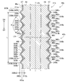
- the difference between the terminal fitting 40b of the second embodiment and the terminal fitting 40 of FIG. 2 is that the shaft portion 41b of the terminal fitting 40b of the second embodiment includes an outer layer 47 including the outer peripheral surface 41bs of the shaft portion 41b, and And an inner layer 46 disposed on the inner peripheral side.
- the structure of the other part of the terminal fitting 40b is the same as the structure of the corresponding part of the terminal fitting 40 of FIGS.
- the outer layer 47 is provided only on the shaft portion 41b. In the present embodiment, the outer layer 47 forms the entire outer peripheral surface of the shaft portion 41b.
- the terminal fitting 40b of the second embodiment has the same flange 48 and cap mounting portion 49 as the terminal fitting 40 of FIG. *
- the inner layer 46 is formed using a metal containing iron as a main component, like the shaft portion 41 in FIGS. 1 and 2.
- the outer layer 47 is a metal layer different from the inner layer 46.
- a conductive material for example, a metal such as nickel, copper, chromium, zinc, ⁇ iron, etc. that can suppress radio noise is used.
- the outer layer 47 covers the outer peripheral surface 46 s of the inner layer 46.
- a plurality of recessed portions 300x that are recessed inward in the radial direction and the outwardly protruding in the radial direction.
- a plurality of top portions 340x are formed.
- the outer layer 47 is provided so that the outer peripheral surface 46s of the inner layer 46 may be covered.
- the outer layer 47 forms a plurality of recesses 300 b and a plurality of top portions 340 b corresponding to the plurality of recesses 300 x and the plurality of top portions 340 x of the inner layer 46.
- the concave portion 300b of the outer layer 47 (that is, the concave portion 300b of the shaft portion 41b) is formed by a bottom portion 310b and two inclined surfaces 320b and 330b that face each other with the bottom portion 310b interposed therebetween. Similar to the first inclined surface 320 in FIG. 2, the first inclined surface 320b is an inclined surface that is inclined toward the front direction Df when the inclined surface is traced from the inner side to the outer side in the radial direction. A first inclined surface 320b is connected to the front portion Df side of the bottom portion 310b. Similarly to the second inclined surface 330 in FIG.
- the second inclined surface 330 b is an inclined surface that is inclined toward the rear direction Dfr when the inclined surface is traced from the inner side to the outer side in the radial direction.
- a second inclined surface 330b is connected to the rear direction Dfr side of the bottom portion 310b.
- the radially outer end of the first inclined surface 320b and the radially outer end of the second inclined surface 330b are connected to each other in the same manner as the inclined surfaces 320 and 330 of FIG.
- the top part 340b which protrudes toward the outer side of the direction is formed.
- the shape of the outer peripheral surface of the recessed portion forming portion 45b of the second embodiment is the same as the shape of the outer peripheral surface of the recessed portion forming portion 45 of FIG. 2, and the first inclined surface 320b and the second inclined surface 330b toward the front direction Df. Is a shape that repeats alternately, in other words, a shape in which the bottom portion 310b and the top portion 340b repeat alternately. *
- An outer peripheral surface 41bs in the drawing indicates an outer peripheral surface of a portion of the shaft portion 41b where the concave portion forming portion 45b is not provided.
- the bottom portion 310b is located on the radially inner side with respect to the outer peripheral surface 41bs
- the top portion 340b is located on the outer side in the radial direction with respect to the outer peripheral surface 41bs.
- the radial thickness of the outer layer 47 is approximately the same regardless of the position on the outer peripheral surface 46 s of the inner layer 46.
- the radial thickness of the outer layer 47 may vary depending on the position on the outer peripheral surface 46 s of the inner layer 46.
- the thickness at the bottom 310b may be thicker than the thickness at the top 340b.
- the length L in the drawing is the length in the direction parallel to the axis CL of the recess forming portion 45b. Similar to the length L in FIG. 2, the length L of the recess forming portion 45b is determined by selecting the top portion 341b on the most front side Df side and the top portion on the most back side Dfr side among the top portions 340b of the recess forming portion 45b. 342b is a distance in a direction parallel to the axis CL. In addition, the length L of the recessed part formation part 45b is the length of the recessed part formation part 45b in the back direction Dfr side rather than the rear end 50e (FIG. 1) of the metal shell 50. *
- An angle Ang in the drawing is an angle formed by two inclined surfaces 320b and 330b facing each other with the bottom 310b of the recess 300b interposed therebetween.
- the depth 300bD is a radial depth of the recess 300b, and is a distance in a direction perpendicular to the axis line CL between the adjacent top portion 340b and bottom portion 310b.
- the ferrite layer 400 is disposed as in the embodiment of FIG.
- various methods can be adopted. For example, the following method can be employed.
- a terminal fitting before the formation of the recess forming portion 45b and the outer layer 47 is prepared (for example, forging or cutting).
- the prepared terminal fitting has a shaft portion corresponding to the inner layer 46, a flange portion 48, and a cap mounting portion 49.
- a plurality of concave portions 300x and a plurality of top portions 340x are formed on the shaft portion of the terminal fitting by the same method (for example, rolling) as the method of forming the plurality of concave portions 300 and the plurality of top portions 340 in FIG. Thereby, the inner layer 46 is formed.
- An outer layer 47 is formed on the outer peripheral surface of the inner layer 46 (for example, plating). The formed outer layer 47 forms a plurality of recesses 300b and a plurality of top portions 340 corresponding to the plurality of recesses 300x and the plurality of top portions 340x of the inner layer 46 (that is, the recess forming portions 45b).
- a slurry containing ferrite powder is applied to the outer peripheral surface of the formed recess forming portion 45b. As a result, the slurry containing ferrite adheres to the outer surface of each recess 300b.
- the terminal fitting to which the slurry is attached is heated. Thereby, the fired ferrite layer 400 is formed in the recess 300b. Thus, the terminal fitting 40b is completed.
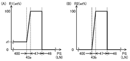
- FIG. 4 is a graph showing an outline of the relationship between the ratio of the main component of the outer layer 47 and the position on the cross section of FIG.
- the vertical axis indicates the ratios R1 and R2 (units are weight percent) of the main component of the outer layer 47.
- the horizontal axis represents the position PS on the line LN shown in the left part of the cross section of FIG.
- the line LN extends from the inner layer 46 to the ferrite layer 400 through the outer layer 47.
- the graph of FIG. 4A shows an example in which the main component of the outer layer 47 is also included in the ferrite of the ferrite layer 400.
- the main component of the outer layer 47 is nickel, and the ferrite contained in the ferrite layer 400 is a ferrite containing nickel (for example, NiFe 2 O 4 ).
- the ratio R ⁇ b> 1 is the ratio of the main component (for example, nickel) of the outer layer 47.
- the graph of FIG. 4B shows an example in which the main component of the outer layer 47 is not included in the ferrite of the ferrite layer 400.
- the main component of the outer layer 47 is copper, and the ferrite contained in the ferrite layer 400 is a ferrite not containing copper (for example, NiFe 2 O 4 ).
- the ratio R2 is the ratio of the main component (for example, copper) of the outer layer 47.
- the ratio R1 is zero wt% in the inner layer 46, and the ratio R1 is 100 wt% in the outer layer 47.
- the ratio R1 is a ratio rf corresponding to the composition of the ferrite (zero wt% ⁇ rf ⁇ 100 wt%).
- the ratio R1 smoothly changes from 100 wt% to the ratio rf from the outer layer 47 side toward the ferrite layer 400 side. .
- Such a region 43a can be formed when the ferrite layer 400 is fired (hereinafter, the region 43a is also referred to as an intermediate layer 43a).
- the intermediate layer 43a is formed. Further, the intermediate layer 43a is formed by forming a compound (for example, an oxide of the main component of the outer layer 47) with the main component of the outer layer 47 and another component (for example, a component included in the material of the ferrite layer 400). Is formed.
- a compound for example, an oxide of the main component of the outer layer 47
- another component for example, a component included in the material of the ferrite layer 400.
- Various methods can be adopted as a method of controlling the thickness of the intermediate layer 43a. For example, the intermediate layer 43a becomes thicker as the temperature during firing of the ferrite layer 400 is higher. By lowering the temperature during firing of the ferrite layer 400, the formation of the intermediate layer 43a can be suppressed.
- the ratio R2 is zero wt% in the inner layer 46, the ratio R2 is 100 wt% in the outer layer 47, and the ratio R2 is zero wt% in the ferrite layer 400.
- an intermediate layer 43 b is formed between the outer layer 47 and the ferrite layer 400.
- the ratio R2 smoothly changes from 100 wt% to zero wt% from the outer layer 47 side toward the ferrite layer 400 side.
- Such an intermediate layer 43b can be formed when the ferrite layer 400 is fired, similarly to the intermediate layer 43a of FIG. *
- the ratios R1 and R2 of the main component of the outer layer 47 are smaller than the ratios R1 and R2 in the outer layer 47 and higher than the ratios R1 and R2 in the ferrite layer 400. Since the ferrite layer 400 and the outer layer 47 are connected via the intermediate layers 43a and 43b, the intermediate layers 43a and 43b are omitted and the ferrite layer 400 is directly connected to the outer layer 47. Compared to, the adhesion between the ferrite layer 400 and the recess 300b can be improved. As a result, peeling of the ferrite layer 400 can be suppressed. *
- Evaluation Test Table 1 below shows the results of an evaluation test using a spark plug sample. In this evaluation test, 35 types of samples A1 to A27 and B1 to B8 were evaluated. *
- Table 1 shows the configuration of the recess, the configuration of the terminal material, the configuration of the outer layer 47, the configuration of the ferrite layer, the presence / absence of the intermediate layers 43a and 43b, and the noise characteristic test results for each sample. Yes.
- “ ⁇ ” is shown for the samples of FIGS. 1 and 2 that do not have the outer layer 47
- the composition of the outer layer 47 is shown for the sample of FIG.
- “*” is shown for a sample having an intermediate layer (for example, the intermediate layer 43a in FIG. 4A or the intermediate layer 43b in FIG. 4B), and the sample has an intermediate layer. For samples that do not, “-” is shown.
- samples A1 to A12 and the samples B1 to B8 are samples that do not have the outer layer 47 (FIGS. 1 and 2).
- Samples A13 to A27 are samples having the outer layer 47 (FIG. 3).
- samples A13 to A16 are samples that do not have an intermediate layer
- samples A17 to A27 are samples that have an intermediate layer. *
- the depths 300D and 300bD (unit is ⁇ m), the angle Ang (unit is degree), and the length L (unit is mm) described in FIGS. 2 and 3 are shown.
- the depths 300D and 300bD and the angle Ang are average values of the depths 300D and 300bD and the angle Ang of the plurality of recesses 300 and 300b in one cross section, respectively.
- the configuration of the material of the shaft portion 41 is shown for the sample of FIG. 2, and the configuration of the material of the inner layer 46 is shown for the sample of FIG. Specifically, the iron content (unit: wt%) and the skin depth (unit: ⁇ m) are shown.
- the skin depth is the skin depth d at a frequency f of 1 MHz calculated according to the following formula when the absolute permeability ⁇ is assumed to be 0.0001 [H / m]. *
- the skin depth indicates a measure of the depth from the surface of the portion where the current flows when an alternating current flows near the surface of the conductor.
- the smaller the skin depth the higher the current density near the surface of the conductor.
- the absolute permeability ⁇ of a metal is approximately zero at a frequency of 1 MHz or higher, and it is not easy to measure accurately.
- the skin depth d at a frequency of 1 MHz was calculated using 0.0001 [H / m] as a reference value of the absolute permeability ⁇ (hereinafter, this skin depth d is also referred to as the reference skin depth d). Call). Further, as shown in the above formula, the reference skin depth d is smaller as the volume resistivity ⁇ is smaller. *
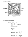
- FIG. 5 is an explanatory diagram showing a method for calculating the average particle diameter.
- the cross section of the ferrite layer 400 was mirror-polished and photographed with a SEM (scanning electron microscope) to obtain a 30 ⁇ m ⁇ 30 ⁇ m square cross-sectional image (also referred to as an SEM image).
- the acceleration voltage was set to 15 kV
- the magnification was set to 3000 times.
- FIG. 5A is a schematic diagram showing a state of ferrite particles observed in an SEM image. The average particle size was calculated by the following intercept method using such an SEM image. *
- ferrite particles intersecting with at least one of two diagonal lines DG1, DG2 (FIG. 5A) of a 30 ⁇ m ⁇ 30 ⁇ m square were selected. And about each selected particle
- the maximum diameter Dmax is a maximum value when the outer diameter of the particle CG is measured in all directions.
- the outer diameter of the particle CG on a straight line passing through the middle point of the major axis D1 and orthogonal to the major axis D1 was defined as the minor axis D2.
- the average value (D1 + D2) / 2 of the major axis D1 and the minor axis D2 was defined as the particle size Da (i) having only the target particle CG.
- “(i)” means the value of the i-th particle CG.
- the average particle diameter Dave is an average value of n particles CG that do not intersect with at least one of the diagonal lines DG1 and DG2, but the particle diameter Da (i). This average value was adopted as the average particle size in Table 1.
- the B8 sample is a sample that does not have a ferrite layer.
- the ferrite particle size was adjusted by adjusting the pulverization time of the ferrite powder material and the pulverization time of the slurry containing the ferrite powder material (the longer the pulverization time, the smaller the particle size). *
- the noise characteristic indicates the noise intensity and the evaluation result.
- the noise intensity was measured in accordance with JASO D002-2 (Japan Automobile Technical Association Transmission Standard D-002-2) “Automobile-Radio Noise Characteristics—Part 2: Measuring Method of Preventor Current Method”. Specifically, the spark plug sample was discharged by applying a voltage. And at the time of discharge, the electric current which flows through a terminal metal fitting was measured using the current probe, and the measured value was converted into dB for comparison. As noise, noise of two kinds of frequencies of 50 MHz and 300 MHz was measured. The intensity in the table indicates the intensity of noise with respect to a predetermined standard. The larger the value, the stronger the noise.
- the A evaluation indicates that the intensity is less than 73 dB, and the B evaluation indicates that the intensity is 73 dB or more.
- the evaluation result of noise of 300 Mhz A evaluation indicates that the intensity is less than 57 dB, and B evaluation indicates that the intensity is 57 dB or more.
- the distribution range of each parameter was as follows. 50 ⁇ m ⁇ depth 300D, 300 bD ⁇ 75 ⁇ m 22 degrees ⁇ angle Ang ⁇ 150 degrees 10 mm ⁇ length L ⁇ 26 mm 66 wt% ⁇ iron content ⁇ 92 wt% 18 ⁇ m ⁇ reference skin depth ⁇ 41 ⁇ m 0.7 ⁇ m ⁇ ferrite particle diameter ⁇ 3 .6 ⁇ m
- the evaluation result of 50 MHz noise was A evaluation
- the evaluation result of 300 MHz noise was A evaluation. *
- At least one parameter of depth 300D, angle Ang, and length L was outside the above distribution range of A1 to A27. Specifically, it is as follows.
- the depths 300D of B1, B4, B6, and B7 were 48, 49, 48, and 49 ( ⁇ m), respectively, and were all smaller than 50 ⁇ m.
- the angle Ang of B2 was 153 (degrees), which was larger than 150 degrees.
- the lengths L of B3, B5, B6, and B7 were all 9, 9, 9, 8 (mm), and were all smaller than 10 mm.
- the iron content of B1 to B8 and the reference skin depth were both within the above distribution range of A1 to A27.
- the evaluation result of 50 MHz noise was B evaluation
- the evaluation result of 300 MHz noise was B evaluation. *
- the noise intensity of each of A1 to A27 having the ferrite layer 400 was smaller than the noise intensity of B8 having no ferrite layer 400 at any frequency of 50 MHz and 300 MHz.
- noise can be suppressed by providing the ferrite layer 400.
- the noise intensity of each of A1 to A27 having a depth of 300D and 300bD of 50 ⁇ m or more is No. B1, B4, B6, and B7 having a depth of 300D smaller than 50 ⁇ m at any frequency of 50 MHz and 300 MHz.
- the reason why noise can be suppressed when the depths 300D and 300bD are deep is that when the depths 300D and 300bD are deep, the depths 300D and 300bD are shallow (particularly, the angle Ang and the length L are It is estimated that the total amount of ferrite disposed in the recesses 300 and 300b can be increased as compared to the case where the depths 300D and 300bD are made shallow without changing.
- Depths 300D and 300bD from A1 to A27 that realize good noise intensity are 50, 51, 54, 55, 56, 57, 58, 59, 60, 61, 62, 66, 68, 69 in ascending order. , 70, 71, 72, 73, 75 ( ⁇ m).
- a preferable range (a range from the lower limit to the upper limit) of the depths 300D and 300bD may be determined using the above 19 values. Specifically, any value of the above 19 values may be adopted as the lower limit of the preferable range of depths 300D and 300bD.
- the depth may be 50 ⁇ m or more.
- the depths 300D and 300bD may be 75 ⁇ m or less.
- the depths 300D and 300bD may be larger than 75 ⁇ m which is the maximum value among the above 19 values.
- the depths 300D and 300bD are preferably smaller than half of the outer diameters of the shaft portions 41 and 41b.
- the noise intensity of each of A1 to A27 having an angle Ang of 150 degrees or less is smaller than the noise intensity of the B2 sample having an angle Ang larger than 150 degrees at any frequency of 50 MHz and 300 MHz. It was. As described above, the reason why the noise can be suppressed when the angle Ang is small is that when the angle Ang is small, the angle Ang is large (particularly, the angle Ang is set without changing the depths 300D and 300bD and the length L). It is presumed that the path length of the alternating current flowing along the outer peripheral surfaces of the recess forming portions 45 and 45b of the shaft portions 41 and 41b of the terminal fittings 40 and 40b is longer than that of the case of increasing the size). *
- the angle Ang from A1 to A27 that realizes good noise intensity is 22, 45, 59, 65, 68, 69, 71, 75, 77, 79, 82, 85, 87, 88, 89, in ascending order. 93, 97, 100, 120, and 150 (degrees).
- a preferable range (range between the lower limit and the upper limit) of the angle Ang may be determined using the above 20 values. Specifically, any value among the above 20 values may be adopted as the upper limit of the preferable range of the angle Ang.
- the angle Ang may be 150 degrees or less.
- the angle Ang may be 22 degrees or more. *
- the noise intensity of each of A1 to A27 having a length L of 10 mm or more is any of B3, B5, B6, and B7 having a length L smaller than 10 mm at any frequency of 50 MHz and 300 MHz.
- the reason why noise can be suppressed when the length L is long is that when the length L is long, the length L is short (particularly, the length 300D, 300bD and the angle Ang are not changed).
- the length of the alternating current flowing along the outer peripheral surfaces of the concave portions 45, 45b of the shaft portions 41, 41b of the terminal fittings 40, 40b is longer than the case where the length L is shortened), and the total amount of ferrite It is presumed that this is because of the increase.
- the length L from No. A1 to No. A27 that realizes good noise intensity is 10, 11, 12, 13, 14, 15, 16, 17, 18, 19, 20, 21, 22, 26 (mm) in ascending order. )Met.
- a preferred range of the length L (a range from the lower limit to the upper limit) may be determined using the above 14 values. Specifically, any value of the above 14 values may be adopted as the lower limit of the preferable range of the length L. For example, the length L may be 10 mm or more. Moreover, you may employ
- the length L may be larger than 26 mm, which is the maximum value among the 14 values.
- the length L may be an arbitrary length equal to or less than a distance in a direction parallel to the axis CL from the rear end 50e of the metal shell 50 (FIG. 1) to the rear end 10e of the insulator 10.
- the composition of each of the ferrites A1 to A27 that achieves good noise intensity is as follows.
- the ferrite layer 400 includes a layer containing ferrite containing at least one of Ni, Zn, Cu, Ba, Ca, Mg, Mn, and Y. Is arranged. Noise could be suppressed by using the
- the reference skin depth was smaller as the iron content was higher.
- the reference skin depth was 30 ⁇ m or less.
- the reference skin depth was 32 ⁇ m or more.
- the noise intensity was smaller as the reference skin depth was smaller.
- the noise intensity at 50 MHz is 68 dB or less
- the noise intensity at 300 MHz is 51 dB or less.
- the noise intensity at 50 MHz is 69 dB or more
- the noise intensity at 300 MHz is 54 dB or more.
- the alternating current is concentrated in the vicinity of the outer peripheral surface of the conductor, so that the loss is greater than when the alternating current flows in a wide range. As a result, alternating current and thus radio wave noise is suppressed. In addition, since the alternating current is concentrated near the ferrite layer 400, the radio noise is further suppressed.
- the samples A13 to A27 are provided with the terminal fitting 40b of the embodiment of FIG. 3, and the outer layer 47 is formed on the outer peripheral surface of the inner layer 46.
- the composition of the outer layer 47 was any one of Ni, Cu, Cr, Zn, and ⁇ -Fe. Although detailed values are omitted, the volume resistivity ⁇ of these compositions was smaller than the volume resistivity ⁇ of the material of the inner layer 46 (metal including iron as a main component and other components). . That is, the volume resistivity ⁇ of the outer layer 47 was smaller than the volume resistivity ⁇ of the inner layer 46 for any of samples A13 to A27.
- the reference skin depth of the outer layer 47 which is a portion forming the outer peripheral surface of the recess forming portion 45b is shallower than the reference skin depth shown in Table 1 (reference skin depth of the inner layer 46).
- the reference skin depth shown in Table 1 of A13 to A27 having the outer layer 47 is 24 ⁇ m or less
- the reference skin depth of the outer layer 47 is 24 ⁇ m or less for these samples.
- the alternating current is further concentrated in the vicinity of the outer peripheral surface of the recess forming portion 45b (and in the vicinity of the ferrite layer 400) as compared with the case where the outer layer 47 is omitted. Therefore, it is estimated that radio noise is further suppressed.
- Reference skin depths of A1 to A27 that realize good noise intensity are 18, 19, 20, 21, 22, 23, 24, 25, 26, 28, 29, 30, 32, 34, 35 in ascending order. , 40, 41 ( ⁇ m).
- a preferable range (range between the lower limit and the upper limit) of the reference skin depth of the portion forming the outer peripheral surface of the recesses 300 and 300b may be determined using the above 17 values.
- the reference skin depth of the portion forming the outer peripheral surface of the recesses 300 and 300b is the reference skin depth of the shaft portion 41 in the embodiment of FIG. 2, and the reference skin depth of the outer layer 47 in the embodiment of FIG. It is the skin depth.
- any value of the above 17 values may be adopted.
- the reference skin depth may be 41 ⁇ m or less and may be 30 ⁇ m or less.
- the reference skin depth may be 18 ⁇ m or more.
- the reference skin depth may be smaller than 18 ⁇ m which is the minimum value among the above 17 values.
- a material having the smallest reference skin depth among materials that can be prepared for example, various metals
- the noise intensity was further reduced. Specifically, for the samples A17 to A27 having the intermediate layers 43a and 43b, the noise intensity at 50 MHz was 58 dB or less, and the noise intensity at 300 MHz was 43 dB or less. On the other hand, regarding the samples A1 to A16 having no intermediate layers 43a and 43b, the noise intensity at 50 MHz was 63 dB or more, and the noise intensity at 300 MHz was 45 dB or more. Thus, the reason why the noise intensity becomes small when the intermediate layers 43a and 43b are provided is estimated as follows.
- the adhesion between the ferrite layer 400 and the concave portion 300b (and thus the shaft portion 41b) is improved. Therefore, the alternating current that flows in the vicinity of the outer peripheral surface of the shaft portion 41b can flow through a portion closer to the ferrite (for example, the intermediate layers 43a and 43b). As a result, noise is suppressed.
- the average particle diameters of the ferrites Nos. A1 to A27 that realize good noise intensity are 0.7, 0.8, 0.9, 1.0, 1.9, 3.0, 3. It was 1, 3.2, 3.3, 3.4, 3.5, 3.6 ( ⁇ m).
- a preferred range (range between the lower limit and the upper limit) of the average particle diameter of ferrite may be determined using the above 12 values. Specifically, any value among the above 12 values may be adopted as the lower limit of the preferable range of the average particle diameter.
- the average particle size may be 0.7 ⁇ m or more.
- the average particle size may be 3.6 ⁇ m or less. *
- a preferable range of the average particle diameter of ferrite may be determined using the above three values. Specifically, any value among the above three values may be adopted as the lower limit of the preferable range of the average particle diameter.
- the average particle size may be 1.0 ⁇ m or more.
- the average particle size may be 3.0 ⁇ m or less.
- FIG. 6 is a cross-sectional view showing an example of a terminal fitting when a recess is formed by cutting.
- FIG. 6 shows a cross-sectional view of the recess forming portion 45c as in FIG.
- the terminal fitting 40c of the embodiment of FIG. 6 can be used in place of the terminal fittings 40 and 40b of FIGS. Also in the terminal fitting 40c of FIG.
- each of the plurality of recesses 300c is formed of a bottom portion 310c and two inclined surfaces 320c and 330c facing each other with the bottom portion 310c interposed therebetween.
- a ferrite layer 400 is disposed in each recess 300c.
- a top portion 340c is formed by the two inclined surfaces 320c and 330c.
- the configurations of the bottom portion 310c, the first inclined surface 320c, the second inclined surface 330c, and the top portion 340c are the same as the configurations of the bottom portion 310, the first inclined surface 320, the second inclined surface 330, and the top portion 340 of FIG. It is.
- the depth 300cD is the depth of the recess 300c
- the angle Ang is an angle formed by the two inclined surfaces 320c and 330c facing each other with the bottom portion 310c interposed therebetween.
- the position in the radial direction of the outermost portion of the top portion 340c is the recessed portion forming portion 45c (that is, the plurality of recessed portions 300c) of the shaft portion 41c. ) Is approximately the same as the position in the radial direction of the outer peripheral surface 41cs of the portion where the) is not formed.
- the bottom part 310c of the recessed part 300c is arrange
- Each of the plurality of concave portions 300 is formed on the inner peripheral side of the outer peripheral surface 41s of the portion of the shaft portion 41c where the concave portion forming portion 45c is not formed.
- the depth 300cD of the recess 300c is a radial distance between the bottom portion 310c and the top portion 340c, and is approximately the same as the radial distance between the bottom portion 310c and the outer peripheral surface 41cs.
- the recess 300x may be formed by cutting.
- the radial position of the outermost peripheral portion of the top portion 340b is the portion of the outer peripheral surface of the outer layer 47 where the concave portion forming portion 45b (that is, the plurality of concave portions 300b) is not formed. This is approximately the same as the radial position of the outer peripheral surface 41bs.
- the bottom part 310b of the recessed part 300b is arrange
- Each of the plurality of concave portions 300b is formed on the inner peripheral side of the outer peripheral surface 41bs of the portion of the outer layer 47 where the concave portion forming portion 45b is not formed (not shown). *
- the outer layer 47 forms only a part of the outer peripheral surface of the shaft portion 41b including the outer peripheral surface of the plurality of recesses 300b, instead of forming the entire outer peripheral surface of the shaft portion 41b. You may do it. That is, the outer peripheral surface of the portion of the inner layer 46 where the recess 300 b is not formed may be exposed without being covered by the outer layer 47. Further, the outer layer 47 may be omitted from one or more of the plurality of recesses 300b. That is, the outer layer preferably forms at least one outer peripheral surface of the plurality of recesses. *
- the material of the outer layer 47 is not limited to Ni, Cu, Cr, Zn, ⁇ -Fe, and other various materials can be employed.
- one or more materials arbitrarily selected from the above five types of materials may be used, and an alloy including one or more components arbitrarily selected from the above five types of materials may be used.
- the reference skin depth of the outer layer 47 may be greater than or equal to the reference skin depth of the inner layer 46.
- even if the intermediate layer between the ferrite layer 400 and the outer layer 47 is omitted. Good. *
- ferrite included in the ferrite layer 400 various ferrites that can suppress an alternating current flowing in the vicinity of the ferrite layer 400 can be employed.
- various spinel ferrites may be employed.
- Two or more types of ferrite may be included in the ferrite layer 400.
- ferrite containing at least one of Ni, Zn, Cu, Ba, Ca, Mg, Mn, and Y may be employed.
- the average particle size of the ferrite particles may be less than 1.0 ⁇ m or may be larger than 3.0 ⁇ m. *
- the ferrite layer 400 may be omitted from one or more of the plurality of recesses provided in the shaft portion of the terminal fitting.
- the ferrite layer 400 is preferably disposed in at least one of the plurality of recesses.
- the shapes of the plurality of concave portions and the plurality of top portions provided in the shaft portion of the terminal fitting various other shapes can be adopted instead of the shapes shown in FIGS. 2, 3, and 6. .
- the bottom portions 310, 310b, and 310c may be rounded.
- the top parts 340, 340b, 340c may be rounded.
- the plurality of recesses are wavy portions formed by alternately connecting a plurality of first inclined surfaces and a plurality of second inclined surfaces described below in a cross section including the axis CL. It is preferable to form.
- the first inclined surface is an inclined surface that is inclined toward the front direction Df when the inclined surface is traced from the inner side to the outer side in the radial direction (for example, the first inclined surface in FIGS. 2, 3, and 6).
- the second inclined surface is an inclined surface that is inclined toward the rear direction Dfr when the inclined surface is traced from the inner side to the outer side in the radial direction (for example, the second inclined surface in FIGS. 2, 3, and 6).
- 330, 330b, 330c ).
- the concave portion forming portion which is a portion where a plurality of concave portions are formed is a wavy portion as described above, compared to the case where the concave portion forming portion includes a portion formed by an outer peripheral surface parallel to the axis CL, The path of the alternating current that flows along the outer peripheral surface of the plurality of recesses becomes longer. Accordingly, radio noise can be appropriately suppressed.
- the depth of the concave portion in the flat cross section including the axis CL, the position of the innermost peripheral portion of the bottom portion of the concave portion and the position on the two inclined surfaces facing each other across the bottom portion
- the radial distance between the position on the outer peripheral side (for example, the position of the outermost peripheral portion of the top next to the bottom) can be adopted.
- the depth may be different among the plurality of recesses. In this case, it is preferable that the average depth of the plurality of recesses in one cross section be within the above-described preferable range of depth.
- At least one of the two inclined surfaces facing each other with the bottom of the concave portion interposed therebetween may include a curved portion.
- the angle formed by the two inclined surfaces in the cross section including the axis CL the angle formed by the respective linear portions of the two inclined surfaces may be employed.
- the length of the recessed portion forming portion which is a portion where a plurality of recessed portions are formed, is the most of the inclined surface on the front direction Df side of the recessed portion on the most front direction Df side in one flat cross section including the axis CL. What is necessary is just to employ
- the top portions 340 and 340 b are located on the outer peripheral side of the outer peripheral surfaces 41 s and 41 bs of the shaft portions 41 and 41 b where the concave portion forming portions 45 and 45 b are not formed.
- the outermost peripheral portions 341 and 341b of the inclined surfaces 320 and 320b on the front direction Df side of the recesses 301 and 301b on the most front direction Df side are the outermost portions on the top portions 341 and 341b on the most front direction Df side. It is.
- the outermost peripheral portions 342 and 342b of the inclined surfaces 330 and 330b on the rearward Dfr side of the concave portions 302 and 302b on the rearmost direction Dfr side are the outermost peripheral portions of the top portions 342 and 342b on the rearmost direction Dfr side. It is. As the length L of the recess forming portions 45, 45b, the most outermost portions of the top portions 341, 341b on the most front direction Df side and the most outermost portions of the top portions 342, 342b on the most rearward direction Dfr side are What is necessary is just to employ
- the radial position of the top portion 340 c is the same as the radial position of the outer peripheral surface 41 cs of the portion of the shaft portion 41 c where the concave portion forming portion 45 c is not formed, or the outer periphery.
- it is as follows. That is, as the length L of the recess forming portion 45c, the outermost peripheral portion 341c of the inclined surface 320c on the front direction Df side of the recess 301c on the most front direction Df side of the plurality of recesses 300c and the plurality of recesses 300c are provided.
- the shortest distance in the direction parallel to the axis CL between the outermost portion 342c of the inclined surface 330c on the rear direction Dfr side of the concave portion 302c on the rearmost direction Dfr side may be adopted.
- a straight line obtained by extending the straight portion of the inclined surface 320c and the outer peripheral surface 41cs are extended. The intersection of the straight line obtained in this way may be used as a reference for the length L.
- the reference skin depth of the portion of the shaft portion that forms the outer peripheral surface of the recess may be greater than 41 ⁇ m, which is the maximum reference skin depth of the samples A1 to A27 in Table 1.
- the reference skin depth of the outer layer 47 may be larger than the reference skin depth of the inner layer 46.
- the reference skin depth of the portion of the shaft portion that forms the outer peripheral surface of the recess is small, for example, 30 ⁇ m or less.
- the reference skin depth of the outer layer 47 is preferably smaller than the reference skin depth of the inner layer 46.
- each iron content rate of the axial parts 41 and 41c of embodiment of FIG. 2, FIG. 6 and the inner layer 46 of embodiment of FIG. 3 may be less than 75 wt%.
- various metals can be used as the materials of the shaft portions 41 and 41c in the embodiment of FIGS. 2 and 6 and the inner layer 46 in the embodiment of FIG. 2 and 6, the portions of the shaft portions 41 and 41c of the terminal fittings 40 and 40c where the plurality of recesses 300 and 300c are formed are divided into a plurality of layers including an outer layer and an inner layer. However, it may be formed of one layer (here, the shaft portions 41 and 41c).
- the portion of the shaft portion that forms the outer peripheral surface of the recess (the shaft portions 41 and 41c in the embodiment of FIGS. 2 and 6) is 75 wt% or more of iron. It is preferably formed of a metal containing Further, as in the embodiment of FIG. 3, the portion of the shaft portion 41 b of the terminal fitting 40 b that forms the plurality of recesses 300 b includes at least a part of the outer peripheral surface of the shaft portion 41 b including the outer peripheral surface of the recess 300 b.
- the inner layer 46 is made of a metal containing iron of 75 wt% or more. Is preferred. *
- the plurality of concave portions 300 are formed only in a portion of the shaft portion 41 on the rear direction Dfr side with respect to the rear end 50 e of the metal shell 50.
- the plurality of recesses may be formed so as to be distributed from the rear direction Dfr side to the rear end 50e to the front direction Df side from the rear end 50e.
- the length L in the direction parallel to the axis CL of the recess forming portion is determined by using the plurality of recesses disposed on the rear direction Dfr side of the rear end 50e of the metal shell 50 among the plurality of recesses. What is necessary is just to specify. *
- the shaft portion 41 of the terminal fitting 40 extends to the front direction Df side with respect to the rear end 50 e of the metal shell 50. You may arrange
- the side surface of the center electrode (the surface on the direction side perpendicular to the axis CL) and the ground electrode may form a discharge gap.
- the total number of discharge gaps may be two or more.
- a magnetic body may be disposed between the center electrode 20 and the terminal fitting 40. Further, the resistor 74 may be omitted.
- shaft part 41s, 41bs, 41cs ... outer peripheral surface, 43a, 43b ... intermediate layer, 45, 45b, 45c ... recessed portion, 46 ... inner layer, 46s ... outer peripheral surface, 47 ... outer layer, 48 .. .. Butt part, 49 ... Cap mounting part, 50 ... Metal fitting, 50e ... Rear end, 51 ... Tool engaging part, 52 ... Body part, 53 ... Caulking part, 54 ... Ashibe, 55. .. End face, 56 ... Reduced inner diameter part, 57 ... Screw part, 58 ... Buckling part, 59 ... Through hole, 61 ... Ring member, 70 ... Talc, 72. ..First seal part, 74 ...
Landscapes
- Engineering & Computer Science (AREA)
- Chemical & Material Sciences (AREA)
- Combustion & Propulsion (AREA)
- Mechanical Engineering (AREA)
- General Engineering & Computer Science (AREA)
- Spark Plugs (AREA)
- Ignition Installations For Internal Combustion Engines (AREA)
Abstract
電波ノイズを抑制する。点火プラグは、軸線の方向に延びる軸孔を有する筒状の絶縁体と、筒状の主体金具と、軸孔内の後端側に配置される軸部と軸孔から露出する端子部とを有する端子金具と、軸孔内の先端側に自身の少なくとも一部が配置される中心電極と、軸孔内で、中心電極と端子金具とを電気的に接続する接続部と、を備える。軸部のうちの主体金具の後端よりも後端側の部分は、径方向内側に向かって凹む複数の凹部を含む。軸線を含む断面において、凹部の深さは、50μm以上であり、凹部の底を挟んで対向する2つの傾斜面がなす角度は、150度以下であり、複数の凹部が形成された部分の軸線の方向の長さは、10mm以上である。凹部のうちの少なくとも1つには、Ni、Zn、Cu、Ba、Ca、Mg、Mn、Yのうちの少なくとも1つを含むフェライトを含む層が配置されている。
Description
本明細書は、点火プラグに関する。
従来から、内燃機関に、点火プラグが用いられている。また、点火によって発生する電波ノイズを抑制するために、種々の技術が提案されている。例えば、絶縁体の軸孔内に抵抗体を設ける技術が提案されている。また、絶縁体の軸孔内に磁性体を設ける技術も提案されている。
ところが、電波ノイズを抑制する点については、十分な工夫がなされていないのが実情であった。
本明細書は、電波ノイズを抑制できる技術を開示する。
本明細書は、例えば、以下の適用例を開示する。
[適用例1] 軸線の方向に延びる軸孔を有する筒状の絶縁体と、 前記絶縁体の外周に配置される筒状の主体金具と、 前記軸孔内の後端側に配置される軸部と前記軸孔から露出する端子部とを有する端子金具と、 前記軸孔内の先端側に自身の少なくとも一部が配置される中心電極と、 前記軸孔内で、前記中心電極と前記端子金具とを電気的に接続する接続部と、 を備える点火プラグであって、 前記軸部のうちの前記主体金具の後端よりも後端側の部分は、径方向内側に向かって凹む複数の凹部を含み、 前記軸線を含む断面において、 前記凹部の深さは、50μm以上であり、 前記凹部の底を挟んで対向する2つの傾斜面がなす角度は、150度以下であり、 前記複数の凹部が形成された部分の前記軸線の方向の長さは、10mm以上であり、 前記凹部のうちの少なくとも1つには、Ni、Zn、Cu、Ba、Ca、Mg、Mn、Yのうちの少なくとも1つを含むフェライトを含む層が配置された、 点火プラグ。
この構成によれば、絶縁体の軸孔の内に配置された軸部のうちの主体金具の後端よりも後端側の部分、すなわち、端子金具と主体金具との間で絶縁体を介する高周波電流が流れにくい部分に、複数の凹部が設けられている。従って、複数の凹部は、電波ノイズを適切に抑制できる。さらに、凹部のうちの少なくとも1つには、Ni、Zn、Cu、Ba、Ca、Mg、Mn、Yのうちの少なくとも1つを含むフェライトを含む層が配置されているので、電波ノイズをさらに抑制できる。
[適用例2] 適用例1に記載の点火プラグであって、 前記端子金具は、75wt%以上の鉄を含む金属を含み、 絶対透磁率μが0.0001[H/m]であると仮定する場合に以下の数式に従って算出される1MHzの周波数fでの表皮深さdを参考表皮深さとする場合に、前記軸部のうちの前記凹部の外周面を形成する部分の参考表皮深さは、30μm以下である、 点火プラグ。

ρ:体積抵抗率[Ωm]ω:角周波数=2×π×ff:周波数[Hz]μ:絶対透磁率[H/m]
この構成によれば、電波ノイズを引き起こす電流が、凹部の外周面に、ひいては、フェライトを含む層の近傍に、集中するので、電波ノイズをさらに抑制できる。
[適用例3] 適用例1または2に記載の点火プラグであって、 前記端子金具の前記軸部は、前記軸部の外周面のうちの前記凹部の外周面を含む少なくとも一部を形成する外層と、前記外層の内周側に配置された内層と、を有し、 絶対透磁率μが0.0001[H/m]であると仮定する場合に以下の数式に従って算出される1MHzの周波数fでの表皮深さdを参考表皮深さとする場合に、前記外層の参考表皮深さは、前記内層の参考表皮深さよりも、浅い、 点火プラグ。

ρ:体積抵抗率[Ωm]ω:角周波数=2×π×ff:周波数[Hz]μ:絶対透磁率[H/m]
この構成によれば、電波ノイズを引き起こす電流が、凹部の外周面に、ひいては、フェライトを含む層の近傍に、集中するので、電波ノイズをさらに抑制できる。
[適用例4] 適用例3に記載の点火プラグであって、 前記凹部の外周面と前記フェライトを含む前記層との間には、中間層が設けられ、 前記中間層における前記外層の主成分である特定成分の割合は、前記外層における前記特定成分の割合よりも少なく、かつ、前記フェライトを含む前記層における前記特定成分の割合よりも高い、 点火プラグ。
この構成によれば、中間層を介してフェライトを含む層が凹部に接続されているので、フェライトを含む層と凹部との密着性を向上できる。
[適用例5] 適用例1から4のいずれかに記載の点火プラグであって、 前記フェライトを含む前記層の断面における30μm×30μmの視野において、前記フェライトの平均粒径は、1.0μm以上、3.0μm以下である、 点火プラグ。
この構成によれば、電波ノイズを適切に抑制できる。
なお、本明細書に開示の技術は、種々の態様で実現することが可能であり、例えば、点火プラグや点火プラグを用いた点火装置、その点火プラグを搭載する内燃機関や、その点火プラグを用いた点火装置を搭載する内燃機関等の態様で実現することができる。
A.第1実施形態:A-1.点火プラグ100の構成: 図1は、一実施形態としての点火プラグ100の断面図である。図中には、点火プラグ100の中心軸CL(「軸線CL」とも呼ぶ)と、点火プラグ100の中心軸CLを含む平らな断面と、が示されている。以下、中心軸CLに平行な方向を「軸線CLの方向」、または、単に「軸線方向」または「前後方向」とも呼ぶ。軸線CLに垂直な方向を、「径方向」とも呼ぶ。中心軸CLに平行な方向のうち、図1における下方向を先端方向Df、または、前方向Dfと呼び、上方向を後端方向Dfr、または、後方向Dfrとも呼ぶ。先端方向Dfは、後述する端子金具40から中心電極20に向かう方向である。また、図1における先端方向Df側を点火プラグ100の先端側と呼び、図1における後端方向Dfr側を点火プラグ100の後端側と呼ぶ。
点火プラグ100は、軸線CLに沿って延びる貫通孔12(軸孔12とも呼ぶ)を有する筒状の絶縁体10と、貫通孔12の先端側で保持される中心電極20と、貫通孔12の後端側で保持される端子金具40と、貫通孔12内で中心電極20と端子金具40との間に配置された抵抗体74と、抵抗体74と中心電極20とを電気的に接続する第1シール部72と、抵抗体74と端子金具40とを電気的に接続する第2シール部76と、絶縁体10の外周側に固定された筒状の主体金具50と、一端が主体金具50の先端面55に接合されるとともに他端が中心電極20とギャップgを介して対向するように配置された接地電極30と、を有している。
絶縁体10の軸線方向の略中央には、外径が最も大きな大径部14が形成されている。大径部14より後端側には、後端側胴部13が形成されている。大径部14よりも先端側には、後端側胴部13よりも外径の小さな先端側胴部15が形成されている。先端側胴部15よりもさらに先端側には、縮外径部16と、脚部19とが、先端側に向かってこの順に形成されている。縮外径部16の外径は、前方向Dfに向かって、徐々に小さくなっている。縮外径部16の近傍(図1の例では、先端側胴部15)には、前方向Dfに向かって内径が徐々に小さくなる縮内径部11が形成されている。絶縁体10は、機械的強度と、熱的強度と、電気的強度とを考慮して形成されることが好ましく、例えば、アルミナを焼成して形成されている(他の絶縁材料も採用可能である)。
中心電極20は、後端側から先端側に向かって延びた棒状の部材である。中心電極20は、絶縁体10の貫通孔12内の前方向Df側の端部に配置されている。中心電極20は、外径が最も大きい部分である頭部24と、頭部24の前方向Df側に形成された軸部27と、軸部27の先端に接合(例えば、レーザ溶接)された第1チップ29と、を有している。頭部24の外径は、絶縁体10の縮内径部11よりも前方向Df側の部分の内径よりも大きい。頭部24の前方向Df側の面は、絶縁体10の縮内径部11によって、支持されている。軸部27は、軸線CLに平行に前方向Dfに向かって延びている。軸部27は、外層21と、外層21の内周側に配置された芯部22と、を有している。外層21は、例えば、ニッケルを主成分として含む合金で形成されている。ここで、主成分は、含有率(重量%)が最も高い成分を意味している。芯部22は、外層21よりも熱伝導率が高い材料(例えば、銅を主成分として含む合金)で形成されている。第1チップ29は、軸部27よりも放電に対する耐久性に優れる材料(例えば、イリジウム(Ir)、白金(Pt)等の貴金属、タングステン(W)、それらの金属から選択された少なくとも1種を含む合金)を用いて形成されている。中心電極20のうち第1チップ29を含む先端側の一部分は、絶縁体10の軸孔12から前方向Df側に露出している。なお、芯部22と第1チップ29との少なくとも一方は、省略されてもよい。また、中心電極20の全体が軸孔12内に配置されてもよい。
絶縁体10の貫通孔12の後端側には、端子金具40の前方向Df側の一部が挿入されている。端子金具40は、軸線CLに平行に延びる棒状の部材である。端子金具40は、導電性材料を用いて形成されている。本実施形態では、端子金具40は、鉄を主成分として含む金属を用いて形成されている。鉄以外の成分としては、導電性物質(例えば、モリブデン、クロム、マンガン等の金属や、炭化物などの導電性化合物)が含まれ得る。端子金具40は、前方向Dfに向かって順番で並ぶ、キャップ装着部49と、鍔部48と、軸部41と、を有している。キャップ装着部49は、絶縁体10の後端側で、軸孔12の外に露出している。キャップ装着部49には、高圧ケーブル(図示外)に接続されたプラグキャップが装着され、火花放電を発生するための高電圧が印加される。キャップ装着部49は、高圧ケーブルが接続される部分である端子部の例である。軸部41は、絶縁体10の軸孔12の後方向Dfr側に挿入されている。鍔部48の前方向Df側の面は、絶縁体10の後方向Dfr側の端である後端10eに接している。
軸部41には、凹部形成部45が設けられている。図1では図示を省略するが、凹部形成部45の外周面上には、径方向の内側に向かって凹む複数の凹部が形成されている。凹部形成部45は、電気的なノイズ(電波ノイズとも呼ぶ)を抑制するために、設けられている。凹部形成部45の詳細については、後述する。
絶縁体10の軸孔12内において、端子金具40と中心電極20との間には、電気的なノイズを抑制するための抵抗体74が配置されている。抵抗体74は、導電性材料(例えば、ガラスと炭素粒子とセラミック粒子との混合物)を用いて形成されている。抵抗体74と中心電極20との間には、第1シール部72が配置され、抵抗体74と主体金具50との間には、第2シール部76が配置さ
れている。これらのシール部72、76は、導電性材料(例えば、金属粒子と抵抗体74の材料に含まれるものと同じガラスとの混合物)を用いて形成されている。中心電極20は、第1シール部72、抵抗体74、第2シール部76によって、端子金具40に電気的に接続されている。以下、絶縁体10の軸孔12内で端子金具40と中心電極20とを電気的に接続する第1シール部72と抵抗体74と第2シール部76の全体を、接続部200とも呼ぶ。
れている。これらのシール部72、76は、導電性材料(例えば、金属粒子と抵抗体74の材料に含まれるものと同じガラスとの混合物)を用いて形成されている。中心電極20は、第1シール部72、抵抗体74、第2シール部76によって、端子金具40に電気的に接続されている。以下、絶縁体10の軸孔12内で端子金具40と中心電極20とを電気的に接続する第1シール部72と抵抗体74と第2シール部76の全体を、接続部200とも呼ぶ。
点火プラグ100の製造の際には、絶縁体10の後方向Dfr側の開口10qから中心電極20が挿入される。中心電極20は、絶縁体10の縮内径部11に支持されることにより、貫通孔12内の所定位置に配置される。次に、第1シール部72、抵抗体74、第2シール部76のそれぞれの材料粉末の投入と投入された粉末材料の成形とが、部材72、74、76の順番に、行われる。粉末材料は、開口10qから貫通孔12内に投入される。次に、絶縁体10を、部材72、74、76の材料粉末に含まれるガラス成分の軟化点よりも高い所定温度まで加熱し、所定温度に加熱した状態で、開口10qから、端子金具40の軸部41を貫通孔12に挿入する。この結果、部材72、74、76の材料粉末が圧縮および焼結されて、部材72、74、76が形成される。そして、端子金具40が、絶縁体10に固定される。
主体金具50は、軸線CLに沿って延びる貫通孔59を有する筒状の部材である。主体金具50の貫通孔59には、絶縁体10が挿入され、主体金具50は、絶縁体10の外周に固定されている。主体金具50は、導電材料(例えば、低炭素鋼等の金属)を用いて形成されている。絶縁体10の前方向Df側の一部は、貫通孔59の外に露出している。また、絶縁体10の後方向Dfr側の一部は、貫通孔59の外に露出している。
主体金具50は、工具係合部51と、胴部52と、を有している。工具係合部51は、点火プラグ用のレンチ(図示せず)が嵌合する部分である。胴部52は、主体金具50の先端を含む部分である。胴部52の外周面には、内燃機関(例えば、ガソリンエンジン)の取付孔に螺合するためのネジ部57が形成されている。
主体金具50の工具係合部51と胴部52との間には、径方向外側に突き出たフランジ状の鍔部54が形成されている。胴部52のネジ部57と鍔部54との間には、環状のガスケット90が配置されている。ガスケット90は、例えば金属の板状部材を折り曲げることによって形成されており、点火プラグ100がエンジンヘッドに取り付けられた際に押し潰されて変形する。このガスケット90の変形によって、点火プラグ100と(具体的には、鍔部54の前方向Df側の面)、エンジンヘッドと、の隙間が封止され、燃焼ガスの漏出が抑制される。
主体金具50の胴部52には、先端側に向かって内径が徐々に小さくなる縮内径部56が形成されている。主体金具50の縮内径部56と、絶縁体10の縮外径部16と、の間には、先端側パッキン8が挟まれている。本実施形態では、先端側パッキン8は、例えば、鉄製の板状リングである(他の材料(例えば、銅等の金属材料)も採用可能である)。
主体金具50の工具係合部51より後端側には、薄肉のカシメ部53が形成されている。また、鍔部54と工具係合部51との間には、薄肉の座屈部58が形成されている。主体金具50の工具係合部51からカシメ部53にかけての内周面と、絶縁体10の後端側胴部13の外周面との間には、円環状のリング部材61,62が挿入されている。さらにこれらのリング部材61,62の間には、タルク70の粉末が充填されている。点火プラグ100の製造工程において、カシメ部53が内側に折り曲げられて加締められると、座屈部58が圧縮力の付加に伴って外向きに変形(座屈)し、この結果、主体金具50と絶縁体10とが固定される。タルク70は、この加締め工程の際に圧縮され、主体金具50と絶縁体10との間の気密性が高められる。また、パッキン8は、絶縁体10の縮外径部16と主体金具50の縮内径部56との間で押圧され、そして、主体金具50と絶縁体10との間をシールする。
接地電極30は、棒状の本体部37と、本体部37の先端部34に取り付けられた第2チップ39と、を有している。本体部37の一端部33(基端部33とも呼ぶ)は、主体金具50の先端面55に接合されている(例えば、抵抗溶接)。本体部37は、主体金具50に接合された基端部33から先端方向Dfに向かって延び、中心軸CLに向かって曲がって、先端部34に至る。第2チップ39は、先端部34の後方向Dfr側の部分に固定されている(例えば、レーザ溶接)。接地電極30の第2チップ39と、電極20の第1チップ29とは、ギャップgを形成している。第2チップ39は、本体部37よりも放電に対する耐久性に優れる材料(例えば、イリジウム(Ir)、白金(Pt)等の貴金属、タングステン(W)、それらの金属から選択された少なくとも1種を含む合金)を用いて形成されている。本体部37は、外層31と、外層31の内周側に配置された内層32と、を有している。外層31は、内層32よりも耐酸化性に優れる材料(例えば、ニッケルを含む合金)で形成されている。内層32は、外層31よりも熱伝導率が高い材料(例えば、純銅、銅合金、等)で形成されている。なお、内層32と第2チップ39との少なくとも一方は、省略されてもよい。
図2は、端子金具40の軸部41に設けられた凹部形成部45の断面図である。この断面図は、軸線CLを含む平らな断面である。図示するように、凹部形成部45の外周面には、径方向の内側に向かって凹む複数の凹部300が形成されている。凹部形成部45は、軸部41のうちの一部分に形成されている。本実施形態では、各凹部300は、軸部41の外周面上で、軸線CLの周りを1周する環状の溝である。
図2の断面上において、各凹部300は、底部310と、底部310を挟んで対向する2つの傾斜面320、330と、で形成されている。第1傾斜面320は、径方向の内側から外側に向かって傾斜面を辿る場合に前方向Df側に傾斜している傾斜面である。底部310の前方向Df側には、第1傾斜面320が接続されている。第2傾斜面330は、径方向の内側から外側に向かって傾斜面を辿る場合に後方向Dfr側に傾斜している傾斜面である。底部310の後方向Dfr側には、第2傾斜面330が接続されている。
第1傾斜面320の径方向の外側の端部は、第2傾斜面330の径方向の外側の端部に、接続されている。この接続部分340は、径方向の外側に向かって突出する頂部を形成している(以下、頂部340とも呼ぶ)。図示するように、凹部形成部45は、底部310と頂部340(換言すれば、凹部300と、頂部340によって形成される凸部)が前方向Dfに向かって交互に並んだ波状の部分を形成している。
図中の外周面41sは、軸部41のうちの凹部形成部45が設けられていない部分の外周面を示している。本実施形態では、底部310は、外周面41sよりも径方向の内側に位置し、頂部340は、外周面41sよりも径方向の外側に位置している。このような複数の底部310と複数の頂部340とを、ひいては、複数の凹部300を形成する凹部形成部45を、軸部41に形成する方法としては、種々の方法を採用可能である。例えば、いわゆる転造を採用してもよい。具体的には、凹部形成部45の形状を反転させた形状の部分を有するローラを、端子金具40の軸部41に押しつけた状態で、ローラと軸部41とを回転させることによって、軸部41に凹部形成部45を形成してもよい。このような加工は、ローレット加工とも呼ばれる。
図中の長さLは、凹部形成部45の軸線CLに平行な方向の長さである。図示するように、凹部形成部45の長さLは、凹部形成部45の複数の頂部340のうちの、最も前方向Df側の頂部341と、最も後方向Dfr側の頂部342と、の間の、軸線CLに平行な方向の距離である。
図中の角度Angは、凹部300の底部310を挟んで対向する2つの傾斜面320、330がなす角度である。深さ300Dは、凹部300の径方向の深さであり、隣合う頂部340と底部310との間の軸線CLに垂直な方向の距離である。
また、図2に示すように、複数の凹部300のそれぞれには、フェライトを含む層400が配置されている(以下、フェライト層400と呼ぶ)。このようなフェライト層400を有する端子金具40の製造方法としては、種々の方法を採用可能である。例えば、以下の方法を採用可能である。凹部形成部45が形成される前の端子金具を、準備する(例えは、鍛造や切削など)。準備された端子金具は、軸部と鍔部48とキャップ装着部49とを有している。この端子金具の軸部に、転造などにより、凹部形成部45(すなわち、複数の凹部300)を形成する。形成された凹部形成部45の外周面に、フェライトの粉末を含むスラリーを塗布する。これにより、各凹部300の外面に、フェライトを含むスラリーが付着する。スラリーが付着した端子金具を、加熱処理する。これにより、凹部300の中に(すなわち、凹部300の外周面上に)、焼成されたフェライト層400が形成される。以上により、端子金具40が完成する。
このような複数の凹部300は、放電時の電気的なノイズを抑制できる。放電時には、交流電流が端子金具40と主体金具50との間で流れ得る。このような交流電流によって、電波ノイズが発生する。交流電流が導体を流れる場合、交流電流は、導体のうちの表面の近くを流れる(表皮効果とも呼ばれる)。従って、交流電流が端子金具40の軸部41を流れる場合、交流電流が軸部41の外周面の近くを流れる。図2に示すように、軸部41の凹部形成部45の外周面の形状は、前方向Dfに向かって第1傾斜面320と第2傾斜面330とが交互に繰り返す形状である、換言すれば、底部310と頂部340とが交互に繰り返す形状である(このような形状な、波形状とも呼べる)。従って、本実施形態では、軸部41の外周面に沿って流れる交流電流の経路長は、軸部41の外周面が軸線CLに平行である場合と比べて、長くなる。これにより、交流電流が軸部41を流れる場合の損失が大きくなる。この結果、複数の凹部300は、交流電流、ひいては、電波ノイズを、抑制できる。
また、頂部340のように尖った部分が導体に設けられている場合、電流密度は、その尖った部分に集中する。従って、電流が広い範囲に分散して流れる場合(例えば、軸部41の外周面が軸線CLに平行である場合)と比べて、交流電流が軸部41を流れる場合の損失が大きくなる。この結果、複数の凹部300は、交流電流、ひいては、電波ノイズを、抑制できる。
また、図2に示すように、凹部300の中には、フェライト層400が配置されている。このように、凹部300の外周面の近く、すなわち、交流電流が流れる経路の近くに、フェライト層400が配置されている。このようなフェライト層400は、電波ノイズを抑制できる。例えば、フェライト層400に近い電流の経路は、インダクタンス素子として機能することによって、電波ノイズを抑制できる。
また、本実施形態では、図1に示すように、凹部形成部45(すなわち、複数の凹部300)は、端子金具40の軸部41のうちの、主体金具50の後方向Dfr側の端である後端50eよりも後方向Dfr側の部分に、形成されている。この理由は、以下の通りである。主体金具50の後端50eよりも前方向Df側では、端子金具40の軸部41と、主体金具50とは、絶縁体10を挟むキャパシタを形成する。キャパシタのインピーダンスは、周波数が高いほど小さくなる。従って、放電時には、高周波電流が、軸部41と主体金具50との間で絶縁体10を介して流れ得る。主体金具50の後端50eよりも後方向Dfr側では、そのようなキャパシタが形成さ
れないので、軸部41を流れる高周波電流は、軸部41から主体金具50へ移動せずに、軸部41の外周面の近くを流れる。このように、軸部41のうちの電流が外周面の近くを流れる部分、すなわち、軸部41のうちの主体金具50の後端50eよりも後方向Dfr側の部分に、凹部形成部45が設けられているので、凹部形成部45は、適切に、電波ノイズを抑制できる。なお、凹部形成部45の長さLは、主体金具50の後端50eよりも後方向Dfr側における凹部形成部45の長さである。
れないので、軸部41を流れる高周波電流は、軸部41から主体金具50へ移動せずに、軸部41の外周面の近くを流れる。このように、軸部41のうちの電流が外周面の近くを流れる部分、すなわち、軸部41のうちの主体金具50の後端50eよりも後方向Dfr側の部分に、凹部形成部45が設けられているので、凹部形成部45は、適切に、電波ノイズを抑制できる。なお、凹部形成部45の長さLは、主体金具50の後端50eよりも後方向Dfr側における凹部形成部45の長さである。
B.第2実施形態: 図3は、端子金具の別の実施形態の部分断面図である。図3には、図2と同様に、凹部形成部45bの断面図が示されている。第2実施形態の端子金具40bは、図1、図2の第1実施形態の端子金具40の代わりに、利用可能である。第2実施形態の端子金具40bと図2の端子金具40との差異は、第2実施形態の端子金具40bの軸部41bが、軸部41bの外周面41bsを含む外層47と、外層47の内周側に配置された内層46と、を有する点である。端子金具40bの他の部分の構成は、図1、図2の端子金具40の対応する部分の構成と同じである(対応する要素と同じ要素には、同じ符号を付して、説明を省略する)。図示を省略するが、外層47は、軸部41bのみに設けられている。本実施形態では、外層47は、軸部41bの外周面の全体を形成している。第2実施形態の端子金具40bは、図1の端子金具40と同じ鍔部48とキャップ装着部49とを有している。
内層46は、図1、図2の軸部41と同じく、鉄を主成分として含む金属を用いて形成されている。外層47は、内層46とは異なる金属の層である。後述するように、外層47の材料としては、電波ノイズを抑制できる導電材料(例えば、ニッケル、銅、クロム、亜鉛、α鉄などの金属)が用いられる。
外層47は、内層46の外周面46sを覆っている。内層46のうちの凹部形成部45bを形成する部分には、図2の凹部形成部45と同様に、径方向の内側に向かって凹む複数の凹部300xと、径方向の外側に向かって突出する複数の頂部340xと、が形成されている。そして、内層46の外周面46sを覆うように、外層47が設けられている。外層47は、内層46の複数の凹部300xと複数の頂部340xとに対応する、複数の凹部300bと複数の頂部340bとを、形成している。
外層47の凹部300b(すなわち、軸部41bの凹部300b)は、底部310bと、底部310bを挟んで対向する2つの傾斜面320b、330bと、で形成されている。第1傾斜面320bは、図2の第1傾斜面320と同様に、径方向の内側から外側に向かって傾斜面を辿る場合に前方向Df側に傾斜している傾斜面である。底部310bの前方向Df側には、第1傾斜面320bが接続されている。第2傾斜面330bは、図2の第2傾斜面330と同様に、径方向の内側から外側に向かって傾斜面を辿る場合に後方向Dfr側に傾斜している傾斜面である。底部310bの後方向Dfr側には、第2傾斜面330bが接続されている。
第1傾斜面320bの径方向の外側の端部と、第2傾斜面330bの径方向の外側の端部とは、図2の傾斜面320、330と同様に、互いに接続され、そして、径方向の外側に向かって突出する頂部340bを形成している。第2実施形態の凹部形成部45bの外周面の形状は、図2の凹部形成部45の外周面の形状と同じであり、前方向Dfに向かって第1傾斜面320bと第2傾斜面330bとが交互に繰り返す形状である、換言すれば、底部310bと頂部340bとが交互に繰り返す形状である。
図中の外周面41bsは、軸部41bのうちの凹部形成部45bが設けられていない部分の外周面を示している。本実施形態では、底部310bは、外周面41bsよりも径方向の内側に位置し、頂部340bは、外周面41bsよりも径方向の外側に位置している。
本実施形態では、外層47の径方向の厚さは、内層46の外周面46s上の位置によらず、おおよそ同じである。ただし、外層47の径方向の厚さが、内層46の外周面46s上の位置に応じて、変化してもよい。例えば、底部310bでの厚さが、頂部340bでの厚さよりも、厚くてもよい。
図中の長さLは、凹部形成部45bの軸線CLに平行な方向の長さである。図2の長さLと同様に、凹部形成部45bの長さLは、凹部形成部45bの複数の頂部340bのうちの、最も前方向Df側の頂部341bと、最も後方向Dfr側の頂部342bと、の間の、軸線CLに平行な方向の距離である。なお、凹部形成部45bの長さLは、主体金具50の後端50e(図1)よりも後方向Dfr側における凹部形成部45bの長さである。
図中の角度Angは、凹部300bの底部310bを挟んで対向する2つの傾斜面320b、330bがなす角度である。深さ300bDは、凹部300bの径方向の深さであり、隣合う頂部340bと底部310bとの間の軸線CLに垂直な方向の距離である。
複数の凹部300bのそれぞれには、図2の実施形態と同様に、フェライト層400が配置されている。フェライト層400を有する端子金具40bの製造方法としては、種々の方法を採用可能である。例えば、以下の方法を採用可能である。凹部形成部45bと外層47が形成される前の端子金具を、準備する(例えは、鍛造や切削など)。準備された端子金具は、内層46に対応する軸部と鍔部48とキャップ装着部49とを有している。この端子金具の軸部に、図2の複数の凹部300と複数の頂部340との形成方法と同じ方法(例えば、転造)によって、複数の凹部300xと複数の頂部340xとを形成する。これにより、内層46が形成される。この内層46の外周面上に、外層47を形成する(例えば、メッキ)。形成された外層47は、内層46の複数の凹部300xと複数の頂部340xとに対応する複数の凹部300bと複数の頂部340と(すなわち、凹部形成部45b)を形成する。形成された凹部形成部45bの外周面に、フェライトの粉末を含むスラリーを塗布する。これにより、各凹部300bの外面に、フェライトを含むスラリーが付着する。スラリーが付着した端子金具を、加熱処理する。これにより、凹部300bの中に、焼成されたフェライト層400が形成される。以上により、端子金具40bが完成する。
図4は、外層47の主成分の割合と図3の断面上の位置との関係の概要を示すグラフである。縦軸は、外層47の主成分の割合R1、R2(単位は、重量パーセント)を示している。横軸は、図3の断面の左部分に示すラインLN上の位置PSを示している。このラインLNは、内層46から外層47を通ってフェライト層400まで延びている。図4(A)のグラフは、外層47の主成分が、フェライト層400のフェライトにも含まれる場合の例を示している。例えば、外層47の主成分がニッケルであり、フェライト層400に含まれるフェライトが、ニッケルを含むフェライト(例えば、NiFe2O4)である。割合R1は、外層47の主成分(例えば、ニッケル)の割合である。図4(B)のグラフは、外層47の主成分が、フェライト層400のフェライトに含まれていない場合の例を示している。例えば、外層47の主成分が銅であり、フェライト層400に含まれるフェライトが、銅を含まないフェライト(例えば、NiFe2O4)である。割合R2は、外層47の主成分(例えば、銅)の割合である。
図4(A)の例では、内層46では、割合R1はゼロwt%であり、外層47では、割合R1が100wt%である。また、フェライト層400では、割合R1は、フェライトの組成に応じた割合rfである(ゼロwt%<rf<100wt%)。さらに、図示するように、外層47とフェライト層400との間の領域43aでは、割合R1は、外層47側からフェライト層400側に向かって、100wt%から割合rfまで、滑らかに変化している。このような領域43aは、フェライト層400を焼成する際に、形成され得る(以下、領域43aを、中間層43aとも呼ぶ)。例えば、外層47の主成分がフェライト層400の材料に固溶することによって、中間層43aが形成される。また、外層47の主成分と、他の成分(例えば、フェライト層400の材料に含まれる成分)との化合物(例えば、外層47の主成分の酸化物)が形成されることによって、中間層43aが形成される。このような中間層43aの厚さを制御する方法としては、種々の方法を採用可能である。例えば、フェライト層400の焼成時の温度が高いほど、中間層43aは厚くなる。フェライト層400の焼成時の温度を低くすることによって、中間層43aの形成を抑制できる。
図4(B)の例では、内層46では、割合R2はゼロwt%であり、外層47では、割合R2が100wt%であり、フェライト層400では、割合R2は、ゼロwt%である。さらに、図4(A)の例と同様に、外層47とフェライト層400との間に、中間層43bが形成されている。この中間層43bでは、割合R2は、外層47側からフェライト層400側に向かって、100wt%からゼロwt%まで、滑らかに変化している。このような中間層43bは、図4(A)の中間層43aと同様に、フェライト層400を焼成する際に、形成され得る。
中間層43a、43bでは、外層47の主成分の割合R1、R2は、外層47における割合R1、R2よりも小さく、かつ、フェライト層400における割合R1、R2よりも高い。このような中間層43a、43bを介して、フェライト層400と外層47とが接続されているので、中間層43a、43bが省略されてフェライト層400が直接的に外層47に接続されている場合と比べて、フェライト層400と凹部300bとの密着性を向上できる。この結果、フェライト層400の剥離を抑制できる。
なお、図4(A)、図4(B)のようなグラフは、図3に示す軸部41bの断面を、電子線マイクロアナライザ(EPMA)によって分析することによって、特定できる。そして、特定されたグラフを用いて、中間層43a、43bの有無を特定できる。
C.評価試験:以下の表1は、点火プラグのサンプルを用いた評価試験の結果を示している。この評価試験では、A1からA27番とB1からB8番との35種類のサンプルが評価された。

表1は、各サンプルの、凹部の構成と、端子材料の構成と、外層47の構成と、フェライト層の構成と、中間層43a、43bの有無と、ノイズ特性の試験結果と、を示している。外層の欄では、外層47を有していない図1、図2のサンプルに関しては、「-」が示され、外層47を有する図3のサンプルに関しては、外層47の組成が示されている。中間層の欄では、中間層(例えば、図4(A)の中間層43aや図4(B)の中間層43b)を有するサンプルに関しては、「*」が示され、中間層を有していないサンプルに関しては、「-」が示されている。A1からA12番のサンプルと、B1からB8番のサンプルとは、外層47を有していないサンプル(図1、図2)である。A13からA27番のサンプルは、外層47を有するサンプル(図3)である。外層47を有するサンプルのうち、A13からA16番のサンプルは、中間層を有していないサンプルであり、A17からA27番のサンプルは、中簡層を有するサンプルである。
凹部の構成としては、図2、図3で説明した深さ300D、300bD(単位は、μm)と、角度Ang(単位は、度)と、長さL(単位は、mm)と、が示されている。深さ300D、300bDと、角度Angとは、それぞれ、1つの断面における複数の凹部300、300bのそれぞれの深
さ300D、300bDと角度Angとの平均値である。
さ300D、300bDと角度Angとの平均値である。
端子材料の構成は、図2のサンプルに関しては軸部41の材料の構成を示し、図3のサンプルに関しては内層46の材料の構成を示している。具体的には、鉄含有率(単位は、wt%)と、表皮深さ(単位は、μm)と、が示されている。表皮深さは、絶対透磁率μが0.0001[H/m]であると仮定する場合に以下の数式に従って算出される1MHzの周波数fでの表皮深さdである。

表皮深さは、交流電流が導体の表面の近くを流れる場合の電流が流れる部分の表面からの深さの目安を示している。表皮深さが小さいほど、導体の表面の近くの電流密度が高くなる。一般的に、金属の絶対透磁率μは、1MHz以上の周波数において、おおよそゼロであり、正確に測定することは容易ではない。そこで、絶対透磁率μの参考値として0.0001[H/m]を用いて、1MHzの周波数での表皮深さdを算出した(以下、この表皮深さdを、参考表皮深さdとも呼ぶ)。また、上記の数式に示すように、参考表皮深さdは、体積抵抗率ρが小さいほど、小さい。
フェライト層の構成としては、フェライトの組成と、粒径(単位は、μm)と、が示されている。粒径は、フェライト層400の断面におけるフェライト粒子の平均粒径である。図5は、平均粒径の算出方法を示す説明図である。まず、フェライト層400の断面を、鏡面研磨し、SEM(走査型電子顕微鏡)で撮影することによって、30μm×30μmの正方形の断面画像を取得した(SEM画像とも呼ぶ)。ここで、加速電圧は15kVに設定され、倍率は、3000倍に設定された。このような断面としては、軸線CLを含む断面に代えて、第1傾斜面320、320b、または、第2傾斜面330、330bにおおよそ平行な断面が採用された。図5(A)は、SEM画像で観察されるフェライト粒子の様子を示す模式図である。このようなSEM画像を用いた下記のインターセプト法によって、平均粒径を算出した。
インターセプト法では、まず、30μm×30μmの正方形の2つの対角線DG1,DG2(図5(A))の少なくとも一方と交差するフェライトの粒子を選択した。そして、選択された個々の粒子CG(図5(B))について、その最大径Dmaxを求めてこれを長径D1とした。最大径Dmaxは、その粒子CGの外径をあらゆる方向で測定したときの最大値である。そして、この長径D1の中点を通り長径D1と直交する直線上における粒子CGの外径を短径D2とした。また、長径D1と短径D2の平均値(D1+D2)/2を、対象粒子CGのみなし粒径Da(i)とした。ここで、「(i)」は、i番目の粒子CGの値であることを意味している。平均粒径Daveは、対角線DG1,DG2の少なくとも一方と交差するn個の粒子CGのみなし粒径Da(i)の平均値である。この平均値を、表1の平均粒径として採用した。なお、B1からB8番のサンプルに関しては、粒径の測定は省略された。B8番のサンプルは、フェライト層を有していないサンプルである。フェライトの粒径の調整は、フェライトの粉末材料の粉砕時間とフェライトの粉末材料を含むスラリーの粉砕時間とを調整することによって、行われた(粉砕時間が長いほど、粒径は小さい)。
ノイズ特性は、ノイズ強度と、その評価結果とを示している。ノイズ強度は、JASO D002-2(日本自動車技術会伝送規格D-002-2)の「自動車-電波雑音特性-第2部:防止器の測定方法 電流法」に従って測定された。具体的には、スパークプラグのサンプルに電圧を印加して放電させた。そして、放電時に、電流プローブを用いて端子金具を流れる電流を測定し、測定された値を、比較のためにdBに換算した。ノイズとしては、50MHz、300MHzの2種類の周波数のノイズが測定された。表中の強度は、所定の基準に対するノイズの強度を示している。数値が大きいほど、ノイズが強い。50MHzのノイズの評価結果に関しては、A評価は、強度が73dB未満であることを示し、B評価は、強度が73dB以上であることを示している。300Mhzのノイズの評価結果に関しては、A評価は、強度が57dB未満であることを示し、B評価は、強度が57dB以上であることを示している。
A1からA27番のサンプルに関しては、各パラメータの分布範囲は、以下の通りであった。 50μm≦ 深さ300D、300bD ≦75μm 22度 ≦ 角度Ang ≦150度 10mm≦ 長さL ≦26mm 66wt%≦ 鉄含有率 ≦92wt% 18μm≦ 参考表皮深さ ≦41μm 0.7μm≦ フェライト粒径 ≦3.6μm このような構成を有するA1番からA27番のいずれのサンプルに関しても、50MHzのノイズの評価結果は、A評価であり、300MHzのノイズの評価結果は、A評価であった。
B1からB8番のサンプルに関しては、深さ300Dと、角度Angと、長さLと、のうちの少なくとも1つのパラメータが、A1からA27番の上記の分布範囲の外であった。具体的には、以下の通りである。 B1、B4、B6、B7番の深さ300Dは、それぞれ、48、49、48、49(μm)であり、いずれも、50μmよりも小さかった。 B2番の角度Angは、153(度)であり、150度よりも大きかった。 B3、B5、B6、B7番の長さLは、いずれも、9、9、9、8(mm)であり、いずれも、10mmよりも小さかった。 B1からB8番の鉄含有率と参考表皮深さとは、いずれも、A1からA27番の上記の分布範囲の内であった。このようなB1からB8番のそれぞれのサンプルに関しては、50MHzのノイズの評価結果は、B評価であり、300MHzのノイズの評価結果は、B評価であった。
このように、フェライト層400を有するA1からA27番のそれぞれのノイズ強度は、50MHzと300MHzとのいずれの周波数でも、フェライト層400を有していないB8番のノイズ強度よりも小さかった。このように、フェライト層400を設けることによって、ノイズを抑制できた。
また、50μm以上の深さ300D、300bDを有するA1からA27番のそれぞれのノイズ強度は、50MHzと300MHzとのいずれの周波数でも、50μmよりも小さい深さ300Dを有するB1、B4、B6、B7番のうちの任意のサンプルのノイズ強度よりも小さかった。このように、深さ300D、300bDが深い場合にノイズを抑制できる理由は、深さ300D、300bDが深い場合には、深さ300D、300bDが浅い場合(特に、角度Angと長さLとを変えずに深さ300D、300bDを浅くした場合)と比べて、凹部300、300bに配置されるフェライトの総量を多くできるからだと推定される。
良好なノイズ強度を実現したA1番からA27番の深さ300D、300bDは、小さい順に、50、51、54、55、56、57、58、59、60、61、62、66、68、69、70、71、72、73、75(μm)であった。深さ300D、300bDの好ましい範囲(下限以上、上限以下の範囲)を、上記の19個の値を用いて定めてもよい。具体的には、上記の19個の値のうちの任意の値を、深さ300D、300bDの好ましい範囲の下限として採用してよい。例えば、深さは、50μm以上であってよい。また、これらの値のうちの下限以上の任意の値を、深さ300D、300bDの好ましい範囲の上限として採用してよい。例えば、深さ300D、300bDは、75μm以下であってよい。なお、深さ300D、300bDが深いほど、フェライトの総量を多くできるので、深さ300D、300bDが深いほど、ノイズを抑制できると推定される。従って、深さ300D、300bDは、上記の19個の値のうちの最大値である75μmよりも、大きくてもよい。ただし、深さ300D、300bDは、軸部41、41bの外径の半分よりも小さいことが好ましい。
また、150度以下の角度Angを有するA1からA27番のそれぞれのノイズ強度は、50MHzと300MHzとのいずれの周波数でも、150度よりも大きい角度Angを有するB2番のサンプルのノイズ強度よりも小さかった。このように、角度Angが小さい場合にノイズを抑制できる理由は、角度Angが小さい場合には、角度Angが大きい場合(特に、深さ300D、300bDと長さLとを変えずに角度Angを大きくした場合)と比べて、端子金具40、40bの軸部41、41bの凹部形成部45、45bの外周面に沿って流れる交流電流の経路長が長くなるからだと推定される。
良好なノイズ強度を実現したA1番からA27番の角度Angは、小さい順に、22、45、59、65、68、69、71、75、77、79、82、85、87、88、89、93、97、100、120、150(度)であった。角度Angの好ましい範囲(下限以上、上限以下の範囲)を、上記の20個の値を用いて定めてもよい。具体的には、上記の20個の値のうちの任意の値を、角度Angの好ましい範囲の上限として採用してよい。例えば、角度Angは、150度以下であってよい。また、これらの値のうちの上限以下の任意の値を、角度Angの好ましい範囲の下限として採用してよい。例えば、角度Angは、22度以上であってよい。
また、10mm以上の長さLを有するA1からA27番のそれぞれのノイズ強度は、50MHzと300MHzとのいずれの周波数でも、10mmよりも小さい長さLを有するB3、B5、B6、B7番のうちの任意のサンプルのノイズ強度よりも小さかった。このように、長さLが長い場合にノイズを抑制できる理由は、長さLが長い場合には、長さLが短い場合(特に、深さ300D、300bDと角度Angとを変えずに長さLを短くした場合)と比べて、端子金具40、40bの軸部41、41bの凹部形成部45、45bの外周面に沿って流れる交流電流の経路長が長くなり、そして、フェライトの総量が多くなるからだと推定される。
良好なノイズ強度を実現したA1番からA27番の長さLは、小さい順に、10、11、12、13、14、15、16、17、18、19、20、21、22、26(mm)であった。長さLの好ましい範囲(下限以上、上限以下の範囲)を、上記の14個の値を用いて定めてもよい。具体的には、上記の14個の値のうちの任意の値を、長さLの好ましい範囲の下限として採用してよい。例えば、長さLは、10mm以上であってよい。また、これらの値のうちの下限以上の任意の値を、長さLの好ましい範囲の上限として採用してよい。例えば、長さLは、26mm以下であってよい。なお、長さLが長いほど、ノイズを抑制できると推定される。従って、長さLは、上記の14個の値のうちの最大値である26mmよりも、大きくてもよい。例えば、長さLは、主体金具50(図1)の後端50eから絶縁体10の後端10eまでの間の軸線CLに平行な方向の距離以下の任意の長さであってよい。
また、良好なノイズ強度を実現したA1番からA27番のそれぞれのフェライトの組成は、以下の通りである。Y3Fe5O12 :A9、A23SrFe12O19 :A6、A21NiFe2O4 :A2、A8、A18、A22MgFe2O4 :A7、A12、A26CuFe2O4 :A5、A20CaFe2O4 :A11、A25BaFe12O
19 :A1、A17(Ni,Zn,Cu)Fe2O4 :A16(Ni,Zn)Fe2O4 :A4、A13、A19、A27(Mn,Zn)Fe2O4 :A3、A10、A15、A24(Mg,Zn)Fe2O4 :A14 このように、フェライト層400としては、Ni、Zn、Cu、Ba、Ca、Mg、Mn、Yのうちの少なくとも1つを含むフェライトを含む層が配置されている。このようなフェライトを含むフェライト層400を用いることによって、ノイズを抑制できた。
19 :A1、A17(Ni,Zn,Cu)Fe2O4 :A16(Ni,Zn)Fe2O4 :A4、A13、A19、A27(Mn,Zn)Fe2O4 :A3、A10、A15、A24(Mg,Zn)Fe2O4 :A14 このように、フェライト層400としては、Ni、Zn、Cu、Ba、Ca、Mg、Mn、Yのうちの少なくとも1つを含むフェライトを含む層が配置されている。このようなフェライトを含むフェライト層400を用いることによって、ノイズを抑制できた。
また、表1に示すように、鉄含有率が高いほど、参考表皮深さが小さかった。例えば、鉄含有率が75wt%以上であるA8からA27番のサンプルに関しては、参考表皮深さは、30μm以下であった。一方、鉄の含有率が75wt%未満であるA1からA7番のサンプルに関しては、参考表皮深さは、32μm以上であった。このように、鉄含有率が高い場合に参考表皮深さが小さい理由は、鉄含有率が高いほど、体積抵抗率ρが小さくなるからである。
また、表1に示すように、参考表皮深さが小さいほど、ノイズ強度が小さかった。例えば、参考表皮深さが30μm以下であるA8からA27番のサンプルに関しては、50MHzでのノイズ強度は68dB以下であり、300MHzでのノイズ強度は51dB以下である。一方、参考表皮深さが30μmよりも大きいA1からA7番のサンプルに関しては、50MHzでのノイズ強度は69dB以上であり、300MHzでのノイズ強度は54dB以上である。このように、参考表皮深さが小さい場合にノイズを抑制できる理由は、以下のように推定される。参考表皮深さが小さい場合には、交流電流が導体の外周面の近傍に集中するので、交流電流が広い範囲に分散して流れる場合と比べて、損失が大きくなる。この結果、交流電流、ひいては、電波ノイズが、抑制される。また、交流電流が、フェライト層400の近くに集中するので、電波ノイズがさらに抑制される。
A13からA27番のサンプルは、図3の実施形態の端子金具40bを備えており、内層46の外周面上に、外層47が形成されている。表1に示すように、外層47の組成は、Ni、Cu、Cr、Zn、α-Feのいずれかであった。詳細な値については省略するが、これらの組成の体積抵抗率ρは、内層46の材料(主成分としての鉄と、他の成分と、を含む金属)の体積抵抗率ρよりも、小さかった。すなわち、A13からA27番のいずれのサンプルに関しても、外層47の体積抵抗率ρは、内層46の体積抵抗率ρよりも小さかった。従って、凹部形成部45bの外周面を形成する部分である外層47の参考表皮深さは、表1に示す参考表皮深さ(内層46の参考表皮深さ)よりも、浅い。例えば、外層47を有するA13からA27番の表1に示す参考表皮深さは24μm以下であるので、これらのサンプルに関しては、外層47の参考表皮深さは、24μm以下である。このように、A13からA27番のサンプルに関しては、外層47が省略された場合と比べて、交流電流は、凹部形成部45bの外周面の近傍(ひいては、フェライト層400の近傍)にさらに集中するので、電波ノイズがさらに抑制されると推定される。
良好なノイズ強度を実現したA1からA27番の参考表皮深さは、小さい順に、18、19、20、21、22、23、24、25、26、28、29、30、32、34、35、40、41(μm)であった。凹部300、300bの外周面を形成する部分の参考表皮深さの好ましい範囲(下限以上、上限以下の範囲)を、上記の17個の値を用いて定めてもよい。ここで、凹部300、300bの外周面を形成する部分の参考表皮深さは、図2の実施形態では、軸部41の参考表皮深さであり、図3の実施形態では、外層47の参考表皮深さである。このような参考表皮深さの好ましい範囲の上限として、上記の17個の値のうちの任意の値を採用してよい。例えば、参考表皮深さは、41μm以下であってよく、30μm以下であってよい。また、これらの値のうちの上限以下の任意の値を、参考表皮深さの好ましい範囲の下限として採用してよい。例えば、参考表皮深さは、18μm以上であってよい。なお、参考表皮深さが小さいほど、交流電流は、凹部300、300bの外周面の近傍に集中するので、参考表皮深さが小さいほど、ノイズを抑制できると推定される。従って、参考表皮深さは、上記の17個の値のうちの最小値である18μmよりも、小さくてもよい。例えば、外層47の材料として、準備可能な材料(例えば、種々の金属)のうち、参考表皮深さが最も小さい材料を採用してもよい。
また、表1に示すように、中間層43a、43bが設けられる場合には、ノイズ強度が更に小さくなった。具体的には、中間層43a、43bを有するA17からA27番のサンプルに関しては、50MHzでのノイズ強度は、58dB以下であり、300MHzでのノイズ強度は、43dB以下であった。一方、中間層43a、43bを有さないA1からA16番のサンプルに関しては、50MHzでのノイズ強度は、63dB以上であり、300MHzでのノイズ強度は、45dB以上であった。このように、中間層43a、43bが設けられる場合にノイズ強度が小さくなる理由は、以下のように推定される。中間層43a、43bが設けられる場合には、フェライト層400と凹部300b(ひいては、軸部41b)との密着性が向上する。従って、軸部41bの外周面の近傍を流れる交流電流は、フェライトにより近い部分(例えば、中間層43a、43b)を流れ得る。この結果、ノイズが抑制される。
また、良好なノイズ強度を実現したA1からA27番のフェライトの平均粒径は、小さい順に、0.7、0.8、0.9、1.0、1.9、3.0、3.1、3.2、3.3、3.4、3.5、3.6(μm)であった。フェライトの平均粒径の好ましい範囲(下限以上、上限以下の範囲)を、上記の12個の値を用いて定めてもよい。具体的には、上記の12個の値のうちの任意の値を、平均粒径の好ましい範囲の下限として採用してよい。例えば、平均粒径は、0.7μm以上であってよい。また、これらの値のうちの下限以上の任意の値を、平均粒径の好ましい範囲の上限として採用してよい。例えば、平均粒径は、3.6μm以下であってよい。
なお、A1からA27番のうち、50MHzでのノイズ強度が51dB以下であり、かつ、300MHzでのノイズ強度が40dB以下であるサンプルは、A25、A26、A27番の3種類であった。A25、A26、A27番のフェライトの平均粒径は、1.0、1.9、3.0(μm)であった。フェライトの平均粒径の好ましい範囲を、上記の3個の値を用いて定めてもよい。具体的には、上記の3個の値のうちの任意の値を、平均粒径の好ましい範囲の下限として採用してよい。例えば、平均粒径は、1.0μm以上であってよい。また、これらの値のうちの下限以上の任意の値を、平均粒径の好ましい範囲の上限として採用してよい。例えば、平均粒径は、3.0μm以下であってよい。
D.変形例:(1)凹部300(図2)の形成方法としては、転造を用いる方法に変えて、他の任意の方法を採用可能である。例えば、複数の凹部300を、切削によって形成してもよい。図6は、切削によって凹部が形成される場合の端子金具の例を示す断面図である。図6には、図2と同様に、凹部形成部45cの断面図が示されている。図6の実施形態の端子金具40cは、図2、図3の端子金具40、40bの代わりに、利用可能である。図6の端子金具40cにおいても、複数の凹部300cのそれぞれは、底部310cと、底部310cを挟んで対向する2つの傾斜面320c、330cと、で形成されている。各凹部300cには、フェライト層400が配置されている。また、2つの傾斜面320c、330cによって、頂部340cが形成されている。底部310cと第1傾斜面320cと第2傾斜面330cと頂部340cとの構成は、それぞれ、図2の底部310と第1傾斜面320と第2傾斜面330と頂部340との構成と、同じである。深さ300cDは、凹部300cの深さであり、角度Angは、底部310cを挟んで対向する2つの傾斜面320c、330cのなす角度である。
図6の端子金具40cでは、図2の端子金具40とは異なり、頂部340cの最も外周側の部分の径方向の位置が、軸部41cのうちの凹部形成部45c(すなわち、複数の凹部300c)が形成されていない部分の外周面41csの径方向の位置と、おおよそ同じである。凹部300cの底部310cは、この外周面41csよりも内周側に配置される。複数の凹部300のそれぞれは、軸部41cのうちの凹部形成部45cが形成されていない部分の外周面41sの内周側に形成される。凹部300cの深さ300cDは、底部310cと頂部340cとの間の径方向の距離であり、底部310cと外周面41csとの間の径方向の距離とおおよそ同じである。
同様に、図3の内層46の凹部300xの形成方法としても、転造に代えて、他の任意の方法を採用可能である。例えば、切削によって凹部300xを形成してもよい。この場合、図示を省略するが、頂部340bの最も外周側の部分の径方向の位置は、外層47の外周面のうち凹部形成部45b(すなわち、複数の凹部300b)が形成されていない部分の外周面41bsの径方向の位置と、おおよそ同じである。凹部300bの底部310bは、この外周面41bsよりも内周側に配置される。複数の凹部300bのそれぞれは、外層47のうちの凹部形成部45bが形成されていない部分の外周面41bsの内周側に形成される(図示省略)。
(2)図3の実施形態において、外層47は、軸部41bの外周面の全体を形成する代わりに、軸部41bの外周面のうちの複数の凹部300bの外周面を含む一部分のみを形成していてもよい。すなわち、内層46のうちの凹部300bを形成していない部分の外周面は、外層47に覆われずに露出してもよい。また、複数の凹部300bのうちの1以上の凹部300bから、外層47が省略されてもよい。すなわち、外層は、複数の凹部のうちの少なくとも1つの外周面を形成していることが好ましい。
(3)図3の実施形態において、外層47の材料としては、Ni、Cu、Cr、Zn、α-Feに限らず、他の種々の材料を採用可能である。例えば、上記の5種類の材料から任意に選択された1以上の材料を用いてもよく、また、上記の5種類の材料から任意に選択された1以上の成分を含む合金を用いてもよい。一般的には、参考表皮深さが内層46の参考表皮深さよりも小さくなるような金属を採用することが好ましい。ただし、外層47の参考表皮深さが、内層46の参考表皮深さ以上であってもよい。また、図3の実施形態において、フェライト層400と外層47との間の中間層(例えば、図4(A)の中間層43aや図4(B)の中間層43b)が、省略されてもよい。
(4)フェライト層400に含まれるフェライトとしては、フェライト層400の近傍を流れる交流電流を抑制可能な種々のフェライトを採用可能である。例えば、種々のスピネル型フェライトを採用してもよい。また、スピネル型フェライトとは異なる種類のフェライトを採用してもよい。また、2種類以上のフェライトが、フェライト層400に含まれていてもよい。具体的には、例えば、Ni、Zn、Cu、Ba、Ca、Mg、Mn、Yのうちの少なくとも1つを含むフェライトを採用してよい。また、フェライト粒子の平均粒径は、1.0μm未満でもよく、3.0μmよりも大きくてもよい。
また、端子金具の軸部に設けられた複数の凹部のうちの1以上の凹部から、フェライト層400が省略されてもよい。一般的には、フェライト層400は、複数の凹部のうちの少なくとも1つの凹部に配置されていることが好ましい
。
。
(5)端子金具の軸部に設けられた複数の凹部と複数の頂部との形状としては、図2、図3、図6に示す形状に代えて、他の種々の形状を採用可能である。例えば、図2、図3、図6の断面において、底部310、310b、310cが、丸められていてもよい。また、図2、図3、図6の断面において、頂部340、340b、340cが丸められていてもよい。いずれの場合も、複数の凹部は、軸線CLを含む断面において、以下に説明する複数の第1傾斜面と複数の第2傾斜面とが交互に接続されることによって形成される波状の部分を形成することが好ましい。第1傾斜面は、径方向の内側から外側に向かって傾斜面を辿る場合に前方向Df側に傾斜している傾斜面である(例えば、図2、図3、図6の第1傾斜面320、320b、320c)。第2傾斜面は、径方向の内側から外側に向かって傾斜面を辿る場合に後方向Dfr側に傾斜している傾斜面である(例えば、図2、図3、図6の第2傾斜面330、330b、330c)。複数の凹部が形成された部分である凹部形成部が上記のような波状の部分である場合には、凹部形成部が軸線CLに平行な外周面で形成された部分を含む場合と比べて、複数の凹部の外周面に沿って流れる交流電流の経路が長くなる。従って、電波ノイズを適切に抑制できる。
(6)凹部の深さとしては、軸線CLを含む平らな断面において、凹部の底部の最も内周側の部分の位置と、底部を挟んで対向する2つの傾斜面上の位置のうちの最も外周側の位置(例えば、底部の隣の頂部の最も外周側の部分の位置)と、の間の径方向の距離を採用可能である。また、複数の凹部の間で深さが異なっていてもよい。この場合、1つの断面における複数の凹部の平均深さが、深さの上記の好ましい範囲内にあることが好ましい。
(7)軸線CLを含む断面において、凹部の底を挟んで対向する2つの傾斜面の少なくとも一方が、曲線の部分を含んでもよい。いずれの場合も、軸線CLを含む断面において2つの傾斜面がなす角度としては、2つの傾斜面のそれぞれの直線部分がなす角度を採用すればよい。
(8)複数の凹部が形成された部分である凹部形成部の長さとしては、軸線CLを含む1つの平らな断面において、最も前方向Df側の凹部の前方向Df側の傾斜面の最も外周側の部分と、最も後方向Dfr側の凹部の後方向Dfr側の傾斜面の最も外周側の部分と、の間の軸線CLに平行な方向の最短距離を採用すればよい。
例えば、図2、図3の実施形態のように頂部340、340bが、軸部41、41bのうちの凹部形成部45、45bが形成されていない部分の外周面41s、41bsよりも外周側に配置されている場合には、以下の通りである。すなわち、最も前方向Df側の凹部301、301bの前方向Df側の傾斜面320、320bの最も外周側の部分341、341bは、最も前方向Df側の頂部341、341bの最も外周側の部分である。そして、最も後方向Dfr側の凹部302、302bの後方向Dfr側の傾斜面330、330bの最も外周側の部分342、342bは、最も後方向Dfr側の頂部342、342bの最も外周側の部分である。凹部形成部45、45bの長さLとしては、最も前方向Df側の頂部341、341bの最も外周側の部分と、最も後方向Dfr側の頂部342、342bの最も外周側の部分と、の間の軸線CLに平行な方向の最短距離を採用すればよい。
また、図6の実施形態のように、頂部340cの径方向の位置が、軸部41cのうち凹部形成部45cが形成されていない部分の外周面41csの径方向の位置と同じ、または、外周面41csよりも内周側に配置されている場合には、以下の通りである。すなわち、凹部形成部45cの長さLとしては、複数の凹部300cのうちの最も前方向Df側の凹部301cの前方向Df側の傾斜面320cの最も外周側の部分341cと、複数の凹部300cのうちの最も後方向Dfr側の凹部302cの後方向Dfr側の傾斜面330cの最も外周側の部分342cと、の間の軸線CLに平行な方向の最短距離を採用すればよい。ここで、最も前方向Df側の凹部301cの傾斜面320cと外周面41csとの接続部分が丸められている場合、傾斜面320cの直線部分を延長して得られる直線と、外周面41csを延長して得られる直線と、の交点を、長さLの基準として用いればよい。また、最も後方向Dfr側の凹部302cの傾斜面330cと外周面41csとの接続部分が丸められている場合、傾斜面330cの直線部分を延長して得られる直線と、外周面41csを延長して得られる直線と、の交点を、長さLの基準として用いればよい。
(9)端子金具の構成としては、上記の構成に代えて、他の種々の構成を採用可能である。例えば、軸部のうちの凹部の外周面を形成する部分の参考表皮深さは、表1のA1からA27のサンプルのうちの最大の参考表皮深さである41μmよりも大きくてもよい。また、図3の実施形態において、外層47の参考表皮深さが、内層46の参考表皮深さよりも、大きくてもよい。ただし、電波ノイズをさらに抑制するためには、軸部のうちの凹部の外周面を形成する部分の参考表皮深さが小さいことが好ましく、例えば、30μm以下であることが好ましい。そして、図3の実施形態においては、外層47の参考表皮深さが、内層46の参考表皮深さよりも、小さいことが好ましい。
また、図2、図6の実施形態の軸部41、41cと、図3の実施形態の内層46と、のそれぞれの鉄含有率は、75wt%未満であってもよい。一般的には、図2、図6の実施形態の軸部41、41cと、図3の実施形態の内層46と、のそれぞれの材料としては、種々の金属を採用可能である。なお、図2、図6の実施形態のように、端子金具40、40cの軸部41、41cのうち複数の凹部300、300cを形成する部分は、外層と内層とを含む複数の層に分かれておらず、1つの層(ここでは、軸部41、41c)で形成され得る。この場合、電波ノイズをさらに抑制するためには、軸部のうちの凹部の外周面を形成する部分(図2、図6の実施形態では、軸部41、41c)は、75wt%以上の鉄を含む金属で形成されていることが好ましい。また、図3の実施形態のように、端子金具40bの軸部41bのうち複数の凹部300bを形成する部分は、軸部41bの外周面のうちの凹部300bの外周面を含む少なくとも一部を形成する外層(ここでは、外層47)と、外層の内周側に配置された内層(ここでは、内層46)と、を含む複数の層で形成され得る。この場合、電波ノイズをさらに抑制するためには、外層の内周側に接続された内層(図3の実施形態では、内層46)は、75wt%以上の鉄を含む金属で形成されていることが好ましい。
(10)点火プラグの構成としては、上述した構成に代えて、他の種々の構成を採用可能である。例えば、図1に示す実施形態では、複数の凹部300(すなわち、凹部形成部45)は、軸部41のうちの主体金具50の後端50eよりも後方向Dfr側の部分のみに形成されている。ただし、複数の凹部は、後端50eよりも後方向Dfr側から後端50eよりも前方向Df側まで分布するように形成されていてもよい。いずれの場合も、凹部形成部の軸線CLに平行な方向の長さLは、複数の凹部のうちの主体金具50の後端50eよりも後方向Dfr側に配置された複数の凹部を用いて特定すればよい。
また、図1に示す実施形態では、端子金具40の軸部41は、主体金具50の後端50eよりも前方向Df側まで延びているが、端子金具の全体が、主体金具50の後端50eよりも後方向Dfr側に配置されていてもよい。
また、中心電極の側面(軸線CLに垂直な方向側の面)と、接地電極とが、放電用のギャップを形成してもよい。また、放電用のギャップの総数が2以上であってもよい。また、中心電極20と端子金具40との間には、磁性体が配置されてもよい。また、抵抗体74が省略されてもよい。
以上、実施形態、変形例に基づき本発明について説明してきたが、上記した発明の実施の形態は、本発明の理解を容易にするためのものであり、本発明を限定するものではない。本発明は、その趣旨並びに特許請求の範囲を逸脱することなく、変更、改良され得ると共に、本発明にはその等価物が含まれる。
8...先端側パッキン、10...絶縁体、10q...開口、11...縮内径部、12...貫通孔(軸孔)、13...後端側胴部、14...大径部、15...先端側胴部、16...縮外径部、19...脚部、20...中心電極、21...外層、22...芯部、24...頭部、27...軸部、29...第1チップ、30...接地電極、31...外層、32...内層、33...基端部、34...先端部、37...本体部、39...第2チップ、40、40b、40c...端子金具、41、41b、41c...軸部、41s、41bs、41cs...外周面、43a、43b...中間層、45、45b、45c...凹部形成部、46...内層、46s...外周面、47...外層、48...鍔部、49...キャップ装着部、50...主体金具、50e...後端、51...工具係合部、52...胴部、53...カシメ部、54...鍔部、55...先端面、56...縮内径部、57...ネジ部、58...座屈部、59...貫通孔、61...リング部材、70...タルク、72...第1シール部、74...抵抗体、76...第2シール部、90...ガスケット、100...点火プラグ、200...接続部、300、300b、300c、300x...凹部、301、301c...凹部、302、302c...凹部、310、310b、310c...底部、320、320b、320c...第1傾斜面、330、330b、330c...第2傾斜面、340、340b、340c、340x...頂部(接続部分)、341、341b...頂部、341c...部分、342、342b...頂部、342c...部分、400...フェライト層、g...ギャップ、CL...中心軸(軸線)、Df...先端方向(前方向)、Dfr...後端方向(後方向)
Claims (5)
- 軸線の方向に延びる軸孔を有する筒状の絶縁体と、
前記絶縁体の外周に配置される筒状の主体金具と、
前記軸孔内の後端側に配置される軸部と前記軸孔から露出する端子部とを有する端子金具と、
前記軸孔内の先端側に自身の少なくとも一部が配置される中心電極と、
前記軸孔内で、前記中心電極と前記端子金具とを電気的に接続する接続部と、
を備える点火プラグであって、
前記軸部のうちの前記主体金具の後端よりも後端側の部分は、径方向内側に向かって凹む複数の凹部を含み、
前記軸線を含む断面において、
前記凹部の深さは、50μm以上であり、
前記凹部の底を挟んで対向する2つの傾斜面がなす角度は、150度以下であり、
前記複数の凹部が形成された部分の前記軸線の方向の長さは、10mm以上であり、
前記凹部のうちの少なくとも1つには、Ni、Zn、Cu、Ba、Ca、Mg、Mn、Yのうちの少なくとも1つを含むフェライトを含む層が配置された、
点火プラグ。 - 請求項1に記載の点火プラグであって、
前記端子金具は、75wt%以上の鉄を含む金属を含み、
絶対透磁率μが0.0001[H/m]であると仮定する場合に以下の数式に従って算出される1MHzの周波数fでの表皮深さdを参考表皮深さとする場合に、前記軸部のうちの前記凹部の外周面を形成する部分の参考表皮深さは、30μm以下である、
点火プラグ。

ω:角周波数=2×π×f
f:周波数[Hz]
μ:絶対透磁率[H/m]
- 請求項1または2に記載の点火プラグであって、
前記端子金具の前記軸部は、前記軸部の外周面のうちの前記凹部の外周面を含む少なくとも一部を形成する外層と、前記外層の内周側に配置された内層と、を有し、
絶対透磁率μが0.0001[H/m]であると仮定する場合に以下の数式に従って算出される1MHzの周波数fでの表皮深さdを参考表皮深さとする場合に、前記外層の参考表皮深さは、前記内層の参考表皮深さよりも、浅い、
点火プラグ。

ω:角周波数=2×π×f
f:周波数[Hz]
μ:絶対透磁率[H/m]
- 請求項3に記載の点火プラグであって、
前記凹部の外周面と前記フェライトを含む前記層との間には、中間層が設けられ、
前記中間層における前記外層の主成分である特定成分の割合は、前記外層における前記特定成分の割合よりも少なく、かつ、前記フェライトを含む前記層における前記特定成分の割合よりも高い、
点火プラグ。 - 請求項1から4のいずれかに記載の点火プラグであって、
前記フェライトを含む前記層の断面における30μm×30μmの視野において、前記フェライトの平均粒径は、1.0μm以上、3.0μm以下である、
点火プラグ。
Applications Claiming Priority (2)
| Application Number | Priority Date | Filing Date | Title |
|---|---|---|---|
| JP2016-164508 | 2016-08-25 | ||
| JP2016164508A JP2018032541A (ja) | 2016-08-25 | 2016-08-25 | 点火プラグ |
Publications (1)
| Publication Number | Publication Date |
|---|---|
| WO2018037824A1 true WO2018037824A1 (ja) | 2018-03-01 |
Family
ID=61245791
Family Applications (1)
| Application Number | Title | Priority Date | Filing Date |
|---|---|---|---|
| PCT/JP2017/027251 Ceased WO2018037824A1 (ja) | 2016-08-25 | 2017-07-27 | 点火プラグ |
Country Status (2)
| Country | Link |
|---|---|
| JP (1) | JP2018032541A (ja) |
| WO (1) | WO2018037824A1 (ja) |
Citations (3)
| Publication number | Priority date | Publication date | Assignee | Title |
|---|---|---|---|---|
| JPS5311246A (en) * | 1976-07-19 | 1978-02-01 | Hitachi Ltd | Spark plug |
| JP2002184552A (ja) * | 2000-12-14 | 2002-06-28 | Ngk Spark Plug Co Ltd | スパークプラグ及びその製造方法 |
| JP2003142224A (ja) * | 2001-10-31 | 2003-05-16 | Ngk Spark Plug Co Ltd | スパークプラグ |
-
2016
- 2016-08-25 JP JP2016164508A patent/JP2018032541A/ja not_active Ceased
-
2017
- 2017-07-27 WO PCT/JP2017/027251 patent/WO2018037824A1/ja not_active Ceased
Patent Citations (3)
| Publication number | Priority date | Publication date | Assignee | Title |
|---|---|---|---|---|
| JPS5311246A (en) * | 1976-07-19 | 1978-02-01 | Hitachi Ltd | Spark plug |
| JP2002184552A (ja) * | 2000-12-14 | 2002-06-28 | Ngk Spark Plug Co Ltd | スパークプラグ及びその製造方法 |
| JP2003142224A (ja) * | 2001-10-31 | 2003-05-16 | Ngk Spark Plug Co Ltd | スパークプラグ |
Also Published As
| Publication number | Publication date |
|---|---|
| JP2018032541A (ja) | 2018-03-01 |
Similar Documents
| Publication | Publication Date | Title |
|---|---|---|
| US9312664B2 (en) | Spark plug | |
| US8115372B2 (en) | Spark plug for internal combustion engine and method of manufacturing the same | |
| KR101513325B1 (ko) | 내연 엔진용 스파크 플러그 | |
| CN106030942B (zh) | 火花塞 | |
| JP5795129B2 (ja) | 点火プラグ | |
| JP2012069251A (ja) | スパークプラグ | |
| US9419415B2 (en) | Spark plug | |
| JP5200106B2 (ja) | 内燃機関用スパークプラグ | |
| JP5001963B2 (ja) | 内燃機関用スパークプラグ。 | |
| US10256610B2 (en) | Spark plug | |
| JP5616858B2 (ja) | 点火プラグ | |
| JP5778819B2 (ja) | 点火プラグ | |
| JP2018032541A (ja) | 点火プラグ | |
| JP6242278B2 (ja) | スパークプラグ | |
| US10431961B2 (en) | Spark plug | |
| JP2017117626A (ja) | スパークプラグ | |
| EP3001520B1 (en) | Spark plug | |
| JP6054928B2 (ja) | スパークプラグ | |
| EP2610981B1 (en) | Spark plug | |
| CN107615604B (zh) | 火花塞 | |
| WO2018079089A1 (ja) | 点火プラグ | |
| JP2010153393A (ja) | 内燃機関用スパークプラグ | |
| WO2018105292A1 (ja) | スパークプラグ | |
| JP2013161521A (ja) | スパークプラグ |
Legal Events
| Date | Code | Title | Description |
|---|---|---|---|
| 121 | Ep: the epo has been informed by wipo that ep was designated in this application |
Ref document number: 17843310 Country of ref document: EP Kind code of ref document: A1 |
|
| NENP | Non-entry into the national phase |
Ref country code: DE |
|
| 122 | Ep: pct application non-entry in european phase |
Ref document number: 17843310 Country of ref document: EP Kind code of ref document: A1 |