WO2018029862A1 - 抗腫瘍水溶液製造装置 - Google Patents
抗腫瘍水溶液製造装置 Download PDFInfo
- Publication number
- WO2018029862A1 WO2018029862A1 PCT/JP2016/073794 JP2016073794W WO2018029862A1 WO 2018029862 A1 WO2018029862 A1 WO 2018029862A1 JP 2016073794 W JP2016073794 W JP 2016073794W WO 2018029862 A1 WO2018029862 A1 WO 2018029862A1
- Authority
- WO
- WIPO (PCT)
- Prior art keywords
- aqueous solution
- plasma
- antitumor
- raw material
- tumor
- Prior art date
- Legal status (The legal status is an assumption and is not a legal conclusion. Google has not performed a legal analysis and makes no representation as to the accuracy of the status listed.)
- Ceased
Links
Images




Classifications
-
- A—HUMAN NECESSITIES
- A61—MEDICAL OR VETERINARY SCIENCE; HYGIENE
- A61K—PREPARATIONS FOR MEDICAL, DENTAL OR TOILETRY PURPOSES
- A61K33/00—Medicinal preparations containing inorganic active ingredients
-
- H—ELECTRICITY
- H05—ELECTRIC TECHNIQUES NOT OTHERWISE PROVIDED FOR
- H05H—PLASMA TECHNIQUE; PRODUCTION OF ACCELERATED ELECTRICALLY-CHARGED PARTICLES OR OF NEUTRONS; PRODUCTION OR ACCELERATION OF NEUTRAL MOLECULAR OR ATOMIC BEAMS
- H05H1/00—Generating plasma; Handling plasma
- H05H1/24—Generating plasma
- H05H1/247—Generating plasma using discharges in liquid media
-
- A—HUMAN NECESSITIES
- A61—MEDICAL OR VETERINARY SCIENCE; HYGIENE
- A61K—PREPARATIONS FOR MEDICAL, DENTAL OR TOILETRY PURPOSES
- A61K41/00—Medicinal preparations obtained by treating materials with wave energy or particle radiation ; Therapies using these preparations
-
- A—HUMAN NECESSITIES
- A61—MEDICAL OR VETERINARY SCIENCE; HYGIENE
- A61P—SPECIFIC THERAPEUTIC ACTIVITY OF CHEMICAL COMPOUNDS OR MEDICINAL PREPARATIONS
- A61P35/00—Antineoplastic agents
Definitions
- the present invention relates to an anti-tumor aqueous solution production apparatus suitable for producing an anti-tumor aqueous solution capable of killing tumor cells.
- Plasma has various applications in the fields of electricity, chemistry, materials, and medicine due to the action of excited electrons.
- a technique has been reported that an aqueous solution produced by plasma irradiation has a tumor killing effect (Patent Document 1).
- an antitumor aqueous solution (hereinafter referred to as “antitumor aqueous solution”) that can be generated by plasma irradiation varies depending on conditions such as the plasma irradiation time, and there may be appropriate plasma irradiation conditions depending on the type of tumor. It recognized.
- the conventional anti-tumor aqueous solution production apparatus can control the plasma irradiation conditions, there is no mechanism that can determine whether or not the plasma irradiation is performed under the proper conditions actually desired.
- an antitumor aqueous solution is used as a pharmaceutical product, it is desirable to have a mechanism that can guarantee whether plasma irradiation has been performed under appropriate conditions.
- the present invention has been completed in view of the above circumstances, and provides an antitumor aqueous solution production apparatus capable of managing actual plasma irradiation conditions in order to produce an antitumor aqueous solution having an appropriate antitumor action. This is a problem to be solved.
- An anti-tumor aqueous solution production apparatus of the present invention that solves the above-mentioned problems is an apparatus for producing an anti-tumor aqueous solution having an anti-tumor action, comprising a housing that partitions a plasma generation space, and a raw material in which the raw material of the anti-tumor aqueous solution is dissolved A holding unit that holds the solution in the plasma generation space, an atmospheric gas control device that controls the composition of the atmospheric gas in the plasma generation space, and a processing gas that is controlled to have a predetermined composition and flow rate in the plasma generation space.
- a processing gas supply device that ejects, a plasma generation device that generates plasma in the plasma generation space that supplies power to the processing gas and irradiates the raw material solution in the holding unit, the atmospheric gas control device, and the processing A gas supply device, a control device for controlling the plasma generation device, and at least a part of control data of the control device are manufactured.
- a control device for controlling the plasma generation device Associated with the information antitumor aqueous solution being, and a storage device for storing into a particular time or over time production data.
- the antitumor action exerted by the antitumor aqueous solution varies depending on the plasma irradiation conditions. Therefore, it is important to memorize the plasma irradiation conditions in producing the antitumor aqueous solution.
- the plasma irradiation conditions to be stored are determined by storing manufacturing data created by selecting and converting some or all of the control data used by the control device of the antitumor aqueous solution manufacturing apparatus of the present invention. In particular, it is desirable to create manufacturing data by adopting control data having a high correlation and contribution to the action (effect) of the manufactured anti-tumor aqueous solution.
- Patent Document 2 discloses an apparatus that employs plasma irradiation in the manufacture of electronic components (Patent Document 2).
- the apparatus of Patent Document 2 discloses that it is determined and stored whether or not plasma irradiation is properly applied to an electronic component, whereas the antitumor aqueous solution manufacturing apparatus of the present invention manufactures an anti-tumor solution.
- This is a device for storing plasma irradiation conditions in order to make the effect of the aqueous tumor solution appropriate.
- the present invention it is possible to trace back whether or not the anti-tumor aqueous solution has been properly manufactured by storing the manufacturing data related to the plasma irradiation conditions. In addition, it is possible to compare the action effect of the manufactured antitumor aqueous solution with the stored manufacturing data, and it can be expected to obtain new knowledge about the plasma irradiation condition and the effect of the antitumor aqueous solution.
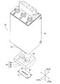
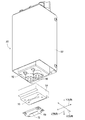
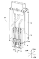
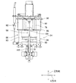
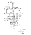
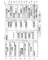
- FIG. 1 It is a perspective view of an anti-tumor aqueous solution manufacturing apparatus (atmospheric pressure plasma irradiation apparatus). It is an exploded view of a plasma generator. It is an exploded view of a plasma generator. It is sectional drawing of a plasma generator. It is a perspective view of an anti-tumor aqueous solution manufacturing apparatus. It is a side view of an anti-tumor aqueous solution manufacturing apparatus. It is a side view of an anti-tumor aqueous solution manufacturing apparatus. It is a perspective view of an anti-tumor aqueous solution manufacturing apparatus. It is the schematic of a cooling device. It is a block diagram of a control apparatus.
- the antitumor aqueous solution production apparatus of the present invention is an apparatus for producing an antitumor aqueous solution by producing an antitumor component in a raw material solution by irradiating the raw material solution with plasma.
- the antitumor aqueous solution production apparatus of the present embodiment is realized by the atmospheric pressure plasma irradiation apparatus 10 described below that performs plasma irradiation under atmospheric pressure.
- the atmospheric pressure plasma irradiation device 10 is controlled by a control device (see FIG. 10) 38.
- the control device 38 performs control based on various control data acquired by the information acquisition device (see FIG. 10) 176, and converts all or part of the control data used therein into manufacturing data and stores it. It memorize
- the control data is not particularly limited as long as it can be acquired when the antitumor aqueous solution is produced. For example, the thing regarding a raw material solution and the thing regarding the plasma to irradiate are mentioned.
- Specific examples include the temperature and composition of the atmospheric gas at the time of plasma irradiation, the flow rate and composition of the processing gas that is actually converted to plasma, the amount of raw material solution, pH, hydrogen peroxide concentration, specific component concentration, and temperature.
- the action and effect of the anti-tumor aqueous solution produced varies depending on the fluctuation of the plasma irradiation conditions to the raw material solution.
- the production data obtained is related to the anti-tumor aqueous solution produced.
- the method of associating is not particularly limited, but an identification code or the like is attached to the manufactured anti-tumor aqueous solution in advance, and manufacturing data is stored together with the identification code. Examples include a method of printing on a container of an antitumor aqueous solution.
- control data required for manufacturing an anti-tumor aqueous solution with the desired effect is prepared as time-dependent manufacturing conditions (including those that are always the same), and control obtained during actual manufacturing It is desirable to perform control so that the difference does not deviate from the allowable range compared to the data. And it can have the judgment apparatus (refer FIG. 10) 177 which judges whether it was out of the allowable range. When the determination device 177 determines that the antitumor solution is out of the allowable range, the manufactured anti-tumor aqueous solution may not be used because it is not appropriate.
- the antitumor aqueous solution production apparatus of this embodiment with medical chart data managed in a hospital or the like.
- the communication apparatus (see FIG. 10) 179 allows the electronic medical chart apparatus A to be used. Connect and exchange manufacturing data.
- the manufactured anti-tumor aqueous solution can be administered to a living body as it is and can act on a tumor present in the living body.
- a method in which a tumor is exposed by a surgical technique can be employed.
- a tumor that has not been completely removed can be killed by contact with washing when the tumor is surgically removed.
- the raw material solution is an aqueous solution in which the raw material of the antitumor aqueous solution is dissolved.
- aqueous solution in which the raw material of the antitumor aqueous solution is dissolved.
- disodium hydrogen phosphate Na 2 HPO 4
- sodium bicarbonate NaHCO 3
- L-glutamine L-Glutamine
- L-histidine L-tyrosine disodium
- L It is preferably an aqueous solution in which a solute containing at least one of -Tyrosine ⁇ 2Na) is added to water as a raw material and dissolved.
- An antitumor aqueous solution having a high effect can be obtained by performing plasma irradiation on the raw material solution using this aqueous solution.
- the raw material solution is preferably a biological fluid or a culture solution of biological cells.
- FIG. 1 shows an atmospheric pressure plasma irradiation apparatus 10 according to an embodiment of the present invention.
- the atmospheric pressure plasma irradiation apparatus 10 is an apparatus for irradiating a culture solution as a raw material solution with plasma under atmospheric pressure.
- the culture solution is held in a stationary state in the petri dish 110.
- the atmospheric pressure plasma irradiation apparatus 10 includes a plasma generator 20, a cover housing 22, an opening / closing mechanism 24, a stage 26 as a holding unit for holding the raw material solution in the petri dish 110, an elevating device 28, a cooling device (see FIG. 9) 30, Purge gas supply mechanism (see FIG. 5) 32, oxygen concentration detection mechanism 34, hydrogen peroxide concentration detection mechanism (see FIG. 10) 35, ambient gas temperature / composition detection mechanism (see FIG. 10) 37, process gas flow rate / composition Detection mechanism (see FIG. 10) 39, raw material solution amount detection mechanism (see FIG. 10) 41, raw material solution pH / specific component concentration / temperature detection mechanism (see FIG. 10) 42, plasma temperature detection mechanism (see FIG.
- the width direction of the atmospheric pressure plasma irradiation apparatus 10 is the X direction
- the depth direction of the atmospheric pressure plasma irradiation apparatus 10 is the Y direction
- the direction perpendicular to the X direction and the Y direction, that is, the vertical direction is the Z direction.
- the plasma generator 20 includes a cover 50, an upper block 52, a lower block 54, a pair of electrodes 56, and a nozzle block 58, as shown in FIGS.
- the cover 50 generally has a covered rectangular tube shape, and an upper block 52 is disposed inside the cover 50.
- the upper block 52 has a generally rectangular parallelepiped shape and is formed of ceramic.
- a pair of columnar cylindrical recesses 60 are formed on the lower surface of the upper block 52.
- the lower block 54 also has a generally rectangular parallelepiped shape and is formed of ceramic.
- a recess 62 is formed on the upper surface of the lower block 54, and the recess 62 is constituted by a pair of cylindrical column recesses 66 and a connecting recess 68 that connects the pair of column recesses 66. .
- the lower block 54 is fixed to the lower surface of the upper block 52 in a state of protruding from the lower end of the cover 50, and the cylindrical recess 60 of the upper block 52 and the cylindrical recess 66 of the lower block 54 communicate with each other. .
- the cylindrical recess 60 and the cylindrical recess 66 have substantially the same diameter.
- a slit 70 penetrating the lower surface of the lower block 54 is formed on the bottom surface of the recess 62.
- Each of the pair of electrodes 56 is disposed in a cylindrical space defined by a cylindrical recess 60 of the upper block 52 and a cylindrical recess 66 of the lower block 54. Note that the outer diameter of the electrode 56 is smaller than the inner diameter of the cylindrical recesses 60 and 66.
- the nozzle block 58 has a generally flat plate shape and is fixed to the lower surface of the lower block 54.
- the nozzle block 58 is formed with a jet port 72 that communicates with the slit 70 of the lower block 54, and the jet port 72 penetrates the nozzle block 58 in the vertical direction.
- the plasma generator 20 further has a processing gas supply device 74 (see FIG. 10).
- the processing gas supply device 74 supplies a processing gas having a predetermined composition obtained by mixing an active gas such as oxygen / hydrogen and an inert gas such as argon / nitrogen at an arbitrary ratio at a predetermined flow rate.
- the device is connected to a columnar space defined by the cylindrical recesses 60 and 66 and an upper portion of the connection recess 68 via a pipe (not shown). Thereby, the processing gas is supplied into the recess 62 from the gap between the electrode 56 and the cylindrical recess 66 and the upper portion of the connection recess 68.
- the plasma generator 20 ejects plasma from the ejection port 72 of the nozzle block 58.
- the processing gas is supplied into the recess 62 by the processing gas supply device 74.
- a voltage is applied to the pair of electrodes 56, and a current flows between the pair of electrodes 56.
- a discharge is generated between the pair of electrodes 56, and the processing gas is turned into plasma by the discharge.
- the plasma is ejected from the ejection port 72 through the slit 70.
- the cover housing 22 includes an upper cover 76 and a lower cover 78, and divides the plasma generation space inside.
- the upper cover 76 has a generally covered cylindrical shape, and a through hole (not shown) having a shape corresponding to the lower block 54 of the plasma generator 20 is formed in the lid portion of the upper cover 76.
- the cover 50 of the plasma generator 20 is being fixed in the state stood by the cover part of the upper cover 76 so that the through-hole may be covered.
- the lower block 54 and the nozzle block 58 of the plasma generator 20 protrude toward the inside of the upper cover 76 so as to extend in the Z direction.
- the plasma generated by the plasma generator 20 is ejected from the ejection port 72 of the nozzle block 58 toward the inside of the upper cover 76 in the Z direction.
- a substantially rectangular through hole (not shown) is formed on the side surface of the upper cover 76 at three equal positions, and a transparent glass plate 80 is disposed so as to close the through hole. Yes. Thereby, the inside of the upper cover 76 can be visually recognized through the glass plate 80.
- the lower cover 78 of the cover housing 22 is generally disk-shaped, and is fixed to a housing (not shown) of a placement portion on which the atmospheric pressure plasma irradiation device 10 is placed.
- the outer diameter of the lower cover 78 is larger than the outer diameter of the upper cover 76, and an annular packing 82 having the same diameter as the upper cover 76 is disposed on the upper surface of the lower cover 78. Then, the upper cover 76 is slid downward by the opening / closing mechanism 24, so that the upper cover 76 is in close contact with the packing 82 and the inside of the cover housing 22 is sealed.
- the opening / closing mechanism 24 includes a pair of slide mechanisms 86 and an air cylinder 88, as shown in FIGS.
- Each slide mechanism 86 includes a support shaft 90 and a slider 92.
- the support shaft 90 is erected so as to extend in the Z direction on the casing of the mounting portion.
- the slider 92 has a generally cylindrical shape, and is externally fitted to the support shaft 90 so as to be slidable in the axial direction of the support shaft 90.
- the upper cover 76 is held on the slider 92 by the upper bracket 96 and the lower bracket 98. Thereby, the upper cover 76 can be slid in the Z direction, that is, in the vertical direction.
- the air cylinder 88 includes a rod 100, a piston (not shown), and a cylinder 102.
- the rod 100 is disposed so as to extend in the Z direction, and is fixed to the upper cover 76 at the upper end.
- a piston is fixed to the lower end portion of the rod 100.
- the piston is fitted inside from the upper end of the cylinder 102 and moves slidably inside the cylinder 102. Further, the cylinder 102 is fixed to the housing of the above-described mounting portion at the lower end portion, and a predetermined amount of air is sealed inside the cylinder 102.
- the air cylinder 88 functions as a damper, and the upper cover 76 is prevented from being rapidly lowered.
- the air pressure inside the cylinder 102 is a pressure that can be compressed by the weight of the integrated body that slides with the upper cover 76, that is, the upper cover 76, the plasma generator 20, the slider 92, and the like. That is, when the operator lifts the upper cover 76 and releases the upper cover 76, the upper cover 76 is lowered by its own weight. Then, the upper cover 76 is in close contact with the packing 82 of the lower cover 78, and the interior of the cover housing 22 is sealed by the upper cover 76 and the lower cover 78 as shown in FIG.
- the stage 26 is generally disc-shaped, and the petri dish 110 is placed on the upper surface of the stage 26.
- One or two hydrogen peroxide detection sensors (see FIG. 10: omitted in other drawings) 147 connected to the hydrogen peroxide concentration detection mechanism 35 are arranged so that they can be inserted into the petri dish 110.
- the outer diameter of the stage 26 is made smaller than the outer diameter of the lower cover 78.
- the stage 26 is disposed on the upper surface of the lower cover 78.
- the elevating device 28 includes a support rod 112, a rack 114, a pinion 116, and an electromagnetic motor (see FIG. 10) 117.
- the lower cover 78 is formed with a through hole (not shown) penetrating in the vertical direction, and the support rod 112 is inserted through the through hole.
- the outer diameter of the support rod 112 is smaller than the inner diameter of the through hole, and the support rod 112 is movable in the vertical direction, that is, the Z direction.
- the lower surface of the stage 26 is fixed to the upper end of the support rod 112.
- the rack 114 is fixed to the outer peripheral surface of the portion of the support rod 112 that extends downward from the lower cover 78 so as to extend in the axial direction of the support rod 112.
- the pinion 116 is meshed with the rack 114 and is rotated by driving of the electromagnetic motor 117.
- the pinion 116 is rotatably held by the housing of the placement unit. With such a structure, the pinion 116 is rotated by driving the electromagnetic motor 117, whereby the support rod 112 is moved in the Z direction, and the stage 26 is moved up and down.
- a measuring rod 118 is erected on the upper surface of the lower cover 78 next to the stage 26.
- a scale is marked on the outer peripheral surface of the measuring rod 118, and the height of the stage 26 in the Z direction, that is, the amount of elevation of the stage 26 can be visually confirmed by the scale.
- the cooling device 30 includes a cooling water channel 120, a circulation device 122, and a pipe 124.
- the cooling water passage 120 penetrates the inside of the stage 26 along the surface direction of the stage 26 in a “U” shape, and is open at two locations on the outer peripheral surface of the stage 26.
- the circulation device 122 is a device for cooling the water and circulating the cooled water.
- the circulation device 122 is connected to the cooling water channel 120 via the pipe 124. Accordingly, the cooling water flows through the stage 26, whereby the stage 26 is cooled.
- the purge gas supply mechanism (atmosphere gas control device) 32 includes four air joints (three are shown in the figure) 130 and a purge gas supply device (see FIG. 10) 132. .
- the four air joints 130 are provided at four equal positions at the upper end of the side surface of the upper cover 76, and each air joint 130 is open to the inside of the upper cover 76.
- the purge gas supply device 132 is a device that supplies an inert gas such as nitrogen, and is connected to each air joint 130 via a pipe (not shown). With such a structure, the purge gas supply mechanism 32 controls the composition of the atmospheric gas in the plasma generation space by supplying an inert gas such as argon into the upper cover 76.
- the oxygen concentration detection mechanism 34 includes an air joint 140, a pipe 142, and an oxygen detection sensor (see FIG. 10) 144.
- the lower cover 78 is formed with a through hole (not shown) that communicates the upper surface and the side surface of the lower cover 78.
- the opening 146 on the upper surface side of the lower cover 78 of the through hole is located inside the packing 82.
- an air joint 140 is connected to the opening on the side surface of the lower cover 78 of the through hole.
- the oxygen detection sensor 144 is a sensor that detects an oxygen concentration, and is connected to the air joint 140 via a pipe 142. With such a structure, the oxygen concentration detection mechanism 34 detects the oxygen concentration inside the cover housing 22 when the cover housing 22 is sealed.
- the exhaust mechanism 36 includes an L-shaped pipe 150, a connecting pipe 152, and a main pipe 154.
- the lower cover 78 is formed with a duct port 160 that opens to the upper surface and the lower surface.
- the opening on the upper surface side of the lower cover 78 of the duct port 160 is a tapered surface 162 whose inner diameter increases toward the upper side. That is, when the cover housing 22 is sealed, the tapered surface 162 is inclined toward the inner wall surface of the upper cover 76.
- an L-shaped pipe 150 is connected to the opening on the lower surface side of the lower cover 78 of the duct port 160.
- a main pipe 154 is connected to the L-shaped pipe 150 via a connecting pipe 152.
- an ozone filter 166 is disposed inside the main pipe 154.
- the ozone filter 166 is made of activated carbon and adsorbs ozone.
- the temperature / composition detection mechanism 37 of the atmospheric gas is composed of a temperature sensor and an atmospheric gas sensor employed according to the type of gas contained in the atmospheric gas.
- an inert gas such as argon
- the gas mixed as an impurity is air if the purity of the argon gas used is sufficiently high. Therefore, it is assumed that air corresponding to the oxygen concentration obtained by measuring the oxygen concentration by adopting an oxygen detection sensor that measures the concentration of oxygen that is easy to detect among gases contained in the air is mixed.
- the composition of is calculated.
- the oxygen concentration detection mechanism 34 described above can be used for detection.
- the processing gas flow rate / composition detection mechanism 39 is a mechanism for detecting the flow rate and composition of the processing gas supplied from the processing gas supply device 74 up to, for example, the plasma generator 20.
- the flow rate is detected using a flow meter
- the composition of the processing gas is detected using a sensor (for example, an oxygen detection sensor) that can detect the gas contained in the processing gas.
- the amount detection mechanism 41 of the raw material solution is a mechanism that detects the amount of the raw material solution, and can detect the amount by measuring the mass or the liquid level of the raw material solution.
- the pH / specific component concentration / temperature detection mechanism 42 of the raw material solution is a mechanism for detecting the pH, specific component concentration, and temperature of the raw material solution. Although it does not specifically limit as a specific component, The component relevant to the effect of an antitumor aqueous solution (It can be estimated that various compounds correspond with the kind of antitumor aqueous solution.) Can be illustrated. An example of the specific component is hydrogen peroxide.
- the plasma temperature detection mechanism 43 is a mechanism for detecting the temperature of the generated plasma.
- the plasma radical concentration detection mechanism 44 is a mechanism for detecting the radical concentration in the generated plasma. Since the temperature and radical concentration of plasma vary depending on the location, detection is performed by setting a specific location.
- the imaging device 45 that captures the appearance of the generated plasma images the appearance of the generated plasma. It is preferable to capture a plurality of images so that at least changes over time from the start to the end of plasma irradiation can be seen. It is preferable to image the state of the raw material solution irradiated with the plasma as well as the appearance of the plasma.
- the control device 38 includes a controller 170, a plurality of drive circuits 172, a selection device 173, a setting device 174, a storage device 175, an information acquisition device 176, a determination device 177, and a manufacturing condition storage device 178. Yes.
- the storage device 175 and the manufacturing condition storage device 178 are realized by the RAM / ROM of the controller 170.
- the plurality of drive circuits 172 are connected to the electrode 56, the processing gas supply device 74, the electromagnetic motor 117, the circulation device 122, and the purge gas supply device 132.
- the controller 170 includes a CPU, a ROM, a RAM, and the like, mainly a computer, and is connected to a plurality of drive circuits 172. Thereby, the operation of the plasma generator 20, the lifting device 28, the cooling device 30, and the purge gas supply mechanism 32 is controlled by the controller 170.
- the controller 170 has a communication device 179 that is connected to the electronic medical chart device A and exchanges information.
- the controller 170 includes an oxygen detection sensor 144, a hydrogen peroxide detection sensor 147, an ambient gas temperature / composition detection mechanism 37, a process gas flow / composition detection mechanism 39, a raw material solution amount detection mechanism 41, a raw material solution pH / A specific component concentration / temperature detection mechanism 42, a plasma temperature detection mechanism 43, a plasma radical concentration detection mechanism 44, and an imaging device 45 are connected to each other.
- Get control data such as data.
- the imaging data may be obtained as it is, or obtained after calculating the plasma emission intensity, the plasma shape, the distance from the water surface of the raw material solution, and the relative position between the housing or holding unit and the plasma generator from the imaging data. You can also
- control data comprising the power supply amount and the plasma irradiation time can be obtained, and the raw material can be obtained from the control signal used to control the lifting device 28. It is also possible to calculate how far the water surface of the solution is from the plasma generator 20 and also the relative position in the casing as one of the control data.
- One or more necessary control data selected from the acquired control data is converted into manufacturing data and stored in the storage device 175 of the controller 170. Whether it is “necessary control data” is determined for each type of antitumor aqueous solution to be produced. It is preferable to store control data that has a predetermined influence or more on the effects of the manufactured anti-tumor aqueous solution as manufacturing data. Whether or not to include the control data in the manufacturing data is determined based on whether or not the control data affects the action and effect of the anti-tumor aqueous solution manufactured during the process of manufacturing the anti-tumor aqueous solution.
- control data at that specific time can be directly used as control data, or it can be changed over time.
- the control data over time is adopted as manufacturing data for the purpose of including the change over time.
- control data over time a control data string that is a collection of control data that fluctuates over time is adopted, and whether or not the deviation of the control data is within the required fluctuation range within the predetermined time range is manufactured. It can be used as a data value.
- the manufacturing data stored in the storage device 175 is related to the anti-tumor aqueous solution to be manufactured.
- the anti-tumor aqueous solution is specified based on the identification code described above.
- This identification code is associated with the patient to which the anti-tumor aqueous solution stored in the electronic medical chart apparatus A connected via the communication device 179 is applied, thereby associating the patient information with the manufactured anti-tumor aqueous solution information. Will be.
- the storage device 175 stores comparison data used when the determination device 177 makes a determination.
- Data for comparison can be set in advance by experiments or the like. The manufacturing conditions are appropriate for each type of antitumor aqueous solution to be manufactured.
- comparison data control data that cannot be guaranteed for the action and effect of the manufactured anti-tumor aqueous solution out of a predetermined range out of various control data acquired by the information acquisition device, or required
- variation with time of control data can be illustrated.
- the setting device 174 is realized as the logic of the controller 170, and controls the atmospheric pressure plasma irradiation device 10 and the like according to the manufacturing conditions stored in the manufacturing condition storage device 178.
- the plasma generator 20 and the like are controlled so that control data corresponding to target control data (or target control data string) defined in the manufacturing conditions selected according to the manufactured anti-tumor aqueous solution approaches.
- the manufacturing condition an appropriate range can be adopted as the manufacturing condition for the control data that greatly affects the action and effect of the antitumor aqueous solution to be manufactured when the value of the control data varies.
- the manufacturing conditions including the change with time are used.
- Manufacturing data / comparison data can be determined by selecting the antitumor aqueous solution to be manufactured by the selection device 173. By selecting which tumor the anti-tumor aqueous solution manufactured using the selection device 173 is applied to, appropriate data (manufacturing conditions and comparison data) is determined according to the tumor.
- the selection device 173 can also select information on a living body (patient or the like) to which the manufactured anti-tumor aqueous solution is applied. By selecting a patient, comparative data that can be used to produce an antitumor aqueous solution with appropriate properties can be obtained. Although it does not specifically limit as the selection apparatus 173, The keyboard, mouse, touch panel, and some other switch which are generally used for a computer are illustrated.
- the user can set the appropriate manufacturing conditions by selecting the tumor type and patient to be applied by the selection device 173 without having to individually input and set the appropriate plasma irradiation conditions.
- An antitumor aqueous solution produced by plasma irradiation under various conditions can be produced.
- ⁇ Plasma irradiation by atmospheric pressure plasma irradiation device By irradiating the raw material solution with plasma, the raw material solution is activated and an antitumor aqueous solution is obtained.
- the plasma irradiation is controlled in accordance with the manufacturing conditions stored in the manufacturing condition storage device 178, whereby an antitumor aqueous solution that has been appropriately irradiated with plasma can be manufactured. Further, the manufacturing data stored in the storage device 175 can be used when necessary.
- the petri dish 110 in which the culture solution is stored is placed on the stage 26 and the cover housing 22 is sealed by the above-described configuration, so that plasma is applied to the culture solution under predetermined conditions. Irradiation is possible.
- a method for irradiating the culture solution with plasma under predetermined conditions will be described in detail.
- the petri dish 110 in which the culture solution is stored is placed on the stage 26.
- a sensor that acquires control data from the raw material solution such as the hydrogen peroxide detection sensor 147 is inserted into the petri dish 110.
- the stage 26 is moved up and down to an arbitrary height by the lifting device 28. This makes it possible to arbitrarily set the distance between the plasma ejection port 72 and the culture solution as the plasma irradiation object. Note that the elevation height of the stage 26 can be confirmed by the scale of the measuring rod 118.
- the upper cover 76 is lowered and the cover housing 22 is sealed. Then, an inert gas is supplied into the cover housing 22 by the purge gas supply mechanism 32. At this time, the oxygen concentration in the cover housing 22 is detected by the oxygen concentration detection mechanism 34. Then, after the detected oxygen concentration becomes equal to or less than a preset threshold value, plasma is jetted into the cover housing 22 by the plasma generator 20.
- the target and usage conditions to which the anti-tumor aqueous solution to be manufactured before plasma irradiation is started are selected by operating the selection device 173.
- the setting device 174 of the controller 170 refers to the manufacturing conditions in the manufacturing condition storage device 178 so that the control data acquired by the information acquisition device falls within the range of the manufacturing conditions.
- the generator 20 and the like are controlled.
- the inert gas is continuously supplied to the inside of the cover housing 22 even when the plasma is irradiated.
- the inert gas is supplied to the inside of the cover housing 22, whereby the air in the cover housing 22 is exhausted to the outside of the cover housing 22.
- the oxygen concentration in the cover housing 22 conditions that affect the plasma irradiation are managed. Specifically, since plasma contains active radicals, when it reacts with oxygen, it becomes ozone and the effect of plasma irradiation decreases. For this reason, by adjusting the oxygen concentration in the cover housing 22, it is possible to control the influence of the oxygen concentration on the effect of the culture solution irradiated with plasma. Moreover, it becomes possible to irradiate a culture solution with plasma under the same conditions. Thereby, the anti-tumor aqueous solution which has a fixed anti-tumor action can be manufactured efficiently.
- the distance between the plasma jet 72 and the culture solution is arbitrarily controlled if necessary. Thereby, it becomes possible to optimize the irradiation distance as the plasma irradiation condition, and an antitumor aqueous solution having a certain antitumor action can be efficiently produced.
- the plasma generator irradiates plasma from the water surface of the culture solution in the petri dish 110. Therefore, since the plasma irradiation is performed over a wide range, the processing speed is improved.
- cooling water is circulated inside the stage 26 by the cooling device 30 during plasma irradiation.
- the stage 26 it becomes possible to suppress the temperature rise of the culture solution in the petri dish 110 by the plasma irradiation and to prevent the culture solution from evaporating.
- the temperature of the cooling water it is possible to adjust the temperature of the raw material solution at the time of plasma irradiation.
- a duct port 160 is formed in the lower cover 78.
- the duct port 160 of the lower cover 78 is formed with a tapered surface 162 having a larger inner diameter toward the upper surface of the lower cover 78.
- exhaust of gas from the inside of the cover housing 22 can be promoted.
- the exhaust mechanism 36 is provided with an ozone filter 166. Accordingly, even when ozone reacts with the reaction of plasma and oxygen, it is possible to prevent the ozone from being exhausted to the outside.
- the petri dish 110 is used to hold the raw material solution, but other containers may be used. Further, the raw material solution in the container may be circulated by some technique. In the case of circulation, circulation can be performed during the plasma irradiation. By performing the circulation, it is possible to uniformly perform plasma irradiation to the culture solution.
- the antitumor aqueous solution production apparatus of the present invention can produce an antitumor aqueous solution having an appropriate effect for each applied tumor.
- Atmospheric pressure plasma irradiation device 20 Plasma generator 22: Cover housing (housing) 26: Stage (holding part) 28: Lifting device 30: Cooling device 32: Purge gas supply mechanism (atmospheric gas control device) 35: Hydrogen peroxide concentration detection mechanism 38: Control device 72: Jet port 74: Processing gas supply device 132: Purge gas supply device 144: Oxygen detection sensor 147: Hydrogen peroxide detection sensor 175: Storage device 176: Information acquisition device 177: Judgment device 178: Manufacturing condition storage device 179: Communication device A: Electronic medical record device
Landscapes
- Health & Medical Sciences (AREA)
- Engineering & Computer Science (AREA)
- Plasma & Fusion (AREA)
- Physics & Mathematics (AREA)
- Life Sciences & Earth Sciences (AREA)
- General Health & Medical Sciences (AREA)
- Veterinary Medicine (AREA)
- Medicinal Chemistry (AREA)
- Pharmacology & Pharmacy (AREA)
- Chemical & Material Sciences (AREA)
- Public Health (AREA)
- Animal Behavior & Ethology (AREA)
- Epidemiology (AREA)
- Spectroscopy & Molecular Physics (AREA)
- Inorganic Chemistry (AREA)
- Chemical Kinetics & Catalysis (AREA)
- General Chemical & Material Sciences (AREA)
- Nuclear Medicine, Radiotherapy & Molecular Imaging (AREA)
- Organic Chemistry (AREA)
- Pharmaceuticals Containing Other Organic And Inorganic Compounds (AREA)
- Plasma Technology (AREA)
- Medicines That Contain Protein Lipid Enzymes And Other Medicines (AREA)
Abstract
プラズマ照射により生成できる抗腫瘍性水溶液の効果はプラズマ照射条件により変化し、腫瘍の種類により適正なプラズマ照射条件が存在する。そこで、適正な抗腫瘍作用を備える抗腫瘍水溶液を製造できる抗腫瘍水溶液製造装置を提供することを解決すべき課題とする。上記課題を解決する本発明の抗腫瘍水溶液製造装置(10)は、抗腫瘍作用を有する抗腫瘍水溶液を製造する装置において、抗腫瘍水溶液の原料を溶解した原料溶液を保持するステージ(26)と、ステージ(26)に保持された原料溶液に照射するプラズマを発生するプラズマ発生装置(20)と、それらの装置を制御する制御データを取得する情報取得装置(176)をもちプラズマ発生装置(20)を制御する制御装置(38)とを有し、制御装置(38)は得られた制御データのうちで製造される抗腫瘍水溶液の作用効果に大きな影響を与える制御データを記憶する記憶装置(175)をもつ装置である。
Description
本発明は、腫瘍細胞を死滅させることのできる抗腫瘍水溶液の製造に適した抗腫瘍水溶液製造装置に関する。
プラズマは励起された電子の作用により電気、化学、材料、医療の各分野への種々の応用が為されている。プラズマの医療への応用としては、プラズマ照射により製造された水溶液が腫瘍の死滅効果を有するとの技術が報告されている(特許文献1)。
ところで、プラズマ照射により生成できる抗腫瘍性をもつ水溶液(以下「抗腫瘍水溶液」と称する)の効果はプラズマ照射時間などの条件により変化し、腫瘍の種類により適正なプラズマ照射条件が存在することが認められている。
従来の抗腫瘍水溶液製造装置ではプラズマ照射条件を制御することはできるものの実際に望んだ適正な条件でプラズマ照射がされたかどうかが判断できる機構をもつものは無かった。ここで抗腫瘍水溶液を医薬品として用いる場合に後に適正な条件でプラズマ照射が為されたかどうかについて保証できる機構をもつことが望まれる。
本発明は上記実情に鑑み完成したものであり、適正な抗腫瘍作用を備える抗腫瘍水溶液を製造することを可能とするために実際のプラズマ照射条件を管理可能な抗腫瘍水溶液製造装置を提供することを解決すべき課題とする。
上記課題を解決する本発明の抗腫瘍水溶液製造装置は、抗腫瘍作用を有する抗腫瘍水溶液を製造する装置であって、プラズマ発生空間を区画するハウジングと、前記抗腫瘍水溶液の原料を溶解した原料溶液を前記プラズマ発生空間内に保持する保持部と、前記プラズマ発生空間内の雰囲気ガスの組成を制御する雰囲気ガス制御装置と、前記プラズマ発生空間内に所定の組成及び流量に制御した処理ガスを噴出する処理ガス供給装置と、前記処理ガスに電力を供給して前記保持部内の前記原料溶液に照射するプラズマを前記プラズマ発生空間内に発生するプラズマ発生装置と、前記雰囲気ガス制御装置、前記処理ガス供給装置、及び前記プラズマ発生装置を制御する制御装置と、前記制御装置が有する制御データのうちの少なくとも一部を製造される抗腫瘍水溶液の情報に関連づけられた、特定時の又は経時的な製造データに変換して記憶する記憶装置とを有する。
抗腫瘍水溶液が発揮する抗腫瘍作用はプラズマ照射条件により変化する。そのために抗腫瘍水溶液を製造するにあたりプラズマ照射条件を記憶することは重要である。記憶するプラズマ照射条件は本発明の抗腫瘍水溶液製造装置が有する制御装置が利用する制御データから一部乃至全部を選択して変換して作成された製造データを記憶することにより行う。特に製造される抗腫瘍水溶液の作用(効果)との相関性、寄与度が高い制御データを採用して製造データを作成することが望ましい。
なお、特許文献2では電子部品の製造にあたってプラズマ照射を採用する装置が開示されている(特許文献2)。特許文献2の装置では電子部品に対してプラズマ照射が適正に適用されたかどうかが判定され記憶されることが開示されているのに対して、本発明の抗腫瘍水溶液製造装置では製造される抗腫瘍水溶液の効果を適正にするためにプラズマ照射条件を記憶する装置である。
本発明によれば、プラズマ照射条件に関連する製造データを記憶することにより抗腫瘍水溶液が適正に製造されたかどうかを遡って追跡することが可能になる。また、製造された抗腫瘍水溶液の作用効果と、記憶されている製造データと照らし合わせることも可能になって、プラズマ照射条件と抗腫瘍水溶液の効果との新たな知見獲得の実現も期待できる。
本発明の抗腫瘍水溶液製造装置について図面を例に挙げて以下詳細に説明を行う。本実施形態の抗腫瘍水溶液製造装置は原料溶液にプラズマ照射を行うことにより原料溶液中に抗腫瘍成分を生成して抗腫瘍水溶液を製造する装置である。本実施形態の抗腫瘍水溶液製造装置は大気圧下でプラズマ照射を行う以下に記載の大気圧プラズマ照射装置10にて実現される。
大気圧プラズマ照射装置10は制御装置(図10参照)38により制御されている。制御装置38は情報取得装置(図10参照)176により取得される種々の制御データに基づいて制御を行っており、そこで利用した制御データのうちの全部乃至一部を製造データに変換して記憶装置(図10参照)175に記憶する。制御データとしては抗腫瘍水溶液を製造する際に取得可能なものであれば特に限定しない。例えば原料溶液に関するもの、照射するプラズマに関するものが挙げられる。具体的な例としては、プラズマ照射時における雰囲気ガスの温度・組成、実際にプラズマ化させる処理ガスの流量・組成、原料溶液の量・pH・過酸化水素濃度・特定成分濃度・温度、発生したプラズマの照射時間・温度・ラジカル濃度・発光強度・電力供給量・プラズマ形状・原料溶液の水面との距離、並びに、ハウジングとプラズマ発生装置との相対位置、保持部とプラズマ発生装置との相対位置が挙げられる。
原料溶液へのプラズマ照射条件の変動により製造される抗腫瘍水溶液の作用効果も変動する。そのために必要な作用効果が発現できる抗腫瘍水溶液が得られたかどうかを検証するためにはプラズマ照射条件に関する製造データを記憶しておくことが有用である。得られた製造データは製造される抗腫瘍水溶液に関連づけられている。関連づける方法としては特に限定しないが、製造される抗腫瘍水溶液に予め識別符号などを付しておき、その識別符号と共に製造データを記憶しておく方法、抗腫瘍水溶液を製造後に識別符号などをその抗腫瘍水溶液の容器などに印字する方法などが挙げられる。
また、抗腫瘍水溶液の製造が進行しているときに、得られる制御データを利用してフィードバック制御を行っても良い。例えば望みの作用効果をもつ抗腫瘍水溶液を製造する際に必要な制御データを経時的な製造条件(ずっと同じ条件であるものも含む)として用意しておいて実際の製造の際に得られる制御データと比較して差異が許容範囲から外れないように制御を行うことが望ましい。そして許容範囲から外れたかどうか判断する判断装置(図10参照)177をもつことができる。判断装置177が許容範囲から外れたと判断した場合には製造された抗腫瘍水溶液は適正なものではないとして使用しないようにすることができる。
更に、本実施形態の抗腫瘍水溶液製造装置を病院などで管理するカルテのデータと連携させることも可能である。特にカルテのデータを電子的に管理している電子カルテ装置Aを利用している病院などで製造される抗腫瘍水溶液を利用する場合には通信装置(図10参照)179により電子カルテ装置Aに接続して製造データのやり取りを行うことができる。
製造した抗腫瘍水溶液はそのまま生体に投与して生体中に存在する腫瘍に作用させることができる。生体への投与は外科的手法により腫瘍を露出させた状態で接触させる方法が採用できる。例えば外科的に腫瘍を除去した際の洗浄などで接触させることで完全に除去しきれなかった腫瘍を死滅させることができる。
原料溶液は抗腫瘍水溶液の原料を溶解させた水溶液である。例えばリン酸水素二ナトリウム(Na2HPO4)と、炭酸水素ナトリウム(NaHCO3)と、L-グルタミン(L-Glutamine)と、L-ヒスチジン(L-Histidine)と、L-チロシン二ナトリウム(L-Tyrosine・2Na)とのうちの少なくとも1種類を含む溶質を原料として水に添加して溶解させた水溶液であることが好ましい。この水溶液を用いた原料溶液に対してプラズマ照射を行うことで高い効果をもつ抗腫瘍水溶液を得ることができる。そして原料溶液は生体体液又は生体細胞の培養液であることが好ましい。
<大気圧プラズマ発生装置の構成>
図1に、本発明の実施例の大気圧プラズマ照射装置10を示す。大気圧プラズマ照射装置10は、大気圧下でプラズマを原料溶液としての培養液に照射するための装置である。培養液はシャーレ110内に静止状態で保持される。
図1に、本発明の実施例の大気圧プラズマ照射装置10を示す。大気圧プラズマ照射装置10は、大気圧下でプラズマを原料溶液としての培養液に照射するための装置である。培養液はシャーレ110内に静止状態で保持される。
大気圧プラズマ照射装置10は、プラズマ発生装置20、カバーハウジング22、開閉機構24、シャーレ110内の原料溶液を保持する保持部としてのステージ26、昇降装置28、冷却装置(図9参照)30、パージガス供給機構(図5参照)32、酸素濃度検出機構34、過酸化水素濃度検出機構(図10参照)35、雰囲気ガスの温度・組成検出機構(図10参照)37、処理ガスの流量・組成検出機構(図10参照)39、原料溶液の量検出機構(図10参照)41、原料溶液のpH・特定成分濃度・温度検出機構(図10参照)42、プラズマの温度検出機構(図10参照)43、プラズマのラジカル濃度検出機構(図10参照)44、発生するプラズマの外観を撮影する撮像装置(図10参照)45、排気機構36、制御装置(図10参照)38を備えている。なお、大気圧プラズマ照射装置10の幅方向をX方向と、大気圧プラズマ照射装置10の奥行方向をY方向と、X方向とY方向とに直行する方向、つまり、上下方向をZ方向とする。
プラズマ発生装置20は、図2乃至図4に示すように、カバー50と、上部ブロック52と、下部ブロック54と、1対の電極56と、ノズルブロック58とを含む。カバー50は、概して、有蓋四角筒形状をなし、カバー50の内部に、上部ブロック52が配設されている。上部ブロック52は、概して直方体形状をなし、セラミックにより成形されている。上部ブロック52の下面には、1対の円柱状の円柱凹部60が形成されている。
また、下部ブロック54も、概して直方体形状をなし、セラミックにより成形されている。下部ブロック54の上面には、凹部62が形成されており、凹部62は、1対の円柱状の円柱凹部66と、それら1対の円柱凹部66を連結する連結凹部68とによって構成されている。そして、下部ブロック54が、カバー50の下端から突出した状態で、上部ブロック52の下面に固定されており、上部ブロック52の円柱凹部60と、下部ブロック54の円柱凹部66とが連通している。なお、円柱凹部60と円柱凹部66とは、略同径とされている。また、凹部62の底面には、下部ブロック54の下面に貫通するスリット70が形成されている。
1対の電極56の各々は、上部ブロック52の円柱凹部60と、下部ブロック54の円柱凹部66とによって区画される円柱状の空間に配設されている。なお、電極56の外径は、円柱凹部60,66の内径より小さい。また、ノズルブロック58は、概して平板状をなし、下部ブロック54の下面に固定されている。ノズルブロック58には、下部ブロック54のスリット70と連通する噴出口72が形成されており、その噴出口72は、ノズルブロック58を上下方向に貫通している。
プラズマ発生装置20は、さらに、処理ガス供給装置(図10参照)74を有している。処理ガス供給装置74は、酸素・水素等の活性ガスとアルゴン・窒素等の不活性ガスとを任意の割合で混合させた所定の組成をもつ処理ガスを任意の流量である所定の流量で供給する装置であり、円柱凹部60,66によって区画される円柱状の空間および、連結凹部68の上部に、配管(図示省略)を介して、連結されている。これにより、電極56と円柱凹部66との隙間、および、連結凹部68の上部から、処理ガスが、凹部62の内部に供給される。
このような構造により、プラズマ発生装置20は、ノズルブロック58の噴出口72からプラズマを噴出する。詳しくは、凹部62の内部に、処理ガス供給装置74によって処理ガスが供給される。この際、凹部62では、1対の電極56に電圧が印加されており、1対の電極56間に電流が流れる。これにより、1対の電極56間に放電が生じ、その放電により、処理ガスがプラズマ化される。そして、プラズマが、スリット70を介して、噴出口72から噴出される。
また、カバーハウジング22は、図5に示すように、上部カバー76と、下部カバー78とを含み、プラズマ発生空間を内部に区画する。上部カバー76は、概して有蓋円筒状をなし、上部カバー76の蓋部には、プラズマ発生装置20の下部ブロック54に応じた形状の貫通穴(図示省略)が形成されている。そして、その貫通穴を覆うように、プラズマ発生装置20のカバー50が、上部カバー76の蓋部に立設された状態で固定されている。このため、プラズマ発生装置20の下部ブロック54および、ノズルブロック58が、上部カバー76の内部に向かって、Z方向に延びるように、突出している。これにより、プラズマ発生装置20によって発生されたプラズマが、ノズルブロック58の噴出口72から、上部カバー76の内部に向かって、Z方向に噴出される。
また、上部カバー76の側面には、3等配の位置に、概して矩形の貫通穴(図示省略)が形成されており、その貫通穴を塞ぐように、透明なガラス板80が配設されている。これにより、ガラス板80を介して、上部カバー76の内部を視認することが可能とされている。
カバーハウジング22の下部カバー78は、概して、円板形状とされており、大気圧プラズマ照射装置10が載置される載置部の筐体(図示省略)に固定されている。下部カバー78の外径は、上部カバー76の外径より大きくされており、下部カバー78の上面には、上部カバー76と同径の円環状のパッキン82が配設されている。そして、上部カバー76が、開閉機構24によって下方にスライドされることで、上部カバー76がパッキン82に密着し、カバーハウジング22の内部が密閉された状態となる。
詳しくは、開閉機構24は、図6および図7に示すように、1対のスライド機構86とエアシリンダ88とを含む。各スライド機構86は、支持軸90とスライダ92とを含む。支持軸90は、上記載置部の筐体に、Z方向に延びるように立設されている。また、スライダ92は、概して円筒形状をなし、支持軸90の軸方向にスライド可能に、支持軸90に外嵌されている。
そして、上部カバー76が、上部ブラケット96と下部ブラケット98とによって、スライダ92に保持されている。これにより、上部カバー76は、Z方向、つまり、上下方向にスライド可能とされている。
エアシリンダ88は、ロッド100とピストン(図示省略)とシリンダ102とを含む。ロッド100は、Z方向に延びるように配設され、上端部において上部カバー76に固定されている。また、ロッド100の下端部に、ピストンが固定されている。ピストンは、シリンダ102の上端から内部に嵌合されており、シリンダ102の内部において摺動可能に移動する。また、シリンダ102は、下端部において、上記載置部の筐体に固定されており、シリンダ102内部には、所定量のエアが封入されている。
これにより、エアシリンダ88は、ダンパとして機能し、上部カバー76の急激な下降が防止される。なお、シリンダ102内部のエア圧は、上部カバー76と共にスライドする一体物、つまり、上部カバー76,プラズマ発生装置20,スライダ92等の重量により圧縮可能な圧力とされている。つまり、作業者が、上部カバー76を上昇させた状態で、上部カバー76を離すと、上部カバー76等の自重によって上部カバー76が下降する。そして、上部カバー76が、下部カバー78のパッキン82に密着し、図8に示すように、上部カバー76と下部カバー78とによって、カバーハウジング22の内部が密閉された状態となる。
また、作業者が、上部カバー76を上昇させることで、カバーハウジング22の内部が開放される。なお、上部カバー76の上面には、磁石(図1参照)106が固定されており、上部カバー76が上昇されることで、磁石106が、上記載置部の筐体に引っ付く。このように、磁石106を上記載置部の筐体に引っ付けることで、上部カバー76を上昇させた状態、つまり、カバーハウジング22が開放された状態が維持される。
ステージ26は、概して、円板形状とされており、ステージ26の上面に、シャーレ110が載置される。そして、過酸化水素濃度検出機構35に接続された1又は2の過酸化水素検出センサ(図10参照:その他の図面では記載を省略)147がシャーレ110内に挿入できるように配設されている。また、ステージ26の外径は、下部カバー78の外径より小さくされている。そして、ステージ26は、下部カバー78の上面に配設されている。
昇降装置28は、図7に示すように、支持ロッド112と、ラック114と、ピニオン116と、電磁モータ(図10参照)117とを含む。下部カバー78には、上下方向に貫通する貫通穴(図示省略)が形成されており、その貫通穴に、支持ロッド112が挿通されている。支持ロッド112の外径は、貫通穴の内径より小さくされており、支持ロッド112は、上下方向、つまり、Z方向に移動可能とされている。その支持ロッド112の上端に、ステージ26の下面が固定されている。
また、ラック114は、支持ロッド112の軸方向に延びるように、支持ロッド112の下部カバー78から下方に延び出す部分の外周面に固定されている。ピニオン116は、ラック114に噛合されており、電磁モータ117の駆動により回転する。なお、ピニオン116は、上記載置部の筐体により回転可能に保持されている。このような構造によって、電磁モータ117の駆動によりピニオン116が回転することで、支持ロッド112がZ方向に移動し、ステージ26が昇降する。なお、下部カバー78の上面には、ステージ26の隣に、計測ロッド118が立設されている。計測ロッド118の外周面には、目盛りが記されており、その目盛りによって、ステージ26のZ方向の高さ、つまり、ステージ26の昇降量を目視によって確認することが可能となっている。
冷却装置30は、図9に示すように、冷却水路120と、循環装置122と、配管124とを含む。冷却水路120は、ステージ26の面方向に沿って、内部を「コ」の字型に貫通しており、ステージ26の外周面の2箇所において開口している。また、循環装置122は、水を冷却するとともに、冷却した水を循環させる装置である。そして、循環装置122が、配管124を介して、冷却水路120に接続されている。これにより、ステージ26の内部を冷却水が流れることで、ステージ26が冷却される。
パージガス供給機構(雰囲気ガス制御装置)32は、図5に示すように、4個のエアジョイント(図では、3個図示されている)130と、パージガス供給装置(図10参照)132とを含む。4個のエアジョイント130は、上部カバー76の側面の上端部において、4等配の位置に設けられており、各エアジョイント130は、上部カバー76の内部に開口している。パージガス供給装置132は、窒素等の不活性ガスを供給する装置であり、配管(図示省略)を介して、各エアジョイント130に接続されている。このような構造により、パージガス供給機構32は、上部カバー76の内部に、アルゴンなどの不活性ガスを供給することによりプラズマ発生空間内の雰囲気ガスの組成を制御する。
酸素濃度検出機構34は、エアジョイント140と、配管142と、酸素検出センサ(図10参照)144とを含む。下部カバー78には、下部カバー78の上面と側面とを連通する貫通穴(図示省略)が形成されている。その貫通穴の下部カバー78の上面側の開口146は、パッキン82の内側に位置している。一方、貫通穴の下部カバー78の側面側の開口に、エアジョイント140が接続されている。また、酸素検出センサ144は、酸素濃度を検出するセンサであり、配管142を介して、エアジョイント140に接続されている。このような構造により、酸素濃度検出機構34は、カバーハウジング22が密閉された際に、カバーハウジング22の内部の酸素濃度を検出する。
排気機構36は、図1に示すように、L型配管150と、連結配管152と、メイン配管154とを含む。下部カバー78には、図7に示すように、上面と下面とに開口するダクト口160が形成されている。ダクト口160の下部カバー78の上面側の開口は、上方に向かうほど内径が大きくなるテーパ面162とされている。つまり、カバーハウジング22が密閉された際に、テーパ面162は、上部カバー76の内壁面に向かって傾斜した状態となる。一方、ダクト口160の下部カバー78の下面側の開口に、L型配管150が接続されている。そして、そのL型配管150に、連結配管152を介して、メイン配管154が接続されている。なお、連結配管152のL型配管150側の部分の図示は、省略されている。また、メイン配管154の内部には、オゾンフィルタ166が配設されている。オゾンフィルタ166は、活性炭により形成されており、オゾンを吸着する。
雰囲気ガスの温度・組成検出機構37は温度センサと雰囲気ガスに含まれるガスの種類に応じて採用される雰囲気ガスセンサとから構成される。雰囲気ガスとしてアルゴンなどの不活性ガスを採用する場合には使用するアルゴンガスの純度が充分に高ければ不純物として混入するガスは空気である。そのため空気中に含まれるガスのうちで検出が容易な酸素の濃度を測定する酸素検出センサを採用して酸素濃度を測定し得られた酸素濃度に応じた空気が混入しているものとして雰囲気ガスの組成を算出する。本実施形態では雰囲気ガスの組成する具体的な検出機構としては前述した酸素濃度検出機構34にて検出することで代用できる。
処理ガスの流量・組成検出機構39は処理ガス供給装置74から供給される処理ガスの流量や組成を例えばプラズマ発生装置20に至るまでの間で検出する機構である。例えば流量は流量計、処理ガスの組成は処理ガス中に含まれるガスを検出できるセンサ(例えば酸素検出センサ)を用いて検出する。
原料溶液の量検出機構41は、原料溶液の量を検出する機構であり、質量を測定することで量を検出したり、原料溶液の液面を検出することで検出したりできる。
原料溶液のpH・特定成分濃度・温度検出機構42は、原料溶液のpH、特定成分濃度、温度を検出する機構である。特定成分としては特に限定しないが、抗腫瘍水溶液の作用効果に関連する成分(抗腫瘍水溶液の種類によって種々の化合物が該当するものと推測できる)が例示できる。特定成分としては過酸化水素が例示できる。
プラズマの温度検出機構43は、発生したプラズマの温度を検出する機構である。プラズマのラジカル濃度検出機構44は、発生したプラズマ中のラジカル濃度を検出する機構である。プラズマの温度・ラジカル濃度は場所によって変化するので特定の場所を設定して検出する。
発生するプラズマの外観を撮影する撮像装置45は、発生しているプラズマの外観を撮像する。少なくともプラズマ照射が開始されてから終了するまでの経時的な変化が分かるように複数枚撮像することが好ましい。プラズマの外観と共にプラズマ照射される原料溶液の様子も撮像することが好ましい。
制御装置38は、図10に示すように、コントローラ170、複数の駆動回路172、選択装置173、設定装置174、記憶装置175、情報取得装置176、判断装置177、製造条件記憶装置178を備えている。記憶装置175及び製造条件記憶装置178はコントローラ170のRAM・ROMにより実現されている。
複数の駆動回路172は、電極56、処理ガス供給装置74、電磁モータ117、循環装置122、パージガス供給装置132に接続されている。コントローラ170は、CPU,ROM,RAM等を備え、コンピュータを主体とするものであり、複数の駆動回路172に接続されている。これにより、プラズマ発生装置20、昇降装置28、冷却装置30、パージガス供給機構32の作動が、コントローラ170によって制御される。コントローラ170は、電子カルテ装置Aに接続されて情報のやり取りを行う通信装置179をもつ。
コントローラ170には、酸素検出センサ144、過酸化水素検出センサ147、雰囲気ガスの温度・組成検出機構37、処理ガスの流量・組成検出機構39、原料溶液の量検出機構41、原料溶液のpH・特定成分濃度・温度検出機構42、プラズマの温度検出機構43、プラズマのラジカル濃度検出機構44、撮像装置45が接続されており、コントローラ170がもつ情報取得装置176がそれぞれから出力される信号、撮像データなどの制御データを取得する。なお、撮像データはそのまま取得しても良いし、撮像データから、プラズマの発光強度、プラズマ形状、原料溶液の水面との距離、ハウジング又は保持部とプラズマ発生装置との相対位置を算出した後に取得することもできる。
更にプラズマ発生装置20の電極56への電力供給量、電力供給時間に基づいて、電力供給量及びプラズマ照射時間からなる制御データを得ることができ、昇降装置28の制御に用いた制御信号から原料溶液の水面がプラズマ発生装置20からどの程度の距離にあるか、更にはケーシング内での相対位置を制御データの1つとして算出することもできる。
取得された制御データから選択された1以上の必要な制御データが製造データに変換されてコントローラ170がもつ記憶装置175に記憶される。「必要な制御データ」かどうかは製造される抗腫瘍水溶液の種類毎に判断される。製造される抗腫瘍水溶液の作用効果に所定以上の影響を与える制御データを製造データとして記憶することが好ましい。制御データを製造データに含めるか否かは、それぞれの制御データについて抗腫瘍水溶液を製造する過程中で製造される抗腫瘍水溶液の作用効果に影響を与えるかどうかで決定する。プラズマ照射を行うある特定時における制御データの値が製造された抗腫瘍水溶液の作用効果に大きな影響を与える場合には、その特定時における制御データをそのまま制御データに採用したり、経時的な変化が作用効果に影響を与える場合にはその経時的な変化も含める目的で経時的な制御データを製造データとして採用したりする。経時的な制御データとしては時間経過と共に変動する制御データの集合である制御データ列を採用したり、所定時間範囲内において制御データの偏差が必要な変動範囲内に収まっていたか否かについてを製造データの値として採用したりできる。
記憶装置175に記憶される製造データは製造される抗腫瘍水溶液に関連づけられている。抗腫瘍水溶液の特定は先述した識別符号に基づき行われる。この識別符号は通信装置179を介して接続されている電子カルテ装置Aに保存されている抗腫瘍水溶液を適用する患者と関連づけられることで患者の情報と製造される抗腫瘍水溶液の情報とが関連づけられることになる。
記憶装置175は、判断装置177が判断を行う際に用いる比較用のデータが格納してある。比較用のデータは実験などにより予め設定することができる。製造条件は製造する抗腫瘍水溶液の種類毎に適正なものが存在する。比較用のデータとしては情報取得装置により取得される種々の制御データのうち所定の範囲を外れると製造された抗腫瘍水溶液の作用効果について保証できなくなる制御データについて特定時における値、又は、必要な制御データの経時変化の変動の許容範囲(所定範囲)を示すデータが例示できる。
設定装置174はコントローラ170のロジックとして実現されており、製造条件記憶装置178に記憶された製造条件に従って大気圧プラズマ照射装置10などを制御する。例えば製造される抗腫瘍水溶液に応じて選択される製造条件に規定された目標制御データ(又は目標制御データ列)に対応する制御データが近づくようにプラズマ発生装置20などを制御する。製造条件としては制御データのうちその値が変動すると製造する抗腫瘍水溶液の作用効果に大きな影響を与える制御データについて適正な範囲を製造条件として採用することができる。制御データの適正な範囲が経時的に変化するときにはその経時的な変化を含めて製造条件とする。
製造条件・比較用のデータは、製造すべき抗腫瘍水溶液を選択装置173で選択することで決定できる。選択装置173を用いて製造される抗腫瘍水溶液がどの腫瘍に適用されるかを選択することでその腫瘍に応じて適正なデータ(製造条件、比較用のデータ)が決定される。選択装置173はその他にも製造される抗腫瘍水溶液が適用される生体(患者など)の情報を選択することもできる。患者を選択することにより適正な性状をもつ抗腫瘍水溶液を製造するために利用できる比較用のデータを得ることができる。選択装置173としては特に限定しないがコンピュータに汎用されるキーボード、マウス、タッチパネル、その他何らかのスイッチが例示される。
以上のように、使用者は選択装置173により適用対象である腫瘍の種類や患者を選択するだけで適正なプラズマ照射条件を個別に入力・設定しなくても適正な製造条件を設定し、適正な条件によりプラズマ照射されて製造された抗腫瘍水溶液を製造することができる。
<大気圧プラズマ照射装置によるプラズマ照射>
原料溶液にプラズマを照射することで、原料溶液が活性化して抗腫瘍水溶液が得られる。プラズマ照射は製造条件記憶装置178に記憶された製造条件に従い制御されることで適正にプラズマ照射が為された抗腫瘍水溶液を製造することができる。また、記憶装置175に記憶された製造データを必要なときに利用することができる。
原料溶液にプラズマを照射することで、原料溶液が活性化して抗腫瘍水溶液が得られる。プラズマ照射は製造条件記憶装置178に記憶された製造条件に従い制御されることで適正にプラズマ照射が為された抗腫瘍水溶液を製造することができる。また、記憶装置175に記憶された製造データを必要なときに利用することができる。
大気圧プラズマ照射装置10では、上述した構成により、培養液が貯留されたシャーレ110をステージ26の上に載置し、カバーハウジング22を密閉することで、所定の条件下で培養液にプラズマを照射することが可能である。以下に、所定の条件下で、培養液にプラズマを照射する手法について、詳しく説明する。
具体的には、まず、培養液が貯留されたシャーレ110をステージ26の上に載置する。シャーレ110内には過酸化水素検出センサ147などの原料溶液からの制御データを取得するセンサを挿入する。次に、昇降装置28によってステージ26を任意の高さに昇降させる。これにより、プラズマの噴出口72と、プラズマの被照射体としての培養液との間の距離を任意に設定することが可能となる。なお、ステージ26の昇降高さは、計測ロッド118の目盛りにより確認することが可能である。
次に、上部カバー76を下降させ、カバーハウジング22を密閉させる。そして、パージガス供給機構32によって、カバーハウジング22の内部に不活性ガスが供給される。この際、酸素濃度検出機構34によって、カバーハウジング22内の酸素濃度が検出される。そして、検出された酸素濃度が予め設定された閾値以下となった後に、プラズマ発生装置20によってプラズマが、カバーハウジング22の内部に噴出される。
プラズマ照射を開始する前に製造する抗腫瘍水溶液を適用する対象、使用条件を選択装置173を操作して選択する。選択された用途に基づいてコントローラ170の設定装置174は、製造条件記憶装置178内の製造条件を参照して、情報取得装置により取得される制御データがその製造条件の範囲内になるようにプラズマ発生装置20などを制御する。
なお、プラズマが照射されている際も、カバーハウジング22の内部への不活性ガスの供給は、継続して行われる。このように、カバーハウジング22の内部に不活性ガスが供給されることで、カバーハウジング22内の空気は、カバーハウジング22の外部に排気される。この際、カバーハウジング22内の酸素濃度が調整されることで、プラズマ照射に影響を及ぼす条件が管理される。詳しくは、プラズマは、活性ラジカルを含んでいるため、酸素と反応すると、オゾンとなり、プラズマ照射の効果が低下する。このため、カバーハウジング22内の酸素濃度を調整することで、プラズマ照射された培養液の効果に対する酸素濃度の影響を制御できる。また、同一条件下で培養液にプラズマを照射することが可能となる。これにより、一定の抗腫瘍作用をもつ抗腫瘍水溶液を効率的に製造できる。
また、大気圧プラズマ照射装置10では、上述したように、プラズマの噴出口72と培養液との間の距離が必要であれば任意に制御される。これにより、プラズマ照射条件としての照射距離を適正化することが可能となり、一定の抗腫瘍作用をもつ抗腫瘍水溶液を効率的に製造できる。
そして、プラズマ発生装置はシャーレ110内の培養液の水面上からプラズマを照射する。そのためにプラズマ照射が広い範囲に行われるため処理速度が向上する。
なお、プラズマ照射時において、冷却装置30によりステージ26の内部に冷却水を循環させる。これにより、ステージ26が冷却されることで、プラズマ照射によるシャーレ110内の培養液の温度上昇を抑制し、培養液の蒸発を防止することが可能となる。また、冷却水の温度を管理することで、プラズマ照射時の原料溶液の温度を調整することが可能となる。
また、下部カバー78には、ダクト口160が形成されている。このため、カバーハウジング22内への不活性ガスの供給により、カバーハウジング22内が正圧となり、カバーハウジング22内から自然排気される。また、下部カバー78のダクト口160には、下部カバー78の上面に向かうほど内径の大きいテーパ面162が形成されている。これにより、カバーハウジング22の内部からの気体の排気を促進することが可能となる。さらに、排気機構36には、オゾンフィルタ166が設けられている。これにより、プラズマと酸素とが反応し、オゾンが発生した場合であっても、オゾンの外部への排気を防止することが可能となる。
なお、本発明は、上記実施例に限定されるものではなく、当業者の知識に基づいて種々の変更、改良を施した種々の態様で実施することが可能である。具体的には、例えば、上記実施例では、原料溶液を保持するためにシャーレ110を用いたが、それ以外の容器を用いても良い。また、その容器内の原料溶液を何らかの手法により循環させても良い。循環させる場合にはプラズマ照射を行う間、循環を行うことができる。循環を行うことにより培養液へのプラズマ照射を均一に行うことが可能になる。
本発明の抗腫瘍水溶液製造装置は適用される腫瘍毎に適正な効果を有する抗腫瘍水溶液を製造することができる。
10:大気圧プラズマ照射装置
20:プラズマ発生装置
22:カバーハウジング(ハウジング)
26:ステージ(保持部)
28:昇降装置
30:冷却装置
32:パージガス供給機構(雰囲気ガス制御装置)
35:過酸化水素濃度検出機構
38:制御装置
72:噴出口
74:処理ガス供給装置
132:パージガス供給装置
144:酸素検出センサ
147:過酸化水素検出センサ
175:記憶装置
176:情報取得装置
177:判断装置
178:製造条件記憶装置
179:通信装置
A:電子カルテ装置
20:プラズマ発生装置
22:カバーハウジング(ハウジング)
26:ステージ(保持部)
28:昇降装置
30:冷却装置
32:パージガス供給機構(雰囲気ガス制御装置)
35:過酸化水素濃度検出機構
38:制御装置
72:噴出口
74:処理ガス供給装置
132:パージガス供給装置
144:酸素検出センサ
147:過酸化水素検出センサ
175:記憶装置
176:情報取得装置
177:判断装置
178:製造条件記憶装置
179:通信装置
A:電子カルテ装置
Claims (5)
- 抗腫瘍作用を有する抗腫瘍水溶液を製造する装置であって、
プラズマ発生空間を区画するハウジングと、
前記抗腫瘍水溶液の原料を溶解した原料溶液を前記プラズマ発生空間内に保持する保持部と、
前記プラズマ発生空間内の雰囲気ガスの組成を制御する雰囲気ガス制御装置と、
前記プラズマ発生空間内に所定の組成及び流量に制御した処理ガスを噴出する処理ガス供給装置と、
前記処理ガスに電力を供給して前記保持部内の前記原料溶液に照射するプラズマを前記プラズマ発生空間内に発生するプラズマ発生装置と、
前記雰囲気ガス制御装置、前記処理ガス供給装置、及び前記プラズマ発生装置を制御する制御装置と、
前記制御装置が有する制御データのうちの少なくとも一部を製造される抗腫瘍水溶液の情報に関連づけられた、特定時の又は経時的な製造データに変換して記憶する記憶装置と、
を有する、抗腫瘍水溶液製造装置。 - 前記制御装置は、前記雰囲気ガスの温度・組成、前記処理ガスの流量・組成、前記原料溶液の量・pH・過酸化水素濃度・特定成分濃度・温度、発生した前記プラズマの照射時間・温度・ラジカル濃度・発光強度・電力供給量・プラズマ形状・前記原料溶液の水面との距離、並びに、前記ハウジング及び/又は前記保持部と前記プラズマ発生装置との相対位置のうちの1つ以上の情報を前記制御データとして取得する情報取得装置をもつ、請求項1に記載の抗腫瘍水溶液製造装置。
- 前記制御装置は、前記製造される抗腫瘍水溶液の種類に応じて適正な製造条件を記憶する製造条件記憶装置をもち、前記制御データと前記製造条件とを比較して制御を行う装置である、請求項1又は2に記載の抗腫瘍水溶液製造装置。
- 前記製造条件は、経時的なデータで有り、
前記制御装置は、前記制御データと経時的に比較した差異が許容範囲から外れたかどうかを経時的に判断する判断装置をもつ、請求項3に記載の抗腫瘍水溶液製造装置。 - 前記記憶装置は、前記製造された抗腫瘍水溶液を適用する患者のカルテデータを管理する電子カルテ装置との間で前記製造データのやり取りを行う通信装置をもつ、請求項1~4の何れか1項に記載の抗腫瘍水溶液製造装置。
Priority Applications (2)
| Application Number | Priority Date | Filing Date | Title |
|---|---|---|---|
| PCT/JP2016/073794 WO2018029862A1 (ja) | 2016-08-12 | 2016-08-12 | 抗腫瘍水溶液製造装置 |
| JP2018533404A JP6973976B2 (ja) | 2016-08-12 | 2016-08-12 | 抗腫瘍水溶液製造装置 |
Applications Claiming Priority (1)
| Application Number | Priority Date | Filing Date | Title |
|---|---|---|---|
| PCT/JP2016/073794 WO2018029862A1 (ja) | 2016-08-12 | 2016-08-12 | 抗腫瘍水溶液製造装置 |
Publications (1)
| Publication Number | Publication Date |
|---|---|
| WO2018029862A1 true WO2018029862A1 (ja) | 2018-02-15 |
Family
ID=61163407
Family Applications (1)
| Application Number | Title | Priority Date | Filing Date |
|---|---|---|---|
| PCT/JP2016/073794 Ceased WO2018029862A1 (ja) | 2016-08-12 | 2016-08-12 | 抗腫瘍水溶液製造装置 |
Country Status (2)
| Country | Link |
|---|---|
| JP (1) | JP6973976B2 (ja) |
| WO (1) | WO2018029862A1 (ja) |
Cited By (1)
| Publication number | Priority date | Publication date | Assignee | Title |
|---|---|---|---|---|
| JP2020070244A (ja) * | 2018-10-29 | 2020-05-07 | 株式会社Fuji | 腹腔内洗浄溶液の製造方法 |
Citations (3)
| Publication number | Priority date | Publication date | Assignee | Title |
|---|---|---|---|---|
| WO2013128905A1 (ja) * | 2012-02-27 | 2013-09-06 | 国立大学法人名古屋大学 | 抗腫瘍水溶液および抗癌剤とそれらの製造方法 |
| JP2016003184A (ja) * | 2014-06-13 | 2016-01-12 | 国立大学法人名古屋大学 | 抗腫瘍水溶液および抗癌剤とそれらの製造方法 |
| WO2016103695A1 (ja) * | 2014-12-24 | 2016-06-30 | 国立大学法人名古屋大学 | 抗癌剤および輸液とそれらの製造方法ならびに抗癌物質 |
Family Cites Families (4)
| Publication number | Priority date | Publication date | Assignee | Title |
|---|---|---|---|---|
| JP2008187062A (ja) * | 2007-01-31 | 2008-08-14 | Hitachi High-Technologies Corp | プラズマ処理装置 |
| CN103098559B (zh) * | 2010-09-15 | 2015-03-25 | 三菱电机株式会社 | 高频电力供给装置、等离子体处理装置以及薄膜制造方法 |
| JP5395785B2 (ja) * | 2010-12-29 | 2014-01-22 | 株式会社日立製作所 | 製造記録管理システムおよび製造記録管理方法 |
| JP6481296B2 (ja) * | 2014-09-05 | 2019-03-13 | 学校法人 名城大学 | 真核細胞の増殖方法および真核細胞の生産方法 |
-
2016
- 2016-08-12 WO PCT/JP2016/073794 patent/WO2018029862A1/ja not_active Ceased
- 2016-08-12 JP JP2018533404A patent/JP6973976B2/ja active Active
Patent Citations (3)
| Publication number | Priority date | Publication date | Assignee | Title |
|---|---|---|---|---|
| WO2013128905A1 (ja) * | 2012-02-27 | 2013-09-06 | 国立大学法人名古屋大学 | 抗腫瘍水溶液および抗癌剤とそれらの製造方法 |
| JP2016003184A (ja) * | 2014-06-13 | 2016-01-12 | 国立大学法人名古屋大学 | 抗腫瘍水溶液および抗癌剤とそれらの製造方法 |
| WO2016103695A1 (ja) * | 2014-12-24 | 2016-06-30 | 国立大学法人名古屋大学 | 抗癌剤および輸液とそれらの製造方法ならびに抗癌物質 |
Non-Patent Citations (2)
| Title |
|---|
| KOSUKE SAITO ET AL: "Development of anticancer therapy using non-thermal atmospheric pressure plasma", BULLETIN OF THE RESEARCH INSTITUTE OF MEDICAL SCIENCE, vol. 2, 1 December 2014 (2014-12-01), Nihon University School of Medicine, pages 9 - 14 * |
| TSUKI NO TATEANA·YOGAN TUBE TANSAKI "DIANA", NATIONAL INSTITUTE OF TECHNOLOGY, TOKUYAMA COLLEGE, 2012, Retrieved from the Internet <URL:http://www.satcon.jp/history/prize20/pdf/20-02.pdf> * |
Cited By (2)
| Publication number | Priority date | Publication date | Assignee | Title |
|---|---|---|---|---|
| JP2020070244A (ja) * | 2018-10-29 | 2020-05-07 | 株式会社Fuji | 腹腔内洗浄溶液の製造方法 |
| JP7154524B2 (ja) | 2018-10-29 | 2022-10-18 | 株式会社Fuji | 腹腔内洗浄溶液の製造方法 |
Also Published As
| Publication number | Publication date |
|---|---|
| JP6973976B2 (ja) | 2021-12-01 |
| JPWO2018029862A1 (ja) | 2019-06-06 |
Similar Documents
| Publication | Publication Date | Title |
|---|---|---|
| JP2010154793A (ja) | Co2インキュベータ | |
| US20230182163A1 (en) | Batch coating apparatus and batch coating method | |
| KR102467406B1 (ko) | 플라즈마 처리 장치 및 이를 이용한 방법 | |
| JP6973976B2 (ja) | 抗腫瘍水溶液製造装置 | |
| JP6788677B2 (ja) | 過酸化水素水の製造方法及び殺菌対象物の殺菌方法 | |
| JP6823656B2 (ja) | 抗腫瘍水溶液製造装置 | |
| EP3048164B1 (en) | Incubator | |
| JPWO2017037775A1 (ja) | プラズマ照射装置 | |
| KR101669961B1 (ko) | 과산화수소 플라즈마 멸균 장치 | |
| WO2023161991A1 (ja) | プラズマ処理液体製造方法、およびプラズマ照射装置 | |
| US12604389B2 (en) | Plasma irradiation apparatus and plasma-treated liquid production method | |
| JP2017113259A (ja) | 滅菌システム、制御方法 | |
| CN201862003U (zh) | 过氧化氢低温等离子体灭菌机 | |
| WO2023073878A1 (ja) | プラズマ照射装置及びプラズマ処理液体製造方法 | |
| WO2023073879A1 (ja) | プラズマ照射装置及びプラズマ処理液体製造方法 | |
| US20250296111A1 (en) | Batch coating apparatus and batch coating method | |
| CN119144448B (zh) | 一种免疫细胞体外分离培养设备及方法 | |
| EP4473981A1 (en) | Culturing device and method for sterilizing culturing device | |
| JP7773620B2 (ja) | プラズマ照射装置及びプラズマ処理液体製造方法 | |
| JPWO2018190317A1 (ja) | 滅菌方法及び滅菌装置 | |
| JP2017113257A (ja) | 滅菌システム | |
| KR20250058996A (ko) | 저온 대기압 플라즈마 표면처리 장치 및 이를 이용한 표면처리 방법 | |
| CN120283740A (zh) | 一种烤烟病虫害防治设备及方法 | |
| JP2017113258A (ja) | 滅菌システム |
Legal Events
| Date | Code | Title | Description |
|---|---|---|---|
| ENP | Entry into the national phase |
Ref document number: 2018533404 Country of ref document: JP Kind code of ref document: A |
|
| 121 | Ep: the epo has been informed by wipo that ep was designated in this application |
Ref document number: 16912742 Country of ref document: EP Kind code of ref document: A1 |
|
| NENP | Non-entry into the national phase |
Ref country code: DE |
|
| 122 | Ep: pct application non-entry in european phase |
Ref document number: 16912742 Country of ref document: EP Kind code of ref document: A1 |