WO2018020720A1 - エンジン用の制御装置 - Google Patents
エンジン用の制御装置 Download PDFInfo
- Publication number
- WO2018020720A1 WO2018020720A1 PCT/JP2017/007725 JP2017007725W WO2018020720A1 WO 2018020720 A1 WO2018020720 A1 WO 2018020720A1 JP 2017007725 W JP2017007725 W JP 2017007725W WO 2018020720 A1 WO2018020720 A1 WO 2018020720A1
- Authority
- WO
- WIPO (PCT)
- Prior art keywords
- valve
- exhaust
- intake
- opening
- throttle valve
- Prior art date
- Legal status (The legal status is an assumption and is not a legal conclusion. Google has not performed a legal analysis and makes no representation as to the accuracy of the status listed.)
- Ceased
Links
Images


Classifications
-
- F—MECHANICAL ENGINEERING; LIGHTING; HEATING; WEAPONS; BLASTING
- F02—COMBUSTION ENGINES; HOT-GAS OR COMBUSTION-PRODUCT ENGINE PLANTS
- F02D—CONTROLLING COMBUSTION ENGINES
- F02D9/00—Controlling engines by throttling air or fuel-and-air induction conduits or exhaust conduits
- F02D9/02—Controlling engines by throttling air or fuel-and-air induction conduits or exhaust conduits concerning induction conduits
-
- F—MECHANICAL ENGINEERING; LIGHTING; HEATING; WEAPONS; BLASTING
- F02—COMBUSTION ENGINES; HOT-GAS OR COMBUSTION-PRODUCT ENGINE PLANTS
- F02D—CONTROLLING COMBUSTION ENGINES
- F02D13/00—Controlling the engine output power by varying inlet or exhaust valve operating characteristics, e.g. timing
- F02D13/02—Controlling the engine output power by varying inlet or exhaust valve operating characteristics, e.g. timing during engine operation
-
- F—MECHANICAL ENGINEERING; LIGHTING; HEATING; WEAPONS; BLASTING
- F02—COMBUSTION ENGINES; HOT-GAS OR COMBUSTION-PRODUCT ENGINE PLANTS
- F02D—CONTROLLING COMBUSTION ENGINES
- F02D21/00—Controlling engines characterised by their being supplied with non-airborne oxygen or other non-fuel gas
- F02D21/06—Controlling engines characterised by their being supplied with non-airborne oxygen or other non-fuel gas peculiar to engines having other non-fuel gas added to combustion air
- F02D21/08—Controlling engines characterised by their being supplied with non-airborne oxygen or other non-fuel gas peculiar to engines having other non-fuel gas added to combustion air the other gas being the exhaust gas of engine
-
- F—MECHANICAL ENGINEERING; LIGHTING; HEATING; WEAPONS; BLASTING
- F02—COMBUSTION ENGINES; HOT-GAS OR COMBUSTION-PRODUCT ENGINE PLANTS
- F02D—CONTROLLING COMBUSTION ENGINES
- F02D43/00—Conjoint electrical control of two or more functions, e.g. ignition, fuel-air mixture, recirculation, supercharging or exhaust-gas treatment
-
- F—MECHANICAL ENGINEERING; LIGHTING; HEATING; WEAPONS; BLASTING
- F02—COMBUSTION ENGINES; HOT-GAS OR COMBUSTION-PRODUCT ENGINE PLANTS
- F02D—CONTROLLING COMBUSTION ENGINES
- F02D45/00—Electrical control not provided for in groups F02D41/00 - F02D43/00
-
- F—MECHANICAL ENGINEERING; LIGHTING; HEATING; WEAPONS; BLASTING
- F02—COMBUSTION ENGINES; HOT-GAS OR COMBUSTION-PRODUCT ENGINE PLANTS
- F02M—SUPPLYING COMBUSTION ENGINES IN GENERAL WITH COMBUSTIBLE MIXTURES OR CONSTITUENTS THEREOF
- F02M26/00—Engine-pertinent apparatus for adding exhaust gases to combustion-air, main fuel or fuel-air mixture, e.g. by exhaust gas recirculation [EGR] systems
-
- F—MECHANICAL ENGINEERING; LIGHTING; HEATING; WEAPONS; BLASTING
- F02—COMBUSTION ENGINES; HOT-GAS OR COMBUSTION-PRODUCT ENGINE PLANTS
- F02P—IGNITION, OTHER THAN COMPRESSION IGNITION, FOR INTERNAL-COMBUSTION ENGINES; TESTING OF IGNITION TIMING IN COMPRESSION-IGNITION ENGINES
- F02P5/00—Advancing or retarding ignition; Control therefor
- F02P5/04—Advancing or retarding ignition; Control therefor automatically, as a function of the working conditions of the engine or vehicle or of the atmospheric conditions
- F02P5/145—Advancing or retarding ignition; Control therefor automatically, as a function of the working conditions of the engine or vehicle or of the atmospheric conditions using electrical means
- F02P5/15—Digital data processing
- F02P5/152—Digital data processing dependent on pinking
Definitions
- the present invention relates to an engine control device including an exhaust gas recirculation device that recirculates a part of exhaust gas to intake air.
- Engines equipped with an exhaust gas recirculation device that recirculates part of the exhaust gas to the intake air are widely used.
- the exhaust gas recirculation device uses a part of the exhaust gas discharged from the combustion chamber as the exhaust gas recirculation gas via the exhaust gas recirculation passage that connects the exhaust passage drawn from the combustion chamber and the intake passage leading to the combustion chamber. It is returning to the passage.
- knocking tends to occur if the amount of exhaust gas recirculation gas introduced into the intake air is small.
- knock control such as retarding the ignition timing.
- various knock controls are performed according to the driving situation.
- an air-cooled or water-cooled exhaust gas recirculation cooling device is provided to take measures to increase the amount of exhaust gas recirculation gas introduced into the intake air by cooling the exhaust gas recirculation gas.
- introduction of the cooled exhaust gas recirculation gas is also effective in improving fuel consumption.
- Japanese Patent Laid-Open No. 2011-112031 (for example, see claim 3, paragraph 0013, etc.)
- variable valve mechanism the reduction of the intake pipe pressure by the control of the variable valve mechanism may be limited depending on the operating conditions such as the high load range of the engine. For this reason, in particular, a more effective knock control technique is required depending on the driving situation such as a high load range of the engine.
- an object of the present invention is to smoothly introduce the exhaust gas recirculation gas by ensuring a sufficient intake negative pressure mainly in an engine high load region or the like.
- the present invention provides the combustion through an intake passage leading to a combustion chamber, an exhaust passage drawn out from the combustion chamber, and an exhaust recirculation passage connecting the exhaust passage and the intake passage.
- An exhaust gas recirculation device that recirculates a portion of the exhaust gas discharged from the chamber to the intake passage as exhaust recirculation gas, an intake valve that opens and closes an opening of the intake passage to the combustion chamber, and the combustion in the exhaust passage
- An exhaust valve that opens and closes an opening to the chamber, an intake and exhaust valve control means that controls opening and closing of the intake valve and the exhaust valve, and a throttle that is disposed upstream of the introduction portion of the exhaust gas recirculation gas in the intake passage
- a knock that is predicted to cause knocking when the exhaust gas recirculation gas is introduced.
- the intake / exhaust valve control means advances the valve opening timing of the intake valve from a standard timing corresponding to the operating conditions at that time, and the throttle valve control means opens the throttle valve.
- the knock prediction operation region in which the knock control is performed is a high load region of the engine.
- the throttle valve opening amount is limited to the amount that can generate the negative pressure necessary to introduce the exhaust gas recirculation gas into the intake passage downstream of the throttle valve. Further, it is possible to adopt a configuration in which the upper limit is set to an amount that can secure a predetermined intake amount corresponding to the accelerator opening.
- the advance amount of the opening timing of the intake valve is determined by the negative pressure necessary for introducing the exhaust gas recirculation gas into the intake passage downstream from the throttle valve after the throttle valve is shifted to the throttle side. It is possible to adopt a configuration that is set to a minimum amount that can generate the above.
- an ignition device that generates a spark for burning the fuel in the fuel chamber
- an ignition timing control unit that controls an ignition timing by the ignition device
- the knock control is the ignition timing control unit It is possible to employ a configuration involving the advance of the ignition timing due to.
- the present invention advances the valve opening timing of the intake valve from the standard timing corresponding to the operating conditions at that time, and Since the throttle valve opening is set to the throttle side of the standard opening corresponding to the accelerator opening at that time, by ensuring sufficient intake negative pressure mainly in the engine high load range etc.
- the exhaust gas recirculation gas can be smoothly introduced.
- FIG. 1 is an overall view showing a configuration of an engine E and a control device for the engine E according to the present invention.
- the engine E of this embodiment is a naturally aspirated gasoline engine that does not include a supercharger.
- the structure of the engine E is that an intake passage 11 that feeds intake air into the combustion chamber 3 of the cylinder 2 that houses the piston 4, an exhaust passage 12 drawn out from the combustion chamber 3, a fuel that faces the intake passage 11 or the combustion chamber 3.
- the injection valve 10 etc. are provided.
- An intake port that is an opening of the intake passage 11 to the combustion chamber 3 and an exhaust port that is an opening of the exhaust passage 12 to the combustion chamber 3 are opened and closed by an intake valve 8 and an exhaust valve 9, respectively.
- the intake passage 11 is provided with a throttle valve 16 that adjusts the flow passage area of the intake passage 11 upstream from the intake port, an air flow sensor 14 that detects the amount of intake air introduced into the combustion chamber 3, an air cleaner 13, and the like. It is done.
- an air-fuel ratio detection means 17 that detects exhaust components from the exhaust port toward the downstream side
- an exhaust purification unit 18 that includes a catalyst that removes harmful substances in the exhaust, etc., a silencer (not shown) Etc.) are provided.
- the exhaust passage 12 and the intake passage 11 are communicated with each other by an exhaust gas recirculation passage 21 that constitutes the exhaust gas recirculation device 20.
- a part of the exhaust gas discharged from the combustion chamber 3 returns to the intake passage 11 as exhaust gas recirculation gas via the exhaust gas recirculation passage 21.
- the exhaust gas recirculation gas merges with the intake air in the intake air passage 11 according to the pressure state in the intake air passage 11 when the exhaust gas recirculation valve 22 provided in the exhaust gas recirculation passage 21 is opened and closed and the throttle valve 16 is opened and closed. Yes.
- various types of cooling devices for exhaust gas recirculation gas such as an air cooling type and a water cooling type may be arranged.
- the supply of fuel and air to the engine E, the control of fuel injection timing and injection amount, the overall control of opening and closing of valves, the control of the ignition device 5, and other controls are electronic controls provided in the vehicle on which the engine E is mounted.
- the unit (Electronic Control Unit) 30 performs.
- the opening / closing control of the intake valve 8 and the exhaust valve 9 is performed by the intake / exhaust valve control means 31 provided in the electronic control unit 30.
- the throttle valve control means 32 provided in the electronic control unit 30 controls the opening / closing of the throttle valve 16
- the exhaust control provided in the electronic control unit 30 controls the introduction of exhaust gas recirculation gas into the intake air by the exhaust gas recirculation device 20. This is performed by the gas recirculation device control means 33.
- knock control for preventing the occurrence of knocking is performed in the knock prediction operation region in which the occurrence of knocking during the introduction of the exhaust gas recirculation gas is predicted.
- the knock prediction operation region is determined according to the engine E specification by the rotation speed and load of the engine E, the accelerator opening, the required torque, and other operation conditions.
- the knock control is set so as to be automatically performed when the operating state of the engine E enters the predetermined knock prediction operation region.
- the electronic control unit 30 includes knock prediction detection means 34 that detects the occurrence of knocking by means of engine vibration, sound, or other methods, or predicts the occurrence of knocking based on previously stored data. Yes.
- knock prediction detection means 34 detects the occurrence of knocking or predicts it, it is recognized that the driving state has entered the knock prediction driving region and knock control is automatically performed. Good. Since the condition for the occurrence of knocking may slightly change with the aging of the engine E, in such a case, knock control that is automatically performed when the knock prediction detection means 34 detects or predicts the occurrence of knocking is performed. It is valid. In this case, the operation state in which the knock control is performed is learned as a knock predicted operation region, and is reflected in the subsequent operation control by the electronic control unit 30.
- the knock prediction operation region where the knock control is set is set to the high load region of the engine E. However, depending on the specifications of the engine E, the knock prediction operation region where the knock control is set may be expanded to the middle load region of the engine E.
- knock control The contents of knock control are as follows.
- the intake / exhaust valve control means 31 When the operation state of the engine E enters the knock prediction operation region, the intake / exhaust valve control means 31 performs control to advance the valve opening timing of the intake valve 8 from the standard timing corresponding to the operation condition at that time.
- the standard time refers to the valve opening time of the intake valve when knock control is not performed under the operating conditions at that time.
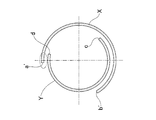
- FIG. 3A and 3B show schematic diagrams of valve timing.
- FIG. 3A is a valve timing in a normal operation in which knock control is not performed
- FIG. 3B is a valve timing in the case where knock control is performed.
- the symbol X is the opening period of the intake valve 8
- the symbol Y is the opening period of the exhaust valve 9.
- the valve opening timing of the intake valve 8 is advanced from the standard timing a in FIG. 3A to the advance timing a ′ in FIG. 3B.
- the standard time a is on the retard side from the top dead center
- the advance timing a ' is set on the further advance side from the top dead center.
- the closing timing of the intake valve 8 is also advanced by the same amount as that of the valve opening timing. Further, there is no change in the valve opening timing c and the valve closing timing d of the exhaust valve 9. For this reason, the valve overlap period is enlarged on the top dead center side and reduced on the bottom dead center side.
- the intake amount to the combustion chamber 3 can be increased by advancing the valve opening timing of the intake valve 8 when entering the knock prediction operation region. Reduction of the valve overlap period due to advance of the closing timing of the intake valve 8 also contributes to the increase of the intake amount.
- the throttle valve control means 32 sets the opening of the throttle valve 16 to the throttle side with respect to the standard opening corresponding to the accelerator opening at that time.
- the standard opening is the opening of the throttle valve 16 when knock control is not performed under the operating conditions at that time.
- the opening degree of the throttle valve 16 is determined so that the opening degree increases as the accelerator opening degree increases.
- the information on the accelerator opening is obtained by the accelerator opening sensor 6, and the information on the opening of the throttle valve 16 is obtained by the throttle position sensor 15 and used for the control of the electronic control unit 30.
- the rotation sensor 19 obtains the information on the rotational speed of the engine E and is used for control of the electronic control unit 30.
- the electronic control unit 30 can calculate the load of the engine E based on these pieces of information, and determines whether the operation state is a low load range, a medium load range, or a high load range. It can also be determined.
- the negative pressure in the intake passage 11 becomes larger.
- the amount of exhaust recirculation gas introduced into the intake passage 11 can be increased. This is because if the negative pressure in the intake passage 11 is increased, the exhaust gas recirculation gas is easily introduced into the intake air. For this reason, for example, when the accelerator is depressed to some extent, normally, control that increases the opening of the throttle valve 16 corresponding to the depression should be performed. It also occurs when control is performed to reduce the opening of 16.
- the engine E includes an ignition device (ignition plug) 5 that generates a spark for burning the fuel in the fuel chamber 3, and the electronic control unit 30 controls the ignition timing by the ignition device 5. Means 35 are provided.
- the ignition timing control means 35 advances the ignition timing. This is because the ignition timing can be advanced by increasing the ratio of the exhaust gas recirculation gas to the intake air, and the fuel consumption is improved by the advance of the ignition timing.
- the advance amount of the opening timing of the intake valve 8 generates a negative pressure necessary to introduce a predetermined exhaust gas recirculation gas corresponding to the operating state after the throttle valve 16 is shifted to the throttle side.
- the advance timing of the ignition timing is set so as to be performed until the time when the fuel consumption becomes the highest, that is, the time when the numerical value of the travelable distance per unit amount of fuel becomes the minimum.
- the throttle opening of the throttle valve 16 corresponds to the accelerator opening with the lower limit being the amount that can generate the negative pressure required to introduce the exhaust gas recirculation gas into the intake passage 11 downstream of the throttle valve 16.
- the predetermined amount of intake air is set within a range having an upper limit that can be secured.
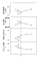
- the opening degree of the throttle valve 16 is reduced as indicated by the arrow P in the graph of FIG. 2, the ratio of the exhaust gas recirculation gas in the intake air increases as indicated by the arrow Q.
- the ignition timing can be advanced as shown by the arrow R.
- the advance of the ignition timing is performed until the fuel efficiency becomes the highest (best).
- the opening timing of the intake valve 8 that is set to the most retarded angle (the most retarded timing that cannot be further retarded) in the middle load region of the engine E is severely knocked, that is, knocking is not performed.
- the intake negative pressure is secured by advancing more than the normal setting in the high load range where it is likely to occur, and the amount of exhaust gas recirculation gas introduced is increased. By increasing the exhaust gas recirculation gas, it becomes possible to advance the ignition timing, so that the fuel consumption can be improved.
- the valve opening period of the intake valve 8 near the top dead center surrounded by the chain line in FIG. 3B becomes longer and the intake amount into the combustion chamber increases. If it is too much, the intake amount will increase too much, and conversely, knocking is likely to occur. For this reason, the advance angle of the opening timing of the intake valve 8 is sufficient by the minimum advance amount that can generate a negative pressure sufficient to introduce the exhaust gas recirculation gas by the throttle opening of the throttle valve 16.
- This minimum advance amount is set as the lower limit advance amount, the advance amount at which knocking starts to occur due to excessive intake, is set as the upper limit advance amount, and within the range of the lower limit advance amount and the upper limit advance amount, It is desirable to set the amount of advancement that provides fuel efficiency.
- the lower limit advance amount and the upper limit advance amount can be used for controlling information obtained in advance by experiments or the like in the electronic control unit 30.
- the present invention has been described by comparing the middle load region and the high load region of the engine E.
- the opening timing of the intake valve 8 is set to be the same as that in the middle load range in the high load range. For this reason, for example, when the opening timing of the conventional intake valve 8 is 9 ° after the top dead center in both the medium load range and the high load range, in the present invention, the high load is maintained as it is in the medium load range. In the region knock control, for example, it can be set to 1 ° before top dead center.
- the amount of exhaust gas recirculation gas introduced into the intake air may be zero, so in such a case, knock control is not performed and in a high load range. Even if it exists, it is desirable that the throttle opening be a standard opening corresponding to the accelerator opening.
- the change in volumetric efficiency when the intake valve 8 opens is similar to the behavior of the fuel consumption rate in the graph of FIG.
- the ignition timing starts to retard from the vicinity where the valve opening timing exceeds 0 ° before the top dead center due to the advance angle of the valve opening timing of the intake valve 8. This is because the increase in volumetric efficiency accompanying the advancement of the opening timing of the intake valve 8 and the rise in temperature in the cylinder due to the increase in exhaust gas drawn back into the combustion chamber 3 from the exhaust passage 12 side introduce the exhaust recirculation gas.
- the engine E of this embodiment is a gasoline engine (spark ignition engine) that does not include a supercharger, but the present invention can also be applied to an engine E that includes a supercharger such as a turbocharger.
Landscapes
- Engineering & Computer Science (AREA)
- Chemical & Material Sciences (AREA)
- Combustion & Propulsion (AREA)
- Mechanical Engineering (AREA)
- General Engineering & Computer Science (AREA)
- Signal Processing (AREA)
- Combined Controls Of Internal Combustion Engines (AREA)
- Output Control And Ontrol Of Special Type Engine (AREA)
- Electrical Control Of Ignition Timing (AREA)
- Exhaust-Gas Circulating Devices (AREA)
- Control Of Throttle Valves Provided In The Intake System Or In The Exhaust System (AREA)
Abstract
燃焼室(3)へ通じる吸気通路(11)及び排気通路(12)と、排気ガスの一部を排気還流ガスとして吸気通路(11)に還流する排気ガス再循環装置(20)と、吸気バルブ(8)及び排気バルブ(9)の開閉を制御する吸排気バルブ制御手段(31)と、吸気通路(11)に配置されるスロットルバルブ(16)と、スロットルバルブ(16)の開閉を制御するスロットルバルブ制御手段(32)とを備え、排気還流ガスの導入時におけるノッキングの発生が予測されるノック予測運転領域において、吸気バルブ(8)の開弁時期をその時点での運転条件に対応する標準時期よりも進角させ、且つ、スロットルバルブ(16)の開度をその時点でのアクセル開度に対応する標準開度よりも絞り側に設定することにより、排気還流ガスの吸気通路(11)への導入量を増大させるノック制御を行うエンジン用の制御装置とした。
Description
この発明は、排気ガスの一部を吸気に還流する排気ガス再循環装置を備えたエンジン用の制御装置に関する。
排気ガスの一部を吸気に還流する排気ガス再循環装置を備えたエンジンが広く採用されている。排気ガス再循環装置は、燃焼室から引き出された排気通路と燃焼室へ通じる吸気通路とを結ぶ排気還流通路を介して、燃焼室から排出される排気ガスの一部を、排気還流ガスとして吸気通路に還流している。
排気ガス再循環装置を備えたエンジンでは、吸気への排気還流ガスの導入量が少ないと、ノッキングを発生させやすい。ノッキングの発生を防止するためには、例えば、ガソリンエンジンでは、点火時期を遅角させる等のノック制御を行うことで、ある程度の対応が可能である。また、ディーゼルエンジンにおいても、運転状況に応じた種々のノック制御を行っている。
しかし、高圧縮比エンジンでは、通常のエンジンよりも相対的にノッキングを生じやすいという傾向がある。このため、空冷式や水冷式の排気還流ガス用冷却装置を配置し、排気還流ガスを冷却することにより、吸気への排気還流ガスの導入量を増やす対策を行っている。このように、冷却された排気還流ガスを導入することは、燃費の向上にも効果がある。
しかし、エンジンの高負荷域では、吸気負圧が不足することから、充分な量の排気還流ガスを吸気に導入できない場合があるという問題がある。
なお、例えば、下記特許文献1では、排気還流ガスの流量低下が発生している場合に、スロットルバルブより下流の吸気通路内の圧力が低下するように、可変動弁機構を制御している。可変動弁機構によって、吸気バルブの閉弁タイミングを進角させたり、又は、バルブオーバーラップを減少させたりすることによって、吸気通路内の圧力、すなわち吸気管圧力を低下させ、排気還流ガスの導入量増加を図っている。
しかし、可変動弁機構の制御による吸気管圧力の低減は、例えば、エンジンの高負荷域等、運転状況によっては制限される場合もある。このため、特に、エンジンの高負荷域等、運転状況によっては、さらに効果的なノック制御の手法が求められる。
そこで、この発明の課題は、主としてエンジンの高負荷域等において、充分な吸気負圧を確保することにより、排気還流ガスを円滑に導入することである。
上記の課題を解決するために、この発明は、燃焼室へ通じる吸気通路と、前記燃焼室から引き出された排気通路と、前記排気通路と前記吸気通路とを結ぶ排気還流通路を介して前記燃焼室から排出される排気ガスの一部を排気還流ガスとして吸気通路に還流する排気ガス再循環装置と、前記吸気通路の前記燃焼室への開口を開閉する吸気バルブと、前記排気通路の前記燃焼室への開口を開閉する排気バルブと、前記吸気バルブ及び前記排気バルブの開閉を制御する吸排気バルブ制御手段と、前記吸気通路における前記排気還流ガスの導入部よりも上流側に配置されるスロットルバルブと、前記スロットルバルブの開閉を制御するスロットルバルブ制御手段とを備え、前記排気還流ガスの導入時におけるノッキングの発生が予測されるノック予測運転領域において、前記吸排気バルブ制御手段は前記吸気バルブの開弁時期をその時点での運転条件に対応する標準時期よりも進角させ、且つ、前記スロットルバルブ制御手段は前記スロットルバルブの開度をその時点でのアクセル開度に対応する標準開度よりも絞り側に設定することにより、前記排気還流ガスの前記吸気通路への導入量を増大させるノック制御を行うエンジン用の制御装置を採用した。
ここで、前記ノック制御を行う前記ノック予測運転領域はエンジンの高負荷域である構成を採用することができる。
また、これらの各態様において、前記スロットルバルブの開度の絞り量は、前記スロットルバルブより下流の前記吸気通路に前記排気還流ガスを導入するのに必要な負圧を発生しうる量を下限とし、前記アクセル開度に対応する所定の吸気量の確保が可能な量を上限とする範囲内で設定される構成を採用することができる。
さらに、前記吸気バルブの開弁時期の進角量は、前記スロットルバルブの絞り側への移行後において、前記スロットルバルブより下流の前記吸気通路に前記排気還流ガスを導入するのに必要な負圧を発生しうる最低限の量に設定される構成を採用することができる。
これらの各態様において、前記燃料室内の燃料を燃焼させるための火花を生じさせる点火装置と、前記点火装置による点火時期を制御する点火時期制御手段とを備え、前記ノック制御は前記点火時期制御手段による点火時期の進角を伴う構成を採用することができる。
このとき、前記点火時期の進角は燃費が最高となる時期まで行うことが望ましい。
この発明は、排気還流ガスの導入時におけるノッキングの発生が予測されるノック予測運転領域において、吸気バルブの開弁時期をその時点での運転条件に対応する標準時期よりも進角させ、且つ、スロットルバルブの開度をその時点でのアクセル開度に対応する標準開度よりも絞り側に設定するようにしたので、主としてエンジンの高負荷域等において、充分な吸気負圧を確保することにより、排気還流ガスを円滑に導入することができる。
この発明の実施形態を、図面に基づいて説明する。図1は、この発明のエンジンE及びエンジンE用の制御装置の構成を示す全体図である。この実施形態のエンジンEは、過給機を備えない自然吸気式のガソリンエンジンである。
エンジンEの構成は、ピストン4を収容したシリンダ2の燃焼室3内に吸気を送り込む吸気通路11、燃焼室3から引き出された排気通路12、吸気通路11内に又は燃焼室3内に臨む燃料噴射弁10等を備えている。吸気通路11の燃焼室3への開口である吸気ポート、及び、排気通路12の燃焼室3への開口である排気ポートは、それぞれ吸気バルブ8、排気バルブ9によって開閉される。
吸気通路11には、吸気ポートから上流側に向かって、吸気通路11の流路面積を調節するスロットルバルブ16、燃焼室3へ導入される吸気量を検出するエアフローセンサ14,エアクリーナ13等が設けられる。
排気通路12には、排気ポートから下流側に向かって、排気の成分を検出する空燃比検出手段17、排気中の有害物を除去する触媒等を備えた排気浄化部18、消音器(図示せず)等が設けられる。
また、排気通路12と吸気通路11との間は、排気ガス再循環装置20を構成する排気還流通路21によって連通している。排気還流通路21を介して、燃焼室3から排出される排気ガスの一部が、排気還流ガスとして吸気通路11に還流する。排気還流通路21に設けられた排気還流弁22の開閉とスロットルバルブ16の開閉に伴う吸気通路11内の圧力状態に応じて、排気還流ガスが吸気通路11内の吸気に合流するようになっている。
なお、排気還流通路21の途中に、空冷式、水冷式等、種々の方式の排気還流ガス用冷却装置を配置してもよい。
このエンジンEへの燃料や空気の供給、燃料の噴射時期及び噴射量の制御、バルブ類の開閉の制御全般、点火装置5の制御、その他の制御は、エンジンEを搭載する車両が備える電子制御ユニット(Electronic Control Unit)30が行っている。
また、特に、吸気バルブ8、排気バルブ9の開閉の制御は、電子制御ユニット30が備える吸排気バルブ制御手段31によって行われる。さらに、スロットルバルブ16の開閉の制御は、電子制御ユニット30が備えるスロットルバルブ制御手段32が、排気ガス再循環装置20による排気還流ガスの吸気への導入の制御は、電子制御ユニット30が備える排気ガス再循環装置制御手段33によって行われる。
この発明のエンジンE用の制御装置では、排気還流ガスの導入時におけるノッキングの発生が予測されるノック予測運転領域において、ノッキングの発生を防止するためのノック制御が行われる。ノック予測運転領域は、エンジンEの仕様に応じて、そのエンジンEの回転数や負荷、アクセル開度、要求トルク、その他運転条件によって定められる。ノック制御は、エンジンEの運転状態が、その定められたノック予測運転領域に入った際に、自動的に行われるように設定されている。
なお、電子制御ユニット30は、ノッキングの発生を、エンジンの振動や音やその他方法により検知する、あるいは、ノッキングの発生を、予め記憶されたデータに基づいて予測するノック予測検知手段34を備えている。
このため、ノック予測検知手段34がノッキングの発生を検知した場合、あるいは、予測した場合に、運転状態がノック予測運転領域に入ったと認識してノック制御を自動的に行うように設定してもよい。ノッキングが発生する条件は、エンジンEの経年とともに多少変化する場合があるので、このような場合には、ノック予測検知手段34がノッキングの発生を検知又は予測した場合に自動的に行うノック制御が有効である。この場合、そのノック制御が行われた運転状態が、ノック予測運転領域として学習され、電子制御ユニット30により以降の運転制御に反映される。
ノック制御が設定されるノック予測運転領域は、エンジンEの高負荷域に設定される。ただし、エンジンEの仕様によっては、ノック制御が設定されるノック予測運転領域を、エンジンEの中負荷域にまで拡大してもよい。
ノック制御の内容は、次のようになっている。
エンジンEの運転状態がノック予測運転領域に入ると、吸排気バルブ制御手段31は、吸気バルブ8の開弁時期をその時点での運転条件に対応する標準時期よりも進角させる制御を行う。ここで、標準時期とは、その時点での運転条件において、ノック制御を行わないとした場合の吸気バルブの開弁時期をいう。
図3A、図3Bに、バルブタイミングの模式図を示す。図3Aは、ノック制御を行わない通常の運転におけるバルブタイミング、図3Bは、ノック制御を行う場合におけるバルブタイミングである。図中の符号Xが吸気バルブ8の開弁期間、符号Yが排気バルブ9の開弁期間である。吸気バルブ8の開弁時期は、図3Aの標準時期aから、図3Bの進角時期a’へと進角されている。ここでは、標準時期aが上死点から遅角側であったのに対し、進角時期a’は上死点からさらに進角側に設定されている。
なお、吸気バルブ8の閉弁時期も、開弁時期の進角量と同じ量だけ進角されている。また、排気バルブ9の開弁時期c、閉弁時期dに変更はない。このため、バルブオーバーラップの期間は上死点側では拡大されており、下死点側では縮小されている。
このように、ノック予測運転領域に入った際に、吸気バルブ8の開弁時期を進角させることにより、燃焼室3への吸気量を増大させることができる。吸気バルブ8の閉弁時期が進角することによるバルブオーバーラップの期間の縮小も、この吸気量の増大に寄与している。
これにより、スロットルバルブ16の開度をその時点でのアクセル開度に対応する標準開度よりも絞り側に設定することができる。すなわち、吸気バルブ8の開弁時期の進角により吸気量が増大するため、スロットルバルブ16の開弁量を小さくしても、所定の吸気量の確保が可能だからである。
したがって、ノック制御では、スロットルバルブ制御手段32は、スロットルバルブ16の開度をその時点でのアクセル開度に対応する標準開度よりも絞り側に設定する。ここで、標準開度とは、その時点での運転条件において、ノック制御を行わないとした場合のスロットルバルブ16の開度である。ノック制御を行わない通常の運転では、スロットルバルブ16の開度は、アクセル開度が大きいほどその開度が大きくなるように決定される。
ここで、アクセルの開度は、アクセル開度センサ6がその情報を取得し、スロットルバルブ16の開度は、スロットルポジションセンサ15がその情報を取得し、電子制御ユニット30の制御に用いられる。また、エンジンEの回転数の情報は、回転センサ19がその情報を取得し、電子制御ユニット30の制御に用いられる。電子制御ユニット30は、これらの情報に基づいてエンジンEの負荷を算出することができ、また、運転状態が、低負荷域であるか、中負荷域であるか、高負荷域であるかを判別することもできる。
スロットルバルブ16の開度を絞ることにより、吸気通路11内の負圧はより大きなものとなる。吸気負圧の確保により、排気還流ガスの吸気通路11への導入量を増大させることができる。吸気通路11内の負圧が高まれば、排気還流ガスを吸気に導入させやすいからである。このため、例えば、アクセルをある程度踏み込んだ際に、通常であれば、その踏み込みに対応してスロットルバルブ16の開度が大きくなる制御が行われるべきところ、ノック制御下では、逆に、スロットルバルブ16の開度が小さくなる制御が行われる場合も発生する。
また、このエンジンEでは、燃料室3内の燃料を燃焼させるための火花を生じさせる点火装置(点火プラグ)5を備え、電子制御ユニット30は、点火装置5による点火時期を制御する点火時期制御手段35を備えている。
ノック制御では、点火時期制御手段35による点火時期の進角が行われる。これは、吸気に占める排気還流ガスの比率が増大することにより点火時期の進角が可能となり、その点火時期の進角により、燃費を改善しようとするものである。
ここで、吸気バルブ8の開弁時期の進角量は、スロットルバルブ16の絞り側への移行後において、運転状態に応じた所定の排気還流ガスを導入するのに必要な負圧を発生しうる最低限の量に設定される。また、点火時期の進角は、燃費が最高となる時期、すなわち、燃料の単位量当たりの走行可能距離の数値が最小となる時期まで行うように設定される。
また、スロットルバルブ16の開度の絞り量は、スロットルバルブ16より下流の吸気通路11に、排気還流ガスを導入するのに必要な負圧を発生しうる量を下限とし、アクセル開度に対応する所定の吸気量の確保が可能な量を上限とする範囲内で設定される。
例えば、図2のグラフの矢印Pのように、スロットルバルブ16の開度を絞ると、矢印Qのように、吸気中の排気還流ガスの比率が増加する。これにより、矢印Rのように、点火時期を進角することができる。点火時期の進角は、矢印Sのように、燃費が最高(最良)となる時期まで行われる。
この一連のノック制御により、例えば、エンジンEの中負荷域では最遅角設定(それ以上遅角できない最遅の時期)としている吸気バルブ8の開弁時期を、ノックが厳しい、すなわち、ノッキングが発生しやすい高負荷域では通常の設定よりも進角させることにより吸気負圧を確保し、排気還流ガスの導入量を増加させる。排気還流ガスの増加により、点火時期の進角が可能となるので燃費の改善が実現できる。
ここで、吸気バルブ8の開弁時期の進角により、図3B中に鎖線で囲む上死点付近での吸気バルブ8の開弁期間が長くなり燃焼室への吸入量が増えるが、進角し過ぎると吸気量が増えすぎて、逆にノッキングが発生しやすい状態となってしまう。このため、吸気バルブ8の開弁時期の進角は、スロットルバルブ16の開度の絞りにより、排気還流ガスを導入できるだけの負圧を発生しうる最低限の進角量で充分である。この最低限の進角量を下限進角量とし、吸気の入り過ぎによりノッキングが発生し始める進角量を上限進角量とし、下限進角量と上限進角量の範囲内で、最高の燃費となる進角量に設定することが望ましい。下限進角量と上限進角量は、予め実験等によって得られた情報を電子制御ユニット30に記憶させて、その制御に用いることができる。
なお、この実施形態では、図2のように、エンジンEの中負荷域と高負荷域との比較によりこの発明を説明したが、今回の発明を適用しない従来のエンジンE用の制御装置では、吸気バルブ8の開弁時期は、高負荷域は中負荷域と同じ設定とされている場合が多かった。このため、例えば、従来の吸気バルブ8の開弁時期が、中負荷域及び高負荷域の両方において、上死点後9°としていたところ、この発明では、中負荷域ではそのままで、高負荷域のノック制御では、例えば、上死点前1°と設定することができる。
ただし、アクセル開度を全開にするような加速状況では、吸気への排気還流ガスの導入量をゼロとする場合があるので、このような場合には、ノック制御は行わず、高負荷域であってもスロットル開度はアクセル開度に応じた標準開度とすることが望ましい。
ノック制御時において、吸気バルブ8の開弁時期の進角時の体積効率の変化挙動は、図2のグラフ中における燃料消費率の挙動に類似する。ここで、図2のグラフにおいて、吸気バルブ8の開弁時期の進角により、その開弁時期が上死点前0゜付近を超える付近から、点火時期が遅角し始めている。これは、吸気バルブ8の開弁時期の進角に伴う体積効率の向上と、排気通路12側から燃焼室3内に引き戻される排気ガスの増加による筒内の温度上昇が、排気還流ガスの導入量増大による筒内温度の低下効果を上回ることと、エンジンEの出力を保つためには、スロットバルブ16の開度を絞るにも限界があり、また、排気還流ガスの導入量を増大させるにも限界があることによるものと考えられる。
この実施形態のエンジンEは、過給機を備えないガソリンエンジン(火花点火式エンジン)としたが、ターボチャージャー等の過給機を備えたエンジンEにおいても、この発明を適用できる。
1 エンジン本体
2 シリンダ
3 燃焼室
4 ピストン
5 点火装置
6 アクセル開度センサ
8 吸気バルブ
9 排気バルブ
10 燃料噴射弁(インジェクタ)
11 吸気通路
12 排気通路
13 エアクリーナ
14 エアフローセンサ
15 スロットルポジションセンサ
16 スロットルバルブ
17 空燃比検出手段
18 排気浄化部
19 回転センサ
20 排気ガス再循環装置
21 排気還流通路
22 排気還流弁
30 電子制御ユニット
31 吸排気バルブ制御手段
32 スロットルバルブ制御手段
33 排気ガス再循環装置制御手段
34 ノック予測検知手段
35 点火時期制御手段
2 シリンダ
3 燃焼室
4 ピストン
5 点火装置
6 アクセル開度センサ
8 吸気バルブ
9 排気バルブ
10 燃料噴射弁(インジェクタ)
11 吸気通路
12 排気通路
13 エアクリーナ
14 エアフローセンサ
15 スロットルポジションセンサ
16 スロットルバルブ
17 空燃比検出手段
18 排気浄化部
19 回転センサ
20 排気ガス再循環装置
21 排気還流通路
22 排気還流弁
30 電子制御ユニット
31 吸排気バルブ制御手段
32 スロットルバルブ制御手段
33 排気ガス再循環装置制御手段
34 ノック予測検知手段
35 点火時期制御手段
Claims (6)
- 燃焼室へ通じる吸気通路と、
前記燃焼室から引き出された排気通路と、
前記排気通路と前記吸気通路とを結ぶ排気還流通路を介して前記燃焼室から排出される排気ガスの一部を排気還流ガスとして吸気通路に還流する排気ガス再循環装置と、
前記吸気通路の前記燃焼室への開口を開閉する吸気バルブと、
前記排気通路の前記燃焼室への開口を開閉する排気バルブと、
前記吸気バルブ及び前記排気バルブの開閉を制御する吸排気バルブ制御手段と、
前記吸気通路における前記排気還流ガスの導入部よりも上流側に配置されるスロットルバルブと、
前記スロットルバルブの開閉を制御するスロットルバルブ制御手段と、
を備え、
前記排気還流ガスの導入時におけるノッキングの発生が予測されるノック予測運転領域において、前記吸排気バルブ制御手段は前記吸気バルブの開弁時期をその時点での運転条件に対応する標準時期よりも進角させ、且つ、前記スロットルバルブ制御手段は前記スロットルバルブの開度をその時点でのアクセル開度に対応する標準開度よりも絞り側に設定することにより、前記排気還流ガスの前記吸気通路への導入量を増大させるノック制御を行う
エンジン用の制御装置。 - 前記ノック制御を行う前記ノック予測運転領域はエンジンの高負荷域である
請求項1に記載のエンジン用の制御装置。 - 前記スロットルバルブの開度の絞り量は、前記スロットルバルブより下流の前記吸気通路に前記排気還流ガスを導入するのに必要な負圧を発生しうる量を下限とし、前記アクセル開度に対応する所定の吸気量の確保が可能な量を上限とする範囲内で設定される
請求項1又は2に記載のエンジン用の制御装置。 - 前記吸気バルブの開弁時期の進角量は、前記スロットルバルブの絞り側への移行後において、前記スロットルバルブより下流の前記吸気通路に前記排気還流ガスを導入するのに必要な負圧を発生しうる最低限の量に設定される
請求項3に記載のエンジン用の制御装置。 - 前記燃料室内の燃料を燃焼させるための火花を生じさせる点火装置と、
前記点火装置による点火時期を制御する点火時期制御手段と、
を備え、
前記ノック制御は前記点火時期制御手段による点火時期の進角を伴う
請求項1~4の何れか1項に記載のエンジン用の制御装置。 - 前記点火時期の進角は燃費が最高となる時期まで行う
請求項5に記載のエンジン用の制御装置。
Applications Claiming Priority (2)
| Application Number | Priority Date | Filing Date | Title |
|---|---|---|---|
| JP2016147288A JP6766500B2 (ja) | 2016-07-27 | 2016-07-27 | エンジンの制御装置 |
| JP2016-147288 | 2016-07-27 |
Publications (1)
| Publication Number | Publication Date |
|---|---|
| WO2018020720A1 true WO2018020720A1 (ja) | 2018-02-01 |
Family
ID=61017365
Family Applications (1)
| Application Number | Title | Priority Date | Filing Date |
|---|---|---|---|
| PCT/JP2017/007725 Ceased WO2018020720A1 (ja) | 2016-07-27 | 2017-02-28 | エンジン用の制御装置 |
Country Status (2)
| Country | Link |
|---|---|
| JP (1) | JP6766500B2 (ja) |
| WO (1) | WO2018020720A1 (ja) |
Citations (5)
| Publication number | Priority date | Publication date | Assignee | Title |
|---|---|---|---|---|
| JPH04175449A (ja) * | 1990-11-06 | 1992-06-23 | Mazda Motor Corp | エンジンの排ガス還流装置 |
| JPH0586945A (ja) * | 1991-09-26 | 1993-04-06 | Mazda Motor Corp | 火花点火式エンジン |
| JP2003293863A (ja) * | 2002-04-04 | 2003-10-15 | Toyota Motor Corp | 内燃機関の制御装置 |
| JP2003328839A (ja) * | 2002-05-09 | 2003-11-19 | Toyota Motor Corp | 内燃機関における排気環流の制御 |
| JP2012136960A (ja) * | 2010-12-24 | 2012-07-19 | Daihatsu Motor Co Ltd | 内燃機関の制御装置 |
-
2016
- 2016-07-27 JP JP2016147288A patent/JP6766500B2/ja active Active
-
2017
- 2017-02-28 WO PCT/JP2017/007725 patent/WO2018020720A1/ja not_active Ceased
Patent Citations (5)
| Publication number | Priority date | Publication date | Assignee | Title |
|---|---|---|---|---|
| JPH04175449A (ja) * | 1990-11-06 | 1992-06-23 | Mazda Motor Corp | エンジンの排ガス還流装置 |
| JPH0586945A (ja) * | 1991-09-26 | 1993-04-06 | Mazda Motor Corp | 火花点火式エンジン |
| JP2003293863A (ja) * | 2002-04-04 | 2003-10-15 | Toyota Motor Corp | 内燃機関の制御装置 |
| JP2003328839A (ja) * | 2002-05-09 | 2003-11-19 | Toyota Motor Corp | 内燃機関における排気環流の制御 |
| JP2012136960A (ja) * | 2010-12-24 | 2012-07-19 | Daihatsu Motor Co Ltd | 内燃機関の制御装置 |
Also Published As
| Publication number | Publication date |
|---|---|
| JP2018017162A (ja) | 2018-02-01 |
| JP6766500B2 (ja) | 2020-10-14 |
Similar Documents
| Publication | Publication Date | Title |
|---|---|---|
| CN104712420B (zh) | 涡轮增压器的控制方法 | |
| CN101268268B (zh) | 内燃机的增压压力控制装置及增压压力控制方法 | |
| CN101688494B (zh) | 用于内燃发动机的控制设备 | |
| JP6848888B2 (ja) | 強ノックの抑制が可能なエンジン | |
| CN101171411A (zh) | 内燃机用控制系统 | |
| JP2013185536A (ja) | 内燃機関の制御装置 | |
| JP4196343B2 (ja) | 内燃機関およびその運転方法 | |
| JP2017007516A (ja) | 制御装置 | |
| CN107923358A (zh) | 发动机控制装置 | |
| JP2008303744A (ja) | 内燃機関の制御装置 | |
| JP2009216035A (ja) | 内燃機関の制御装置 | |
| JP6766500B2 (ja) | エンジンの制御装置 | |
| JP2008280915A (ja) | 内燃機関の吸排気弁制御装置 | |
| JP5948897B2 (ja) | 内燃機関 | |
| JP6432548B2 (ja) | エンジンの制御装置 | |
| JP2017008724A (ja) | 内燃機関の制御装置及びスロットル弁保護装置 | |
| JP6554863B2 (ja) | エンジンの制御装置 | |
| JP2007085199A (ja) | 内燃機関のアイドル回転制御装置 | |
| JP7256682B2 (ja) | 内燃機関の制御方法及び内燃機関の制御装置 | |
| JP5594265B2 (ja) | エンジンの吸気制御装置 | |
| WO2018051609A1 (ja) | ターボチャージャー付きエンジンおよびターボチャージャー付きエンジンの運転方法 | |
| JP2012255385A (ja) | 内燃機関の制御装置 | |
| JP2011122466A (ja) | 内燃機関のノック抑制方法 | |
| JP2010230044A (ja) | 過給機付き内燃機関の制御装置 | |
| JP2019167926A (ja) | エンジンの制御装置 |
Legal Events
| Date | Code | Title | Description |
|---|---|---|---|
| 121 | Ep: the epo has been informed by wipo that ep was designated in this application |
Ref document number: 17833731 Country of ref document: EP Kind code of ref document: A1 |
|
| NENP | Non-entry into the national phase |
Ref country code: DE |
|
| 122 | Ep: pct application non-entry in european phase |
Ref document number: 17833731 Country of ref document: EP Kind code of ref document: A1 |