WO2018020564A1 - レーザシステム - Google Patents
レーザシステム Download PDFInfo
- Publication number
- WO2018020564A1 WO2018020564A1 PCT/JP2016/071803 JP2016071803W WO2018020564A1 WO 2018020564 A1 WO2018020564 A1 WO 2018020564A1 JP 2016071803 W JP2016071803 W JP 2016071803W WO 2018020564 A1 WO2018020564 A1 WO 2018020564A1
- Authority
- WO
- WIPO (PCT)
- Prior art keywords
- light
- optical path
- laser
- ops
- amplifier
- Prior art date
- Legal status (The legal status is an assumption and is not a legal conclusion. Google has not performed a legal analysis and makes no representation as to the accuracy of the status listed.)
- Ceased
Links
Images









Classifications
-
- G—PHYSICS
- G03—PHOTOGRAPHY; CINEMATOGRAPHY; ANALOGOUS TECHNIQUES USING WAVES OTHER THAN OPTICAL WAVES; ELECTROGRAPHY; HOLOGRAPHY
- G03F—PHOTOMECHANICAL PRODUCTION OF TEXTURED OR PATTERNED SURFACES, e.g. FOR PRINTING, FOR PROCESSING OF SEMICONDUCTOR DEVICES; MATERIALS THEREFOR; ORIGINALS THEREFOR; APPARATUS SPECIALLY ADAPTED THEREFOR
- G03F7/00—Photomechanical, e.g. photolithographic, production of textured or patterned surfaces, e.g. printing surfaces; Materials therefor, e.g. comprising photoresists; Apparatus specially adapted therefor
- G03F7/70—Microphotolithographic exposure; Apparatus therefor
- G03F7/70008—Production of exposure light, i.e. light sources
- G03F7/70025—Production of exposure light, i.e. light sources by lasers
-
- G—PHYSICS
- G03—PHOTOGRAPHY; CINEMATOGRAPHY; ANALOGOUS TECHNIQUES USING WAVES OTHER THAN OPTICAL WAVES; ELECTROGRAPHY; HOLOGRAPHY
- G03F—PHOTOMECHANICAL PRODUCTION OF TEXTURED OR PATTERNED SURFACES, e.g. FOR PRINTING, FOR PROCESSING OF SEMICONDUCTOR DEVICES; MATERIALS THEREFOR; ORIGINALS THEREFOR; APPARATUS SPECIALLY ADAPTED THEREFOR
- G03F7/00—Photomechanical, e.g. photolithographic, production of textured or patterned surfaces, e.g. printing surfaces; Materials therefor, e.g. comprising photoresists; Apparatus specially adapted therefor
- G03F7/70—Microphotolithographic exposure; Apparatus therefor
- G03F7/70008—Production of exposure light, i.e. light sources
- G03F7/70041—Production of exposure light, i.e. light sources by pulsed sources, e.g. multiplexing, pulse duration, interval control or intensity control
-
- G—PHYSICS
- G03—PHOTOGRAPHY; CINEMATOGRAPHY; ANALOGOUS TECHNIQUES USING WAVES OTHER THAN OPTICAL WAVES; ELECTROGRAPHY; HOLOGRAPHY
- G03F—PHOTOMECHANICAL PRODUCTION OF TEXTURED OR PATTERNED SURFACES, e.g. FOR PRINTING, FOR PROCESSING OF SEMICONDUCTOR DEVICES; MATERIALS THEREFOR; ORIGINALS THEREFOR; APPARATUS SPECIALLY ADAPTED THEREFOR
- G03F7/00—Photomechanical, e.g. photolithographic, production of textured or patterned surfaces, e.g. printing surfaces; Materials therefor, e.g. comprising photoresists; Apparatus specially adapted therefor
- G03F7/70—Microphotolithographic exposure; Apparatus therefor
- G03F7/70483—Information management; Active and passive control; Testing; Wafer monitoring, e.g. pattern monitoring
- G03F7/7055—Exposure light control in all parts of the microlithographic apparatus, e.g. pulse length control or light interruption
- G03F7/70575—Wavelength control, e.g. control of bandwidth, multiple wavelength, selection of wavelength or matching of optical components to wavelength
-
- H—ELECTRICITY
- H01—ELECTRIC ELEMENTS
- H01S—DEVICES USING THE PROCESS OF LIGHT AMPLIFICATION BY STIMULATED EMISSION OF RADIATION [LASER] TO AMPLIFY OR GENERATE LIGHT; DEVICES USING STIMULATED EMISSION OF ELECTROMAGNETIC RADIATION IN WAVE RANGES OTHER THAN OPTICAL
- H01S3/00—Lasers, i.e. devices using stimulated emission of electromagnetic radiation in the infrared, visible or ultraviolet wave range
- H01S3/005—Optical devices external to the laser cavity, specially adapted for lasers, e.g. for homogenisation of the beam or for manipulating laser pulses, e.g. pulse shaping
- H01S3/0057—Temporal shaping, e.g. pulse compression, frequency chirping
-
- H—ELECTRICITY
- H01—ELECTRIC ELEMENTS
- H01S—DEVICES USING THE PROCESS OF LIGHT AMPLIFICATION BY STIMULATED EMISSION OF RADIATION [LASER] TO AMPLIFY OR GENERATE LIGHT; DEVICES USING STIMULATED EMISSION OF ELECTROMAGNETIC RADIATION IN WAVE RANGES OTHER THAN OPTICAL
- H01S3/00—Lasers, i.e. devices using stimulated emission of electromagnetic radiation in the infrared, visible or ultraviolet wave range
- H01S3/09—Processes or apparatus for excitation, e.g. pumping
- H01S3/091—Processes or apparatus for excitation, e.g. pumping using optical pumping
- H01S3/094—Processes or apparatus for excitation, e.g. pumping using optical pumping by coherent light
- H01S3/094076—Pulsed or modulated pumping
-
- H—ELECTRICITY
- H01—ELECTRIC ELEMENTS
- H01S—DEVICES USING THE PROCESS OF LIGHT AMPLIFICATION BY STIMULATED EMISSION OF RADIATION [LASER] TO AMPLIFY OR GENERATE LIGHT; DEVICES USING STIMULATED EMISSION OF ELECTROMAGNETIC RADIATION IN WAVE RANGES OTHER THAN OPTICAL
- H01S3/00—Lasers, i.e. devices using stimulated emission of electromagnetic radiation in the infrared, visible or ultraviolet wave range
- H01S3/09—Processes or apparatus for excitation, e.g. pumping
- H01S3/091—Processes or apparatus for excitation, e.g. pumping using optical pumping
- H01S3/094—Processes or apparatus for excitation, e.g. pumping using optical pumping by coherent light
- H01S3/094088—Processes or apparatus for excitation, e.g. pumping using optical pumping by coherent light with ASE light recycling, i.e. with reinjection of the ASE light, e.g. by reflectors or circulators
-
- H—ELECTRICITY
- H01—ELECTRIC ELEMENTS
- H01S—DEVICES USING THE PROCESS OF LIGHT AMPLIFICATION BY STIMULATED EMISSION OF RADIATION [LASER] TO AMPLIFY OR GENERATE LIGHT; DEVICES USING STIMULATED EMISSION OF ELECTROMAGNETIC RADIATION IN WAVE RANGES OTHER THAN OPTICAL
- H01S3/00—Lasers, i.e. devices using stimulated emission of electromagnetic radiation in the infrared, visible or ultraviolet wave range
- H01S3/23—Arrangements of two or more lasers not provided for in groups H01S3/02 - H01S3/22, e.g. tandem arrangements of separate active media
- H01S3/2366—Arrangements of two or more lasers not provided for in groups H01S3/02 - H01S3/22, e.g. tandem arrangements of separate active media comprising a gas as the active medium
-
- G—PHYSICS
- G03—PHOTOGRAPHY; CINEMATOGRAPHY; ANALOGOUS TECHNIQUES USING WAVES OTHER THAN OPTICAL WAVES; ELECTROGRAPHY; HOLOGRAPHY
- G03F—PHOTOMECHANICAL PRODUCTION OF TEXTURED OR PATTERNED SURFACES, e.g. FOR PRINTING, FOR PROCESSING OF SEMICONDUCTOR DEVICES; MATERIALS THEREFOR; ORIGINALS THEREFOR; APPARATUS SPECIALLY ADAPTED THEREFOR
- G03F7/00—Photomechanical, e.g. photolithographic, production of textured or patterned surfaces, e.g. printing surfaces; Materials therefor, e.g. comprising photoresists; Apparatus specially adapted therefor
- G03F7/70—Microphotolithographic exposure; Apparatus therefor
- G03F7/70483—Information management; Active and passive control; Testing; Wafer monitoring, e.g. pattern monitoring
- G03F7/7055—Exposure light control in all parts of the microlithographic apparatus, e.g. pulse length control or light interruption
-
- H—ELECTRICITY
- H01—ELECTRIC ELEMENTS
- H01S—DEVICES USING THE PROCESS OF LIGHT AMPLIFICATION BY STIMULATED EMISSION OF RADIATION [LASER] TO AMPLIFY OR GENERATE LIGHT; DEVICES USING STIMULATED EMISSION OF ELECTROMAGNETIC RADIATION IN WAVE RANGES OTHER THAN OPTICAL
- H01S3/00—Lasers, i.e. devices using stimulated emission of electromagnetic radiation in the infrared, visible or ultraviolet wave range
- H01S3/005—Optical devices external to the laser cavity, specially adapted for lasers, e.g. for homogenisation of the beam or for manipulating laser pulses, e.g. pulse shaping
-
- H—ELECTRICITY
- H01—ELECTRIC ELEMENTS
- H01S—DEVICES USING THE PROCESS OF LIGHT AMPLIFICATION BY STIMULATED EMISSION OF RADIATION [LASER] TO AMPLIFY OR GENERATE LIGHT; DEVICES USING STIMULATED EMISSION OF ELECTROMAGNETIC RADIATION IN WAVE RANGES OTHER THAN OPTICAL
- H01S3/00—Lasers, i.e. devices using stimulated emission of electromagnetic radiation in the infrared, visible or ultraviolet wave range
- H01S3/005—Optical devices external to the laser cavity, specially adapted for lasers, e.g. for homogenisation of the beam or for manipulating laser pulses, e.g. pulse shaping
- H01S3/0071—Beam steering, e.g. whereby a mirror outside the cavity is present to change the beam direction
-
- H—ELECTRICITY
- H01—ELECTRIC ELEMENTS
- H01S—DEVICES USING THE PROCESS OF LIGHT AMPLIFICATION BY STIMULATED EMISSION OF RADIATION [LASER] TO AMPLIFY OR GENERATE LIGHT; DEVICES USING STIMULATED EMISSION OF ELECTROMAGNETIC RADIATION IN WAVE RANGES OTHER THAN OPTICAL
- H01S3/00—Lasers, i.e. devices using stimulated emission of electromagnetic radiation in the infrared, visible or ultraviolet wave range
- H01S3/14—Lasers, i.e. devices using stimulated emission of electromagnetic radiation in the infrared, visible or ultraviolet wave range characterised by the material used as the active medium
- H01S3/22—Gases
- H01S3/223—Gases the active gas being polyatomic, i.e. containing two or more atoms
- H01S3/225—Gases the active gas being polyatomic, i.e. containing two or more atoms comprising an excimer or exciplex
- H01S3/2251—ArF, i.e. argon fluoride is comprised for lasing around 193 nm
-
- H—ELECTRICITY
- H01—ELECTRIC ELEMENTS
- H01S—DEVICES USING THE PROCESS OF LIGHT AMPLIFICATION BY STIMULATED EMISSION OF RADIATION [LASER] TO AMPLIFY OR GENERATE LIGHT; DEVICES USING STIMULATED EMISSION OF ELECTROMAGNETIC RADIATION IN WAVE RANGES OTHER THAN OPTICAL
- H01S3/00—Lasers, i.e. devices using stimulated emission of electromagnetic radiation in the infrared, visible or ultraviolet wave range
- H01S3/23—Arrangements of two or more lasers not provided for in groups H01S3/02 - H01S3/22, e.g. tandem arrangements of separate active media
- H01S3/2308—Amplifier arrangements, e.g. MOPA
- H01S3/2325—Multi-pass amplifiers, e.g. regenerative amplifiers
-
- H—ELECTRICITY
- H01—ELECTRIC ELEMENTS
- H01S—DEVICES USING THE PROCESS OF LIGHT AMPLIFICATION BY STIMULATED EMISSION OF RADIATION [LASER] TO AMPLIFY OR GENERATE LIGHT; DEVICES USING STIMULATED EMISSION OF ELECTROMAGNETIC RADIATION IN WAVE RANGES OTHER THAN OPTICAL
- H01S3/00—Lasers, i.e. devices using stimulated emission of electromagnetic radiation in the infrared, visible or ultraviolet wave range
- H01S3/23—Arrangements of two or more lasers not provided for in groups H01S3/02 - H01S3/22, e.g. tandem arrangements of separate active media
- H01S3/2308—Amplifier arrangements, e.g. MOPA
- H01S3/2325—Multi-pass amplifiers, e.g. regenerative amplifiers
- H01S3/2333—Double-pass amplifiers
-
- H—ELECTRICITY
- H01—ELECTRIC ELEMENTS
- H01S—DEVICES USING THE PROCESS OF LIGHT AMPLIFICATION BY STIMULATED EMISSION OF RADIATION [LASER] TO AMPLIFY OR GENERATE LIGHT; DEVICES USING STIMULATED EMISSION OF ELECTROMAGNETIC RADIATION IN WAVE RANGES OTHER THAN OPTICAL
- H01S3/00—Lasers, i.e. devices using stimulated emission of electromagnetic radiation in the infrared, visible or ultraviolet wave range
- H01S3/23—Arrangements of two or more lasers not provided for in groups H01S3/02 - H01S3/22, e.g. tandem arrangements of separate active media
- H01S3/2375—Hybrid lasers
Definitions
- the present disclosure relates to a laser system including a laser device and an optical pulse stretcher.
- the semiconductor exposure apparatus As semiconductor integrated circuits are miniaturized and highly integrated, improvement in resolving power is demanded in semiconductor exposure apparatuses.
- the semiconductor exposure apparatus is simply referred to as “exposure apparatus”. For this reason, the wavelength of light output from the light source for exposure is being shortened.
- a gas laser device As a light source for exposure, a gas laser device is used instead of a conventional mercury lamp.
- a KrF excimer laser device that outputs ultraviolet light with a wavelength of 248 nm and an ArF excimer laser device that outputs ultraviolet light with a wavelength of 193.4 nm are used as the exposure laser device.
- Current exposure technology includes immersion exposure that fills the gap between the projection lens on the exposure apparatus side and the wafer with liquid and changes the refractive index of the gap to shorten the apparent wavelength of the exposure light source.
- immersion exposure is performed using an ArF excimer laser device as an exposure light source, the wafer is irradiated with ultraviolet light having a wavelength of 134 nm in water. This technique is called ArF immersion exposure.
- ArF immersion exposure is also called ArF immersion lithography.
- the spectral line width in natural oscillation of KrF and ArF excimer laser devices is as wide as about 350 to 400 pm, the chromatic aberration of laser light (ultraviolet light) projected on the wafer by the projection lens on the exposure device side is generated, resulting in high resolution. descend. Therefore, it is necessary to narrow the spectral line width of the laser light output from the gas laser device until the chromatic aberration becomes negligible. For this reason, a narrowband module (Line Narrowing Module) having a narrowband element is provided in the laser resonator of the gas laser device. With this narrowband module, the spectral linewidth is narrowed.
- the band narrowing element may be an etalon or a grating.
- a laser device whose spectral line width is narrowed in this way is called a narrow-band laser device.
- an optical pulse stretcher that extends the pulse width of the laser beam is used for the laser device so that damage to the optical system of the exposure apparatus is reduced.
- the optical pulse stretcher lowers the peak power level of each pulsed light by decomposing each pulsed light included in the laser light output from the laser device into a plurality of pulsed lights having a time difference.
- JP 2011-176358 A Japanese Patent No. 2760159 JP-A-11-312631 JP 2012-156531 A
- a laser system comprises: A. A laser device for outputting a pulsed laser beam; and B. A first optical pulse stretcher including a delayed optical path for extending the pulse width of a pulsed laser beam, wherein the beam waist position of the circulating light output by circulating around the delayed optical path is determined in the direction of the optical path axis according to the number of rotations.
- a first optical pulse stretcher configured to change to
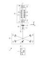
- FIG. 1 is a diagram schematically showing a configuration of a laser system according to a comparative example.
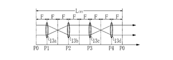
- FIG. 2 is a diagram for explaining the positional relationship between the beam splitter and the first to fourth concave mirrors.
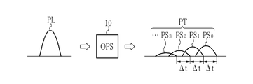
- FIG. 3 is a diagram for explaining output light from the OPS.
- FIG. 4 is a diagram showing a configuration of an OPS that decomposes pulsed laser light temporally and spatially.
- FIG. 5 is a diagram for explaining an incident optical path of the extended pulse laser beam into the discharge space.
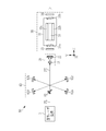
- FIG. 6 is a diagram illustrating a configuration of the laser system according to the first embodiment.
- FIG. 7 is a diagram for explaining the positional relationship between the beam splitter and the first to fourth concave mirrors.
- FIG. 8 is a diagram for explaining the extended pulse laser beam incident on the amplifier.
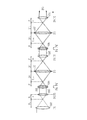
- FIG. 9A is a diagram for explaining zero-round light output from the OPS.
- FIG. 9B is a diagram illustrating one-round light output from the OPS.
- FIG. 9C is a diagram illustrating the two-round light output from the OPS.
- FIG. 10 is a diagram for explaining an incident optical path of the extended pulse laser beam into the discharge space.
- FIG. 11A is a schematic diagram illustrating a method for measuring a change in the beam waist position of output light from the OPS according to the first embodiment.
- FIG. 11A is a schematic diagram illustrating a method for measuring a change in the beam waist position of output light from the OPS according to the first embodiment.
- FIG. 11B is a diagram illustrating a measurement example of a change in the beam waist position of the output light from the OPS of the comparative example.
- FIG. 12 is a diagram illustrating a change in the spot diameter of output light from the OPS.
- FIG. 13 is a diagram illustrating a configuration of the OPS according to the first modification.
- FIG. 14 is a diagram illustrating a configuration of the OPS according to the second modification.
- FIG. 15 is a diagram illustrating the configuration of the OPS used in the laser system according to the second embodiment.
- FIG. 16A is a diagram for describing zero-round light output from the OPS.
- FIG. 16B is a diagram illustrating one-round light output from the OPS.
- FIG. 17 is a diagram illustrating the two-round light output from the OPS.
- FIG. 16A is a diagram for describing zero-round light output from the OPS.
- FIG. 16B is a diagram illustrating one-round light output from the OPS.
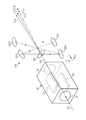
- FIG. 18 is a perspective view showing an amplifier and an OPS arranged at the subsequent stage of the amplifier.
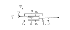
- FIG. 19 is a diagram illustrating a configuration of an amplifier according to a first modification.
- FIG. 20 is a diagram illustrating a configuration of an amplifier according to a second modification.
- FIG. 1 schematically illustrates a configuration of a laser system 2 according to a comparative example.
- the laser system 2 includes a solid-state laser device 3 as a master oscillator, an optical pulse stretcher (OPS) 10, a beam expander 20, and an amplifier 30.
- OPS optical pulse stretcher
- the solid-state laser device 3 includes a semiconductor laser, an amplifier, a nonlinear crystal, and the like (not shown).
- the solid-state laser device 3 outputs pulsed laser light PL in a single transverse mode.
- the pulse laser beam PL is a Gaussian beam, and has a center wavelength in a wavelength range of 193.1 nm to 193.5 nm and a spectral line width of about 0.3 pm, for example.
- the solid-state laser device 3 may be a solid-state laser device including a titanium sapphire laser that outputs a narrow-band pulsed laser beam having a center wavelength of about 773.4 nm and a nonlinear crystal that outputs a fourth harmonic. Good.
- the OPS 10 includes a beam splitter 11 and first to fourth concave mirrors 12a to 12d.
- the beam splitter 11 is a partial reflection mirror.
- the reflectance of the beam splitter 11 is preferably in the range of 40% to 70%, and more preferably about 60%.
- the beam splitter 11 is disposed on the optical path of the pulse laser beam PL output from the solid-state laser device 3.
- the beam splitter 11 transmits a part of the incident pulsed laser light PL and reflects the other part.
- the first to fourth concave mirrors 12a to 12d constitute a delay optical path for extending the pulse width of the pulse laser beam PL.
- the first to fourth concave mirrors 12a to 12d all have mirror surfaces having the same curvature radius R.
- the first and second concave mirrors 12a and 12b are arranged so that the light reflected by the beam splitter 11 is reflected by the first concave mirror 12a and enters the second concave mirror 12b.
- the third and fourth concave mirrors 12c and 12d the light reflected by the second concave mirror 12b is reflected by the third concave mirror 12c, further reflected by the fourth concave mirror 12d, and again by the beam splitter.
- 11 is arranged so as to be incident on 11.
- the distance between the beam splitter 11 and the first concave mirror 12a and the distance between the fourth concave mirror 12d and the beam splitter 11 are each half the radius of curvature R, that is, R / 2. Further, the distance between the first concave mirror 12a and the second concave mirror 12b, the distance between the second concave mirror 12b and the third concave mirror 12c, and the third concave mirror 12c and the fourth concave mirror 12c. The distance from the concave mirror 12d is the same as the radius of curvature R.
- the first to fourth concave mirrors 12a to 12d all have the same focal length F.
- FIG. 2 is a diagram for explaining the positional relationship between the beam splitter 11 and the first to fourth concave mirrors 12a to 12d.
- the first to fourth concave mirrors 12a to 12d are replaced with convex lenses 13a to 13d having a focal length of F, respectively.
- P0 represents the position of the beam splitter 11.
- P1 to P4 represent the positions of the first to fourth concave mirrors 12a to 12d, respectively.
- the delay optical system constituted by the first to fourth concave mirrors 12a to 12d is a collimating optical system, when the incident light to the first concave mirror 12a is collimated light, the fourth concave mirror 12d The light emitted from the light becomes collimated light.
- the first to fourth concave mirrors 12a to 12d are arranged such that the optical path length L OPS is equal to or greater than the temporal coherent length L C of the pulse laser beam PL.
- ⁇ is the center wavelength of the pulse laser beam PL.
- the beam expander 20 is disposed on the optical path of the extended pulse laser beam PT output from the OPS 10.
- the extended pulse laser beam PT is light in which the pulse width of the pulse laser beam PL is extended by the OPS 10.
- the beam expander 20 includes a concave lens 21 and a convex lens 22. The beam expander 20 expands the beam diameter of the extended pulse laser beam PT input from the OPS 10 and outputs it.
- the amplifier 30 is disposed on the optical path of the extended pulse laser beam PT output from the beam expander 20.
- the amplifier 30 is an excimer laser device that includes a laser chamber 31, a pair of discharge electrodes 32 a and 32 b, a rear mirror 33, and an output coupling mirror 34.
- the rear mirror 33 and the output coupling mirror 34 are partial reflection mirrors and constitute a Fabry-Perot resonator.
- the rear mirror 33 and the output coupling mirror 34 are coated with a film that partially reflects light having a wavelength that causes laser oscillation.
- the reflectance of the partial reflection film of the rear mirror 33 is in the range of 80% to 90%.
- the reflectance of the partial reflection film of the output coupling mirror 34 is in the range of 20% to 40%.
- the laser chamber 31 is filled with a laser medium such as ArF laser gas.
- the pair of discharge electrodes 32a and 32b are disposed in the laser chamber 31 as electrodes for exciting the laser medium by discharge.
- a pulsed high voltage is applied between a pair of discharge electrodes 32a and 32b from a power source (not shown).
- the traveling direction of the extended pulse laser beam PT output from the beam expander 20 is referred to as the Z direction.
- a discharge direction between the pair of discharge electrodes 32a and 32b is referred to as a V direction.
- the V direction is orthogonal to the Z direction.
- the direction orthogonal to the Z direction and the V direction is referred to as the H direction.
- Windows 31 a and 31 b are provided at both ends of the laser chamber 31.
- the extended pulse laser beam PT output from the beam expander 20 passes through the rear mirror 33 and the window 31a and enters the discharge space 35 between the pair of discharge electrodes 32a and 32b as seed light.
- the width of the discharge space 35 in the V direction substantially coincides with the beam diameter expanded by the beam expander 20.
- the solid-state laser device 3 and the amplifier 30 are controlled by a synchronization control unit (not shown).
- the amplifier 30 is controlled by the synchronization control unit such that the amplifier 30 is discharged at the timing when the extended pulse laser beam PT enters the discharge space 35.
- the pulsed laser light PL output from the solid-state laser device 3 enters the beam splitter 11 in the OPS 10.
- a part of the pulsed laser light PL incident on the beam splitter 11 passes through the beam splitter 11 and is output from the OPS 10 as zero-round light PS 0 that does not go around the delay optical path.
- the reflected light reflected by the beam splitter 11 enters the delay optical path and is reflected by the first concave mirror 12a and the second concave mirror 12b.
- the light image of the reflected light from the beam splitter 11 is formed as a first-magnification first transfer image by the first and second concave mirrors 12a and 12b.
- the second transfer image of the same magnification is formed at the position of the beam splitter 11 by the third concave mirror 12c and the fourth concave mirror 12d.
- a part of the light that has entered the beam splitter 11 as the second transfer image is reflected by the beam splitter 11 and is output from the OPS 10 as one-round light PS 1 that has made one round of the delay optical path.
- c is the speed of light.
- the transmitted light that has passed through the beam splitter 11 again enters the delay optical path, is reflected by the first to fourth concave mirrors 12a to 12d, and again.
- the light enters the beam splitter 11.
- the reflected light reflected by the beam splitter 11 is output from the OPS 10 as the two-round light PS s that circulates the delay optical path twice.
- the two-round light PS s is output with a delay of ⁇ t from the one-round light PS 1 .
- the OPS 10 outputs pulsed light in order of the three-round light PS 3 , the four-round light PS 4 ,.
- the light intensity of the pulsed light output from the OPS 10 decreases as the number of circulations of the delayed optical path increases.
- the pulse laser beam PL is decomposed into a plurality of pulse beams PS 0 , PS 1 , PS 2 ,. .
- the horizontal axis represents time
- the vertical axis represents light intensity.
- n represents the number of circulations of the delay optical path.
- the optical path length L OPS is equal to or greater than the temporal coherent length L C , the mutual coherence of the plurality of pulse lights PS n is reduced. Therefore, coherence of elongated pulse laser beam PT constituted by a plurality of light pulses PS n decreases.
- the extended pulse laser beam PT output from the OPS 10 enters the beam expander 20, and the beam expander 20 increases the beam diameter and outputs it.
- the extended pulse laser beam PT output from the beam expander 20 enters the amplifier 30.
- the extended pulse laser beam PT incident on the amplifier 30 passes through the rear mirror 33 and the window 31a and enters the discharge space 35 as seed light.
- discharge is generated by a power source (not shown) in synchronization with the incident of the extended pulse laser beam PT.
- the extended pulse laser beam PT passes through the discharge space 35 excited by the discharge, so that stimulated emission occurs and is amplified.
- the amplified extended pulse laser beam PT is oscillated by the optical resonator and output from the output coupling mirror 34.
- the laser system 2 outputs the extended pulse laser beam PT having a reduced peak power level and reduced coherence compared to the pulse laser beam PL output from the solid-state laser device 3.
- the pulse width TIS of the laser beam is defined by the following formula 1.
- t is time.
- I (t) is the light intensity at time t.
- the pulse width of the extended pulse laser beam PT is obtained using the following formula 1.
- the coherence is reduced by temporally decomposing the pulsed laser light PL by the OPS 10, but the pulsed laser light is further reduced. It is possible to reduce coherence by spatially decomposing PL.
- FIG. 4 shows a configuration of the OPS 40 that makes it possible to decompose the pulsed laser light PL temporally and spatially.
- the OPS 40 has the same configuration as the OPS 10 described above except that the arrangement of the fourth concave mirror 12d is different.
- the fourth concave mirror 12d is disposed at a position slightly rotated about the H direction as the rotation axis with respect to the position of the fourth concave mirror 12d of the OPS 10 indicated by a broken line.
- the emission angles of the plurality of pulse lights PS n output from the OPS 40 change in the V direction according to the number of times n of the delay optical path. That is, a plurality of light pulses PS n output from OPS40 the optical path axis are different from each other.
- a plurality of light pulses PS n output from OPS40 is spatially resolved in the V direction is incident on the beam expander 20.
- the incident direction of the pulsed laser light PL to the OPS 40 is slightly inclined from the Z direction.
- the plurality of light pulses PS n depending on the number of turns n of the delay optical path, passes through the optical path in the discharge space 35 is different.
- OPS40 Because generates a plurality of pulsed light PS n of the pulsed laser beam PL temporally and spatially resolved, coherent output beam of the amplifier 30 is further reduced.
- the discharge space 35 is not filled with the seed light at the same time in the V direction.
- the seed light exists only for the time when the zero-round light PS 0 is incident. For this reason, there is no seed light on the optical path of the zero-round light PS 0 during the time when the round light after the first round light PS 1 is incident.
- the upper level lifetime which is the lifetime of the atoms excited to the upper level is as short as about 2 ns. For this reason, if there is a space in the discharge space 35 that is not filled with seed light, spontaneous emission occurs in that space before stimulated emission by the seed light occurs. As a result, the output light of the amplifier 30 includes a lot of amplified (ASE) light as a result of spontaneous emission, as well as amplified light by stimulated emission.
- ASE amplified
- the OPS 40 configured as shown in FIG. 4
- the coherence of the output light of the amplifier 30 is reduced, but the ASE light is increased.
- the reflectance of the optical resonator is increased, the energy in the optical resonator is increased, which may damage the optical element.
- the pulse width of the extended pulse laser light PT it is conceivable to increase the pulse width of the extended pulse laser light PT.
- the pulse width of the extended pulse laser beam PT is increased, the light intensity of the seed light is reduced, and components that do not contribute to amplification increase, so that more ASE light may be generated.
- the laser system according to the first embodiment is the same as the configuration of the laser system according to the comparative example shown in FIG. 1 except that the configuration of the OPS is different.
- substantially the same parts as those of the laser system according to the comparative example shown in FIG. 1 are denoted by the same reference numerals, and description thereof will be omitted as appropriate.
- FIG. 6 shows a configuration of the laser system 50 according to the first embodiment.
- the laser system 50 includes a solid-state laser device 3, an OPS 60, a beam expander 20, and an amplifier 30.
- the OPS 60 includes a beam splitter 61 and first to fourth concave mirrors 62a to 62d.
- the beam splitter 61 has the same configuration as the beam splitter 11 of the comparative example.
- the arrangement of the first to fourth concave mirrors 62a to 62d is the same as that of the comparative example.
- the distance between the beam splitter 61 and the first concave mirror 62a and the distance between the fourth concave mirror 62d and the beam splitter 61 are the radius of curvature R of the first to third concave mirrors 62a to 62c. Half, ie R / 2.
- the distance from the concave mirror 62d is the same as the radius of curvature R.
- the beam splitter 11 and the first to fourth concave mirrors 12a to 12d are arranged such that the optical path axis of the 0-round light PS 0 and the optical path axis of the 1-round light PS 1 output from the OPS 60 coincide with each other. Yes. That is, in the first embodiment, the optical path axis of the plurality of light pulses PS n output from OPS60 will match.
- FIG. 7 is a diagram for explaining the positional relationship between the beam splitter 61 and the first to fourth concave mirrors 62a to 62d.
- the first to fourth concave mirrors 62a to 62d are replaced with convex lenses 63a to 63c having a focal length F and a convex lens 63d having a focal length shorter than F, respectively.
- P0 represents the position of the beam splitter 61.
- P1 to P4 represent the positions of the first to fourth concave mirrors 62a to 62d, respectively.
- the delay optical system is a non-collimating optical system that does not satisfy the collimating condition. For this reason, when the incident light on the first concave mirror 62a is collimated light, the light emitted from the fourth concave mirror 62d becomes non-collimated light.
- the beam waist position is the position where the beam spot size is the smallest, and coincides with the position where the radius of curvature of the wavefront is a plane.
- the divergence angle represents the angular spread of the beam at a distance sufficiently away from the beam waist position.
- the extension pulse laser beam PT is periodically incident on the amplifier 30.
- the interval ⁇ PT of the extended pulse laser beam PT is preferably shorter than the upper level lifetime which is the lifetime of the atoms excited to the upper level in the amplifier 30. This upper level lifetime is about 2 ns.
- the pulse width ⁇ DT of the extended pulse laser beam PT may be made as long as possible.
- the interval ⁇ PT is a period in which the light intensity is almost zero. For example, it is assumed that the light intensity is 0 when the light intensity is 1% or less of the peak intensity.
- the optical path length L OPS may be set so as to satisfy the following expression 2.
- the pulse width ⁇ DT of the extended pulse laser beam PT preferably satisfies the following expression 3 when the optical path length of the optical resonator of the amplifier 30 is L amp .
- the pulsed laser light PL output from the solid state laser device 3 enters the beam splitter 61 in the OPS 60. Part of the pulsed laser light PL incident on the beam splitter 61 passes through the beam splitter 61 and is output from the OPS 60 as zero-round light PS 0 .
- FIG. 9A shows the zero-round light PS 0 output from the OPS 60.
- the zero-round light PS 0 is collimated light.
- the reflected light reflected by the beam splitter 61 enters a delay optical path constituted by the first to fourth concave mirrors 62a to 62d, and passes through the delay optical path once. It goes around and enters the beam splitter 61 again. A part of the light incident on the beam splitter 61 is reflected by the beam splitter 61 and output from the OPS 60 as one-round light PS 1 .
- FIG. 9B shows the one-round light PS 1 output from the OPS 60.
- the delay optical system is a non-collimating optical system
- the one-round light PS 1 becomes non-collimated light and converges far from the OPS 60. That is, one beam waist position w 1 of the orbiting beam PS 1 is located far from OPS60.
- FIG. 9C shows the two-round light PS 2 output from the OPS 60.
- Beam waist position w 2 of 2 circulating light PS 2 approaches the 1 OPS60 side than the beam waist position w 1 of the orbiting light PS 1.
- the OPS 60 outputs the pulse light in order of the three-round light PS 3 , the four-round light PS 4 ,. Greater the laps n delay optical path, the beam waist position w n of the output light from the OPS60, approaches OPS60 side.
- a plurality of light pulses PS n constitute the stretched pulse laser light PT.
- the extended pulse laser beam PT is expanded by the beam expander 20 so that the beam diameter matches the width of the discharge space 35, and enters the amplifier 30 as seed light.
- the extended pulse laser beam PT that has entered the amplifier 30 passes through the rear mirror 33 and the window 31 a and enters the discharge space 35.
- a plurality of light pulses PS n is the optical path axis respectively coincide with each other, overlapping in the discharge space 35.
- discharge is generated by a power source (not shown) in synchronization with the incident of the extended pulse laser beam PT.
- the extended pulse laser beam PT passes through the discharge space 35 excited by the discharge, so that stimulated emission occurs and is amplified.
- the amplified extended pulse laser beam PT is oscillated by the optical resonator and output from the output coupling mirror 34.
- Effect OPS60 is changed in addition to decomposition temporally pulsed laser beam PL, resolved plurality of pulse light PS n, without changing the traveling direction, the beam waist position w n in the optical path axis
- the plurality of light pulses PS n because each beam waist position w n and diverging angle theta n different, reduced coherence mutual further coherence constituted stretched pulse laser light PT in these Is further reduced.
- a plurality of light pulses PS n entering the discharge space 35 is seed light, since overlap with the discharge space 35, discharge space 35 is filled with simultaneously in time the seed light with respect to the V direction. Thereby, generation
- the discharge space 35 is filled with the seed light at any time during the discharge period. Generation is further suppressed.
- the laser system 50 according to the first embodiment can reduce the coherence of the output light and suppress the generation of ASE light.
- Figure 11A for the beam waist positions are schematic views for explaining a method of measuring the change in the beam waist position w n of the plurality of light pulses PS n output from OPS60 of the first embodiment.
- An ideal lens 70 having a focal length f is arranged on the optical path axis of the output light of the OPS 60, and the condensing position of the output light by the ideal lens 70 is measured. This condensing position corresponds to the beam waist position.
- the ideal lens 70 is a lens that can ignore aberrations. As shown in FIG. 12, the condensing position is obtained by measuring the position where the spot diameter of the beam is minimum.
- the condensing position FP 0 by the ideal lens 70 coincides with the focal position of the ideal lens 70.
- Condensing position FP 1 in one round light PS 1 by the ideal lens 70 is moved from the focusing position FP 0 the ideal lens 70 side.
- the condensing position FP 2 of the two-round light PS 2 by the ideal lens 70 moves to the ideal lens 70 side from the condensing position FP 1 .
- the condensing position approaches the ideal lens 70 side.
- Figure 11B shows a measurement example of a beam waist position w n of the plurality of light pulses PS n output from OPS40 described as a comparative example. Since the OPS 40 changes the traveling direction of the plurality of pulse lights PS n , the condensing positions FP 0 , FP 1 , FP 2 ,... Sequentially move in the V direction.
- the delay optical system is changed to a non-collimating optical system by changing the curvature of the fourth concave mirror 62d. It is set to become.
- the curvature of other concave mirrors may be changed without being limited to the fourth concave mirror 62d.
- the delay optical system may be a non-collimating optical system by making the curvature of at least one concave mirror of the plurality of concave mirrors constituting the delay optical system different from the curvature of other concave mirrors.
- FIG. 13 shows a configuration of an OPS 80 according to the first modification.
- the OPS 80 includes a beam splitter 81 and first to fourth concave mirrors 82a to 82d.
- the beam splitter 81 has the same configuration as the beam splitter 11 of the comparative example.
- the first to fourth concave mirrors 82a to 82d all have mirror surfaces having the same curvature radius R.
- the first to fourth concave mirrors 82a to 82d all have the same focal length F.
- the OPS 80 has the same configuration as the OPS 10 according to the comparative example except that the position of the fourth concave mirror 82d is different.
- the fourth concave mirror 82d is moved in the direction of increasing the optical path length L OPS of the delayed optical path from the position of the fourth concave mirror 12d of the OPS 10 indicated by a broken line. Specifically, the distance between the third concave mirror 62c and the fourth concave mirror 62d is longer than twice the focal length F, and the distance between the fourth concave mirror 62d and the beam splitter 61 is increased. The distance is made longer than the focal length F. That is, the OPS 80 has a relationship of L OPS > 8F.
- the delay optical system constituted by the first to fourth concave mirrors 82a to 82d is a non-collimating optical system, the circulating light that has circulated in the delay optical path becomes non-collimated light.
- the divergence angle ⁇ n changes according to the number of times n of the delay optical path, and the beam waist position w n moves in the Z direction.
- the optical path axis of the plurality of light pulses PS n is almost the same.
- the concave mirror that moves in the direction of increasing the optical path length L OPS is not limited to the fourth concave mirror 82d, and may be other concave mirrors. What is necessary is just to move at least 1 concave-surface mirror among the several concave-surface mirrors which comprise a delay optical system from the position which satisfy
- FIG. 14 shows a configuration of an OPS 90 according to the second modification.
- the OPS 90 includes a beam splitter 91, first to fourth concave mirrors 92a to 92d, a first lens 93, and a second lens 94.
- the beam splitter 91 has the same configuration as the beam splitter 11 of the comparative example.
- the first and second lenses 93 and 94 are made of synthetic quartz or calcium fluoride (CaF 2 ).
- the first lens 93 is disposed on the optical path between the second concave mirror 92b and the third concave mirror 92c.
- the first lens 93 is a concave lens and changes the divergence angle of incident light and emits it.
- the first lens 93 sets the delay optical system to be a non-collimating optical system.
- the second lens 94 is disposed on the optical path of the pulsed laser light PL that is incident on the beam splitter 91.
- the second lens 94 is a concave lens and is provided to correct the divergence angle changed by the first lens 93. Note that the second lens 94 is not an essential component and may be omitted.
- the delay optical system constituted by the first to fourth concave mirrors 92a to 92d and the first lens 93 is a non-collimating optical system, the circulating light that has circulated around the delay optical path becomes non-collimated light.
- the divergence angle ⁇ n changes according to the number of times n of the delay optical path, and the beam waist position w n moves in the Z direction.
- the optical path axis of the plurality of light pulses PS n is almost the same.
- the first lens 93 is not limited to the optical path between the second concave mirror 92b and the third concave mirror 92c, but on the optical path between the fourth concave mirror 92d and the beam splitter 91, or the beam splitter. You may arrange
- the first and second lenses 93 and 94 are not limited to concave lenses, and may be constituted by other optical elements.
- the first and second lenses 93 and 94 may be cylindrical lenses, respectively.
- each of the first and second lenses 93 and 94 may be a combination of two cylindrical lenses whose bending directions are orthogonal to each other.
- the laser system according to the second embodiment is the same as the configuration of the laser system 50 according to the first embodiment shown in FIG. 6 except that the configuration of the OPS is different.
- the OPS is configured to include a plurality of concave mirrors.
- the OPS is configured to include a condenser lens.
- FIG. 15 shows the configuration of the OPS 100 used in the laser system according to the second embodiment.
- the OPS 100 includes a beam splitter 101, first to fourth high reflection mirrors 102a to 102d, and first to fifth condenser lenses 103 to 107.
- the beam splitter 101 has the same configuration as the beam splitter 61 of the first embodiment.
- the first to fifth condenser lenses 103 to 107 are convex lenses, respectively.
- the first and second condenser lenses 103 and 104 are a first lens group for adjusting the divergence angle ⁇ 0 of the 0-round light PS 0 .
- the first condenser lens 103 is arranged on the optical path until the pulse laser beam PL incident from the solid-state laser device 3 enters the beam splitter 101.
- the second condenser lens 104 is disposed on the optical path of the light transmitted through the beam splitter 101 in the pulsed laser light PL.
- the second condenser lens 104 is held by the uniaxial stage 104a.
- the uniaxial stage 104a makes it possible to move the second condenser lens 104 in the Z direction, which is the optical path axis direction.
- the divergence angle ⁇ 0 of the zero-circular light PS 0 can be adjusted.
- FIG. 16A shows the positional relationship between the first and second condenser lenses 103 and 104.
- P ⁇ b> 1 represents the position of the first condenser lens 103.
- P ⁇ b> 2 represents the position of the second condenser lens 104.
- P0 represents the position of the beam splitter 101.
- the focal length of the first condenser lens 103 is F 1
- the focal length of the second condenser lens 104 is F 2 .
- the position P2 is set such that the optical path length between the position P1 and the position P2 is “F 1 + F 2 ”. That is, the first lens group is a collimating optical system.
- the first lens group may be a non-collimating optical system by shifting the position P2 from a position that satisfies the collimating condition.
- the first to fourth high reflection mirrors 102a to 102d and the second lens group including the third to fifth condenser lenses 105 to 107 constitute a delay optical path.
- the first to fourth high reflection mirrors 102a to 102d are flat mirrors having a high reflection film formed on the surface.
- the substrates of the first to fourth high reflection mirrors 102a to 102d are made of synthetic quartz or calcium fluoride (CaF 2 ).
- the highly reflective film is a dielectric multilayer film, for example, a film containing fluoride.
- the first to fourth high reflection mirrors 102a to 102d are arranged so that the light reflected by the beam splitter 101 of the pulsed laser light PL is sequentially highly reflected and incident on the beam splitter 61 again. .
- the third and fourth condenser lenses 105 and 106 are disposed between the beam splitter 101 and the first high reflection mirror 102a.
- the fifth condenser lens 107 is disposed between the second high reflection mirror 102b and the third high reflection mirror 102c.
- the fourth condenser lens 106 is held by the uniaxial stage 106a.
- the uniaxial stage 104a makes it possible to move the fourth condenser lens 106 in the V direction that is the optical path axis direction.
- the divergence angle ⁇ n of the n-circular light PS n (n ⁇ 1) can be adjusted.
- FIG. 16B and 17 show the positional relationship between the first to fifth condenser lenses 103 to 107.
- FIG. P 3 represents the position of the third condenser lens 105.
- P4 represents the position of the fourth condenser lens 106.
- P5 represents the position of the fifth condenser lens 107.
- the focal length of the third condenser lens 105 is F 3
- the focal distance of the fourth condenser lens 106 is F 4
- the focal distance of the fifth condenser lens 107 is F 5 .
- the position P3 is set so that the optical path length between the position P1 and the position P3 is “F 1 + F 3 ”.
- P4 ′ represents the position of the fourth condenser lens 106 when the delayed optical path satisfies the collimating condition.
- the optical path length between the position P4 ′ and the position P5 is “F 4 + 2F 5 ”
- the optical path length between the position P2 and the position P5 is “F 2 + 2F 5 ”
- the position of the fourth condenser lens 106 is adjusted in the optical path axis direction by the uniaxial stage 106a so that the delay optical system becomes a non-collimating optical system, that is, the position P4 is shifted from the position P4 ′. ing.
- the beam splitter 101, the first to fourth high reflection mirrors 102a to 102d, and the first to fifth condenser lenses 103 to 107 are connected to the optical path axis of the zero-round light PS 0 output from the OPS 100. 1 and the optical path axis of the orbiting light PS 1 is arranged to coincide. That is, in the second embodiment, the optical path axis of the plurality of light pulses PS n output from OPS100 will match.
- L OPS represents the optical path length of the delay optical path.
- the optical path length L OPS satisfies the relationship of Equation 2 described above.
- the pulse width ⁇ DT of the extension pulse laser beam PT generated by the OPS 100 satisfies the relationship of the above-described Expression 3.
- the pulsed laser light PL output from the solid-state laser device 3 enters the beam splitter 101 via the first condenser lens 103. Part of the pulsed laser light PL that has entered the beam splitter 101 passes through the beam splitter 101 and enters the second condenser lens 104. The light emitted from the second condenser lens 104 is output from the OPS 100 as 0-round light PS 0 . As shown in FIG. 16A, the zero-round light PS 0 is collimated light.
- the reflected light reflected by the beam splitter 101 enters the delayed optical path.
- the reflected light that has entered the delayed optical path is reflected by the third condenser lens 105, the fourth condenser lens 106, the first high reflection mirror 102a, the second high reflection mirror 102b, the fifth condenser lens 107,
- the light enters the beam splitter 101 again via the third high reflection mirror 102c and the fourth high reflection mirror 102d.
- a part of the light incident on the beam splitter 101 is reflected by the beam splitter 101 and enters the second condenser lens 104.
- the light emitted from the second condenser lens 104 is output from the OPS 100 as one-round light PS 1 .
- the one-round light PS 1 is non-collimated light and converges far from the OPS 100. That is, one beam waist position w 1 of the orbiting beam PS 1 is located far from OPS100.
- the transmitted light that has passed through the beam splitter 101 enters the delay optical path again, goes around the delay optical path once more, and enters the beam splitter 101 again.
- a part of the light incident on the beam splitter 101 is reflected by the beam splitter 101 and output from the OPS 100 as the two-round light PS 2 through the second condenser lens 104.
- FIG. 17 shows the two-round light PS 2 output from the OPS 100. Beam waist position w 2 of 2 circulating light PS 2 approaches the 1 OPS100 side than the beam waist position w 1 of the orbiting light PS 1.
- the OPS 100 outputs the pulsed light in order of the three-round light PS 3 , the four-round light PS 4 ,. Greater the laps n delay optical path, the beam waist position w n of the output light from OPS100, approaches OPS100 side.
- the following operation is the same as the operation of the laser system 50 according to the first embodiment, and a description thereof will be omitted.
- the laser system according to the second embodiment can reduce the coherence of the output light and suppress the generation of ASE light, as in the first embodiment.
- the laser system according to the second embodiment by adjusting the positions of the second condenser lens 104 and the fourth condenser lens 106, the divergence angle ⁇ n and the beam waist position of the n-circular light PS n are adjusted. w n can be adjusted.
- the first lens group is provided to adjust the divergence angle ⁇ 0 of the zero-round light PS 0 , but the first lens group is not an essential component. Arrangement of a plurality of highly reflective mirrors and condenser lenses constituting the delay optical system can be changed as appropriate.
- Example in which OPS is placed after amplifier In the laser system according to the first and second embodiments, OPS is placed between solid-state laser device 3 and amplifier 30, but OPS is further placed after amplifier 30. You may arrange. The OPS arranged between the solid-state laser device 3 and the amplifier 30 corresponds to the first optical pulse stretcher. An OPS arranged after the amplifier corresponds to the second optical pulse stretcher.
- FIG. 18 is a perspective view showing the amplifier 30 and the OPS 200 arranged at the subsequent stage of the amplifier 30.
- the OPS 200 includes a beam splitter 201 and first to fourth concave mirrors 202a to 202d.
- the OPS 200 has the same configuration as the OPS 40 shown in FIG.
- the first to fourth concave mirrors 202a to 202d all have mirror surfaces having the same radius of curvature.
- the optical path length of the delay optical path constituted by the first to fourth concave mirrors 202a to 202d is eight times the focal length.
- the fourth concave mirror 202d is disposed at a position slightly rotated about the Z direction as the rotation axis with respect to the position satisfying the collimating condition.
- the output light PA output from the amplifier 30 is spatially decomposed in the H direction by the OPS 200.
- the fourth concave mirror 202d is preferably rotated in a range where the output light from the laser system does not affect the optical system of the exposure apparatus.
- any of the above-described OPSs 40, 60, 80, 90, and 100 may be applied instead of the OPS 200.
- a plurality of OPSs may be arranged after the amplifier 30.
- the OPS 40 may be disposed after the OPS 200 disposed after the amplifier 30, and the output light PA from the amplifier 30 may be decomposed in the H direction and the V direction.
- FIG. 19 shows a configuration of an amplifier 300 according to a first modification.
- the amplifier 300 includes a concave mirror 310 and a convex mirror 320 in place of the rear mirror 33 and the output coupling mirror 34 in the configuration of the amplifier 30 shown in FIG.
- the concave mirror 310 and the convex mirror 320 are arranged so that the extended pulse laser beam PT passes through the discharge space 35 between the pair of discharge electrodes 32a and 32b three times and the beam is expanded.
- the other configuration of the amplifier 300 is the same as that of the amplifier 30.
- Amplifier 300 is referred to as a multipath amplifier.
- the above-described beam expander 20 can be omitted.
- FIG. 20 shows a configuration of an amplifier 400 according to the second modification.
- an amplifier 400 includes a laser chamber 31, an output coupling mirror 410, and high reflection mirrors 420 to 422.
- the high reflection mirrors 420 to 422 are plane mirrors.
- the amplifier 400 may include a high reflection mirror for guiding the extended pulse laser beam PT to the high reflection mirror 420.
- the output coupling mirror 410 and the high reflection mirrors 420 to 422 constitute a ring resonator.
- the extended pulse laser beam PT is repeatedly amplified in the order of the output coupling mirror 410, the high reflection mirror 420, the discharge space 35, the high reflection mirror 421, the high reflection mirror 422, and the discharge space 35.
- the high reflection mirrors 420 to 422 may be concave mirrors so that the divergence angle changes every time the light incident on the resonator circulates in the resonator.
- the beam waist position of the output light from the output coupling mirror 410 changes in the direction of the optical path axis according to the number of circulations in the resonator.
- the amplifier 400 can have a function of reducing the coherence of the output light.
- the solid-state laser device 3 as a master oscillator is used.
- the master oscillator is not limited to the solid-state laser device, and may be other laser devices such as an excimer laser device. Good.
Landscapes
- Physics & Mathematics (AREA)
- Electromagnetism (AREA)
- Engineering & Computer Science (AREA)
- Plasma & Fusion (AREA)
- Optics & Photonics (AREA)
- General Physics & Mathematics (AREA)
- Life Sciences & Earth Sciences (AREA)
- Sustainable Development (AREA)
- Lasers (AREA)
- Exposure And Positioning Against Photoresist Photosensitive Materials (AREA)
Abstract
レーザシステムは、以下を備える:A.パルスレーザ光を出力するレーザ装置;及び、B.パルスレーザ光のパルス幅を伸長するための遅延光路を含む第1の光学パルスストレッチャであって、遅延光路を周回して出力される周回光のビームウェスト位置を、周回数に応じて光路軸方向に変化させるように構成された第1の光学パルスストレッチャ。周回光は、理想レンズで集光した場合に、集光位置が、周回数に応じて光路軸方向に変化する。
Description
本開示は、レーザ装置及び光学パルスストレッチャを含むレーザシステムに関する。
半導体集積回路の微細化、高集積化につれて、半導体露光装置においては解像力の向上が要請されている。半導体露光装置を以下、単に「露光装置」という。このため露光用光源から出力される光の短波長化が進められている。露光用光源には、従来の水銀ランプに代わってガスレーザ装置が用いられている。現在、露光用レーザ装置としては、波長248nmの紫外線を出力するKrFエキシマレーザ装置ならびに、波長193.4nmの紫外線を出力するArFエキシマレーザ装置が用いられている。
現在の露光技術としては、露光装置側の投影レンズとウエハ間の間隙を液体で満たして、当該間隙の屈折率を変えることによって、露光用光源の見かけ上の波長を短波長化する液浸露光が実用化されている。ArFエキシマレーザ装置を露光用光源として用いて液浸露光が行われた場合は、ウエハには水中における波長134nmの紫外光が照射される。この技術をArF液浸露光という。ArF液浸露光はArF液浸リソグラフィーとも呼ばれる。
KrF、ArFエキシマレーザ装置の自然発振におけるスペクトル線幅は約350~400pmと広いため、露光装置側の投影レンズによってウエハ上に縮小投影されるレーザ光(紫外線光)の色収差が発生して解像力が低下する。そこで色収差が無視できる程度となるまでガスレーザ装置から出力されるレーザ光のスペクトル線幅を狭帯域化する必要がある。このためガスレーザ装置のレーザ共振器内には、狭帯域化素子を有する狭帯域化モジュール(Line Narrowing Module)が設けられている。この狭帯域化モジュールによりスペクトル線幅の狭帯域化が実現されている。狭帯域化素子は、エタロンやグレーティング等であってもよい。このようにスペクトル線幅が狭帯域化されたレーザ装置を狭帯域化レーザ装置という。
また、レーザ装置には、露光装置の光学系に与えるダメージが小さくなるように、レーザ光のパルス幅を伸長する光学パルスストレッチャが用いられる。光学パルスストレッチャは、レーザ装置から出力されるレーザ光に含まれる各パルス光を、時間差を有する複数のパルス光に分解することにより、各パルス光のピークパワーレベルを下げる。
本開示の1つの観点に係るレーザシステムは、以下を備える:
A.パルスレーザ光を出力するレーザ装置;及び
B.パルスレーザ光のパルス幅を伸長するための遅延光路を含む第1の光学パルスストレッチャであって、遅延光路を周回して出力される周回光のビームウェスト位置を、周回数に応じて光路軸方向に変化させるように構成された第1の光学パルスストレッチャ。
A.パルスレーザ光を出力するレーザ装置;及び
B.パルスレーザ光のパルス幅を伸長するための遅延光路を含む第1の光学パルスストレッチャであって、遅延光路を周回して出力される周回光のビームウェスト位置を、周回数に応じて光路軸方向に変化させるように構成された第1の光学パルスストレッチャ。
本開示のいくつかの実施形態を、単なる例として、添付の図面を参照して以下に説明する。
図1は、比較例に係るレーザシステムの構成を概略的に示す図である。
図2は、ビームスプリッタ及び第1~第4の凹面ミラーの位置関係を説明する図である。
図3は、OPSからの出力光について説明する図である。
図4は、パルスレーザ光を時間的及び空間的に分解するOPSの構成を示す図である。
図5は、伸長パルスレーザ光の放電空間内への入射光路を説明する図である。
図6は、第1の実施形態に係るレーザシステムの構成を示す図である。
図7は、ビームスプリッタ及び第1~第4の凹面ミラーの位置関係を説明する図である。
図8は、増幅器に入射される伸長パルスレーザ光について説明する図である。
図9Aは、OPSから出力される0周回光について説明する図である。図9Bは、OPSから出力される1周回光について説明する図である。図9Cは、OPSから出力される2周回光について説明する図である。
図10は、伸長パルスレーザ光の放電空間内への入射光路を説明する図である。
図11Aは、第1の実施形態のOPSからの出力光のビームウェスト位置の変化を計測する方法を説明する模式図である。図11Bは、比較例のOPSからの出力光のビームウェスト位置の変化の計測例を示す図である。
図12は、OPSからの出力光のスポット径の変化を例示する図である。
図13は、第1の変形例に係るOPSの構成を示す図である。
図14は、第2の変形例に係るOPSの構成を示す図である。
図15は、第2の実施形態に係るレーザシステムに用いられるOPSの構成を示す図である。
図16Aは、OPSから出力される0周回光について説明する図である。図16Bは、OPSから出力される1周回光について説明する図である。
図17は、OPSから出力される2周回光について説明する図である。
図18は、増幅器と、増幅器の後段に配置されたOPSとを示す斜視図である。
図19は、第1の変形例に係る増幅器の構成を示す図である。
図20は、第2の変形例に係る増幅器の構成を示す図である。
<内容>
1.比較例
1.1 構成
1.2 動作
1.3 パルス幅の定義
1.4 課題
1.4.1 空間分解による可干渉性の低下
2.第1の実施形態
2.1 構成
2.2 動作
2.3 効果
2.4 ビームウェスト位置について
2.5 OPSの変形例
2.5.1 第1の変形例
2.5.2 第2の変形例
3.第2の実施形態
3.2 動作
3.3 効果
4.増幅器の後段にOPSを配置する例
5.増幅器の変形例
5.1 第1の変形例
5.2 第2の変形例
1.比較例
1.1 構成
1.2 動作
1.3 パルス幅の定義
1.4 課題
1.4.1 空間分解による可干渉性の低下
2.第1の実施形態
2.1 構成
2.2 動作
2.3 効果
2.4 ビームウェスト位置について
2.5 OPSの変形例
2.5.1 第1の変形例
2.5.2 第2の変形例
3.第2の実施形態
3.2 動作
3.3 効果
4.増幅器の後段にOPSを配置する例
5.増幅器の変形例
5.1 第1の変形例
5.2 第2の変形例
以下、本開示の実施形態について、図面を参照しながら詳しく説明する。以下に説明される実施形態は、本開示のいくつかの例を示すものであって、本開示の内容を限定するものではない。また、各実施形態で説明される構成及び動作の全てが本開示の構成及び動作として必須であるとは限らない。なお、同一の構成要素には同一の参照符号を付して、重複する説明を省略する。
1.比較例
1.1 構成
図1は、比較例に係るレーザシステム2の構成を概略的に示す。図1において、レーザシステム2は、マスターオシレータとしての固体レーザ装置3と、光学パルスストレッチャ(OPS:Optical Pulse Stretcher)10と、ビームエキスパンダ20と、増幅器30と、を含む。
1.1 構成
図1は、比較例に係るレーザシステム2の構成を概略的に示す。図1において、レーザシステム2は、マスターオシレータとしての固体レーザ装置3と、光学パルスストレッチャ(OPS:Optical Pulse Stretcher)10と、ビームエキスパンダ20と、増幅器30と、を含む。
固体レーザ装置3は、図示しない半導体レーザ、増幅器、非線形結晶等を含んで構成されている。固体レーザ装置3は、シングル横モードで、パルスレーザ光PLを出力する。パルスレーザ光PLは、ガウシアンビームであって、例えば、中心波長が193.1nm~193.5nmの波長範囲内であり、かつスペクトル線幅が約0.3pmである。固体レーザ装置3は、中心波長が約773.4nmの狭帯域化されたパルスレーザ光を出力するチタンサファイアレーザと、4倍高調波を出力する非線形結晶と、を含む固体レーザ装置であってもよい。
OPS10は、ビームスプリッタ11と、第1~第4の凹面ミラー12a~12dと、を含む。ビームスプリッタ11は、部分反射ミラーである。ビームスプリッタ11の反射率は、40%~70%の範囲内であることが好ましく、約60%であることがより好ましい。ビームスプリッタ11は、固体レーザ装置3から出力されるパルスレーザ光PLの光路上に配置されている。ビームスプリッタ11は、入射したパルスレーザ光PLの一部を透過させるとともに、他の一部を反射させる。
第1~第4の凹面ミラー12a~12dは、パルスレーザ光PLのパルス幅を伸長するための遅延光路を構成している。第1~第4の凹面ミラー12a~12dは、全て同じ曲率半径Rの鏡面を有する。第1及び第2の凹面ミラー12a,12bは、ビームスプリッタ11で反射された光が、第1の凹面ミラー12aで反射され、第2の凹面ミラー12bに入射するように配置されている。第3及び第4の凹面ミラー12c,12dは、第2の凹面ミラー12bで反射された光が、第3の凹面ミラー12cで反射され、さらに第4の凹面ミラー12dで反射され、再びビームスプリッタ11に入射するように配置されている。
ビームスプリッタ11と第1の凹面ミラー12aとの間の距離、及び第4の凹面ミラー12dとビームスプリッタ11との間の距離は、それぞれ曲率半径Rの半分、すなわち、R/2である。また、第1の凹面ミラー12aと第2の凹面ミラー12bとの間の距離、第2の凹面ミラー12bと第3の凹面ミラー12cとの間の距離、及び第3の凹面ミラー12cと第4の凹面ミラー12dとの間の距離は、それぞれ曲率半径Rと同じである。
第1~第4の凹面ミラー12a~12dは、全て同じ焦点距離Fを有する。焦点距離Fは、曲率半径Rの半分、すなわち、F=R/2である。したがって、第1~第4の凹面ミラー12a~12dにより構成される遅延光路の光路長LOPSは、焦点距離Fの8倍である。すなわち、OPS10は、LOPS=8Fの関係を有する。
図2は、ビームスプリッタ11及び第1~第4の凹面ミラー12a~12dの位置関係を説明する図である。図2では、第1~第4の凹面ミラー12a~12dを、それぞれ焦点距離がFである凸レンズ13a~13dに置き換えて示している。P0は、ビームスプリッタ11の位置を表している。P1~P4は、それぞれ第1~第4の凹面ミラー12a~12dの位置を表している。
第1~第4の凹面ミラー12a~12dにより構成される遅延光学系は、コリメート光学系であるので、第1の凹面ミラー12aへの入射光がコリメート光である場合、第4の凹面ミラー12dからの射出光はコリメート光となる。
また、第1~第4の凹面ミラー12a~12dは、光路長LOPSが、パルスレーザ光PLの時間的コヒーレント長LC以上となるように配置されている。時間的コヒーレント長LCは、LC=λ2/Δλの関係式に基づいて算出される。ここで、λは、パルスレーザ光PLの中心波長である。Δλは、パルスレーザ光PLのスペクトル線幅である。例えば、λ=193.35nm、Δλ=0.3pmの場合には、LC=0.125mとなる。
ビームエキスパンダ20は、OPS10から出力される伸長パルスレーザ光PTの光路上に配置されている。伸長パルスレーザ光PTは、パルスレーザ光PLのパルス幅がOPS10により伸長された光である。ビームエキスパンダ20は、凹レンズ21と凸レンズ22とを含む。ビームエキスパンダ20は、OPS10から入力された伸長パルスレーザ光PTを、そのビーム径を拡大して出力する。
増幅器30は、ビームエキスパンダ20から出力される伸長パルスレーザ光PTの光路上に配置されている。増幅器30は、レーザチャンバ31と、一対の放電電極32a及び32bと、リアミラー33と、出力結合ミラー34と、を含むエキシマレーザ装置である。リアミラー33及び出力結合ミラー34は、部分反射ミラーであり、ファブリペロ共振器を構成している。リアミラー33及び出力結合ミラー34には、レーザ発振する波長の光を部分反射する膜がコートされている。リアミラー33の部分反射膜の反射率は、80%~90%の範囲内である。出力結合ミラー34の部分反射膜の反射率は、20%~40%の範囲内である。
レーザチャンバ31内には、ArFレーザガス等のレーザ媒質が充填されている。一対の放電電極32a及び32bは、レーザ媒質を放電により励起するための電極として、レーザチャンバ31内に配置されている。一対の放電電極32a及び32bの間には、図示しない電源からパルス状の高電圧が印加される。
以下、ビームエキスパンダ20から出力される伸長パルスレーザ光PTの進行方向を、Z方向と言う。一対の放電電極32a及び32bの間の放電方向を、V方向と言う。V方向は、Z方向に直交する。Z方向とV方向とに直交する方向をH方向と言う。
レーザチャンバ31の両端には、ウィンドウ31a及び31bが設けられている。ビームエキスパンダ20から出力された伸長パルスレーザ光PTは、リアミラー33及びウィンドウ31aを通過して一対の放電電極32a及び32bの間の放電空間35に、シード光として入射する。放電空間35のV方向に関する幅は、ビームエキスパンダ20により拡大されたビーム径とほぼ一致している。
固体レーザ装置3と増幅器30とは、図示しない同期制御部によって制御される。増幅器30は、伸長パルスレーザ光PTが放電空間35に入射したタイミングで放電するように、同期制御部によって制御される。
1.2 動作
次に、比較例に係るレーザシステム2の動作について説明する。まず、固体レーザ装置3から出力されたパルスレーザ光PLは、OPS10内のビームスプリッタ11に入射する。ビームスプリッタ11に入射したパルスレーザ光PLのうち一部は、ビームスプリッタ11を透過し、遅延光路を周回していない0周回光PS0としてOPS10から出力される。
次に、比較例に係るレーザシステム2の動作について説明する。まず、固体レーザ装置3から出力されたパルスレーザ光PLは、OPS10内のビームスプリッタ11に入射する。ビームスプリッタ11に入射したパルスレーザ光PLのうち一部は、ビームスプリッタ11を透過し、遅延光路を周回していない0周回光PS0としてOPS10から出力される。
ビームスプリッタ11に入射したパルスレーザ光PLのうち、ビームスプリッタ11により反射された反射光は、遅延光路に進入し、第1の凹面ミラー12aと第2の凹面ミラー12bとにより反射される。ビームスプリッタ11における反射光の光像は、第1及び第2の凹面ミラー12a,12bにより、等倍の第1の転写像として結像される。そして、第3の凹面ミラー12cと第4の凹面ミラー12dとによって、等倍の第2の転写像が、ビームスプリッタ11の位置に結像する。
第2の転写像としてビームスプリッタ11に入射した光の一部は、ビームスプリッタ11により反射され、遅延光路を1回周回した1周回光PS1としてOPS10から出力される。この1周回光PS1は、0周回光PS0から遅延時間Δtだけ遅れて出力される。このΔtは、Δt=LOPS/cと表される。ここで、cは光速である。
第2の転写像としてビームスプリッタ11に入射した光のうち、ビームスプリッタ11を透過した透過光は、再び遅延光路に進入し、第1~第4の凹面ミラー12a~12dにより反射されて、再びビームスプリッタ11に入射する。ビームスプリッタ11により反射された反射光は、遅延光路を2回周回した2周回光PSsとしてOPS10から出力される。この2周回光PSsは、1周回光PS1から遅延時間Δtだけ遅れて出力される。
この後、光の遅延光路の周回が繰り返されることにより、OPS10からは、3周回光PS3、4周回光PS4、・・・と、順にパルス光が出力される。OPS10から出力されるパルス光は、遅延光路の周回数が多くなるほど光強度が低下する。
図3に示すように、パルスレーザ光PLがOPS10に入射した結果、パルスレーザ光PLは、時間差を有する複数のパルス光PS0,PS1,PS2,・・・に分解されて出力される。図3において、横軸は時間を表し、縦軸は光強度を表している。前述の伸長パルスレーザ光PTは、パルスレーザ光PLがOPS10により分解されてなる複数のパルス光PSn(n=0,1,2,・・・)が合成されたものである。ここで、nは遅延光路の周回数を表す。
光路長LOPSが時間的コヒーレント長LC以上であるので、複数のパルス光PSnの相互の可干渉性(coherence)が低下する。したがって、複数のパルス光PSnで構成される伸長パルスレーザ光PTの可干渉性が低下する。
OPS10から出力された伸長パルスレーザ光PTは、ビームエキスパンダ20に入射し、ビームエキスパンダ20によりビーム径が拡大されて出力される。ビームエキスパンダ20から出力された伸長パルスレーザ光PTは、増幅器30に入射する。増幅器30に入射された伸長パルスレーザ光PTは、リアミラー33及びウィンドウ31aを通過して放電空間35にシード光として入射する。
放電空間35には、伸長パルスレーザ光PTが入射するのに同期して、図示しない電源により放電が生じる。伸長パルスレーザ光PTが、放電によって励起された放電空間35を通過することによって、誘導放出が生じ、増幅される。そして、増幅された伸長パルスレーザ光PTは、光共振器によって発振して、出力結合ミラー34から出力される。
この結果、レーザシステム2からは、固体レーザ装置3から出力されたパルスレーザ光PLに比べて、ピークパワーレベルが低下し、かつ可干渉性が低下した伸長パルスレーザ光PTが出力される。
1.3 パルス幅の定義
レーザ光のパルス幅TISは、下式1により定義される。ここで、tは時間である。I(t)は、時間tにおける光強度である。伸長パルスレーザ光PTのパルス幅は、下式1を用いて求められる。
レーザ光のパルス幅TISは、下式1により定義される。ここで、tは時間である。I(t)は、時間tにおける光強度である。伸長パルスレーザ光PTのパルス幅は、下式1を用いて求められる。

1.4 課題
次に、比較例に係るレーザシステム2の課題について説明する。レーザシステム2から露光装置に供給されるレーザ光は、可干渉性が低いほど好ましいため、さらなる可干渉性の低下が求められている。
次に、比較例に係るレーザシステム2の課題について説明する。レーザシステム2から露光装置に供給されるレーザ光は、可干渉性が低いほど好ましいため、さらなる可干渉性の低下が求められている。
1.4.1 空間分解による可干渉性の低下
比較例に係るレーザシステム2では、OPS10によりパルスレーザ光PLを時間的に分解することにより可干渉性を低下させているが、さらにパルスレーザ光PLを空間的に分解することにより可干渉性を低下させることが可能である。
比較例に係るレーザシステム2では、OPS10によりパルスレーザ光PLを時間的に分解することにより可干渉性を低下させているが、さらにパルスレーザ光PLを空間的に分解することにより可干渉性を低下させることが可能である。
図4は、パルスレーザ光PLを時間的及び空間的に分解することを可能とするOPS40の構成を示す。OPS40は、第4の凹面ミラー12dの配置が異なること以外は、前述のOPS10の構成と同一である。
図4において、第4の凹面ミラー12dは、破線で示すOPS10の第4の凹面ミラー12dの位置に対して、H方向を回転軸として僅かに回転させた位置に配置されている。この構成により、OPS40から出力される複数のパルス光PSnは、遅延光路の周回数nに応じて、出射角がV方向に変化する。すなわち、OPS40から出力される複数のパルス光PSnは、光路軸が互いに異なる。この結果、OPS40から出力される複数のパルス光PSnは、V方向に空間的に分解されてビームエキスパンダ20に入射する。なお、図4では、パルスレーザ光PLのOPS40への入射方向を、Z方向から僅かに傾けている。
図5は、ビームエキスパンダ20から出力された複数のパルス光PSnが、シード光として増幅器30の放電空間35に入射する光路を示す。このように、複数のパルス光PSnは、遅延光路の周回数nに応じて、放電空間35内の通過光路が異なる。OPS40は、パルスレーザ光PLを時間的及び空間的に分解した複数のパルス光PSnを生成するので、増幅器30の出力光の可干渉性がさらに低下する。
しかしながら、上記のようにパルスレーザ光PLを時間的及び空間的に分解すると、放電空間35は、V方向に関して時間的に同時にシード光で満たされることはない。例えば、放電空間35中の0周回光PS0が入射する空間は、0周回光PS0が入射する時間しかシード光が存在しない。このため、1周回光PS1以降の周回光が入射する時間には、0周回光PS0の光路上には、シード光は存在しない。
エキシマレーザである増幅器30では、上準位に励起された原子の寿命である上準位寿命が、2ns程度と短い。このため、放電空間35中にシード光で満たされない空間が存在すると、その空間では、シード光による誘導放出が生じる前に、自然放出が生じてしまう。この結果、増幅器30の出力光には、誘導放出による増幅光以外に、自然放出による増幅(ASE:Amplified Spontaneous Emission)光がノイズとして多く含まれることになる。
したがって、図4に示すように構成されたOPS40を用いると、増幅器30の出力光は、可干渉性が低下するが、ASE光が増加するという問題がある。このASE光の発生を抑制するためには、増幅器30の光共振器の反射率を高め、光共振器内にシード光をより多く存在させることが考えられる。しかし、光共振器の反射率を高めると、光共振器内のエネルギーが高くなり、光学素子損傷する可能性がある。
また、ASE光の発生を抑制するためには、伸長パルスレーザ光PTのパルス幅を長くすることが考えられる。しかし、伸長パルスレーザ光PTのパルス幅を長くすると、シード光の光強度が低下し、増幅に寄与しない成分が増加するため、ASE光がより多く発生する可能性がある。
2.第1の実施形態
次に、本開示の第1の実施形態に係るレーザシステムについて説明する。第1の実施形態に係るレーザシステムは、OPSの構成が異なること以外は、図1に示した比較例に係るレーザシステムの構成と同一である。以下では、図1に示した比較例に係るレーザシステムの構成要素と略同じ部分については、同一の符号を付し、適宜説明を省略する。
次に、本開示の第1の実施形態に係るレーザシステムについて説明する。第1の実施形態に係るレーザシステムは、OPSの構成が異なること以外は、図1に示した比較例に係るレーザシステムの構成と同一である。以下では、図1に示した比較例に係るレーザシステムの構成要素と略同じ部分については、同一の符号を付し、適宜説明を省略する。
1.1 構成
図6は、第1の実施形態に係るレーザシステム50の構成を示す。レーザシステム50は、固体レーザ装置3と、OPS60と、ビームエキスパンダ20と、増幅器30と、を含む。OPS60は、ビームスプリッタ61と、第1~第4の凹面ミラー62a~62dと、を含む。ビームスプリッタ61は、比較例のビームスプリッタ11と同一の構成である。
図6は、第1の実施形態に係るレーザシステム50の構成を示す。レーザシステム50は、固体レーザ装置3と、OPS60と、ビームエキスパンダ20と、増幅器30と、を含む。OPS60は、ビームスプリッタ61と、第1~第4の凹面ミラー62a~62dと、を含む。ビームスプリッタ61は、比較例のビームスプリッタ11と同一の構成である。
第1~第4の凹面ミラー62a~62dは、第4の凹面ミラー62dのみ、他のものとは鏡面の曲率半径が異なる。具体的には、第1の凹面ミラー62aの曲率半径をR1、第2の凹面ミラー62bの曲率半径をR2、第3の凹面ミラー62cの曲率半径をR3、第4の凹面ミラー62dの曲率半径をR4とすると、R1=R2=R3=R、及びR4<Rの関係を満たす。また、第1の凹面ミラー62aの焦点距離をF1、第2の凹面ミラー62bの焦点距離をF2、第3の凹面ミラー62cの焦点距離をF3、第4の凹面ミラー62dの焦点距離をF4とすると、F1=F2=F3=F、及びF4<Fの関係を満たす。
第1~第4の凹面ミラー62a~62dの配置は、比較例と同様である。ビームスプリッタ61と第1の凹面ミラー62aとの間の距離、及び第4の凹面ミラー62dとビームスプリッタ61との間の距離は、第1~第3の凹面ミラー62a~62cの曲率半径Rの半分、すなわち、R/2である。また、第1の凹面ミラー62aと第2の凹面ミラー62bとの間の距離、第2の凹面ミラー62bと第3の凹面ミラー62cとの間の距離、及び第3の凹面ミラー62cと第4の凹面ミラー62dとの間の距離は、それぞれ曲率半径Rと同じである。
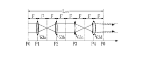
したがって、第1~第4の凹面ミラー62a~62dにより構成される遅延光路の光路長LOPSは第1~第3の凹面ミラー62a~62cの焦点距離Fの8倍、すなわち、LOPS=8Fである。なお、ビームスプリッタ11及び第1~第4の凹面ミラー12a~12dは、OPS60から出力される0周回光PS0の光路軸と1周回光PS1の光路軸とが一致するように配置されている。すなわち、第1の実施形態では、OPS60から出力される複数のパルス光PSnの光路軸は、全て一致する。
図7は、ビームスプリッタ61及び第1~第4の凹面ミラー62a~62dの位置関係を説明する図である。図7では、第1~第4の凹面ミラー62a~62dを、それぞれ焦点距離がFである凸レンズ63a~63cと、焦点距離がFより短い凸レンズ63dとに置き換えて示している。P0は、ビームスプリッタ61の位置を表している。P1~P4は、それぞれ第1~第4の凹面ミラー62a~62dの位置を表している。
LOPS=8Fであるのに対して、F1=F2=F3=F、及びF4<Fであるので、遅延光学系は、コリメート条件を満たさない非コリメート光学系である。このため、第1の凹面ミラー62aへの入射光がコリメート光である場合、第4の凹面ミラー62dからの射出光は非コリメート光となる。
OPS60は、比較例のOPS10と同様に、図3に示されるように、固体レーザ装置3から入射したパルスレーザ光PLを、時間差を有する複数のパルス光PSn(n=0,1,2,・・・)に分解し、伸長パルスレーザ光PTとして出力する。パルスレーザ光PLは、ガウシアンビームであるので、OPS60から出力される複数のパルス光PSnの各発散角θnは、遅延光路の周回数nに応じて変化する。また、複数のパルス光PSnの各ビームウェスト位置wnは、遅延光路の周回数nに応じてZ方向に移動する。発散角θnとビームウェスト位置wnとは、反比例の関係にある。発散角θn及びビームウェスト位置wnは、第4の凹面ミラー62dの曲率によって決定される。
ビームウェスト位置は、ビームのスポットサイズが最小となる位置であり、波面の曲率半径が平面となる位置と一致する。発散角は、ビームウェスト位置から十分離れた距離でのビームの角度広がりを表す。
図8に示すように、増幅器30には、伸長パルスレーザ光PTが周期的に入射される。ASE光の発生を抑制するために、伸長パルスレーザ光PTの間隔ΔPTは、増幅器30内で上準位に励起された原子の寿命である上準位寿命より短いことが好ましい。この上準位寿命は、約2nsである。このためには、伸長パルスレーザ光PTのパルス幅ΔDTを可能な限り長くすればよい。間隔ΔPTは、光強度がほぼ0となる期間である。例えば、光強度がピーク強度の1%以下である場合に、光強度が0であるとする。
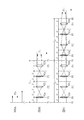
パルス幅ΔDTを長くするためには、前述の遅延時間Δtが、パルスレーザ光PLのパルス幅ΔDと一致するように、光路長LOPSを設定することが好ましい。この場合、光路長LOPSを、下式2を満たすように設定すればよい。
LOPS=c・ΔD ・・・(2)
パルス幅ΔDは、複数のパルス光PSnの各パルス幅とほぼ同一である。例えば、ΔD=3nmとすると、LOPS=1mとなり、光路長LOPSは、時間的コヒーレント長LC以上となる。
また、ASE光の発生を抑制するために、伸長パルスレーザ光PTのパルス幅ΔDTは、増幅器30の光共振器の光路長をLampとした場合に、下式3を満たすことが好ましい。なお、光共振器の光路長Lampは、リアミラー33と出力結合ミラー34との間の距離である共振器長Laの2倍、すなわち、Lamp=2Laである。
ΔDT≧Lamp/c ・・・(3)
2.2 動作
次に、第1の実施形態に係るレーザシステム50の動作について説明する。まず、固体レーザ装置3から出力されたパルスレーザ光PLは、OPS60内のビームスプリッタ61に入射する。ビームスプリッタ61に入射したパルスレーザ光PLのうち一部は、ビームスプリッタ61を透過し、0周回光PS0としてOPS60から出力される。図9Aは、OPS60から出力される0周回光PS0を示す。0周回光PS0は、コリメート光である。
次に、第1の実施形態に係るレーザシステム50の動作について説明する。まず、固体レーザ装置3から出力されたパルスレーザ光PLは、OPS60内のビームスプリッタ61に入射する。ビームスプリッタ61に入射したパルスレーザ光PLのうち一部は、ビームスプリッタ61を透過し、0周回光PS0としてOPS60から出力される。図9Aは、OPS60から出力される0周回光PS0を示す。0周回光PS0は、コリメート光である。
ビームスプリッタ61に入射したパルスレーザ光PLのうち、ビームスプリッタ61により反射された反射光は、第1~第4の凹面ミラー62a~62dにより構成される遅延光路に進入し、遅延光路を1回周回して再びビームスプリッタ61に入射する。ビームスプリッタ61に入射した光の一部は、ビームスプリッタ61により反射され、1周回光PS1としてOPS60から出力される。図9Bは、OPS60から出力される1周回光PS1を示す。前述のように、遅延光学系は非コリメート光学系であるので、1周回光PS1は、非コリメート光となり、OPS60から遠くに収束する。すなわち、1周回光PS1のビームウェスト位置w1は、OPS60から遠くに位置する。
ビームスプリッタ61に入射した光のうち、ビームスプリッタ61を透過した透過光は、再び遅延光路に進入し、遅延光路をさらに1回周回して再びビームスプリッタ61に入射する。ビームスプリッタ61に入射した光の一部は、ビームスプリッタ61により反射され、2周回光PS2としてOPS60から出力される。図9Cは、OPS60から出力される2周回光PS2を示す。2周回光PS2のビームウェスト位置w2は、1周回光PS1のビームウェスト位置w1よりもOPS60側に近づく。
この後、光の遅延光路の周回が繰り返されることにより、OPS60からは、3周回光PS3、4周回光PS4、・・・と、順にパルス光が出力される。遅延光路の周回数nが多くなるほど、OPS60からの出力光のビームウェスト位置wnは、OPS60側に近づく。
パルスレーザ光PLがOPS60に入射した結果、パルスレーザ光PLは、時間差を有する複数のパルス光PSn(n=0,1,2,・・・)に分解されて出力される。複数のパルス光PSnは、伸長パルスレーザ光PTを構成する。
図10に示すように、伸長パルスレーザ光PTは、ビームエキスパンダ20によりビーム径が、放電空間35の幅に合うように拡大され、シード光として増幅器30に入射する。増幅器30に入射した伸長パルスレーザ光PTは、リアミラー33及びウィンドウ31aを通過して放電空間35に入射する。複数のパルス光PSnは、それぞれ光路軸が一致しているので、放電空間35内で重なり合う。
放電空間35には、伸長パルスレーザ光PTが入射するのに同期して、図示しない電源により放電が生じる。伸長パルスレーザ光PTが、放電によって励起された放電空間35を通過することによって、誘導放出が生じ、増幅される。そして、増幅された伸長パルスレーザ光PTは、光共振器によって発振して、出力結合ミラー34から出力される。
2.3 効果
OPS60は、パルスレーザ光PLを時間的に分解することに加え、分解された複数のパルス光PSnを、進行方向を変えずに、ビームウェスト位置wnを光路軸方向に変化させる。これにより、複数のパルス光PSnは、それぞれビームウェスト位置wn及び発散角θnが異なるので、相互の可干渉性がさらに低下し、これらで構成される伸長パルスレーザ光PTの可干渉性がさらに低下する。
OPS60は、パルスレーザ光PLを時間的に分解することに加え、分解された複数のパルス光PSnを、進行方向を変えずに、ビームウェスト位置wnを光路軸方向に変化させる。これにより、複数のパルス光PSnは、それぞれビームウェスト位置wn及び発散角θnが異なるので、相互の可干渉性がさらに低下し、これらで構成される伸長パルスレーザ光PTの可干渉性がさらに低下する。
また、シード光として放電空間35内に入射する複数のパルス光PSnは、放電空間35内で重なり合うので、放電空間35内がV方向に関して時間的に同時にシード光で満たされる。これにより、ASE光の発生が抑制される。
さらに、伸長パルスレーザ光PTのパルス幅ΔDTを、前述の式3を満たすように設定することにより、放電期間中の何れの時間においても放電空間35内がシード光で満たされるので、ASE光の発生がさらに抑制される。
したがって、第1の実施形態に係るレーザシステム50は、出力光の可干渉性を低下させるとともに、ASE光の発生を抑制することができる。
2.4 ビームウェスト位置について
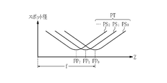
図11Aは、第1の実施形態のOPS60から出力される複数のパルス光PSnのビームウェスト位置wnの変化を計測する方法を説明する模式図である。OPS60の出力光の光路軸上に焦点距離がfの理想レンズ70を配置し、理想レンズ70による出力光の集光位置を計測する。この集光位置がビームウェスト位置に対応する。理想レンズ70とは、収差を無視できる程度のレンズである。集光位置は、図12に示すように、ビームのスポット径が最小となる位置を計測することにより求まる。
図11Aは、第1の実施形態のOPS60から出力される複数のパルス光PSnのビームウェスト位置wnの変化を計測する方法を説明する模式図である。OPS60の出力光の光路軸上に焦点距離がfの理想レンズ70を配置し、理想レンズ70による出力光の集光位置を計測する。この集光位置がビームウェスト位置に対応する。理想レンズ70とは、収差を無視できる程度のレンズである。集光位置は、図12に示すように、ビームのスポット径が最小となる位置を計測することにより求まる。
0周回光PS0は、コリメート光であるので、理想レンズ70による集光位置FP0は、理想レンズ70の焦点位置と一致する。理想レンズ70による1周回光PS1の集光位置FP1は、集光位置FP0より理想レンズ70側に移動する。理想レンズ70による2周回光PS2の集光位置FP2は、集光位置FP1より理想レンズ70側に移動する。以下、同様に、周回数nが多くなるほど、集光位置は理想レンズ70側に近づく。
図11Bは、比較例として説明したOPS40から出力される複数のパルス光PSnのビームウェスト位置wnの計測例を示している。OPS40は、複数のパルス光PSnの進行方向を変化させるので、集光位置FP0,FP1,FP2,・・・は、順にV方向に移動する。
なお、第1の実施形態では、遅延光学系を構成する第1~第4の凹面ミラー62a~62dのうち、第4の凹面ミラー62dの曲率を変えることにより、遅延光学系を非コリメート光学系となるように設定している。第4の凹面ミラー62dに限られず、その他の凹面ミラーの曲率を変えてもよい。
また、遅延光学系を構成する凹面ミラーは4枚に限られない。さらに、曲率を変える凹面ミラーの枚数は1枚に限られない。したがって、遅延光学系を構成する複数の凹面ミラーのうち少なくとも1つの凹面ミラーの曲率を、他の凹面ミラーの曲率と異ならせることにより、遅延光学系を非コリメート光学系とすればよい。
2.5 OPSの変形例
次に、遅延光学系を非コリメート光学系とするためのその他の例について説明する。
次に、遅延光学系を非コリメート光学系とするためのその他の例について説明する。
2.5.1 第1の変形例
図13は、第1の変形例に係るOPS80の構成を示す。OPS80は、ビームスプリッタ81と、第1~第4の凹面ミラー82a~82dと、を含む。ビームスプリッタ81は、比較例のビームスプリッタ11と同一の構成である。
図13は、第1の変形例に係るOPS80の構成を示す。OPS80は、ビームスプリッタ81と、第1~第4の凹面ミラー82a~82dと、を含む。ビームスプリッタ81は、比較例のビームスプリッタ11と同一の構成である。
第1~第4の凹面ミラー82a~82dは、全て同じ曲率半径Rの鏡面を有する。また、第1~第4の凹面ミラー82a~82dは、全て同じ焦点距離Fを有する。OPS80は、第4の凹面ミラー82dの位置が異なること以外は、比較例に係るOPS10と同一の構成である。
図13において、第4の凹面ミラー82dは、破線で示すOPS10の第4の凹面ミラー12dの位置から、遅延光路の光路長LOPSを長くする方向に移動されている。具体的には、第3の凹面ミラー62cと第4の凹面ミラー62dとの間の距離を焦点距離Fの2倍よりも長くし、かつ第4の凹面ミラー62dとビームスプリッタ61との間の距離を焦点距離Fよりも長くする。すなわち、OPS80は、LOPS>8Fの関係を有する。
第1~第4の凹面ミラー82a~82dにより構成される遅延光学系は、非コリメート光学系であるので、遅延光路を周回した周回光は、非コリメート光となる。OPS80から出力される複数のパルス光PSnは、遅延光路の周回数nに応じて、発散角θnが変化するとともに、ビームウェスト位置wnがZ方向に移動する。なお、複数のパルス光PSnの光路軸は、ほぼ同一である。
第1~第4の凹面ミラー82a~82dのうち、光路長LOPSを長くする方向に移動させる凹面ミラーは、第4の凹面ミラー82dに限られず、その他の凹面ミラーであってもよい。遅延光学系を構成する複数の凹面ミラーのうち少なくとも1つの凹面ミラーを、コリメート条件を満たす位置から、遅延光路の光路長を変更する方向に移動させればよい。
2.5.2 第2の変形例
図14は、第2の変形例に係るOPS90の構成を示す。OPS90は、ビームスプリッタ91と、第1~第4の凹面ミラー92a~92dと、第1のレンズ93と、第2のレンズ94と、を含む。ビームスプリッタ91は、比較例のビームスプリッタ11と同一の構成である。第1~第4の凹面ミラー92a~92dは、比較例の第1~第4の凹面ミラー12a~12dと同一の構成であり、かつ同一の位置に配置されている。すなわち、OPS90は、LOPS=8Fの関係を有する。
図14は、第2の変形例に係るOPS90の構成を示す。OPS90は、ビームスプリッタ91と、第1~第4の凹面ミラー92a~92dと、第1のレンズ93と、第2のレンズ94と、を含む。ビームスプリッタ91は、比較例のビームスプリッタ11と同一の構成である。第1~第4の凹面ミラー92a~92dは、比較例の第1~第4の凹面ミラー12a~12dと同一の構成であり、かつ同一の位置に配置されている。すなわち、OPS90は、LOPS=8Fの関係を有する。
第1及び第2のレンズ93,94は、合成石英又はフッ化カルシウム(CaF2)により形成されている。第1のレンズ93は、第2の凹面ミラー92bと第3の凹面ミラー92cとの間の光路上に配置されている。第1のレンズ93は、凹面レンズであり、入射した光の発散角を変更して射出する。第1のレンズ93により、遅延光学系が非コリメート光学系となるように設定される。
第2のレンズ94は、ビームスプリッタ91に入射するパルスレーザ光PLの光路上に配置されている。第2のレンズ94は、凹面レンズであり、第1のレンズ93により変更される発散角を補正するために設けられている。なお、第2のレンズ94は、必須の構成要素ではなく、省略してもよい。
第1~第4の凹面ミラー92a~92d及び第1のレンズ93により構成される遅延光学系は、非コリメート光学系であるので、遅延光路を周回した周回光は、非コリメート光となる。OPS90から出力される複数のパルス光PSnは、遅延光路の周回数nに応じて、発散角θnが変化するとともに、ビームウェスト位置wnがZ方向に移動する。なお、複数のパルス光PSnの光路軸は、ほぼ同一である。
第1のレンズ93は、第2の凹面ミラー92bと第3の凹面ミラー92cとの間の光路上に限られず、第4の凹面ミラー92dとビームスプリッタ91との間の光路上や、ビームスプリッタ91と第1の凹面ミラー92aとの間の光路上に配置してもよい。
第1及び第2のレンズ93,94は、凹面レンズに限られず、その他の光学素子により構成してもよい。例えば、第1及び第2のレンズ93,94は、それぞれシリンドリカルレンズであってもよい。さらに、第1及び第2のレンズ93,94は、それぞれ、湾曲方向が互い直交する2つのシリンドリカルレンズを組み合わせたものであってもよい。
3.第2の実施形態
次に、本開示の第2の実施形態に係るレーザシステムについて説明する。第2の実施形態に係るレーザシステムは、OPSの構成が異なること以外は、図6に示した第1の実施形態に係るレーザシステム50の構成と同一である。第1の実施形態では、OPSを複数の凹面ミラーを含む構成としているが、第2の実施形態では、OPSを、集光レンズを含む構成とする。
次に、本開示の第2の実施形態に係るレーザシステムについて説明する。第2の実施形態に係るレーザシステムは、OPSの構成が異なること以外は、図6に示した第1の実施形態に係るレーザシステム50の構成と同一である。第1の実施形態では、OPSを複数の凹面ミラーを含む構成としているが、第2の実施形態では、OPSを、集光レンズを含む構成とする。
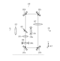
図15は、第2の実施形態に係るレーザシステムに用いられるOPS100の構成を示す。OPS100は、ビームスプリッタ101と、第1~第4の高反射ミラー102a~102dと、第1~第5の集光レンズ103~107と、を含む。ビームスプリッタ101は、第1の実施形態のビームスプリッタ61と同一の構成である。第1~第5の集光レンズ103~107は、それぞれ凸レンズである。
第1及び第2の集光レンズ103,104は、0周回光PS0の発散角θ0を調整するための第1のレンズ群である。第1の集光レンズ103は、固体レーザ装置3から入射したパルスレーザ光PLが、ビームスプリッタ101に入射するまでの光路上に配置されている。第2の集光レンズ104は、パルスレーザ光PLのうち、ビームスプリッタ101を透過した光の光路上に配置されている。
第2の集光レンズ104は、一軸ステージ104aに保持されている。一軸ステージ104aは、第2の集光レンズ104を光路軸方向であるZ方向に移動させることを可能とする。第2の集光レンズ104の光路軸方向に関する位置を調整することにより、0周回光PS0の発散角θ0を調整することができる。
図16Aは、第1及び第2の集光レンズ103,104の位置関係を示している。P1は、第1の集光レンズ103の位置を表している。P2は、第2の集光レンズ104の位置を表している。P0は、ビームスプリッタ101の位置を表している。第1の集光レンズ103の焦点距離をF1、第2の集光レンズ104の焦点距離をF2とする。位置P2は、位置P1と位置P2との間の光路長が「F1+F2」となるように設定されている。すなわち、第1のレンズ群は、コリメート光学系である。なお、位置P2を、コリメート条件を満たす位置からずらすことにより、第1のレンズ群を非コリメート光学系としてもよい。
図15において、第1~第4の高反射ミラー102a~102dと、第3~第5の集光レンズ105~107を含む第2のレンズ群とは、遅延光路を構成している。第1~第4の高反射ミラー102a~102dは、表面に高反射膜が形成された平面ミラーである。第1~第4の高反射ミラー102a~102dの基板は、合成石英又はフッ化カルシウム(CaF2)により形成されている。高反射膜は、誘電体多層膜、例えば、フッ化物を含む膜である。
第1~第4の高反射ミラー102a~102dは、パルスレーザ光PLのうち、ビームスプリッタ101により反射された光を、順に高反射して、再びビームスプリッタ61に入射させるように配置されている。第3及び第4の集光レンズ105,106は、ビームスプリッタ101と第1の高反射ミラー102aとの間に配置されている。第5の集光レンズ107は、第2の高反射ミラー102bと第3の高反射ミラー102cとの間に配置されている。
第4の集光レンズ106は、一軸ステージ106aに保持されている。一軸ステージ104aは、第4の集光レンズ106を光路軸方向であるV方向に移動させることを可能とする。第4の集光レンズ106の光路軸方向に関する位置を調整することにより、n周回光PSn(n≧1)の発散角θnを調整することができる。
図16B及び図17は、第1~第5の集光レンズ103~107の位置関係を示している。P3は、第3の集光レンズ105の位置を表している。P4は、第4の集光レンズ106の位置を表している。P5は、第5の集光レンズ107の位置を表している。第3の集光レンズ105の焦点距離をF3、第4の集光レンズ106の焦点距離をF4、第5の集光レンズ107の焦点距離をF5とする。位置P3は、位置P1と位置P3との間の光路長が「F1+F3」となるように設定されている。
また、P4’は、遅延光路がコリメート条件を満たす場合の第4の集光レンズ106の位置を表している。位置P5は、位置P4’と位置P5との間の光路長が「F4+2F5」となり、位置P2と位置P5との間の光路長が「F2+2F5」となり、位置P3と位置P5との間の光路長が「F3+2F5」となるように設定されている。第4の集光レンズ106は、遅延光学系が非コリメート光学系となるように、すなわち、位置P4が位置P4’からずれた位置となるように、一軸ステージ106aによって光路軸方向に位置調整されている。
また、ビームスプリッタ101と、第1~第4の高反射ミラー102a~102dと、第1~第5の集光レンズ103~107とは、OPS100から出力される0周回光PS0の光路軸と1周回光PS1の光路軸とが一致するように配置されている。すなわち、第2の実施形態では、OPS100から出力される複数のパルス光PSnの光路軸は、全て一致する。
また、図16B及び図17において、LOPSは、遅延光路の光路長を表している。光路長LOPSは、前述の式2の関係を満たしている。また、OPS100により生成される伸長パルスレーザ光PTのパルス幅ΔDTは、前述の式3の関係を満たしている。
3.2 動作
次に、第2の実施形態に係るレーザシステムの動作について説明する。まず、固体レーザ装置3から出力されたパルスレーザ光PLは、第1の集光レンズ103を介してビームスプリッタ101に入射する。ビームスプリッタ101に入射したパルスレーザ光PLのうち一部は、ビームスプリッタ101を透過し、第2の集光レンズ104に入射する。第2の集光レンズ104から出射される光は、0周回光PS0としてOPS100から出力される。図16Aに示すように、0周回光PS0は、コリメート光である。
次に、第2の実施形態に係るレーザシステムの動作について説明する。まず、固体レーザ装置3から出力されたパルスレーザ光PLは、第1の集光レンズ103を介してビームスプリッタ101に入射する。ビームスプリッタ101に入射したパルスレーザ光PLのうち一部は、ビームスプリッタ101を透過し、第2の集光レンズ104に入射する。第2の集光レンズ104から出射される光は、0周回光PS0としてOPS100から出力される。図16Aに示すように、0周回光PS0は、コリメート光である。
ビームスプリッタ101に入射したパルスレーザ光PLのうち、ビームスプリッタ101により反射された反射光は、遅延光路に進入する。遅延光路に進入した反射光は、第3の集光レンズ105、第4の集光レンズ106、第1の高反射ミラー102a、第2の高反射ミラー102b、第5の集光レンズ107、第3の高反射ミラー102c、第4の高反射ミラー102dを経由して、再びビームスプリッタ101に入射する。ビームスプリッタ101に入射した光の一部は、ビームスプリッタ101により反射され第2の集光レンズ104に入射する。第2の集光レンズ104から出射される光は、1周回光PS1としてOPS100から出力される。図16Bに示すように、1周回光PS1は、非コリメート光であり、OPS100から遠くに収束する。すなわち、1周回光PS1のビームウェスト位置w1は、OPS100から遠くに位置する。
ビームスプリッタ101に入射した光のうち、ビームスプリッタ101を透過した透過光は、再び遅延光路に進入し、遅延光路をさらに1回周回して再びビームスプリッタ101に入射する。ビームスプリッタ101に入射した光の一部は、ビームスプリッタ101により反射され、第2の集光レンズ104を介して、2周回光PS2としてOPS100から出力される。図17は、OPS100から出力される2周回光PS2を示す。2周回光PS2のビームウェスト位置w2は、1周回光PS1のビームウェスト位置w1よりもOPS100側に近づく。
この後、光の遅延光路の周回が繰り返されることにより、OPS100からは、3周回光PS3、4周回光PS4、・・・と、順にパルス光が出力される。遅延光路の周回数nが多くなるほど、OPS100からの出力光のビームウェスト位置wnは、OPS100側に近づく。以下の動作は、第1の実施形態に係るレーザシステム50の動作と同様であるので、説明は省略する。
3.3 効果
第2の実施形態に係るレーザシステムは、第1の実施形態と同様に、出力光の可干渉性を低下させるとともに、ASE光の発生を抑制することができる。また、第2の実施形態に係るレーザシステムでは、第2の集光レンズ104及び第4の集光レンズ106の位置を調整することにより、n周回光PSnの発散角θn及びビームウェスト位置wnを調整することができる。
第2の実施形態に係るレーザシステムは、第1の実施形態と同様に、出力光の可干渉性を低下させるとともに、ASE光の発生を抑制することができる。また、第2の実施形態に係るレーザシステムでは、第2の集光レンズ104及び第4の集光レンズ106の位置を調整することにより、n周回光PSnの発散角θn及びビームウェスト位置wnを調整することができる。
なお、第2の実施形態では、0周回光PS0の発散角θ0を調整するために第1のレンズ群を設けているが、第1のレンズ群は、必須の構成要素ではない。遅延光学系を構成する複数の高反射ミラーや集光レンズの配置は、適宜変更可能である。
4.増幅器の後段にOPSを配置する例
第1及び第2の実施形態に係るレーザシステムでは、固体レーザ装置3と増幅器30との間にOPSを配置しているが、さらに増幅器30の後段にOPSを配置してもよい。なお、固体レーザ装置3と増幅器30との間に配置されたOPSが、第1の光学パルスストレッチャに対応する。増幅器の後段に配置されたOPSが、第2の光学パルスストレッチャに対応する。
第1及び第2の実施形態に係るレーザシステムでは、固体レーザ装置3と増幅器30との間にOPSを配置しているが、さらに増幅器30の後段にOPSを配置してもよい。なお、固体レーザ装置3と増幅器30との間に配置されたOPSが、第1の光学パルスストレッチャに対応する。増幅器の後段に配置されたOPSが、第2の光学パルスストレッチャに対応する。
図18は、増幅器30と、増幅器30の後段に配置されたOPS200とを示す斜視図である。OPS200は、ビームスプリッタ201と、第1~第4の凹面ミラー202a~202dと、を含む。OPS200は、図4に示したOPS40と同様の構成である。第1~第4の凹面ミラー202a~202dは、全て同じ曲率半径の鏡面を有する。第1~第4の凹面ミラー202a~202dにより構成される遅延光路の光路長は、焦点距離の8倍である。第4の凹面ミラー202dは、コリメート条件を満たす位置に対して、Z方向を回転軸として僅かに回転させた位置に配置されている。
増幅器30から出力された出力光PAは、OPS200によりH方向に空間的に分解される。OPS200から出力される複数のPAn(n=0,1,2,・・・)は、OPS20内の遅延光路の周回数nに応じて、出射角がH方向に変化する。この結果、レーザシステムからの出力光の可干渉性がさらに低下する。
なお、第4の凹面ミラー202dは、レーザシステムからの出力光が、露光装置の光学系に影響のない範囲で回転させることが好ましい。また、OPS200に代えて、前述のOPS40,60,80,90,100のうちのいずれかを適用してもよい。さらに、増幅器30の後段に、複数のOPSを配置してもよい。例えば、増幅器30の後段に配置したOPS200の後段にOPS40を配置し、増幅器30からの出力光PAを、H方向及びV方向に分解してもよい。
5.増幅器の変形例
第1及び第2の実施形態に係るレーザシステムでは、図6に示される増幅器30を適用しているが、増幅器は、様々な構成を取り得る。
第1及び第2の実施形態に係るレーザシステムでは、図6に示される増幅器30を適用しているが、増幅器は、様々な構成を取り得る。
5.1 第1の変形例
図19は、第1の変形例に係る増幅器300の構成を示す。増幅器300は、図6に示される増幅器30の構成におけるリアミラー33と出力結合ミラー34とに代えて、凹面ミラー310と凸面ミラー320とを備えている。凹面ミラー310と凸面ミラー320とは、伸長パルスレーザ光PTが一対の放電電極32a及び32b間の放電空間35を3回通過して、ビームが拡大されるように配置されている。増幅器300のその他の構成は、増幅器30と同様である。増幅器300は、マルチパス増幅器と称される。
図19は、第1の変形例に係る増幅器300の構成を示す。増幅器300は、図6に示される増幅器30の構成におけるリアミラー33と出力結合ミラー34とに代えて、凹面ミラー310と凸面ミラー320とを備えている。凹面ミラー310と凸面ミラー320とは、伸長パルスレーザ光PTが一対の放電電極32a及び32b間の放電空間35を3回通過して、ビームが拡大されるように配置されている。増幅器300のその他の構成は、増幅器30と同様である。増幅器300は、マルチパス増幅器と称される。
このように、増幅器300を適用する場合には、前述のビームエキスパンダ20を省略することが可能である。
5.2 第2の変形例
図20は、第2の変形例に係る増幅器400の構成を示す。図20において、増幅器400は、レーザチャンバ31と、出力結合ミラー410と、高反射ミラー420~422とを含む。高反射ミラー420~422は、平面ミラーである。さらに、増幅器400は、伸長パルスレーザ光PTを高反射ミラー420に導くための高反射ミラーを含んでもよい。
図20は、第2の変形例に係る増幅器400の構成を示す。図20において、増幅器400は、レーザチャンバ31と、出力結合ミラー410と、高反射ミラー420~422とを含む。高反射ミラー420~422は、平面ミラーである。さらに、増幅器400は、伸長パルスレーザ光PTを高反射ミラー420に導くための高反射ミラーを含んでもよい。
出力結合ミラー410と高反射ミラー420~422とは、リング共振器を構成している。増幅器400では、伸長パルスレーザ光PTは、出力結合ミラー410、高反射ミラー420、放電空間35、高反射ミラー421、高反射ミラー422、放電空間35の順に繰り返し進行して、増幅される。
なお、高反射ミラー420~422を凹面ミラーとし、共振器への入射光が共振器内を周回するたびに発散角が変化するように構成してもよい。この場合、出力結合ミラー410からの出力光は、共振器内の周回数に応じて、ビームウェスト位置が光路軸方向に変化する。このように、増幅器400に、出力光の可干渉性を低下させる機能を持たせることが可能である。
なお、上記各実施形態に係るレーザシステムでは、マスターオシレータとしての固体レーザ装置3を用いているが、マスターオシレータは、固体レーザ装置に限られず、エキシマレーザ装置等、その他のレーザ装置であってもよい。
上記の説明は、制限ではなく単なる例示を意図したものである。従って、添付の特許請求の範囲を逸脱することなく本開示の各実施形態に変更を加えることができることは、当業者には明らかであろう。
本明細書及び添付の特許請求の範囲全体で使用される用語は、「限定的でない」用語と解釈されるべきである。例えば、「含む」又は「含まれる」という用語は、「含まれるものとして記載されたものに限定されない」と解釈されるべきである。「有する」という用語は、「有するものとして記載されたものに限定されない」と解釈されるべきである。また、本明細書及び添付の特許請求の範囲に記載される修飾句「1つの」は、「少なくとも1つ」又は「1又はそれ以上」を意味すると解釈されるべきである。
Claims (15)
- レーザシステムは、以下を備える:
A.パルスレーザ光を出力するレーザ装置;及び
B.前記パルスレーザ光のパルス幅を伸長するための遅延光路を含む第1の光学パルスストレッチャであって、前記遅延光路を周回して出力される周回光のビームウェスト位置を、周回数に応じて光路軸方向に変化させるように構成された第1の光学パルスストレッチャ。 - 請求項1に記載のレーザシステムであって、
前記周回光は、理想レンズで集光した場合に、集光位置が、周回数に応じて光路軸方向に変化する。 - 請求項1に記載のレーザシステムであって、以下をさらに含む:
前記遅延光路は、複数の凹面ミラーにより構成されており、
前記複数の凹面ミラーのうち少なくとも1つの凹面ミラーの曲率が、他の凹面ミラーの曲率と異なる。 - 請求項1に記載のレーザシステムであって、以下をさらに含む:
前記遅延光路は、複数の凹面ミラーにより構成されており、
前記複数の凹面ミラーのうち少なくとも1つの凹面ミラーが、コリメート条件を満たす位置から、前記遅延光路の光路長を変更する方向に移動されている。 - 請求項1に記載のレーザシステムであって、以下をさらに含む:
前記遅延光路は、複数の凹面ミラーにより構成されており、
前記遅延光路には、発散角を変更して出力するレンズが配置されている。 - 請求項1に記載のレーザシステムであって、以下をさらに含む:
前記遅延光路は、複数の高反射ミラーと、複数の集光レンズとにより構成されており、
前記複数の集光レンズのうち少なくとも1つの集光レンズは、コリメート条件を満たす位置から光路軸方向に移動されている。 - 請求項1に記載のレーザシステムであって、
前記遅延光路の光路長が、前記パルスレーザ光の時間的コヒーレント長以上である。 - 請求項1に記載のレーザシステムであって、以下をさらに含む:
C.前記第1の光学パルスストレッチャから出力される伸長パルスレーザ光を増幅する増幅器。 - 請求項8に記載のレーザシステムであって、
前記増幅器は、ファブリペロ共振器またはリング共振器を含む。 - 請求項8に記載のレーザシステムであって、
前記増幅器は、マルチパス増幅器である。 - 請求項8に記載のレーザシステムであって、以下をさらに含む:
D.前記第1の光学パルスストレッチャと前記増幅器との間に配置されたビームエキスパンダ;
ここで、前記ビームエキスパンダは、前記伸長パルスレーザ光のビーム径を、前記増幅器の放電空間の幅に合わせるように拡大する。 - 請求項8に記載のレーザシステムであって、以下をさらに含む:
E.前記増幅器からの出力光のパルス幅を伸長する第2の光学パルスストレッチャ。 - 請求項1に記載のレーザシステムであって、
前記パルスレーザ光のパルス幅をΔD、前記遅延光路の光路長をLOPS、光速をcとした場合に、下式(a)を満たす。
LOPS=c・ΔD ・・・(a) - 請求項8に記載のレーザシステムであって、
前記増幅器は、ファブリペロ共振器であり、
伸長パルスレーザ光のパルス幅をΔDT、前記ファブリペロ共振器の光路長をLamp、光速をcとした場合に、下式(b)を満たす。
ΔDT≧Lamp/c ・・・(b) - 請求項1に記載のレーザシステムであって、
前記レーザ装置は、固体レーザ装置である。
Priority Applications (4)
| Application Number | Priority Date | Filing Date | Title |
|---|---|---|---|
| CN201680086589.9A CN109314365B (zh) | 2016-07-26 | 2016-07-26 | 激光系统 |
| PCT/JP2016/071803 WO2018020564A1 (ja) | 2016-07-26 | 2016-07-26 | レーザシステム |
| JP2018530224A JP6762364B2 (ja) | 2016-07-26 | 2016-07-26 | レーザシステム |
| US16/208,815 US20190103724A1 (en) | 2016-07-26 | 2018-12-04 | Laser system |
Applications Claiming Priority (1)
| Application Number | Priority Date | Filing Date | Title |
|---|---|---|---|
| PCT/JP2016/071803 WO2018020564A1 (ja) | 2016-07-26 | 2016-07-26 | レーザシステム |
Related Child Applications (1)
| Application Number | Title | Priority Date | Filing Date |
|---|---|---|---|
| US16/208,815 Continuation US20190103724A1 (en) | 2016-07-26 | 2018-12-04 | Laser system |
Publications (1)
| Publication Number | Publication Date |
|---|---|
| WO2018020564A1 true WO2018020564A1 (ja) | 2018-02-01 |
Family
ID=61017396
Family Applications (1)
| Application Number | Title | Priority Date | Filing Date |
|---|---|---|---|
| PCT/JP2016/071803 Ceased WO2018020564A1 (ja) | 2016-07-26 | 2016-07-26 | レーザシステム |
Country Status (4)
| Country | Link |
|---|---|
| US (1) | US20190103724A1 (ja) |
| JP (1) | JP6762364B2 (ja) |
| CN (1) | CN109314365B (ja) |
| WO (1) | WO2018020564A1 (ja) |
Cited By (7)
| Publication number | Priority date | Publication date | Assignee | Title |
|---|---|---|---|---|
| WO2021024436A1 (ja) * | 2019-08-07 | 2021-02-11 | ギガフォトン株式会社 | 光学パルスストレッチャー、レーザ装置、及び電子デバイスの製造方法 |
| WO2021171516A1 (ja) * | 2020-02-27 | 2021-09-02 | ギガフォトン株式会社 | パルス幅伸長装置、及び電子デバイスの製造方法 |
| WO2021240682A1 (ja) * | 2020-05-27 | 2021-12-02 | ギガフォトン株式会社 | レーザ装置、パルス幅伸長装置及び電子デバイスの製造方法 |
| US11217962B2 (en) * | 2017-07-13 | 2022-01-04 | Gigaphoton Inc. | Laser system |
| JP2024513761A (ja) * | 2021-04-01 | 2024-03-27 | エーエスエムエル ネザーランズ ビー.ブイ. | レーザシステム |
| JP2024526033A (ja) * | 2021-06-01 | 2024-07-17 | サイマー リミテッド ライアビリティ カンパニー | 光学アセンブリのキャビティ長を能動的に制御するためのシステム |
| WO2025004358A1 (ja) * | 2023-06-30 | 2025-01-02 | ギガフォトン株式会社 | レーザ装置、及び電子デバイスの製造方法 |
Families Citing this family (4)
| Publication number | Priority date | Publication date | Assignee | Title |
|---|---|---|---|---|
| CN115023656A (zh) * | 2020-03-16 | 2022-09-06 | 极光先进雷射株式会社 | 光传输单元、激光装置和电子器件的制造方法 |
| WO2021250844A1 (ja) * | 2020-06-11 | 2021-12-16 | ギガフォトン株式会社 | パルス幅伸長装置、レーザ装置及び電子デバイスの製造方法 |
| JP7496429B2 (ja) * | 2020-10-13 | 2024-06-06 | ギガフォトン株式会社 | ガラスの加工方法 |
| US20230283036A1 (en) * | 2022-03-04 | 2023-09-07 | Lawrence Livermore National Security, Llc | Optical amplifier |
Citations (14)
| Publication number | Priority date | Publication date | Assignee | Title |
|---|---|---|---|---|
| JPH01132186A (ja) * | 1987-11-18 | 1989-05-24 | Toshiba Corp | レーザパルスストレッチャー |
| WO2003021732A1 (en) * | 2001-08-29 | 2003-03-13 | Cymer, Inc. | Laser lithography light source with beam delivery |
| JP2005148550A (ja) * | 2003-11-18 | 2005-06-09 | Gigaphoton Inc | 光学的パルス伸長器および露光用放電励起ガスレーザ装置 |
| JP2006186046A (ja) * | 2004-12-27 | 2006-07-13 | Komatsu Ltd | 光学パルスストレッチ装置およびこれを用いたパルスレーザ装置 |
| WO2006096171A1 (en) * | 2005-03-03 | 2006-09-14 | Coherent, Inc. | Optical pulse duration extender |
| US20060216037A1 (en) * | 2005-03-23 | 2006-09-28 | Wiessner Alexander O | Double-pass imaging pulse-stretcher |
| JP2008135631A (ja) * | 2006-11-29 | 2008-06-12 | Komatsu Ltd | 露光装置用狭帯域レーザ装置 |
| JP2008277617A (ja) * | 2007-05-01 | 2008-11-13 | Gigaphoton Inc | 光学的パルスストレッチ装置及び露光用放電励起レーザ装置 |
| JP2009076906A (ja) * | 2007-09-24 | 2009-04-09 | Schott Ag | レーザパルス長変更方法及び装置 |
| JP2009532864A (ja) * | 2006-03-31 | 2009-09-10 | サイマー インコーポレイテッド | 共焦点パルス伸長器 |
| JP2010003755A (ja) * | 2008-06-18 | 2010-01-07 | Mitsubishi Electric Corp | 波長変換レーザ装置 |
| JP2011192849A (ja) * | 2010-03-15 | 2011-09-29 | Gigaphoton Inc | レーザ装置 |
| JP2012015445A (ja) * | 2010-07-05 | 2012-01-19 | Japan Steel Works Ltd:The | レーザアニール処理装置およびレーザアニール処理方法 |
| JP2013214708A (ja) * | 2012-03-30 | 2013-10-17 | Gigaphoton Inc | レーザ装置、レーザシステムおよび極端紫外光生成装置 |
Family Cites Families (19)
| Publication number | Priority date | Publication date | Assignee | Title |
|---|---|---|---|---|
| JPH0473983A (ja) * | 1990-07-16 | 1992-03-09 | Toshiba Corp | レーザパルスストレッチャー |
| JP2554772B2 (ja) * | 1990-10-11 | 1996-11-13 | 株式会社東芝 | レーザパルスストレッチャー |
| US7916388B2 (en) * | 2007-12-20 | 2011-03-29 | Cymer, Inc. | Drive laser for EUV light source |
| US6928093B2 (en) * | 2002-05-07 | 2005-08-09 | Cymer, Inc. | Long delay and high TIS pulse stretcher |
| US7518787B2 (en) * | 2006-06-14 | 2009-04-14 | Cymer, Inc. | Drive laser for EUV light source |
| JP2005303135A (ja) * | 2004-04-14 | 2005-10-27 | Canon Inc | 明光学装置およびそれを用いた投影露光装置 |
| US7564888B2 (en) * | 2004-05-18 | 2009-07-21 | Cymer, Inc. | High power excimer laser with a pulse stretcher |
| EP2204695B1 (en) * | 2008-12-31 | 2019-01-02 | ASML Holding N.V. | Etendue adjuster for a pulsed beam |
| US8416396B2 (en) * | 2010-07-18 | 2013-04-09 | David H. Parker | Methods and apparatus for optical amplitude modulated wavefront shaping |
| JP2012199425A (ja) * | 2011-03-22 | 2012-10-18 | Gigaphoton Inc | マスタオシレータ、レーザシステム、およびレーザ生成方法 |
| JP5844535B2 (ja) * | 2011-03-28 | 2016-01-20 | ギガフォトン株式会社 | レーザシステムおよびレーザ生成方法 |
| JP5844536B2 (ja) * | 2011-03-28 | 2016-01-20 | ギガフォトン株式会社 | レーザシステムおよびレーザ生成方法 |
| US8724203B2 (en) * | 2011-12-12 | 2014-05-13 | Corning Incorporated | Variable pulse stretching length by variable beamsplitter reflectivity |
| JP6348121B2 (ja) * | 2013-12-16 | 2018-06-27 | ギガフォトン株式会社 | レーザ装置 |
| CN104319615B (zh) * | 2014-11-02 | 2017-12-26 | 中国科学院光电技术研究所 | 一种基于双分束元件的准分子激光脉冲展宽装置 |
| WO2016147308A1 (ja) * | 2015-03-16 | 2016-09-22 | 国立大学法人九州大学 | レーザシステム及びレーザアニール装置 |
| JPWO2017163356A1 (ja) * | 2016-03-24 | 2019-01-31 | 国立大学法人九州大学 | レーザドーピング装置及び半導体装置の製造方法 |
| JP6920354B2 (ja) * | 2017-01-26 | 2021-08-18 | ギガフォトン株式会社 | レーザシステム |
| WO2018229854A1 (ja) * | 2017-06-13 | 2018-12-20 | ギガフォトン株式会社 | レーザ装置及び光学素子の製造方法 |
-
2016
- 2016-07-26 CN CN201680086589.9A patent/CN109314365B/zh active Active
- 2016-07-26 JP JP2018530224A patent/JP6762364B2/ja active Active
- 2016-07-26 WO PCT/JP2016/071803 patent/WO2018020564A1/ja not_active Ceased
-
2018
- 2018-12-04 US US16/208,815 patent/US20190103724A1/en not_active Abandoned
Patent Citations (14)
| Publication number | Priority date | Publication date | Assignee | Title |
|---|---|---|---|---|
| JPH01132186A (ja) * | 1987-11-18 | 1989-05-24 | Toshiba Corp | レーザパルスストレッチャー |
| WO2003021732A1 (en) * | 2001-08-29 | 2003-03-13 | Cymer, Inc. | Laser lithography light source with beam delivery |
| JP2005148550A (ja) * | 2003-11-18 | 2005-06-09 | Gigaphoton Inc | 光学的パルス伸長器および露光用放電励起ガスレーザ装置 |
| JP2006186046A (ja) * | 2004-12-27 | 2006-07-13 | Komatsu Ltd | 光学パルスストレッチ装置およびこれを用いたパルスレーザ装置 |
| WO2006096171A1 (en) * | 2005-03-03 | 2006-09-14 | Coherent, Inc. | Optical pulse duration extender |
| US20060216037A1 (en) * | 2005-03-23 | 2006-09-28 | Wiessner Alexander O | Double-pass imaging pulse-stretcher |
| JP2009532864A (ja) * | 2006-03-31 | 2009-09-10 | サイマー インコーポレイテッド | 共焦点パルス伸長器 |
| JP2008135631A (ja) * | 2006-11-29 | 2008-06-12 | Komatsu Ltd | 露光装置用狭帯域レーザ装置 |
| JP2008277617A (ja) * | 2007-05-01 | 2008-11-13 | Gigaphoton Inc | 光学的パルスストレッチ装置及び露光用放電励起レーザ装置 |
| JP2009076906A (ja) * | 2007-09-24 | 2009-04-09 | Schott Ag | レーザパルス長変更方法及び装置 |
| JP2010003755A (ja) * | 2008-06-18 | 2010-01-07 | Mitsubishi Electric Corp | 波長変換レーザ装置 |
| JP2011192849A (ja) * | 2010-03-15 | 2011-09-29 | Gigaphoton Inc | レーザ装置 |
| JP2012015445A (ja) * | 2010-07-05 | 2012-01-19 | Japan Steel Works Ltd:The | レーザアニール処理装置およびレーザアニール処理方法 |
| JP2013214708A (ja) * | 2012-03-30 | 2013-10-17 | Gigaphoton Inc | レーザ装置、レーザシステムおよび極端紫外光生成装置 |
Cited By (11)
| Publication number | Priority date | Publication date | Assignee | Title |
|---|---|---|---|---|
| US11217962B2 (en) * | 2017-07-13 | 2022-01-04 | Gigaphoton Inc. | Laser system |
| WO2021024436A1 (ja) * | 2019-08-07 | 2021-02-11 | ギガフォトン株式会社 | 光学パルスストレッチャー、レーザ装置、及び電子デバイスの製造方法 |
| US11837839B2 (en) | 2019-08-07 | 2023-12-05 | Gigaphoton Inc. | Optical pulse stretcher, laser device, and electronic device manufacturing method |
| WO2021171516A1 (ja) * | 2020-02-27 | 2021-09-02 | ギガフォトン株式会社 | パルス幅伸長装置、及び電子デバイスの製造方法 |
| CN114902143A (zh) * | 2020-02-27 | 2022-08-12 | 极光先进雷射株式会社 | 脉冲宽度扩展装置和电子器件的制造方法 |
| US12038567B2 (en) | 2020-02-27 | 2024-07-16 | Gigaphoton Inc. | Pulse width expansion apparatus and electronic device manufacturing method |
| CN114902143B (zh) * | 2020-02-27 | 2025-10-21 | 极光先进雷射株式会社 | 脉冲宽度扩展装置和电子器件的制造方法 |
| WO2021240682A1 (ja) * | 2020-05-27 | 2021-12-02 | ギガフォトン株式会社 | レーザ装置、パルス幅伸長装置及び電子デバイスの製造方法 |
| JP2024513761A (ja) * | 2021-04-01 | 2024-03-27 | エーエスエムエル ネザーランズ ビー.ブイ. | レーザシステム |
| JP2024526033A (ja) * | 2021-06-01 | 2024-07-17 | サイマー リミテッド ライアビリティ カンパニー | 光学アセンブリのキャビティ長を能動的に制御するためのシステム |
| WO2025004358A1 (ja) * | 2023-06-30 | 2025-01-02 | ギガフォトン株式会社 | レーザ装置、及び電子デバイスの製造方法 |
Also Published As
| Publication number | Publication date |
|---|---|
| JP6762364B2 (ja) | 2020-09-30 |
| CN109314365A (zh) | 2019-02-05 |
| CN109314365B (zh) | 2021-05-11 |
| US20190103724A1 (en) | 2019-04-04 |
| JPWO2018020564A1 (ja) | 2019-05-09 |
Similar Documents
| Publication | Publication Date | Title |
|---|---|---|
| WO2018020564A1 (ja) | レーザシステム | |
| US11682877B2 (en) | Laser system | |
| US9711934B2 (en) | Laser apparatus | |
| JPWO2019012642A1 (ja) | レーザシステム | |
| WO2016189722A1 (ja) | レーザ装置及び狭帯域化光学系 | |
| CN114902143B (zh) | 脉冲宽度扩展装置和电子器件的制造方法 | |
| US12542412B2 (en) | Gas laser device and electronic device manufacturing method | |
| WO2017029729A1 (ja) | レーザ装置 | |
| CN115039298B (zh) | 激光装置和电子器件的制造方法 | |
| US20170149199A1 (en) | Laser device | |
| US11870209B2 (en) | Laser system and electronic device manufacturing method | |
| US11837839B2 (en) | Optical pulse stretcher, laser device, and electronic device manufacturing method | |
| CN115485937B (zh) | 脉冲宽度扩展装置、激光装置和电子器件的制造方法 | |
| JP2006203008A (ja) | 2ステージレーザシステム | |
| JP2013214707A (ja) | 透過型光学素子、レーザチャンバ、増幅段レーザ、発振段レーザ、およびレーザ装置 | |
| US20260072288A1 (en) | Laser system and method for manufacturing electronic device | |
| JP7784444B2 (ja) | パルス伸張器及び電子デバイスの製造方法 | |
| US20250246864A1 (en) | Laser apparatus and electronic device manufacturing method | |
| US20210288459A1 (en) | Laser system and electronic device manufacturing method | |
| WO2017046860A1 (ja) | レーザシステム |
Legal Events
| Date | Code | Title | Description |
|---|---|---|---|
| ENP | Entry into the national phase |
Ref document number: 2018530224 Country of ref document: JP Kind code of ref document: A |
|
| 121 | Ep: the epo has been informed by wipo that ep was designated in this application |
Ref document number: 16910467 Country of ref document: EP Kind code of ref document: A1 |
|
| NENP | Non-entry into the national phase |
Ref country code: DE |
|
| 122 | Ep: pct application non-entry in european phase |
Ref document number: 16910467 Country of ref document: EP Kind code of ref document: A1 |