WO2018016408A1 - 質量分析装置 - Google Patents
質量分析装置 Download PDFInfo
- Publication number
- WO2018016408A1 WO2018016408A1 PCT/JP2017/025505 JP2017025505W WO2018016408A1 WO 2018016408 A1 WO2018016408 A1 WO 2018016408A1 JP 2017025505 W JP2017025505 W JP 2017025505W WO 2018016408 A1 WO2018016408 A1 WO 2018016408A1
- Authority
- WO
- WIPO (PCT)
- Prior art keywords
- electrode system
- mass spectrometer
- auxiliary electrode
- multipole
- rod
- Prior art date
- Legal status (The legal status is an assumption and is not a legal conclusion. Google has not performed a legal analysis and makes no representation as to the accuracy of the status listed.)
- Ceased
Links
Images








Classifications
-
- H—ELECTRICITY
- H01—ELECTRIC ELEMENTS
- H01J—ELECTRIC DISCHARGE TUBES OR DISCHARGE LAMPS
- H01J49/00—Particle spectrometers or separator tubes
- H01J49/26—Mass spectrometers or separator tubes
- H01J49/34—Dynamic spectrometers
- H01J49/42—Stability-of-path spectrometers, e.g. monopole, quadrupole, multipole, farvitrons
Definitions
- the present invention relates to a mass spectrometer using a multipole electric field.
- Patent Document 1 Japanese Patent Laid-Open No. 3-236149 discloses a quadrupole electrode system composed of four electrode rods supported in parallel with each other, and an electrode And an auxiliary electrode system comprising an auxiliary electrode bar provided at at least one end of the bar, and a voltage ( ⁇ (U + Vcos ⁇ t)) obtained by superimposing a DC voltage U and a high-frequency AC voltage (Vcos ⁇ t) on the electrode bar.
- a quadrupole mass spectrometer that performs mass separation of ions introduced into an electric field along the axial direction of the quadrupole is disclosed.
- the mass spectrometer is desired to be downsized as one of the measures for dealing with various usage environments.
- Miniaturization of mass spectrometers requires miniaturization of electrodes that occupy a certain percentage of the apparatus, but if the electrode rod is simply shortened, the length of the electric field acting on the target ions in ion separation will also be shortened. Therefore, there is a problem that the resolution in the mass spectrometer is lowered.
- the present invention has been made in view of the above, and an object of the present invention is to provide a mass spectrometer capable of downsizing the apparatus while suppressing a decrease in resolution.
- the present invention provides a multipole electrode system composed of 2n (n is an integer of 2 or more) rod-like electrodes arranged parallel to each other on a virtual cylinder, and the multipole electrode system.
- An auxiliary electrode system comprising a plurality of rod-like electrodes arranged at at least one end of the electrode and corresponding to each of the plurality of rod-like electrodes constituting the multipole electrode system, and the multipole electrode system and the auxiliary electrode system
- a voltage control unit for applying a DC voltage and a high-frequency voltage, respectively, and the multiplexing is greater than a ratio of the magnitude of the amplitude of the high-frequency voltage applied to the auxiliary electrode system to the radius of the virtual inscribed cylinder of the auxiliary electrode system. It is assumed that the ratio of the magnitude of the amplitude of the high-frequency voltage applied to the multipole electrode system to the radius of the virtual inscribed cylinder of the pole electrode system is increased.
- FIG. 6 is a diagram showing the stability of the flight trajectory of reagent ions in the x-axis direction and the y-axis direction on the aq plane. It is a figure which expands and shows the principal part in FIG. It is a figure which shows an example of mass spectral data. It is a simulation result which shows the relationship between the frequency
- FIG. 1 is a diagram schematically showing an overall configuration of a mass spectrometer according to the present embodiment.
- a mass spectrometer 11 includes a preprocessing unit 1, an ionization unit 2, an ion transport unit 3, a mass analysis unit 4, an ion detection unit 5, a data processing unit (CPU) 6, a control unit 7, and a voltage control unit 8. , A user input unit 9, a display unit 10, and a storage unit 13.
- the pretreatment unit 1 performs pretreatment on a sample to be subjected to mass spectrometry, and temporally separates and fractionates the sample, for example, gas chromatography (GC: Gas ⁇ Chromatography) or liquid chromatography (LC: Liquid Chromatography) is used.
- GC Gas ⁇ Chromatography
- LC liquid chromatography
- the sample pretreated in the pretreatment unit 1 is sequentially ionized, and the ionized sample (sample ion) is transported by the ion transport unit 3 and incident on the mass analysis unit 4.
- the mass analysis unit 4 is based on the principle of separating sample ions for each ion species by the action of an electric field generated by applying a DC voltage or a high-frequency voltage to the multipole electrode system.
- the sample ions (sample ion beam) incident from the side) are separated according to the mass-to-charge ratio (m / Z) for each ion species, and ion species having a specific range of mass-to-charge ratio pass through the mass analyzer 4. Then, it is ejected from the downstream side (exit side) to the ion detector 5.
- m in the mass-to-charge ratio represents the ion mass
- Z represents the number of charged ions of the ion.
- sample ions of the ion species that have passed through the mass analysis unit 4 are detected, and the detection result is sent to the data processing unit (CPU) 6, for example, detection for each mass to charge ratio (m / Z).
- the data representing the intensity is processed and sent to the control unit 7.
- the control unit 7 controls the overall operation of the mass spectrometer 11. For example, the control unit 7 controls the operation of the voltage control unit 8 based on the input content to the user input unit 9, the data sent from the data processing unit 6, and the like. In addition, the control unit 7 displays the data sent from the data processing unit 6 on the display unit 10. Information related to the control of the mass spectrometer 11 such as various settings input via the user input unit 9, data from the data processing unit 6, various programs and mathematical formulas is stored in the storage unit 13.
- the voltage control unit 8 controls a DC voltage and a high frequency voltage applied to a plurality of rod-shaped electrodes (described later) constituting the mass analysis unit 4 based on an instruction from the control unit 7.
- a voltage source 12 that generates a voltage based on the instruction is included.
- FIG. 2 is a diagram schematically showing an enlarged mass spectrometer in FIG. 3 is a cross-sectional view at position A on a plane perpendicular to the longitudinal direction of the rod-shaped electrode of FIG. 1
- FIG. 4 is a cross-sectional view at position B, and FIG. 1 to 5, coordinates having a z-axis in the downstream direction along the rod-shaped electrode, a y-axis in the upward direction in FIG. 1, and an x-axis in the front direction in FIG. 1 in the center of the space surrounded by the rod-shaped electrodes. Set the system.
- the mass spectrometer 4 includes a multipole electrode system composed of 2n (n is an integer of 2 or more) rod-like electrodes arranged in parallel with each other on a virtual cylinder, and a multipole electrode system.
- An auxiliary electrode system composed of a plurality of rod-shaped electrodes arranged corresponding to each of the rod-shaped electrodes constituting the multipole electrode system at the end (upstream side) on which the sample ions are incident, and the multipole electrode system
- an auxiliary electrode system composed of a plurality of rod-like electrodes arranged to correspond to each of the rod-like electrodes constituting the multipole electrode system at the end (downstream side) where the sample ions are ejected.
- a multipole electrode system composed of four rod-shaped electrodes will be described as an example of a multipole electrode system.
- An apparatus using a multipole electrode system composed of four rod-like electrodes as described above is particularly called a quadrupole mass spectrometer (QMS).
- QMS quadrupole mass spectrometer
- the mass analyzing unit 4 in the present embodiment includes a quadrupole electrode system 41 including four rod-like electrodes 41a to 41d arranged in parallel with each other on a virtual cylinder, and a quadrupole electrode system.
- 41 is composed of a plurality of rod-shaped electrodes 42a to 42d arranged to correspond to the rod-shaped electrodes 41a to 41d constituting the quadrupole electrode system 41 at the end (upstream side) on which the sample ions are incident.
- the first auxiliary electrode system 42 and the rod-shaped electrodes 41a to 41d constituting the quadrupole electrode system 41 correspond to the ends of the quadrupole electrode system 41 on the side where sample ions are ejected (downstream side).
- the second auxiliary electrode system 43 is composed of a plurality of rod-shaped electrodes 43a to 43d arranged to do so.
- An inlet electrode 40 a is provided on the upstream side of the first auxiliary electrode system 42, and an outlet electrode 40 b is provided on the downstream side of the second auxiliary electrode system 43.
- the rod-like electrodes 41a to 41d of the quadrupole electrode system 41 are formed to have the same length, and are arranged so that the longitudinal direction thereof is along the z-axis and the position in the z-axis direction is the same.
- the rod-like electrodes 42a to 42d of the first auxiliary electrode system 42 are formed to have the same length, and are arranged so that the longitudinal direction thereof is along the z-axis and the position in the z-axis direction is the same.
- the rod-shaped electrodes 43a to 43d of the second auxiliary electrode system 43 are formed to have the same length, and are arranged so that the longitudinal direction thereof is along the z-axis and the position in the z-axis direction is the same. Yes.
- the quadrupole electrode system 41 and the first and second auxiliary electrode systems 42 and 43 are configured by using cylindrical rod-shaped electrodes.
- a space surrounded by the rod-shaped electrodes An electrode having a hyperboloid shape along the surface of the rod-shaped electrode on the side (the side through which sample ions pass) can be used instead of the rod-shaped electrode.
- the rod-shaped electrodes 41a to 41d constituting the quadrupole electrode system 41, when the rod-shaped electrodes arranged at positions facing each other across the space surrounded by the rod-shaped electrodes 41a to 41d, ie, the rod-shaped electrodes 41a, 41a, 41d, 41c and rod-shaped electrodes 41b and 41d, respectively, a voltage ⁇ main in which a direct current voltage and a high-frequency voltage expressed by the following (formula 1) are applied to the rod-shaped electrodes 41a and 41c, and the rod-shaped electrodes 41b and 41c A voltage (- ⁇ main) obtained by superimposing a DC voltage and a high-frequency voltage as represented by the following (formula 2) is applied to 41d.
- the voltage (Formula 1) applied to the rod-shaped electrodes 41a and 41c and the voltage (Formula 2) applied to the rod-shaped electrodes 41b and 41d are in opposite phases.
- r0 is a half value of the distance between a pair of opposing rod electrodes, that is, the radius of the virtual inscribed cylinder of the rod electrodes 41a to 41d of the quadrupole electrode system 41. .
- a virtual inscribed cylinder of the rod-shaped electrodes 41a to 41d is indicated by a line 40c.
- the sample ions transported by the ion transport unit 3 are incident on the center of the quadrupole electrode system 41 along the z axis, and pass through the electric fields Ex and Ey formed by the above (Expression 3) and (Expression 4). Will do.
- the stability in the x-axis direction and y-axis direction of the flight activation of the sample ions is derived from a motion equation (Mathieu equation) representing the motion state of the ions (sample ions) between the rod-shaped electrodes, and the dimensionless parameters a, It is obtained by q (see (Expression 5) and (Expression 6) below).
- the dimensionless parameters (a, q) shown in (Equation 5) and (Equation 6) are stability parameters in a quadrupole mass spectrometer (QMS), and r0 is a distance between a pair of opposing rod-shaped electrodes.
- E is the elementary charge
- m / Z is the mass-to-charge ratio of the ions
- U is the DC voltage applied to the rod-shaped electrodes 41a to 41d
- VRF is the amplitude of the high-frequency voltage applied to the rod-shaped electrodes 41a to 41d
- ⁇ RF is This is the angular vibration frequency of the high-frequency voltage applied to the rod-shaped electrodes 41a to 41d.
- FIG. 6 is a diagram showing the stability of the flight trajectory of reagent ions in the x-axis direction and the y-axis direction on the aq plane.
- FIG. 7 is an enlarged view showing a main part in FIG.
- the stability parameters (a, q) in the sample ions incident on the quadrupole electrode system 41 are ion species (mass-to-charge ratio m / Z), radius r0, DC voltage U, amplitude VRF, angular vibration frequency ⁇ RF, and the like. A point on the aq plane shown in FIG. 5 is taken according to the value.
- the stability parameters (a, q) are expressed by the following (Expression 7). The value of any point on the straight line (scan line 14) to be taken is taken. At this time, the stability parameters (a, q) have different points on the scanning line 14 according to the mass-to-charge ratio m / Z of each ion species.
- the stabilization parameter (a, q) takes a value in the region of “x, y: stable” (stable transmission region)
- the ionic species (sample ions) corresponding to the condition are obtained from the quadrupole electrode system 41. While oscillating, the light penetrates stably in the z-axis direction and reaches the ion detector 5.
- the stabilization parameter (a, q) takes a value in the region of “x, y: unstable”, “x: stable, y: unstable”, or “x: unstable, y: stable”.
- the ion species (sample ions) corresponding to the conditions cannot be transmitted stably because the vibration in the xy plane direction diverges in the quadrupole electrode system 41, and the side of the quadrupole electrode system 41 (In the direction along the xy plane) is emitted (unstable emission).
- sample ions having a specific mass-to-charge ratio m / Z are allowed to pass through to be detected by the ion detector 5 and other ions having a mass-to-charge ratio m / Z are detected.
- seeds seed (sample ions) out of the quadrupole electrode system 41 (unstable radiation)
- specific ion species in the sample ions can be separated and detected.
- FIG. 7 which is an enlarged view of the main part 15 of FIG. 6, only the ion species whose stability parameter (a, q) is indicated by the point M on the scanning line 14 and the inclination of the scanning line 14 is stable. And other ion species (for example, ion species that take the stability parameters (a, q) of the point (M + 1) and the point (M-1) adjacent to the point M on the scanning line 14).
- a voltage ⁇ e in which a direct current voltage and a high-frequency voltage expressed by the following (formula 8) are applied is applied to the rod-shaped electrodes 42a and 42c.
- a voltage ( ⁇ e) obtained by superimposing a DC voltage and a high-frequency voltage as represented by the following (formula 9) is applied to 42b and 42d.
- the voltage (Formula 8) applied to the rod-shaped electrodes 42a and 42c and the voltage (Formula 9) applied to the rod-shaped electrodes 42b and 42d are in opposite phases.
- the rod-shaped electrodes 43a and 43c are voltages in which a DC voltage and a high-frequency voltage expressed by (Equation 8) are superimposed. ⁇ e is applied, and a voltage ( ⁇ e) obtained by superimposing a DC voltage and a high-frequency voltage as represented by (Equation 9) is applied to the rod-shaped electrodes 43b and 43d.
- the mass to charge ratio m / Z is different from each other in natural frequency, and it vibrates with a stable amplitude to fly to the downstream end of the multipole electrode system. Mass separation is performed using the principle that there is an ion species having a mass-to-charge ratio of m / Z ejected outside the electrode system.
- the inventors focused on the possibility that the number of oscillations of the sample ions when passing through the inside of the quadrupole electrode system 41 affects the resolution, and passed through the quadrupole electrode system 41. If the number of vibrations is small, the difference in vibration frequency (natural frequency) between adjacent ion species does not sufficiently affect mass separation from the viewpoint of the mass-to-charge ratio m / Z for each ion species. It was thought that the separation of the ion species to be adjacent to the adjacent ion species was insufficient and the mass peak spread, in other words, the resolution was lowered.
- FIG. 9 is a simulation result showing the relationship between the number of oscillations of sample ions passing through the quadrupole electrode system and the resolution.
- the vertical axis represents the half width ( ⁇ M) of the mass spectrum
- the horizontal axis represents the number of vibrations (times) when the sample ions pass through the quadrupole electrode system.
- FIG. 9 shows that the half width of the mass spectrum shown on the vertical axis can be seen as an index directly related to the resolution (M / ⁇ M). That is, FIG. 9 shows that the number of vibrations of the sample ions when passing through the quadrupole electrode system 41 greatly affects the resolution, and the resolution (M / ⁇ M) increases as the number of vibrations increases.
- FIG. 10 is a diagram showing a simulation result of potential potential in a single quadrupole electrode system.
- a potential potential is formed in the quadrupole electrode system 41 according to the voltage (DC voltage, high frequency voltage) applied to the rod-shaped electrodes 41a to 41d. From FIG. 10, it can be seen that a constant potential is formed at the center of the quadrupole electrode system 41, and the potential decreases toward the ends at both ends of the quadrupole electrode system 41. Recognize. Then, it can be considered that when the potential potential formed in this way is a certain level or more, it effectively affects the motion state of the sample ions passing through the quadrupole electrode system 41.
- FIG. 11 is an explanatory diagram of the execution length of the potential potential.
- the error ( ⁇ r / r0) may represent an assembly error of the quadrupole electrode system, but in the present embodiment, it is not an assembly error of the actual quadrupole electrode system, but a quadrupole electrode system (assembly error).
- the error (distortion) of the electric field formed inside is also converted into the assembly error of the quadrupole electrode system. That is, since the electric field distortion (end distortion Ld) is large at the end of the quadrupole electrode system, the error ( ⁇ r / r0) is larger than the actual assembly error.
- the definition of the effective length is not limited to the above, and the effective length is calculated by calculating a range that is assumed to act effectively on the motion state of the sample ions passing through the quadrupole electrode system 41 from other reasons. May be defined as long. That is, the length in the z-axis direction of the region where an electric field (quadrupole electric field) is formed inside the quadrupole electrode system 41 particularly effectively acts on the separation of sample ions (ie contributes to resolution).
- the effective length may be determined by pointing to the length of the highly accurate electric field that is considered to be.
- the longer the effective length of the potential potential that is, the longer the distance that effectively acts on the sample ions, the greater the number of oscillations. I can say that.
- the decrease in effective length can be suppressed, it can be said that the decrease in resolution can also be suppressed.
- the present invention is based on the inventor's new knowledge that the resolution of a mass spectrometer using a multipole electrode system is affected by the effective length of the potential potential through which sample ions pass.
- the mass spectrometer 4 and The voltage control unit 8 (control unit 7) is configured, and it is necessary to suppress a decrease in potential potential at the end of the quadrupole electrode system 41 including the auxiliary electrode systems 42 and 43.
- the virtual inscribed cylinder of the quadrupole electrode system 41 is larger than the ratio of the amplitude Ve of the high frequency voltage applied to the auxiliary electrode systems 42 and 43 to the radius re of the virtual inscribed cylinder of the auxiliary electrode systems 42 and 43. It is necessary to configure so that the ratio of the magnitude of the amplitude VRF of the high-frequency voltage applied to the quadrupole electrode system 41 with respect to the radius r0 is large.
- the mass analyzer 4 and the voltage control unit 8 are configured and controlled so as to satisfy the following (formula 11) to (formula 14), so that the mass (formula 10) is satisfied.
- the analyzer 11 is configured.
- the mass analyzing unit 4 is configured such that the radius r0 of the virtual inscribed cylinder of the quadrupole electrode system 41 and the radius re of the virtual inscribed cylinder of the auxiliary electrode systems 42 and 43 are the same. And voltages (DC voltage and high frequency voltage) are applied to the quadrupole electrode system 41 and the auxiliary electrode systems 42 and 43 so as to satisfy (Equation 12) to (Equation 14).
- FIG. 12 is a diagram showing a simulation result of the potential potential in the mass spectrometer in the present embodiment.
- miniaturization is desired as one of the measures for dealing with various usage environments.
- the miniaturization of mass spectrometers requires the miniaturization of electrodes that occupy a certain proportion of the apparatus.
- the electrode rod (rod-shaped electrode) is simply shortened, the electric field acting on the target ions in the separation of ions is reduced. Since the length is also shortened, there is a problem that the resolution in the mass spectrometer is lowered.
- a quadrupole electrode system 41 composed of four rod-like electrodes 41a to 41d arranged in parallel with each other on a virtual cylinder, and at least one end of the quadrupole electrode system 41
- Auxiliary electrode systems 42, 43 composed of a plurality of rod-shaped electrodes 42 a-42 d, 43 a-43 d disposed to correspond to each of the plurality of rod-shaped electrodes 41 a-41 d constituting the quadrupole electrode system 41.
- a voltage control unit 8 for applying a DC voltage and a high-frequency voltage to the quadrupole electrode system 41 and the auxiliary electrode systems 42 and 43, respectively, and the auxiliary electrode for the radius re of the virtual inscribed cylinder of the auxiliary electrode systems 42 and 43
- the high-frequency voltage applied to the quadrupole electrode system 41 with respect to the radius r0 of the virtual inscribed cylinder of the quadrupole electrode system 41 is larger than the ratio of the magnitude Ve of the high-frequency voltage applied to the systems 42 and 43.
- the ratio of the size of the width VRF is configured to be large, a decrease in potential potential at the end of the quadrupole electrode system 41 including the auxiliary electrode systems 42 and 43 can be suppressed, and the quadrupole electrode system can be suppressed.
- the effective length can be extended without extending the physical length of the electrode system 41 and the auxiliary electrode systems 42 and 43.
- the rod-shaped electrode is downsized (shortened) when the mass spectrometer is downsized, the effective length of the potential potential can be extended, so the mass spectrometer can be downsized while suppressing a decrease in resolution. You can plan.
- the effective length of the potential potential can be extended, so that the resolution can be improved without extending the physical length of the electrode system.
- the potentials of the first and second auxiliary electrode systems 42 and 43 in the first embodiment are made different between the first auxiliary electrode system 42 and the second auxiliary electrode system 43.
- each variable of (Equation 8) to (Equation 14) shown for the first and second auxiliary electrode systems 42 and 43 in the first embodiment is read as e1.
- This is applied to the first auxiliary electrode system 42 of the modified example, and the subscript e of each variable in (Equation 8) to (Equation 14) is read as e2 and applied to the second auxiliary electrode system 43 of the modified example.
- are the subscript e in each variable of (Equation 8) to (Equation 14) shown for the first and second auxiliary electrode systems 42 and 43 in the first embodiment.
- This embodiment is a case where (Equation 15) is used instead of (Equation 11) in order to achieve (Equation 10) in the first embodiment.
- FIG. 13 is a diagram schematically showing an enlarged mass spectrometer in the present embodiment.
- the same members as those in the first embodiment are denoted by the same reference numerals, and description thereof is omitted.
- the mass analyzer 4 and the voltage control unit 8 are configured and controlled so as to satisfy the following (formula 15) to (formula 18), so that the mass (formula 10) is satisfied.
- the analyzer 11 is configured.
- the mass spectrometric unit 4 is set so that the radius re of the virtual inscribed cylinders of the auxiliary electrode systems 42A and 43A is smaller than the radius r0 of the virtual inscribed cylinder of the quadrupole electrode system 41. Then, voltages (DC voltage and high frequency voltage) are applied to the quadrupole electrode system 41 and the auxiliary electrode systems 42A and 43A so as to satisfy (Equation 16) to (Equation 18).
- the quadrupole electrode system 41 and the first and second auxiliary electrode systems 42A and 43A are integrated.
- the quadrupole electrode system 41A can be configured.
- the auxiliary electrode system parts 421A and 431A function as the auxiliary electrode systems 42A and 43A.
- the type of voltage applied to the electrode system is Since the number of power supplies can be reduced, the voltage can be controlled more easily and the cost can be reduced.
- the manufacturing accuracy of the electrode system can be improved by integrally configuring the electrode system.
- This modification shows a case where the auxiliary electrode system is used only on the emission side (downstream side) of the quadrupole electrode system in the first and second embodiments.
- FIGS. 15 to 17 are diagrams schematically showing an enlarged mass analysis unit in the present modification.
- FIG. 15 shows the first embodiment
- FIGS. 16 and 17 show the second embodiment.
- members similar to those in the first and second embodiments are denoted by the same reference numerals, and description thereof is omitted.
- the mass analyzer 4 and the voltage controller 8 control so as to satisfy (Equation 15) to (Equation 18).
- the mass spectrometer 11 is configured to satisfy (Equation 10) by configuring and controlling the unit 7). That is, as shown in (Equation 15), the mass analyzer 4 is configured such that the radius re of the virtual inscribed cylinder of the auxiliary electrode system 43A is smaller than the radius r0 of the virtual inscribed cylinder of the quadrupole electrode system 41B.
- auxiliary electrode system that is, the auxiliary electric field
- the auxiliary electrode system 43A is installed at the emission side (downstream side) end of the mass analysis unit 4, the effective length of the potential potential can be extended.
- the mass analyzer 4 and the voltage controller 8 are configured and controlled to satisfy (Expression 11) to (Expression 14) (Expression 11).
- the mass spectrometer 11 may be configured to satisfy 10). That is, as shown in (Equation 11), the mass analysis unit 4 is set so that the radius r0 of the virtual inscribed cylinder of the quadrupole electrode system 41 and the radius re of the virtual inscribed cylinder of the auxiliary electrode system 42 are the same.
- the voltage (DC voltage and high frequency voltage) may be applied to the quadrupole electrode system 41 and the auxiliary electrode system 42 so as to satisfy (Equation 12) to (Equation 14).
- the mass spectrometer 11 may be configured to satisfy 10). That is, as shown in (Equation 15), the mass analysis unit 4 is configured so that the radius re of the virtual inscribed cylinder of the auxiliary electrode system 43A is smaller than the radius r0 of the virtual inscribed cylinder of the quadrupole electrode system 41. However, a voltage (DC voltage and high frequency voltage) may be applied to the quadrupole electrode system 41 and the auxiliary electrode system 43A so as to satisfy (Expression 16) to (Expression 18). In particular, when
- the function of adjusting the incident energy to the quadrupole electrode system and the angular vibration frequency of the high-frequency voltage applied to the electrode system is provided. It is what you have.
- FIG. 18 is a diagram schematically showing an offset voltage ( ⁇ Voff) applied to the electrode system while enlarging the mass analysis unit in the present embodiment.
- FIG. 19 is a flowchart showing applied voltage adjustment processing.
- members similar to those in the first and second embodiments are denoted by the same reference numerals, and description thereof is omitted.
- step S50 the angular oscillation frequency ( ⁇ RF) of the voltage applied to the quadrupole electrode system is adjusted (step S60).
- step S60 the angular oscillation frequency of the voltage applied to the quadrupole electrode system is adjusted.
- step S70 the reference resolution (measured data or resolution calculated from the formula) is compared with the resolution (step S70), and whether or not the target value is satisfied from the comparison result of resolution (M / ⁇ M) is determined. It is determined whether or not the target value is equal to or less than a predetermined target value or whether or not they match within ⁇ 20% of the target value (step S80). If the determination result in step S80 is NO, the processes in steps S30 to S70 are repeated until the determination result is YES, and if the determination result in step S80 is YES, the process ends.
- the auxiliary electrode systems 42 and 43 When the length of the auxiliary electrode systems 42 and 43 in the z-axis direction is le and the total length of the quadrupole electrode system 41 and the auxiliary electrode systems 42 and 43 is l0, the auxiliary electrode systems 42 and 43 The ratio of the length (2 ⁇ le) is 20% or less of the entire length 10. For example, as shown in FIG. 20, the ratio of the length (2 ⁇ le) of the auxiliary electrode systems 42 and 43 in the first embodiment (see FIG. 2 and the like) is 20% or less of the total length 10. Configure. Alternatively, as shown in FIG. 21, the ratio of the length (2 ⁇ le) of the auxiliary electrode system parts 421A and 431A in the second embodiment (see FIG. 14 and the like) is 20% or less of the total length l0. Configure as follows. By configuring as described above, it is possible to more effectively reduce the decrease in the potential potential at the end.
- the voltage applied to the auxiliary electrode system is controlled so as to satisfy the following (Equation 19). By doing so, the decrease in the potential potential at the end can be reduced more effectively.
- this invention is not limited to the above-mentioned Example, Various modifications are included.
- the above-described embodiments have been described in detail for easy understanding of the present invention, and are not necessarily limited to those having all the configurations described.
- Each of the above-described configurations, functions, and the like may be realized by software by interpreting and executing a program that realizes each function by the processor.
Landscapes
- Chemical & Material Sciences (AREA)
- Analytical Chemistry (AREA)
- Other Investigation Or Analysis Of Materials By Electrical Means (AREA)
- Electron Tubes For Measurement (AREA)
Abstract
仮想的な円筒上に互いに平行に配置された4本の棒状電極(41a~41d)から構成された四重極電極系(41)と、四重極電極系(41)の端部に四重極電極系(41)を構成する棒状電極(41a~41d)のそれぞれに対応するよう配置された複数の棒状電極(42a~42d,43a~43d)から構成された第1及び第2の補助電極系(42,43)とを備え、補助電極系(42,43)の仮想内接円筒の半径に対する補助電極系(42,43)に印加される高周波電圧の振幅の大きさの比よりも四重極電極系(41)の仮想内接円筒の半径に対する四重極電極系(41)に印加される高周波電圧の振幅の大きさの比が大きくなるように構成する。これにより、分解能の低下を抑制しつつ装置の小型化を図ることができる。
Description
本発明は、多重極電界を用いる質量分析装置に関する。
多重極電界を用いた質量分析装置に関する技術として、例えば、特許文献1(特開平3-236149号公報)には、互いに平行支持された4本の電極棒からなる四重極電極系と、電極棒の少なくとも一方の端部に設けられた補助電極棒からなる補助電極系とを備え、電極棒に直流電圧Uと高周波交流電圧(VcosΩt)とを重畳してなる電圧(±(U+VcosΩt))を印加するとともに補助電極棒に高周波電圧V’cosΩtのみを印加することによって四重極電極系の内部に電界を形成し、かつ、U/Vの被を一定に保ちながらVを変化させることにより、四重極の軸心方向に沿って電界内に導入したイオンの質量分離を行う四重極質量分析装置が開示されている。
ところで、質量分析装置においては様々な使用環境に対応するための方策の一つとして小型化が望まれている。質量分析装置の小型化には装置の一定の割合を占める電極の小型化も必要となるが、単に電極棒を短くした場合にはイオンの分離において対象のイオンに作用する電界の長さも短くなってしまうため、質量分析装置における分解能が低下してしまうという課題があった。
本発明は上記に鑑みてなされたものであり、分解能の低下を抑制しつつ装置の小型化を図ることができる質量分析装置を提供することを目的とする。
上記目的を達成するために、本発明は、仮想円筒上に互いに平行に配置された2n(nは2以上の整数)本の棒状電極から構成された多重極電極系と、前記多重極電極系の少なくとも一端に配置され、前記多重極電極系を構成する複数の棒状電極のそれぞれに対応するよう配置された複数の棒状電極から構成された補助電極系と、前記多重極電極系および補助電極系にそれぞれ直流電圧および高周波電圧を印加する電圧制御部とを備え、前記補助電極系の仮想内接円筒の半径に対する前記補助電極系に印加される高周波電圧の振幅の大きさの比よりも前記多重極電極系の仮想内接円筒の半径に対する前記多重極電極系に印加される高周波電圧の振幅の大きさの比が大きくなるように構成されたものとする。
質量分析装置の分解能の低下を抑制しつつ装置の小型化を図ることができる。
以下、本発明の実施の形態を図面を参照しつつ説明する。
<第1の実施の形態>
本発明の第1の形態を図1~図11を参照しつつ説明する。
本発明の第1の形態を図1~図11を参照しつつ説明する。
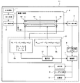
図1は、本実施の形態に係る質量分析装置の全体構成を概略的に示す図である。
図1において、質量分析装置11は、前処理部1、イオン化部2、イオン輸送部3、質量分析部4、イオン検出部5、データ処理部(CPU)6、制御部7、電圧制御部8、ユーザ入力部9、表示部10、及び記憶部13から概略構成されている。
前処理部1は、質量分析の対象となる試料に対して前処理を実施し、時間的に分離・分画するものであり、例えば、ガスクロマトグラフィー(GC:Gas Chromatography)や液体クロマトグラフィー(LC:Liquid Chromatography)が用いられる。イオン化部2では、前処理部1で前処理を施された試料が順次イオン化され、イオン化された試料(試料イオン)はイオン輸送部3によって搬送され、質量分析部4に入射される。
質量分析部4は、多重極電極系に直流電圧や高周波電圧を印加することにより生じる電界の作用によって試料イオンをイオン種毎に分離する原理のものであり、質量分析部4の上流側(入口側)から入射された試料イオン(試料イオンビーム)は、イオン種毎の質量電荷比(m/Z)に応じて分離され、特定の範囲の質量電荷比のイオン種が質量分析部4を通過して下流側(出口側)からイオン検出部5に射出される。ここで、質量電荷比のmはイオン質量を、Zはイオンの帯電荷数をそれぞれ示している。
イオン検出部5では、質量分析部4を通過したイオン種の試料イオンが検出され、検出結果がデータ処理部(CPU)6に送られて、例えば、質量電荷比(m/Z)毎の検出強度をあらわすデータとして処理され、制御部7に送られる。
制御部7は、質量分析装置11全体の動作を制御する。例えば、制御部7は、ユーザ入力部9への入力内容や、データ処理部6から送られてきたデータ等に基づいて電圧制御部8の動作を制御する。また、制御部7は、データ処理部6から送られてきたデータを表示部10に表示する。ユーザ入力部9等を介して入力される各種設定、データ処理部6からのデータ、各種プログラムや数式など、質量分析装置11の制御に関する情報は記憶部13に記憶される。
電圧制御部8は、制御部7からの指示に基づいて、質量分析部4を構成する複数の棒状電極(後述)に印加する直流電圧および高周波電圧を制御するものであり、制御部7からの指示に基づいて電圧を生成する電圧源12を有している。
ここで、質量分析部4の構成および試料イオンの分離について詳細に説明する。
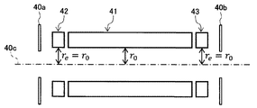
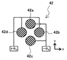
図2は、図1における質量分析部を拡大して模式的に示す図である。また、図3は図1の棒状電極の長手方向に対して垂直な面での位置Aにおける断面図、図4は位置Bにおける断面図、図5は位置Cにおける断面図である。図1~図5において、棒状電極で囲まれた空間の中心に棒状電極に沿って下流側方向にz軸、図1中上方向にy軸、図1中紙面手前方向にx軸を有する座標系を設定する。
本発明に係る質量分析部4は、仮想的な円筒上に互いに平行に配置された2n(nは2以上の整数)本の棒状電極から構成された多重極電極系と、多重極電極系の試料イオンが入射される側(上流側)の端部に多重極電極系を構成する棒状電極のそれぞれに対応するよう配置された複数の棒状電極から構成された補助電極系と、多重極電極系の試料イオンが射出される側(下流側)の端部に多重極電極系を構成する棒状電極のそれぞれに対応するよう配置された複数の棒状電極から構成された補助電極系とから構成されている。
本実施の形態においては、多重極電極系の一例として4本の棒状電極から構成された多重極電極系を例示して説明する。このように4つの棒状電極で構成された多重極電極系を用いる装置は、特に、四重極型質量分析計(QMS:quadrupole mass spectrometer)と称される。
すなわち、本実施の形態における質量分析部4は、仮想的な円筒上に互いに平行に配置された4本の棒状電極41a~41dから構成された四重極電極系41と、四重極電極系41の試料イオンが入射される側(上流側)の端部に四重極電極系41を構成する棒状電極41a~41dのそれぞれに対応するよう配置された複数の棒状電極42a~42dから構成された第1の補助電極系42と、四重極電極系41の試料イオンが射出される側(下流側)の端部に四重極電極系41を構成する棒状電極41a~41dのそれぞれに対応するよう配置された複数の棒状電極43a~43dから構成された第2の補助電極系43とから構成されている。なお、第1の補助電極系42の上流側には入口電極40aが、第2の補助電極系43の下流側には出口電極40bがそれぞれ設けられている。
四重極電極系41の棒状電極41a~41dは同じ長さに形成されており、その長手方向がz軸に沿うように、かつz軸方向の位置が同じになるよう配置されている。同様に、第1の補助電極系42の棒状電極42a~42dは同じ長さに形成されており、その長手方向がz軸に沿うように、かつz軸方向の位置が同じになるよう配置されている。また、第2の補助電極系43の棒状電極43a~43dは同じ長さに形成されており、その長手方向がz軸に沿うように、かつz軸方向の位置が同じになるよう配置されている。
なお、本実施の形態では、円柱形状の棒状電極を用いて四重極電極系41や第1及び第2の補助電極系42,43を構成しているが、例えば、棒状電極により囲まれる空間側(試料イオンが通過する側)において棒状電極の表面に沿うような双曲面形状を有する電極を棒状電極に代えて用いることもできる。
四重極電極系41を構成する棒状電極41a~41dにおいては、棒状電極41a~41dで囲まれる空間を挟んで対向する位置に配置された棒状電極を組とした場合、すなわち、棒状電極41a,41c及び棒状電極41b,41dをそれぞれ組とした場合、棒状電極41a,41cには下記(式1)で表されるような直流電圧と高周波電圧を重畳した電圧Φmainを印加し、棒状電極41b,41dには下記(式2)で表されるような直流電圧と高周波電圧を重畳した電圧(-Φmain)を印加する。棒状電極41a,41cに印加される電圧(式1)と、棒状電極41b,41dに印加される電圧(式2)とは、互いに逆位相となっている。


上記(式1)及び(式2)において、Uは直流電圧、VRFは高周波電圧の振幅、ΩRF(=2πfRF)は高周波電圧の角振動周波数をそれぞれ示している。
上記(式1)及び(式2)のように電圧印加された場合、四重極電極系41の棒状電極41a~41d間には、以下の(式3)及び(式4)で表される高周波電界Ex,Ey(四重極電界)が形成される。


上記(式3)及び(式4)において、r0は対向する1組の棒状電極間の距離の半値、すなわち、四重極電極系41の棒状電極41a~41dの仮想内接円筒の半径である。図2においては、棒状電極41a~41dの仮想内接円筒を線40cで示している。
イオン輸送部3によって搬送された試料イオンは、z軸に沿って四重極電極系41の中心に入射され、上記(式3)及び(式4)によって形成される電界Ex,Ey中を通過することになる。
このとき、試料イオンの飛行起動のx軸方向及びy軸方向の安定性は、棒状電極間でのイオン(試料イオン)の運動状態を表す運動方程式(Mathieu方程式)から導かれ無次元パラメータa,q(下記(式5)及び(式6)参照)によって求められる。
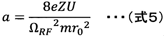

上記(式5)及び(式6)に示した無次元パラメータ(a,q)は、四重極型質量分析計(QMS)における安定性パラメータであり、r0は対向する1組の棒状電極間の距離の半値、eは素電荷、m/Zはイオンの質量電荷比、Uは棒状電極41a~41dに印加する直流電圧、VRFは棒状電極41a~41dに印加する高周波電圧の振幅、ΩRFは棒状電極41a~41dに印加する高周波電圧の角振動周波数である。
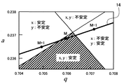
図6は、x軸方向及びy軸方向における試薬イオンの飛行軌道の安定性をa-q平面上に示した図である。また、図7は、図6における要部を拡大して示す図である。
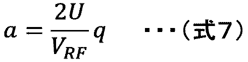
四重極電極系41に入射された試料イオンにおける安定性パラメータ(a,q)は、イオン種(質量電荷比m/Z)、半径r0、直流電圧U、振幅VRF、角振動周波数ΩRFなどの値に応じて図5で示されたa-q平面上の点をとる。また、上記(式5)及び(式6)において、半径r0、直流電圧U、振幅VRF、角振動周波数ΩRFの値が決まると、安定性パラメータ(a,q)は下記(式7)で表される直線(走査線14)上の何れかの点の値をとる。このとき、安定性パラメータ(a,q)は、各イオン種の質量電荷比m/Zに応じてそれぞれ走査線14上の異なる点をとる。
安定化パラメータ(a,q)が「x,y:安定」の領域(安定透過領域)の値をとる条件下では、その条件に該当するイオン種(試料イオン)は四重極電極系41を振動しながらz軸方向に安定して透過しイオン検出部5に到達する。また、安定化パラメータ(a,q)が「x,y:不安定」、「x:安定、y:不安定」、又は「x:不安定、y:安定」の領域の値をとる条件下では、その条件に該当するイオン種(試料イオン)は四重極電極系41でx-y平面方向の振動が発散するため安定して透過することができず、四重極電極系41の側方(x-y平面に沿う方向)に射出(不安定出射)される。
そこで、この特性を利用し、特定の質量電荷比m/Zを有するイオン種(試料イオン)をのみを通過させてイオン検出部5で検出するとともに、その他の質量電荷比m/Zを有するイオン種(試料イオン)を四重極電極系41の外に射出(不安定出射)させることにより、試料イオンにおける特定のイオン種を分離・検出することができる。
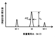
すなわち、図6の要部15の拡大図である図7に示すように、走査線14の傾き及び走査線14上において安定性パラメータ(a,q)が点Mで示されるイオン種のみが安定化領域の値をとり、かつ、他のイオン種(例えば、走査線14上において点Mと隣り合う点(M+1)及び点(M-1)の安定性パラメータ(a,q)をとるイオン種)が安定化領域外の値をとるように、上記(式5)及び(式6)を構成する各パラメータ(半径r0、直流電圧U、振幅VRF、角振動周波数ΩRF)を調整することにより、試料イオンにおける特定のイオン種を分離・検出することができ、図8に示すような質量スペクトルデータを得ることができる。図8では、横軸に質量電荷比m/Z、縦軸にイオンの検出数(検出強度)を示している。
第1の補助電極系42においても四重極電極系41と同様に、棒状電極42a~42dで囲まれる空間を挟んで対向する位置に配置された棒状電極を組とした場合、すなわち、棒状電極42a,42c及び棒状電極42b,42dをそれぞれ組とした場合、棒状電極42a,42cには下記(式8)で表されるような直流電圧と高周波電圧を重畳した電圧Φeを印加し、棒状電極42b,42dには下記(式9)で表されるような直流電圧と高周波電圧を重畳した電圧(-Φe)を印加する。棒状電極42a,42cに印加される電圧(式8)と、棒状電極42b,42dに印加される電圧(式9)とは、互いに逆位相となっている。


上記(式8)及び(式9)において、Ueは直流電圧、Veは高周波電圧の振幅、Ωeは高周波電圧の角振動周波数をそれぞれ示している。
第2の補助電極系43においても第1の補助電極系42及び四重極電極系41と同様に、棒状電極43a~43dで囲まれる空間を挟んで対向する位置に配置された棒状電極を組とした場合、すなわち、棒状電極43a,43c及び棒状電極43b,43dをそれぞれ組とした場合、棒状電極43a,43cには(式8)で表されるような直流電圧と高周波電圧を重畳した電圧Φeを印加し、棒状電極43b,43dには(式9)で表されるような直流電圧と高周波電圧を重畳した電圧(-Φe)を印加する。
以上のように構成した本実施の形態の四重極電極系41では、前述のように、多重極電極系の内部に形成された電界の内部を試料イオンが通過する際のイオン種毎(つまり質量電荷比m/Z毎)の固有振動数が異なり、安定振幅で振動して多重極電極系の下流側端部まで飛行する質量電荷比m/Zのイオン種と振幅が増幅して多重極電極系の外部に射出される質量電荷比m/Zのイオン種とがあるとう原理を利用して質量分離を行う。
ここで、本願発明の創出に際し発明者らは、四重極電極系41の内部を通過する際の試料イオンの振動回数が分解能に影響する可能性に着目し、四重極電極系41を通過する際の振動回数が少ないと、イオン種毎の質量電荷比m/Zの観点から隣接するイオン種間での振動周波数(固有振動数)の相違が質量分離に十分に作用せず、目的とするイオン種と隣接するイオン種との分離が不十分となってマスピークが広がる、言い換えると分解能が低下すると考えた。
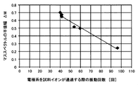
図9は、四重極電極系を通過する試料イオンの振動回数と分解能の関係を示すシミュレーション結果である。図9では、縦軸にマススペクトルの半値幅(ΔM)を、横軸に四重極電極系を試料イオンが通過する際の振動回数(回)をそれぞれ示している。
図9において、縦軸に示したマススペクトルの半値幅は分解能(M/ΔM)に直接関係する指標として見ることができる。すなわち、図9からは、四重極電極系41内を通過する際の試料イオンの振動回数が分解能に大きく影響し、振動回数が増加するほど分解能(M/ΔM)が高くなることがわかる。
図10は、四重極電極系単体における電位ポテンシャルのシミュレーション結果を示す図である。
図10に示すように、四重極電極系41の内部では棒状電極41a~41dに印加される電圧(直流電圧、高周波電圧)に応じて電位ポテンシャルが形成されている。図10からは、四重極電極系41の中央部分では一定の電位ポテンシャルが形成されており、四重極電極系41の両端部では端部に向かって出にポテンシャルが減少していることがわかる。そして、このように形成された電位ポテンシャルがある一定以上である場合に四重極電極系41内を通過する試料イオンの運動状態に実効的な影響を及ぼすと考えることができる。
そこで、分解能(M/ΔM)がΔM/M=2(Δr/r0)から導出されることを考え、分析に必要な分解能(M/ΔM)を満足する誤差(Δr/r0)となる範囲を実効長Lpとして定義する。図11は、電位ポテンシャルの実行長についての説明図である。誤差(Δr/r0)は、四重極電極系の組立誤差を表す場合もあるが、本実施の形態では、実際の四重極電極系の組立誤差ではなく、四重極電極系(組立誤差も含む)の内部に形成される電界の誤差(歪み)を四重極電極系の組立誤差に換算したものとする。つまり、四重極電極系の端部では電界の歪み(端部歪みLd)が大きいので、実際の組立誤差よりも誤差(Δr/r0)は大きくなる。
なお、実効長の定義については上記に限定されるものではなく、他の根拠から四重極電極系41を通過する試料イオンの運動状態に実効的に作用すると想定される範囲を算出して実効長と定めても良い。すなわち、四重極電極系41内部において電界(四重極電界)が形成される領域のz軸方向の長さとして、特に、試料イオンの分離に実効的に作用する(すなわち分解能に寄与する)と考えられる高精度な電界の長さを指して実効長と定めれば良い。
四重極電極系を含む多重極電極系においては、電位ポテンシャルの実効長が長いほど、つまり、試料イオンに実効的に作用する距離が長いほど振動回数が増えるので、分解能が高くなるということが言える。言い換えれば、実効長の低下を抑制することができれば、分解能の低下も抑制することができると言える。
本願発明は、多重極電極系を用いる質量分析装置の分解能は試料イオンが通過する電位ポテンシャルの実効長に影響されるという発明者の新たな知見に基づくものである。四重極電極系41と補助電極系42,43の電極系の物理的な長さを延長することなく実効長を延長するためには、下記(式10)を満たすように質量分析部4及び電圧制御部8(制御部7)を構成し、補助電極系42,43を含む四重極電極系41の端部の電位ポテンシャルの減少を抑制する必要がある。

すなわち、補助電極系42,43の仮想内接円筒の半径reに対する補助電極系42,43に印加される高周波電圧の振幅Veの大きさの比よりも四重極電極系41の仮想内接円筒の半径r0に対する四重極電極系41に印加される高周波電圧の振幅VRFの大きさの比が大きくなるように構成する必要がある。
本実施の形態では下記(式11)~(式14)を満たすように質量分析部4及び電圧制御部8(制御部7)を構成・制御することにより上記(式10)を満たすように質量分析装置11を構成している。




上記(式11)に示すように、四重極電極系41の仮想内接円筒の半径r0と補助電極系42,43の仮想内接円筒の半径reとが同じとなるように質量分析部4を構成し、(式12)~(式14)を満たすように四重極電極系41及び補助電極系42,43に電圧(直流電圧と高周波電圧)を印加する。
図12は、本実施の形態における質量分析部における電位ポテンシャルのシミュレーション結果を示す図である。
図12に示したシミュレーション結果では、図10に示した四重極電極系単体におけるシミュレーション結果と比較して、補助電極系42,43を含む四重極電極系41の端部の電位ポテンシャルの減少が抑制されており、実効長Lpが延長されていることがわかる。
以上のように構成した本実施の形態の効果を説明する。
質量分析装置においては様々な使用環境に対応するための方策の一つとして小型化が望まれている。質量分析装置の小型化には装置の一定の割合を占める電極の小型化も必要となるが、単に電極棒(棒状電極)を短くした場合にはイオンの分離において対象のイオンに作用する電界の長さも短くなってしまうため、質量分析装置における分解能が低下してしまうという課題があった。
これに対して本実施の形態においては、仮想円筒上に互いに平行に配置された4本の棒状電極41a~41dから構成された四重極電極系41と、四重極電極系41の少なくとも一端に配置され、四重極電極系41を構成する複数の棒状電極41a~41dのそれぞれに対応するよう配置された複数の棒状電極42a~42d,43a~43dから構成された補助電極系42,43と、四重極電極系41および補助電極系42,43にそれぞれ直流電圧および高周波電圧を印加する電圧制御部8とを備え、補助電極系42,43の仮想内接円筒の半径reに対する補助電極系42,43に印加される高周波電圧の振幅Veの大きさの比よりも四重極電極系41の仮想内接円筒の半径r0に対する四重極電極系41に印加される高周波電圧の振幅VRFの大きさの比が大きくなるように構成したので、補助電極系42,43を含む四重極電極系41の端部の電位ポテンシャルの減少を抑制することができ、四重極電極系41と補助電極系42,43の電極系の物理的な長さを延長することなく実効長を延長することができる。すなわち、質量分析装置の小型化に際して棒状電極の小型化(短縮)を行う場合にも、電位ポテンシャルの実効長を延長することができるので、分解能の低下を抑制しつつ質量分析装置の小型化を図ることができる。
また、質量分析装置の小型化を行わない場合にも、電位ポテンシャルの実効長を延長することができるので、電極系の物理的な長さを延長することなく分解能の向上を図ることができる。
<第1の実施の形態の変形例>
第1の実施の形態の変形例について説明する。
第1の実施の形態の変形例について説明する。
本変形例は、第1の実施の形態における第1及び第2の補助電極系42,43の電位を第1の補助電極系42と第2の補助電極系43とで異ならせるものである。
具体的には、第1の実施の形態において第1及び第2の補助電極系42,43について示した(式8)~(式14)の各変数の下付文字eをe1と読み替えて本変形例の第1の補助電極系42に適用するとともに、(式8)~(式14)の各変数の下付文字eをe2と読み替えて本変形例の第2の補助電極系43に適用する。ただし、|Ve1|≠|Ve2|、|Ue1|≠|Ue2|である。
その他の構成は第1の実施の形態と同様である。
以上のように構成した本変形例においても第1の実施の形態と同様の効果を得ることができる。
また、四重極電極系41の前後(上流側端部と下流側端部)で組み立て誤差が異なる場合であっても微調整することができ、より高精度に端部の電界歪みを抑制することができる。
<第2の実施の形態>
本発明の第2の実施の形態を図13及び図14を参照しつつ説明する。
本発明の第2の実施の形態を図13及び図14を参照しつつ説明する。
本実施の形態は、第1の実施の形態において(式10)を達成するために(式11)に代えて(式15)を用いる場合のものである。
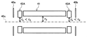
図13は、本実施の形態における質量分析部を拡大して模式的に示す図である。図中、第1の実施の形態と同様の部材には同じ符号を付し説明を省略する。
本実施の形態では下記(式15)~(式18)を満たすように質量分析部4及び電圧制御部8(制御部7)を構成・制御することにより上記(式10)を満たすように質量分析装置11を構成している。




上記(式15)に示すように、四重極電極系41の仮想内接円筒の半径r0よりも補助電極系42A,43Aの仮想内接円筒の半径reが小さくなるように質量分析部4を構成し、(式16)~(式18)を満たすように四重極電極系41及び補助電極系42A,43Aに電圧(直流電圧と高周波電圧)を印加する。
特に、上記(式17)において|Ue|=|U|とする場合には、図14に示すように、四重極電極系41と第1及び第2の補助電極系42A,43Aとを一体的に構成して四重極電極系41Aとすることができる。このとき、補助電極系部421A,431Aが補助電極系42A,43Aとして機能する。
その他の構成は第1の実施の形態と同様である。
以上のように構成した本実施の形態においても第1の実施の形態と同様の効果を得ることができる。
また、四重極電極系41と第1及び第2の補助電極系42A,43Aとを一体的に構成して四重極電極系41Aとした場合には、電極系に印加する電圧の種類を削減することができるため、電源数も削減することができ、電圧の制御がより容易になるとともに、コスト低減を行うことができる。
さらに、電極系を一体構成することによって電極系の製造精度を向上することができる。
<第1及び第2の実施の形態の変形例>
本発明の第1及び第2の実施の形態の変形例を図15~図17を参照しつつ説明する。
本発明の第1及び第2の実施の形態の変形例を図15~図17を参照しつつ説明する。
本変形例は、第1及び第2の実施の形態において、四重極電極系の射出側(下流側)にのみ補助電極系を用いる場合を示すものである。
図15~図17は、本変形例における質量分析部を拡大して模式的に示す図であり、それぞれ、図15は第1及実施の形態に、図16及び図17は第2の実施の形態に対応する。図中、第1及び第2の実施の形態と同様の部材には同じ符号を付し説明を省略する。
図15に示すように、本変形例では、第2の補助電極系43のみを設置し、(式11)~(式14)を満たすように質量分析部4及び電圧制御部8(制御部7)を構成・制御することにより(式10)を満たすように質量分析装置11を構成している。つまり、(式11)に示すように、四重極電極系41Bの仮想内接円筒の半径r0と補助電極系43の仮想内接円筒の半径reとが同じとなるように質量分析部4を構成し、(式12)~(式14)を満たすように四重極電極系41及び補助電極系43に電圧(直流電圧と高周波電圧)を印加する。その他の構成は第1の実施の形態と同様である。
また、図16に示すように、本変形例では、第2の補助電極系43のみを設置し、(式15)~(式18)を満たすように質量分析部4及び電圧制御部8(制御部7)を構成・制御することにより(式10)を満たすように質量分析装置11を構成している。つまり、(式15)に示すように、四重極電極系41Bの仮想内接円筒の半径r0よりも補助電極系43Aの仮想内接円筒の半径reが小さくなるように質量分析部4を構成し、(式16)~(式18)を満たすように四重極電極系41B及び補助電極系43Aに電圧(直流電圧と高周波電圧)を印加する。特に、(式17)において|Ue|=|U|とする場合には、図17に示すように、四重極電極系41と第1及び第2の補助電極系43Aとを一体的に構成して四重極電極系41Cとすることができる。このとき、補助電極系部431Aが補助電極系43Aとして機能する。その他の構成は第2の実施の形態と同様である。
以上のように構成した本実施の形態においても第1及び第2の実施の形態と同様の効果を得ることができる。
また、質量分析部4における試料イオンの入射側(上流側)端部に補助電極系(すなわち補助電界)が印加されていないため、イオン入射率への影響がなく、高い入射率を確保することができる。また、質量分析部4の射出側(下流側)端部には補助電極系43Aを設置しているため、電位ポテンシャルの実効長のを延長することができる。
なお、本変形例では、第1及び第2の実施の形態において、四重極電極系の射出側(下流側)にのみ補助電極系を用いる場合を説明したが、四重極電極系の射出側(上流側)にのみ補助電極系を用いる場合についても同様に考えることができる。
すなわち、第2の補助電極系42のみを設置し、(式11)~(式14)を満たすように質量分析部4及び電圧制御部8(制御部7)を構成・制御することにより(式10)を満たすように質量分析装置11を構成しても良い。つまり、(式11)に示すように、四重極電極系41の仮想内接円筒の半径r0と補助電極系42の仮想内接円筒の半径reとが同じとなるように質量分析部4を構成し、(式12)~(式14)を満たすように四重極電極系41及び補助電極系42に電圧(直流電圧と高周波電圧)を印加するように構成しても良い。
また、第2の補助電極系42のみを設置し、(式15)~(式18)を満たすように質量分析部4及び電圧制御部8(制御部7)を構成・制御することにより(式10)を満たすように質量分析装置11を構成しても良い。つまり、(式15)に示すように、四重極電極系41の仮想内接円筒の半径r0よりも補助電極系43Aの仮想内接円筒の半径reが小さくなるように質量分析部4を構成し、(式16)~(式18)を満たすように四重極電極系41及び補助電極系43Aに電圧(直流電圧と高周波電圧)を印加するように構成しても良い。特に、(式17)において|Ue|=|U|とする場合には、四重極電極系41と第1及び第2の補助電極系43Aとを一体的に構成した四重極電極系とすることができる。
<第3の実施の形態>
本発明の第3の実施の形態を図18及び図19を参照しつつ説明する。
本発明の第3の実施の形態を図18及び図19を参照しつつ説明する。
本実施の形態は、第1及び第2の実施の形態において、四重極電極系への入射エネルギーや電極系に印加する高周波電圧の角振動周波数を調整する機能(印加電圧調整処理機能)を持たせたものである。
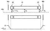
図18は、本実施の形態における質量分析部を拡大するとともに、電極系に印加するオフセット電圧(-Voff)を模式的に示す図である。また、図19は、印加電圧調整処理を示すフローチャートである。図中、第1及び第2の実施の形態と同様の部材には同じ符号を付し説明を省略する。
図19において、制御部7(電圧制御部8)は、まず、ユーザの入力に基づいて、ターゲットイオン種の質量電荷比(m/Z)を設定する(ステップS10)。続いて、ΔM=0.5として必要な目標分解能(M/ΔM)を算出する(ステップS20)。続いて補助電極系に印加する電圧Ue,Veを算出し(ステップS30)、算出結果に基づいて補助電極系に電圧(直流電圧と高周波電圧)を印加する(ステップS40)。続いて、入射エネルギー(オフセット電圧Voff:図18参照)を調整し(ステップS50)、四重極電極系に印加する電圧の角振動周波数(ΩRF)を調整する(ステップS60)。続いて、基準分解能(実測データ、あるいは、定式から算出される分解能)と分解能とを比較し(ステップS70)、分解能の比較結果から目標値を満たしているかどうか(分可能(M/ΔM)は規定の目標値以下であるかどうか、あるいは、目標値の±20%以内で一致しているかどうか)を判定する(ステップS80)。ステップS80での判定結果がNOの場合には、判定結果がYESになるまでステップS30~S70の処理を繰り返し、ステップS80での判定結果がYESの場合には、処理を終了する。
その他の構成は第1及び第2の実施の形態と同様である。
以上のように構成した本実施の形態においても第1及び第2の実施の形態と同様の効果を得ることができる。
また、ターゲットイオン種の質量電荷比(m/Z)に応じた条件最適化を実施することができるので、高分解能分析の確度を向上することができる。
<その他の変形例>
なお、補助電極系42,43のz軸方向の長さをle、四重極電極系41と補助電極系42,43とを合わせた全体長をl0とした場合、補助電極系42,43の長さ(2×le)が占める割合が全体長l0の20%以下となるように構成する。例えば、図20に示すように、第1の実施の形態(図2等参照)における補助電極系42,43の長さ(2×le)が占める割合が全体長l0の20%以下となるように構成する。または、図21に示すように、第2の実施の形態(図14等参照)における補助電極系部421A,431Aの長さ(2×le)が占める割合が全体長l0の20%以下となるように構成する。以上のように構成することにより、より効果的に端部の電位ポテンシャルの減少を軽減することができる。
なお、補助電極系42,43のz軸方向の長さをle、四重極電極系41と補助電極系42,43とを合わせた全体長をl0とした場合、補助電極系42,43の長さ(2×le)が占める割合が全体長l0の20%以下となるように構成する。例えば、図20に示すように、第1の実施の形態(図2等参照)における補助電極系42,43の長さ(2×le)が占める割合が全体長l0の20%以下となるように構成する。または、図21に示すように、第2の実施の形態(図14等参照)における補助電極系部421A,431Aの長さ(2×le)が占める割合が全体長l0の20%以下となるように構成する。以上のように構成することにより、より効果的に端部の電位ポテンシャルの減少を軽減することができる。
また、四重極電極系と補助電極系が分離している場合(すなわち別体として形成している場合)においては、下記(式19)を満足するように補助電極系に印加する電圧を制御することにより、より効果的に端部の電位ポテンシャルの減少を軽減することができる。

なお、本発明は上記した実施例に限定されるものではなく、様々な変形例が含まれる。例えば、上記した実施例は本発明を分かりやすく説明するために詳細に説明したものであり、必ずしも説明した全ての構成を備えるものに限定されるものではない。また、上記の各構成、機能等は、それらの一部又は全部を、例えば集積回路で設計する等により実現してもよい。また、上記の各構成、機能等は、プロセッサがそれぞれの機能を実現するプログラムを解釈し、実行することによりソフトウェアで実現してもよい。
1 前処理部
2 イオン化部
3 イオン輸送部
4 質量分析部
5 イオン検出部
6 データ処理部(CPU)
7 制御部
8 電圧制御部
9 ユーザ入力部
10 表示部
11 質量分析装置
12 電圧源
13 記憶部
14 走査線
15 要部
40a 入口電極
40b 出口電極
41,41A,41B,41C 四重極電極系
41a~41d,42a~42d,43a~43d 棒状電極
42,42A,43,43A 補助電極系
421A,431A 補助電極系部
2 イオン化部
3 イオン輸送部
4 質量分析部
5 イオン検出部
6 データ処理部(CPU)
7 制御部
8 電圧制御部
9 ユーザ入力部
10 表示部
11 質量分析装置
12 電圧源
13 記憶部
14 走査線
15 要部
40a 入口電極
40b 出口電極
41,41A,41B,41C 四重極電極系
41a~41d,42a~42d,43a~43d 棒状電極
42,42A,43,43A 補助電極系
421A,431A 補助電極系部
Claims (12)
- 仮想円筒上に互いに平行に配置された2n(nは2以上の整数)本の棒状電極から構成された多重極電極系と、
前記多重極電極系の少なくとも一端に配置され、前記多重極電極系を構成する複数の棒状電極のそれぞれに対応するよう配置された複数の棒状電極から構成された補助電極系と、
前記多重極電極系および補助電極系にそれぞれ直流電圧および高周波電圧を印加する電圧制御部とを備え、
前記補助電極系の仮想内接円筒の半径に対する前記補助電極系に印加される高周波電圧の振幅の大きさの比よりも前記多重極電極系の仮想内接円筒の半径に対する前記多重極電極系に印加される高周波電圧の振幅の大きさの比が大きくなるように構成されたことを特徴とする質量分析装置。 - 請求項1記載の質量分析装置において、
前記補助電極系は、その内接円筒の半径が前記多重極電極系の内接円筒の半径以下になるように形成され、
前記電圧制御部は、前記補助電極系に印加される高周波電圧の振幅の大きさが前記多重極電極系に印加される高周波電圧の振幅の大きさよりも大きくなるように制御することを特徴とする質量分析装置。 - 請求項1記載の質量分析装置において、
前記補助電極系は、その内接円筒の半径が前記多重極電極系の内接円筒の半径よりも小さくなるように形成され、
前記電圧制御部は、前記補助電極系に印加される高周波電圧の振幅の大きさと前記多重極電極系に印加される高周波電圧の振幅の大きさが同じになるように制御することを特徴とする質量分析装置。 - 請求項3記載の質量分析装置において、
前記補助電極系と前記多重極電極系が動電位となるよう一体的に形成されたことを特徴とする質量分析装置。 - 請求項1記載の質量分析装置において、
前記補助電極系は、前記多重極電極系において質量分析の対象となるイオン化された試料が入射される側の端部に配置されたことを特徴とする質量分析装置。 - 請求項1記載の質量分析装置において、
前記補助電極系は、前記多重極電極系において質量分析の対象となるイオン化された試料が入射される側と反対側の端部に配置されたことを特徴とする質量分析装置。 - 請求項1記載の質量分析装置において、
前記補助電極系は、前記多重極電極系の両端に配置されたことを特徴とする質量分析装置。 - 請求項1記載の質量分析装置において、
前記電圧制御部は、前記多重極電極系に印加される高周波電圧の角振動周波数を増加させるように制御することを特徴とする質量分析装置。 - 請求項8記載の質量分析装置において、
前記電圧制御部は、さらに、質量分析の対象となるイオン化された試料の前記多重極電極系への入射エネルギーを低下させるように制御することを特徴とする質量分析装置。 - 請求項1記載の質量分析装置において、
前記補助電極系の長さは、前記多重極電極系と前記補助電極系とからなる電極全体の20%以下であることを特徴とする質量分析装置。 - 請求項1記載の質量分析装置において、
前記補助電極系の仮想内接円筒の半径に対する前記補助電極系に印加される高周波電圧の振幅の大きさの比と前記多重極電極系の仮想内接円筒の半径に対する前記多重極電極系に印加される高周波電圧の振幅の大きさの比の差が、前記補助電極系の仮想内接円筒の半径に対する前記補助電極系に印加される高周波電圧の振幅の大きさの比の20%以下であることを特徴とする質量分析装置。 - 請求項1記載の質量分析装置において、
前記補助電極系に印加される直流電圧の大きさは、前記多重極電極系に印加される直流電圧の大きさ以下であることを特徴とする質量分析装置。
Applications Claiming Priority (2)
| Application Number | Priority Date | Filing Date | Title |
|---|---|---|---|
| JP2016-143203 | 2016-07-21 | ||
| JP2016143203A JP6735620B2 (ja) | 2016-07-21 | 2016-07-21 | 質量分析装置 |
Publications (1)
| Publication Number | Publication Date |
|---|---|
| WO2018016408A1 true WO2018016408A1 (ja) | 2018-01-25 |
Family
ID=60993020
Family Applications (1)
| Application Number | Title | Priority Date | Filing Date |
|---|---|---|---|
| PCT/JP2017/025505 Ceased WO2018016408A1 (ja) | 2016-07-21 | 2017-07-13 | 質量分析装置 |
Country Status (2)
| Country | Link |
|---|---|
| JP (1) | JP6735620B2 (ja) |
| WO (1) | WO2018016408A1 (ja) |
Citations (6)
| Publication number | Priority date | Publication date | Assignee | Title |
|---|---|---|---|---|
| JP2000077025A (ja) * | 1998-08-31 | 2000-03-14 | Shimadzu Corp | 四重極質量分析装置 |
| JP2001307674A (ja) * | 2000-04-21 | 2001-11-02 | Yokogawa Analytical Systems Inc | 誘導結合プラズマ質量分析装置 |
| JP2015503827A (ja) * | 2011-12-29 | 2015-02-02 | ディーエイチ テクノロジーズ デベロップメント プライベート リミテッド | イオントラップ質量分析のためのイオン励起方法 |
| JP2015507820A (ja) * | 2011-12-21 | 2015-03-12 | サーモ フィッシャー サイエンティフィック (ブレーメン) ゲーエムベーハー | 衝突セル多重極 |
| WO2015198721A1 (ja) * | 2014-06-25 | 2015-12-30 | 株式会社 日立ハイテクノロジーズ | 質量分析装置 |
| WO2017081770A1 (ja) * | 2015-11-11 | 2017-05-18 | 株式会社島津製作所 | 四重極マスフィルタ及び四重極型質量分析装置 |
-
2016
- 2016-07-21 JP JP2016143203A patent/JP6735620B2/ja active Active
-
2017
- 2017-07-13 WO PCT/JP2017/025505 patent/WO2018016408A1/ja not_active Ceased
Patent Citations (6)
| Publication number | Priority date | Publication date | Assignee | Title |
|---|---|---|---|---|
| JP2000077025A (ja) * | 1998-08-31 | 2000-03-14 | Shimadzu Corp | 四重極質量分析装置 |
| JP2001307674A (ja) * | 2000-04-21 | 2001-11-02 | Yokogawa Analytical Systems Inc | 誘導結合プラズマ質量分析装置 |
| JP2015507820A (ja) * | 2011-12-21 | 2015-03-12 | サーモ フィッシャー サイエンティフィック (ブレーメン) ゲーエムベーハー | 衝突セル多重極 |
| JP2015503827A (ja) * | 2011-12-29 | 2015-02-02 | ディーエイチ テクノロジーズ デベロップメント プライベート リミテッド | イオントラップ質量分析のためのイオン励起方法 |
| WO2015198721A1 (ja) * | 2014-06-25 | 2015-12-30 | 株式会社 日立ハイテクノロジーズ | 質量分析装置 |
| WO2017081770A1 (ja) * | 2015-11-11 | 2017-05-18 | 株式会社島津製作所 | 四重極マスフィルタ及び四重極型質量分析装置 |
Also Published As
| Publication number | Publication date |
|---|---|
| JP2018014242A (ja) | 2018-01-25 |
| JP6735620B2 (ja) | 2020-08-05 |
Similar Documents
| Publication | Publication Date | Title |
|---|---|---|
| JP4735775B2 (ja) | 四重極型質量分析装置 | |
| US8664590B2 (en) | Method of processing image charge/current signals | |
| JP4665970B2 (ja) | 四重極型質量分析装置 | |
| JP4941437B2 (ja) | 四重極型質量分析装置 | |
| CN107799383B (zh) | 静电阱质量分析器的操作方法 | |
| WO2009144765A1 (ja) | 四重極型質量分析装置 | |
| US10607825B2 (en) | Mass spectrometer | |
| JP6022383B2 (ja) | 質量分析システム、及び方法 | |
| US11276544B2 (en) | Dynamic electron impact ion source | |
| JP6277272B2 (ja) | 質量分析装置 | |
| CN115513039B (zh) | 将离子注入静电阱的设备和方法 | |
| JP6593451B2 (ja) | 四重極マスフィルタ及び四重極型質量分析装置 | |
| JP6735620B2 (ja) | 質量分析装置 | |
| US20190035618A1 (en) | Quadrupole mass filter and quadrupole type mass spectrometry device | |
| US20240290605A1 (en) | Mass spectrometer and method | |
| JP6711407B2 (ja) | イオンガイド及び質量分析装置 | |
| JP2015118887A (ja) | 飛行時間型質量分析装置 | |
| CN112103169B (zh) | 一种针对离子阱的调整方法和离子阱 | |
| JP6954465B2 (ja) | 四重極マスフィルタおよび分析装置 | |
| RU2398308C1 (ru) | Способ масс-разделения ионов по времени пролета и устройство для его осуществления | |
| US20230014104A1 (en) | Devices and methods for generating resonance excitation for an ion manipulation apparatus | |
| WO2023037536A1 (ja) | 質量分析装置 | |
| WO2016114151A1 (ja) | 質量分析装置 |
Legal Events
| Date | Code | Title | Description |
|---|---|---|---|
| 121 | Ep: the epo has been informed by wipo that ep was designated in this application |
Ref document number: 17830927 Country of ref document: EP Kind code of ref document: A1 |
|
| NENP | Non-entry into the national phase |
Ref country code: DE |
|
| 122 | Ep: pct application non-entry in european phase |
Ref document number: 17830927 Country of ref document: EP Kind code of ref document: A1 |