WO2018016253A1 - サンルーフ装置 - Google Patents
サンルーフ装置 Download PDFInfo
- Publication number
- WO2018016253A1 WO2018016253A1 PCT/JP2017/022545 JP2017022545W WO2018016253A1 WO 2018016253 A1 WO2018016253 A1 WO 2018016253A1 JP 2017022545 W JP2017022545 W JP 2017022545W WO 2018016253 A1 WO2018016253 A1 WO 2018016253A1
- Authority
- WO
- WIPO (PCT)
- Prior art keywords
- sliding member
- vehicle
- rotation
- movable panel
- engagement
- Prior art date
- Legal status (The legal status is an assumption and is not a legal conclusion. Google has not performed a legal analysis and makes no representation as to the accuracy of the status listed.)
- Ceased
Links
Images





Classifications
-
- B—PERFORMING OPERATIONS; TRANSPORTING
- B60—VEHICLES IN GENERAL
- B60J—WINDOWS, WINDSCREENS, NON-FIXED ROOFS, DOORS, OR SIMILAR DEVICES FOR VEHICLES; REMOVABLE EXTERNAL PROTECTIVE COVERINGS SPECIALLY ADAPTED FOR VEHICLES
- B60J7/00—Non-fixed roofs; Roofs with movable panels, e.g. rotary sunroofs
- B60J7/02—Non-fixed roofs; Roofs with movable panels, e.g. rotary sunroofs of sliding type, e.g. comprising guide shoes
- B60J7/04—Non-fixed roofs; Roofs with movable panels, e.g. rotary sunroofs of sliding type, e.g. comprising guide shoes with rigid plate-like element or elements, e.g. open roofs with harmonica-type folding rigid panels
- B60J7/05—Non-fixed roofs; Roofs with movable panels, e.g. rotary sunroofs of sliding type, e.g. comprising guide shoes with rigid plate-like element or elements, e.g. open roofs with harmonica-type folding rigid panels pivoting upwardly to vent mode and moving downward before sliding to fully open mode
Definitions
- the present invention relates to a sunroof device.
- a sunroof device for example, a so-called outer slide sunroof device described in Patent Document 1 is known.
- This sunroof device is provided so as to be movable along each guide rail, a movable panel that opens and closes an opening formed in the roof of the vehicle, guide rails provided at both edges of the opening in the vehicle width direction, and A first sliding member (drive shoe) linked to each of both edge portions of the movable panel in the vehicle width direction, and an electric drive source for moving both first sliding members are provided.
- the sunroof device is connected to each of both edge portions of the movable panel in the vehicle width direction in front of the first sliding member and is movable along the guide rail integrally with the movable panel.
- a sliding member (slide check) is provided. Further, the sunroof device has a guide block (check block) provided on each guide rail and having an engagement groove, and an engagement protrusion that can be engaged with the engagement groove, and is rotated around the second sliding member. And a rotation check connected movably.
- the movable panel shifts to a tilt-up state when the first sliding member moves forward of the vehicle with respect to the second sliding member in the fully closed state.
- the movable panel also includes the first sliding member so that the second sliding member moves integrally with the first sliding member when the first sliding member moves further forward of the vehicle and then rearward of the vehicle. When the sliding member and the second sliding member are engaged, the opening operation is performed in the tilted-up state.
- the engaging protrusion of the rotation check is engaged with the engaging groove of the guide block, and the second sliding member is moved when the first sliding member moves forward of the vehicle. Movement is restricted together with the movable panel.
- the engaging protrusion is rotated so as to be disengaged from the engaging groove, and the second sliding member and the movable panel are moved. The movement restriction is released.
- the movable panel closes in the tilted-up state.
- the movable panel then shifts (returns) to the fully closed state when the first sliding member moves rearward of the vehicle while releasing the engagement with the second sliding member.
- the first sliding member moves forward of the vehicle so that the movable panel can be closed while the movable panel is tilted up in the open state of the movable panel
- the first sliding member presses the engaging protrusion.
- the second sliding member moves forward with the first sliding member together with the first sliding member.
- the engaging protrusion releases the engagement with the first sliding member while engaging the engaging groove.
- the movement of the second sliding member and the movable panel is regulated by being rotated so as to be engaged with the second sliding member. Therefore, when the first sliding member moves to the rear of the vehicle so as to shift to the fully closed state, the engagement protrusion is in a state in which the engagement with the first sliding member is released.
- the rotation check has a structure in which the engagement protrusion is rotated in a mode guided by the engagement groove, and therefore, the rotation of the engagement protrusion cannot be stopped when a force is applied to the rear of the vehicle. .
- the first sliding member and the second sliding member that are in an engaged state move integrally to the rear of the vehicle, resulting in malfunction.
- An object of the present invention is to provide a sunroof device that can suppress the occurrence of malfunctions.
- a sunroof device that solves the above problems includes a movable panel configured to open and close an opening formed in a roof of a vehicle, guide rails provided at both edges of the opening in the vehicle width direction, and the movable panel.
- a first sliding member linked to both edges in the vehicle width direction and driven to move along the corresponding guide rail by an electric drive source;
- a second sliding member movable along the guide rail, a guide block provided on each of the guide rails, and a guide block having an engagement groove, and engaging with the engagement groove.
- a rotation check having engagement protrusions for restricting movement of the second sliding member, the rotation check being rotated around an axis extending in the vehicle longitudinal direction;
- the engaging protrusions are connected to the corresponding second sliding members so as to be freely movable, and the engaging protrusions are engaged with the first sliding members when the second sliding members move rearward of the vehicle.
- a rotation check that is rotated so as to be disengaged from the groove, and a rotation-preventing member that is movably connected in the front-rear direction to the corresponding second sliding member at the rear of the vehicle relative to the rotation check.
- the anti-rotation member configured to enter the rotation locus of the rotation check in a state where the engagement protrusion is engaged with the engagement groove with the movement of the anti-rotation member.
- the urging member that urges toward the front and the corresponding first sliding member in the fully closed state of the movable panel move toward the rear of the vehicle following the movement toward the front of the vehicle
- the urging member The detent portion corresponding to the urging force of The and a composed engaging and disengaging the switching mechanism so as to move the corresponding second sliding member integral with said first sliding member while moving to the rear of the vehicle.
- a sunroof device that solves the above problems includes a movable panel configured to open and close an opening formed in a roof of a vehicle, guide rails provided at both edges of the opening in the vehicle width direction, and the movable panel.
- a first sliding member linked to both edges in the vehicle width direction and driven to move along the corresponding guide rail by an electric drive source;
- a supporting pin having a second sliding member movable along the guide rail and a central axis extending in the vehicle front-rear direction and extending from the corresponding second sliding member toward the rear of the vehicle,
- a support pin having a retaining portion at the rear end and having a fitting portion in front of the vehicle with respect to the retaining portion, and a guide block provided on each of the guide rails.
- a rotation check having a guide block having an engagement groove, and an engagement protrusion that engages with the engagement groove and restricts the movement of the corresponding second sliding member,
- the rotation check is rotatably supported by the support pin so that the engagement protrusion is disengaged from the engagement groove when the second sliding member moves rearward together with the first sliding member.
- a rotation check that is pivoted to the support pin, a rotary cam that is adjacent to the retaining portion on the vehicle front side and is rotatably supported by the support pin, and the first sliding member that is concentric with the rotary cam And the second sliding member is moved when the first sliding member moves to the rear of the vehicle following the movement to the front of the vehicle in the fully closed state of the movable panel.
- the fixed cap is moved so as to move integrally with the first sliding member. Is fixedly engaged with the rotating cam while rotating the rotating cam by a pressing action with the rotating cam, and is disposed adjacent to the rotating cam on the front side of the vehicle so that the fitting portion cannot rotate.
- the support member is wound around the support pin between the rotation check and the interposed member, and the rotating cam is biased toward the retaining portion via the interposed member. And an urging member.
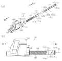
- FIG. 1 is an exploded perspective view of a sunroof device according to a first embodiment.
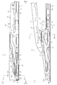
- A is a side view which shows the fully closed state of a movable panel about the sunroof apparatus of FIG. 1
- (b) is a side view which shows the 2nd tilt-up state of a movable panel about the sunroof apparatus of FIG.
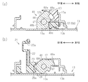
- FIG. 3A is a sectional view taken along line 3A-3A in FIG. 2A
- FIG. 3B is a sectional view taken along line 3B-3B in FIG.
- the side view which shows a guide block and its periphery structure about the sunroof apparatus of FIG.
- the perspective view which shows a guide block and a slide check about the sunroof apparatus of FIG.
- FIG. 5A is an exploded perspective view showing the slide check of FIG. 5 and its peripheral structure
- FIG. 5B is a plan view showing the slide check of FIG. 5 and its peripheral structure
- FIG. 5C is a slide check of FIG.
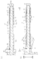
- FIG. 8A is a cross-sectional view taken along line 8A-8A in FIG. 7B
- FIG. 8B is a cross-sectional view taken along line 8B-8B in FIG. 7C.
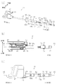
- Explanatory drawing which shows the engagement / disengagement switching mechanism developed in the circumferential direction and shows the operation of the engagement / disengagement switching mechanism.
- the perspective view which shows a rotation prevention main body.
- FIG. 14 is a cross-sectional view taken along line 14-14 in FIG.
- a substantially square opening 10a is formed in a roof 10 of a vehicle such as an automobile, and a sunroof device 11 is mounted.
- the sunroof device 11 includes a substantially rectangular movable panel 12 made of, for example, a glass plate that moves in the front-rear direction to open and close the opening 10a.
- the movable panel 12 is attached so that a tilt-up operation in which the rear part rises with its front part as a fulcrum and a sliding operation in the front-rear direction are possible.
- a so-called outer sliding type is employed in which the movable panel 12 slides while being tilted up.
- a pair of guide rails 13 are disposed at both edges of the opening 10a in the vehicle width direction.
- Each guide rail 13 is made of, for example, an extruded material of an aluminum alloy, has a constant cross section in the longitudinal direction, and extends in the front-rear direction.
- Each guide rail 13 supports a functional component 20 so as to be movable in the front-rear direction.
- the movable panel 12 is linked to and supported by both functional parts 20 in a state of being bridged between them.
- the two functional components 20 cause the movable panel 12 to perform a tilt-up operation or a slide operation in accordance with the movement in the front-rear direction along the guide rail 13.
- both guide rails 13 are connected via a front housing 14 extending in the vehicle width direction.
- An electrical drive source 15 such as an electric motor having an output gear is installed in the middle portion in the longitudinal direction of the front housing 14.
- the electrical drive source 15 is connected to each functional component 20 via each of a pair of substantially belt-like drive belts 16 made of, for example, a resin material, and simultaneously moves both functional components 20 in the front-rear direction.
- each guide rail 13 is formed with a first rail portion 13a having a substantially C-shaped cross section that opens upward, and the first rail portion 13a.
- a second rail portion 13b is formed adjacent to the outside of the vehicle.
- the second rail portion 13b has a substantially L-shaped cross section and communicates with the first rail portion 13a.
- each guide rail 13 is formed with a flange 17 so as to be positioned above the vehicle outside portion of the first rail portion 13a.
- the flange 17 is formed with a substantially rectangular notch 17a.
- the guide block 60 is being fixed to the guide rail 13 so that it may be mounted in the vehicle outer side site
- the guide block 60 is fitted to the flange 17 at the notch 17a.
- the guide block 60 is formed with an engagement groove 60 a that communicates from above to below the flange 17. That is, the engaging groove 60a is inclined downward as it goes rearward, and communicates with the lower space of the flange 17 at its lower end.
- a substantially block-shaped held portion 61 that protrudes toward the vehicle inner side at a position between the first rail portion 13 a and the flange 17 in the vehicle height direction is provided at the front end portion of the guide block 60. Is formed. A rear end surface of the held portion 61 extending in a substantially planar shape forms a contacted surface 61a.
- the drive shoe 21 has a vertical wall portion 22 that extends over substantially the entire length in the front-rear direction, and a protruding wall portion 23 that protrudes from the lower end portion of the vertical wall portion 22 toward the vehicle exterior and extends over the substantially entire length in the front-rear direction. (See FIG. 3B).
- the drive shoe 21 has a plurality (three) of extended pieces 24 that enter the second rail portion 13b located on the vehicle exterior side.
- These extending pieces 24 are connected to the drive belt 16 that slides in the front-rear direction on the second rail portion 13b.
- the drive shoe 21 is moved in the front-rear direction along the first rail portion 13a by the drive belt 16 being moved in the front-rear direction along the guide rail 13 (second rail portion 13b) by the electric drive source 15. .
- the vertical wall portion 22 is formed with a guide groove 22a that is recessed from the vehicle outer end surface toward the vehicle inner side so as to extend in the front-rear direction.
- the guide groove 22a is basically inclined so as to go upward as it goes rearward.
- an engaging recess 26 that is recessed from the vehicle outer end surface toward the vehicle inner side is formed in the longitudinal intermediate portion of the protruding wall portion 23.
- the rear end surface of the engaging recess 26 forms a restricting portion 26a.
- a support bracket 31 extending in the front-rear direction is fixed to the lower surface of the movable panel 12 at each edge in the vehicle width direction.
- the support bracket 31 extends over substantially the entire length of the movable panel 12, has a vertical wall portion 32 made of a metal plate extending downward from the lower surface of the movable panel 12, and mainly the vertical wall portion 32. It has a resin-made molding portion 33 in which the lower edge portion is embedded.
- the support bracket 31 is arranged side by side on the vehicle exterior side with respect to the vertical wall portion 22 so as to be basically disposed above the protruding wall portion 23 of the drive shoe 21.
- a mounting piece 31a extending toward the vehicle interior is formed at the front end of the support bracket 31, and a substantially cylindrical follower shoe 34 is formed at the tip of the mounting piece 31a.
- the follower shoe 34 is mounted in front of the drive shoe 21 so as to be movable in the front-rear direction with respect to the first rail portion 13 a of the guide rail 13.
- the movable panel 12 performs a tilt-up operation, for example, by rotating the support bracket 31 so that the rear part rises with the front part (driven shoe 34) as a fulcrum, and the rear part descends with the front part as a fulcrum. Tilt-down operation is performed by rotating to do.
- the drive shoe 21 and the driven shoe 34 constitute the functional component 20.
- a substantially cylindrical lifting guide pin 35 is integrally provided at the front end portion of the molding portion 33 so as to protrude into the vehicle interior and be movably fitted into the guide groove 22a.
- the elevating guide pin 35 is set to be disposed at the lower end of the guide groove 22a when the movable panel 12 is fully closed. Accordingly, when the drive shoe 21 moves forward by a predetermined distance with respect to the support bracket 31 in this state, the elevating guide pin 35 goes up the guide groove 22a and reaches the middle portion in the longitudinal direction. At this time, the movable bracket 12 performs a tilt-up operation by rotating the support bracket 31 so that the rear part rises with the front part as a fulcrum (first tilt-up state).
- the elevating guide pin 35 further moves up the guide groove 22a to guide the guide groove.
- the end of 22a is reached.
- the movable bracket 12 further performs a tilt-up operation (second tilt-up state) by rotating the support bracket 31 so that the rear part is further raised with the front part as a fulcrum.
- a substantially long cylindrical locking pin 36 that protrudes outward from the vehicle at a position on the front side of the lifting guide pin 35 is integrally provided at the front end portion of the molding portion 33.
- a slide check 41 as a second sliding member made of, for example, a resin material is provided on the guide rail 13 (first rail portion 13 a) adjacent to the outside of the support bracket 31. It is mounted to move in the direction. That is, the slide check 41 includes a shoe portion 42 that slides on the vehicle exterior side portion of the first rail portion 13a, and a vertical wall portion 43 that is positioned between the support bracket 31 and the flange 17 in the vehicle width direction.
- the slide check 41 is positioned in the vehicle width direction by the support bracket 31 and the flange 17 that are in contact with or close to the vertical wall portion 43, and in this state, the shoe portion 42 slides on the vehicle outer side portion of the first rail portion 13a.
- the slide check 41 is movable in the front-rear direction along the guide rail 13.
- a long hole-like allowable hole 43a into which the locking pin 36 is movably fitted is formed in the front side portion of the vertical wall portion 43. .
- the permissible hole 43a is inclined linearly so as to go upward as it goes rearward. That is, the slide check 41 is coupled to the support bracket 31 via the locking pin 36 that is fitted into the allowable hole 43a.
- the slide check 41 allows the movable panel 12 to be tilted (tilt-up operation or tilt-down operation) by causing the locking pin 36 to run idle in the allowable hole 43a.
- the slide check 41 restricts the movement of the locking pin 36 (that is, the support bracket 31) in the front-rear direction through the allowable hole 43a. Accordingly, the slide check 41 moves in the front-rear direction to move the movable panel 12 supported by the support bracket 31 in the front-rear direction integrally with the slide check 41 (slide operation).
- the slide check 41 has a substantially quadrangular column-shaped built-up portion 44 that connects the shoe portion 42 and the vertical wall portion 43 below the flange 17.
- the front end surface spreading in a substantially planar shape of the built-up portion 44 forms a contact surface 44a that faces the contacted surface 61a in the front-rear direction.
- the slide check 41 has a holding piece 45 extending forward from the lower part of the contact surface 44a.
- the holding piece 45 has a substantially square plate-like extension part 45a that extends forward in a cantilevered state from the lower part of the contact surface 44a, and has a substantially triangular claw formed at the front end of the extension part 45a. Part 45b.
- a metal leaf spring 46 is attached to the slide check 41.
- the leaf spring 46 has a substantially flat urging portion 46a extending forward from the lower surface of the claw portion 45b, and has a substantially arcuate curved portion 46b that folds downward and rearward from the front end of the urging portion 46a. Furthermore, it has the leg part 46c extended backward from the lower end of this curved part 46b along the urging
- the leaf spring 46 which is in an approximately elastic return state (free state), abuts or presses against the lower surface of the claw portion 45b at the rear end portion of the urging portion 46a. Thereby, the holding piece 45 is hold
- the contact surface 44 a of the built-up portion 44 is in contact with the contacted surface 61 a of the held portion 61.
- the slide check 41 is restricted from moving forward relative to the guide block 60.
- the extending portion 45 a extends forward along the lower surface of the held portion 61, and the claw portion 45 b is hooked on the front end surface of the held portion 61.
- the holding piece 45 restricts the movement of the slide check 41.
- the holding piece 45 is attached to the leaf spring 46 as depicted by a two-dot chain line in FIG. While the urging portion 46a is elastically deformed, the urging portion 46a is bent and deformed starting from a connection portion with respect to the abutting surface 44a. Thereby, the slide check 41 is allowed to move backward relative to the guide block 60.
- the slide check 41 has a substantially cylindrical support pin 47 having a central axis extending in the front-rear direction.
- the support pin 47 is provided so as not to rotate, and extends rearward from the slide check 41.
- a substantially annular rotation check 48 that is adjacent to the vertical wall portion 43 on the rear side is pivotally supported at the front end portion of the support pin 47.
- a circumferential groove 47a is formed in the support pin 47 in accordance with the position of the rear end of the rotation check 48, and a snap ring 49 is fitted in the circumferential groove 47a.
- the snap ring 49 is for restricting the backward movement of the rotation check 48.
- the rotation check 48 has a substantially serrated engagement protrusion 48a that protrudes radially outward at a predetermined angular position (the upper right angle position in the figure) with the support pin 47 as the center.
- a substantially triangular tooth-shaped pressed portion 48b that protrudes radially outward at a predetermined angular position (lower left angular position in the figure) with the support pin 47 as the center.
- the rotation check 48 is formed with a substantially L-shaped notch 48 c that communicates in the front-rear direction at a predetermined angular position (lower right angular position in the figure) with the support pin 47 as the center.
- the notch 48c extends so as to penetrate the rotation check 48 in the front-rear direction (axial direction).
- the engaging protrusion 48a engages with the engaging groove 60a of the guide block 60 above the flange 17, and the pressed portion 48b is the bottom surface of the first rail portion 13a (see FIG. And the outer surface of the protruding wall portion 23). Therefore, in the fully closed state of the movable panel 12, the rotation check 48 restricts the rotation by the bottom surface of the first rail portion 13a and the like while the engagement protrusion 48a is engaged with the engagement groove 60a of the guide block 60. Has been.
- the engaging recess portion 26 is formed in the protruding wall portion 23 of the drive shoe 21.
- the rotation check 48 is allowed to rotate within the engaging recess 26. Accordingly, when the rotation check 48 moves rearward together with the drive shoe 21 in this state, the rotation check 48 is guided by the engagement protrusion 48a in the engagement groove 60a, so that FIG. 3 (a) to FIG. It turns clockwise as shown by the change to (b). Then, the engaging protrusion 48a enters below the flange 17 so as to be sandwiched between the flange 17 and the first rail portion 13a. Thereby, the rotation of the rotation check 48 is restricted. At the same time, the pressed portion 48 b is engaged with the engagement recess 26. At this time, the pressed portion 48b is disposed on the movement locus in the front-rear direction of the restricting portion 26a of the drive shoe 21.
- the support pin 47 is behind the rotation check 48, for example, a cylindrical holder 51 made of a resin material. It is inserted so as to be movable in the front-rear direction.
- the holder 51 has a substantially cylindrical holding portion 52 having an inner diameter equivalent to the outer diameter of the support pin 47, and is connected to the rear end of the holding portion 52 via an annular step 51 a and is more than the holding portion 52.
- a large-diameter, generally cylindrical spring accommodating portion 53 is provided.
- a pair of engaging pieces 54 are formed in the front end region of the holding portion 52 so as to face each other in the first direction (vehicle width direction).
- Each engagement piece 54 has an arm portion 54a that is cantilevered at the rear end by cutting the holding portion 52 into a substantially U shape, and substantially protrudes outward from the front-rear intermediate portion of the arm portion 54a. It has a triangular engagement claw 54b.
- the engagement claw 54b is inclined so as to approach the arm portion 54a (support pin 47) as it goes forward from the step 54c protruding from the arm portion 54a in the radial direction around the support pin 47 and the tip of the step 54c.
- An inclined surface 54d is formed.
- a pair of regulating pieces 55 are formed in the rear end region of the holding portion 52 so as to face each other in a second direction (vehicle height direction) different from (or orthogonal to) the first direction.
- Each restricting piece 55 has an arm portion 55a that is cantilevered at the front end by cutting the holding portion 52 into a substantially U shape, and has a substantially triangular shape that protrudes outward from an intermediate portion in the front-rear direction of the arm portion 55a. It has a regulation claw 55b.
- the restricting claw 55b has a restricting surface 55c protruding from the arm portion 55a in the radial direction around the support pin 47 and a guide surface 55d inclined so as to approach the arm portion 55a as it goes forward from the tip of the restricting surface 55c.
- the front end region of the holding portion 52 is inserted into a non-rotating main body 56 made of, for example, a resin material so that it cannot rotate but cannot move in the axial direction.
- the non-rotating main body 56 has a substantially cylindrical main body portion 56 a having an inner diameter equivalent to the outer diameter of the holding portion 52, and a portion of the main body portion 56 a facing both the engaging claws 54 b of the holding portion 52.
- a substantially rectangular engagement hole 56b is formed as a pair of engagement recesses (engagement openings).
- the main body portion 56a (the rotation prevention main body 56) is not rotatable with respect to the holding portion 52 and cannot be moved in the axial direction because the both engagement claws 54b are engaged with the both engagement holes 56b. That is, the non-rotating main body 56 moves in the front-rear direction integrally with the holder 51.
- the anti-rotation main body 56 and the holder 51 constitute an anti-rotation member.
- a support pin 47 is inserted behind the snap ring 49 in the front end region of the main body portion 56a located in front of the holding portion 52.
- a substantially square block-like stopper portion 57 projects from the front end region of the main body portion 56a toward the vehicle exterior side. As shown in FIG. 3A, the stopper portion 57 is formed in accordance with the vehicle outer side portion of the first rail portion 13a, and is slidably fitted into the vehicle outer side portion. Further, the vehicle interior side portion of the stopper portion 57 is formed in accordance with the notch 48c of the rotation check 48 in a state where the engaging protrusion 48a is engaged with the engaging groove 60a, and can enter the notch 48c. It has become.
- the stopper portion 57 can enter the rotation locus of the rotation check 48 in a state where the engagement protrusion 48a is engaged with the engagement groove 60a.
- the rotation check 48 enters the notch 48c so that the stopper portion 57 (so-called saddle structure) is fitted, so that the rotation check 48 is held in the vehicle height direction and the rotation from the state is restricted.
- the vehicle interior portion of the stopper portion 57 is in contact with the rear end surface of the rotation check 48 that is allowed to move in the front-rear direction, so that the front entry of the rotation check 48 is restricted.
- a guide surface 57 a that is inclined downward toward the front is formed at the corner of the front upper end of the stopper portion 57.
- the guide surface 57a is for guiding the stopper portion 57 to enter the notch 48c of the rotation check 48 in a state where the engagement protrusion 48a is engaged with the engagement groove 60a.
- a substantially linear rib 57b extending in the front-rear direction is provided on the upper surface of the stopper portion 57 near the main body portion 56a. The rib 57b comes into contact with the surface of the notch 48c when the stopper portion 57 enters the notch 48c.
- the end cap 58 has a substantially cylindrical guide portion 58a having an inner diameter equivalent to the outer diameter of the support pin 47 and an outer diameter equivalent to the inner diameter of the spring accommodating portion 53, and is larger than the outer diameter of the guide portion 58a.
- a retaining portion 58b having a large outer diameter and closing the rear end of the guide portion 58a is provided.
- the end cap 58 is fixed to the support pin 47 at a guide portion 58 a into which the rear end portion of the support pin 47 is inserted.
- a rear end portion of the guide portion 58a is exposed from the spring accommodating portion 53, and a front end portion of the guide portion 58a is inserted into the spring accommodating portion 53. That is, the holder 51 is allowed to move in the front-rear direction with respect to the support pin 47 in a range until the spring accommodating portion 53 contacts the retaining portion 58b.
- a coil spring 59 is wound around the rear end portion of the support pin 47 as an urging member positioned between the annular step 51 a of the holder 51 and the end cap 58.
- the coil spring 59 is compressed in the axial direction (front-rear direction), and urges the holder 51 forward together with the rotation prevention main body 56. Therefore, when the rotation check 48 is in a state of restricting movement in the front-rear direction, the coil spring 59 biases the vehicle interior portion of the stopper portion 57 so as to enter the notch 48c. Further, when the rotation check 48 is allowed to move in the front-rear direction, the coil spring 59 biases the vehicle interior portion of the stopper portion 57 so as to contact the rear end surface of the rotation check 48.
- a rotating cam 71 made of, for example, a resin material is pivotally supported on the holding portion 52 while being positioned between the annular step 51a and the restricting claw 55b.
- the rotating cam 71 has a substantially cylindrical main body portion 72 having an inner diameter equivalent to the outer diameter of the holding portion 52 and an outer diameter equivalent to the outer diameter of the spring accommodating portion 53. It is pivotally supported by the part 52. Accordingly, the axis of the rotating cam 71 coincides with the center axis of the support pin 47. That is, the rotating cam 71 is arranged coaxially with the rotation check 48.
- the rotating cam 71 has a pair of second cam teeth 73 projecting from the outer peripheral surface of the main body 72. These second cam teeth 73 are formed in a substantially isosceles triangle shape having a bottom extending in the front-rear direction, and are disposed so as to face each other in the radial direction centering on the axis of the rotating cam 71.
- a fixed cam 75 made of, for example, a resin material is installed on the drive shoe 21 so as to be coaxial with the rear of the rotating cam 71.
- the fixed cam 75 has a substantially cylindrical first fixed side member 76 and a substantially cylindrical second fixed side member 77 disposed on the side where the slide check 41 is positioned with respect to the first fixed side member 76.
- the drive shoe 21 is in the position shown in FIG. 2A and the fixed cam 75 is separated from the rotating cam 71.
- the drive shoe 21 is in the position shown in FIG.
- the fixed cam 75 constitutes an engagement / disengagement switching mechanism 70 together with the rotating cam 71.
- the engagement / disengagement switching mechanism 70 is configured to switch the engagement state of the rotation cam 71 and the fixed cam 75 from the disengaged state to the engagement state by the pressing action between the rotation cam 71 and the fixed cam 75, or Switching from the 75 engagement state to the disengagement state is performed.
- each second cam tooth 73 has an angular range smaller than a predetermined angular range (90 ° in the present embodiment) in the circumferential direction around the axis of the rotating cam 71 (this embodiment). In the case of 45 °).
- the front end portion (opening end portion) of the first fixed side member 76 is arranged at the predetermined angle (90 °) around the axis thereof and has a plurality of substantially triangular tooth-shaped first portions that are uneven in the axial direction.
- Cam teeth 76a are formed.
- a pair of open portions 77a extending along the axial direction is formed on the inner peripheral portion of the second fixed side member 77 so as to face each other in the radial direction.
- each open portion 77a on the upper side in the drawing is inclined so as to be gradually expanded toward the rear to form a guide portion 77b.
- Each open portion 77a extending over the entire axial length of the second fixed side member 77 extends in an angular range (45 °) equivalent to the first cam teeth 76a in the circumferential direction around the axial line of the fixed cam 75.
- the opening portion 77a including the guide portion 77b extends in the circumferential direction in the predetermined angle range (90 °).
- the rear end portion (opening end portion) of the second fixed side member 77 has a pair of slopes that are inclined forward toward the guide portion 77b from the open portion 77a between the open portions 77a in the circumferential direction.
- a locking portion 77c is formed. Each locking portion 77c extends in the circumferential direction around the axis of the fixed cam 75 within the predetermined angle range (90 °). Further, the tip and the tooth bottom of the first cam teeth 76a are opposed to each locking portion 77c in the front-rear direction (axial direction).
- the tip of the first cam tooth 76a and the root of the locking portion 77c have a predetermined angle phase difference smaller than the predetermined angle range (90 °) with respect to both ends of the locking portion 77c. It is shifted in the circumferential direction with respect to both ends.
- the rotating cam 71 (slide check 41) and the fixed cam 75 are separated from each other in the front-rear direction (for example, the movable panel 12 shifts from the fully closed state to the first tilt-up state).
- the angular position of the second cam teeth 73 is in the forward / backward rotation position that matches the angular position of the opening 77a. Therefore, when the fixed cam 75 is moved forward together with the drive shoe 21 to shift the movable panel 12 to the second tilt-up state, the second cam teeth 73 are moved to the first cam teeth 76a by the opening portions 77a. Is opened, it passes through the opening 77a and is pressed by the first cam teeth 76a.
- the second cam teeth 73 are guided by the first cam teeth 76a and rotate by the above-described phase difference between the locking portion 77c and the first cam teeth 76a.
- the path to the first cam teeth 76a (the retreat path from the first cam teeth 76a to the opening 77a) is closed by the locking portion 77c. .
- the abutment surface 44 a of the slide check 41 abuts against the abutted surface 61 a of the guide block 60, so that the forward movement of the slide check 41 is restricted, and the rotation check 48 is moved forward together with the slide check 41. Movement is restricted. As described above, the movement of the slide check 41 and the rotation check 48 in the front-rear direction is restricted. And the movement to the front-back direction of the support bracket 31 connected with the slide check 41 via the allowance hole 43a etc. is also controlled. As a result, the movable panel 12 is allowed only a tilt-up operation in which the support bracket 31 rotates so that the rear part rises with the front part as a fulcrum.
- the engaging protrusion 48a of the rotation check 48 is engaged with the engaging groove 60a of the guide block 60, but the front end surface of the engaging protrusion 48a is opposed to the front end surface in the front-rear direction. It is in a non-contact state with the opposing surface of 60a (refer FIG. 4). That is, when the slide check 41 and the rotation check 48 are moved forward with respect to the guide block 60, the abutment surface 44a is not held by the contact surface 44a without the front end surface of the engagement protrusion 48a contacting the opposing surface of the engagement groove 60a. It is regulated by abutting on the abutted surface 61 a of 61.
- the rotating cam 71 and the fixed cam 75 in the engagement / disengagement switching mechanism 70 are separated from each other in the front-rear direction.
- the drive shoe 21 is arranged at such a position. Accordingly, when the drive shoe 21 moves rearward in the first tilt-up state of the movable panel 12, the locking pin 36 runs idle in the allowable hole 43a so as to descend along the allowable hole 43a of the slide check 41. At the same time, the elevating guide pin 35 moves down the guide groove 22a and reaches the end of the guide groove 22a. Along with this, the support bracket 31 (elevating guide pin 35) descends with respect to the drive shoe 21. As a result, the movable panel 12 shifts to a fully closed state by performing a tilt-down operation in which the support bracket 31 rotates so that the rear side portion is lowered with the front side portion as a fulcrum.
- the rotational cam 71 and the fixed cam 75 in the engagement / disengagement switching mechanism 70 overlap in the front-rear direction. Therefore, the second cam teeth 73 of the rotating cam 71 are pressed by the first cam teeth 76a through the opening 77a because the path to the first cam teeth 76a is opened by the opening 77a. Then, the second cam teeth 73 are guided by the first cam teeth 76a and rotate by the above-described phase difference between the locking portion 77c and the first cam teeth 76a.
- the engagement protrusion 48a has the engagement groove 60a.
- the engaging protrusion 48a is rotated so as to enter below the flange 17.
- the rotation check 48 is restricted from rotating in this state.
- the rearward movement restriction of the slide check 41 is released, and the rearward movement restriction of the support bracket 31 connected to the slide check 41 via the allowance hole 43a is also released.
- the pressed portion 48b enters the engaging recess 26 and is disposed on the movement locus in the front-rear direction of the restricting portion 26a.
- the rotation check 48 is restricted from rotating in a state where the engaging protrusion 48 a enters below the flange 17 as described above.
- the to-be-pressed part 48b is arrange
- the engagement protrusion 48a is guided to the engagement groove 60a, so that the rotation check 48 is performed. Rotates so as to allow the engaging protrusion 48a to enter toward the upper end of the engaging groove 60a while removing the pressed portion 48b from the engaging recess 26.
- the abutment surface 44a of the slide check 41 abuts against the abutted surface 61a of the guide block 60, so that the forward movement of the slide check 41 is restricted, and the rotation check 48 is moved forward together with the slide check 41. Movement is restricted. Further, forward movement of the support bracket 31 connected to the slide check 41 via the allowable hole 43a and the like is also restricted. At this time, the holding piece 45 is bent and deformed together with the leaf spring 46 starting from the connection portion with respect to the contact surface 44a when the claw portion 45b is pressed against the lower surface of the held portion 61.
- the holding piece 45 is also elastically restored together with the leaf spring 46 as the claw portion 45 b passes through the held portion 61, whereby the claw portion 45 b is caught on the front end surface of the held portion 61. Accordingly, the slide check 41 is slightly restricted from moving backward with respect to the guide block 60 together with the rotation check 48.
- the guide surface 57a of the stopper part 57 abuts on the upper edge of the notch 48c, so that the stopper part 57 enters smoothly into the notch 48c.
- the rotation preventing main body 56 and the like are restricted from moving forward together with the rotating cam 71 by the main body portion 56 a coming into contact with the rear end of the snap ring 49.
- the first cam teeth 76a press the second cam teeth 73, and the second cam teeth 73 It is guided by the one cam tooth 76a and rotates by the above-described phase difference between the locking portion 77c and the first cam tooth 76a.
- the second cam teeth 73 are rotated by the guide portion 77b so as to reach the advancing / retreating position when the fixed cam 75 is moved backward together with the drive shoe 21, and then the second cam teeth 73 are rotated by the opening portion 77a.
- the path to the one cam tooth 76a (retreat path from the first cam tooth 76a) is opened.
- the rotating cam 71 releases the engagement with the second fixed side member 77 (fixed cam 75) while allowing the second cam teeth 73 to pass through the opening 77a. Then, the fixed cam 75 moves rearward together with the drive shoe 21 while leaving the rotating cam 71 and the like.
- the locking pin 36 runs idle through the allowable hole 43a so as to descend along the allowable hole 43a of the slide check 41, and the elevating guide pin 35 is guided so as to descend along the guide groove 22a.
- the movable panel 12 performs a tilt-down operation, and shifts to the fully closed state through the first tilt-up state.
- the slide check 41 is restrained from moving backward together with the rotation check 48 because the backward movement relative to the guide block 60 is slightly restricted by the holding piece 45 or the like.
- the engagement protrusion 48a is engaged with the engagement groove 60a. Rotation of the rotation check 48 in a direction away from the rotation check is suppressed, and the backward movement of the rotation check 48 is also suppressed.
- the rotation of the rotation check 48 in which the protrusion 48a is disengaged from the engagement groove 60a can be suppressed. Then, it is possible to suppress the occurrence of malfunction due to the drive shoe 21 and the slide check 41 moving backward together. For example, it is possible to suppress the occurrence of so-called one-biting, in which only the driving shoe 21 and the slide check 41 on one side are moved together. And the sunroof apparatus 11 of higher quality can be provided.
- a guide surface 57a is formed to guide the entry of. Accordingly, the guide surface 57a allows the detent main body 56 (stopper portion 57) to enter more smoothly on the rotation trajectory of the rotation check 48 in a state where the engagement protrusion 48a is engaged with the engagement groove 60a. it can.
- the rotation check 48 can be further reduced in size by using the notch 48c formed in the rotation check 48 to enter the detent main body 56 on the rotation trajectory of the rotation check 48. As a result, the space required for rotation of the rotation check 48 can be further reduced.
- the engagement / disengagement switching mechanism 70 causes the holder to move to the holder. 51 is moved backward against the biasing force of the coil spring 59. Then, the anti-rotation main body 56 in which the engagement claw 54 b is engaged with the engagement hole 56 b is moved backward integrally with the holder 51, so that the anti-rotation main body 56 is removed from the rotation locus of the rotation check 48.
- the engaging claw 54b can more strongly press the inner wall surface of the engaging hole 56b facing the step 54c located at the rear.
- the leaf spring 46 cooperates with the holding piece 45 to hold the hooked state with the held portion 61, thereby generating the slide check 41. It is possible to suppress the slide check 41 from moving backward together with the rotation check 48 due to the frictional force.
- the holding piece 45 even if the holding piece 45 deteriorates due to the influence of the surrounding environment (high temperature / humidity) or its change, the holding piece 45 is biased by a metal leaf spring 46 that is not easily affected by the change.
- the hooked state with the held portion 61 can be held. That is, by maintaining the posture of the holding piece 45 that holds the held portion 61, the hooked state of the holding piece 45 and the held portion 61, that is, their coupling force can be maintained substantially constant. Accordingly, the above-described frictional force generated in the slide check 41 can be overcome with a stable coupling force between the holding piece 45 and the held portion 61, and the slide check 41 moves rearward together with the rotation check 48. Can be further suppressed.
- the rotation of the rotation check 48 where the engagement protrusion 48a is disengaged from the engagement groove 60a can be further suppressed.
- the occurrence of malfunction due to the drive shoe 21 and the slide check 41 moving backward together can be further suppressed.
- the sunroof device 11 with higher quality can be provided.
- the slide check 141 as the second sliding member includes a shoe portion 142, a vertical wall portion 143, and a built-up portion 144.
- the slide check 141 is provided with a substantially columnar support pin 147 having a central axis O1 extending in the front-rear direction so as not to rotate.
- the support pin 147 extends rearward from the slide check 141. That is, the support pin 147 has a substantially cylindrical embedded portion 147b, a substantially rhombic columnar support portion 147c, and a substantially disc-shaped retaining portion 147d arranged in that order from the front to the rear.
- the support part 147c has the front side support part 147e and the back side support part 147f in the front and back of the circumferential groove 147a, respectively.
- the support pin 147 is non-rotatable with respect to the slide check 141 because the embedded portion 147b and the front end portion of the front support portion 147e are embedded in a portion straddling the vertical wall portion 143 and the built-up portion 144. ing.
- the support portion 147c has a substantially square shape, and a gently curved portion Cu is formed so that each of the four sides of the square approaches the central axis O1. Further, the support portion 147c forms an arc portion Ar whose corner between the two adjacent sides is centered on the central axis O1.
- the outer diameter of the embedded part 147b is set smaller than the minimum dimension of the support part 147c in the radial direction with respect to the central axis O1
- the outer diameter of the retaining part 147d is the support part 147c in the radial direction with respect to the central axis O1. It is set larger than the maximum dimension.
- the rear end portion of the front support portion 147e extending rearward from the vertical wall portion 143 rotates in a state in which the rearward movement is restricted by the snap ring 49.
- a check 148 is pivotally supported. That is, the rotation check 148 is formed with a circular bearing hole 148d having an inner diameter equivalent to the outer diameter of the arc portion Ar, and the rotation check 148 into which the front support portion 147e is inserted has an arc portion in the bearing hole 148d.
- the front support portion 147e support portion 147c
- a rotating cam 171 is pivotally supported on the rear support portion 147f adjacent to the retaining portion 147d on the front side. That is, the rotating cam 171 is formed with a circular bearing hole 171a having an inner diameter equivalent to the outer diameter of the arc portion Ar, and the rotating cam 171 into which the rear support portion 147f is inserted has an arc shape in the bearing hole 171a. By being in sliding contact with the part Ar, it is possible to rotate around the rear support part 147f (support part 147c).
- a substantially cylindrical collar 181 as an interposed member is supported on the rear side support portion 147f so as not to rotate, adjacent to the rotary cam 171 on the front side. That is, the outer wall surface 181a of the collar 181 has an outer diameter equivalent to the outer diameter of the main body portion 172 of the rotary cam 171, and the inner wall surface 181b has a cross-sectional shape of the rear support portion 147f (support portion 147c). Molded to have a matching cross-sectional shape.
- the collar 181 is not rotatable with respect to the rear support portion 147f by inserting the rear support portion 147f.
- a fitting portion 147g is formed particularly in the front-rear direction range where the collar 181 is located.
- a coil spring 185 is wound around the support pin 147 as an urging member interposed between the snap ring 49 and the collar 181.
- the coil spring 185 is compressed in the axial direction (front-rear direction), and urges the collar 181 toward the rotating cam 171 and urges the rotating cam 171 toward the retaining portion 147d.
- the rotation cam 71 and the rotation prevention main body 56 are assembled to the holder 51 before the holder 51 is assembled to the support pin 47 of the slide check 41. That is, first, the holding portion 52 of the holder 51 is inserted into the rotating cam 71 from the front end side. At this time, the rotating cam 71 gets over both of the engaging pieces 54 while elastically deforming both engaging pieces 54 toward the central axis O1, and gets over the both restricting pieces 55 while elastically deforming both restricting pieces 55 toward the central axis O1.
- the rotary cam 71 can smoothly get over both the engaging claws 54b and the both regulating claws 55b along the inclined surface 54d and the guide surface 55d, respectively. Thereby, the rotating cam 71 is supported by the holding part 52 in a state where the rotating cam 71 is positioned between the annular step 51a and the two restricting claws 55b.
- the holding portion 52 is inserted into the main body portion 56a of the rotation stop main body 56 from the front end side.
- the main body 56a gets over both the engagement pieces 54 while elastically deforming both the engagement pieces 54 toward the central axis O1, and the both engagement holes 56b reach the both restricting claws 55b.
- Both regulating claws 55b are engaged with both engaging holes 56b while returning to elasticity.
- the main body portion 56a can smoothly get over both the engaging claws 54b along the inclined surface 54d.
- the rotating cam 71 is supported by the holding portion 52 so that it cannot rotate but cannot move in the front-rear direction.
- the leaf spring 46 may be omitted. Further, the light holding structure itself by the held portion 61 of the guide block 60 and the holding piece 45 of the slide check 41 may be omitted.
- each engagement claw 54b is an example.
- a step parallel to the step 54c may be provided, and the cross-sectional shape of the engaging claw may be substantially rectangular.
- the said 1st Embodiment may replace with the engagement hole 56b which is a through-hole, and may employ
- at least one of the engaging claws 54b (engaging piece 54) may be omitted.
- a notch 48c is formed in the rotation check 48, and a stopper 57 (rotation main body 56) is inserted into the notch 48c.
- the stopper part 57 was made to enter.
- an appropriate protrusion for engagement may be formed on the rotation check 48, and the stopper portion (anti-rotation main body) may be entered on the rotation trajectory of the protrusion.
- the guide surface 57a is formed on the stopper portion 57.
- the rotation check 48 (notch 48c) is a guide surface according to the guide surface 57a. May be formed.
- the guide surface 57a of the stopper portion 57 may be omitted.
- the fixed cam 75 is disposed on the drive shoe 21 and the rotating cam 71 is disposed on the slide check 41. However, the disposition relationship may be reversed.
- the fitting portion (147g) of the support pin 147 may have a substantially triangular, substantially rectangular, or five or more substantially polygonal columnar shape.
- the collar (181) formed with the inner wall surface (181b) having a cross-sectional shape that matches the cross-sectional shape of the fitting part so that the fitting part is fitted and inserted By adopting, the same effects as those of the second embodiment can be obtained.
- the fitting portion 147g is formed by using a part of the support portion 147c (rear side support portion 147f) having a substantially constant cross section, but the support portion 147c is adapted to the arrangement of the collar 181. You may employ
- the support portion 147c may have a substantially cylindrical shape that can pivotally support the rotation check 148 or the rotation cam 171 except for the range in the front-rear direction where the collar 181 is located.
- the tilted-up state of the movable panel 12 includes a first tilt-up state and a second tilt-up state that is further tilted up than the first tilt-up state.
- the initial tilted-up posture in which the movable panel 12 shifts from the fully closed state may coincide with the tilted-up posture in which the movable panel 12 slides.
- connection mode between the drive shoe 21 and the support bracket 31 is an example.
- a guide groove opposite to the guide groove 22 a may be formed in the support bracket 31 (vertical wall portion 32), and an elevating guide pin that is movably fitted in the guide groove may be fixed to the drive shoe 21.
Landscapes
- Engineering & Computer Science (AREA)
- Mechanical Engineering (AREA)
- Power-Operated Mechanisms For Wings (AREA)
Abstract
サンルーフ装置は、第1及び第2の摺動部材と、係合溝を有するガイドブロックと、係合突部を有して第2の摺動部材に回動自在に連結される回転チェックと、第2の摺動部材に前後方向に移動自在に連結される回り止め部材と、を備える。第1の摺動部材と共に第2の摺動部材が後方に移動するときに、係合突部が係合溝から外れるように回動させられる。回り止め部材は前方への移動に伴い、係合突部が係合溝に係入する状態にある回転チェックの回動軌跡上に進入する。可動パネルの全閉状態において第1の摺動部材が前方への移動に続いて後方に移動するとき、係脱切替機構が、回り止め部材を後方に移動させつつ第2の摺動部材を第1の摺動部材と一体で移動させる。
Description
本発明は、サンルーフ装置に関するものである。
従来、サンルーフ装置としては、例えば特許文献1に記載された、いわゆるアウタスライドサンルーフ装置が知られている。このサンルーフ装置は、車両のルーフに形成された開口を開閉する可動パネルと、開口の車両幅方向における両縁部の各々に設けられるガイドレールと、各ガイドレールに沿って移動自在に設けられて可動パネルの車両幅方向における両縁部の各々に連係された第1の摺動部材(駆動シュー)と、両第1の摺動部材を移動させる電気的駆動源とを備える。また、サンルーフ装置は、第1の摺動部材よりも車両前方で可動パネルの車両幅方向における両縁部の各々に連結されて該可動パネルと一体でガイドレールに沿って移動自在な第2の摺動部材(スライドチェック)を備える。さらに、サンルーフ装置は、各ガイドレールに設けられて係合溝を有するガイドブロック(チェックブロック)と、係合溝に係入可能な係合突部を有して第2の摺動部材に回動自在に連結された回転チェックとを備える。
可動パネルは、全閉状態において第2の摺動部材に対して第1の摺動部材が車両前方に移動するときにチルトアップ状態に移行する。可動パネルはまた、第1の摺動部材が更に車両前方に移動した後に車両後方に移動するときに、第2の摺動部材が第1の摺動部材と一体で移動するようにそれら第1の摺動部材及び第2の摺動部材が係合することで、チルトアップ状態のまま開動作する。
なお、可動パネルの全閉状態では、回転チェックの係合突部がガイドブロックの係合溝に係入しており、第1の摺動部材が車両前方に移動するときには第2の摺動部材の移動が可動パネルと共に規制される。そして、第1の摺動部材が更に車両前方に移動した後に車両後方に移動するときには、係合突部が係合溝から外れるように回動させられて、第2の摺動部材及び可動パネルの前記移動規制が解除される。
一方、可動パネルは、開状態において第1の摺動部材が第2の摺動部材と一体で車両前方に移動するときに、チルトアップ状態のまま閉動作する。可動パネルは、その後に第1の摺動部材が第2の摺動部材との係合を解除しつつ車両後方に移動するときに、全閉状態に移行(復帰)する。
なお、可動パネルの開状態において、可動パネルをチルトアップ状態のまま閉動作させるべく第1の摺動部材が車両前方に移動するときには、該第1の摺動部材が係合突部を押圧するようにこれと係合することで第2の摺動部材が第1の摺動部材と一体で車両前方に移動する。そして、第2の摺動部材の車両前方への移動に伴い係合突部が係合溝に到達すると、係合突部が第1の摺動部材との係合を解除しつつ係合溝に係入されるように回動させられて、第2の摺動部材及び可動パネルの移動が規制される。従って、全閉状態に移行させるべく第1の摺動部材が車両後方に移動するときには、係合突部は、第1の摺動部材との係合を解除した状態となる。
ところで、特許文献1では、可動パネルの開状態において、第2の摺動部材と一体での第1の摺動部材の車両前方への移動に伴い係合突部が係合溝に到達することで、係合突部が第1の摺動部材との係合を解除しつつ係合溝に係入されるように回動させられる。このため、その後に可動パネルを全閉状態に移行させるべく第1の摺動部材が車両後方に移動するときに係合突部が係合溝から外れるように、即ち第1の摺動部材が係合突部と再び係合するように回動させられる可能性がある。これは、第2の摺動部材に対して第1の摺動部材が車両後方に移動するときに、第2の摺動部材を第1の摺動部材と一体で移動させるように該第2の摺動部材に発生する摩擦力に負けて、係合突部が係合溝から外れるためである。また、回転チェックは、係合突部が係合溝に案内される態様で回動する構造であるため、車両後方に力が加わると係合突部の回動を止めることができないためである。この場合、係合状態にある第1の摺動部材及び第2の摺動部材が一体で車両後方に移動することになり、作動不良が発生してしまう。
本発明の目的は、作動不良の発生を抑制できるサンルーフ装置を提供することにある。
上記課題を解決するサンルーフ装置は、車両のルーフに形成された開口を開閉するよう構成される可動パネルと、前記開口の車両幅方向における両縁部にそれぞれ設けられるガイドレールと、前記可動パネルの車両幅方向における両縁部にそれぞれ連係され、電気的駆動源により対応する前記ガイドレールに沿って移動するように駆動される第1の摺動部材と、前記可動パネルと一体でそれぞれ対応する前記ガイドレールに沿って移動自在な第2の摺動部材と、前記ガイドレールにそれぞれ設けられたガイドブロックであって、係合溝を有するガイドブロックと、前記係合溝に係入して対応する前記第2の摺動部材の移動を規制する係合突部をそれぞれ有する回転チェックであって、該回転チェックは車両前後方向に延びる軸線の周りで回動自在であるように対応する前記第2の摺動部材に連結され、前記第1の摺動部材と共に前記第2の摺動部材が車両後方に移動するときに前記係合突部が前記係合溝から外れるように回動させられる回転チェックと、前記回転チェックよりも車両後方でそれぞれ対応する前記第2の摺動部材に前後方向に移動自在に連結される回り止め部材であって、車両前方への移動に伴い、前記係合突部が前記係合溝に係入する状態にある前記回転チェックの回動軌跡上に進入するように構成される回り止め部材と、前記回り止め部材を車両前方に向けて付勢する付勢部材と、前記可動パネルの全閉状態において対応する前記第1の摺動部材が車両前方への移動に続いて車両後方に移動するときに、前記付勢部材の付勢力に抗して対応する前記回り止め部材を車両後方に移動させつつ対応する前記第2の摺動部材を前記第1の摺動部材と一体で移動させるように構成される係脱切替機構と、を備える。
上記課題を解決するサンルーフ装置は、車両のルーフに形成された開口を開閉するよう構成される可動パネルと、前記開口の車両幅方向における両縁部にそれぞれ設けられるガイドレールと、前記可動パネルの車両幅方向における両縁部にそれぞれ連係され、電気的駆動源により対応する前記ガイドレールに沿って移動するように駆動される第1の摺動部材と、前記可動パネルと一体でそれぞれ対応する前記ガイドレールに沿って移動自在な第2の摺動部材と、車両前後方向に延びる中心軸線を有し、それぞれ対応する前記第2の摺動部材から車両後方に向かって延びる支持ピンであって、後端に抜け止め部を有するとともに該抜け止め部よりも車両前方に嵌合部を有する支持ピンと、前記ガイドレールにそれぞれ設けられたガイドブロックであって、係合溝を有するガイドブロックと、前記係合溝に係入して対応する前記第2の摺動部材の移動を規制する係合突部をそれぞれ有する回転チェックであって、該回転チェックは前記支持ピンに回動自在に支持され、前記第1の摺動部材と共に前記第2の摺動部材が車両後方に移動するときに前記係合突部が前記係合溝から外れるように回動させられる回転チェックと、前記抜け止め部に対し車両前方側で隣接して前記支持ピンに回動自在に支持された回転カムと、前記回転カムと同心で前記第1の摺動部材に支持された固定カムであって、前記可動パネルの全閉状態において前記第1の摺動部材が車両前方への移動に続いて車両後方に移動するときに前記第2の摺動部材が前記第1の摺動部材と一体で移動するように、前記固定カムが前記回転カムとの間の押圧作用により、前記回転カムを回動させつつこれと係合する固定カムと、前記回転カムに対し車両前方側で隣接配置されて前記嵌合部に回動不能に支持された介設部材と、前記回転チェックと前記介設部材との間で前記支持ピンに巻回され、前記介設部材を介して前記回転カムを前記抜け止め部に向けて付勢する付勢部材と、を備える。
(第1の実施形態)
以下、サンルーフ装置の第1の実施形態について説明する。なお、以下では、車両前後方向を単に「前後方向」といい、車両前後方向における前方及び後方をそれぞれ単に「前方」及び「後方」といい、車両高さ方向における上方及び下方をそれぞれ単に「上方」及び「下方」という。また、車両幅方向において、車室内方に向かう側を「車内側」といい、車室外方に向かう側を「車外側」という。
以下、サンルーフ装置の第1の実施形態について説明する。なお、以下では、車両前後方向を単に「前後方向」といい、車両前後方向における前方及び後方をそれぞれ単に「前方」及び「後方」といい、車両高さ方向における上方及び下方をそれぞれ単に「上方」及び「下方」という。また、車両幅方向において、車室内方に向かう側を「車内側」といい、車室外方に向かう側を「車外側」という。
図11に示すように、自動車などの車両のルーフ10には、略四角形の開口10aが形成されるとともに、サンルーフ装置11が搭載される。このサンルーフ装置11は、前後方向に移動して開口10aを開閉する、例えばガラス板からなる略四角形の可動パネル12を備える。
可動パネル12は、その前側部位を支点に後側部位が上昇するチルトアップ動作及び前後方向へのスライド動作が可能なように取り付けられている。可動パネル12による開口10aの開閉作動においては、可動パネル12がチルトアップ状態のままスライド動作する、いわゆるアウタースライディング式が採用されている。
次に、可動パネル12の開閉作動等に係るサンルーフ装置11の構造について説明する。
図12に示すように、開口10aの車両幅方向における両縁部には、一対のガイドレール13が配設されている。各ガイドレール13は、例えばアルミニウム合金の押出材からなり、長手方向に一定断面を有して前後方向に延在する。そして、各ガイドレール13には、機能部品20が前後方向に移動可能に支持されている。両機能部品20には、それらの間に橋渡しされる状態で前記可動パネル12が連係及び支持されている。両機能部品20は、ガイドレール13に沿う前後方向への移動に伴い、可動パネル12をチルトアップ動作又はスライド動作させる。
図12に示すように、開口10aの車両幅方向における両縁部には、一対のガイドレール13が配設されている。各ガイドレール13は、例えばアルミニウム合金の押出材からなり、長手方向に一定断面を有して前後方向に延在する。そして、各ガイドレール13には、機能部品20が前後方向に移動可能に支持されている。両機能部品20には、それらの間に橋渡しされる状態で前記可動パネル12が連係及び支持されている。両機能部品20は、ガイドレール13に沿う前後方向への移動に伴い、可動パネル12をチルトアップ動作又はスライド動作させる。
また、両ガイドレール13の前端同士は、車両幅方向に延在するフロントハウジング14を介して連結されている。このフロントハウジング14の長手方向中間部には、例えば出力ギヤを有する電動モータなどの電気的駆動源15が設置されている。この電気的駆動源15は、例えば樹脂材からなる略帯状の一対の駆動ベルト16の各々を介して各機能部品20に連結されており、両機能部品20を同時に前後方向に移動させる。
図3(a)及び図3(b)に示すように、各ガイドレール13には、上方に開口する断面略C字状の第1レール部13aが形成されるとともに、該第1レール部13aの車外側に隣接して第2レール部13bが形成されている。なお、この第2レール部13bは断面略L字状を呈しており、第1レール部13aに通じている。また、各ガイドレール13には、第1レール部13aの車外側部位の上方に位置するようにフランジ17が形成されている。
図1及び図4に示すように、フランジ17には、略四角形の切り欠き17aが形成されている。そして、ガイドレール13には、第1レール部13aの車外側部位に載置されるようにしてガイドブロック60が固定されている。ガイドブロック60は、切り欠き17aにおいてフランジ17に嵌着されている。このガイドブロック60には、フランジ17の上方から下方に通じる係合溝60aが形成されている。すなわち、係合溝60aは、後方に向かうに従い下方に向かうように傾斜しており、その下端でフランジ17の下方空間に通じている。
また、図1に示すように、ガイドブロック60の前端部には、車両高さ方向において第1レール部13aとフランジ17との間の位置で車内側に突出する略ブロック状の被保持部61が形成されている。この被保持部61の略平面状に広がる後端面は、被当接面61aを形成する。
ガイドレール13(第1レール部13a)には、例えば金属板及び樹脂を一体化して形成した第1の摺動部材としての駆動シュー21が前後方向に移動可能に装着されている。この駆動シュー21は、前後方向の略全長に亘って延びる縦壁部22を有するとともに、該縦壁部22の下端部から車外側に突出し且つ前後方向の略全長に亘って延びる突壁部23を有する(図3(b)参照)。また、駆動シュー21は、車外側に位置する第2レール部13b内に進入する複数(3つ)の延出片24を有する。これら延出片24は、第2レール部13bを前後方向に摺動する前記駆動ベルト16に連結されている。駆動シュー21は、電気的駆動源15により駆動ベルト16がガイドレール13(第2レール部13b)に沿って前後方向に移動させられることで、第1レール部13aに沿って前後方向に移動する。
図2(a)及び図2(b)に示すように、縦壁部22には、その車外側端面から車内側に向かって凹むガイド溝22aが前後方向に延びるように形成されている。このガイド溝22aは、基本的に後方に向かうに従い上方に向かうように傾斜している。なお、図3(b)に示すように、突壁部23の長手方向中間部には、その車外側端面から車内側に向かって凹む係入凹部26が形成されている。係入凹部26の後端面は、規制部26aを形成する。
図1に示すように、可動パネル12の下面には、その車両幅方向における各縁部において、前後方向に延在する支持ブラケット31が固着されている。この支持ブラケット31は、可動パネル12の略全長に亘って延在しており、該可動パネル12の下面から下方に延びる金属板からなる縦壁部32を有するとともに、該縦壁部32の主として下縁部を埋設する樹脂製の成形部33を有する。
支持ブラケット31は、基本的に駆動シュー21の突壁部23の上方に配置されるように縦壁部22に対して車外側に並設されている。そして、支持ブラケット31の前端には、車内側に向かって延びる取付片31aが形成されており、該取付片31aの先端には、略円柱状の従動シュー34が形成されている。この従動シュー34は、駆動シュー21の前方で、ガイドレール13の第1レール部13aに対し前後方向に移動可能に装着されている。可動パネル12は、例えば支持ブラケット31が前側部位(従動シュー34)を支点に後側部位が上昇するように回動することでチルトアップ動作するとともに、当該前側部位を支点に後側部位が下降するように回動することでチルトダウン動作する。駆動シュー21及び従動シュー34は機能部品20を構成する。
図2(a)に示すように、成形部33の前端部には、車内側に突出して前記ガイド溝22aに移動自在に嵌入される略円柱状の昇降ガイドピン35が一体的に設けられている。この昇降ガイドピン35は、可動パネル12の全閉状態でガイド溝22aの下端に配置されるように設定されている。従って、この状態で駆動シュー21が支持ブラケット31に対して前方に所定距離だけ移動すると、昇降ガイドピン35がガイド溝22aを上がってその長手方向中間部に達する。このとき、支持ブラケット31が前側部位を支点に後側部位が上昇するように回動することで、可動パネル12がチルトアップ動作をする(第1のチルトアップ状態)。
続いて、駆動シュー21がガイドレール13(第1レール部13a)に沿って前方に更に移動すると、図2(b)に示すように、昇降ガイドピン35がガイド溝22aを更に上がってガイド溝22aの終端に達する。このとき、支持ブラケット31が前側部位を支点に後側部位が更に上昇するように回動することで、可動パネル12が更にチルトアップ動作をする(第2のチルトアップ状態)。
なお、成形部33の前端部には、昇降ガイドピン35よりも前方側の位置で車外側に突出する略長円柱状の係止ピン36が一体的に設けられている。
図1に示すように、ガイドレール13(第1レール部13a)には、支持ブラケット31の車外側に隣接して、例えば樹脂材等からなる第2の摺動部材としてのスライドチェック41が前後方向に移動可能に装着されている。すなわち、スライドチェック41は、第1レール部13aの車外側部位を摺動するシュー部42を有するとともに、車両幅方向において支持ブラケット31とフランジ17との間に位置する縦壁部43を有する。スライドチェック41は、縦壁部43に当接又は近接する支持ブラケット31及びフランジ17により車両幅方向に位置決めされ、この状態で、シュー部42が第1レール部13aの車外側部位を摺動することで、スライドチェック41がガイドレール13に沿って前後方向に移動自在となっている。
図1に示すように、ガイドレール13(第1レール部13a)には、支持ブラケット31の車外側に隣接して、例えば樹脂材等からなる第2の摺動部材としてのスライドチェック41が前後方向に移動可能に装着されている。すなわち、スライドチェック41は、第1レール部13aの車外側部位を摺動するシュー部42を有するとともに、車両幅方向において支持ブラケット31とフランジ17との間に位置する縦壁部43を有する。スライドチェック41は、縦壁部43に当接又は近接する支持ブラケット31及びフランジ17により車両幅方向に位置決めされ、この状態で、シュー部42が第1レール部13aの車外側部位を摺動することで、スライドチェック41がガイドレール13に沿って前後方向に移動自在となっている。
図2(a)及び図2(b)に示すように、縦壁部43の前側部位には、前記係止ピン36が移動自在に嵌入される長孔状の許容孔43aが形成されている。この許容孔43aは、後方に向かうに従い上方に向かうように直線状に傾斜する。つまり、スライドチェック41は、許容孔43aに嵌入する係止ピン36を介して支持ブラケット31に連結されている。スライドチェック41は、許容孔43a内で係止ピン36を空走させることで、可動パネル12のチルト動作(チルトアップ動作又はチルトダウン動作)を許容する。また、スライドチェック41は、可動パネル12のチルト動作が規制されているとき、許容孔43aにて係止ピン36(すなわち、支持ブラケット31)の前後方向の移動を規制する。従って、スライドチェック41は、前後方向に移動することで、支持ブラケット31に支持される可動パネル12をスライドチェック41と一体で前後方向に移動(スライド動作)させる。
また、図5に示すように、スライドチェック41は、フランジ17よりも下方でシュー部42と縦壁部43とを接続する略四半円柱状の肉盛部44を有する。この肉盛部44の略平面状に広がる前端面は、前後方向において被当接面61aに対向する当接面44aを形成する。そして、スライドチェック41は、当接面44aの下部から前方に延びる保持片45を有する。この保持片45は、当接面44aの下部から片持ち支持の状態で前方に延びる略四角板状の延出部45aを有するとともに、該延出部45aの前端に形成された略三角形の爪部45bを有する。
図6に併せ示すように、スライドチェック41には、例えば金属製の板ばね46が装着されている。この板ばね46は、爪部45bの下面から前方に延出する略平板状の付勢部46aを有するとともに、該付勢部46aの前端から下向き後方に折り返す略弓形の湾曲部46bを有し、更に該湾曲部46bの下端から付勢部46aに沿って後方に延びてシュー部42に嵌挿される脚部46cを有する。そして、概ね弾性復帰状態(自由状態)にある板ばね46は、付勢部46aの後端部において爪部45bの下面に当接又は圧接する。これにより、保持片45は、延出部45aが前後方向に沿って延びる姿勢となるように保持される。
ここで、例えば可動パネル12の全閉状態では、肉盛部44の当接面44aが被保持部61の被当接面61aに当接している。これにより、スライドチェック41は、ガイドブロック60に対する前方への移動が規制されている。このとき、保持片45においては、延出部45aが被保持部61の下面に沿って前方に延びるとともに、爪部45bが被保持部61の前端面に引っ掛かる。そして、板ばね46は、付勢部46aにおいて、保持片45が被保持部61を掛止する姿勢を維持する付勢力を発生する。これにより、スライドチェック41は、ガイドブロック60に対する後方への移動が軽微に規制されている。従って、ガイドブロック60に対してスライドチェック41を後方に移動させようとする力が一定レベル以下の場合には、保持片45は、スライドチェック41の当該移動を規制する。一方、ガイドブロック60に対してスライドチェック41を後方に移動させようとする力が一定レベルを超える場合には、図6に2点鎖線で描いたように、保持片45は、板ばね46の付勢部46aを弾性変形させつつ、当接面44aに対する接続部位を起点に曲げ変形させられ、それによって爪部45bが被保持部61の前端面から外れる。これにより、スライドチェック41は、ガイドブロック60に対する後方への移動が許容される。
図7(a)~図7(c)並びに図8(a)及び図8(b)に示すように、スライドチェック41には、前後方向に延びる中心軸線を有する略円柱状の支持ピン47が回動不能に設けられ、該支持ピン47はスライドチェック41から後方に向かって延びている。そして、支持ピン47の前端部には、縦壁部43に対し後方側で隣接する略円環状の回転チェック48が軸支されている。支持ピン47には、回転チェック48の後端の位置に合わせて周溝47aが形成されるとともに、該周溝47aには、スナップリング49が嵌着されている。このスナップリング49は、回転チェック48の後方への移動を規制するためのものである。
図3(a)に示すように、回転チェック48は、支持ピン47を中心とする所定角度位置(図示右上の角度位置)で径方向外側に突出する略鋸歯状の係合突部48aを有するとともに、支持ピン47を中心とする所定角度位置(図示左下の角度位置)で径方向外側に突出する略三角歯状の被押圧部48bを有する。また、回転チェック48には、支持ピン47を中心とする所定角度位置(図示右下の角度位置)で前後方向に連通する略L字の切り欠き48cが形成されている。すなわち、切り欠き48cは、回転チェック48を前後方向(軸方向)に貫くように延びている。そして、例えば可動パネル12の全閉状態において、係合突部48aがフランジ17の上方でガイドブロック60の係合溝60aに係入するとともに、被押圧部48bが第1レール部13aの底面(及び突壁部23の車外側面)に当接又は近接する。従って、可動パネル12の全閉状態では、回転チェック48は、係合突部48aがガイドブロック60の係合溝60aに係入する状態で、第1レール部13aの底面等により回動を規制されている。これにより、回転チェック48の前後方向への移動が規制され、該回転チェック48と共にスライドチェック41の前後方向への移動が規制される。そして、スライドチェック41に許容孔43a等を介して連結された支持ブラケット31の前後方向への移動も規制されることで、可動パネル12は、全閉状態からチルトアップ状態への移行のみが許容される。ガイドブロック60、スライドチェック41及び回転チェック48等は、チェック機構40を構成する。
既述のように、駆動シュー21の突壁部23には、係入凹部26が形成されている。そして、駆動シュー21の前方への移動に伴い、係入凹部26が被押圧部48bに到達すると、回転チェック48は、係入凹部26内で回動が許容される。従って、この状態で、駆動シュー21と共に回転チェック48が後方に移動すると、該回転チェック48は、係合突部48aが係合溝60aに案内されることで、図3(a)から図3(b)への変化で示すように時計回りに回動する。そして、係合突部48aは、フランジ17と第1レール部13aとの間に挟まれるようにフランジ17の下方に進入する。これにより、回転チェック48の回動が規制される。同時に、被押圧部48bは、係入凹部26に係入される。このとき、被押圧部48bは、前記駆動シュー21の規制部26aの前後方向における移動軌跡上に配置される。
図7(a)~図7(c)並びに図8(a)及び図8(b)に示すように、支持ピン47は、回転チェック48の後方で、例えば樹脂材からなる筒状のホルダ51に前後方向に移動自在に挿入されている。このホルダ51は、支持ピン47の外径と同等の内径を有する略円筒状の保持部52を有するとともに、該保持部52の後端に環状段差51aを介して接続されて保持部52よりも大径の略円筒状のスプリング収容部53を有する。
保持部52の前端領域には、第1の方向(車両幅方向)に対向配置された一対の係合片54が形成されている。各係合片54は、保持部52を略U字状に切り込むことで後端において片持ち支持されたアーム部54aを有するとともに、該アーム部54aの前後方向中間部から外向きに突出する略三角形の係合爪54bを有する。この係合爪54bは、支持ピン47を中心とする径方向にアーム部54aから突出する段差54c及び該段差54cの先端から前方に向かうに従いアーム部54a(支持ピン47)に近づくように傾斜する傾斜面54dを形成する。
また、保持部52の後端領域には、前記第1の方向とは異なる(直交する)第2の方向(車両高さ方向)に対向配置された一対の規制片55が形成されている。各規制片55は、保持部52を略U字状に切り込むことで前端において片持ち支持されたアーム部55aを有するとともに、該アーム部55aの前後方向中間部から外向きに突出する略三角形の規制爪55bを有する。この規制爪55bは、支持ピン47を中心とする径方向にアーム部55aから突出する規制面55c及び該規制面55cの先端から前方に向かうに従いアーム部55aに近づくように傾斜するガイド面55dを形成する。
そして、保持部52の前端領域は、例えば樹脂材からなる回り止め本体56に回動不能且つ軸方向移動不能に挿入されている。すなわち、回り止め本体56は、保持部52の外径と同等の内径を有する略円筒状の本体部56aを有しており、保持部52の両係合爪54bに対向する本体部56aの部分には、一対の係合凹部(係合開口)としての略四角形の係合孔56bが形成されている。本体部56a(回り止め本体56)は、両係合孔56bに両係合爪54bが係入されることで、保持部52に対し回動不能且つ軸方向移動不能となっている。つまり、回り止め本体56は、ホルダ51と一体で前後方向に移動する。回り止め本体56及びホルダ51は回り止め部材を構成する。
保持部52の前方に位置する本体部56aの前端領域には、スナップリング49の後方で支持ピン47が挿入されている。そして、本体部56aの当該前端領域には、車外側に向かって略四角ブロック状のストッパ部57が突設されている。図3(a)に示すように、このストッパ部57は、第1レール部13aの車外側部位に合わせて成形されて、該車外側部位に摺動可能に嵌挿されている。また、ストッパ部57の車内側部位は、係合突部48aが係合溝60aに係入する状態にある回転チェック48の切り欠き48cに合わせて成形されて、該切り欠き48c内に進入可能となっている。つまり、ストッパ部57は、係合突部48aが係合溝60aに係入する状態にある回転チェック48の回動軌跡に進入可能となっている。回転チェック48は、切り欠き48c内にストッパ部57(いわゆる閂構造)が嵌合するように進入することで、車両高さ方向に保持されて当該状態からの回動が規制される。一方、ストッパ部57の車内側部位は、前後方向への移動の許容状態にある回転チェック48の後端面に当接することで、該回転チェック48よりも前方への進入が規制される。
なお、図10に示すように、ストッパ部57の前上端の角部には、前方に向かうに従い下方に向かうように傾斜するガイド面57aが形成されている。このガイド面57aは、係合突部48aが係合溝60aに係入する状態にある回転チェック48の切り欠き48c内へのストッパ部57の進入を案内するためのものである。また、ストッパ部57における本体部56a寄りの上面には、前後方向に延在する略線状のリブ57bが突設されている。このリブ57bは、ストッパ部57が切り欠き48c内に進入する状態にあるときに該切り欠き48cの面に線当たりする。
図8(a)及び図8(b)に示すように、本体部56aがスナップリング49の後端に当接するとき、支持ピン47の後端部はホルダ51よりも後方に突出している。そして、支持ピン47の後端部には、エンドキャップ58が装着されている。このエンドキャップ58は、支持ピン47の外径と同等の内径及びスプリング収容部53の内径と同等の外径を有する略円筒状のガイド部58aを有するとともに、該ガイド部58aの外径よりも大きい外径を有してガイド部58aの後端を塞ぐ抜け止め部58bを有する。エンドキャップ58は、支持ピン47の後端部が挿入されるガイド部58aにおいて支持ピン47に固定されている。ガイド部58aの後端部はスプリング収容部53から露出し、ガイド部58aの前端部はスプリング収容部53に挿入されている。つまり、ホルダ51は、スプリング収容部53が抜け止め部58bに当接するまでの範囲で支持ピン47に対する前後方向の移動が許容されている。
なお、支持ピン47の後端部には、ホルダ51の環状段差51aとエンドキャップ58との間に位置する付勢部材としてのコイルスプリング59が巻回されている。このコイルスプリング59は、その軸方向(前後方向)に圧縮されており、ホルダ51を回り止め本体56と共に前方に向けて付勢する。従って、回転チェック48が前後方向への移動の規制状態にあるとき、コイルスプリング59は、ストッパ部57の車内側部位が切り欠き48c内に進入するように付勢する。また、回転チェック48が前後方向への移動の許容状態にあるとき、コイルスプリング59は、ストッパ部57の車内側部位が回転チェック48の後端面に当接するように付勢する。一方、コイルスプリング59の付勢力に抗してホルダ51が回り止め本体56と共に車両後方に移動すると、切り欠き48c内に進入していたストッパ部57の車内側部位が切り欠き48cから抜けて前後方向への移動の規制状態にある回転チェック48の回動軌跡が開放される。
保持部52には、環状段差51aと規制爪55bとの間に位置決めされた状態で、例えば樹脂材からなる回転カム71が軸支されている。この回転カム71は、保持部52の外径と同等の内径及びスプリング収容部53の外径と同等の外径を有する略円筒状の本体部72を有しており、該本体部72において保持部52に軸支されている。従って、回転カム71の軸線は、支持ピン47の中心軸線に一致する。つまり、回転カム71は、回転チェック48と同軸に配置されている。なお、回転カム71は、本体部72の外周面に突設された一対の第2カム歯73を有する。これら第2カム歯73は、前後方向に延びる底辺を有する略二等辺三角形状に成形されており、回転カム71の軸線を中心とする径方向に互いに対向するように配設されている。
一方、図2(a)及び図2(b)に示すように、駆動シュー21には、例えば樹脂材からなる固定カム75が回転カム71の後方でこれと同軸になるように設置されている。この固定カム75は、略円筒状の第1固定側部材76を有するとともに、第1固定側部材76に対しスライドチェック41が位置する側に配置された略円筒状の第2固定側部材77を有する。可動パネル12が少なくとも全閉状態から第1のチルトアップ状態へと移行する際には、駆動シュー21が図2(a)に示す位置にあり、固定カム75は回転カム71から離間されている。また、可動パネル12が第2のチルトアップ状態へと移行する際には、駆動シュー21が図2(b)に示す位置にあり、固定カム75は回転カム71と前後方向の位置が重なっている。固定カム75は、回転カム71と共に係脱切替機構70を構成する。この係脱切替機構70は、回転カム71と固定カム75との間の押圧作用により、回転カム71及び固定カム75の係合解除状態から係合状態への切り替え、あるいは回転カム71及び固定カム75の係合状態から係合解除状態への切り替えを行う。
すなわち、図9に示すように、各第2カム歯73は、回転カム71の軸線を中心とする周方向で、所定角度範囲(本実施形態では90°)よりも小さい角度範囲(本実施形態では45°)に延在する。一方、第1固定側部材76の前端部(開口端部)には、その軸線周りに前記所定角度(90°)ごとに配設され当該軸線方向に凹凸する複数の略三角歯状の第1カム歯76aが形成されている。また、第2固定側部材77の内周部には、その軸線方向に沿って延びる一対の開放部77aが径方向に対向するように形成されている。各開放部77aの図示上側の後端部は、後方に向かうに従い徐々に拡開されるように傾斜してガイド部77bを形成する。第2固定側部材77の軸線方向全長に亘って延びる各開放部77aは、固定カム75の軸線を中心とする周方向で、第1カム歯76aと同等の角度範囲(45°)に延在しており、ガイド部77bを含む開放部77aは、当該周方向で、前記所定角度範囲(90°)に延在する。
さらに、第2固定側部材77の後端部(開口端部)には、前記周方向における両開放部77a間で、開放部77aからガイド部77bに向かうに従い前方に向かうように傾斜する一対の係止部77cが形成されている。各係止部77cは、固定カム75の軸線を中心とする周方向で、前記所定角度範囲(90°)に延在する。また、各係止部77cには、第1カム歯76aの歯先及び歯底が前後方向(軸方向)に対向する。つまり、第1カム歯76aの歯先及び歯底は、係止部77cの両端に対し、前記所定角度範囲(90°)よりも小さい所定角度の位相差を有するように、係止部77cの両端に対し周方向にずれている。
このような構成にあって、回転カム71(スライドチェック41)及び固定カム75が前後方向に互いに離間されている状態(例えば、可動パネル12が全閉状態から第1のチルトアップ状態に移行するまで)では、第2カム歯73の角度位置は、開放部77aの角度位置に一致する進退回動位置にある。従って、可動パネル12を第2のチルトアップ状態に移行させるべく、駆動シュー21と共に固定カム75を前方に移動させると、第2カム歯73は、開放部77aにより第1カム歯76aへの進路が開放されていることで、開放部77aを通過して第1カム歯76aに押圧される。このとき、第2カム歯73は、第1カム歯76aに案内されて、係止部77cと第1カム歯76aとの間の前述の位相差分だけ回動する。これにより、その後、駆動シュー21と共に固定カム75を後方に移動させる際、係止部77cによって第1カム歯76aへの進路(第1カム歯76aから開放部77aへの退路)が閉塞される。
従って、可動パネル12を後方にスライド動作(即ち開作動)させるべく、駆動シュー21と共に固定カム75を後方に移動させると、第2カム歯73が係止部77cによって回動させられるように案内されつつ該係止部77cに係合される。このように回転カム71と固定カム75とが係合することで、スライドチェック41が駆動シュー21と一体で後方に移動する。そして、係止ピン36を介してスライドチェック41に連結された支持ブラケット31も駆動シュー21と一体で後方に移動する。
次に、本実施形態の作用について説明する。
まず、可動パネル12が全閉状態にあるものとする。このとき、回転チェック48は、係合突部48aが前記ガイドブロック60の係合溝60aに係入する状態で、第1レール部13aの底面等により回動規制されている。同時に、コイルスプリング59により前方に付勢されるストッパ部57(回り止め本体56)の車内側部位が切り欠き48c内に進入して回転チェック48の回動を規制している。これにより、回転チェック48の後方への移動が規制され、該回転チェック48と共にスライドチェック41の後方への移動が規制される。また、スライドチェック41の当接面44aがガイドブロック60の被当接面61aに当接することで、スライドチェック41の前方への移動が規制され、該スライドチェック41と共に回転チェック48の前方への移動が規制される。以上により、スライドチェック41及び回転チェック48の前後方向への移動が規制される。そして、スライドチェック41に許容孔43a等を介して連結された支持ブラケット31の前後方向への移動も規制される。その結果、可動パネル12は、支持ブラケット31がその前側部位を支点に後側部位が上昇するように回動するチルトアップ動作のみが許容されている。
まず、可動パネル12が全閉状態にあるものとする。このとき、回転チェック48は、係合突部48aが前記ガイドブロック60の係合溝60aに係入する状態で、第1レール部13aの底面等により回動規制されている。同時に、コイルスプリング59により前方に付勢されるストッパ部57(回り止め本体56)の車内側部位が切り欠き48c内に進入して回転チェック48の回動を規制している。これにより、回転チェック48の後方への移動が規制され、該回転チェック48と共にスライドチェック41の後方への移動が規制される。また、スライドチェック41の当接面44aがガイドブロック60の被当接面61aに当接することで、スライドチェック41の前方への移動が規制され、該スライドチェック41と共に回転チェック48の前方への移動が規制される。以上により、スライドチェック41及び回転チェック48の前後方向への移動が規制される。そして、スライドチェック41に許容孔43a等を介して連結された支持ブラケット31の前後方向への移動も規制される。その結果、可動パネル12は、支持ブラケット31がその前側部位を支点に後側部位が上昇するように回動するチルトアップ動作のみが許容されている。
なおこのとき、回転チェック48の係合突部48aは、ガイドブロック60の係合溝60aに係入するものの、係合突部48aの前端面はその前端面と前後方向において対向する係合溝60aの対向面とは非接触の状態にある(図4参照)。つまり、ガイドブロック60に対するスライドチェック41及び回転チェック48の前方への移動は、係合突部48aの前端面が係合溝60aの対向面に接触することなく、当接面44aが被保持部61の被当接面61aに当接することで規制される。これは、ガイドブロック60に対するスライドチェック41及び回転チェック48の前方への移動を、係合突部48aの前端面を係合溝60aの対向面に接触させることによって規制しようとすると、係合突部48a(回転チェック48)に十分な強度の確保を要するためである。
この状態で、駆動シュー21が前方に移動すると、係止ピン36がスライドチェック41の許容孔43aに沿って上昇するように該許容孔43aを空走するとともに、昇降ガイドピン35がガイド溝22aを上がってガイド溝22aの長手方向中間部に達する。これに伴い、駆動シュー21に対して支持ブラケット31(昇降ガイドピン35)が上昇することで、可動パネル12が第1のチルトアップ状態に移行する。
既述のように、可動パネル12が少なくとも全閉状態から第1のチルトアップ状態へと移行する際には、係脱切替機構70における回転カム71及び固定カム75が前後方向に互いに離間されるような位置に駆動シュー21が配置されている。従って、可動パネル12の第1のチルトアップ状態で、駆動シュー21が後方に移動すると、係止ピン36がスライドチェック41の許容孔43aに沿って下降するように該許容孔43aを空走するとともに、昇降ガイドピン35がガイド溝22aを下がってガイド溝22aの終端に達する。これに伴い、駆動シュー21に対して支持ブラケット31(昇降ガイドピン35)が下降する。その結果、可動パネル12は、支持ブラケット31がその前側部位を支点に後側部位が下降するように回動するチルトダウン動作をして全閉状態に移行する。
一方、可動パネル12の第1のチルトアップ状態で、駆動シュー21が前方に更に移動すると、係止ピン36がスライドチェック41の許容孔43aに沿って更に上昇するように該許容孔43aを空走するとともに、昇降ガイドピン35がガイド溝22aを上がってガイド溝22aの終端に達する。これに伴い、可動パネル12が第2のチルトアップ状態に移行する。また、駆動シュー21の前方への移動に伴い、被押圧部48bに係入凹部26が到達することで、回転チェック48の回動が許容される。
このとき、係脱切替機構70における回転カム71及び固定カム75は、前後方向の位置が重なる。従って、回転カム71の第2カム歯73は、開放部77aにより第1カム歯76aへの進路が開放されていることで、開放部77aを通過して第1カム歯76aに押圧される。そして、第2カム歯73は、第1カム歯76aに案内されて、係止部77cと第1カム歯76aとの間の前述の位相差分だけ回動する。
その後、駆動シュー21が後方に移動すると、回転カム71の第2カム歯73が第2固定側部材77の係止部77cによって回動させられつつ該係止部77cに係合される。このように回転カム71及び固定カム75が互いに係合することで、回転カム71がホルダ51及び回り止め本体56と共にコイルスプリング59の付勢力に抗して後方に移動する。これにより、切り欠き48c内に進入していたストッパ部57の車内側部位が切り欠き48cから抜けることで、回転チェック48の回動軌跡が開放される。同時に、回転チェック48及びスライドチェック41が一体で後方に移動しようとする。
このとき、回転カム71及び固定カム75の係合状態で駆動シュー21が後方に移動するため、ガイドブロック60に対してスライドチェック41を後方に移動させようとする力が一定レベルを超えることになる。これにより、板ばね46と共に保持片45が弾性変形しつつガイドブロック60(被保持部61)の保持を解除することで、スライドチェック41が回転チェック48と共に後方に移動可能となる。
これに伴い、回り止め本体56等(回り止め部材)から回動軌跡が開放され且つ係入凹部26内で回動が許容されている回転チェック48は、係合突部48aが係合溝60aに案内されることで、係合突部48aがフランジ17の下方に進入するように回動する。そして、回転チェック48は、この状態で回動を規制される。これにより、スライドチェック41の後方への移動規制が解除され、該スライドチェック41に許容孔43a等を介して連結された支持ブラケット31の後方への移動規制も解除される。同時に、被押圧部48bは、係入凹部26内に進入して、規制部26aの前後方向における移動軌跡上に配置される。
従って、駆動シュー21が後方に移動すると、固定カム75と共に回転チェック48及びスライドチェック41が一体で後方に移動する。このとき、回転チェック48(スライドチェック41)と固定カム75との間の前後方向の距離が一定に保たれることで、駆動シュー21と支持ブラケット31との間の前後方向の距離も一定に保たれる。従って、支持ブラケット31に支持される可動パネル12は、第2のチルトアップ状態のまま後方に移動して、開口10aを開放する。これにより、可動パネル12は開状態となる。なお、可動パネル12の開状態で駆動シュー21の後方への移動が停止すると、回転カム71は、回り止め本体56等(回り止め部材)と共にコイルスプリング59に付勢されて前方に移動しようとする。
可動パネル12の開状態では、回転チェック48は、前述したように係合突部48aがフランジ17の下方に進入する状態で回動を規制されている。そして、被押圧部48bは、規制部26aの前後方向における移動軌跡上に配置されている。従って、この状態で、駆動シュー21が前方に移動すると、規制部26aが被押圧部48bを押圧することで、回転チェック48及びスライドチェック41が駆動シュー21と一体で前方に移動する。これは、可動パネル12の開状態で駆動シュー21が前方に移動する際、回転カム71の第2カム歯73と第1固定側部材76の第1カム歯76aとを前後方向に離間して、該第1カム歯76aが第2カム歯73を押圧することがないようにするためである。この場合であっても、スライドチェック41と固定カム75との間の前後方向の距離が一定に保たれることで、駆動シュー21と支持ブラケット31との間の前後方向の距離も一定に保たれる。従って、支持ブラケット31に支持される可動パネル12は、第2のチルトアップ状態のまま前方に移動して、開口10aを閉鎖する。
可動パネル12の閉作動に伴い、該可動パネル12が第2のチルトアップ状態に移行した当初の状態に近付くと、係合突部48aが係合溝60aに案内されることで、回転チェック48は被押圧部48bを係入凹部26から外しつつ係合突部48aを係合溝60aの上端に向かって進入させるように回動する。
一方、スライドチェック41の当接面44aがガイドブロック60の被当接面61aに当接することで、スライドチェック41の前方への移動が規制され、該スライドチェック41と共に回転チェック48の前方への移動が規制される。そして、スライドチェック41に許容孔43a等を介して連結された支持ブラケット31の前方への移動も規制される。このとき、保持片45は、爪部45bが被保持部61の下面に押圧されることで、当接面44aに対する接続部位を起点に板ばね46と共に曲げ変形させられる。保持片45はまた、爪部45bが被保持部61を通過することに伴って板ばね46と共に弾性復帰し、それによって爪部45bが被保持部61の前端面に引っ掛かる。これにより、スライドチェック41は、回転チェック48と共にガイドブロック60に対して後方へ移動することが軽微に規制される。
この状態で、駆動シュー21が前方に更に移動すると、係入凹部26が被押圧部48bを通過して該被押圧部48bに突壁部23の車外側面が当接又は近接することで、係合突部48aが係合溝60aから外れる方向への回転チェック48の回動も規制される。加えて、コイルスプリング59により前方に移動するように付勢される回り止め本体56(回り止め部材)は、ストッパ部57の車内側部位を切り欠き48c内、すなわち回転チェック48の回動軌跡上に進入させる。このとき、ストッパ部57のガイド面57aが切り欠き48cの上縁に当接することで、該切り欠き48c内へのストッパ部57の進入が円滑化される。そして、回り止め本体56等(回り止め部材)は、本体部56aがスナップリング49の後端に当接することで、回転カム71と共に前方へ移動することが規制される。
前方への移動が規制された回転カム71に対し、固定カム75が前方に更に移動すると、第1カム歯76aが第2カム歯73を押圧することで、該第2カム歯73は、第1カム歯76aに案内されて、係止部77cと第1カム歯76aとの間の前述の位相差分だけ回動する。これにより、第2カム歯73は、その後、駆動シュー21と共に固定カム75を後方に移動させる際に、ガイド部77bによって進退回動位置に到達するように回動させられつつ開放部77aによって第1カム歯76aへの進路(第1カム歯76aからの退路)が開放される。従って、回転カム71は、第2カム歯73を開放部77aに通過させつつ、第2固定側部材77(固定カム75)との係合を解除する。そして、固定カム75は、回転カム71等を残置したまま、駆動シュー21と共に後方に移動する。
このとき、係止ピン36がスライドチェック41の許容孔43aに沿って下降するように該許容孔43aを空走するとともに、昇降ガイドピン35がガイド溝22aに沿って下降するように案内されることで、可動パネル12がチルトダウン動作をし、第1のチルトアップ状態を経て全閉状態に移行する。
なお、回転カム71及び固定カム75の係合解除直後の状態で、駆動シュー21が後方に移動する際、係入凹部26が被押圧部48bに再び到達することで、係合突部48aが係合溝60aから外れる方向への回転チェック48の回動が一時的に許容される。一方、駆動シュー21が後方に移動する際、スライドチェック41に発生する摩擦力によって該スライドチェック41が回転チェック48と共に後方に移動しようとしている。具体的には、チルトダウン動作させるべくガイド溝22aに昇降ガイドピン35が押圧される可動パネル12には、可動パネル12を後方に移動させようとする分力が作用する。そのため、可動パネル12はスライドチェック41(及び回転チェック48)と共に後方に移動しようとしている。あるいは、スライドチェック41が駆動シュー21等に接触した場合にスライドチェック41に発生する摩擦力によっても同様である。
しかしながら、スライドチェック41は、保持片45等によりガイドブロック60に対する後方への移動が軽微に規制されていることで、回転チェック48と共に後方へ移動することが抑制される。加えて、コイルスプリング59により回り止め本体56が前方に付勢された状態で切り欠き48c内にストッパ部57の車内側部位が進入していることで、係合突部48aが係合溝60aから外れる方向への回転チェック48の回動が抑制され、該回転チェック48の後方への移動も抑制される。
以上詳述したように、本実施形態によれば、以下に示す効果が得られるようになる。
(1)本実施形態では、可動パネル12の全閉状態において第1の摺動部材である駆動シュー21が前方への移動に続いて後方に移動すると(第2のチルトアップ状態から転向すると)、係脱切替機構70により回り止め本体56がコイルスプリング59の付勢力に抗して後方に移動させられる。これにより、回り止め本体56が回転チェック48の回動軌跡上から外れる。同時に、係脱切替機構70により第2の摺動部材であるスライドチェック41が駆動シュー21と一体で後方に移動させられることで、回転チェック48の係合突部48aが係合溝60aから外れるように回動させられる。従って、スライドチェック41と一体で後方に移動する可動パネル12が開作動する。
(1)本実施形態では、可動パネル12の全閉状態において第1の摺動部材である駆動シュー21が前方への移動に続いて後方に移動すると(第2のチルトアップ状態から転向すると)、係脱切替機構70により回り止め本体56がコイルスプリング59の付勢力に抗して後方に移動させられる。これにより、回り止め本体56が回転チェック48の回動軌跡上から外れる。同時に、係脱切替機構70により第2の摺動部材であるスライドチェック41が駆動シュー21と一体で後方に移動させられることで、回転チェック48の係合突部48aが係合溝60aから外れるように回動させられる。従って、スライドチェック41と一体で後方に移動する可動パネル12が開作動する。
一方、可動パネル12の開状態において駆動シュー21と一体でのスライドチェック41の前方への移動に伴い、係合突部48aが係合溝60aに到達すると、係合突部48aが係合溝60aに係入するように回転チェック48が回動させられる。同時に、コイルスプリング59により前方に付勢される回り止め本体56が回転チェック48の回動軌跡上に進入してその回動を規制する。従って、この状態で、スライドチェック41を残置したまま駆動シュー21が後方に移動するとき、スライドチェック41に発生する摩擦力によって該スライドチェック41が回転チェック48と共に後方に移動しようとしても、係合突部48aが係合溝60aから外れる回転チェック48の回動を抑制できる。そして、駆動シュー21及びスライドチェック41が一体で後方に移動することによる作動不良の発生を抑制できる。例えば、片側の駆動シュー21及びスライドチェック41のみが一体で後方に移動してしまう、いわゆる片噛みの発生を抑制できる。そして、より高品質なサンルーフ装置11を提供できる。
(2)本実施形態では、回り止め本体56に、係合突部48aが係合溝60aに係入する状態にある回転チェック48の回動軌跡上への回り止め本体56(ストッパ部57)の進入を案内するガイド面57aを形成した。従って、ガイド面57aにより、係合突部48aが係合溝60aに係入する状態にある回転チェック48の回動軌跡上に回り止め本体56(ストッパ部57)をより円滑に進入させることができる。
(3)本実施形態では、回転チェック48に形成した切り欠き48cを利用して回転チェック48の回動軌跡上に回り止め本体56を進入させたことで、回転チェック48をより小型化でき、ひいては回転チェック48の回動に要するスペースをより縮小できる。
(4)本実施形態では、可動パネル12の全閉状態において駆動シュー21が前方への移動に続いて後方に移動すると(第2のチルトアップ状態から転向すると)、係脱切替機構70によりホルダ51がコイルスプリング59の付勢力に抗して後方に移動させられる。そして、係合爪54bが係合孔56bに係入される回り止め本体56がホルダ51と一体で後方に移動させられることで、回り止め本体56は回転チェック48の回動軌跡上から外れる。この場合、係合爪54bは、後方に位置する段差54cでこれに対向する係合孔56bの内壁面をより強力に押圧することができる。
(5)本実施形態では、係脱切替機構70によりスライドチェック41が駆動シュー21と一体で後方に移動させられるときには、保持片45が被保持部61との掛止状態を解除するように保持片45と共に板ばね46が弾性変形して、スライドチェック41の移動を可能にする。つまり、この場合には、保持片45等によってスライドチェック41の移動が阻害されることはない。
一方、スライドチェック41を残置したまま駆動シュー21が後方に移動するときには板ばね46が保持片45と協働して被保持部61との掛止状態を保持することで、スライドチェック41に発生する摩擦力によって該スライドチェック41が回転チェック48と共に後方に移動することを抑制できる。
特に、周囲の環境(高温・湿度)やその変化の影響を受けて保持片45が劣化したとしても、該保持片45は、当該影響を受けにくい金属製の板ばね46に付勢されることで被保持部61との掛止状態を保持できる。つまり、被保持部61を掛止する保持片45の姿勢を維持できることで、保持片45と被保持部61との掛止状態、即ちそれらの結合力を略一定に維持できる。これにより、保持片45と被保持部61との間の安定した結合力で、スライドチェック41に発生する前述の摩擦力に打ち勝つことができ、スライドチェック41が回転チェック48と共に後方に移動することをいっそう抑制できる。そして、係合突部48aが係合溝60aから外れる回転チェック48の回動をいっそう抑制でき、ひいては駆動シュー21及びスライドチェック41が一体で後方に移動することによる作動不良の発生をいっそう抑制できる。例えば、片側の駆動シュー21及びスライドチェック41のみが一体で後方に移動してしまう、いわゆる片噛みの発生をいっそう抑制できる。そして、いっそう高品質なサンルーフ装置11を提供できる。
(6)本実施形態では、ストッパ部57が切り欠き48c内に進入する状態にあるときに、該切り欠き48cに対し、前後方向に線状に延びるリブ57bが線当たり(圧接)することで、係合溝60aに係合突部48aが係入する状態にある回転チェック48の姿勢をより安定化できる。
(第2の実施形態)
以下、サンルーフ装置の第2の実施形態について説明する。なお、第2の実施形態は、第1の実施形態のスライドチェック及びその周辺構造を変更した構成であるため、同様の部分についてはその詳細な説明は省略する。第2の実施形態の構成のうち第1の実施形態と同様の機能を有する構成については、十の位以降の符号を第1の実施形態と同一にしている。
以下、サンルーフ装置の第2の実施形態について説明する。なお、第2の実施形態は、第1の実施形態のスライドチェック及びその周辺構造を変更した構成であるため、同様の部分についてはその詳細な説明は省略する。第2の実施形態の構成のうち第1の実施形態と同様の機能を有する構成については、十の位以降の符号を第1の実施形態と同一にしている。
図13(a)及び図13(b)に示すように、第2の摺動部材としてのスライドチェック141は、シュー部142、縦壁部143及び肉盛部144を有する。そして、スライドチェック141には、前後方向に延びる中心軸線O1を有する略柱状の支持ピン147が回動不能に設けられ、該支持ピン147はスライドチェック141から後方に向かって延びている。すなわち、支持ピン147は、前方から後方に向かってその順番に配置された略円柱状の埋設部147b、略菱形柱状の支持部147c及び略円盤状の抜け止め部147dを有する。そして、支持部147cは、周溝147aの前方及び後方にそれぞれ前側支持部147e及び後側支持部147fを有する。支持ピン147は、縦壁部143及び肉盛部144に跨がる部分に埋設部147bと前側支持部147eの前端部とが埋設されることで、スライドチェック141に対して回動不能となっている。
図14に示すように、断面形状において、支持部147cは略正方形をなし、その正方形の4辺の各々が中心軸線O1に近付くように緩やかな湾曲部Cuを形成している。また、支持部147cは、隣り合う2辺の間の角部が中心軸線O1を中心とする円弧部Arを形成している。なお、埋設部147bの外径は、中心軸線O1に対する径方向における支持部147cの最小寸法よりも小さく設定されており、抜け止め部147dの外径は、中心軸線O1に対する径方向における支持部147cの最大寸法よりも大きく設定されている。
図13(a)及び図13(b)に示すように、縦壁部143から後方に延びる前側支持部147eの後端部には、スナップリング49により後方への移動が規制された状態で回転チェック148が軸支されている。すなわち、回転チェック148には、円弧部Arの外径と同等の内径を有する円形の軸受孔148dが形成されており、前側支持部147eの挿入された回転チェック148は、軸受孔148dにおいて円弧部Arに摺接することで前側支持部147e(支持部147c)の周りを回動可能となっている。
一方、後側支持部147fには、抜け止め部147dに前方側で隣接して、回転カム171が軸支されている。すなわち、回転カム171には、円弧部Arの外径と同等の内径を有する円形の軸受孔171aが形成されており、後側支持部147fの挿入された回転カム171は、軸受孔171aにおいて円弧部Arに摺接することで後側支持部147f(支持部147c)の周りを回動可能となっている。
また、後側支持部147fには、回転カム171に前方側で隣接して、介設部材としての略筒状のカラー181が回動不能に支持されている。すなわち、カラー181の外壁面181aは、回転カム171の本体部172の外径と同等の外径を有しており、内壁面181bは、後側支持部147f(支持部147c)の断面形状に合う断面形状を有するように成形されている。カラー181は、後側支持部147fが嵌挿されることで後側支持部147fに対して回動不能となっている。後側支持部147fにおいて、特にカラー181が位置する前後方向の範囲は、嵌合部147gを形成する。
なお、支持ピン147には、スナップリング49とカラー181との間に介装された付勢部材としてのコイルスプリング185が巻回されている。このコイルスプリング185は、その軸線方向(前後方向)に圧縮されており、カラー181を回転カム171に向けて付勢するとともに、該回転カム171を抜け止め部147dに向けて付勢する。
次に、本実施形態の作用とともに、その効果について説明する。
(1)本実施形態では、可動パネル12の全閉状態において駆動シュー21が前方への移動に続いて後方に移動するとき、係合突部148aが係合溝60aから外れつつ駆動シュー21に係合されるように回転チェック148が回動する。このとき、回転チェック148の回動がスナップリング49及びコイルスプリング185を介してカラー181に伝達されたとしても、嵌合部147gに支持されたカラー181が回動することはない。従って、回転チェック148の回動に合わせて回転カム171が連れ回りすることもなく、作動不良の発生を抑制できる。具体的には、片側の駆動シュー21及びスライドチェック141のみが一体で後方に移動してしまう、いわゆる片噛みの発生を抑制できる。そして、より高品質なサンルーフ装置11を提供できる。
(1)本実施形態では、可動パネル12の全閉状態において駆動シュー21が前方への移動に続いて後方に移動するとき、係合突部148aが係合溝60aから外れつつ駆動シュー21に係合されるように回転チェック148が回動する。このとき、回転チェック148の回動がスナップリング49及びコイルスプリング185を介してカラー181に伝達されたとしても、嵌合部147gに支持されたカラー181が回動することはない。従って、回転チェック148の回動に合わせて回転カム171が連れ回りすることもなく、作動不良の発生を抑制できる。具体的には、片側の駆動シュー21及びスライドチェック141のみが一体で後方に移動してしまう、いわゆる片噛みの発生を抑制できる。そして、より高品質なサンルーフ装置11を提供できる。
(2)本実施形態では、可動パネル12の開状態において駆動シュー21と一体でのスライドチェック41の前方への移動に伴い、係合突部148aが係合溝60aに到達すると、係合突部148aが駆動シュー21との係合を解除しつつ係合溝60aに係入されるように回転チェック148が回動する。このとき、回転チェック148の回動がスナップリング49及びコイルスプリング185を介してカラー181に伝達されたとしても、嵌合部147gに支持されたカラー181が回動することはない。従って、回転チェック148の回動に合わせて回転カム171が連れ回りすることもなく、作動不良の発生を抑制できる。具体的には、片側の駆動シュー21及びスライドチェック141のみが一体で後方に移動してしまう、いわゆる片噛みの発生を抑制できる。そして、より高品質なサンルーフ装置11を提供できる。
なお、上記実施形態は以下のように変更してもよい。
・前記第1の実施形態において、ホルダ51に対する回転カム71及び回り止め本体56の組付けは、スライドチェック41の支持ピン47にホルダ51を組み付ける前に行うことが好ましい。すなわち、まず、回転カム71にホルダ51の保持部52を前端側から挿入する。この際、回転カム71は、両係合片54を中心軸線O1に向かって弾性変形させつつこれを乗り越えるとともに、両規制片55を中心軸線O1に向かって弾性変形させつつこれを乗り越える。特に、回転カム71は、両係合爪54b及び両規制爪55bをそれぞれ傾斜面54d及びガイド面55dに沿って円滑に乗り越えることができる。これにより、回転カム71は、環状段差51aと両規制爪55bとの間に位置決めされた状態で保持部52に支持される。
・前記第1の実施形態において、ホルダ51に対する回転カム71及び回り止め本体56の組付けは、スライドチェック41の支持ピン47にホルダ51を組み付ける前に行うことが好ましい。すなわち、まず、回転カム71にホルダ51の保持部52を前端側から挿入する。この際、回転カム71は、両係合片54を中心軸線O1に向かって弾性変形させつつこれを乗り越えるとともに、両規制片55を中心軸線O1に向かって弾性変形させつつこれを乗り越える。特に、回転カム71は、両係合爪54b及び両規制爪55bをそれぞれ傾斜面54d及びガイド面55dに沿って円滑に乗り越えることができる。これにより、回転カム71は、環状段差51aと両規制爪55bとの間に位置決めされた状態で保持部52に支持される。
続いて、回り止め本体56の本体部56aに保持部52を前端側から挿入する。この際、本体部56aは、両係合片54を中心軸線O1に向かって弾性変形させつつこれを乗り越えるとともに、両係合孔56bが両規制爪55bに到達することで両係合片54を弾性復帰させつつ両係合孔56bに両規制爪55bを係入させる。特に、本体部56aは、両係合爪54bを傾斜面54dに沿って円滑に乗り越えることができる。これにより、回転カム71は、回動不能且つ前後方向に移動不能に保持部52に支持される。
その後、ホルダ51のホルダ51に支持ピン47を挿入することで、両係合片54及び両規制片55の中心軸線O1に向かう弾性変形が規制され、回転カム71及び回り止め本体56がスライドチェック41(支持ピン47)に堅固に固定される。
・前記第1の実施形態において、板ばね46を省略してもよい。また、ガイドブロック60の被保持部61及びスライドチェック41の保持片45による軽微な保持構造自体を省略してもよい。
・前記第1の実施形態において、ホルダ51及び回り止め本体56を一体形成してもよい。
・前記第1の実施形態において、各係合爪54bの形状は一例である。例えば傾斜面54dに代えて、段差54cと平行な段差を設け、係合爪の断面形状を略四角形としてもよい。
・前記第1の実施形態において、各係合爪54bの形状は一例である。例えば傾斜面54dに代えて、段差54cと平行な段差を設け、係合爪の断面形状を略四角形としてもよい。
・前記第1の実施形態において、貫通孔である係合孔56bに代えて、非貫通の係合凹部(係合開口)を採用してもよい。
・前記第1の実施形態において、両係合爪54b(係合片54)の少なくとも一方を省略してもよい。
・前記第1の実施形態において、両係合爪54b(係合片54)の少なくとも一方を省略してもよい。
・前記第1の実施形態においては、回転チェック48に切り欠き48cを形成して、該切り欠き48c内にストッパ部57(回り止め本体56)を挿入するかたちで回転チェック48の回動軌跡上にストッパ部57を進入させた。これに対し、回転チェック48に適宜の係合用の突起を形成して、該突起の回動軌跡上にストッパ部(回り止め本体)を進入させてもよい。
・前記第1の実施形態においては、ストッパ部57にガイド面57aを形成したが、これに代えて、若しくはこれに加えて、回転チェック48(切り欠き48c)にガイド面57aに準じたガイド面を形成してもよい。
・前記第1の実施形態において、ストッパ部57のガイド面57aを省略してもよい。
・前記第1の実施形態においては、駆動シュー21に固定カム75を配設し、スライドチェック41に回転カム71を配設したが、これらの配設関係は互いに逆であってもよい。
・前記第1の実施形態においては、駆動シュー21に固定カム75を配設し、スライドチェック41に回転カム71を配設したが、これらの配設関係は互いに逆であってもよい。
・前記第2の実施形態において、支持ピン147の嵌合部(147g)は、略三角形や略長方形、五以上の略多角形の柱状であってもよい。要は、円柱状以外の嵌合部であれば、該嵌合部が嵌挿されるように嵌合部の断面形状に合う断面形状を有する内壁面(181b)の形成されたカラー(181)を採用することで、前記第2の実施形態と同様の効果が得られる。
・前記第2の実施形態においては、断面略一定の支持部147c(後側支持部147f)の一部を利用して嵌合部147gを形成したが、カラー181の配置に合わせて支持部147cの断面形状とは異なる断面形状の嵌合部を採用してもよい。換言すれば、支持部147cにおいて、カラー181が位置する前後方向の範囲以外は、回転チェック148又は回転カム171を軸支可能な略円柱状であってもよい。
・前記各実施形態においては、可動パネル12のチルトアップ状態は、第1のチルトアップ状態と該第1のチルトアップ状態よりも更にチルトアップさせた第2のチルトアップ状態とを含む。これに対し、可動パネル12が全閉状態から移行する当初のチルトアップ状態の姿勢と、可動パネル12がスライド動作する際のチルトアップ状態の姿勢とが一致していてもよい。
・前記各実施形態において、駆動シュー21と支持ブラケット31(可動パネル12)との連結態様は一例である。例えば、支持ブラケット31(縦壁部32)にガイド溝22aと逆向きのガイド溝を形成し、該ガイド溝に移動可能に嵌入する昇降ガイドピンを駆動シュー21に固着してもよい。
Claims (9)
- 車両のルーフに形成された開口を開閉するよう構成される可動パネルと、
前記開口の車両幅方向における両縁部にそれぞれ設けられるガイドレールと、
前記可動パネルの車両幅方向における両縁部にそれぞれ連係され、電気的駆動源により対応する前記ガイドレールに沿って移動するように駆動される第1の摺動部材と、
前記可動パネルと一体でそれぞれ対応する前記ガイドレールに沿って移動自在な第2の摺動部材と、
前記ガイドレールにそれぞれ設けられたガイドブロックであって、係合溝を有するガイドブロックと、
前記係合溝に係入して対応する前記第2の摺動部材の移動を規制する係合突部をそれぞれ有する回転チェックであって、該回転チェックは車両前後方向に延びる軸線の周りで回動自在であるように対応する前記第2の摺動部材に連結され、前記第1の摺動部材と共に前記第2の摺動部材が車両後方に移動するときに前記係合突部が前記係合溝から外れるように回動させられる回転チェックと、
前記回転チェックよりも車両後方でそれぞれ対応する前記第2の摺動部材に前後方向に移動自在に連結される回り止め部材であって、車両前方への移動に伴い、前記係合突部が前記係合溝に係入する状態にある前記回転チェックの回動軌跡上に進入するように構成される回り止め部材と、
前記回り止め部材を車両前方に向けて付勢する付勢部材と、
前記可動パネルの全閉状態において対応する前記第1の摺動部材が車両前方への移動に続いて車両後方に移動するときに、前記付勢部材の付勢力に抗して対応する前記回り止め部材を車両後方に移動させつつ対応する前記第2の摺動部材を前記第1の摺動部材と一体で移動させるように構成される係脱切替機構と、を備えた、サンルーフ装置。 - 請求項1に記載のサンルーフ装置において、
前記回転チェック及び前記回り止め部材の少なくとも一方は、前記係合突部が前記係合溝に係入する状態にある前記回転チェックの回動軌跡上への前記回り止め部材の進入を案内するガイド面を有する、サンルーフ装置。 - 請求項1又は2に記載のサンルーフ装置において、
前記回転チェックは、車両前後方向において前記回転チェックを貫くように延びる切り欠きを有し、
前記回り止め部材は、前記切り欠きに挿入されることで前記回転チェックの回動軌跡上に進入する、サンルーフ装置。 - 請求項1~3のいずれか一項に記載のサンルーフ装置において、
前記第2の摺動部材は、車両前後方向に延びる中心軸線を有する支持ピンを有しており、該支持ピンにおいて前記回転チェックを回動自在に支持しており、
前記回り止め部材は、
前記回転チェックよりも車両後方で前後方向に移動自在に前記支持ピンが挿入されるホルダであって、該支持ピンを中心とする径方向に突出する段差と該段差の先端から車両前方に向かうに従い前記支持ピンに近づくように傾斜する傾斜面とを形成する係合爪を有するホルダと、
前記ホルダが挿入される回り止め本体であって、前記係合爪が係入される係合凹部を有し、前記回動軌跡上に進入可能な回り止め本体と、を有し、
前記係脱切替機構は、前記可動パネルの全閉状態において前記第1の摺動部材が車両前方への移動に続いて車両後方に移動するときに、前記付勢部材の付勢力に抗して前記ホルダを車両後方に移動させつつ前記第2の摺動部材を前記第1の摺動部材と一体で移動させるように構成される、サンルーフ装置。 - 請求項1~4のいずれか一項に記載のサンルーフ装置において、
前記ガイドブロックに形成された被保持部と、
前記第2の摺動部材に設けられた保持片と、
前記第2の摺動部材に装着された板ばねと、を備え、
前記係合突部が前記係合溝に係入する状態で、前記保持片が前記被保持部を掛止し、
前記板ばねは、前記保持片が前記被保持部を掛止する姿勢を維持する付勢力を発生するように構成され、
前記係脱切替機構により前記第2の摺動部材が前記第1の摺動部材と一体で車両後方に移動させられるときには、前記板ばねは、前記保持片が前記被保持部との掛止状態を解除するように前記保持片と共に弾性変形して前記第2の摺動部材の移動を許容し、
前記第2の摺動部材を残置したまま前記第1の摺動部材が車両後方に移動するときには、前記板ばねは、前記保持片と協働して該保持片と前記被保持部との掛止状態を保持する、サンルーフ装置。 - 車両のルーフに形成された開口を開閉するよう構成される可動パネルと、
前記開口の車両幅方向における両縁部にそれぞれ設けられるガイドレールと、
前記可動パネルの車両幅方向における両縁部にそれぞれ連係され、電気的駆動源により対応する前記ガイドレールに沿って移動するように駆動される第1の摺動部材と、
前記可動パネルと一体でそれぞれ対応する前記ガイドレールに沿って移動自在な第2の摺動部材と、
車両前後方向に延びる中心軸線を有し、それぞれ対応する前記第2の摺動部材から車両後方に向かって延びる支持ピンであって、後端に抜け止め部を有するとともに該抜け止め部よりも車両前方に嵌合部を有する支持ピンと、
前記ガイドレールにそれぞれ設けられたガイドブロックであって、係合溝を有するガイドブロックと、
前記係合溝に係入して対応する前記第2の摺動部材の移動を規制する係合突部をそれぞれ有する回転チェックであって、該回転チェックは前記支持ピンに回動自在に支持され、前記第1の摺動部材と共に前記第2の摺動部材が車両後方に移動するときに前記係合突部が前記係合溝から外れるように回動させられる回転チェックと、
前記抜け止め部に対し車両前方側で隣接して前記支持ピンに回動自在に支持された回転カムと、
前記回転カムと同心で前記第1の摺動部材に支持された固定カムであって、前記可動パネルの全閉状態において前記第1の摺動部材が車両前方への移動に続いて車両後方に移動するときに前記第2の摺動部材が前記第1の摺動部材と一体で移動するように、前記固定カムが前記回転カムとの間の押圧作用により、前記回転カムを回動させつつこれと係合する固定カムと、
前記回転カムに対し車両前方側で隣接配置されて前記嵌合部に回動不能に支持された介設部材と、
前記回転チェックと前記介設部材との間で前記支持ピンに巻回され、前記介設部材を介して前記回転カムを前記抜け止め部に向けて付勢する付勢部材と、を備えた、サンルーフ装置。 - 請求項6に記載のサンルーフ装置において、
前記回転チェックは、前記可動パネルの開状態において前記第1の摺動部材と一体での前記第2の摺動部材の車両前方への移動に伴い、前記係合溝に到達した前記係合突部が前記係合溝に係入するように回動させられ、
前記係合突部が前記係合溝に係入することに伴い移動の規制された状態の前記第2の摺動部材に対して前記第1の摺動部材が車両前方への移動に続いて車両後方に移動するときに、前記固定カムが前記回転カムとの間の押圧作用により、前記回転カムを回動させつつこれとの係合を解除する、サンルーフ装置。 - 車両のルーフに形成された開口を開閉するよう構成される可動パネルと、
前記開口の車両幅方向における両縁部にそれぞれ前後方向に延びるように設けられるガイドレールと、
前記可動パネルの車両幅方向における両縁部にそれぞれ連係され、電気的駆動源により対応する前記ガイドレールに沿って移動するように駆動される第1の摺動部材と、
対応する前記第1の摺動部材よりも車両前方に配置され、前記可動パネルのチルト作動を許容する状態で該可動パネルと一体でそれぞれ対応する前記ガイドレールに沿って移動自在な第2の摺動部材と、
前記ガイドレールにそれぞれ設けられたガイドブロックであって、係合溝を有するガイドブロックと、
前記係合溝に係入するように構成された係合突部をそれぞれ有する回転チェックであって、車両前後方向に延びる軸線の周りで回動自在であるように対応する前記第2の摺動部材に連結される回転チェックと、
前記回転チェックよりも車両後方でそれぞれ対応する前記第2の摺動部材に前後方向に移動自在に連結される回り止め部材であって、車両前方への移動に伴い、前記係合突部が前記係合溝に係入する状態にある前記回転チェックの回動軌跡上に進入するように構成される回り止め部材と、
前記回り止め部材を車両前方に向けて付勢する付勢部材と、を備え、
前記可動パネルの全閉状態では前記係合突部が前記係合溝に係入し、それによって、前記第1の摺動部材が車両前方に移動するときに前記可動パネルがチルトアップ状態に移行するよう、前記第2の摺動部材の移動が規制され、
続いて前記第1の摺動部材が更に車両前方に移動した後に車両後方に移動するときに、前記可動パネルが前記チルトアップ状態のまま開作動するよう、前記係合突部が前記係合溝から外れるように回動させられて前記第2の摺動部材の移動規制が解除され、
前記可動パネルの開状態において、前記第1の摺動部材が車両前方に移動するときに、前記可動パネルが前記チルトアップ状態のまま閉作動するよう、前記回転チェックが前記第1の摺動部材との係合により前記第2の摺動部材を車両前方に移動させ、これに伴い前記係合溝に到達した前記係合突部が前記係合溝に係入するように回動させられ、
続いて前記第1の摺動部材が更に車両前方に移動した後に車両後方に移動するときに、前記回転チェックが前記可動パネルを前記全閉状態に移行させるべく前記第2の摺動部材の移動を規制する、サンルーフ装置。 - 車両のルーフに形成された開口を開閉するよう構成される可動パネルと、
前記開口の車両幅方向における両縁部にそれぞれ前後方向に延びるように設けられるガイドレールと、
前記可動パネルの車両幅方向における両縁部にそれぞれ連係され、電気的駆動源により対応する前記ガイドレールに沿って移動するように駆動される第1の摺動部材と、
対応する前記第1の摺動部材よりも車両前方に配置され、前記可動パネルのチルト作動を許容する状態で該可動パネルと一体でそれぞれ対応する前記ガイドレールに沿って移動自在な第2の摺動部材と、
車両前後方向に延びる中心軸線を有し、それぞれ対応する前記第2の摺動部材から車両後方に向かって延びる支持ピンであって、後端に抜け止め部を有するとともに該抜け止め部よりも車両前方に嵌合部を有する支持ピンと、
前記ガイドレールにそれぞれ設けられたガイドブロックであって、係合溝を有するガイドブロックと、
前記係合溝に係入するように構成された係合突部をそれぞれ有する回転チェックであって、前記支持ピンに回動自在に支持される回転チェックと、
前記抜け止め部に対し車両前方側で隣接配置されて前記支持ピンに回動自在に支持された回転カムと、
前記回転カムと同心で前記第1の摺動部材に支持された固定カムと、
前記回転カムに対し車両前方側で隣接配置されて前記嵌合部に回動不能に支持された介設部材と、
前記回転チェックと前記介設部材との間で前記支持ピンに巻回され、前記介設部材を介して前記回転カムを前記抜け止め部に向けて付勢する付勢部材と、を備え、
前記可動パネルの全閉状態では前記係合突部が前記係合溝に係入し、それによって、前記第1の摺動部材が車両前方に移動するときに前記可動パネルがチルトアップ状態に移行するよう、前記第2の摺動部材の移動が規制され、
続いて前記第1の摺動部材が更に車両前方に移動した後に車両後方に移動するときに、前記可動パネルが前記チルトアップ状態のまま開作動するよう、前記係合突部が前記係合溝から外れるように回動させられて前記第2の摺動部材の移動規制が解除され、
前記可動パネルの開状態において、前記第1の摺動部材が車両前方に移動するときに、前記可動パネルが前記チルトアップ状態のまま閉作動するよう、前記回転チェックが前記第1の摺動部材との係合により前記第2の摺動部材を車両前方に移動させ、これに伴い前記係合溝に到達した前記係合突部が前記係合溝に係入するように回動させられ、
続いて前記第1の摺動部材が更に車両前方に移動した後に車両後方に移動するときに、前記回転チェックが前記可動パネルを前記全閉状態に移行させるべく前記第2の摺動部材の移動を規制し、
前記可動パネルの前記チルトアップ状態において、前記第1の摺動部材が更なる車両前方への移動に続いて車両後方に移動するときに前記第2の摺動部材が前記第1の摺動部材と一体で移動するように、前記固定カムが前記回転カムとの間の押圧作用により、前記回転カムを回動させつつこれと係合し、
前記可動パネルの開状態において、前記係合突部が前記係合溝に係入することに伴い移動の規制された状態の前記第2の摺動部材に対して前記第1の摺動部材が車両前方への移動に続いて車両後方に移動するときに、前記固定カムが前記回転カムとの間の押圧作用により、前記回転カムを回動させつつこれとの係合を解除する、サンルーフ装置。
Applications Claiming Priority (2)
| Application Number | Priority Date | Filing Date | Title |
|---|---|---|---|
| JP2016-144375 | 2016-07-22 | ||
| JP2016144375A JP6627676B2 (ja) | 2016-07-22 | 2016-07-22 | サンルーフ装置 |
Publications (1)
| Publication Number | Publication Date |
|---|---|
| WO2018016253A1 true WO2018016253A1 (ja) | 2018-01-25 |
Family
ID=60992158
Family Applications (1)
| Application Number | Title | Priority Date | Filing Date |
|---|---|---|---|
| PCT/JP2017/022545 Ceased WO2018016253A1 (ja) | 2016-07-22 | 2017-06-19 | サンルーフ装置 |
Country Status (2)
| Country | Link |
|---|---|
| JP (1) | JP6627676B2 (ja) |
| WO (1) | WO2018016253A1 (ja) |
Cited By (1)
| Publication number | Priority date | Publication date | Assignee | Title |
|---|---|---|---|---|
| CN111664337A (zh) * | 2020-06-30 | 2020-09-15 | 武汉华星光电半导体显示技术有限公司 | 柔性显示装置 |
Families Citing this family (1)
| Publication number | Priority date | Publication date | Assignee | Title |
|---|---|---|---|---|
| JP7239886B2 (ja) * | 2019-06-28 | 2023-03-15 | 株式会社アイシン | レールガイド装置、及びサンルーフ装置 |
Citations (5)
| Publication number | Priority date | Publication date | Assignee | Title |
|---|---|---|---|---|
| JPS6322726A (ja) * | 1986-07-12 | 1988-01-30 | Daikiyoo Bebasuto Kk | 車両のル−フの作動装置 |
| US5228743A (en) * | 1991-10-07 | 1993-07-20 | Otto Regner | Cam track mount for sunroof |
| US20010019218A1 (en) * | 1999-06-04 | 2001-09-06 | Kiman Lee | Spoiler sunroof |
| JP2015051711A (ja) * | 2013-09-06 | 2015-03-19 | アイシン精機株式会社 | 車両用サンルーフ装置 |
| JP2016032981A (ja) * | 2014-07-31 | 2016-03-10 | アイシン精機株式会社 | サンルーフ装置 |
Family Cites Families (1)
| Publication number | Priority date | Publication date | Assignee | Title |
|---|---|---|---|---|
| KR100996172B1 (ko) * | 2008-07-24 | 2010-11-24 | 주식회사 하이닉스반도체 | 저항성 메모리 소자 및 그 제조 방법 |
-
2016
- 2016-07-22 JP JP2016144375A patent/JP6627676B2/ja active Active
-
2017
- 2017-06-19 WO PCT/JP2017/022545 patent/WO2018016253A1/ja not_active Ceased
Patent Citations (5)
| Publication number | Priority date | Publication date | Assignee | Title |
|---|---|---|---|---|
| JPS6322726A (ja) * | 1986-07-12 | 1988-01-30 | Daikiyoo Bebasuto Kk | 車両のル−フの作動装置 |
| US5228743A (en) * | 1991-10-07 | 1993-07-20 | Otto Regner | Cam track mount for sunroof |
| US20010019218A1 (en) * | 1999-06-04 | 2001-09-06 | Kiman Lee | Spoiler sunroof |
| JP2015051711A (ja) * | 2013-09-06 | 2015-03-19 | アイシン精機株式会社 | 車両用サンルーフ装置 |
| JP2016032981A (ja) * | 2014-07-31 | 2016-03-10 | アイシン精機株式会社 | サンルーフ装置 |
Cited By (2)
| Publication number | Priority date | Publication date | Assignee | Title |
|---|---|---|---|---|
| CN111664337A (zh) * | 2020-06-30 | 2020-09-15 | 武汉华星光电半导体显示技术有限公司 | 柔性显示装置 |
| CN111664337B (zh) * | 2020-06-30 | 2025-04-25 | 武汉华星光电半导体显示技术有限公司 | 柔性显示装置 |
Also Published As
| Publication number | Publication date |
|---|---|
| JP2018012453A (ja) | 2018-01-25 |
| JP6627676B2 (ja) | 2020-01-08 |
Similar Documents
| Publication | Publication Date | Title |
|---|---|---|
| US10919382B2 (en) | Rotary type extension/retraction device | |
| CN107109873A (zh) | 进退移动装置 | |
| WO2016098851A1 (ja) | リッド開閉装置 | |
| JP2010023881A (ja) | 給油口閉鎖装置 | |
| WO2011062193A1 (ja) | 誤給油防止装置 | |
| JP6264792B2 (ja) | 車両用サンルーフ装置 | |
| JP2017154720A (ja) | ハウジングユニット及び開閉体のロック装置 | |
| JP5598282B2 (ja) | 車両用ルーフ装置 | |
| JP2011253655A (ja) | コネクタ | |
| JP2012071717A (ja) | 車両用ルーフ装置 | |
| JP6275176B2 (ja) | パーキング解除ユニット | |
| JP2018012453A (ja) | サンルーフ装置 | |
| US11767693B2 (en) | Lid opening and closing device for a vehicle | |
| JP2015051714A (ja) | 車両用サンルーフ装置 | |
| JP6264793B2 (ja) | 車両用サンルーフ装置 | |
| US11247541B2 (en) | Sunroof device | |
| US5949040A (en) | Turn signal switch | |
| JP2020111903A (ja) | 車両のリッド開閉装置 | |
| JP2009132101A (ja) | タイヤ加硫機のビードリング廻り止め機構 | |
| JP2018188838A (ja) | 車両ドアラッチ装置 | |
| JP4832154B2 (ja) | 燃料タンクの給油口構造 | |
| WO2019167867A1 (ja) | 車両のリッド開閉装置 | |
| JP2010030542A (ja) | 燃料タンクの開閉装置 | |
| JP6327047B2 (ja) | サンルーフ装置 | |
| JP2021006418A (ja) | レールガイド装置、及びサンルーフ装置 |
Legal Events
| Date | Code | Title | Description |
|---|---|---|---|
| 121 | Ep: the epo has been informed by wipo that ep was designated in this application |
Ref document number: 17830773 Country of ref document: EP Kind code of ref document: A1 |
|
| NENP | Non-entry into the national phase |
Ref country code: DE |
|
| 122 | Ep: pct application non-entry in european phase |
Ref document number: 17830773 Country of ref document: EP Kind code of ref document: A1 |