WO2018016235A1 - ベーンポンプ - Google Patents
ベーンポンプ Download PDFInfo
- Publication number
- WO2018016235A1 WO2018016235A1 PCT/JP2017/021816 JP2017021816W WO2018016235A1 WO 2018016235 A1 WO2018016235 A1 WO 2018016235A1 JP 2017021816 W JP2017021816 W JP 2017021816W WO 2018016235 A1 WO2018016235 A1 WO 2018016235A1
- Authority
- WO
- WIPO (PCT)
- Prior art keywords
- rotor
- section
- oil
- vane pump
- pump
- Prior art date
- Legal status (The legal status is an assumption and is not a legal conclusion. Google has not performed a legal analysis and makes no representation as to the accuracy of the status listed.)
- Ceased
Links
Images



Classifications
-
- F—MECHANICAL ENGINEERING; LIGHTING; HEATING; WEAPONS; BLASTING
- F04—POSITIVE - DISPLACEMENT MACHINES FOR LIQUIDS; PUMPS FOR LIQUIDS OR ELASTIC FLUIDS
- F04C—ROTARY-PISTON, OR OSCILLATING-PISTON, POSITIVE-DISPLACEMENT MACHINES FOR LIQUIDS; ROTARY-PISTON, OR OSCILLATING-PISTON, POSITIVE-DISPLACEMENT PUMPS
- F04C18/00—Rotary-piston pumps specially adapted for elastic fluids
- F04C18/30—Rotary-piston pumps specially adapted for elastic fluids having the characteristics covered by two or more of groups F04C18/02, F04C18/08, F04C18/22, F04C18/24, F04C18/48, or having the characteristics covered by one of these groups together with some other type of movement between co-operating members
- F04C18/34—Rotary-piston pumps specially adapted for elastic fluids having the characteristics covered by two or more of groups F04C18/02, F04C18/08, F04C18/22, F04C18/24, F04C18/48, or having the characteristics covered by one of these groups together with some other type of movement between co-operating members having the movement defined in group F04C18/08 or F04C18/22 and relative reciprocation between the co-operating members
- F04C18/344—Rotary-piston pumps specially adapted for elastic fluids having the characteristics covered by two or more of groups F04C18/02, F04C18/08, F04C18/22, F04C18/24, F04C18/48, or having the characteristics covered by one of these groups together with some other type of movement between co-operating members having the movement defined in group F04C18/08 or F04C18/22 and relative reciprocation between the co-operating members with vanes reciprocating with respect to the inner member
-
- F—MECHANICAL ENGINEERING; LIGHTING; HEATING; WEAPONS; BLASTING
- F04—POSITIVE - DISPLACEMENT MACHINES FOR LIQUIDS; PUMPS FOR LIQUIDS OR ELASTIC FLUIDS
- F04C—ROTARY-PISTON, OR OSCILLATING-PISTON, POSITIVE-DISPLACEMENT MACHINES FOR LIQUIDS; ROTARY-PISTON, OR OSCILLATING-PISTON, POSITIVE-DISPLACEMENT PUMPS
- F04C25/00—Adaptations of pumps for special use of pumps for elastic fluids
- F04C25/02—Adaptations of pumps for special use of pumps for elastic fluids for producing high vacuum
-
- F—MECHANICAL ENGINEERING; LIGHTING; HEATING; WEAPONS; BLASTING
- F04—POSITIVE - DISPLACEMENT MACHINES FOR LIQUIDS; PUMPS FOR LIQUIDS OR ELASTIC FLUIDS
- F04C—ROTARY-PISTON, OR OSCILLATING-PISTON, POSITIVE-DISPLACEMENT MACHINES FOR LIQUIDS; ROTARY-PISTON, OR OSCILLATING-PISTON, POSITIVE-DISPLACEMENT PUMPS
- F04C29/00—Component parts, details or accessories of pumps or pumping installations, not provided for in groups F04C18/00 - F04C28/00
- F04C29/02—Lubrication; Lubricant separation
Definitions
- the present invention relates to a vane pump driven by, for example, an automobile engine.
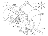
- FIG. 10 shows a perspective exploded sectional view of a conventional vane pump housing and rotor.
- the vane pump 100 includes a housing 101 and a rotor 102.
- the housing 101 includes a pump part 103 and a cylinder part 104.
- a pump chamber 105 is defined inside the pump unit 103.
- An axial (front-rear direction) oil groove 106 is formed on the inner peripheral surface of the cylindrical portion 104.
- the rotor 102 can rotate around a predetermined rotation axis by a driving force from a camshaft (not shown).
- the rotor 102 is made of iron and includes a rotor main body 107 and a shaft portion 108.
- the rotor body 107 is accommodated in the pump chamber 105.
- the rotor main body 107 includes a peripheral wall portion 109 and a bottom wall portion 110.
- the peripheral wall portion 109 includes a pair of rotor groove portions 111.
- the pair of rotor groove portions 111 are arranged to face each other in the diameter direction, that is, to face each other by 180 °.
- the pair of rotor groove portions 111 penetrates the rotor main body 107 (the peripheral wall portion 109 and the bottom wall portion 110) in the diameter direction and the axial direction.
- a pair of rotor grooves 111 accommodates vanes (not shown).
- the shaft portion 108 is accommodated in the cylinder portion 104.
- An axial oil hole 112 and a radial oil hole 113 are formed in the shaft portion 108.
- the oil supply pipe 114 is interposed between the camshaft (not shown) and the rotor 102.
- An oil passage for supplying lubricating oil is set between the camshaft and the pump chamber 105.
- the oil passage includes an oil supply pipe 114, an axial oil hole 112, a radial oil hole 113, an axial oil groove 106, and a rotor groove 111 from the upstream side toward the downstream side.
- Patent Document 1 discloses a vane pump including an oil passage through which lubricating oil is supplied from the radially outer side of the cylindrical portion 104 shown in FIG.
- the oil passage is disposed inside the shaft portion 108 shown in FIG. For this reason, the lubricating oil cannot be sufficiently supplied to the sliding interface between the cylindrical portion 104 and the shaft portion 108 shown in FIG.
- An object of the present invention is to provide a vane pump that can reduce the overall axial length and that can easily supply lubricating oil to the sliding interface at the boundary between the housing and the rotor.
- a vane pump according to the present invention is rotatable about a predetermined rotation axis, a housing having a pump part in which a pump chamber is partitioned, and a cylindrical part connected to the pump part.
- a rotor body that supports a vane disposed in the pump chamber so as to be capable of reciprocating in a diametrical direction, and a shaft portion that is connected to the rotor body and disposed radially inward of the cylindrical portion;
- An oil passage for supplying lubricating oil to the pump chamber wherein the oil passage is disposed in the shaft portion in a radial direction, and is disposed in the shaft portion and downstream of the first portion.
- a second section that is continuous with the first section; and an opening / closing section that is disposed at a boundary between the first section and the second section and that periodically opens and closes the oil passage as the rotor rotates.
- lubricating oil is supplied to the rotor (second section) from the outside in the radial direction (direction orthogonal to the rotation axis direction of the rotor). For this reason, the axial direction full length of a vane pump can be shortened.
- the oil passage has an opening / closing part.
- the opening / closing part can intermittently supply the lubricating oil to the pump chamber as the rotor rotates. For this reason, it can suppress that lubricating oil always flows in into a pump chamber.
- the third section of the oil passage extends along the boundary between the housing and the rotor. For this reason, a 3rd area can be arrange
- FIG. 1 is a radial cross-sectional view of the vane pump of the first embodiment.
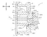
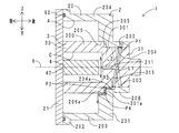
- FIG. 2 is a cross-sectional view in the II-II direction of FIG.
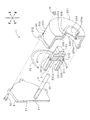
- FIG. 3 is a perspective exploded sectional view of the vane pump.
- FIG. 4 is a perspective view of the rotor of the vane pump.
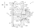
- FIG. 5 is an axial sectional view of the vane pump of the second embodiment.
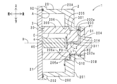
- FIG. 6 is an axial sectional view of the vane pump of the third embodiment.
- FIG. 7 is an axial cross-sectional view of the vane pump of the fourth embodiment.
- FIG. 8 is an axial sectional view of the vane pump of the fifth embodiment.
- FIG. 9 is a perspective view of the vicinity of the bottom wall portion of the housing of the vane pump according to the sixth embodiment.
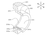
- FIG. 10 is a perspective exploded sectional view of a conventional vane pump housing and rotor.
- FIG. 1 shows a cross-sectional view in the II-II direction of FIG.
- FIG. 3 shows a perspective exploded sectional view of the vane pump.
- FIG. 4 is a perspective view of the rotor of the vane pump. 1 corresponds to a cross section taken along the line II in FIG.
- FIG. 3 corresponds to a cross section in the II-II direction of FIG.
- the vane pump 1 is a negative pressure source of a booster (not shown) of a vehicle brake device. As shown in FIGS. 1 to 4, the vane pump 1 includes a housing 2, a rotor 3, a vane 4, and oil passages L1 and L2.
- the housing 2 is fixed to a side surface of the engine (not shown).
- the housing 2 includes a housing body 20 and an end plate 21.
- the housing body 20 includes a pump part 20A and a cylinder part 20B.
- the pump portion 20A has a bottomed elliptical cylindrical shape that opens to the front side.
- the pump part 20 ⁇ / b> A includes a peripheral wall part 200, a bottom wall part 201, and a flange part 202.
- a pump chamber A is defined inside the pump unit 20A.
- the peripheral wall 200 has an elliptical cylindrical shape. As shown in FIG. 1, a suction hole 200 a is formed in the peripheral wall portion 200. The outlet of the suction hole 200a opens into the pump chamber A.
- the inlet of the suction hole 200a is connected to a booster of the brake device via an intake passage (not shown).
- a check valve (not shown) that allows air flow only in one direction (a direction from the booster toward the pump chamber A) is disposed in the intake passage.
- the bottom wall 201 is disposed at the rear end (one axial end) of the peripheral wall 200.
- the bottom wall 201 is provided with a discharge hole 201a.
- the discharge hole 201a penetrates the bottom wall portion 201 in the front-rear direction.
- the discharge hole 201a can be opened and closed by a reed valve (not shown).
- the flange portion 202 is formed at the front end (the other end in the axial direction) of the peripheral wall portion 200.
- the cylinder portion 20B has a cylindrical shape.
- the cylinder part 20B extends to the rear side of the bottom wall part 201.
- the cylinder portion 20B is accommodated in a recess (not shown) formed in the engine.
- the front end of the cylindrical portion 20B is open to the front surface of the bottom wall portion 201.
- the cylindrical portion 20 ⁇ / b> B includes a radial oil hole 203, a small diameter surface 204, a step surface 205, and a large diameter surface 206.
- the radial oil hole 203 penetrates the cylindrical portion 20B in the radial direction.
- the radial oil hole 203 is included in the concept of the “first section” of the present invention.
- An inlet (radially outer end) of the radial oil hole 203 is connected to an oil passage (not shown) of the engine.
- a small-diameter surface 204, a step surface 205, and a large-diameter surface 206 are formed on the inner peripheral surface of the cylindrical portion 20B from the rear side toward the front side.
- the small diameter surface 204 and the large diameter surface 206 extend in the axial direction (front-rear direction) of the rotation axis X of the rotor 3.
- the step surface 205 extends in the radial direction of the rotation axis X.
- a small diameter side axial oil groove 204 a is recessed in the small diameter surface 204.
- a large-diameter side axial oil groove 206a is recessed in the large-diameter surface 206.
- the end plate 21 seals the flange portion 202 from the front side.
- An O-ring 92 is interposed between the end plate 21 and the flange portion 202.
- the end plate 21 is fixed to the flange portion 202 by a plurality of bolts 90 and a plurality of nuts 91.
- the rotor 3 is made of aluminum and includes a rotor body 30 and a shaft portion 31.
- the rotor body 30 has a bottomed cylindrical shape.
- the rotor body 30 includes a peripheral wall portion 300 and a bottom wall portion 301.
- An in-cylinder space C is defined inside the rotor body 30.
- the peripheral wall 300 has a cylindrical shape.
- the peripheral wall 300 is accommodated in the pump chamber A. As shown in FIG. 1, a part of the outer peripheral surface of the peripheral wall part 300 is in contact with a part of the inner peripheral surface of the peripheral wall part 200.
- the peripheral wall portion 300 is eccentric with respect to the peripheral wall portion 200.
- the front end surface of the peripheral wall portion 300 is in sliding contact with the rear surface (inner surface) of the end plate 21.
- the peripheral wall portion 300 includes a pair of rotor groove portions 300a.
- the pair of rotor groove portions 300a are arranged to face each other in the diameter direction, that is, to face each other by 180 °.
- the pair of rotor groove portions 300a penetrates the peripheral wall portion 300 in the diameter direction. As shown in FIG. 4, the pair of rotor groove portions 300 a does not reach the bottom wall portion 301.
- the bottom wall portion 301 seals the opening on the rear end side of the peripheral wall portion 300.
- the rear surface of the bottom wall 301 is in contact with the step surface 205.
- a pair of radial oil grooves 301 a are formed in the rear surface of the bottom wall portion 301.
- the pair of radial oil grooves 301a are arranged so as to face each other in the diameter direction, that is, 180 degrees.
- the pair of radial oil grooves 301a can communicate with the small-diameter side axial oil groove 204a and the large-diameter side axial oil groove 206a at a predetermined rotation angle (every 180 °).
- the radial oil groove 301a, the small-diameter side axial oil groove 204a, and the large-diameter side axial oil groove 206a are included in the concept of the “third section” of the present invention. As shown in FIG. 4, the radial oil groove 301 a and the rotor groove part 300 a are arranged so as to be shifted by a predetermined angle.
- the shaft portion 31 extends to the rear side of the bottom wall portion 301.
- the shaft portion 31 is connected to a camshaft (not shown) of the engine via a coupling (not shown).
- the shaft part 31 is rotatable around its own axis. That is, the rotor 3 can rotate about the rotation axis X in a predetermined rotation direction ⁇ (counterclockwise direction in FIG. 1).
- the shaft portion 31 includes a radial oil hole 310 and an axial oil hole 311.
- the radial oil hole 310 is included in the concept of the “second section” of the present invention.
- the axial oil hole 311 is included in the concept of “fourth section”.
- the radial oil hole 310 penetrates the shaft portion 31 in the diameter direction.
- the radial oil hole 310 can communicate with the radial oil hole 203 and the small-diameter axial oil groove 204a at a predetermined rotation angle.
- the axial oil hole 311 is interposed between the center of the radial oil hole 310 and the in-cylinder space C.
- the vane 4 includes a vane body 40 and a pair of caps 41.
- the vane body 40 has a rectangular plate shape.
- the vane body 40 is accommodated in the pump chamber A.
- the vane body 40 is rotatable together with the rotor 3.
- the vane body 40 can reciprocate in the diametrical direction along the pair of rotor grooves 300a.
- the vane body 40 can partition the pump chamber A into a plurality of working chambers A1 and A2 according to the rotation angle.
- the front end surface of the vane body 40 is in sliding contact with the rear surface of the end plate 21.
- the rear end surface of the vane body 40 is in sliding contact with the front surface of the bottom wall portion 201.
- a gap is defined between the rear end surface of the vane body 40 and the front surface of the bottom wall portion 301 of the rotor 3.
- the axial oil hole 311 of the shaft portion 31 opens in the gap.
- the oil passage L1 includes a first section (radial oil hole 203), an opening / closing part P1, a second section (radial oil hole 310), an opening / closing part P2, and a third section (small diameter side).
- the opening / closing part P1 is included in the concept of the “opening / closing part” of the present invention.
- the opening / closing parts P1 to P4 can open the oil passage L1 at a predetermined rotation angle. For this reason, the lubricating oil is intermittently supplied to the pump chamber A via the oil passage L1.
- the oil passage L2 has a first section (radial oil hole 203), an opening / closing part P1, a second section (radial oil hole 310), and a fourth section (axial oil hole 311) from the upstream side toward the downstream side. It has.
- the opening / closing part P1 can open the oil passage L2 at a predetermined rotation angle. For this reason, the lubricating oil is intermittently supplied to the in-cylinder space C via the oil passage L2.
- the effect of the vane pump of this embodiment is demonstrated.
- the radial direction (direction orthogonal to the rotation axis X of the rotor 3) with respect to the second section (radial oil hole 310).
- Lubricating oil is supplied from the outside.
- the axial direction (front-back direction) full length of the vane pump 1 can be shortened.
- the oil passage L1 includes opening / closing portions P1 to P4.
- the open / close sections P1 to P4 can intermittently supply the lubricating oil to the pump chamber A as the rotor 3 rotates.
- the third section of the oil passage L1 (small diameter side axial oil groove 204a, opening / closing part P3, radial direction oil groove 301a, opening / closing part P4, large diameter side axial oil groove 206a) is formed between the housing 2 and the rotor 3. It extends along the boundary. For this reason, the third section can be arranged by forming an oil groove in one of the housing 2 and the rotor 3 and sealing the opening of the oil groove on the other side. Therefore, the third section can be easily disposed as compared with the case where the hole-shaped third section is disposed in the housing 2 alone or the rotor 3 alone.
- the third section allows the sliding interface at the boundary between the housing 2 and the rotor 3 (specifically, the sliding interface extending in the axial direction at the boundary between the small diameter surface 204 and the shaft portion 31, the step surface 205 and Lubricating oil is simply supplied to the sliding interface extending in the radial direction at the boundary with the bottom wall 301 and the sliding interface extending in the axial direction at the boundary between the large-diameter surface 206 and the peripheral wall 300. Can do. For this reason, the sliding resistance of the rotor 3 with respect to the housing 2 can be easily reduced.
- the radial oil groove 301 a is disposed in the rotor 3. For this reason, compared with the case where all the 3rd sections are arranged in housing 2, processing of housing 2 becomes easy.
- the rotor 102 is made of iron having a high Young's modulus. For this reason, even if the rotor groove portion 111 (a part of the oil passage) is provided so as to penetrate the bottom wall portion 110 in the axial direction, the strength of the rotor 102 is not easily lowered. On the other hand, when the rotor 102 is made of iron, the vane pump 100 becomes heavy. In this regard, if the rotor 102 is made of aluminum, the vane pump 100 can be reduced in weight. However, aluminum has a low Young's modulus.
- the vane pump 1 of this embodiment in order to make the rotor 3 made of aluminum, the rotor groove portion 300a does not penetrate the bottom wall portion 301 in the axial direction with respect to the conventional rotor 102 shown in FIG. The route of the oil passage has been changed so that it can be completed. If the rotor 3 is made of aluminum, the vane pump 1 can be reduced in weight. Further, the processing of the rotor 3 is easy. Therefore, the processing cost of the rotor 3 can be reduced.
- the radial oil groove 301a (the radial oil groove 301a is shown in FIG.
- the conventional rotor 102 shown in FIG. If the rotor 3 is made of aluminum, the vane pump 1 can be reduced in weight. Further, the processing of the rotor 3 is easy. Therefore, the processing cost of the rotor 3 can be reduced.
- the pressure increases in the vicinity of the discharge hole 201a. That is, the working chamber A2 has a higher pressure than the working chamber A1. For this reason, it is necessary to improve the sealing performance of the working chamber A2 (near the discharge hole 201a). In other words, it is necessary to supply sufficient lubricating oil to the working chamber A2.
- the oil passage L1 shown in FIG. 2 is opened, as shown in FIG. 1, the large-diameter side axial oil groove 206a opens into the working chamber A2 (near the discharge hole 201a). For this reason, compared with the case where the large-diameter side axial oil groove 206a is opened in the working chamber A1 (near the suction hole 200a), the lubricating oil can be sufficiently supplied to the working chamber A2.
- the low pressure working chamber A1, the vane 4, and the high pressure working chamber A2 are arranged from the rear side (suction side) to the front side (discharge side) of the rotor 3 in the rotational direction ⁇ .
- a large-diameter side axial oil groove 206a and a discharge hole 201a are arranged from the rear side in the rotation direction ⁇ of the rotor 3 toward the front side.
- the lubricating oil discharged from the large-diameter side axial oil groove 206a is not directed to the discharge hole 201a on the rotation direction ⁇ front side (high pressure side) but toward the vane 4 on the rotation direction ⁇ rear side (low pressure side) Easy to flow. Therefore, the sealing performance of the working chamber A2 with respect to the working chamber A1 can be enhanced.
- the vane pump 1 of this embodiment is provided with the oil path L2 branched from the oil path L1.
- the opening / closing part P1 can open the oil passage L2 at a predetermined rotation angle.
- the lubricating oil can be intermittently supplied not only to the pump chamber A but also to the in-cylinder space C.
- the oil passage L ⁇ b> 2 opens into the in-cylinder space C of the rotating rotor 3.
- the lubricating oil can be supplied to the sliding interface between the vane body 40 and the rotor groove portion 300a, the sliding interface between the peripheral wall portion 300 and the end plate 21, or the like by utilizing centrifugal force. it can.
- the small-diameter side axial oil groove 204a can be disposed by using the axial oil groove 106 of the conventional vane pump 100 shown in FIG. For this reason, it is easy to divert the conventional housing 101.
- FIG. 5 shows an axial sectional view of the vane pump of this embodiment.
- part corresponding to FIG. 2 it shows with the same code
- a radial oil groove 205 a is recessed in the step surface 205 of the housing 2.
- the radial oil groove 205a is interposed between the small-diameter side axial oil groove 204a and the large-diameter side axial oil groove 206a.
- the vane pump according to the present embodiment and the vane pump according to the first embodiment have the same functions and effects with respect to parts having the same configuration.
- all of the third section (small diameter side axial oil groove 204a, radial direction oil groove 205a, large diameter side axial oil groove 206a) is disposed in the housing 2. . For this reason, it is not necessary to process the rotor 3 regarding the arrangement of the third section.
- FIG. 6 shows an axial sectional view of the vane pump of this embodiment.
- part corresponding to FIG. 5 it shows with the same code
- the shaft portion 31 of the rotor 3 includes an end-like annular oil groove 313 and a radial oil hole 314.
- Ended annular oil groove 313 is included in the concept of the “second section” of the present invention.
- the radial oil hole 314 and the axial oil hole 311 are included in the concept of “fourth section”.
- Ended annular oil groove 313 is recessed in the outer peripheral surface of shaft portion 31.
- the end annular oil groove 313 extends in a C shape in the circumferential direction.
- the end annular oil groove 313 can communicate with the radial oil hole 203 and the small-diameter axial oil groove 204a over a predetermined rotation angle section.
- the radial oil hole 314 is interposed between the end annular oil groove 313 and the axial oil hole 311.
- the vane pump according to the present embodiment and the vane pump according to the second embodiment have the same functions and effects with respect to parts having the same configuration.
- the second section (the end annular oil groove 313) extends in a partial arc shape.
- the opening / closing parts P1 and P2 can open the oil passages L1 and L2 over a predetermined rotation angle section (section corresponding to the extending section of the end annular oil groove 313).
- FIG. 7 shows an axial sectional view of the vane pump of this embodiment.
- the radial oil hole 203 of the cylindrical portion 20B is provided with a closed annular oil groove 203a at the outlet (radial inner end).
- the end annular oil groove 203a extends in a C shape in the circumferential direction on the small diameter surface 204.
- the end annular oil groove 203a can communicate with the axial oil groove 312 over a predetermined rotation angle section.
- the inlet (rear end) of the axial oil groove 312 is included in the concept of the “second section” of the present invention.
- the portion other than the rear end of the axial oil groove 312, the radial oil groove 205 a, and the large-diameter side axial oil groove 206 a are included in the concept of the “third section” of the present invention.
- the radial oil hole 314 is interposed between the end annular oil groove 203 a and the axial oil hole 311.
- the vane pump according to the present embodiment and the vane pump according to the third embodiment have the same functions and effects with respect to parts having the same configuration.
- the end annular oil groove 203a of the first section extends in a partial arc shape. Therefore, the opening / closing parts P1 to P3 can open the oil passages L1 and L2 over a predetermined rotation angle section (section corresponding to the extending section of the end annular oil groove 203a).
- FIG. 8 shows an axial sectional view of the vane pump of this embodiment.
- part corresponding to FIG. 2 it shows with the same code
- inclined oil holes 315 are arranged in the shaft portion 31 instead of the radial oil holes 310 shown in FIG. 2.
- the inclined oil hole 315 is included in the concept of the “second section” of the present invention.
- the inclined oil hole 315 extends in a direction inclined with respect to the radial direction and the axial direction.
- the radial oil hole 310 shown in FIG. 2 connects the radial oil hole 203 and the small-diameter side axial oil groove 204a twice per rotation of the rotor 3 (every 180 °).
- the inclined oil hole 315 shown in FIG. 8 connects the radial oil hole 203 and the small-diameter axial oil groove 204a only once for one rotation of the rotor 3. That is, as shown by a dotted line in FIG. 8, even if the rotor 3 rotates by 180 ° from the state shown in FIG. 8, the inclined oil hole 315 connects the radial oil hole 203 and the small-diameter side axial oil groove 204a. Can not do it.
- the vane pump according to the present embodiment and the vane pump according to the first embodiment have the same functions and effects with respect to parts having the same configuration.
- the opening / closing parts P1 to P4 open the oil passages L1 and L2 only once for one rotation of the rotor 3. For this reason, it is difficult for the lubricating oil to flow backward through the oil passages L1 and L2.
- FIG. 9 is a perspective view of the vicinity of the bottom wall portion of the housing of the vane pump of this embodiment. In addition, about the site
- a backflow suppressing portion 204b is formed on the bottom surface of the small diameter side axial oil groove 204a.
- a backflow suppressing portion 206b is formed on the bottom surface of the large-diameter side axial oil groove 206a.
- the backflow suppressing portions 204b and 206b have a triangular shape that is pointed toward the rear side (upstream side).
- the vane pump according to the present embodiment and the vane pump according to the first embodiment have the same functions and effects with respect to parts having the same configuration.
- the backflow suppression units 204b and 206b are arranged in the third section. For this reason, it is difficult for lubricating oil to flow backward in the oil passage.
- the oil passage L1 includes a first section (for example, the radial oil hole 203 shown in FIG. 2), a second section (for example, the radial oil hole 310 shown in FIG. 2), and a third section (for example, the small-diameter side axial direction shown in FIG. 2).
- the oil passage L2 includes a fourth section (for example, the axial oil hole 311 shown in FIG. 2).
- the cross-sectional area of the flow path from the first section to the fourth section is not particularly limited.
- the flow path cross-sectional area of) may be increased.
- the cross-sectional area of the flow path may not be constant over the entire length of the first section to the fourth section.
- the cross-sectional shape of the first section to the fourth section is not particularly limited. It may be a hole shape, a groove shape (V-shaped groove shape, C-shaped groove shape) or the like.
- the number of arrangements, the number of branches, the position, and the number of openings (exit of the oil passage L1) in the pump chamber A are not particularly limited. For example, what is necessary is just to set the 1st area provided with the inlet_port
- the number and position of the opening / closing parts P1 to P4 are not particularly limited.
- the difference in opening / closing timing of the opening / closing parts P1 to P4 is not particularly limited.
- the opening / closing portions P1 to P4 are arranged upstream of the branch portion between the oil passage L1 and the oil passage L2 (see, for example, the opening / closing portion P1 shown in FIG. 2), the opening and closing timings of the oil passages L1 and L2 are synchronized. Can do.
- the number of times that the opening / closing parts P1 to P4 open and close the oil passages L1 and L2 per one rotation of the rotor 3 is not particularly limited.
- the path of the oil passage is changed so that the rotor groove portion 300a does not have to penetrate the bottom wall portion 301 in the axial direction.
- the materials of the housing 2 and the rotor 3 are not particularly limited.
- it may be made of a metal containing iron (iron, stainless steel, etc.) or a metal containing aluminum (aluminum, aluminum alloy, etc.).
- the strength can be increased as compared with the conventional rotor 102 shown in FIG. 10.
- the manufacturing method of the housing 2 and the rotor 3 is not specifically limited.
- the housing 2 and the rotor 3 may be manufactured by casting, forging, or the like.
Landscapes
- Engineering & Computer Science (AREA)
- Mechanical Engineering (AREA)
- General Engineering & Computer Science (AREA)
- Rotary Pumps (AREA)
- Applications Or Details Of Rotary Compressors (AREA)
Abstract
ベーンポンプ(1)は、ポンプ部(20A)と筒部(20B)とを有するハウジング(2)と、ポンプ部(20A)のポンプ室(A)に配置されるベーン(4)を支持するロータ本体(30)と、筒部(20B)の内側に配置される軸部(31)と、を有するロータ(3)と、ポンプ室(A)に潤滑油を供給する油路(L1)と、を備える。油路(L1)は、筒部(20B)を径方向に貫通する第一区間(203)と、軸部(31)に配置され第一区間(203)に連なる第二区間(310)と、第一区間(203)と第二区間(310)との境界に配置されロータ(3)の回転に伴って油路(L1)を周期的に開閉する開閉部(P1)と、を有する。
Description
本発明は、例えば自動車のエンジンにより駆動されるベーンポンプに関する。
図10に、従来のベーンポンプのハウジングおよびロータの斜視分解断面図を示す。図10に示すように、ベーンポンプ100は、ハウジング101と、ロータ102と、を備えている。ハウジング101は、ポンプ部103と、筒部104と、を備えている。ポンプ部103の内部には、ポンプ室105が区画されている。筒部104の内周面には、軸方向(前後方向)油溝106が形成されている。
ロータ102は、カムシャフト(図略)からの駆動力により、所定の回転軸を中心に回転可能である。ロータ102は、鉄製であって、ロータ本体107と、軸部108と、を備えている。ロータ本体107は、ポンプ室105に収容されている。ロータ本体107は、周壁部109と、底壁部110と、を備えている。周壁部109は、一対のロータ溝部111を備えている。一対のロータ溝部111は、直径方向に対向して、つまり180°対向して、配置されている。一対のロータ溝部111は、ロータ本体107(周壁部109および底壁部110)を、直径方向および軸方向に貫通している。一対のロータ溝部111には、ベーン(図略)が収容されている。軸部108は、筒部104に収容されている。軸部108には、軸方向油孔112と径方向油孔113とが形成されている。給油パイプ114は、カムシャフト(図略)とロータ102との間に介装されている。カムシャフトとポンプ室105との間には、潤滑油供給用の油路が設定されている。油路は、上流側から下流側に向かって、給油パイプ114、軸方向油孔112、径方向油孔113、軸方向油溝106、ロータ溝部111を備えている。
しかしながら、従来のベーンポンプ100の油路の場合、ロータ102の軸方向油孔112と給油パイプ114とが、軸方向に連なっていた。このため、ベーンポンプ100の軸方向全長が長かった。この点、特許文献1には、図10に示す筒部104の径方向外側から潤滑油が供給される油路を備えるベーンポンプが開示されている。しかしながら、当該ベーンポンプの場合、油路が、図10に示す軸部108の内部に配置されている。このため、図10に示す筒部104と軸部108との間の摺動界面に潤滑油を充分に供給することができない。そこで、本発明は、軸方向全長の短縮化が可能であって、ハウジングとロータとの境界の摺動界面に潤滑油を供給しやすいベーンポンプを提供することを目的とする。
上記課題を解決するため、本発明のベーンポンプは、内部にポンプ室が区画されるポンプ部と、前記ポンプ部に連なる筒部と、を有するハウジングと、所定の回転軸を中心に回転可能であって、前記ポンプ室に配置されるベーンを直径方向に往復動可能に支持するロータ本体と、前記ロータ本体に連なり前記筒部の径方向内側に配置される軸部と、を有するロータと、前記ポンプ室に潤滑油を供給する油路と、を備えるベーンポンプであって、前記油路は、前記筒部を径方向に貫通する第一区間と、前記軸部に配置され前記第一区間の下流側に連なる第二区間と、前記第一区間と前記第二区間との境界に配置され前記ロータの回転に伴って前記油路を周期的に開閉する開閉部と、を有することを特徴とする。
本発明のベーンポンプの油路によると、ロータ(第二区間)に対して、径方向(ロータの回転軸方向に対して直交する方向)外側から潤滑油が供給される。このため、ベーンポンプの軸方向全長を短くすることができる。また、油路は、開閉部を備えている。開閉部は、ロータの回転に伴って、ポンプ室への潤滑油の供給を、断続可能である。このため、潤滑油がポンプ室に常時流入することを抑制することができる。また、油路の第三区間は、ハウジングとロータとの境界に沿って延在している。このため、簡単に第三区間を配置することができる。また、第三区間により、ハウジングとロータとの境界の摺動界面に、簡単に潤滑油を供給することができる。
以下、本発明のベーンポンプの実施の形態について説明する。
<第一実施形態>
図1に、本実施形態のベーンポンプの径方向断面図を示す。図2に、図1のII-II方向断面図を示す。図3に、同ベーンポンプの斜視分解断面図を示す。図4に、同ベーンポンプのロータの斜視図を示す。なお、図1は、図2のI-I方向断面に対応する。また、図3は、図1のII-II方向断面に対応する。
図1に、本実施形態のベーンポンプの径方向断面図を示す。図2に、図1のII-II方向断面図を示す。図3に、同ベーンポンプの斜視分解断面図を示す。図4に、同ベーンポンプのロータの斜視図を示す。なお、図1は、図2のI-I方向断面に対応する。また、図3は、図1のII-II方向断面に対応する。
[ベーンポンプの構成]
まず、本実施形態のベーンポンプの構成について説明する。ベーンポンプ1は、車両のブレーキ装置の倍力装置(図略)の負圧源である。図1~図4に示すように、ベーンポンプ1は、ハウジング2と、ロータ3と、ベーン4と、油路L1、L2と、を備えている。
まず、本実施形態のベーンポンプの構成について説明する。ベーンポンプ1は、車両のブレーキ装置の倍力装置(図略)の負圧源である。図1~図4に示すように、ベーンポンプ1は、ハウジング2と、ロータ3と、ベーン4と、油路L1、L2と、を備えている。
(ハウジング2)
ハウジング2は、エンジン(図略)の側面に固定されている。ハウジング2は、ハウジング本体20と、端板21と、を備えている。ハウジング本体20は、ポンプ部20Aと、筒部20Bと、を備えている。ポンプ部20Aは、前側に開口する有底楕円筒状を呈している。ポンプ部20Aは、周壁部200と、底壁部201と、フランジ部202と、を備えている。ポンプ部20Aの内部には、ポンプ室Aが区画されている。周壁部200は、楕円筒状を呈している。図1に示すように、周壁部200には、吸入孔200aが開設されている。吸入孔200aの出口は、ポンプ室Aに開口している。また、吸入孔200aの入口は、吸気通路(図略)を介して、ブレーキ装置の倍力装置に連結されている。吸気通路には、一方向(倍力装置からポンプ室Aに向かう方向)にだけ空気の流れを許容する、逆止弁(図略)が配置されている。底壁部201は、周壁部200の後端(軸方向一端)に配置されている。底壁部201には、排出孔201aが穿設されている。排出孔201aは、底壁部201を前後方向に貫通している。排出孔201aは、リードバルブ(図略)により、開閉可能である。図2に示すように、フランジ部202は、周壁部200の前端(軸方向他端)に形成されている。
ハウジング2は、エンジン(図略)の側面に固定されている。ハウジング2は、ハウジング本体20と、端板21と、を備えている。ハウジング本体20は、ポンプ部20Aと、筒部20Bと、を備えている。ポンプ部20Aは、前側に開口する有底楕円筒状を呈している。ポンプ部20Aは、周壁部200と、底壁部201と、フランジ部202と、を備えている。ポンプ部20Aの内部には、ポンプ室Aが区画されている。周壁部200は、楕円筒状を呈している。図1に示すように、周壁部200には、吸入孔200aが開設されている。吸入孔200aの出口は、ポンプ室Aに開口している。また、吸入孔200aの入口は、吸気通路(図略)を介して、ブレーキ装置の倍力装置に連結されている。吸気通路には、一方向(倍力装置からポンプ室Aに向かう方向)にだけ空気の流れを許容する、逆止弁(図略)が配置されている。底壁部201は、周壁部200の後端(軸方向一端)に配置されている。底壁部201には、排出孔201aが穿設されている。排出孔201aは、底壁部201を前後方向に貫通している。排出孔201aは、リードバルブ(図略)により、開閉可能である。図2に示すように、フランジ部202は、周壁部200の前端(軸方向他端)に形成されている。
筒部20Bは、円筒状を呈している。筒部20Bは、底壁部201の後側に延在している。筒部20Bは、エンジンに形成された凹部(図略)に収容されている。筒部20Bの前端は、底壁部201の前面に開口している。筒部20Bは、径方向油孔203と、小径面204と、段差面205と、大径面206と、を備えている。径方向油孔203は、筒部20Bを径方向に貫通している。径方向油孔203は、本発明の「第一区間」の概念に含まれる。径方向油孔203の入口(径方向外端)は、エンジンの油路(図略)に連なっている。筒部20Bの内周面には、後側から前側に向かって、小径面204と、段差面205と、大径面206と、が形成されている。小径面204および大径面206は、ロータ3の回転軸Xの軸方向(前後方向)に延在している。段差面205は、回転軸Xの径方向に延在している。小径面204には、小径側軸方向油溝204aが凹設されている。大径面206には、大径側軸方向油溝206aが凹設されている。
端板21は、フランジ部202を、前側から封止している。端板21とフランジ部202との間には、Oリング92が介装されている。図3に示すように、複数のボルト90および複数のナット91により、端板21は、フランジ部202に固定されている。
(ロータ3)
ロータ3は、アルミニウム製であって、ロータ本体30と、軸部31と、を備えている。ロータ本体30は、有底円筒状を呈している。ロータ本体30は、周壁部300と、底壁部301と、を備えている。ロータ本体30の内部には、筒内空間Cが区画されている。周壁部300は、円筒状を呈している。周壁部300は、ポンプ室Aに収容されている。図1に示すように、周壁部300の外周面の一部は、周壁部200の内周面の一部に、当接している。周壁部300は、周壁部200に対して偏心している。周壁部300の前端面は、端板21の後面(内面)に摺接している。周壁部300は、一対のロータ溝部300aを備えている。一対のロータ溝部300aは、直径方向に対向して、つまり180°対向して、配置されている。一対のロータ溝部300aは、周壁部300を直径方向に貫通している。図4に示すように、一対のロータ溝部300aは、底壁部301まで到達していない。
ロータ3は、アルミニウム製であって、ロータ本体30と、軸部31と、を備えている。ロータ本体30は、有底円筒状を呈している。ロータ本体30は、周壁部300と、底壁部301と、を備えている。ロータ本体30の内部には、筒内空間Cが区画されている。周壁部300は、円筒状を呈している。周壁部300は、ポンプ室Aに収容されている。図1に示すように、周壁部300の外周面の一部は、周壁部200の内周面の一部に、当接している。周壁部300は、周壁部200に対して偏心している。周壁部300の前端面は、端板21の後面(内面)に摺接している。周壁部300は、一対のロータ溝部300aを備えている。一対のロータ溝部300aは、直径方向に対向して、つまり180°対向して、配置されている。一対のロータ溝部300aは、周壁部300を直径方向に貫通している。図4に示すように、一対のロータ溝部300aは、底壁部301まで到達していない。
図2に示すように、底壁部301は、周壁部300の後端側の開口を封止している。底壁部301の後面は、段差面205に当接している。底壁部301の後面には、一対の径方向油溝301aが凹設されている。一対の径方向油溝301aは、直径方向に対向して、つまり180°対向して、配置されている。一対の径方向油溝301aは、所定の回転角度(180°ごと)において、小径側軸方向油溝204aおよび大径側軸方向油溝206aに連通可能である。径方向油溝301a、小径側軸方向油溝204a、大径側軸方向油溝206aは、本発明の「第三区間」の概念に含まれる。図4に示すように、径方向油溝301aとロータ溝部300aとは、所定の角度だけ、ずれて配置されている。
軸部31は、底壁部301の後側に延在している。軸部31は、カップリング(図略)を介して、エンジンのカムシャフト(図略)に連結されている。軸部31は、自身の軸周りに回転可能である。すなわち、ロータ3は、回転軸Xを中心に、所定の回転方向θ(図1における反時計回り方向)に回転可能である。図2に示すように、軸部31は、径方向油孔310と、軸方向油孔311と、を備えている。径方向油孔310は、本発明の「第二区間」の概念に含まれる。軸方向油孔311は、「第四区間」の概念に含まれる。径方向油孔310は、軸部31を直径方向に貫通している。径方向油孔310は、所定の回転角度において、径方向油孔203および小径側軸方向油溝204aに連通可能である。軸方向油孔311は、径方向油孔310の中央と筒内空間Cとの間に介在している。
(ベーン4)
図1に示すように、ベーン4は、ベーン本体40と、一対のキャップ41と、を備えている。ベーン本体40は、矩形板状を呈している。ベーン本体40は、ポンプ室Aに収容されている。ベーン本体40は、ロータ3と共に回転可能である。ベーン本体40は、一対のロータ溝部300aに沿って直径方向に往復動可能である。ベーン本体40は、回転角度に応じて、ポンプ室Aを複数の作動室A1、A2に区画可能である。図2に示すように、ベーン本体40の前端面は、端板21の後面に摺接している。ベーン本体40の後端面は、底壁部201の前面に摺接している。ベーン本体40の後端面と、ロータ3の底壁部301の前面と、の間には隙間が区画されている。軸部31の軸方向油孔311は、当該隙間に開口している。
図1に示すように、ベーン4は、ベーン本体40と、一対のキャップ41と、を備えている。ベーン本体40は、矩形板状を呈している。ベーン本体40は、ポンプ室Aに収容されている。ベーン本体40は、ロータ3と共に回転可能である。ベーン本体40は、一対のロータ溝部300aに沿って直径方向に往復動可能である。ベーン本体40は、回転角度に応じて、ポンプ室Aを複数の作動室A1、A2に区画可能である。図2に示すように、ベーン本体40の前端面は、端板21の後面に摺接している。ベーン本体40の後端面は、底壁部201の前面に摺接している。ベーン本体40の後端面と、ロータ3の底壁部301の前面と、の間には隙間が区画されている。軸部31の軸方向油孔311は、当該隙間に開口している。
(油路L1、L2)
油路L1は、上流側から下流側に向かって、第一区間(径方向油孔203)、開閉部P1、第二区間(径方向油孔310)、開閉部P2、第三区間(小径側軸方向油溝204a、開閉部P3、径方向油溝301a、開閉部P4、大径側軸方向油溝206a)を備えている。開閉部P1は、本発明の「開閉部」の概念に含まれる。開閉部P1~P4は、所定の回転角度において、油路L1を開通可能である。このため、潤滑油は、油路L1を介して、断続的にポンプ室Aに供給される。
油路L1は、上流側から下流側に向かって、第一区間(径方向油孔203)、開閉部P1、第二区間(径方向油孔310)、開閉部P2、第三区間(小径側軸方向油溝204a、開閉部P3、径方向油溝301a、開閉部P4、大径側軸方向油溝206a)を備えている。開閉部P1は、本発明の「開閉部」の概念に含まれる。開閉部P1~P4は、所定の回転角度において、油路L1を開通可能である。このため、潤滑油は、油路L1を介して、断続的にポンプ室Aに供給される。
油路L2は、上流側から下流側に向かって、第一区間(径方向油孔203)、開閉部P1、第二区間(径方向油孔310)、第四区間(軸方向油孔311)を備えている。開閉部P1は、所定の回転角度において、油路L2を開通可能である。このため、潤滑油は、油路L2を介して、断続的に筒内空間Cに供給される。
[ベーンポンプの動き]
次に、本実施形態のベーンポンプの動きについて簡単に説明する。図2に示すように、ベーンポンプ1駆動時(ロータ3、ベーン4回転時)においては、所定の回転角度において、油路L1、L2が開通する。ベーン4の回転に伴って、図1に示す複数の作動室A1、A2の容積は、拡縮変化する。当該容積変化に伴って、吸入孔200aを介して、作動室A1、A2は、倍力装置から、空気を吸引する。吸引された空気は、排出孔201aを介して、作動室A1、A2から外部に排気される。
次に、本実施形態のベーンポンプの動きについて簡単に説明する。図2に示すように、ベーンポンプ1駆動時(ロータ3、ベーン4回転時)においては、所定の回転角度において、油路L1、L2が開通する。ベーン4の回転に伴って、図1に示す複数の作動室A1、A2の容積は、拡縮変化する。当該容積変化に伴って、吸入孔200aを介して、作動室A1、A2は、倍力装置から、空気を吸引する。吸引された空気は、排出孔201aを介して、作動室A1、A2から外部に排気される。
[作用効果]
次に、本実施形態のベーンポンプの作用効果について説明する。図2に示すように、本実施形態のベーンポンプ1の油路L1によると、第二区間(径方向油孔310)に対して、径方向(ロータ3の回転軸Xに対して直交する方向)外側から潤滑油が供給される。このため、ベーンポンプ1の軸方向(前後方向)全長を短くすることができる。また、油路L1は、開閉部P1~P4を備えている。開閉部P1~P4は、ロータ3の回転に伴って、ポンプ室Aへの潤滑油の供給を、断続可能である。このため、潤滑油がポンプ室Aに常時流入することを抑制することができる。また、油路L1の第三区間(小径側軸方向油溝204a、開閉部P3、径方向油溝301a、開閉部P4、大径側軸方向油溝206a)は、ハウジング2とロータ3との境界に沿って延在している。このため、ハウジング2およびロータ3のうち一方に油溝を凹設し、他方で当該油溝の開口を封止することにより、第三区間を配置することができる。したがって、ハウジング2単体あるいはロータ3単体に孔状の第三区間を配置する場合と比較して、簡単に第三区間を配置することができる。また、第三区間により、ハウジング2とロータ3との境界の摺動界面(具体的には、小径面204と軸部31との境界の軸方向に延在する摺動界面、段差面205と底壁部301との境界の径方向に延在する摺動界面、大径面206と周壁部300との境界の軸方向に延在する摺動界面)に、簡単に潤滑油を供給することができる。このため、ハウジング2に対するロータ3の摺動抵抗を、簡単に小さくすることができる。また、第三区間のうち径方向油溝301aはロータ3に配置されている。このため、第三区間の全てをハウジング2に配置する場合と比較して、ハウジング2の加工が簡単になる。
次に、本実施形態のベーンポンプの作用効果について説明する。図2に示すように、本実施形態のベーンポンプ1の油路L1によると、第二区間(径方向油孔310)に対して、径方向(ロータ3の回転軸Xに対して直交する方向)外側から潤滑油が供給される。このため、ベーンポンプ1の軸方向(前後方向)全長を短くすることができる。また、油路L1は、開閉部P1~P4を備えている。開閉部P1~P4は、ロータ3の回転に伴って、ポンプ室Aへの潤滑油の供給を、断続可能である。このため、潤滑油がポンプ室Aに常時流入することを抑制することができる。また、油路L1の第三区間(小径側軸方向油溝204a、開閉部P3、径方向油溝301a、開閉部P4、大径側軸方向油溝206a)は、ハウジング2とロータ3との境界に沿って延在している。このため、ハウジング2およびロータ3のうち一方に油溝を凹設し、他方で当該油溝の開口を封止することにより、第三区間を配置することができる。したがって、ハウジング2単体あるいはロータ3単体に孔状の第三区間を配置する場合と比較して、簡単に第三区間を配置することができる。また、第三区間により、ハウジング2とロータ3との境界の摺動界面(具体的には、小径面204と軸部31との境界の軸方向に延在する摺動界面、段差面205と底壁部301との境界の径方向に延在する摺動界面、大径面206と周壁部300との境界の軸方向に延在する摺動界面)に、簡単に潤滑油を供給することができる。このため、ハウジング2に対するロータ3の摺動抵抗を、簡単に小さくすることができる。また、第三区間のうち径方向油溝301aはロータ3に配置されている。このため、第三区間の全てをハウジング2に配置する場合と比較して、ハウジング2の加工が簡単になる。
また、図10に示す従来のベーンポンプ100の場合、ロータ102は、ヤング率が高い鉄製である。このため、底壁部110を軸方向に貫通するようにロータ溝部111(油路の一部)を設けても、ロータ102の強度が低下しにくい。その反面、ロータ102が鉄製の場合、ベーンポンプ100が重くなってしまう。この点、ロータ102をアルミニウム製にすると、ベーンポンプ100を軽量化することができる。ところが、アルミニウムはヤング率が低い。このため、ロータ102をアルミニウム製にする場合、仮に従来同様に油路の経路を設定すると、具体的には底壁部110を軸方向に貫通するようにロータ溝部111を配置すると、ロータ102の強度が低下してしまう。
そこで、図1、図2に示すように、本実施形態のベーンポンプ1の場合、ロータ3をアルミニウム製にするために(ロータ3のアルミニウム化に伴う強度低下を抑制するために)、大径側軸方向油溝206aを介して、潤滑油をポンプ室Aに導入している。このため、図4に示すように、ロータ溝部300aが、底壁部301を、軸方向に貫通する必要がない。したがって、構造上、ロータ3の強度が低下しにくい。このように、本実施形態のベーンポンプ1によると、ロータ3をアルミニウム製にするために、図10に示す従来のロータ102に対して、ロータ溝部300aが底壁部301を軸方向に貫通しなくて済むように、油路の経路を変更している。ロータ3をアルミニウム製にすると、ベーンポンプ1を軽量化することができる。また、ロータ3の加工が簡単である。したがって、ロータ3の加工費を削減することができる。
また、図4に示すように、ロータ3をアルミニウム製にするために、底壁部301を軸方向に貫通しなくて済むように、径方向油溝301a(径方向油溝301aは、図10に示す従来のロータ102には配置されていない)を配置している。ロータ3をアルミニウム製にすると、ベーンポンプ1を軽量化することができる。また、ロータ3の加工が簡単である。したがって、ロータ3の加工費を削減することができる。
また、図1に示すポンプ室Aにおいて、圧力が高くなるのは、排出孔201a付近である。すなわち、作動室A2の方が、作動室A1よりも、高圧である。このため、作動室A2(排出孔201a付近)のシール性を高める必要がある。言い換えると、作動室A2に、充分に潤滑油を供給する必要がある。この点、図2に示す油路L1が開通する際、図1に示すように、大径側軸方向油溝206aは、作動室A2(排出孔201a付近)に開口している。このため、大径側軸方向油溝206aが作動室A1(吸入孔200a付近)に開口している場合と比較して、作動室A2に、充分に潤滑油を供給することができる。
また、ロータ3の回転方向θ後側(吸入側)から前側(排出側)に向かって、低圧の作動室A1、ベーン4、高圧の作動室A2が並んでいる。並びに、作動室A2において、ロータ3の回転方向θ後側から前側に向かって、大径側軸方向油溝206a、排出孔201aが並んでいる。このため、大径側軸方向油溝206aから吐出された潤滑油は、回転方向θ前側(高圧側)の排出孔201aではなく、回転方向θ後側(低圧側)のベーン4に向かって、流動しやすい。したがって、作動室A1に対する作動室A2のシール性を高くすることができる。
また、図2に示すように、本実施形態のベーンポンプ1は、油路L1から分岐する油路L2を備えている。並びに、開閉部P1は、所定の回転角度において、油路L2を開通可能である。このため、本実施形態のベーンポンプ1によると、ポンプ室Aのみならず、筒内空間Cにも、断続的に潤滑油を供給することができる。また、油路L2は、回転するロータ3の筒内空間Cに開口している。このため、遠心力を利用して、ベーン本体40とロータ溝部300aとの間の摺動界面や、周壁部300と端板21との間の摺動界面などに、潤滑油を供給することができる。
また、本実施形態のベーンポンプ1によると、図10に示す従来のベーンポンプ100の軸方向油溝106を利用して、小径側軸方向油溝204aを配置することができる。このため、従来のハウジング101を流用しやすい。
<第二実施形態>
本実施形態のベーンポンプと、第一実施形態のベーンポンプとの相違点は、油路の第三区間が全てハウジングに配置されている点である。ここでは、相違点についてのみ説明する。図5に、本実施形態のベーンポンプの軸方向断面図を示す。なお、図2と対応する部位については、同じ符号で示す。
本実施形態のベーンポンプと、第一実施形態のベーンポンプとの相違点は、油路の第三区間が全てハウジングに配置されている点である。ここでは、相違点についてのみ説明する。図5に、本実施形態のベーンポンプの軸方向断面図を示す。なお、図2と対応する部位については、同じ符号で示す。
図5に示すように、ハウジング2の段差面205には、径方向油溝205aが凹設されている。径方向油溝205aは、小径側軸方向油溝204aと大径側軸方向油溝206aとの間に介在している。
本実施形態のベーンポンプと、第一実施形態のベーンポンプとは、構成が共通する部分に関しては、同様の作用効果を有する。本実施形態のベーンポンプ1の油路L1によると、第三区間(小径側軸方向油溝204a、径方向油溝205a、大径側軸方向油溝206a)の全てがハウジング2に配置されている。このため、第三区間の配置に関して、ロータ3を加工する必要がない。
<第三実施形態>
本実施形態のベーンポンプと、第二実施形態のベーンポンプとの相違点は、油路の第二区間が部分円弧状に延在している点である。ここでは、相違点についてのみ説明する。図6に、本実施形態のベーンポンプの軸方向断面図を示す。なお、図5と対応する部位については、同じ符号で示す。
本実施形態のベーンポンプと、第二実施形態のベーンポンプとの相違点は、油路の第二区間が部分円弧状に延在している点である。ここでは、相違点についてのみ説明する。図6に、本実施形態のベーンポンプの軸方向断面図を示す。なお、図5と対応する部位については、同じ符号で示す。
図6に示すように、ロータ3の軸部31は、有端環状油溝313と、径方向油孔314と、を備えている。有端環状油溝313は、本発明の「第二区間」の概念に含まれる。径方向油孔314、軸方向油孔311は、「第四区間」の概念に含まれる。有端環状油溝313は、軸部31の外周面に凹設されている。有端環状油溝313は、周方向にC字状に延在している。有端環状油溝313は、所定の回転角度区間に亘って、径方向油孔203および小径側軸方向油溝204aに連通可能である。径方向油孔314は、有端環状油溝313と軸方向油孔311との間に介在している。
本実施形態のベーンポンプと、第二実施形態のベーンポンプとは、構成が共通する部分に関しては、同様の作用効果を有する。本実施形態のベーンポンプ1の油路L1によると、第二区間(有端環状油溝313)が部分円弧状に延在している。このため、開閉部P1、P2は、所定の回転角度区間(有端環状油溝313の延在区間に対応する区間)に亘って、油路L1、L2を開通させることができる。
<第四実施形態>
本実施形態のベーンポンプと、第三実施形態のベーンポンプとの相違点は、油路の第一区間が部分円弧状に延在している点である。ここでは、相違点についてのみ説明する。図7に、本実施形態のベーンポンプの軸方向断面図を示す。なお、図6と対応する部位については、同じ符号で示す。
本実施形態のベーンポンプと、第三実施形態のベーンポンプとの相違点は、油路の第一区間が部分円弧状に延在している点である。ここでは、相違点についてのみ説明する。図7に、本実施形態のベーンポンプの軸方向断面図を示す。なお、図6と対応する部位については、同じ符号で示す。
図7に示すように、筒部20Bの径方向油孔203は、出口(径方向内端)に、有端環状油溝203aを備えている。有端環状油溝203aは、小径面204に周方向にC字状に延在している。有端環状油溝203aは、所定の回転角度区間に亘って、軸方向油溝312に連通可能である。軸方向油溝312の入口(後端)は、本発明の「第二区間」の概念に含まれる。一方、軸方向油溝312の後端以外の部分、径方向油溝205a、大径側軸方向油溝206aは、本発明の「第三区間」の概念に含まれる。径方向油孔314は、有端環状油溝203aと軸方向油孔311との間に介在している。
本実施形態のベーンポンプと、第三実施形態のベーンポンプとは、構成が共通する部分に関しては、同様の作用効果を有する。本実施形態のベーンポンプ1の油路L1によると、第一区間(径方向油孔203)の有端環状油溝203aが、部分円弧状に延在している。このため、開閉部P1~P3は、所定の回転角度区間(有端環状油溝203aの延在区間に対応する区間)に亘って、油路L1、L2を開通させることができる。
<第五実施形態>
本実施形態のベーンポンプと、第一実施形態のベーンポンプとの相違点は、油路の第二区間が、径方向および軸方向に対して、傾斜した方向に延在している点である。ここでは、相違点についてのみ説明する。図8に、本実施形態のベーンポンプの軸方向断面図を示す。なお、図2と対応する部位については、同じ符号で示す。
本実施形態のベーンポンプと、第一実施形態のベーンポンプとの相違点は、油路の第二区間が、径方向および軸方向に対して、傾斜した方向に延在している点である。ここでは、相違点についてのみ説明する。図8に、本実施形態のベーンポンプの軸方向断面図を示す。なお、図2と対応する部位については、同じ符号で示す。
図8に示すように、軸部31には、図2に示す径方向油孔310の代わりに傾斜油孔315が配置されている。傾斜油孔315は、本発明の「第二区間」の概念に含まれる。傾斜油孔315は、径方向および軸方向に対して、傾斜した方向に延在している。
図2に示す径方向油孔310は、ロータ3の1回転に対して2回(180°ごと)、径方向油孔203と小径側軸方向油溝204aとを連結している。これに対して、図8に示す傾斜油孔315は、ロータ3の1回転に対して1回だけ、径方向油孔203と小径側軸方向油溝204aとを連結している。すなわち、図8に点線で示すように、図8に示す状態からロータ3が180°だけ回転しても、傾斜油孔315は、径方向油孔203と小径側軸方向油溝204aとを連結することができない。
本実施形態のベーンポンプと、第一実施形態のベーンポンプとは、構成が共通する部分に関しては、同様の作用効果を有する。本実施形態のベーンポンプ1によると、開閉部P1~P4が、ロータ3の1回転に対して1回だけ、油路L1、L2を開通させている。このため、潤滑油が油路L1、L2を逆流しにくい。
<第六実施形態>
本実施形態のベーンポンプと、第一実施形態のベーンポンプとの相違点は、油路の第三区間に、逆流抑制部が配置されている点である。ここでは、相違点についてのみ説明する。図9に、本実施形態のベーンポンプのハウジングの底壁部付近の斜視図を示す。なお、図3と対応する部位については、同じ符号で示す。
本実施形態のベーンポンプと、第一実施形態のベーンポンプとの相違点は、油路の第三区間に、逆流抑制部が配置されている点である。ここでは、相違点についてのみ説明する。図9に、本実施形態のベーンポンプのハウジングの底壁部付近の斜視図を示す。なお、図3と対応する部位については、同じ符号で示す。
図9に示すように、小径側軸方向油溝204aの底面には、逆流抑制部204bが形成されている。並びに、大径側軸方向油溝206aの底面には、逆流抑制部206bが形成されている。右側から見て、逆流抑制部204b、206bは、後側(上流側)に向かって尖る三角形状を呈している。
本実施形態のベーンポンプと、第一実施形態のベーンポンプとは、構成が共通する部分に関しては、同様の作用効果を有する。本実施形態のベーンポンプ1によると、第三区間に逆流抑制部204b、206bが配置されている。このため、潤滑油が油路を逆流しにくい。
<その他>
以上、本発明のベーンポンプの実施の形態について説明した。しかしながら、実施の形態は上記形態に特に限定されるものではない。当業者が行いうる種々の変形的形態、改良的形態で実施することも可能である。
以上、本発明のベーンポンプの実施の形態について説明した。しかしながら、実施の形態は上記形態に特に限定されるものではない。当業者が行いうる種々の変形的形態、改良的形態で実施することも可能である。
油路L1は、第一区間(例えば図2に示す径方向油孔203)、第二区間(例えば図2に示す径方向油孔310)、第三区間(例えば図2に示す小径側軸方向油溝204a、径方向油溝301a、大径側軸方向油溝206a)を備えている。また、油路L2は、第四区間(例えば図2に示す軸方向油孔311)を備えている。第一区間~第四区間の流路断面積は、特に限定しない。例えば、筒内空間Cよりもポンプ室Aに、優先的に潤滑油を供給する場合、第四区間(油路L2)の流路断面積よりも、第一区間~第三区間(油路L1)の流路断面積を、大きくすればよい。流路断面積は、第一区間~第四区間の全長に亘って、一定でなくてもよい。第一区間~第四区間の断面形状は、特に限定しない。孔状、溝状(V字溝状、C字溝状)などであってもよい。
第一区間~第四区間の配置数、分岐数、位置、ポンプ室Aにおける開口(油路L1の出口)数は特に限定しない。例えば、油路L1の入口を備える第一区間は、エンジンの仕様に応じて、設定すればよい。また、第二区間は、ロータ3の回転軸Xを通過しなくてもよい。また、ハウジング2とロータ3との境界に沿って、所定の角度ごとに、複数の第三区間を配置してもよい。第三区間の出口(油路L1の出口)に、ベーン4向き(図1における左向き)に潤滑油を噴射できるように、噴射部(例えばノズルなど)を配置してもよい。また、第四区間(油路L2)は配置しなくてもよい。また、第三区間の全てをロータ3に配置してもよい。こうすると、第三区間の配置に関して、ハウジング2を加工する必要がない。
開閉部P1~P4の配置数、位置は特に限定しない。開閉部P1~P4の開閉のタイミングの異同は特に限定しない。油路L1と油路L2との分岐部よりも上流側に開閉部P1~P4を配置すると(例えば図2に示す開閉部P1参照)、油路L1、L2の開閉のタイミングを同期化することができる。ロータ3の1回転あたりに開閉部P1~P4が油路L1、L2を開閉する回数は、特に限定しない。
図4に示すように、上記実施形態においては、ロータ3をアルミニウム製にするために、ロータ溝部300aが底壁部301を軸方向に貫通しなくて済むように、油路の経路を変更した。しかしながら、ハウジング2、ロータ3の材質は特に限定しない。例えば、鉄を含む金属(鉄、ステンレス鋼など)製、アルミニウムを含む金属(アルミニウム、アルミニウム合金など)製であってもよい。ロータ3の材質によらず、上記実施形態の構成のロータ3を採用すると、図10に示す従来のロータ102と比較して、強度を高くすることができる。また、ハウジング2、ロータ3の製造方法は特に限定しない。例えば、鋳造、鍛造などによりハウジング2、ロータ3を製造してもよい。
1:ベーンポンプ、2:ハウジング、3:ロータ、4:ベーン、20:ハウジング本体、20A:ポンプ部、20B:筒部、21:端板、30:ロータ本体、31:軸部、40:ベーン本体、41:キャップ、90:ボルト、91:ナット、92:Oリング、200:周壁部、200a:吸入孔、201:底壁部、201a:排出孔、202:フランジ部、203:径方向油孔(第一区間)、203a:有端環状油溝、204:小径面、204a:小径側軸方向油溝(第三区間)、204b:逆流抑制部、205:段差面、205a:径方向油溝、206:大径面、206a:大径側軸方向油溝(第三区間)、206b:逆流抑制部、300:周壁部、300a:ロータ溝部、301:底壁部、301a:径方向油溝(第三区間)、310:径方向油孔(第二区間)、311:軸方向油孔、312:軸方向油溝、313:有端環状油溝(第二区間)、314:径方向油孔、315:傾斜油孔(第二区間)、A:ポンプ室、A1:作動室、A2:作動室、C:筒内空間、L1:油路、L2:油路、P1~P4:開閉部、X:回転軸、θ:回転方向
Claims (3)
- 内部にポンプ室が区画されるポンプ部と、前記ポンプ部に連なる筒部と、を有するハウジングと、
所定の回転軸を中心に回転可能であって、前記ポンプ室に配置されるベーンを直径方向に往復動可能に支持するロータ本体と、前記ロータ本体に連なり前記筒部の径方向内側に配置される軸部と、を有するロータと、
前記ポンプ室に潤滑油を供給する油路と、
を備えるベーンポンプであって、
前記油路は、前記筒部を径方向に貫通する第一区間と、前記軸部に配置され前記第一区間の下流側に連なる第二区間と、前記第一区間と前記第二区間との境界に配置され前記ロータの回転に伴って前記油路を周期的に開閉する開閉部と、を有することを特徴とするベーンポンプ。 - 前記第二区間の下流側に連なり、前記ハウジングと前記ロータとの境界に沿って延在し前記ポンプ室に開口する第三区間を有する請求項1に記載のベーンポンプ。
- 前記第三区間の少なくとも一部は、前記ハウジングに配置されている請求項2に記載のベーンポンプ。
Applications Claiming Priority (2)
| Application Number | Priority Date | Filing Date | Title |
|---|---|---|---|
| JP2016143257A JP2018013086A (ja) | 2016-07-21 | 2016-07-21 | ベーンポンプ |
| JP2016-143257 | 2016-07-21 |
Publications (1)
| Publication Number | Publication Date |
|---|---|
| WO2018016235A1 true WO2018016235A1 (ja) | 2018-01-25 |
Family
ID=60992175
Family Applications (1)
| Application Number | Title | Priority Date | Filing Date |
|---|---|---|---|
| PCT/JP2017/021816 Ceased WO2018016235A1 (ja) | 2016-07-21 | 2017-06-13 | ベーンポンプ |
Country Status (2)
| Country | Link |
|---|---|
| JP (1) | JP2018013086A (ja) |
| WO (1) | WO2018016235A1 (ja) |
Citations (2)
| Publication number | Priority date | Publication date | Assignee | Title |
|---|---|---|---|---|
| EP1108892A2 (de) * | 1999-12-18 | 2001-06-20 | Bayerische Motoren Werke Aktiengesellschaft | Flügelzellenvakuumpumpe |
| JP2016075196A (ja) * | 2014-10-03 | 2016-05-12 | 大豊工業株式会社 | バキュームポンプ |
-
2016
- 2016-07-21 JP JP2016143257A patent/JP2018013086A/ja not_active Withdrawn
-
2017
- 2017-06-13 WO PCT/JP2017/021816 patent/WO2018016235A1/ja not_active Ceased
Patent Citations (2)
| Publication number | Priority date | Publication date | Assignee | Title |
|---|---|---|---|---|
| EP1108892A2 (de) * | 1999-12-18 | 2001-06-20 | Bayerische Motoren Werke Aktiengesellschaft | Flügelzellenvakuumpumpe |
| JP2016075196A (ja) * | 2014-10-03 | 2016-05-12 | 大豊工業株式会社 | バキュームポンプ |
Also Published As
| Publication number | Publication date |
|---|---|
| JP2018013086A (ja) | 2018-01-25 |
Similar Documents
| Publication | Publication Date | Title |
|---|---|---|
| US9546658B2 (en) | Gas pump with a sealing oil groove | |
| CN104334883A (zh) | 真空泵 | |
| JP6534647B2 (ja) | ベーンポンプ | |
| JP2017089396A (ja) | ベーンポンプ | |
| WO2018016235A1 (ja) | ベーンポンプ | |
| WO2018016234A1 (ja) | ベーンポンプ | |
| US20200392847A1 (en) | Vane pump | |
| JP5715571B2 (ja) | ガス排気装置を備えた液封式ポンプ | |
| CN109923313B (zh) | 叶片泵 | |
| JP4067348B2 (ja) | 可変容量ポンプ | |
| JP2019027372A (ja) | 圧縮機 | |
| JPH10246190A (ja) | ベーン式バキュームポンプ | |
| JP6166671B2 (ja) | ベーンポンプ | |
| US11982270B2 (en) | Pump device | |
| JP2006214351A (ja) | ピストンポンプ | |
| WO2018198370A1 (ja) | ベーンポンプ | |
| JP2017223206A (ja) | ベーンポンプ | |
| JP2008303734A (ja) | ベーンポンプ | |
| JP4245863B2 (ja) | オイルポンプ | |
| JP6826561B2 (ja) | ベーンポンプ | |
| JP3849509B2 (ja) | オイルポンプ | |
| KR20170108141A (ko) | 안티-캐비테이션 구조를 가지는 액체 링 펌프 포트 부재 | |
| JP2008082282A (ja) | バキュームポンプ | |
| JP6146607B2 (ja) | ベーンポンプ | |
| JP2015081585A (ja) | 電動バキュームポンプ |
Legal Events
| Date | Code | Title | Description |
|---|---|---|---|
| 121 | Ep: the epo has been informed by wipo that ep was designated in this application |
Ref document number: 17830755 Country of ref document: EP Kind code of ref document: A1 |
|
| NENP | Non-entry into the national phase |
Ref country code: DE |
|
| 122 | Ep: pct application non-entry in european phase |
Ref document number: 17830755 Country of ref document: EP Kind code of ref document: A1 |