WO2018014758A1 - 叫车处理方法、装置、设备和系统 - Google Patents
叫车处理方法、装置、设备和系统 Download PDFInfo
- Publication number
- WO2018014758A1 WO2018014758A1 PCT/CN2017/092437 CN2017092437W WO2018014758A1 WO 2018014758 A1 WO2018014758 A1 WO 2018014758A1 CN 2017092437 W CN2017092437 W CN 2017092437W WO 2018014758 A1 WO2018014758 A1 WO 2018014758A1
- Authority
- WO
- WIPO (PCT)
- Prior art keywords
- user
- destination information
- user interface
- input box
- destination
- Prior art date
- Legal status (The legal status is an assumption and is not a legal conclusion. Google has not performed a legal analysis and makes no representation as to the accuracy of the status listed.)
- Ceased
Links
Images




Classifications
-
- H—ELECTRICITY
- H04—ELECTRIC COMMUNICATION TECHNIQUE
- H04L—TRANSMISSION OF DIGITAL INFORMATION, e.g. TELEGRAPHIC COMMUNICATION
- H04L65/00—Network arrangements, protocols or services for supporting real-time applications in data packet communication
- H04L65/40—Support for services or applications
Definitions
- the present application relates to the Internet technology, and in particular, to a car handling method, apparatus, device and system.
- the user terminal device is installed with a taxi software, and the user inputs his own departure place and destination point in the user interface provided by the taxi software. After clicking the confirmation icon, the user terminal device will include the user's departure place and the destination point.
- the request is uploaded to the server, and the server sends the call request to the driver terminal device around the user terminal device, and the user can wait for the driver in response to the call request to pick up and drop off.
- the present application provides a method, apparatus, device and system for calling a vehicle to reduce the number of vehicles traveling on the road while reducing air pollution.
- the present application provides a method for processing a car, the method comprising:
- the present application provides a vehicle handling device, including:
- An obtaining module configured to acquire a user's starting location information
- a receiving module configured to receive at least two destination information input by the user through the user interface
- a generating module configured to generate a calling request according to the starting location information and the at least two destination information, where the calling request includes the starting location information and the at least two destination information;
- a sending module configured to send the calling request to the server, so that the server sends an instruction related to the calling request to the terminal device of the driver.
- the application provides a terminal device, including: a processor, a display, a receiver, and a transmitter;
- the display coupled to the processor, for displaying a user interface
- the receiver is coupled to the processor, configured to receive at least two destination information input by a user through a user interface;
- the processor is configured to acquire start information of the user, generate a call request according to the start location information and the at least two destination information, where the call request includes the start location information and the location Describe at least two destination information;
- the transmitter is coupled to the processor for transmitting the call request to a server, so that the server sends an instruction related to the call request to a driver's terminal device.
- the application provides a user interface system, including:
- a display component for displaying a user interface
- a processor configured to trigger display of the user interface by the display component, generate a call request according to the start location information input by the user on the user interface, and at least two destination information, where the call request includes Determining the origin information and the at least two destination information;
- a transmitter configured to send the call request to the server, so that the server sends an instruction related to the call request to the terminal device of the driver.
- a plurality of destination addresses are added by the user on the user interface, the multiple destination addresses including the user's own destination address, and the destination addresses of other users traveling with themselves, and the user terminal device is based on the same starting point of multiple users.
- the address and the different destination address generate a calling request, and the calling request is sent to the server, and the server sends the calling request to the driver terminal device around the user terminal device, and if the driver is willing to undertake the order, the Driver terminal equipment response The car request.
- the user and other users can get on the same location from the same location, carrying the same vehicle to different destinations, reducing the number of vehicles on the road and reducing air pollution.
- FIG. 1 is a schematic diagram of a user interface of a taxi software in the prior art
- FIG. 2 is a schematic diagram of an optional taxi software user interface of the present application
- FIG. 3 is a schematic diagram of another optional taxi software user interface of the present application.
- FIG. 4A is a schematic diagram showing a state of a user interface in the process of performing the embodiment shown in FIG. 4;
- 4B is a schematic diagram showing a state of a user interface in the process of executing the embodiment shown in FIG. 4;
- FIG. 5 is a flowchart of a method for processing a car according to Embodiment 2 of the present application.
- 5A is a schematic diagram showing a state of a user interface in the process of performing the embodiment shown in FIG. 5;
- FIG. 5B is a schematic diagram showing a state of a user interface in the process of executing the embodiment shown in FIG. 5;
- FIG. 5B is a schematic diagram showing a state of a user interface in the process of executing the embodiment shown in FIG. 5;
- FIG. 6 is a flowchart of a method for processing a car according to a third embodiment of the present application.
- FIG. 7 is a flowchart of a method for processing a car according to Embodiment 4 of the present application.
- FIG. 7A is a schematic diagram showing a state of a user interface in the process of executing the embodiment shown in FIG. 7;
- FIG. 8A is a schematic diagram showing a state of a user interface in the process of performing the embodiment shown in FIG. 8;
- FIG. 9 is a flowchart of a method for processing a car according to Embodiment 6 of the present application.
- FIG. 9A is a schematic diagram showing a state of a user interface in the process of performing the embodiment shown in FIG. 9;
- FIG. 9B is a schematic diagram showing a state of a user interface in the process of performing the embodiment shown in FIG. 9;
- FIG. 10 is a schematic structural diagram of a vehicle handling device according to Embodiment 1 of the present application.
- FIG. 11 is a schematic structural diagram of a vehicle handling device according to Embodiment 2 of the present application.
- FIG. 12 is a schematic structural diagram of a call processing device according to Embodiment 3 of the present application.
- FIG. 13 is a schematic structural diagram of a terminal device according to an embodiment of the present application.
- FIG. 14 is a schematic diagram of a user interface system according to an embodiment of the present application.
- the user terminal device can be installed with a taxi software.
- the user interface of the taxi software can be as shown in FIG. 1 , as shown in FIG. 1 , and the user interface displays a map layer.
- the user inputs his own starting address, such as the Facebook Riverside Park, through the user interface shown in FIG. 1, or the user clicks on the vehicle in the user interface shown in FIG. 1, and the taxi software automatically acquires the current positioning information of the user terminal device, and the user is The current location information of the terminal device is used as the starting address of the user.
- the user can also input his own destination address and payment account through the user interface shown in FIG. 1.
- the taxi software can plan multiple paths for the user to refer to according to the starting address and the ending address, and the payment account is used for payment.
- the itinerary fee from the start address to the destination address After the user confirms the taxi, the user terminal device generates a call request according to the start address and the end address input by the user, and sends the call request to the server, and the server sends the call request to the driver terminal device around the user terminal device, if If the driver is willing to carry the user, the driver terminal device clicks the confirmation to respond to the call request.
- the taxi service When the user arrives at the destination address, the taxi service will deduct the travel fee generated from the payment account entered by the user.
- the driver may be a taxi driver, an express driver, a special driver, a driver or a rider.
- the present invention provides a method for processing a vehicle, and the method for processing the vehicle is specifically described below with reference to FIGS. 2 and 3.
- the user interface further includes an “add destination” icon, and after the user clicks the “add destination” icon, the user interface shown in FIG. 3 is generated.
- the user may also be in FIG. 3 .
- the user interface is added to add the second destination address.
- the user adds the second destination address.
- a payment account is correspondingly input, and the payment account may be an Alipay account, a bank account, or an Alipay account of an Alipay friend, and the payment account associated with each destination address is used to pay from the starting address to the destination address.
- the cost of the trip that is, the passengers taking the same car can separately settle the itinerary.
- the user takes a taxi home together with the colleague A and the colleague B.
- the starting address of the user, colleague A, and colleague B is the same, both are the company address, and the destination addresses of the user, colleague A, and colleague B are different from each other, then the user can Through the above method, sequentially input their own destination address and payment account, the destination address of the colleague A and the payment account, and the destination address and payment account of the colleague B.
- the user terminal device generates a calling request according to the same starting address of the user, the colleague A, the colleague B, and the different end addresses of the user, the colleague A, and the colleague B. If the driver is willing to accept the order, the driver terminal device responds to the call. Car request.
- the driver After the user, colleague A, and colleague B take the bus, the driver will send the user, colleague A, and colleague B to the destination address in the order of the destination address of the user, colleague A, and colleague B.
- the user, colleague A, and colleague B each generate the same.
- the itinerary fee can be deducted from the respective payment account.
- the travel path of the user, the colleague A, and the colleague B may also partially overlap, that is, the user, the colleague A, and the colleague B may return home.
- the plurality of ride users can get on the same place from the same place to different end points, and the distance from the start point to the end points can not overlap each other, that is, multiple users riding the same car can also Not getting along.
- the user adds a plurality of destination addresses on the user interface
- the multiple destination addresses include the user's own destination address, and the destination addresses of other users traveling with the user
- the user terminal device starts from the same starting point of multiple users.
- the address and the different destination address generate a calling request, and the calling request is sent to the server, and the server sends the calling request to the driver terminal device around the user terminal device, and if the driver is willing to undertake the order, the The driver terminal device responds to the call request.
- the driver will send the multiple users to the destination address in the order of multiple destination addresses, that is, the user and other users can get on the same vehicle from the same location, and carry the same vehicle to different destinations.
- the destination reduces the number of vehicles on the road while reducing air pollution.
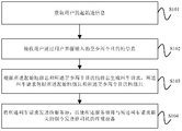
- FIG. 4 is a flowchart of a method for processing a car according to Embodiment 1 of the present application. As shown in FIG. 4, the method may include the following steps:
- Step S101 Acquire initial location information of the user.
- the executor of the embodiment may be a user terminal device, and the user terminal device is installed with a taxi software.
- the taxi software may acquire the location information of the current location of the user, and determine the location information as the location information.
- the starting location information for example, as shown in FIG. 4A
- the taxi software locates the location of the user on the map layer, and displays positioning information such as black dots on the map layer.
- the address information corresponding to the positioning information is displayed in the starting point input box, for example, Facebook Riverside Park, indicating that the user is currently located in the Facebook Riverside Park.
- the user may directly input the starting location information, such as the Facebook Riverside Park, in the start information input box of the user interface, and the initial information input box is specifically shown in FIG. 4A.
- the starting point input box, the taxi software directly obtains the starting location information input by the user in the starting information input box of the user interface.
- the taxi software may also obtain the origin information selected by the user on the map layer of the user interface.
- the taxi software displays a map layer, and the user clicks on the selected location on the map layer, for example, a black point clicked by the finger, and the taxi software places the user on the map layer.
- the selected location is displayed as the user's home location information in the start point input box shown in FIG. 4B.
- Step S102 Receive at least two destination information input by the user through the user interface.
- the user interface includes at least two endpoint input boxes, and the user can input a destination information in each of the endpoint input boxes.
- Step S103 Generate a call request according to the start location information and the at least two destination information, where the call request includes the start location information and the at least two destination information.
- the taxi software generates a call request according to the start location information and the at least two destination information, where the call request includes start location information and at least two destination information.
- Step S104 Send the calling request to the server, so that the server sends an instruction related to the calling request to the terminal device of the driver.
- the driver's terminal device may specifically be a driver's mobile terminal or an in-vehicle device installed in the driver's vehicle.
- the user terminal device sends the call request to the server, and the server generates an instruction related to the call request according to the start location information and the at least two destination information in the call request, and the server may use at least two ways This command is sent to the driver's terminal device.
- the instruction related to the calling request may be order information, and the order information includes the starting location information and the at least two destination information.
- the server may determine, according to the starting location information in the calling request, a terminal device of multiple drivers within a preset distance from the starting location information, and the server sends the order information to the terminal devices of the multiple drivers,
- the plurality of drivers are allowed to grab the order information.
- each driver can obtain the user's origin information and at least two destination information through the respective terminal devices. If the driver is willing to carry the user, the driver terminal device is used. Click Confirm to accept the order information. If multiple drivers grab the order information, the driver who clicks the first confirmation is the driver who receives the order information.
- the order information may further include fee information including multiple travel expenses from the origin to the at least two destinations respectively.
- the instruction related to the calling request may also be a calling instruction; when the server receives the calling request sent by the user terminal device, according to the starting information included in the calling request Determining a plurality of driver terminal devices within a preset distance from the initial location information, and selecting a driver terminal device from the plurality of driver terminal devices by using a scheduling algorithm, and the server sends the calling vehicle receiving command Receiving the terminal device of the selected driver, the terminal device of the driver receives the confirmation instruction of the vehicle, and feeds back confirmation information to the server, and the terminal device of the driver locates the location information of the user according to the initial location information in the request for calling,
- the user may be a passenger or a plurality of passengers in the same class. If it is a passenger, the passenger may take the same vehicle to a different destination in turn, and the passenger may not need to Go to a destination and transfer to a different vehicle.
- the user adds a plurality of destination addresses on the user interface
- the multiple destination addresses include the user's own destination address, and the destination addresses of other users traveling with the user
- the user terminal device starts from the same starting point of multiple users.
- the address and the different destination address generate a calling request, and the calling request is sent to the server, and the server sends the calling request to the driver terminal device around the user terminal device, and if the driver is willing to undertake the order, the Driver terminal equipment response The car request.
- the user and other users can get on the same location from the same location, carrying the same vehicle to different destinations, reducing the number of vehicles on the road and reducing air pollution.
- FIG. 5 is a flowchart of a method for processing a car according to a second embodiment of the present application. As shown in FIG. 5, the method may include the following steps:
- Step S201 Acquire a start location information of the user.
- Step S201 is consistent with step S101, and the specific method is not described herein again.
- the user interface includes at least two destination information input boxes.
- the destination information input box in this embodiment is specifically an end point input box.
- the user interface includes four end point input boxes. In consideration of taxis, express trains, special vehicles, and the like, a maximum of five people can be used, except for the driver. In addition, 4 passengers can be used.
- the user interface in this embodiment displays 4 end input boxes by default.
- Step S202 Receive destination information respectively input by the user in the at least two destination information input boxes, and each destination information input box is used to input one destination information.
- each destination input box can input a destination information, and the user can select at least two end point input boxes in the above four end point input boxes, and input destinations in the at least two end point input boxes respectively.
- Information the destination information is specifically the destination address, and each destination address is different. For example, the user inputs the destination address "Longhu Chunjiang Bianan" in the first end input box, and enters the destination address "Hua in the second end input box”. Ruixiang Lake is beautiful.”
- Step S203 Generate a call request according to the start location information and the at least two destination information, where the call request includes the start location information and the at least two destination information.
- Step S204 Send the calling request to the server, so that the server sends an instruction related to the calling request to the terminal device of the driver.
- Step S203 is the same as step S103, and step S204 is the same as step S104. The specific method is not described here.
- the user interface includes a payment account input box, and each destination information input box corresponds to a payment account input box.
- each destination information input box corresponds to a payment account input box, and the payment account is used to pay from the origin to the destination.
- both A and B are from "Alibaba Riverside Park” takes a taxi to a different destination, A wants to go to "Longhu Chunjiang, the other side", B wants to go to "Huarui Xianghu Meidi", the user who operates the user interface can be A or B, the user enters " After entering the bank of Longhu Chunjiang, enter the payment account of A, enter "Hua Rui Xiang Hu Mei Di” and enter the payment account of B. A and B will take a taxi.
- the user who operates the user interface can input only one payment account, for example, only enter the payment account of A, and do not input the payment account of B, then the travel expenses of both A and B are from the payment account of A. Deducted.
- the user interface of the taxi software includes at least two destination information input boxes, and the user can directly input the destination information in each destination information input box, thereby improving the convenience of the user inputting at least two destination information.
- FIG. 6 is a flowchart of a method for processing a car according to Embodiment 3 of the present application. As shown in FIG. 6, the method may include the following steps:
- Step S301 Acquire initial location information of the user.
- Step S301 is the same as step S101. The specific method is not described here.
- the user interface includes at least one destination information input box and an input box add icon.
- the user interface includes a destination information input box such as an input box of the end point 1, and an input box add icon such as an "add destination" icon, and the input box of the destination 1 is associated with a payment account.
- Step S302 Receive destination information input by the user in the at least one destination information input box.
- the user inputs destination information such as "Longhu Chunjiang Bian" and a payment account in the input box of the destination 1.
- Step S303 Receive an input box adding instruction that is input by the user by clicking the input box to add an icon, and the input box adding instruction is used to add a destination information input box.
- Step S304 adding an instruction according to the input box, and adding a destination information input box to the user interface.
- the taxi software generates an instruction according to the input box generated by the user clicking the "Add Destination" icon to generate a user interface as shown in FIG. 3.
- the user interface shown in FIG. 3 displays the input of the second destination information input box such as the destination 2. Box and payment account input box.
- Step S305 Receive destination information input by the user in the added destination information input box.
- the user inputs the second destination information in the input box of the destination 2, for example, "Hua Rui Xiang Hu Mei Di”.
- Step S306 Generate a call request according to the start location information and the at least two destination information, where the call request includes the start location information and the at least two destination information.
- Step S307 Send the calling request to the server, so that the server sends an instruction related to the calling request to the terminal device of the driver.
- Step S306 is the same as step S103, and step S307 is the same as step S104. The specific method is not described here.
- the number of destination information input boxes that can be added does not exceed the number of passengers that the vehicle can carry.
- the user interface includes at least one destination information input box and an input box add icon.
- the taxi software may add an icon according to the user clicking the input box.
- the input box adds an instruction, and a new destination information input box is added in the user interface, and the user can determine the number of times the icon is added by clicking the input box according to the number of destination information that needs to be input, thereby improving the user inputting at least two destination information. Flexibility.
- FIG. 7 is a flowchart of a method for processing a car according to Embodiment 4 of the present application. As shown in FIG. 7, the method may include the following steps:
- Step S401 Acquire a start location information of the user.
- Step S401 is the same as step S101, and the specific method is not described again.
- the user interface includes a map layer.
- Step S402 Receive at least two destination information selected by the user on a map layer.
- the user sequentially selects two destination information on the map layer, for example, first selects the end point 1 and then selects the end point 2, the taxi software recognizes the address information of the end point 1 clicked by the user, and the user clicks.
- the address information of the end point 2 and the address information of the end point 1 is displayed in the input box of the first destination information input box, that is, the end point 1, and the address information of the end point 2 is displayed in the second destination information input box, that is, the end point. 2 input box.
- Step S403 generating a call request according to the start location information and the at least two destination information, where the call request includes the start location information and the at least two destination information.
- Step S404 Send the call request to the server, so that the server sends an instruction related to the call request to the terminal device of the driver.
- Step S403 is the same as step S103, and step S404 is the same as step S104. The specific method is not described here.
- the user can sequentially select at least two destination information on the map layer, which further improves the flexibility of the user to input at least two destination information.
- FIG. 8 is a flowchart of a method for processing a car according to a fifth embodiment of the present application.
- the embodiment may be based on the embodiment shown in FIG. 4, FIG. 5, and FIG. 6, as shown in FIG. Based on the embodiment shown in FIG. 4, the method may include the following steps:
- Step S501 Obtain the start location information of the user.
- Step S501 is the same as step S101, and the specific method is not described herein again.
- Step S502 Receive at least two destination information input by the user through the user interface.
- the method for the user to input the at least two destination information through the user interface is consistent with the method shown in FIG. 2 and FIG. 3 , and the specific method is not described herein again.
- Step S503 marking the at least two destination information on a map layer.
- Step S504 displaying path information from the origin to the at least two destinations on the map layer.
- the taxi software marks the start point and the end point 1 on the map layer, as shown in the map layer shown in FIG.
- the taxi software can also mark the path information from the start point to the end point 1 on the map layer.
- the taxi software can also budget the travel cost from the start point to the end point 1. For example, the travel cost from the start point to the end point 1 is 40 yuan, and the taxi software displays "40 yuan" around "end point 1" for the user's reference.
- a user interface as shown in FIG. 3 is generated.
- the destination 2 is marked on the map layer.
- the taxi software can also mark the path information from the start point to the end point 2 on the map layer.
- the taxi software can also budget the travel cost from the start point to the end point 2. For example, the travel cost from the start point to the end point 2 is 20 yuan, and the taxi software displays "20 yuan" around "end point 2" for the user's reference.
- a user interface as shown in FIG. 8A is generated.
- the taxi software When the user clicks the "start taxi” icon shown in FIG. 8A, the taxi software generates a call request according to the start point, the end point 1 and the end point 2, and the call request includes the address information corresponding to the start point, the end point 1 and the end point 2 respectively.
- the driver terminal device If the driver is willing to accept the order, the driver terminal device responds to the request for the car. Since the end point 1 is arranged in front of the end point 2, the driver will send the passenger D to the end point 1 according to the order of the end point 1 and the end point 2. Passengers are sent to the end point 2.
- Step S505 Generate a call request according to the start location information and the at least two destination information, where the call request includes the start location information and the at least two destination information.
- Step S506 Send the call request to the server, so that the server sends an instruction related to the call request to the terminal device of the driver.
- Step S505 is the same as step S103, and step S506 is the same as step S104. The specific method is not described here.
- the taxi software marks the start and end points input by the user on the map layer, and displays the path information from the starting point to each end point on the map layer, and the travel cost from the starting point to each end point, so that the user intuitively
- step S504 is a flowchart of a method for processing a car according to a sixth embodiment of the present application. As shown in FIG. 9, on the basis of the embodiment shown in FIG. 8, after step S504, the method further includes the following steps:
- Step S601 Receive a destination sorting instruction input by the user on the user interface, where the destination sorting instruction includes sorting information of the at least two destination information.
- the method for receiving the destination ordering instruction input by the user on the user interface may be specifically implemented by: receiving a destination sorting instruction input by the user on the user interface by adjusting an arrangement order of each destination information input box. .
- the user can further adjust the order of the end point 1 and the end point 2, as shown in FIG. 9A, the user can click the input box of the second destination information input box, that is, the end point 2 for a long time, so that the first The two destination information input boxes are in a floating state.
- the second destination information input box is moved to the top of the first destination information input box, and the generated image is generated.
- User interface shown in 9B User interface shown in 9B.
- Step S602 Set an identification number corresponding to each destination information in the map layer according to the destination sorting instruction.
- the positioning identifier on the map layer is further adjusted according to the adjusted order of the end point 1 and the end point 2.
- the end point 1 is "the other side of Longhu Chunjiang” and the end point 2 is "Huarui Xianghu Meidi", indicating that passenger Ding first got off at "Longhu Chunjiang Bian'an” and passenger C was in "Huarui Xianghu” Get off at the US. From the map layer shown in FIG.
- the end point 1 is farther from the starting point than the end point 2, and according to the current order of the end point 1 and the end point 2, the driver needs to send the passenger to the end point 1 of the map layer display. After the passenger C is sent to the end point 2 of the map layer display, the driver's driving path is increased, causing inconvenience to the driver.
- the user can adjust the arrangement order of each end point according to the distance from the starting point of each end point displayed on the map layer. For example, according to the method shown in FIG. 9A, after adjusting the arrangement order of the end point 1 and the end point 2, in FIG.
- the end point 1 is "Hua Rui Xiang Hu Mei Di”
- the end point 2 is "Long Hu Chun Jiang Bi An”
- passenger C first got off at the end point 1 "Hua Rui Xiang Hu Mei Di”
- passenger Ding Hou at the end point 2 "Longhu Chunjiang "Get off the bus, correspondingly, adjust the positioning logo on the map layer "Hua Rui Xiang Hu Mei Di” and “Long Hu Chun Jiang Bi An”
- Point 1 identifies “Hua Rui Xiang Hu Mei Di”
- End Point 2 identifies “Long Hu Chun Jiang Bi An”.
- the driver needs to send the passenger C to the end point 1 of the map layer display, and then send the passenger to the end point 2 of the map layer display.
- the calling request further includes ranking information of the at least two destination information.
- the calling request includes the end point 1 and the end point 2, and also includes the sorting information of the end point 1 and the end point 2.
- the taxi software When the user clicks the "start taxi” icon shown in FIG. 9B, the taxi software generates a request for the car according to the start point, the end point 1 and the end point 2. If the driver is willing to accept the order, the driver terminal device responds to the call request.
- the call request includes the end point 1 and the end point 2, and also includes the sorting information of the end point 1 and the end point 2.
- the driver will send the passenger C to the end point 1 according to the order of the end point 1 and the end point 2, and then send the passenger to the destination 1 End point 2.
- the taxi software or the server can deduct the first pen from the starting point to the ending point 1 from the payment account of the passenger C.
- the cost of the trip the first trip fee may be less than or equal to the travel fee from the start to the end point 1 in the prior art.
- the taxi software or the server can deduct the second travel fee from the origin to the destination 2 from the passenger's payment account, and the second travel fee can be less than or equal to the prior art. The cost of the trip from the beginning to the end point 2.
- the order of at least two destination information is adjusted by the user dragging the destination information input box in the user interface, and the order of the order indicates the order in which the at least two passengers arrive at the respective destinations, and the user can pass the
- the user interface adjusts the order in which passengers get off at any time, further enhancing the user experience.
- a car handling device in accordance with one or more embodiments of the present application will be described in detail below. These car handling devices can be implemented in the terminal device. Those skilled in the art will appreciate that these vehicle handling devices can be constructed using commercially available hardware components configured by the steps taught by the present solution.
- the processor component or processing module, processing unit
- these vehicle handling devices can be constructed using commercially available hardware components configured by the steps taught by the present solution.
- the processor component or processing module, processing unit
- the processor component can use components such as a microcontroller, a microcontroller, a microprocessor, etc. from Texas Instruments, Intel Corporation, ARM, and the like.
- FIG. 10 is a schematic structural diagram of a vehicle handling device according to Embodiment 1 of the present application, as shown in FIG.
- the device includes: an obtaining module 11, a receiving module 12, a generating module 13, and a sending module 14.
- the obtaining module 11 is configured to acquire the starting location information of the user.
- the receiving module 12 is configured to receive at least two destination information input by the user through the user interface.
- the generating module 13 is configured to generate a calling request according to the starting location information and the at least two destination information, where the calling request includes the starting location information and the at least two destination information.
- the sending module 14 is configured to send the calling request to the server, so that the server sends an instruction related to the calling request to the terminal device of the driver.
- the device shown in FIG. 10 can perform the car handling method described in the embodiment shown in FIG. 4, and the implementation principle and technical effects thereof are not described again.
- the acquiring module 11 is specifically configured to acquire positioning information of a user location. Determining the location information as the origin information; or acquiring the origin information input by the user in the start information input box of the user interface; or acquiring the user in the user interface The starting location information selected on the map layer.
- the user interface includes at least two destination information input boxes, and the receiving module 12 is specifically configured to receive destination information input by the user in the at least two destination information input boxes, each destination.
- the information input box is used to enter a destination information.
- the user interface includes at least one destination information input box and an input box add icon;
- the receiving module 12 includes: a receiving unit 121 and an input box adding unit 122.
- the receiving unit 121 is configured to receive destination information input by the user in the at least one destination information input box, and receive an input box adding instruction that the user inputs an icon input by clicking the input box, the input box
- the add instruction is used to add a destination information input box.
- the input box adding unit 122 is configured to add a destination information input box to the user interface according to the input box adding instruction.
- the receiving unit 121 is further configured to receive destination information input by the user in the added destination information input box.
- the device shown in FIG. 11 can perform the car handling method described in the embodiment shown in FIG. 5 and FIG. 6, and the implementation principle and technical effects are not described again.
- FIG. 12 is a schematic structural diagram of a vehicle handling device according to Embodiment 3 of the present application. As shown in FIG. 12, on the basis of the embodiment shown in FIG. 11, the device further includes: a marking module 15.
- the marking module 15 is configured to mark the at least two destination information on a map layer; display path information from the origin to the at least two destinations on the map layer.
- the receiving module 12 is further configured to receive a destination sorting instruction input by the user on the user interface, where the destination sorting instruction includes sorting information of the at least two destination information.
- the marking module 15 is further configured to set an identification number corresponding to each destination information in the map layer according to the destination sorting instruction.
- the device shown in FIG. 12 can perform the car handling method described in the embodiments shown in FIG. 8 and FIG. 9 , and the implementation principle and technical effects thereof are not described again.
- the car handling device can be implemented as a terminal device, including: a processor, a display, a receiver, and a transmitter.
- the display is coupled to the processor for displaying a user interface.
- the receiver is coupled to the processor for receiving at least two destination information input by a user through a user interface.
- the processor is configured to acquire start information of the user, generate a call request according to the start location information and the at least two destination information, where the call request includes the start location information and the location Describe at least two destination information.
- the transmitter is coupled to the processor for transmitting the call request to a server, so that the server sends an instruction related to the call request to a driver's terminal device.
- the user adds a plurality of destination addresses on the user interface
- the multiple destination addresses include the user's own destination address, and the destination addresses of other users traveling with the user
- the user terminal device starts from the same starting point of multiple users.
- the address and the different destination address generate a calling request, and the calling request is sent to the server, and the server sends the calling request to the driver terminal device around the user terminal device, and if the driver is willing to undertake the order, the Driver terminal equipment response The car request.
- the user and other users can get on the same location from the same location, carrying the same vehicle to different destinations, reducing the number of vehicles on the road and reducing air pollution.
- FIG. 14 is a schematic diagram of a user interface system according to an embodiment of the present disclosure.
- the user interface system includes: a display component 1, a processor 2, and a transmitter 3.
- Display component 1 for displaying the user interface.
- the processor 2 is configured to trigger display of the display component by the display component, generate a call request according to the start location information input by the user on the user interface, and the at least two destination information, where the call request includes The origin information and the at least two destination information.
- the transmitter 3 is configured to send the calling request to the server, so that the server sends an instruction related to the calling request to the terminal device of the driver.
- the user interface includes at least two destination information input boxes; each destination information input box is used to input one destination information.
- the user interface includes at least one destination information input box and an input box add icon; the at least one destination information input box is used to input at least one destination information; the input box adds an icon Used to add a destination information input box to the user interface.
- the user can refer to the description in the foregoing method embodiment.
- the user interface includes a payment account input box, and each destination information input box corresponds to a payment account input box.
- the user interface includes a map layer.
- the processor is further configured to trigger the display component to mark the at least two destination information on the map layer, and trigger the display component to be on the map
- the path information from the origin to the at least two destinations is displayed on the layer.
- the processor is further configured to trigger the display component to adjust a layout of each destination information input box in the user interface based on the operation of the user on each destination information input box. For example, in the method embodiment IX, on the basis of FIG. 8A, the user can further adjust the order of the end point 1 and the end point 2, as shown in FIG. 9A, the user can click the second destination information input box for a long time.
Landscapes
- Engineering & Computer Science (AREA)
- Multimedia (AREA)
- Computer Networks & Wireless Communication (AREA)
- Signal Processing (AREA)
- Traffic Control Systems (AREA)
- Navigation (AREA)
Abstract
本申请提供一种叫车处理方法、装置、设备和系统。该方法包括:获取用户的起始地信息;接收用户通过用户界面输入的至少两个目的地信息;根据所述起始地信息和所述至少两个目的地信息生成叫车请求,所述叫车请求包括所述起始地信息和所述至少两个目的地信息;将所述叫车请求发送给服务器,以使所述服务器将与所述叫车请求相关的指令发送给司机的终端设备。用户和其他用户可从同一地点上车,承载同一辆车分别去往不同的目的地,减少了路上行驶车辆的数量,同时减轻了空气污染。
Description
本申请涉及互联网技术,尤其涉及一种叫车处理方法、装置、设备和系统。
随着互联网技术的发展,使用打车软件打车已经成为人们日常出行方式的一种。
现有技术中,用户终端设备安装有打车软件,用户在该打车软件提供的用户界面输入自己的出发地点和目的地点,点击确认图标后,用户终端设备将包括用户出发地点和目的地点的叫车请求上传给服务器,服务器将该叫车请求发送给用户终端设备周围的司机终端设备,该用户可等待响应该叫车请求的司机前来接送。
但是,当用户需要和自己的朋友、家人或同事一同出行时,若该用户和自己同行的朋友、家人或同事的目的地点不同,则用户和自己同行的朋友、家人或同事需要分别打各自的车,造成路上行驶车辆的数量增多,加重了空气污染。
发明内容
本申请提供一种叫车处理方法、装置、设备和系统,以减少路上行驶车辆的数量,同时减轻空气污染。
一个方面,本申请提供一种叫车处理方法,该方法包括:
获取用户的起始地信息;
接收用户通过用户界面输入的至少两个目的地信息;
根据所述起始地信息和所述至少两个目的地信息生成叫车请求,所述叫车请求包括所述起始地信息和所述至少两个目的地信息;
将所述叫车请求发送给服务器,以使所述服务器将与所述叫车请求相关
的指令发送给司机的终端设备。
另一方面,本申请提供一种叫车处理装置,包括:
获取模块,用于获取用户的起始地信息;
接收模块,用于接收用户通过用户界面输入的至少两个目的地信息;
生成模块,用于根据所述起始地信息和所述至少两个目的地信息生成叫车请求,所述叫车请求包括所述起始地信息和所述至少两个目的地信息;
发送模块,用于将所述叫车请求发送给服务器,以使所述服务器将与所述叫车请求相关的指令发送给司机的终端设备。
再一方面,本申请提供一种终端设备,包括:处理器、显示器、接收器、发送器;
所述显示器,耦合到所述处理器,用于显示用户界面;
所述接收器,耦合到所述处理器,用于接收用户通过用户界面输入的至少两个目的地信息;
所述处理器,用于获取用户的起始地信息;根据所述起始地信息和所述至少两个目的地信息生成叫车请求,所述叫车请求包括所述起始地信息和所述至少两个目的地信息;
所述发送器,耦合到所述处理器,用于将所述叫车请求发送给服务器,以使所述服务器将与所述叫车请求相关的指令发送给司机的终端设备。
还一方面,本申请提供一种用户界面系统,包括:
显示组件,用于显示用户界面;
处理器,用于触发所述显示组件对所述用户界面的显示,根据用户在所述用户界面输入的起始地信息和至少两个目的地信息生成叫车请求,所述叫车请求包括所述起始地信息和所述至少两个目的地信息;
发送器,用于将所述叫车请求发送给服务器,以使所述服务器将与所述叫车请求相关的指令发送给司机的终端设备。
在本申请中,通过用户在用户界面上添加多个终点地址,该多个终点地址包括用户自己的终点地址,以及与自己同行的其他用户的终点地址,用户终端设备根据多个用户相同的起点地址和不同的终点地址生成叫车请求,并将该叫车请求发送给服务器,服务器将该叫车请求发送给该用户终端设备周围的司机终端设备,若有司机愿意承接该笔订单,则通过司机终端设备响应
该叫车请求。该用户和其他用户可从同一地点上车,承载同一辆车分别去往不同的目的地,减少了路上行驶车辆的数量,同时减轻了空气污染。
为了更清楚地说明本发明实施例或现有技术中的技术方案,下面将对实施例或现有技术描述中所需要使用的附图作一简单地介绍,显而易见地,下面描述中的附图是本发明的一些实施例,对于本领域普通技术人员来讲,在不付出创造性劳动性的前提下,还可以根据这些附图获得其他的附图。
图1为现有技术中打车软件用户界面的示意图;
图2为本申请的一种可选的打车软件用户界面的示意图;
图3为本申请的另一种可选的打车软件用户界面的示意图;
图4为本申请实施例一提供的叫车处理方法的流程图;
图4A为执行图4所示实施例过程中的用户界面状态示意图;
图4B为执行图4所示实施例过程中的用户界面状态示意图;
图5为本申请实施例二提供的叫车处理方法的流程图;
图5A为执行图5所示实施例过程中的用户界面状态示意图;
图5B为执行图5所示实施例过程中的用户界面状态示意图;
图6为本申请实施例三提供的叫车处理方法的流程图;
图7为本申请实施例四提供的叫车处理方法的流程图;
图7A为执行图7所示实施例过程中的用户界面状态示意图;
图8为本申请实施例五提供的叫车处理方法的流程图;
图8A为执行图8所示实施例过程中的用户界面状态示意图;
图9为本申请实施例六提供的叫车处理方法的流程图;
图9A为执行图9所示实施例过程中的用户界面状态示意图;
图9B为执行图9所示实施例过程中的用户界面状态示意图;
图10为本申请实施例一提供的叫车处理装置的结构示意图;
图11为本申请实施例二提供的叫车处理装置的结构示意图;
图12为本申请实施例三提供的叫车处理装置的结构示意图;
图13本申请实施例提供的终端设备的结构示意图;
图14为本申请一实施例提供的用户界面系统的示意图。
这里将详细地对示例性实施例进行说明,其示例表示在附图中。下面的描述涉及附图时,除非另有表示,不同附图中的相同数字表示相同或相似的要素。以下示例性实施例中所描述的实施方式并不代表与本发明相一致的所有实施方式。相反,它们仅是与如所附权利要求书中所详述的、本发明的一些方面相一致的装置和方法的例子。
现有技术中,用户终端设备可安装有打车软件,该打车软件的用户界面可如图1所示,如图1所示,该用户界面显示有地图图层。用户通过图1所示的用户界面输入自己的起点地址例如阿里巴巴滨江园区,或者,用户在图1所示的用户界面点击用车,打车软件自动获取用户终端设备当前的定位信息,并将用户终端设备当前的定位信息作为用户的起点地址。另外,用户还可通过图1所示的用户界面输入自己的终点地址、以及支付账号,该打车软件根据起点地址和终点地址,可规划多条路径以供用户参考,该支付账号用于支付从起点地址到终点地址的行程费用。用户确认打车后,用户终端设备根据用户输入的起点地址和终点地址生成叫车请求,并将该叫车请求发送给服务器,服务器将该叫车请求发送给用户终端设备周围的司机终端设备,若司机愿意承载该用户,则通过司机终端设备点击确认,响应该叫车请求。当用户到达终点地址后,打车软件将产生的行程费用从用户输入的支付账号中进行扣除。在本实施例中,司机可以是出租车司机、快车司机、专车司机、代驾司机或顺风车司机。
但是,当用户需要和自己的朋友、家人或同事一同出行时,若该用户和自己同行的朋友、家人或同事的目的地点不同,则用户和自己同行的朋友、家人或同事需要分别打各自的车,到达各自想去的终点地址,从而造成行驶车辆的数量增多,加重了空气污染。为了解决该问题,本案提供了一种叫车处理方法,下面结合图2和图3具体介绍该叫车处理方法。
如图2所示,用户界面还包括“添加目的地”图标,用户点击“添加目的地”图标后,生成图3所示的用户界面,在图1的基础上,用户还可以在图3所示的用户界面添加第2个终点地址,同理,用户添加第2个终点地址
后,还可通过点击“添加目的地”图标添加第3个终点地址,即通过点击“添加目的地”图标可添加多个终点地址,但添加的终点地址的总个数不可超过车辆的允许载客数量。另外,用户每添加一个终点地址,对应输入一个支付账号,该支付账号可以是支付宝账号、银行账号或支付宝好友的支付宝账号,每个终点地址关联的支付账号用于支付从起点地址到该终点地址的行程费用,即乘坐同一辆车的乘客可单独结算行程费用。
可选的,用户与同事A、同事B一同打车回家,用户、同事A、同事B的起点地址相同,均是公司地址,用户、同事A、同事B的终点地址互不相同,则用户可通过上述方法依次输入自己的终点地址和支付账号、同事A的终点地址和支付账号、以及同事B的终点地址和支付账号。用户终端设备根据用户、同事A、同事B相同的起点地址,以及用户、同事A、同事B不同的终点地址生成叫车请求,若有司机愿意承接该笔订单,则通过司机终端设备响应该叫车请求。用户、同事A、同事B乘车后,该司机将按照用户、同事A、同事B的终点地址的顺序将用户、同事A、同事B依次送到终点地址,用户、同事A、同事B各自产生的行程费用可分别从各自的支付账号中扣除。
另外,在其他实施例中,用户、同事A、同事B的行程路径还可以有部分重叠,即用户、同事A、同事B可以顺路回家。
此外,在其他实施例中,该多个乘车用户可以从同一地点上车,去往不同的终点,从起点到各个终点的路程可以互不重叠,即乘坐同一辆车的多个用户还可以不顺路。
本实施例中,通过用户在用户界面上添加多个终点地址,该多个终点地址包括用户自己的终点地址,以及与自己同行的其他用户的终点地址,用户终端设备根据多个用户相同的起点地址和不同的终点地址生成叫车请求,并将该叫车请求发送给服务器,服务器将该叫车请求发送给该用户终端设备周围的司机终端设备,若有司机愿意承接该笔订单,则通过司机终端设备响应该叫车请求。多个用户乘车后,该司机将按照多个终点地址的顺序将该多个用户依次送到终点地址,即该用户和其他用户可从同一地点上车,承载同一辆车分别去往不同的目的地,减少了路上行驶车辆的数量,同时减轻了空气污染。
图4为本申请实施例一提供的叫车处理方法的流程图,如图4所示,该方法可以包括如下步骤:
步骤S101、获取用户的起始地信息。
本实施例的执行主体可以是用户终端设备,该用户终端设备安装有打车软件,当用户开启该打车软件时,该打车软件可获取用户当前所在地点的定位信息,将所述定位信息确定为所述起始地信息,例如图4A所示,当用户开启该打车软件后,该打车软件在地图图层上对用户所在的位置进行定位,并在地图图层上显示定位信息例如黑色圆点,并将该定位信息对应的地址信息显示在起点输入框中,例如阿里巴巴滨江园区,表示用户当前位于阿里巴巴滨江园区。
另外,在其他实施例中,用户还可以直接在所述用户界面的起始地信息输入框中输入起始地信息,例如阿里巴巴滨江园区,该起始地信息输入框具体为图4A所示的起点输入框,该打车软件直接获取用户在所述用户界面的起始地信息输入框中输入的起始地信息。
此外,在其他实施例中,打车软件还可以获取所述用户在所述用户界面的地图图层上选定的起始地信息。如图4B所示,用户开启该打车软件后,该打车软件显示有地图图层,用户在地图图层上点击选定地点,例如手指点击的黑点,该打车软件将用户在地图图层上选定的地点作为用户的起始地信息显示在图4B所示的起点输入框。
步骤S102、接收用户通过用户界面输入的至少两个目的地信息。
另外,如图4A和图4B所示,用户界面至少包括两个终点输入框,用户可在每个终点输入框中输入一个目的地信息。
步骤S103、根据所述起始地信息和所述至少两个目的地信息生成叫车请求,所述叫车请求包括所述起始地信息和所述至少两个目的地信息。
可选的,该打车软件根据上述起始地信息和至少两个目的地信息生成叫车请求,该叫车请求中包括起始地信息和至少两个目的地信息。
步骤S104、将所述叫车请求发送给服务器,以使所述服务器将与所述叫车请求相关的指令发送给司机的终端设备。
在本实施例中,司机的终端设备具体可以是司机的移动终端或设置于司机车辆的车载设备。用户终端设备将该叫车请求发送给服务器,服务器根据该叫车请求中的起始地信息和至少两个目的地信息生成与该叫车请求相关的指令,服务器可通过以下至少两种方式将该指令发送给司机的终端设备。在第一种方式中,与该叫车请求相关的指令可以是订单信息,该订单信息包括该起始地信息和该至少两个目的地信息。服务器可根据该叫车请求中的起始地信息,确定出距离该起始地信息在预设距离内的多个司机的终端设备,服务器将该订单信息发送给多个司机的终端设备,以使多个司机抢接该订单信息,具体的,每个司机可通过各自的终端设备获知用户的起始地信息和至少两个目的地信息,若该司机愿意承载该用户,则通过司机终端设备点击确认以承接该订单信息,若多个司机抢接该订单信息,则以最先点击确认的司机为承接该订单信息的司机。此外,该订单信息中还可以包括费用信息,该费用信息包括从起始地分别到至少两个目的地的多笔行程费用。
在第二种方式中,与该叫车请求相关的指令还可以是叫车承接指令;当服务器接收到用户终端设备发送的叫车请求后,可根据该叫车请求中包括的起始地信息,确定出距离该起始地信息在预设距离内的多个司机的终端设备,并通过调度算法从多个司机的终端设备中选取一个司机的终端设备,并且服务器将该叫车承接指令发送给选取出的司机的终端设备,该司机的终端设备接收该叫车承接指令后,向服务器反馈确认信息,该司机的终端设备根据叫车请求中的起始地信息定位用户所在的位置信息,以便承载该用户,该用户可以是一名乘客,也可以是同行的多名乘客,若是一名乘客,则该名乘客可乘同一辆车依次去往不同的目的地,该名乘客可无需每去往一个目的地换乘不同的车辆。
本实施例中,通过用户在用户界面上添加多个终点地址,该多个终点地址包括用户自己的终点地址,以及与自己同行的其他用户的终点地址,用户终端设备根据多个用户相同的起点地址和不同的终点地址生成叫车请求,并将该叫车请求发送给服务器,服务器将该叫车请求发送给该用户终端设备周围的司机终端设备,若有司机愿意承接该笔订单,则通过司机终端设备响应
该叫车请求。该用户和其他用户可从同一地点上车,承载同一辆车分别去往不同的目的地,减少了路上行驶车辆的数量,同时减轻了空气污染。
图5为本申请实施例二提供的叫车处理方法的流程图,如图5所示,该方法可以包括如下步骤:
步骤S201、获取用户的起始地信息。
步骤S201与步骤S101一致,具体方法此处不再赘述。
在本实施例中,所述用户界面包括至少两个目的地信息输入框。本实施例中的目的地信息输入框具体为终点输入框,如图5A所示,用户界面包括4个终点输入框,考虑到出租车、快车、专车等交通工具最多可乘坐5人,除了司机之外,可乘坐4名乘客,可选的,本实施例中的用户界面默认显示4个终点输入框。
步骤S202、接收所述用户在所述至少两个目的地信息输入框中分别输入的目的地信息,每个目的地信息输入框用于输入一个目的地信息。
如图5A所示,每个终点输入框可输入一个目的地信息,用户可在上述4个终点输入框中选择至少两个终点输入框,并在该至少两个终点输入框中分别输入目的地信息,该目的地信息具体为终点地址,且各个终点地址不同,例如,用户在第一个终点输入框中输入终点地址“龙湖春江彼岸”,在第二个终点输入框中输入终点地址“华瑞湘湖美地”。
步骤S203、根据所述起始地信息和所述至少两个目的地信息生成叫车请求,所述叫车请求包括所述起始地信息和所述至少两个目的地信息。
步骤S204、将所述叫车请求发送给服务器,以使所述服务器将与所述叫车请求相关的指令发送给司机的终端设备。
步骤S203与步骤S103一致,步骤S204和步骤S104一致,具体方法此处不再赘述。
另外,所述用户界面包括支付账号输入框,每个目的地信息输入框对应一个支付账号输入框。如图5B所示,用户在输入每个目的地信息时,还需要输入支付账号,每个目的地信息输入框对应一个支付账号输入框,该支付账号用于支付从起始地到目的地的行程费用,例如,甲和乙同时从
“阿里巴巴滨江园区”打车到不同的目的地,甲要去“龙湖春江彼岸”,乙要去“华瑞湘湖美地”,操作该用户界面的用户可以是甲或乙,该用户输入“龙湖春江彼岸”后输入甲的支付账号,输入“华瑞湘湖美地”后输入乙的支付账号,甲和乙同乘一辆出租车,甲到达“龙湖春江彼岸”后,从甲的支付账号中扣除从“阿里巴巴滨江园区”到“龙湖春江彼岸”的行程费用;乙到达“华瑞湘湖美地”后,从乙的支付账号中扣除从“阿里巴巴滨江园区”到“华瑞湘湖美地”的行程费用。
此外,在其他实施例中,操作该用户界面的用户可以只输入一个支付账号,例如,只输入甲的支付账号,不输入乙的支付账号,则甲和乙的行程费用都从甲的支付账号中扣除。
本实施例中,打车软件的用户界面包括至少两个目的地信息输入框,用户可在每个目的地信息输入框中直接输入目的地信息,提高了用户输入至少两个目的地信息的便捷性。
图6为本申请实施例三提供的叫车处理方法的流程图,如图6所示,该方法可以包括如下步骤:
步骤S301、获取用户的起始地信息。
步骤S301与步骤S101一致,具体方法此处不再赘述。
在本实施例中,所述用户界面包括至少一个目的地信息输入框和输入框添加图标。如图2所示,用户界面包括一个目的地信息输入框例如终点1的输入框,以及一个输入框添加图标例如“添加目的地”图标,并且终点1的输入框关联有一个支付账号。
步骤S302、接收所述用户在所述至少一个目的地信息输入框中输入的目的地信息。
如图2所示,用户在终点1的输入框中输入目的地信息例如“龙湖春江彼岸”以及支付账号。
步骤S303、接收所述用户通过点击所述输入框添加图标输入的输入框添加指令,所述输入框添加指令用于添加目的地信息输入框。
当用户还需添加第二个目的地信息时,点击如图2所示的“添加目的
地”图标,用户点击“添加目的地”图标时,打车软件生成输入框添加指令,该输入框添加指令用于在如图2所示的用户界面上添加另一个目的地信息输入框。
步骤S304、根据所述输入框添加指令,在所述用户界面增加目的地信息输入框。
打车软件根据用户点击“添加目的地”图标生成的输入框添加指令,生成如图3所示的用户界面,如图3所示的用户界面显示第二个目的地信息输入框例如终点2的输入框和支付账号输入框。
步骤S305、接收所述用户在增加的目的地信息输入框中输入的目的地信息。
如图3所示,用户在终点2的输入框中输入第二个目的地信息,例如“华瑞湘湖美地”。
步骤S306、根据所述起始地信息和所述至少两个目的地信息生成叫车请求,所述叫车请求包括所述起始地信息和所述至少两个目的地信息。
步骤S307、将所述叫车请求发送给服务器,以使所述服务器将与所述叫车请求相关的指令发送给司机的终端设备。
步骤S306和步骤S103一致,步骤S307和步骤S104一致,具体方法此处不再赘述。
另外,可添加的目的地信息输入框的个数不超过车辆可承载的乘客数量。
本实施例中,用户界面包括至少一个目的地信息输入框和输入框添加图标,当用户需要增加目的地信息的个数时,点击输入框添加图标,打车软件可根据用户点击输入框添加图标产生的输入框添加指令,在用户界面添加新的目的地信息输入框,用户可根据需要输入的目的地信息的个数,确定点击输入框添加图标的次数,提高了用户输入至少两个目的地信息的灵活性。
图7为本申请实施例四提供的叫车处理方法的流程图,如图7所示,该方法可以包括如下步骤:
步骤S401、获取用户的起始地信息。
步骤S401与步骤S101一致,具体方法不再赘述。
所述用户界面包括地图图层。
步骤S402、接收所述用户在地图图层上选定的至少两个目的地信息。
如图7A所示,用户在地图图层上顺序选定两个目的地信息,例如先选定终点1,后选定终点2,打车软件识别出用户点击的终点1的地址信息,以及用户点击的终点2的地址信息,并将终点1的地址信息显示在第一个目的地信息输入框即终点1的输入框,以及将终点2的地址信息显示在第二个目的地信息输入框即终点2的输入框。
步骤S403、根据所述起始地信息和所述至少两个目的地信息生成叫车请求,所述叫车请求包括所述起始地信息和所述至少两个目的地信息。
步骤S404、将所述叫车请求发送给服务器,以使所述服务器将与所述叫车请求相关的指令发送给司机的终端设备。
步骤S403与步骤S103一致,步骤S404与步骤S104一致,具体方法此处不再赘述。
本实施例中,用户可在地图图层上顺序选定至少两个目的地信息,进一步提高了用户输入至少两个目的地信息的灵活性。
图8为本申请实施例五提供的叫车处理方法的流程图,本实施例可以以图4、图5、图6所示实施例为基础,如图8所示,可选的,以图4所示实施例为基础,该方法可以包括如下步骤:
步骤S501、获取用户的起始地信息。
步骤S501与步骤S101一致,具体方法此处不再赘述。
步骤S502、接收用户通过用户界面输入的至少两个目的地信息。
可选的,在本实施例中,用户通过用户界面输入至少两个目的地信息的方法与图2、图3所示的方法一致,具体方法此处不再赘述。
步骤S503、将所述至少两个目的地信息标记在地图图层上。
步骤S504、在所述地图图层上显示从起始地到至少两个目的地的路径信息。
如图2所示,当用户输入第一个目的地信息后,打车软件将起点和终点1标记在地图图层上,如图2所示的地图图层上显示的起点和终点1。另外,打车软件还可在该地图图层上标记出从起点到终点1的路径信息。此外,打车软件还可预算出从起点到终点1的行程费用,例如,从起点到终点1的行程费用是40元,打车软件将“40元”显示在“终点1”周围,以便用户参考。
当用户点击“添加目的地”图标后,生成如图3所示的用户界面,用户输入第二个目的地信息后,将终点2标记在地图图层上。另外,打车软件还可在该地图图层上标记出从起点到终点2的路径信息。此外,打车软件还可预算出从起点到终点2的行程费用,例如,从起点到终点2的行程费用是20元,打车软件将“20元”显示在“终点2”周围,以便用户参考。
在图3的基础上,用户输入第二个终点信息“华瑞湘湖美地”,以及第二个支付账号后,生成如图8A所示的用户界面。当用户点击图8A所示的“开始打车”图标后,打车软件根据起点、终点1和终点2生成叫车请求,该叫车请求中包括起点、终点1和终点2分别对应的地址信息,若有司机愿意承接该笔订单,则通过司机终端设备响应该叫车请求,由于终点1排列在终点2的前面,司机将按照终点1和终点2的排列顺序,将乘客丁先送到终点1,将乘客丙后送到终点2。
步骤S505、根据所述起始地信息和所述至少两个目的地信息生成叫车请求,所述叫车请求包括所述起始地信息和所述至少两个目的地信息。
步骤S506、将所述叫车请求发送给服务器,以使所述服务器将与所述叫车请求相关的指令发送给司机的终端设备。
步骤S505与步骤S103一致,步骤S506与步骤S104一致,具体方法此处不再赘述。
本实施例中,打车软件将用户输入的起点和终点标记在地图图层上,并在地图图层上显示从起点到各个终点的路径信息,以及从起点到各个终点的行程费用,使用户直观的看到从起点到各个终点的路径信息,以及行程费用,提高了用户体验。
图9为本申请实施例六提供的叫车处理方法的流程图,如图9所示,在图8所示实施例的基础上,步骤S504之后,该方法还包括如下步骤:
步骤S601、接收所述用户在所述用户界面上输入的目的地排序指令,所述目的地排序指令包括所述至少两个目的地信息的排序信息。
接收所述用户在所述用户界面上输入的目的地排序指令的方法具体可实现为:接收所述用户在所述用户界面上通过调整各目的地信息输入框的排列顺序输入的目的地排序指令。
在图8A的基础上,用户还可进一步调整终点1和终点2的排列顺序,如图9A所示,用户可长时间点击第二个目的地信息输入框即终点2的输入框,以使第二个目的地信息输入框处于悬浮状态,当第二个目的地信息输入框处于悬浮状态后,将第二个目的地信息输入框移动到第一个目的地信息输入框的上面,生成如图9B所示的用户界面。
步骤S602、根据所述目的地排序指令,设置所述地图图层中各目的地信息对应的标识号。
如图9B所示,用户调整终点1和终点2的排列顺序后,根据调整后的终点1和终点2的排列顺序,进一步调整地图图层上的定位标识。例如,在图9A中,终点1是“龙湖春江彼岸”,终点2是“华瑞湘湖美地”,表示乘客丁先在“龙湖春江彼岸”下车,乘客丙后在“华瑞湘湖美地”下车。从图9A所示的地图图层可知,终点1距离起点比终点2距离起点远,若按照当前终点1和终点2的排列顺序,司机需要先将乘客丁送到地图图层显示的终点1,后将乘客丙送到地图图层显示的终点2,增加了司机的驾驶路径,给司机造成不便。
因此,用户可按照地图图层上显示的各个终点距离起点的远近,调整各终点的排列顺序,例如,根据图9A所示的方法,调整终点1和终点2的排列顺序后,在图9B中,终点1是“华瑞湘湖美地”,终点2是“龙湖春江彼岸”,表示乘客丙先在终点1“华瑞湘湖美地”下车,乘客丁后在终点2“龙湖春江彼岸”下车,相应的,调整地图图层上“华瑞湘湖美地”和“龙湖春江彼岸”的定位标识,即在图9B所示的地图图层上,终
点1标识“华瑞湘湖美地”,终点2标识“龙湖春江彼岸”。按照调整后的终点1和终点2的排列顺序,司机需要先将乘客丙送到地图图层显示的终点1,后将乘客丁送到地图图层显示的终点2。
相应的,所述叫车请求还包括所述至少两个目的地信息的排序信息。例如,叫车请求包括终点1和终点2的同时,还包括终点1和终点2的排序信息。
当用户点击图9B所示的“开始打车”图标后,打车软件根据起点、终点1和终点2生成叫车请求,若有司机愿意承接该笔订单,则通过司机终端设备响应该叫车请求,叫车请求包括终点1和终点2的同时,还包括终点1和终点2的排序信息,司机将按照终点1和终点2的排列顺序,将乘客丙先送到终点1,将乘客丁后送到终点2。
在本实施例中,由于乘客丙先下车、乘客丁后下车,则乘客丙下车后,打车软件或服务器可从乘客丙的支付账号中扣除从起始地到终点1的第一笔行程费用,第一笔行程费用可以小于或等于现有技术中从起始地到终点1的行程费用。另外,乘客丁下车后,打车软件或服务器可从乘客丁的支付账号中扣除从起始地到终点2的第二笔行程费用,第二笔行程费用可以小于或等于现有技术中从起始地到终点2的行程费用。
本实施例中,通过用户对用户界面中目的地信息输入框的拖动,调整至少两个目的地信息的排列顺序,该排列顺序表示至少两个乘客到达各自目的地的顺序,用户可通过该用户界面随时调整各乘客下车的顺序,进一步提高了用户体验。
以下将详细描述根据本申请的一个或多个实施例的叫车处理装置。这些叫车处理装置可以被实现在终端设备中。本领域技术人员可以理解,这些叫车处理装置均可使用市售的硬件组件通过本方案所教导的步骤进行配置来构成。例如,处理器组件(或处理模块、处理单元)可以使用来自德州仪器公司、英特尔公司、ARM公司、等企业的单片机、微控制器、微处理器等组件。
图10为本申请实施例一提供的叫车处理装置的结构示意图,如图10所
示,该装置包括:获取模块11、接收模块12、生成模块13、发送模块14。
获取模块11,用于获取用户的起始地信息。
接收模块12,用于接收用户通过用户界面输入的至少两个目的地信息。
生成模块13,用于根据所述起始地信息和所述至少两个目的地信息生成叫车请求,所述叫车请求包括所述起始地信息和所述至少两个目的地信息。
发送模块14,用于将所述叫车请求发送给服务器,以使所述服务器将与所述叫车请求相关的指令发送给司机的终端设备。
图10所示装置可以执行图4所示实施例所述的叫车处理方法,其实现原理和技术效果不再赘述。
图11为本申请实施例二提供的叫车处理装置的结构示意图,如图11所示,在图10所示实施例基础上,获取模块11具体用于获取用户所在地点的定位信息,将所述定位信息确定为所述起始地信息;或者,获取所述用户在所述用户界面的起始地信息输入框中输入的起始地信息;或者,获取所述用户在所述用户界面的地图图层上选定的起始地信息。
进一步的,所述用户界面包括至少两个目的地信息输入框;接收模块12具体用于接收所述用户在所述至少两个目的地信息输入框中分别输入的目的地信息,每个目的地信息输入框用于输入一个目的地信息。
或者,所述用户界面包括至少一个目的地信息输入框和输入框添加图标;接收模块12包括:接收单元121、输入框添加单元122。
接收单元121,用于接收所述用户在所述至少一个目的地信息输入框中输入的目的地信息;接收所述用户通过点击所述输入框添加图标输入的输入框添加指令,所述输入框添加指令用于添加目的地信息输入框。
输入框添加单元122,用于根据所述输入框添加指令,在所述用户界面增加目的地信息输入框。
接收单元121还用于接收所述用户在增加的目的地信息输入框中输入的目的地信息。
图11所示装置可以执行图5、图6所示实施例所述的叫车处理方法,其实现原理和技术效果不再赘述。
图12为本申请实施例三提供的叫车处理装置的结构示意图,如图12所示,在图11所示实施例基础上,该装置还包括:标记模块15。
标记模块15,用于将所述至少两个目的地信息标记在地图图层上;在所述地图图层上显示从起始地到至少两个目的地的路径信息。
另外,接收模块12还用于接收所述用户在所述用户界面上输入的目的地排序指令,所述目的地排序指令包括所述至少两个目的地信息的排序信息。标记模块15还用于根据所述目的地排序指令,设置所述地图图层中各目的地信息对应的标识号。
图12所示装置可以执行图8、图9所示实施例所述的叫车处理方法,其实现原理和技术效果不再赘述。
关于上述实施例中的叫车处理装置,其中各个模块、单元执行操作的具体方式已经在有关该方法的实施例中进行了详细描述,此处将不做详细阐述说明。
以上描述了叫车处理装置的内部功能和结构,如图13所示,实际中,该叫车处理装置可实现为终端设备,包括:处理器、显示器、接收器、发送器。
所述显示器,耦合到所述处理器,用于显示用户界面。
所述接收器,耦合到所述处理器,用于接收用户通过用户界面输入的至少两个目的地信息。
所述处理器,用于获取用户的起始地信息;根据所述起始地信息和所述至少两个目的地信息生成叫车请求,所述叫车请求包括所述起始地信息和所述至少两个目的地信息。
所述发送器,耦合到所述处理器,用于将所述叫车请求发送给服务器,以使所述服务器将与所述叫车请求相关的指令发送给司机的终端设备。
本实施例中,通过用户在用户界面上添加多个终点地址,该多个终点地址包括用户自己的终点地址,以及与自己同行的其他用户的终点地址,用户终端设备根据多个用户相同的起点地址和不同的终点地址生成叫车请求,并将该叫车请求发送给服务器,服务器将该叫车请求发送给该用户终端设备周围的司机终端设备,若有司机愿意承接该笔订单,则通过司机终端设备响应
该叫车请求。该用户和其他用户可从同一地点上车,承载同一辆车分别去往不同的目的地,减少了路上行驶车辆的数量,同时减轻了空气污染。
图14为本申请一实施例提供的用户界面系统的示意图,如图14所示,该用户界面系统包括:显示组件1、处理器2和发送器3。
显示组件1,用于显示用户界面。
处理器2,用于触发所述显示组件对所述用户界面的显示,根据用户在所述用户界面输入的起始地信息和至少两个目的地信息生成叫车请求,所述叫车请求包括所述起始地信息和所述至少两个目的地信息。
发送器3,用于将所述叫车请求发送给服务器,以使所述服务器将与所述叫车请求相关的指令发送给司机的终端设备。
可选的,如图4A或4B所示,所述用户界面包括至少两个目的地信息输入框;每个目的地信息输入框用于输入一个目的地信息。
或者,如图2所示,所述用户界面包括至少一个目的地信息输入框和输入框添加图标;所述至少一个目的地信息输入框用于输入至少一个目的地信息;所述输入框添加图标用于在所述用户界面增加目的地信息输入框。用户通过点击输入框添加图标增加目的地信息输入框的方法具体可以参见前述方法实施例中的描述。
进一步的,如图5B所示,所述用户界面包括支付账号输入框,每个目的地信息输入框对应一个支付账号输入框。
另外,如图1、图2、图3所示,所述用户界面包括地图图层。
可选的,如图3所示,所述处理器,还用于触发所述显示组件在所述地图图层上标记所述至少两个目的地信息,以及触发所述显示组件在所述地图图层上显示从起始地到至少两个目的地的路径信息。所述处理器,还用于基于所述用户对各目的地信息输入框的操作,触发所述显示组件在所述用户界面调整各目的地信息输入框的布局。例如,方法实施例九所述的,在图8A的基础上,用户还可进一步调整终点1和终点2的排列顺序,如图9A所示,用户可长时间点击第二个目的地信息输入框即终点2的输入框,以使第二个目的地信息输入框处于悬浮状态,当第二个目的地信息输入框处于悬浮状态后,将第二个目的地信息输入框移动到第一个目的地信息输入框的上面,生
成如图9B所示的用户界面。
最后应说明的是:以上各实施例仅用以说明本申请的技术方案,而非对其限制;尽管参照前述各实施例对本申请进行了详细的说明,本领域的普通技术人员应当理解:其依然可以对前述各实施例所记载的技术方案进行修改,或者对其中部分或者全部技术特征进行等同替换;而这些修改或者替换,并不使相应技术方案的本质脱离本申请各实施例技术方案的范围。
Claims (22)
- 一种叫车处理方法,其特征在于,包括:获取用户的起始地信息;接收用户通过用户界面输入的至少两个目的地信息;根据所述起始地信息和所述至少两个目的地信息生成叫车请求,所述叫车请求包括所述起始地信息和所述至少两个目的地信息;将所述叫车请求发送给服务器,以使所述服务器将与所述叫车请求相关的指令发送给司机的终端设备。
- 根据权利要求1所述的方法,其特征在于,所述获取用户的起始地信息,包括:获取用户所在地点的定位信息,将所述定位信息确定为所述起始地信息;或者,获取所述用户在所述用户界面的起始地信息输入框中输入的起始地信息;或者,获取所述用户在所述用户界面的地图图层上选定的起始地信息。
- 根据权利要求2所述的方法,其特征在于,所述用户界面包括至少两个目的地信息输入框;所述接收用户通过用户界面输入的至少两个目的地信息,包括:接收所述用户在所述至少两个目的地信息输入框中分别输入的目的地信息,每个目的地信息输入框用于输入一个目的地信息。
- 根据权利要求2所述的方法,其特征在于,所述用户界面包括至少一个目的地信息输入框和输入框添加图标;所述接收用户通过用户界面输入的至少两个目的地信息,包括:接收所述用户在所述至少一个目的地信息输入框中输入的目的地信息;接收所述用户通过点击所述输入框添加图标输入的输入框添加指令,所述输入框添加指令用于添加目的地信息输入框;根据所述输入框添加指令,在所述用户界面增加目的地信息输入框;接收所述用户在增加的目的地信息输入框中输入的目的地信息。
- 根据权利要求3或4所述的方法,其特征在于,所述用户界面包括支付账号输入框,每个目的地信息输入框关联一个支付账号输入框,所述支付账号输入框用于输入支付账号,所述支付账号用于支付从起始地到目的地的行程费用。
- 根据权利要求2所述的方法,其特征在于,所述用户界面包括地图图层;所述接收用户通过用户界面输入的至少两个目的地信息,包括:接收所述用户在地图图层上选定的至少两个目的地信息。
- 根据权利要求1-4任一项所述的方法,其特征在于,所述接收用户通过用户界面输入的至少两个目的地信息之后,还包括:将所述至少两个目的地信息标记在地图图层上;在所述地图图层上显示从起始地到至少两个目的地的路径信息。
- 根据权利要求7所述的方法,其特征在于,所述在所述地图图层上显示从起始地到至少两个目的地的路径信息之后,还包括:接收所述用户在所述用户界面上输入的目的地排序指令,所述目的地排序指令包括所述至少两个目的地信息的排序信息;根据所述目的地排序指令,设置所述地图图层中各目的地信息对应的标识号。
- 根据权利要求8所述的方法,其特征在于,所述叫车请求还包括所述至少两个目的地信息的排序信息。
- 根据权利要求8所述的方法,其特征在于,所述接收所述用户在所述用户界面上输入的目的地排序指令,包括:接收所述用户在所述用户界面上通过调整各目的地信息输入框的排列顺序输入的目的地排序指令。
- 一种叫车处理装置,其特征在于,包括:获取模块,用于获取用户的起始地信息;接收模块,用于接收用户通过用户界面输入的至少两个目的地信息;生成模块,用于根据所述起始地信息和所述至少两个目的地信息生成叫车请求,所述叫车请求包括所述起始地信息和所述至少两个目的地信息;发送模块,用于将所述叫车请求发送给服务器,以使所述服务器将与所 述叫车请求相关的指令发送给司机的终端设备。
- 根据权利要求11所述的叫车处理装置,其特征在于,所述获取模块具体用于获取用户所在地点的定位信息,将所述定位信息确定为所述起始地信息;或者,获取所述用户在所述用户界面的起始地信息输入框中输入的起始地信息;或者,获取所述用户在所述用户界面的地图图层上选定的起始地信息。
- 根据权利要求12所述的叫车处理装置,其特征在于,所述用户界面包括至少两个目的地信息输入框;所述接收模块具体用于接收所述用户在所述至少两个目的地信息输入框中分别输入的目的地信息,每个目的地信息输入框用于输入一个目的地信息。
- 根据权利要求12所述的叫车处理装置,其特征在于,所述用户界面包括至少一个目的地信息输入框和输入框添加图标;所述接收模块包括:接收单元,用于接收所述用户在所述至少一个目的地信息输入框中输入的目的地信息;接收所述用户通过点击所述输入框添加图标输入的输入框添加指令,所述输入框添加指令用于添加目的地信息输入框;输入框添加单元,用于根据所述输入框添加指令,在所述用户界面增加目的地信息输入框;所述接收单元还用于接收所述用户在增加的目的地信息输入框中输入的目的地信息。
- 根据权利要求11-14任一项所述的叫车处理装置,其特征在于,还包括:标记模块,用于将所述至少两个目的地信息标记在地图图层上;在所述地图图层上显示从起始地到至少两个目的地的路径信息。
- 根据权利要求15所述的叫车处理装置,其特征在于,所述接收模块还用于接收所述用户在所述用户界面上输入的目的地排序指令,所述目的 地排序指令包括所述至少两个目的地信息的排序信息;所述标记模块还用于根据所述目的地排序指令,设置所述地图图层中各目的地信息对应的标识号。
- 一种终端设备,其特征在于,包括:处理器、显示器、接收器、发送器;所述显示器,耦合到所述处理器,用于显示用户界面;所述接收器,耦合到所述处理器,用于接收用户通过用户界面输入的至少两个目的地信息;所述处理器,用于获取用户的起始地信息;根据所述起始地信息和所述至少两个目的地信息生成叫车请求,所述叫车请求包括所述起始地信息和所述至少两个目的地信息;所述发送器,耦合到所述处理器,用于将所述叫车请求发送给服务器,以使所述服务器将与所述叫车请求相关的指令发送给司机的终端设备。
- 一种用户界面系统,其特征在于,包括:显示组件,用于显示用户界面;处理器,用于触发所述显示组件对所述用户界面的显示,根据用户在所述用户界面输入的起始地信息和至少两个目的地信息生成叫车请求,所述叫车请求包括所述起始地信息和所述至少两个目的地信息;发送器,用于将所述叫车请求发送给服务器,以使所述服务器将与所述叫车请求相关的指令发送给司机的终端设备。
- 根据权利要求18所述的系统,其特征在于,所述用户界面包括至少一个目的地信息输入框和输入框添加图标;所述至少一个目的地信息输入框用于输入至少一个目的地信息;所述输入框添加图标用于在所述用户界面增加目的地信息输入框。
- 根据权利要求19所述的系统,其特征在于,所述用户界面包括支付账号输入框,每个目的地信息输入框对应一个支付账号输入框。
- 根据权利要求20所述的系统,其特征在于,所述用户界面包括地图图层;所述处理器,还用于触发所述显示组件在所述地图图层上标记所述至少两个目的地信息,以及触发所述显示组件在所述地图图层上显示从起始地到 至少两个目的地的路径信息。
- 根据权利要求21所述的系统,其特征在于,所述处理器,还用于基于所述用户对各目的地信息输入框的操作,触发所述显示组件在所述用户界面调增各目的地信息输入框的布局。
Applications Claiming Priority (2)
| Application Number | Priority Date | Filing Date | Title |
|---|---|---|---|
| CN201610566348.6 | 2016-07-18 | ||
| CN201610566348.6A CN107634977B (zh) | 2016-07-18 | 2016-07-18 | 叫车处理方法、装置、设备和系统 |
Publications (1)
| Publication Number | Publication Date |
|---|---|
| WO2018014758A1 true WO2018014758A1 (zh) | 2018-01-25 |
Family
ID=60991964
Family Applications (1)
| Application Number | Title | Priority Date | Filing Date |
|---|---|---|---|
| PCT/CN2017/092437 Ceased WO2018014758A1 (zh) | 2016-07-18 | 2017-07-11 | 叫车处理方法、装置、设备和系统 |
Country Status (2)
| Country | Link |
|---|---|
| CN (1) | CN107634977B (zh) |
| WO (1) | WO2018014758A1 (zh) |
Cited By (3)
| Publication number | Priority date | Publication date | Assignee | Title |
|---|---|---|---|---|
| CN108765045A (zh) * | 2018-03-29 | 2018-11-06 | 阿里巴巴集团控股有限公司 | 车辆使用中跨语言的处理方法和装置 |
| CN110782066A (zh) * | 2019-09-16 | 2020-02-11 | 腾讯科技(深圳)有限公司 | 一种行车路线确定方法、装置及介质 |
| US20220146268A1 (en) * | 2018-06-21 | 2022-05-12 | Toyota Jidosha Kabushiki Kaisha | Information processing apparatus and information processing method |
Families Citing this family (4)
| Publication number | Priority date | Publication date | Assignee | Title |
|---|---|---|---|---|
| CN110163700B (zh) * | 2018-02-11 | 2022-06-10 | 北京嘀嘀无限科技发展有限公司 | 分单方法、装置、服务器和介质 |
| CN111582526B (zh) * | 2018-07-05 | 2021-03-09 | 北京嘀嘀无限科技发展有限公司 | 网约车订单处理方法、装置、设备及计算机可读存储介质 |
| CN110826741A (zh) | 2018-08-14 | 2020-02-21 | 北京高德云图科技有限公司 | 一种网络约车和发票开具方法、系统和装置 |
| CN110866076A (zh) * | 2019-09-25 | 2020-03-06 | 杭州优行科技有限公司 | 一种基于出行软件的多位置布局的方法及装置 |
Citations (5)
| Publication number | Priority date | Publication date | Assignee | Title |
|---|---|---|---|---|
| CN102682593A (zh) * | 2012-05-04 | 2012-09-19 | 舒方硕 | 管理调度出租车智能化系统及方法 |
| CN103308063A (zh) * | 2013-07-01 | 2013-09-18 | 深圳市凯立德欣软件技术有限公司 | 多个目的地的导航方法及导航设备 |
| CN103996290A (zh) * | 2014-06-09 | 2014-08-20 | 北京东方车云信息技术有限公司 | 一种提供叫车服务的方法、服务器及系统 |
| KR101452478B1 (ko) * | 2013-12-31 | 2014-10-27 | (주)모아솔 | 콜택시의 안심 호출 서비스 방법 |
| CN104332047A (zh) * | 2014-02-23 | 2015-02-04 | 曾昭兴 | 一种同地点出发的计程车拼车方法、系统及服务器 |
Family Cites Families (6)
| Publication number | Priority date | Publication date | Assignee | Title |
|---|---|---|---|---|
| US20120185302A1 (en) * | 2009-09-07 | 2012-07-19 | Dong Soo Kim | Method for operating a prepaid taxi service |
| US9255809B2 (en) * | 2012-03-30 | 2016-02-09 | Global Eagle Entertainment Inc. | System and method for integrated trip planning based on fixed and flexible itinerary components |
| CN103226848A (zh) * | 2013-04-16 | 2013-07-31 | 中国电子科技集团公司第二十七研究所 | 一种出租车乘客共同乘车服务的计价方法 |
| CN103680134B (zh) * | 2013-12-31 | 2016-08-24 | 北京东方车云信息技术有限公司 | 一种提供打车服务的方法、装置及系统 |
| CN103680135A (zh) * | 2013-12-31 | 2014-03-26 | 北京东方车云信息技术有限公司 | 一种提供打车服务的方法、装置及系统 |
| CN105675002B (zh) * | 2016-01-27 | 2018-03-30 | 闫凯 | 一种多途经点导航路线规划方法和系统 |
-
2016
- 2016-07-18 CN CN201610566348.6A patent/CN107634977B/zh active Active
-
2017
- 2017-07-11 WO PCT/CN2017/092437 patent/WO2018014758A1/zh not_active Ceased
Patent Citations (5)
| Publication number | Priority date | Publication date | Assignee | Title |
|---|---|---|---|---|
| CN102682593A (zh) * | 2012-05-04 | 2012-09-19 | 舒方硕 | 管理调度出租车智能化系统及方法 |
| CN103308063A (zh) * | 2013-07-01 | 2013-09-18 | 深圳市凯立德欣软件技术有限公司 | 多个目的地的导航方法及导航设备 |
| KR101452478B1 (ko) * | 2013-12-31 | 2014-10-27 | (주)모아솔 | 콜택시의 안심 호출 서비스 방법 |
| CN104332047A (zh) * | 2014-02-23 | 2015-02-04 | 曾昭兴 | 一种同地点出发的计程车拼车方法、系统及服务器 |
| CN103996290A (zh) * | 2014-06-09 | 2014-08-20 | 北京东方车云信息技术有限公司 | 一种提供叫车服务的方法、服务器及系统 |
Cited By (5)
| Publication number | Priority date | Publication date | Assignee | Title |
|---|---|---|---|---|
| CN108765045A (zh) * | 2018-03-29 | 2018-11-06 | 阿里巴巴集团控股有限公司 | 车辆使用中跨语言的处理方法和装置 |
| WO2019184598A1 (zh) * | 2018-03-29 | 2019-10-03 | 阿里巴巴集团控股有限公司 | 车辆使用中跨语言的处理方法和装置 |
| CN108765045B (zh) * | 2018-03-29 | 2020-11-10 | 创新先进技术有限公司 | 车辆使用中跨语言的处理方法和装置 |
| US20220146268A1 (en) * | 2018-06-21 | 2022-05-12 | Toyota Jidosha Kabushiki Kaisha | Information processing apparatus and information processing method |
| CN110782066A (zh) * | 2019-09-16 | 2020-02-11 | 腾讯科技(深圳)有限公司 | 一种行车路线确定方法、装置及介质 |
Also Published As
| Publication number | Publication date |
|---|---|
| CN107634977B (zh) | 2021-02-09 |
| CN107634977A (zh) | 2018-01-26 |
Similar Documents
| Publication | Publication Date | Title |
|---|---|---|
| WO2018014758A1 (zh) | 叫车处理方法、装置、设备和系统 | |
| KR102039318B1 (ko) | 루트-상 수송들을 모니터링하기 위한 시스템들 및 방법들 | |
| CN105094767B (zh) | 自动驾驶车辆调度方法、车辆调度服务器及自动驾驶车辆 | |
| CN106871922B (zh) | 电子设备 | |
| US20140278616A1 (en) | Multi-modal fare calculation method, system and apparatus | |
| JP5785377B2 (ja) | エコタクシー配車支援システム | |
| CN104809867B (zh) | 基于行驶线路契合度的合乘拼车智能实时撮合系统及方法 | |
| CN103426139B (zh) | 共乘者媒合配对的系统及其方法 | |
| JP6935165B2 (ja) | 乗物の手配支援サーバ、乗物の手配支援方法 | |
| CN103164751B (zh) | 一种无限定站点无固定线路公共交通运营系统及运营方法 | |
| US20120253654A1 (en) | Carpool arranger and method of operation | |
| US20130218647A1 (en) | Systems and methods for booking transport | |
| CN104303164B (zh) | 位置信息提供装置、位置信息提供系统 | |
| CN105431882A (zh) | 环境感知的分布式出租车汽车调度 | |
| KR20120090480A (ko) | 위치 정보를 이용한 차량 예약 서비스 제공 방법 및 장치 | |
| WO2016178459A1 (ko) | 네트워크 상에서의 물품 배송자 중개 방법 및 이에 사용되는 중개 서버 | |
| WO2021068856A1 (zh) | 一种为用户展示出行方式的方法及系统 | |
| WO2020011030A1 (zh) | 拼车方法、拼车路线的推荐方法、装置、介质及电子设备 | |
| CN104350361B (zh) | 位置信息发送装置、位置信息发送系统以及车辆 | |
| KR101794552B1 (ko) | 예비승객들 간의 채팅 기반으로 제공되는 택시합승 서비스 방법 | |
| TWI721356B (zh) | 車輛使用中跨語言的處理方法和裝置 | |
| JP2019057067A (ja) | 乗車意図判定装置、乗車意図判定方法および乗車意図判定プログラム | |
| JP2019057265A (ja) | 乗車意図判定装置、乗車意図判定方法および乗車意図判定プログラム | |
| CN108288209A (zh) | 一种基于微信公众号的出行购票系统及方法 | |
| CN104485011B (zh) | 一种实现车联网接人功能的云服务器、系统及方法 |
Legal Events
| Date | Code | Title | Description |
|---|---|---|---|
| 121 | Ep: the epo has been informed by wipo that ep was designated in this application |
Ref document number: 17830392 Country of ref document: EP Kind code of ref document: A1 |
|
| NENP | Non-entry into the national phase |
Ref country code: DE |
|
| 122 | Ep: pct application non-entry in european phase |
Ref document number: 17830392 Country of ref document: EP Kind code of ref document: A1 |