WO2018012330A1 - メカニカルシール - Google Patents
メカニカルシール Download PDFInfo
- Publication number
- WO2018012330A1 WO2018012330A1 PCT/JP2017/024281 JP2017024281W WO2018012330A1 WO 2018012330 A1 WO2018012330 A1 WO 2018012330A1 JP 2017024281 W JP2017024281 W JP 2017024281W WO 2018012330 A1 WO2018012330 A1 WO 2018012330A1
- Authority
- WO
- WIPO (PCT)
- Prior art keywords
- sleeve
- peripheral surface
- ring
- outer peripheral
- mechanical seal
- Prior art date
- Legal status (The legal status is an assumption and is not a legal conclusion. Google has not performed a legal analysis and makes no representation as to the accuracy of the status listed.)
- Ceased
Links
Images

Classifications
-
- F—MECHANICAL ENGINEERING; LIGHTING; HEATING; WEAPONS; BLASTING
- F16—ENGINEERING ELEMENTS AND UNITS; GENERAL MEASURES FOR PRODUCING AND MAINTAINING EFFECTIVE FUNCTIONING OF MACHINES OR INSTALLATIONS; THERMAL INSULATION IN GENERAL
- F16B—DEVICES FOR FASTENING OR SECURING CONSTRUCTIONAL ELEMENTS OR MACHINE PARTS TOGETHER, e.g. NAILS, BOLTS, CIRCLIPS, CLAMPS, CLIPS OR WEDGES; JOINTS OR JOINTING
- F16B2/00—Friction-grip releasable fastenings
- F16B2/02—Clamps, i.e. with gripping action effected by positive means other than the inherent resistance to deformation of the material of the fastening
- F16B2/06—Clamps, i.e. with gripping action effected by positive means other than the inherent resistance to deformation of the material of the fastening external, i.e. with contracting action
- F16B2/08—Clamps, i.e. with gripping action effected by positive means other than the inherent resistance to deformation of the material of the fastening external, i.e. with contracting action using bands
-
- F—MECHANICAL ENGINEERING; LIGHTING; HEATING; WEAPONS; BLASTING
- F16—ENGINEERING ELEMENTS AND UNITS; GENERAL MEASURES FOR PRODUCING AND MAINTAINING EFFECTIVE FUNCTIONING OF MACHINES OR INSTALLATIONS; THERMAL INSULATION IN GENERAL
- F16J—PISTONS; CYLINDERS; SEALINGS
- F16J15/00—Sealings
- F16J15/16—Sealings between relatively-moving surfaces
- F16J15/34—Sealings between relatively-moving surfaces with slip-ring pressed against a more or less radial face on one member
Definitions
- the present invention is a mechanical seal that is mounted on a shaft seal formed between a housing and a rotary shaft, and seals the shaft seal by sliding a housing-side stationary ring and a rotary shaft-side rotary ring. About.
- a sleeve is fitted on and fixed to the outer peripheral surface of the rotating shaft, and a rotating ring provided on the sleeve is provided with a rotating ring provided on the rotating shaft and a fixed ring fixed to the housing.
- the shaft seal portion formed between the housing and the rotating shaft is sealed by sliding.
- the sleeve is fixed to the rotating shaft. More specifically, a stopper ring is fitted around one end of the sleeve inserted in the rotating shaft in the axial direction, and a first set screw screwed in the stopper ring in the radial direction is attached to the outer periphery of the sleeve.
- the stopper ring is fixed to the sleeve by pressing and tightening to the surface, and the second set screw, which is screwed into the stopper ring in the radial direction, is pressed and tightened to the outer peripheral surface of the rotating shaft through the sleeve setting hole. Is fixed to the rotating shaft (for example, see Patent Document 1).
- Patent Document 1 the first set screw screwed at one end in the axial direction of the sleeve is pressed at a predetermined position in the circumferential direction of the rotating shaft, thereby fixing the sleeve to the rotating shaft. Therefore, as a result of the sleeve being locally pressed in the circumferential direction of the rotating shaft, the axial centers of the sleeve and the rotating shaft do not coincide with each other, and the sliding torque between the rotating ring and the stationary ring provided on this sleeve is reduced. There exists a problem that it may affect and there exists a possibility that a high sealing performance cannot be maintained.
- An object of the present invention is to provide a mechanical seal capable of maintaining high sealing performance.
- the mechanical seal of the present invention is A mechanical seal that is attached to a shaft seal formed between a housing and a rotary shaft and seals the shaft seal by sliding the stationary ring on the housing side and the rotary ring on the rotary shaft. And A sleeve inserted into the outer peripheral surface of the rotary shaft and rotating with the rotary shaft is provided, and a fastening member is provided on the outer diameter side of the sleeve to fasten the sleeve with respect to the rotary shaft in the circumferential direction. It is characterized by being.
- the tightening member tightens the outer peripheral surface of the sleeve in the circumferential direction, the sleeve is pressed substantially uniformly over the entire circumference without being locally pressed against the rotating shaft.
- the axial centers of the sleeve and the rotating shaft can be made coincident, and high sealing performance can be maintained without affecting the sliding torque of the mechanical seal.
- a slit extending in the axial direction is formed in a peripheral wall of the sleeve on which the tightening member is provided. According to this feature, since the slit extending in the axial direction is formed in the peripheral wall of the sleeve, the sleeve is easily reduced in diameter in the inner diameter direction by tightening the fastening member, and is firmly fixed to the rotating shaft.
- a protruding portion that protrudes toward the inner diameter side and engages with the slit is provided on the inner peripheral surface of the tightening member.
- the slit is open at the tip of the sleeve in the axial direction, and a plurality of slits are formed in the circumferential direction of the sleeve. According to this feature, since the tip of the sleeve in the axial direction functions as a free end, it is possible to increase the degree of freedom with which the diameter of the sleeve is reduced as the fastening member is tightened.
- the slit is characterized in that it is formed wider in the axial direction than the tightening member. According to this feature, since the sleeve in which the wide slit is formed is uniformly reduced in diameter over the entire width of the tightening member, it is possible to avoid the possibility that the tightening member is detached in the axial direction.
- a male screw portion is provided on the outer peripheral surface of the case that is externally fitted to the sleeve and to which the fixed ring is attached, and a female screw portion that is screwed to the screw portion is provided on the inner peripheral surface of the housing.
- the case can be attached to the housing simply by screwing the male screw portion of the case fitted on the sleeve with the female screw portion of the housing, so that the number of mechanical seal attachment parts can be reduced.
- the mechanical seal can be attached with a uniform holding force in the circumferential direction.
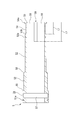
- FIG. 1 It is front sectional drawing which shows the structure of the mechanical seal in an Example. It is front sectional drawing which shows the structure of a sleeve.
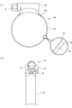
- A is the side view and principal part enlarged view which show the structure of a hose band
- (b) is a front view which shows a hose band. It is a fragmentary sectional view which shows the fixation structure of the sleeve with respect to a rotating shaft.
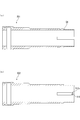
- (A), (b) is front sectional drawing which shows the modification of a sleeve.
- FIG. 1 The mechanical seal according to the embodiment will be described with reference to FIGS.
- the left side of FIG. 1 is the inside of the mechanical seal and the right side of FIG. 1 is the outside of the mechanical seal (atmosphere side).
- a mechanical seal 1 As shown in FIG. 1, a mechanical seal 1 according to this embodiment is used in a shaft seal field such as an automobile or a general industrial machine, and is rotated through a housing 2 and a shaft hole 20 provided in the housing 2. It is attached to seal between the shaft 3 (shaft seal).
- the rotating shaft 3 is generally made of a metal such as stainless steel, and when the shaft sealing device is a pump, an impeller (not shown) is attached to the inside of the machine.
- the mechanical seal 1 is mainly composed of a case 4, a fixed ring 6, a sleeve 5, a collar plate 7, a spring 8, and a rotary ring 9, and is integrated with a set plate 13 before use.
- the cartridge type is configured. As will be described later, the mechanical seal 1 is used with the set plate 13 removed from the sleeve 5.
- the housing 2 has a shape in which the inner periphery inside the machine is wider than the shaft hole 20. Thereby, the impeller which is not shown attached to the machine inner side of the rotating shaft 3 has secured the space which rotates inside the housing 2 (machine interior).
- the shaft hole 20 provided in the housing 2 is formed with a female screw portion 21 on the inner peripheral surface on the inner side of the machine.
- the case 4 is provided with a shaft hole 40 through which the sleeve 5 is inserted, and has an annular shape. Further, the case 4 has a male screw portion 41 formed on the outer peripheral surface inside the machine. According to this, the case 4 can be fixed to the housing 2 by screwing the male screw portion 41 of the case 4 into the female screw portion 21 of the housing 2 described above. Therefore, the case 4 can be easily fixed to the housing 2 without separately using fixing means such as bolts, and the mechanical seal 1 can be attached to the housing 2 with a uniform holding force in the circumferential direction.
- the case 4 is formed with a flange 42 that extends to the outer periphery on the outside of the machine. According to this, when the case 4 is fixed to the housing 2, the end surface 45 on the machine inner side of the flange 42 of the case 4 can be brought into contact with the end surface 22 on the machine outer side of the housing 2. Due to this contact, when the case 4 is fixed to the housing 2, the case 4 and the housing 2 are aligned, so that excessive force does not act on the female screw portion 21 and the male screw portion 41, and the female screw portion 21. In addition, deformation and breakage of the male screw portion 41 can be prevented.
- annular groove 43 is formed on the outer peripheral surface inside the machine from the flange 42, and an O-ring 101 is attached to the annular groove 43.
- the O-ring 101 can be pressure-bonded to the inner peripheral surface of the housing 2 on the machine inner side. Therefore, the gap between the inner peripheral surface of the housing 2 and the outer peripheral surface of the case 4 can be sealed by the O-ring 101.
- the annular groove 43 is disposed so as to face the inner peripheral surface of the housing 2, the diameter of the flange 42 can be shortened to make the case 4 smaller and lighter. Furthermore, since the case 4 is fixed to the housing 2 by the male screw portion 41 provided on the outer periphery thereof, the diameter dimension of the flange 42 can be shortened.
- a fixed ring 6 is fixed to the inner periphery of the inside of the machine via an O-ring 102.
- the fixed ring 6 is provided with a shaft hole 60 through which the sleeve 5 is inserted to form an annular shape.
- the fixed ring 6 is formed with a flange 61 extending to the outer periphery inside the machine.
- the fixed ring 6 is provided with an O-ring 102 on the outer periphery of the reduced diameter portion outside the machine from the flange 61. According to this, when fixing the stationary ring 6 to the case 4, the O-ring 102 can be pressure-bonded to the inner peripheral surface of the case 4 on the machine inner side. Therefore, the gap between the inner peripheral surface of the case 4 and the outer peripheral surface of the stationary ring 6 can be sealed by the O-ring 102.
- the stationary ring 6 is manufactured from SiC by a special conversion method (particulate the carbon surface into SiC, reinforce the surface strength, and combine both the wear resistance of SiC and the self-lubricating property of carbon). Has been. It may also be made of diamond-coated SiC.
- the sleeve 5 is provided with a shaft hole 50 through which the rotary shaft 3 is inserted, and has a tubular shape.
- An annular groove 57 is formed on the inner peripheral surface of the shaft hole 50 provided in the sleeve 5 on the inside of the machine.
- An O-ring 103 is attached to the annular groove 57. According to this, when the rotary shaft 3 is inserted into the shaft hole 50 of the sleeve 5, the O-ring 103 can be pressure-bonded to the outer peripheral surface of the rotary shaft 3. Therefore, the gap between the inner peripheral surface of the sleeve 5 and the outer peripheral surface of the rotary shaft 3 can be sealed by the O-ring 103. In addition, the friction force generated between the O-ring 103 and the rotating shaft 3 is used to make it difficult for the sleeve 5 to move relative to the rotating shaft 3 in the axial direction and the circumferential direction.
- the sleeve 5 is generally made of a metal such as stainless steel, and rotates together with the rotating shaft 3 by being fixed to the rotating shaft 3.
- the fixing structure of the rotating shaft 3 and the sleeve 5 will be described in detail later.
- the sleeve 5 has an outer peripheral surface that is gradually reduced in diameter from the inside of the machine toward the outside of the machine.
- An outer peripheral surface 54 is formed.
- an annular step 55 is formed at the boundary between the first outer peripheral surface 51 and the second outer peripheral surface 52, and the second outer peripheral surface 52 and the third outer peripheral surface 53
- An annular step portion 56 is formed at the boundary portion.
- An annular groove 51 a is formed on the first outer peripheral surface 51 of the sleeve 5 on the inner side of the machine.
- the collar plate 7 is mounted in the annular groove 51a.
- the color plate 7 is fixed so as not to move relative to the sleeve 5 in the axial direction and the circumferential direction.
- a spring 8 is disposed between the color plate 7 and the rotary ring 9 in a compressed state.
- the spring 8 is arranged in a type that uses one spring larger than the shaft diameter of the sleeve 5, that is, a one-coil spring type.
- the spring 8 may be a wave coil spring or the like in addition to the coil spring.
- a guide member 10 is mounted on the second outer peripheral surface 52 of the sleeve 5 on the inner side.
- the guide member 10 is fixed to the second outer peripheral surface 52 of the sleeve 5 so as not to rotate in the circumferential direction by welding.
- the guide member 10 may be assembled to the sleeve 5 by means other than welding.
- a claw extending in the axial direction may be provided on the guide member, and the claw may be inserted into a recess provided in the sleeve.
- the guide member 10 includes a ring-shaped attachment portion 10a and a plurality of L-shaped guide pieces 11, 11,... Provided in the circumferential direction from the attachment portion 10a.
- the attachment portion 10 a of the guide member 10 has substantially the same diameter as the outer periphery of the second outer peripheral surface 52. According to this, when the guide member 10 is mounted on the second outer peripheral surface 52, the guide member 10 moves to the machine inner side (first outer peripheral surface 51 side) of the sleeve 5 by contacting the annular step 55 described above. Is regulated. Therefore, the guide member 10 is easily fixed at a desired mounting position on the outer peripheral surface of the sleeve 5.
- the fixing method of the guide member 10 with respect to the 2nd outer peripheral surface 52 of the sleeve 5 is not restricted to welding, You may fix using uneven
- the guide pieces 11, 11,... Of the guide member 10 are respectively inserted into a plurality of guide recesses 91, 91,... Formed on the inner peripheral surface of the rotary ring 9 on the machine inner side. .. Are formed so as to extend in the axial direction and open to the inside of the machine. According to this, the guide pieces 11, 11,... Are inserted into the guide recesses 91, 91,... To move the rotary ring 9 relative to the sleeve 5 only in the axial direction. Is locked so as not to move relative to the sleeve 5 in the circumferential direction. Therefore, the rotational force of the sleeve 5 is transmitted to the rotating ring 9 by the guide pieces 11, 11,.
- the rotary ring 9 is provided with a shaft hole 90 through which the sleeve 5 is inserted, and has an annular shape. Further, the rotary ring 9 rotates together with the sleeve 5 in a state in which the side end surface on the outer side of the machine is in contact with the side end surface on the inner side of the fixed ring 6.
- the sliding surface S is formed when the side end surface of the rotating ring 9 and the side end surface of the fixed ring 6 abut. Further, the side end surface of the rotating ring 9 is urged toward the outside of the machine when an axial urging force is applied from the spring 8, and is in close contact with the side end surface of the stationary ring 6. According to this, the followability of the side end face of the rotating ring 9 with respect to the side end face of the fixed ring 6 can be enhanced. Therefore, the sealing performance on the sliding surface S of the mechanical seal 1 can be enhanced.
- the rotary ring 9 is provided with an O-ring 104 on the inner peripheral surface inside the machine. According to this, when inserting the rotary ring 9 into the sleeve 5, the O-ring 104 can be pressure-bonded to the second outer peripheral surface 52 of the sleeve 5. Therefore, the gap between the inner peripheral surface of the rotating ring 9 and the second outer peripheral surface 52 of the sleeve 5 can be sealed by the O-ring 104.
- the holding plate 12 is attached to the rotary ring 9 by press-fitting or the like on the inner peripheral surface of the machine inner side than the position where the O-ring 104 is mounted.
- the holding plate 12 regulates the movement of the O-ring 104 attached to the inner peripheral surface of the rotating ring 9 toward the inside of the machine.
- the rotary ring 9 is provided with an annular convex portion 92 extending on the inner diameter side on the inner peripheral surface on the outer side of the machine. According to this, the diameter of the shaft hole 90 on the machine outside where the side end surface of the rotary ring 9 described above is formed can be reduced, and the position of the sliding surface S can be brought closer to the inner diameter side. Therefore, the load applied to the sliding surface S when the mechanical seal 1 is used can be reduced.
- the annular convex portion 92 can be brought into contact with the annular step portion 56. Therefore, it is possible to easily align the rotary ring 9 with the sleeve 5 in the axial direction.
- the rotating ring 9 is manufactured from SiC by a special conversion method (partially converting the carbon surface to SiC, reinforcing the surface strength, and combining both the wear resistance of SiC and the self-lubricating property of carbon). Has been. It may also be made of diamond-coated SiC.
- annular groove 53a is formed outside the machine.
- a C-ring set plate 13 is mounted in the annular groove 53a.
- the set plate 13 can be brought into contact with an annular recess 44 formed on the outer periphery of the shaft hole 40 of the case 4 inserted through the sleeve 5 by being mounted in the annular groove 53a.
- each member inserted through the sleeve 5 can be integrally held between the inner color plate 7 and the outer set plate 13 using the biasing force of the spring 8. Therefore, the mechanical seal 1 can be configured as a cartridge type.
- the cartridge type mechanical seal 1 is inserted from the inside of the machine (on the color plate 7 side) into the shaft hole 20 of the housing 2 from the outside of the machine, and the male screw part 41 of the case 4 is inserted into the female screw part 21 of the housing 2. By being screwed into the housing 2, it can be easily fixed to the housing 2.
- the set plate 13 is removed from the sleeve 5 after fixing the case 4 to the housing 2.
- the fourth outer peripheral surface 54 of the sleeve 5 is formed with slits 58, 58, 58, 58 extending in the axial direction from the end portion on the outside of the machine.
- the slits 58, 58, 58, 58 are equally arranged every 90 degrees with respect to the circumferential direction of the sleeve 5.
- leg portions 59 that substantially constitute the fourth outer peripheral surface 54 of the sleeve 5 are formed between the slits 58 adjacent to each other in the circumferential direction.
- the slits 58, 58, 58, 58 extend from the end of the third outer peripheral surface 53 to the inside of the predetermined size machine. That is, the axial dimension L2 of the slits 58, 58, 58, 58 is longer than the axial dimension L1 of the fourth outer peripheral surface 54.
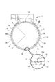
- the cross section of the sleeve 5 shown in FIGS. 1, 2 and 5 is not a cross section obtained by cutting the sleeve 5 by one plane, but is shown by, for example, an imaginary line AA ′ in FIG.
- the sleeve 5 is illustrated as a cross-sectional view cut along two planes orthogonal to each other at the axis. Therefore, in FIG. 1, FIG. 2 and FIG. 5, only the slit 58 on the right side of FIG. 4 among the slits 58, 58, 58, 58 equally distributed every 90 degrees with respect to the circumferential direction of the sleeve 5 is provided. It is shown.
- the hose band 14 (clamping member) is formed on the fourth outer peripheral surface 54 of the sleeve 5 in a state where the rotary shaft 3 is inserted into the shaft hole 50 provided in the sleeve 5. Installed.
- the hose band 14 includes a band portion 15 having a width substantially the same as the axial dimension L1 of the fourth outer peripheral surface 54 of the sleeve 5, and one of the band portions 15. It is mainly composed of a holding case 16 to which the end is fixed, and a tightening bolt 17 provided on the holding case 16. Further, the hose band 14 deforms the band portion 15 into a ring shape, and tightens or loosens the tightening bolt 17 in a state where the free end portion (the other end portion) of the band portion 15 is passed through the holding case 16. Thus, the tightening force of the band portion 15 can be adjusted.
- the band portion 15 is made of metal or resin, and has a plurality of through holes 19, 19,... Extending in the width direction (see FIG. 3B). Further, a plurality of convex portions 18, 18,... Projecting toward the inner diameter side are formed on the inner peripheral surface of the band portion 15 (see an enlarged view of FIG. 3A).
- the hose band 14 is attached to the fourth outer peripheral surface 54 of the sleeve 5 with the rotary shaft 3 inserted through the shaft hole 50 provided in the sleeve 5, and then tightened.
- the sleeve 5 can be fixed to the rotating shaft 3 by tightening the rotating shaft 3 and the fourth outer peripheral surface 54 of the sleeve 5 with the band portion 15.
- the hose band 14 is attached to the fourth outer peripheral surface 54, and the end portion on the machine inner side of the band portion 15 is formed at the boundary portion between the third outer peripheral surface 53 and the fourth outer peripheral surface 54.
- the portion 53b By contacting the portion 53b, the movement of the sleeve 5 toward the machine inner side (the third outer peripheral surface 53 side) is restricted. Therefore, the hose band 14 can be easily fixed at a desired attachment position on the outer peripheral surface of the sleeve 5.
- the plurality of convex portions 18, 18,... Formed on the inner peripheral surface of the band portion 15 are hooked on the peripheral portions 58 a of the slits 58 that are equally arranged on the sleeve 5 every 90 degrees. According to this, the hose band 14 can be locked so as not to move relative to the sleeve 5 in the circumferential direction, and the tightening force of the hose band 14 (band portion 15) can be maintained.
- the mechanical seal 1 has the hose band from the circumferential direction with respect to the fourth outer peripheral surface 54 of the sleeve 5 in a state where the rotary shaft 3 is inserted into the shaft hole 50 provided in the sleeve 5.
- the sleeve 5 can be stably fixed to the rotary shaft 3 by tightening with the 14 band portions 15. And since the sleeve 5 is pressed substantially uniformly over the entire circumference without being locally pressed against the rotating shaft 3, the sleeve 5 and the rotating shaft 3 can be aligned with each other. Therefore, high sealing performance can be maintained without affecting the sliding torque of the mechanical seal 1.
- the band portion 15 is further reduced in diameter in a state where the convex portion 18 is hooked on the peripheral portion 58a of the slit 58, whereby the leg portion 59 of the sleeve 5 moves slightly in the circumferential direction.
- the leg portion 59 of the sleeve 5 is slightly inclined with respect to the rotation shaft 3. Therefore, it is difficult for the hose band 14 to move relative to the sleeve 5 in the axial direction.
- the leg portion 59 of the sleeve 5 is slightly reduced in diameter in the radial direction.
- the axial dimension L2 of the slits 58, 58, 58, 58 of the sleeve 5 is longer than the axial dimension L1 of the fourth outer peripheral surface 54 of the sleeve 5 fixed by the band portion 15 of the hose band 14. It has become.
- the leg portion 59 of the sleeve 5 is reduced in diameter substantially uniformly in the axial direction, in other words, the leg portion 59 of the sleeve 5 is axially reduced.
- the diameter is not reduced by being inclined over the range. Therefore, the hose band 14 can be hardly detached from the sleeve 5 in the axial direction.
- the fourth outer peripheral surface 54 of the sleeve 5 has the smallest thickness compared to the first outer peripheral surface 51, the second outer peripheral surface 52, and the third outer peripheral surface 53. Further, slits 58, 58, 58, 58 are formed in the fourth outer peripheral surface 54 of the sleeve 5. According to this, it becomes easy to reduce the diameter of the fourth outer peripheral surface 54 of the sleeve 5 in the inner diameter direction. Therefore, when the fourth outer peripheral surface 54 of the sleeve 5 is tightened by the band portion 15 of the hose band 14, the inner peripheral surface of the sleeve 5 can be easily brought into contact with the outer peripheral surface of the rotary shaft 3. 3 can be fixed more firmly.
- the slits 58, 58, 58, 58 are open to the outside of the sleeve 5 in the axial direction, and a plurality of slits 58, 58, 58, 58 are formed in the circumferential direction of the sleeve 5. According to this, since the front end of the leg portions 59, 59, 59, 59 of the sleeve 5 functions as a free end, it is possible to increase the degree of freedom in which the sleeve 5 is reduced in diameter as the hose band 14 is tightened. .
- the sleeve 50 is formed with a fifth outer peripheral portion 54 a protruding outward from the fourth outer peripheral surface 54 toward the outer diameter side. According to this, the hose band 14 attached to the fourth outer peripheral surface 54 of the sleeve 50 is restricted from moving in the axial direction by the fifth outer peripheral portion 54a. Therefore, the fixed state of the rotating shaft 3 and the sleeve 50 can be maintained.
- the fifth outer peripheral portion may be omitted on the outer side of the sleeve 501.
- the sleeve 501 can be easily manufactured.
- slits 512, 512, 512 and 512 are formed in the sleeve 502 in the shape of a long hole extending in the axial direction, and the outer periphery of the machine 502 is closed. According to this, the convex portions 18, 18,...
- the material of the O-rings 101, 102, 103, 104 in the above embodiment is fluorine rubber, nitrile rubber, H-NBR, EPDM, perfluoroelastomer or the like.
- the material of the stationary ring 6 and the rotating ring 9 may be an ultra-hard material such as silicon carbide, tungsten carbide, carbon, and other ceramics.
- the slits 58, 58, 58, 58 are described as being equally arranged every 90 degrees at the end of the sleeve 5 outside the machine.
- the present invention is not limited to this.
- the interval or the like may be freely configured.
- the slit 58 was demonstrated as an aspect formed in a substantially rectangular shape, it is not restricted to this,
- the shape of a slit is the uneven
- the shape and the formation method of the convex portions 18, 18,... May be freely configured as long as they are hooked by the slit 58.
- a burr formed on the inner peripheral surface of the band portion 15 may be used as the convex portion 18.
- the convex portion 18 may be disposed only at a position that matches the position of the slit 58.
- the tip 15a of the band portion 15 may be hooked on the slit 58 as the convex portion 18 (see FIG. 3A).
- the axial dimension of the slit is formed at a position where the convex portion formed on the inner peripheral surface of the band portion of the hose band is hooked when the rotating shaft and the sleeve are fixed by the hose band, for example,
- the same dimension as the axial dimension of the fourth outer peripheral surface 54 may be used, or it may be smaller than the axial dimension of the fourth outer peripheral surface 54.
- band-shaped member has been described as an example of the tightening member, the shape is not limited and may be linear.
Landscapes
- Engineering & Computer Science (AREA)
- General Engineering & Computer Science (AREA)
- Mechanical Engineering (AREA)
- Mechanical Sealing (AREA)
Abstract
スリーブを回転軸に精度良く固定することで、このフランジに設けられた回転環と静止環との摺動トルクを均一に安定させ、高い密封性を維持することができるメカニカルシールを提供する。 ハウジング2と回転軸3との間に形成した軸封部に装着され、ハウジング2側の固定環6と回転軸3側の回転環9とを摺動させることで、軸封部をシールするメカニカルシール1であって、回転軸3の外周面に挿嵌され、該回転軸3と共に回転するスリーブ5を備え、スリーブ5の外径側に、該スリーブ5を回転軸3に対し周方向に亘って緊締する緊締部材14が設けられている。
Description
本発明は、ハウジングと回転軸との間に形成した軸封部に装着され、ハウジング側の固定環と回転軸側の回転環とを摺動させることで、この軸封部をシールするメカニカルシールに関する。
従来のメカニカルシールは、回転軸の外周面に対しスリーブを外嵌して固定し、このスリーブに回転環を設けることで、回転軸に供回りする回転環と、ハウジングに固定した固定環とを摺動させ、ハウジングと回転軸との間に形成した軸封部をシールしている。
スリーブの回転軸への固定について、より詳しくは、回転軸に挿通したスリーブの軸方向の一端にストッパーリングを外嵌し、このストッパーリングに径方向に螺合した第1セットスクリューをスリーブの外周面に押圧し締め付けることで、ストッパーリングをスリーブに固定するとともに、このストッパーリングに径方向に螺合した第2セットスクリューをスリーブのセット孔を通して回転軸の外周面に押圧し締め付けることで、スリーブを回転軸に対して固定するものがある(例えば、特許文献1参照)。
しかしながら、特許文献1にあっては、スリーブの軸方向の一端で螺合した第1セットスクリューが、回転軸の周方向の所定位置で押圧されることで、スリーブを回転軸に対し固定しているため、スリーブが回転軸の周方向に対し局所的に押圧される結果、スリーブと回転軸との軸心が一致せず、このスリーブに設けられた回転環と静止環との摺動トルクに影響を与え、高い密封性を維持できない虞が生じるという問題がある。
本発明は、このような問題点に着目してなされたもので、スリーブを回転軸に精度良く固定することで、このフランジに設けられた回転環と静止環との摺動トルクを均一に安定させ、高い密封性を維持することができるメカニカルシールを提供することを目的とする。
前記課題を解決するために、本発明のメカニカルシールは、
ハウジングと回転軸との間に形成した軸封部に装着され、前記ハウジング側の固定環と前記回転軸側の回転環とを摺動させることで、前記軸封部をシールするメカニカルシールであって、
前記回転軸の外周面に挿嵌され、該回転軸と共に回転するスリーブを備え、前記スリーブの外径側に、該スリーブを前記回転軸に対し周方向に亘って緊締する緊締部材が設けられていることを特徴としている。
この特徴によれば、緊締部材が、スリーブの外周面を周方向に亘り緊締することで、スリーブが、回転軸に対し局所的に押圧されることなく全周に亘り略均一に押圧されるため、スリーブと回転軸との軸心を一致させることができ、メカニカルシールの摺動トルクに影響を与えず高い密封性を維持することができる。
ハウジングと回転軸との間に形成した軸封部に装着され、前記ハウジング側の固定環と前記回転軸側の回転環とを摺動させることで、前記軸封部をシールするメカニカルシールであって、
前記回転軸の外周面に挿嵌され、該回転軸と共に回転するスリーブを備え、前記スリーブの外径側に、該スリーブを前記回転軸に対し周方向に亘って緊締する緊締部材が設けられていることを特徴としている。
この特徴によれば、緊締部材が、スリーブの外周面を周方向に亘り緊締することで、スリーブが、回転軸に対し局所的に押圧されることなく全周に亘り略均一に押圧されるため、スリーブと回転軸との軸心を一致させることができ、メカニカルシールの摺動トルクに影響を与えず高い密封性を維持することができる。
前記緊締部材が設けられる前記スリーブの周壁に、軸方向に延びるスリットが形成されていることを特徴としている。
この特徴によれば、スリーブの周壁に、軸方向に延びるスリットが形成されているため、緊締部材の締付けにより、スリーブが内径方向に縮径し易く、回転軸に強固に固定される。
この特徴によれば、スリーブの周壁に、軸方向に延びるスリットが形成されているため、緊締部材の締付けにより、スリーブが内径方向に縮径し易く、回転軸に強固に固定される。
前記緊締部材の内周面に、内径側に突出し前記スリットに係止される突出部が設けられていることを特徴としている。
この特徴によれば、緊締部材の突出部がスリットに係止されることで、緊締バンドがスリーブに対し周方向に位置固定されるため、回転軸の回転によってスリーブからの緊締部材が脱嵌を抑制できる。
この特徴によれば、緊締部材の突出部がスリットに係止されることで、緊締バンドがスリーブに対し周方向に位置固定されるため、回転軸の回転によってスリーブからの緊締部材が脱嵌を抑制できる。
前記スリットは、前記スリーブの軸方向の先端に開放され、且つ前記スリーブの周方向に複数形成されていることを特徴としている。
この特徴によれば、スリーブの軸方向の先端が自由端として機能するため、緊締部材の緊締に伴いスリーブが縮径する自由度を高めることができる。
この特徴によれば、スリーブの軸方向の先端が自由端として機能するため、緊締部材の緊締に伴いスリーブが縮径する自由度を高めることができる。
前記スリットは、前記緊締部材よりも軸方向に幅広に形成されていることを特徴としている。
この特徴によれば、幅広のスリットが形成されたスリーブが、緊締部材の全幅に亘り均一に縮径されるため、緊締部材が軸方向に脱嵌する虞を回避できる。
この特徴によれば、幅広のスリットが形成されたスリーブが、緊締部材の全幅に亘り均一に縮径されるため、緊締部材が軸方向に脱嵌する虞を回避できる。
前記スリーブに外嵌され前記固定環が取り付けられるケースの外周面に雄ネジ部が設けられるとともに、前記ハウジングの内周面に前記ネジ部に螺合する雌ネジ部が設けられることを特徴としている。
この特徴によれば、スリーブに外嵌されたケースの雄ネジ部をハウジングの雌ネジ部に螺合するだけで、ケースをハウジングに取り付けることができるため、メカニカルシールの取付部品の点数を削減できるばかりか、周方向に亘り均一な保持力でメカニカルシールを取付けることができる。
この特徴によれば、スリーブに外嵌されたケースの雄ネジ部をハウジングの雌ネジ部に螺合するだけで、ケースをハウジングに取り付けることができるため、メカニカルシールの取付部品の点数を削減できるばかりか、周方向に亘り均一な保持力でメカニカルシールを取付けることができる。
本発明に係るメカニカルシールを実施するための形態を実施例に基づいて以下に説明する。
実施例に係るメカニカルシールにつき、図1から図5を参照して説明する。以下、図1の紙面左側をメカニカルシールの機内側とし、図1の紙面右側をメカニカルシールの機外側(大気側)として説明する。
図1に示されるように、本実施例に係るメカニカルシール1は、自動車、一般産業機械等の軸封分野で用いられ、ハウジング2と、該ハウジング2に設けられる軸孔20に挿通される回転軸3との間(軸封部)をシールするために取り付けられる。尚、回転軸3は、一般にステンレス鋼製等の金属製であり、軸封する機器がポンプの場合には、機内側に図示しない羽根車が取り付けられている。
メカニカルシール1は、ケース4と、固定環6と、スリーブ5と、カラープレート7と、スプリング8と、回転環9と、から主に構成されており、使用前においてはセットプレート13により一体とされたカートリッジ型に構成されるものである。このメカニカルシール1は、後述するように、セットプレート13をスリーブ5から取り外した状態で使用するものである。
ハウジング2は、機内側の内周が軸孔20よりも拡開された形状を成している。これにより、回転軸3の機内側に取り付けられる図示しない羽根車が、ハウジング2の内部(機内)で回転する空間を確保している。また、ハウジング2に設けられる軸孔20には、機内側の内周面に雌ネジ部21が形成されている。
ケース4には、スリーブ5が挿通される軸孔40が設けられ、環状を成している。また、ケース4には、機内側の外周面に雄ネジ部41が形成されている。これによれば、ケース4の雄ネジ部41を前述したハウジング2の雌ネジ部21にねじ込むことにより、ケース4をハウジング2に固定することができる。そのため、ボルト等の固定手段を別途用いることなく、ケース4をハウジング2に容易に固定することができるばかりか、周方向に亘り均一な保持力でメカニカルシール1をハウジング2に取付けることができる。
また、ケース4には、機外側の外周に延出するフランジ42が形成されている。これによれば、ケース4をハウジング2に固定するとき、ケース4のフランジ42の機内側の一端面45をハウジング2の機外側の端面22に当接させることができる。この当接により、ケース4をハウジング2に固定するとき、ケース4とハウジング2の位置合わせが行われ、雌ネジ部21及び雄ネジ部41に過剰な力が働くことがなくなり、雌ネジ部21及び雄ネジ部41の変形や破損等を防ぐことができる。
また、ケース4には、フランジ42よりも機内側の外周面に環状溝43が形成されており、この環状溝43には、Oリング101が装着されている。これによれば、ケース4をハウジング2に固定するとき、Oリング101をハウジング2の機内側の内周面に圧着させることができる。そのため、ハウジング2の内周面とケース4の外周面との間の隙間をOリング101によってシールすることができる。
また、環状溝43をハウジング2の内周面に対向して配置しているため、フランジ42の径寸法を短くしてケース4を小型・軽量化することができる。さらに、ケース4をその外周に設けた雄ネジ部41によりハウジング2に固定しているため、フランジ42の径寸法を短くすることができる。
また、ケース4には、機内側の内周に固定環6がOリング102を介して固定されている。固定環6には、スリーブ5が挿通される軸孔60が設けられ、環状を成している。また、固定環6には、機内側の外周に延出するフランジ61が形成されている。
また、固定環6には、フランジ61よりも機外側の縮径部分の外周にOリング102が装着されている。これによれば、固定環6をケース4に固定するとき、Oリング102をケース4の機内側の内周面に圧着させることができる。そのため、ケース4の内周面と固定環6の外周面との間の隙間をOリング102によってシールすることができる。
尚、固定環6は、特殊転換法(カーボン表面を部分的にSiC化し、表面強度を補強し、SiCの耐摩耗性とカーボンの自己潤滑性の両方を兼ね備えるようにすること)によるSiCから製作されている。また、ダイヤモンドコーティングしたSiCにより製作されてもよい。
図1及び図2に示されるように、スリーブ5には、回転軸3が挿通される軸孔50が設けられ、管状を成している。また、スリーブ5に設けられる軸孔50の機内側の内周面には、環状溝57が形成されており、この環状溝57には、Oリング103が装着されている。これによれば、スリーブ5の軸孔50に回転軸3が挿通されるとき、Oリング103を回転軸3の外周面に圧着させることができる。そのため、スリーブ5の内周面と回転軸3の外周面との間の隙間をOリング103によってシールすることができる。さらに、Oリング103と回転軸3との間に生じる摩擦力を利用して、スリーブ5を回転軸3に対して軸方向及び周方向に相対移動し難くしている。
尚、スリーブ5は、一般にステンレス鋼製等の金属製であり、回転軸3に固定されることにより、回転軸3と共に回転する。尚、回転軸3とスリーブ5の固定構造については後段にて詳述する。
また、スリーブ5は、外周面が機内側から機外側へ向けて段階的に縮径しており、機内側から順に第1外周面51、第2外周面52、第3外周面53及び第4外周面54が形成されている。さらに、スリーブ5の外周の径の違いによって、第1外周面51と第2外周面52との境界部分には、環状段部55が形成され、第2外周面52と第3外周面53との境界部分には、環状段部56が形成されている。
スリーブ5の第1外周面51には、機内側に環状溝51aが形成されている。この環状溝51aには、カラープレート7が装着されている。尚、カラープレート7は、スリーブ5に対して軸方向及び周方向に相対移動しないように固定されている。
また、周知のように、カラープレート7と回転環9との間には、圧縮された状態でスプリング8が配置されている。スプリング8は、スリーブ5の軸径よりも大きいスプリングを1本使用する形式、すなわちワンコイルスプリング型で配置されている。尚、スプリング8は、コイルスプリングの他に、ウェーブコイルスプリング等を使用してもよい。
スリーブ5の第2外周面52には、機内側にガイド部材10が装着されている。ガイド部材10は、スリーブ5の第2外周面52に対して溶接されることにより、周方向に回動不能に固定されている。なお、ガイド部材10はスリーブ5に溶接以外によって組み付けられていてもよく、例えばガイド部材に軸方向に延びる爪を設けこの爪をスリーブに設けた凹部に挿入ればよい。また、ガイド部材10は、リング状の取付部10aと、該取付部10aから周方向に複数設けられたL字状のガイド片11,11,…と、から構成されている。さらに、ガイド部材10の取付部10aは、第2外周面52の外周と略同一径を成している。これによれば、ガイド部材10は、第2外周面52に装着された状態で、前述した環状段部55に当接することにより、スリーブ5の機内側(第1外周面51側)への移動が規制されている。そのため、ガイド部材10は、スリーブ5の外周面における所望の取り付け位置に固定しやすくなっている。尚、スリーブ5の第2外周面52に対するガイド部材10の固定方法は、溶接に限らず、凹凸嵌合を利用して固定されてもよい。
また、ガイド部材10のガイド片11,11,…は、自由端部が回転環9の機内側の内周面に形成される複数のガイド用凹部91,91,…にそれぞれ挿入されている。ガイド用凹部91,91,…は、軸方向へ延び機内側に開放するように形成されている。これによれば、ガイド片11,11,…は、ガイド用凹部91,91,…に挿入されることにより、回転環9をスリーブ5に対して軸方向へのみ相対移動させるとともに、回転環9をスリーブ5に対して周方向へ相対移動させないように係止する。そのため、回転環9には、ガイド片11,11,…によりスリーブ5の回転力が伝達され、スリーブ5と共に回転する。
回転環9には、スリーブ5が挿通される軸孔90が設けられ、環状を成している。また、回転環9は、機外側の側端面を固定環6の機内側の側端面に当接させた状態で、スリーブ5と共に回転する。尚、回転環9の側端面と固定環6の側端面とが当接することにより摺動面Sが形成される。また、回転環9の側端面は、スプリング8から軸方向の付勢力が負荷されることにより、機外側に付勢され、固定環6の側端面に対して密着している。これによれば、固定環6の側端面に対する回転環9の側端面の追従性を高めることができる。そのため、メカニカルシール1の摺動面Sにおけるシール性を高めることができる。
また、回転環9には、機内側の内周面にOリング104が装着されている。これによれば、回転環9をスリーブ5に挿通するとき、Oリング104をスリーブ5の第2外周面52に圧着させることができる。そのため、回転環9の内周面とスリーブ5の第2外周面52との間の隙間をOリング104によってシールすることができる。
また、回転環9には、機内側の内周面において、Oリング104の装着位置よりも機内側の位置に保持プレート12が圧入などにより取り付けられている。保持プレート12は、回転環9の内周面に装着されたOリング104の機内側への移動を規制している。
また、回転環9には、機外側の内周面に内径側に延出する環状凸部92が設けられている。これによれば、前述した回転環9の側端面が形成される機外側の軸孔90の径を小さくすることができ、摺動面Sの位置を内径側に近づけることができる。そのため、メカニカルシール1の使用時に摺動面Sにかかる負荷を低減することができる。
また、回転環9をスリーブ5に挿通させる際には、環状凸部92を環状段部56に当接させることができる。そのため、回転環9のスリーブ5に対する軸方向の位置合わせを容易に行うことができる。
尚、回転環9は、特殊転換法(カーボン表面を部分的にSiC化し、表面強度を補強し、SiCの耐摩耗性とカーボンの自己潤滑性の両方を兼ね備えるようにすること)によるSiCから製作されている。また、ダイヤモンドコーティングしたSiCにより製作されてもよい。
スリーブ5の第3外周面53には、機外側に環状溝53aが形成されている。この環状溝53aには、Cリング状のセットプレート13が装着される。セットプレート13は、環状溝53aに装着されることにより、スリーブ5に挿通されたケース4の軸孔40の機外側の周縁に形成される環状凹部44に当接させることができる。これによれば、スリーブ5に挿通された各部材を、スプリング8の付勢力を利用して機内側のカラープレート7と機外側のセットプレート13との間に一体保持することができる。そのため、メカニカルシール1をカートリッジ型に構成することができる。
カートリッジ型に構成されたメカニカルシール1は、機内側(カラープレート7側)からハウジング2の軸孔20に対して機外側から挿通し、ケース4の雄ネジ部41をハウジング2の雌ネジ部21にねじ込むことにより、ハウジング2に容易に固定することができる。尚、セットプレート13は、ケース4をハウジング2に固定した後にスリーブ5から取り外される。
図2及び図4に示されるように、スリーブ5の第4外周面54には、機外側の端部から軸方向に延びるスリット58,58,58,58が形成されている。スリット58,58,58,58は、スリーブ5の周方向に対して90度毎に等配されている。また、周方向に隣接するスリット58,58の間には、スリーブ5の第4外周面54を実質的に構成する脚部59がそれぞれ形成されている。さらに、スリット58,58,58,58は、第3外周面53の機外側の端部から所定寸法機内側まで延びている。すなわち、スリット58,58,58,58の軸方向の寸法L2は、第4外周面54の軸方向の寸法L1よりも長くなっている。
尚、説明の便宜上、図1、図2及び図5に示されるスリーブ5の断面は、スリーブ5を1つの平面により切断した断面ではなく、例えば、図4の仮想線A-A’に示されるように、スリーブ5を軸心で直交する2つの平面により切断した断面図として図示している。そのため、図1、図2及び図5においては、スリーブ5の周方向に対して90度毎に等配されるスリット58,58,58,58の内、図4の紙面右側のスリット58のみを図示している。
次いで、回転軸3へのスリーブ5の固定構造について図1、図3及び図4を用いて説明する。図1及び図4に示されるように、スリーブ5に設けられる軸孔50に回転軸3が挿通された状態で、スリーブ5の第4外周面54には、ホースバンド14(締締部材)が装着される。
図3(a)に示されるように、ホースバンド14は、スリーブ5の第4外周面54の軸方向の寸法L1と略同一寸法の幅を有するバンド部15と、該バンド部15の一方の端部が固定される保持ケース16と、該保持ケース16に設けられる締付ボルト17と、から主に構成されている。また、ホースバンド14は、バンド部15を輪状に変形させ、バンド部15の自由端部(他方の端部)を保持ケース16内に通した状態で、締付ボルト17を締めたり緩めたりすることにより、バンド部15の締め付け力を調整することができる。尚、バンド部15は、金属または樹脂製であり、幅方向に延びる複数の貫通孔19,19,…が長手方向に亘って設けられている(図3(b)参照)。また、バンド部15の内周面には、内径側に突出する複数の凸部18,18,…が形成されている(図3(a)の拡大図参照)。
これによれば、図4に示されるように、スリーブ5に設けられる軸孔50に回転軸3が挿通された状態で、スリーブ5の第4外周面54にホースバンド14を装着した後、締付ボルト17を締めることにより、回転軸3及びスリーブ5の第4外周面54をバンド部15で締め付けてスリーブ5を回転軸3に固定することができる。
また、ホースバンド14は、第4外周面54に装着された状態で、バンド部15の機内側の端部が第3外周面53と第4外周面54との境界部分に形成される環状段部53bに当接することにより、スリーブ5の機内側(第3外周面53側)への移動が規制されている。そのため、ホースバンド14は、スリーブ5の外周面における所望の取り付け位置に簡単に固定することができる。
また、このとき、バンド部15の内周面に形成される複数の凸部18,18,…が、スリーブ5に90度毎に等配された各スリット58の周縁部58aに引っ掛る。これによれば、ホースバンド14がスリーブ5に対して周方向に相対移動しないように係止することができ、ホースバンド14(バンド部15)の締め付け力を維持することができる。
以上説明したように、本実施例のメカニカルシール1は、スリーブ5に設けられる軸孔50に回転軸3が挿通された状態で、スリーブ5の第4外周面54に対して周方向からホースバンド14のバンド部15で締め付けることにより、スリーブ5を回転軸3に対して安定して固定することができる。そして、スリーブ5は、回転軸3に対して局所的に押圧されることなく全周に亘り略均一に押圧されるため、スリーブ5と回転軸3との軸心を一致させることができる。そのため、メカニカルシール1の摺動トルクに影響を与えず高い密封性を維持することができる。
また、スリーブ5とホースバンド14のバンド部15の熱膨張率の違い等により、ホースバンド14のバンド部15がスリーブ5に対して周方向に相対移動した場合でも、バンド部15の内周面に形成される複数の凸部18,18,…のいずれかがスリーブ5に形成される各スリット58の周縁部58aに引っ掛ることにより、回転軸3とスリーブ5との固定状態を維持することができる。
また、1つのスリット58に対して凸部18を多数配置する構成としているので、ホースバンド14の取り付け位置を意識せずともスリット58の周縁部58aに凸部18が引っ掛かるため、スリーブ5に対するホースバンド14の位置決めが簡単である。
また、ホースバンド14による緊締時には、凸部18がスリット58の周縁部58aに引っ掛かった状態でバンド部15がさらに縮径することにより、スリーブ5の脚部59が周方向に僅かに移動する。これにより、スリーブ5の脚部59は、回転軸3に対して僅かに傾いた状態となる。そのため、ホースバンド14がスリーブ5に対して軸方向に相対移動し難くなっている。
また、ホースバンド14の締め付けにより、スリーブ5の脚部59は僅かに径方向に縮径される。ここで、ホースバンド14のバンド部15により固定されるスリーブ5の第4外周面54の軸方向の寸法L1よりも、スリーブ5のスリット58,58,58,58の軸方向の寸法L2が長くなっている。これによれば、ホースバンド14のバンド部15の位置において、スリーブ5の脚部59は、軸方向に亘って略均一に縮径される、言い換えると、スリーブ5の脚部59は、軸方向に亘って傾いて縮径されることがない。そのため、ホースバンド14がスリーブ5から軸方向に脱嵌し難くできる。
また、図2に示されるように、スリーブ5の第4外周面54は、第1外周面51、第2外周面52及び第3外周面53と比べて、厚みが最も薄くなっている。さらに、スリーブ5の第4外周面54にスリット58,58,58,58が形成されている。これによれば、スリーブ5の第4外周面54を内径方向に縮径させやすくなる。そのため、ホースバンド14のバンド部15によりスリーブ5の第4外周面54を締め付ける際に、回転軸3の外周面に対してスリーブ5の内周面を当接させやすくなり、スリーブ5を回転軸3に対してより強固に固定することができる。
また、スリット58,58,58,58は、スリーブ5の軸方向の機外側に開放され、且つスリーブ5の周方向に複数形成されている。これによれば、スリーブ5の脚部59,59,59,59の機外側の先端が自由端として機能するため、ホースバンド14による緊締に伴いスリーブ5が縮径する自由度を高めることができる。
また、図2に示されるように、スリーブ50には、第4外周面54よりも機外側に外径側に突出する第5外周部54aが形成されている。これによれば、スリーブ50の第4外周面54に装着されるホースバンド14は、軸方向への動きを第5外周部54aによって規制される。そのため、回転軸3とスリーブ50との固定状態を維持することができる。
尚、スリーブ5の変形例として次のようなものがある。図5(a)に示されるように、スリーブ501において機外側に第5外周部を省略してもよく、この場合スリーブ501の製作が容易である。また、図5(b)に示されるように、スリーブ502には、スリット512,512,512,512が、軸方向に延びる長孔状に形成され、機外側の周縁が閉塞されている。これによれば、ホースバンド14のバンド部15の内周面に形成される凸部18,18,…が、スリーブ502の各スリット512の機外側を構成する周縁512aにより機外側に移動しないように係止することができる。そのため、回転軸3とスリーブ502との固定状態を維持することができる。
尚、前記実施例におけるOリング101,102,103,104の材質は、フッ素ゴム、ニトリルゴム、H-NBR、EPDM、パーフロロエラストマ等である。
また、ケース4の雄ネジ部41をハウジング2の雌ネジ部21にねじ込むことによりケース4をハウジング2に固定した後、さらにボルト等でこれらを固定してもよい。
また、固定環6及び回転環9の材質は、シリコンカーバイド、タングステンカーバイト、カーボン、その他のセラミックス等の超硬質材料であってもよい。
以上、本発明の実施例を図面により説明してきたが、具体的な構成はこれら実施例に限られるものではなく、本発明の要旨を逸脱しない範囲における変更や追加があっても本発明に含まれる。
例えば、前記実施例では、スリーブ5の機外側の端部にスリット58,58,58,58が90度毎に等配されている態様として説明したが、これに限らず、スリットの数、配置間隔等は自由に構成されてよい。
また、前記実施例では、スリット58は略長方形状に形成される態様として説明したが、これに限らず、スリットの形状は、スリットの周縁部にホースバンドの内周面に形成される凹凸部を引っ掛けられるものであれば、形状は自由に構成されてよい。
また、凸部18,18,…の形状や形成方法は、スリット58に引っ掛けられるものであれば形状や配置等は自由に構成されてよい。例えば、バンド部15に貫通孔19を打ち抜き形成する際に、バンド部15の内周面に形成されるバリを凸部18として用いてもよい。また、凸部18をスリット58の位置に合った位置にのみ配置するものであってもよい。また、バンド部15の先端15aを凸部18としてスリット58に引っ掛けるものであってもよい(図3(a)参照)。
また、スリットの軸方向の寸法は、回転軸とスリーブをホースバンドにより固定した際に、ホースバンドのバンド部の内周面に形成される凸部を引っ掛けられる位置に形成されていれば、例えば、第4外周面54の軸方向の寸法と同一寸法であってもよいし、第4外周面54の軸方向の寸法よりも小さくてもよい。
また、緊締部材として、バンド形状のものを例に説明したが、その形状は問わず、線状であってもよい。
1 メカニカルシール
2 ハウジング
3 回転軸
4 ケース
5 スリーブ
6 固定環
7 カラープレート
8 スプリング
9 回転環
10 ガイド部材
12 保持プレート
13 セットプレート
14 ホースバンド(緊締部材)
15 バンド部
18 凸部
21 雌ネジ部
41 雄ネジ部
51 第1外周面
52 第2外周面
53 第3外周面
54 第4外周面
58 スリット
59 脚部
101~104 Oリング
S 摺動面
2 ハウジング
3 回転軸
4 ケース
5 スリーブ
6 固定環
7 カラープレート
8 スプリング
9 回転環
10 ガイド部材
12 保持プレート
13 セットプレート
14 ホースバンド(緊締部材)
15 バンド部
18 凸部
21 雌ネジ部
41 雄ネジ部
51 第1外周面
52 第2外周面
53 第3外周面
54 第4外周面
58 スリット
59 脚部
101~104 Oリング
S 摺動面
Claims (6)
- ハウジングと回転軸との間に形成した軸封部に装着され、前記ハウジング側の固定環と前記回転軸側の回転環とを摺動させることで、前記軸封部をシールするメカニカルシールであって、
前記回転軸の外周面に挿嵌され、該回転軸と共に回転するスリーブを備え、前記スリーブの外径側に、該スリーブを前記回転軸に対し周方向に亘って緊締する緊締部材が設けられていることを特徴とするメカニカルシール。 - 前記緊締部材が設けられる前記スリーブの周壁に、軸方向に延びるスリットが形成されていることを特徴とする請求項1に記載のメカニカルシール。
- 前記緊締部材の内周面に、内径側に突出し前記スリットに係止される突出部が設けられていることを特徴とする請求項2に記載のメカニカルシール。
- 前記スリットは、前記スリーブの軸方向の先端に開放され、且つ前記スリーブの周方向に複数形成されていることを特徴とする請求項2または3に記載のメカニカルシール。
- 前記スリットは、前記緊締部材よりも軸方向に幅広に形成されていることを特徴とする請求項2ないし4のいずれかに記載のメカニカルシール。
- 前記スリーブに外嵌され前記固定環が取り付けられるケースの外周面に雄ネジ部が設けられるとともに、前記ハウジングの内周面に前記ネジ部に螺合する雌ネジ部が設けられることを特徴とする請求項1ないし5のいずれかに記載のメカニカルシール。
Priority Applications (1)
| Application Number | Priority Date | Filing Date | Title |
|---|---|---|---|
| JP2017546918A JP6823600B2 (ja) | 2016-07-13 | 2017-07-03 | メカニカルシール |
Applications Claiming Priority (2)
| Application Number | Priority Date | Filing Date | Title |
|---|---|---|---|
| JP2016-138855 | 2016-07-13 | ||
| JP2016138855 | 2016-07-13 |
Publications (1)
| Publication Number | Publication Date |
|---|---|
| WO2018012330A1 true WO2018012330A1 (ja) | 2018-01-18 |
Family
ID=60951749
Family Applications (1)
| Application Number | Title | Priority Date | Filing Date |
|---|---|---|---|
| PCT/JP2017/024281 Ceased WO2018012330A1 (ja) | 2016-07-13 | 2017-07-03 | メカニカルシール |
Country Status (2)
| Country | Link |
|---|---|
| JP (1) | JP6823600B2 (ja) |
| WO (1) | WO2018012330A1 (ja) |
Cited By (4)
| Publication number | Priority date | Publication date | Assignee | Title |
|---|---|---|---|---|
| JP2019168072A (ja) * | 2018-03-26 | 2019-10-03 | イーグル工業株式会社 | メカニカルシール |
| JP2020056412A (ja) * | 2018-09-28 | 2020-04-09 | イーグル工業株式会社 | メカニカルシール |
| JPWO2019146756A1 (ja) * | 2018-01-29 | 2021-01-28 | 三井化学株式会社 | 二液硬化型無溶剤系接着剤およびラミネートフィルム |
| CN112728086A (zh) * | 2020-12-30 | 2021-04-30 | 宁波伏尔肯科技股份有限公司 | 一种雷达铰链用碳化硅机械密封装置 |
Citations (2)
| Publication number | Priority date | Publication date | Assignee | Title |
|---|---|---|---|---|
| JPH0317409U (ja) * | 1989-07-04 | 1991-02-21 | ||
| JP2009250432A (ja) * | 2008-04-11 | 2009-10-29 | Nippon Pillar Packing Co Ltd | メカニカルシール及びメカニカルシール装置 |
-
2017
- 2017-07-03 JP JP2017546918A patent/JP6823600B2/ja active Active
- 2017-07-03 WO PCT/JP2017/024281 patent/WO2018012330A1/ja not_active Ceased
Patent Citations (2)
| Publication number | Priority date | Publication date | Assignee | Title |
|---|---|---|---|---|
| JPH0317409U (ja) * | 1989-07-04 | 1991-02-21 | ||
| JP2009250432A (ja) * | 2008-04-11 | 2009-10-29 | Nippon Pillar Packing Co Ltd | メカニカルシール及びメカニカルシール装置 |
Cited By (7)
| Publication number | Priority date | Publication date | Assignee | Title |
|---|---|---|---|---|
| JPWO2019146756A1 (ja) * | 2018-01-29 | 2021-01-28 | 三井化学株式会社 | 二液硬化型無溶剤系接着剤およびラミネートフィルム |
| JP7030139B2 (ja) | 2018-01-29 | 2022-03-04 | 三井化学株式会社 | 二液硬化型無溶剤系接着剤およびラミネートフィルム |
| JP2019168072A (ja) * | 2018-03-26 | 2019-10-03 | イーグル工業株式会社 | メカニカルシール |
| JP7080556B2 (ja) | 2018-03-26 | 2022-06-06 | イーグル工業株式会社 | メカニカルシール |
| JP2020056412A (ja) * | 2018-09-28 | 2020-04-09 | イーグル工業株式会社 | メカニカルシール |
| JP7111574B2 (ja) | 2018-09-28 | 2022-08-02 | イーグル工業株式会社 | メカニカルシール |
| CN112728086A (zh) * | 2020-12-30 | 2021-04-30 | 宁波伏尔肯科技股份有限公司 | 一种雷达铰链用碳化硅机械密封装置 |
Also Published As
| Publication number | Publication date |
|---|---|
| JP6823600B2 (ja) | 2021-02-03 |
| JPWO2018012330A1 (ja) | 2019-04-25 |
Similar Documents
| Publication | Publication Date | Title |
|---|---|---|
| WO2018012330A1 (ja) | メカニカルシール | |
| JP5514107B2 (ja) | メカニカルシール装置 | |
| CN202732975U (zh) | 机械密封体 | |
| US10612665B2 (en) | Mechanical seal | |
| CN104395654B (zh) | 机械密封 | |
| WO2014069098A1 (ja) | メカニカルシール装置 | |
| JP5912852B2 (ja) | 分割型メカニカルシール | |
| JPWO2016143657A1 (ja) | 分割型ブラシシール装置、ブラシシール片及び分割型ブラシシール装置の組立方法 | |
| JP5913025B2 (ja) | メカニカルシール | |
| JP6283023B2 (ja) | メカニカルシール | |
| JP6333865B2 (ja) | メカニカルシール | |
| JP6763755B2 (ja) | 分割型メカニカルシール | |
| JP6189154B2 (ja) | 軸封装置 | |
| WO2013038832A1 (ja) | メカニカルシール | |
| JP6143018B2 (ja) | 密封装置 | |
| JP7080556B2 (ja) | メカニカルシール | |
| JP5999770B2 (ja) | 分割型メカニカルシール | |
| JP7154714B2 (ja) | メカニカルシール | |
| JP6804387B2 (ja) | 固定機構及びメカニカルシール | |
| CN111868423B (zh) | 机械密封 | |
| JP7372831B2 (ja) | メカニカルシール | |
| JP7580892B2 (ja) | 軸封装置 | |
| US12012990B2 (en) | Bushing assembly | |
| JP6991690B2 (ja) | メカニカルシール | |
| US20170146128A1 (en) | Mechanical seal for improving the effectiveness of clamping when fitted to a hardened shaft |
Legal Events
| Date | Code | Title | Description |
|---|---|---|---|
| ENP | Entry into the national phase |
Ref document number: 2017546918 Country of ref document: JP Kind code of ref document: A |
|
| 121 | Ep: the epo has been informed by wipo that ep was designated in this application |
Ref document number: 17827460 Country of ref document: EP Kind code of ref document: A1 |
|
| NENP | Non-entry into the national phase |
Ref country code: DE |
|
| 122 | Ep: pct application non-entry in european phase |
Ref document number: 17827460 Country of ref document: EP Kind code of ref document: A1 |