WO2018012271A1 - 回転コネクタ - Google Patents
回転コネクタ Download PDFInfo
- Publication number
- WO2018012271A1 WO2018012271A1 PCT/JP2017/023457 JP2017023457W WO2018012271A1 WO 2018012271 A1 WO2018012271 A1 WO 2018012271A1 JP 2017023457 W JP2017023457 W JP 2017023457W WO 2018012271 A1 WO2018012271 A1 WO 2018012271A1
- Authority
- WO
- WIPO (PCT)
- Prior art keywords
- light emitting
- rotating body
- emitting element
- rotation
- rotary connector
- Prior art date
- Legal status (The legal status is an assumption and is not a legal conclusion. Google has not performed a legal analysis and makes no representation as to the accuracy of the status listed.)
- Ceased
Links
Images


Classifications
-
- G—PHYSICS
- G02—OPTICS
- G02B—OPTICAL ELEMENTS, SYSTEMS OR APPARATUS
- G02B6/00—Light guides; Structural details of arrangements comprising light guides and other optical elements, e.g. couplings
- G02B6/24—Coupling light guides
- G02B6/36—Mechanical coupling means
- G02B6/3604—Rotary joints allowing relative rotational movement between opposing fibre or fibre bundle ends
-
- B—PERFORMING OPERATIONS; TRANSPORTING
- B60—VEHICLES IN GENERAL
- B60R—VEHICLES, VEHICLE FITTINGS, OR VEHICLE PARTS, NOT OTHERWISE PROVIDED FOR
- B60R16/00—Electric or fluid circuits specially adapted for vehicles and not otherwise provided for; Arrangement of elements of electric or fluid circuits specially adapted for vehicles and not otherwise provided for
- B60R16/02—Electric or fluid circuits specially adapted for vehicles and not otherwise provided for; Arrangement of elements of electric or fluid circuits specially adapted for vehicles and not otherwise provided for electric constitutive elements
- B60R16/023—Electric or fluid circuits specially adapted for vehicles and not otherwise provided for; Arrangement of elements of electric or fluid circuits specially adapted for vehicles and not otherwise provided for electric constitutive elements for transmission of signals between vehicle parts or subsystems
- B60R16/027—Electric or fluid circuits specially adapted for vehicles and not otherwise provided for; Arrangement of elements of electric or fluid circuits specially adapted for vehicles and not otherwise provided for electric constitutive elements for transmission of signals between vehicle parts or subsystems between relatively movable parts of the vehicle, e.g. between steering wheel and column
-
- G—PHYSICS
- G08—SIGNALLING
- G08C—TRANSMISSION SYSTEMS FOR MEASURED VALUES, CONTROL OR SIMILAR SIGNALS
- G08C23/00—Non-electrical signal transmission systems, e.g. optical systems
- G08C23/04—Non-electrical signal transmission systems, e.g. optical systems using light waves, e.g. infrared
-
- H—ELECTRICITY
- H04—ELECTRIC COMMUNICATION TECHNIQUE
- H04B—TRANSMISSION
- H04B10/00—Transmission systems employing electromagnetic waves other than radio-waves, e.g. infrared, visible or ultraviolet light, or employing corpuscular radiation, e.g. quantum communication
- H04B10/07—Arrangements for monitoring or testing transmission systems; Arrangements for fault measurement of transmission systems
-
- H—ELECTRICITY
- H04—ELECTRIC COMMUNICATION TECHNIQUE
- H04B—TRANSMISSION
- H04B10/00—Transmission systems employing electromagnetic waves other than radio-waves, e.g. infrared, visible or ultraviolet light, or employing corpuscular radiation, e.g. quantum communication
- H04B10/11—Arrangements specific to free-space transmission, i.e. transmission through air or vacuum
- H04B10/114—Indoor or close-range type systems
-
- H—ELECTRICITY
- H04—ELECTRIC COMMUNICATION TECHNIQUE
- H04B—TRANSMISSION
- H04B10/00—Transmission systems employing electromagnetic waves other than radio-waves, e.g. infrared, visible or ultraviolet light, or employing corpuscular radiation, e.g. quantum communication
- H04B10/80—Optical aspects relating to the use of optical transmission for specific applications, not provided for in groups H04B10/03 - H04B10/70, e.g. optical power feeding or optical transmission through water
- H04B10/801—Optical aspects relating to the use of optical transmission for specific applications, not provided for in groups H04B10/03 - H04B10/70, e.g. optical power feeding or optical transmission through water using optical interconnects, e.g. light coupled isolators, circuit board interconnections
Definitions
- the present invention relates to a rotating connector that improves communication between a fixed body and a rotating body.
- a steering roll connector is widely known as a rotary connector that maintains electrical conduction between two parts that rotate with respect to the other.
- this kind of steering roll connector for example, one that transmits communication data from a rotating body to a stationary body in a non-contact manner through optical communication is well known (see, for example, Patent Document 1).
- Patent Document 1 is a technique for continuously driving a plurality of light emitting elements, it consumes a large amount of current and hinders power saving.
- An object of the present invention is to provide a rotary connector capable of reducing power consumption by suppressing power consumption.
- a plurality of light emitting elements are provided on one of the fixed body and the rotating body, and a light receiving element is provided on the other of them, thereby enabling optical communication between the light emitting element and the light receiving element.
- a speed determining unit that determines a rotational speed of the rotating body, and a determination of the speed determining unit Based on the result, an element selection unit that selects the light emitting element to be driven among the plurality of light emitting elements is provided.
- the rotational speed of the rotating body is obtained and the light emitting element is driven at a timing according to the rotational speed.
- the optical communication not all of the plurality of light-emitting elements provided are always driven, but an appropriate one according to the rotational speed of the rotating body is selectively driven. Therefore, it is possible to save power by suppressing power consumption.
- the rotary connector includes an angle determination unit that determines a rotation angle of the rotating body, and the element selection unit selects the light emitting element to be driven using the rotation speed and the rotation angle as parameters. According to this configuration, it becomes possible to drive the light emitting element at an optimal timing according to the situation, which is advantageous in improving the stability of communication establishment.
- the element selection unit drives the light emitting element at a timing when the rotation angle becomes a driving start point, where the angle formed by the light emitting element in the rotation direction of the rotating body is the rotation angle. It is preferable that the drive timing of the light emitting element is changed by switching the drive start point according to the rotation speed. According to this configuration, the driving of the light emitting element can be optimized through a simple process of changing the driving start point of the light emitting element according to the rotation speed of the rotating body. Therefore, it is further advantageous to improve the stability of communication establishment.
- the element selection unit sets the drive range to be wide if the rotation speed is high, where the drive range is a range in which the light emitting element is driven in the rotation direction of the rotary body, If the rotation speed is slow, it is preferable to set the driving range to be narrow. According to this configuration, if the rotation speed of the rotating body is increased, the driving range of the light emitting element is set correspondingly. Therefore, even if the rotating body rotates quickly, the light of the light emitting element is reliably transmitted. It can be applied to the light receiving element.
- the maximum number of the light emitting elements that are driven simultaneously among the plurality of light emitting elements is two. According to this configuration, power saving can be achieved as compared with the case where all the light emitting elements are always driven.
- the perspective view which shows the structure of the rotation connector of one Embodiment.
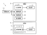
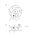
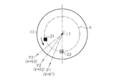
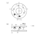
- the electrical block diagram of a rotation connector Explanatory drawing which shows the relationship between the binary value of communication data, and light irradiation timing. It is a figure of the rotation connector which shows the drive timing of the light emitting element at the time of low speed rotation, (a) is a top view, (b) is a side view. Explanatory drawing which shows switching of the drive start point of a light emitting element. It is a figure of the rotation connector which shows the drive timing of the light emitting element at the time of high speed rotation, (a) is a top view, (b) is a side view.
- a vehicular rotary connector 1 is attached between a vehicle body 2 on a fixed side and a steering shaft 3 on a rotating side.
- the rotary connector 1 uses communication between the vehicle body 2 and the steering shaft 3 as non-contact communication, and maintains communication between these two members even when the steering shaft 3 is rotated.
- the rotary connector 1 transmits the output signal Sout of the detection unit 4 provided on the steering wheel (not shown) to the controller 5 on the vehicle body 2 side.
- the controller 5 includes an ECU (Electronic Control Unit) that manages the operation of the rotary connector 1, and determines the detection state of the detection unit 4 based on the output signal Sout.
- ECU Electronic Control Unit
- the detection unit 4 includes, for example, a switch and a sensor disposed on the steering wheel.
- the output signal Sout is not limited to an on / off signal detected by, for example, a switch or a sensor, but may be a data signal detected by sensors such as an image sensor.
- the rotary connector 1 includes a fixed body 8 attached and fixed to the vehicle body 2 and a rotating body 9 that rotates with respect to the fixed body 8. Both the fixed body 8 and the rotating body 9 have a substantially disc shape and are disposed on the same axis (axis L1).
- the axis L1 is the rotational axis of the steering shaft 3.
- the fixed body 8 includes a substrate 12 on which electrical components on the fixed body 8 side are mounted.
- the steering shaft 3 is rotatably inserted through insertion holes 13 and 14 formed at the centers of the fixed body 8 and the substrate 12.
- the rotating body 9 includes a substrate 15 on which electrical components on the rotating body 9 side are mounted.
- the steering shaft 3 is inserted into the insertion holes 16 and 17 formed at the centers of the rotating body 9 and the substrate 15 so that they can be integrally rotated.
- the rotating body 9 is supported by the fixed body 8 and rotates integrally with the steering shaft 3 around the axis L1 (in the direction of arrow R in FIG. 1).
- the vehicle includes an angle detection unit 18 that detects an angle when the rotating body 9 rotates.
- the angle detection unit 18 includes, for example, an optical sensor or a magnetic sensor, and can detect the angle of the rotating body 9 in the range of 0 ° to 360 °.
- the angle detection unit 18 outputs the detected angle detection signal S ⁇ to the controller 5 or the IC of the rotating body 9.
- the rotary connector 1 adopts an optical communication type communication method in which a signal communicated between the fixed body 8 and the rotating body 9 is notified to the other party through the presence or absence of light.
- the optical communication type communication method of this example is a method of wirelessly transmitting the output signal Sout of the detection unit 4 on the steering wheel side as communication data Sd from the rotating body 9 side to the fixed body 8 side through optical communication.
- the communication data Sd constructs binarized information composed of data groups of “0” and “1” by combining light “present” and “absent”. Further, the communication data Sd is preferably a multiplexed signal in which signals output from the plurality of detection units 4 are collected in a time division manner and transmitted to the other party. In optical communication, communication data Sd can be communicated to the other party at high speed (high-speed communication).
- the rotary connector 1 includes a plurality of light emitting elements 21 that project light in optical communication, and a light receiving element 22 that receives light from the light emitting elements 21.
- the light emitting elements 21 are attached to the back surface of the substrate 15 and are arranged at equal intervals around the axis L1 of the rotating body 9.
- the light emitting element 21 is preferably an LED, for example.
- the reason for providing a plurality of light emitting elements 21 is to allow the light from the light emitting elements 21 to reach the light receiving elements 22 regardless of the rotation angle of the rotating body 9.
- the light receiving element 22 is attached to the surface of the substrate 12 and is disposed at a position facing the movement path (movement locus) K (see FIGS. 4 and 6) of the light emitting element 21 when the rotating body 9 rotates. Yes.
- the rotary connector 1 includes an output processing unit 25 that controls the operation of the light emitting element 21.
- the output processing unit 25 is preferably an IC provided on the rotating body 9 and mounted on the substrate 15, for example.
- the output processing unit 25 generates a light emission pattern in accordance with the binarized information of the communication data Sd from the light emitting element 21 by switching processing (lighting on / off) of driving or not driving the light emitting element 21. Then, the light receiving element 22 receives the light of this light emission pattern.
- the rotary connector 1 includes a signal processing unit 26 that acquires communication data Sd from the transmission side (in this example, the output signal Sout of the detection unit 4) based on the light reception signal Sr of the light receiving element 22.
- the signal processing unit 26 is provided in the controller 5.
- the signal processing unit 26 determines the data content of the communication data Sd based on the light reception signal Sr input from the light receiving element 22, and executes an operation according to the communication data Sd.
- the rotary connector 1 has an element drive selection function for selecting and driving only a part of the light emitting elements 21 corresponding to the rotational speed V of the rotating body 9 among the plurality of light emitting elements 21. This is because, if all of the plurality of light emitting elements 21 are always driven, the power for driving the light emitting elements 21 increases and power saving cannot be achieved. Therefore, the light emitting elements 21 are selected by the element driving selection function of this example. To achieve power saving.
- the rotary connector 1 includes a speed determination unit 29 that determines the rotational speed V of the rotating body 9.
- the speed determination unit 29 is provided in the rotating body 9 (IC of the rotating body 9), and determines the rotation speed V of the rotating body 9 based on the angle detection signal S ⁇ input from the angle detection unit 18.
- the rotary connector 1 includes an angle determination unit 30 that determines the rotation angle ⁇ of the rotating body 9.
- the angle determination unit 30 is provided in the rotating body 9 (IC of the rotating body 9), and determines the rotation angle ⁇ (rotation position) of the rotating body 9 based on the angle detection signal S ⁇ input from the angle detection unit 18. It is preferable that the angle determination unit 30 can detect the rotation angle ⁇ of the rotating body 9 with a resolution of several degrees, for example.
- the rotary connector 1 includes an element selection unit 31 that selects a plurality of light emitting elements 21 to be driven based on the determination result of the speed determination unit 29.
- the element selection unit 31 is provided in the rotating body 9 (IC of the rotating body 9), and selects the light emitting element 21 to be driven among the plurality of light emitting elements 21 based on the determination result of the speed determining unit 29.
- the element selection unit 31 of this example selects the light emitting element 21 to be driven according to the rotation angle ⁇ and the rotation speed V of the rotating body 9 based on the determination results of both the speed determination unit 29 and the angle determination unit 30. .
- the output processing unit 25 when various operations are detected by the detection unit 4 in the steering wheel, the output processing unit 25 outputs the communication data Sd having a binary code corresponding to the output signal Sout input from the detection unit 4. Then, it transmits to the fixed body 8 side through optical communication.
- the output processing unit 25 turns on the light emitting element 21 when outputting the binary information equivalent to “1”, and outputs the light emitting element 21 when outputting the binary information equivalent to “0”. Turn off the light.
- the output processing unit 25 constructs the communication data Sd of the binarized information by turning on / off the light emitting element 21 and transmits it to the fixed body 8 side.
- the element selection unit 31 emits light to the drive start point P set on the movement path K according to the rotation speed V of the rotating body 9 when the rotating body 9 rotates.
- the driving start point P is the rotation angle ⁇ of the light emitting element 21 with respect to the light receiving element 22. Note that the rotation angle ⁇ in this example moves away from this point, with the position of the light receiving element 22 in the rotation direction of the rotating body 9 (the direction of arrow R in FIG. 1) as the angle measurement start point (FIG. 4A). It is assumed that the angle increases from “0 °” to “360 °” as it rotates in the counterclockwise direction.
- the light emitting element 21 sets the drive start point P corresponding to the rotational speed V of the rotating body 9, and the light emitting element 21 is positioned at the rotation angle ⁇ obtained by the angle determination unit 30. At this timing, the light emitting element 21 is driven. The light emitting elements 21 that have reached the driving start point P are sequentially driven.
- the range in which the light emitting element 21 is driven in the rotation direction of the rotating body 9 is a drive range (lighting range) E
- the drive range E is widened when the rotation speed V is high. If the rotational speed V is slow, the drive range E is set to be narrow.
- the drive range E is set so that the light receiving element 22 is positioned within the drive range E.
- the light emitting element 21 that is in a driving state, that is, a lighting state, is stopped or turned off by the element selection unit 31 when it is separated from the light receiving element 22 by a predetermined amount (for example, an angle formed by the light receiving element 22 is about 45 °). Is preferred.
- the drive start point P is set on the movement path K at a point corresponding to the rotational speed V of the rotating body 9.
- the rotational speed V is a relatively low speed “V1”
- the point is set at a point “P1” near the light receiving element 22, and when the rotational speed V is “V2” faster than the speed V1, It is set at a point “P2” farther from the light receiving element 22 than the point “P1”.
- the rotation speed V is “V3” which is faster than the speed V2, it is set to a point “P3” far away from the light receiving element 22.
- the drive start timing of the light emitting element 21 is advanced as the rotational speed V of the rotating body 9 increases.
- the driving range (lighting range) E set once in the light emitting element 21, that is, the turn-off timing is not changed. This is because the process becomes complicated if the light-off timing of the light-emitting element 21 is variable according to the speed change.
- the rotational speed V of the rotating body 9 is obtained, and the rotational speed V is determined according to the rotational speed V.
- the light emitting element 21 is driven at the same timing.
- the optical communication not all of the plurality of light emitting elements 21 are always driven, but an appropriate one corresponding to the rotation speed V of the rotating body 9 is selectively driven. Therefore, in the optical communication type rotary connector 1, it is possible to save power by suppressing power consumption.
- the element selection unit 31 selects the light emitting element 21 to be driven using the rotation speed V and the rotation angle ⁇ as parameters. That is, the rotation speed V and the rotation angle ⁇ of the rotating body 9 are obtained using the angle detection signal S ⁇ of the angle detection unit 18, and the light emitting element 21 to be driven is selected according to the rotation speed V and the rotation angle ⁇ .
- the timing at which the light emitting element 21 emits light is determined while viewing not only the rotation speed V but also the rotation angle ⁇ . Therefore, it becomes possible to drive the light emitting element 21 at an optimum timing according to the situation, which is advantageous for improving the stability of communication establishment.
- the element selection unit 31 emits light at the timing when the rotation angle ⁇ becomes the driving start point P, where the angle formed by the light emitting element 21 in the rotation direction of the rotating body 9 (the direction of arrow R in FIG. 1) is the rotation angle ⁇ .
- the element 21 is driven. And the drive timing of the light emitting element 21 is changed by switching the drive start point P according to the rotational speed V. FIG.
- the driving of the light emitting element 21 can be optimized through a simple process of changing the driving start point P of the light emitting element 21 according to the rotation speed V of the rotating body 9. Therefore, it is further advantageous to improve the stability of communication establishment.
- the element selection unit 31 widens the drive range E when the rotation speed V is high. If the rotational speed V is slow, the drive range E is set to be narrowed. Therefore, if the rotational speed V of the rotating body 9 is increased, the driving range E of the light emitting element 21 is set wider accordingly, so that even if the rotating body 9 rotates faster, the light of the light emitting element 21 is emitted. It can be reliably applied to the light receiving element 22.
- the binarization information may be, for example, “0” when the light is turned on and “1” when the light is turned off.
- the light emitting element 21 may be provided on the fixed body 8 and the light receiving element 22 may be provided on the rotating body 9. -The arrangement of the light emitting elements 21 is not limited to the equidistant arrangement, and may be arranged in any way. -The light emitting element 21 can apply members other than LED.
- the light emitting element 21 and the light receiving element 22 are not limited to being provided on the substrates 12 and 15, but may be disposed on the fixed body 8 or the rotating body 9.
- the angle determination unit 30 is not limited to using the angle detection unit 18 such as a steering angle sensor, and may be any member that can detect the amount of rotation of the rotating body 9.
- the driving timing of the light emitting element 21 may be set using only the rotation speed V as a parameter. In this case, for example, when the rotational speed V is fast, the driving of the light emitting elements 21 is sequentially switched at short time intervals, and when the rotational speed V is slow, the driving of the light emitting elements 21 is sequentially switched at long time intervals. Like that.
- the communication data Sd is not limited to a multiplexed signal, and may be data constructed only from the output of one detection unit 4.
- the light amount of the light emitting element 21 may be changed according to the rotation speed V of the rotating body 9.
- the rotation speed V of the rotating body 9 includes acceleration.
- the rotation connector 1 is not limited to being applied to a vehicle, You may use it for another apparatus and apparatus.
Landscapes
- Physics & Mathematics (AREA)
- Engineering & Computer Science (AREA)
- Electromagnetism (AREA)
- Computer Networks & Wireless Communication (AREA)
- Signal Processing (AREA)
- Mechanical Engineering (AREA)
- General Physics & Mathematics (AREA)
- Optics & Photonics (AREA)
- Optical Communication System (AREA)
- Arrangements For Transmission Of Measured Signals (AREA)
Abstract
回転コネクタ(1)は、固定体(8)及び回動体(9)の一方に設けられた複数の発光素子(21)と、他方に設けられた受光素子(22)とを含み、回動体の回動を許容した状態下において固定体と回動体との間での光通信を可能にする。回転コネクタ(1)は、回動体(9)の回転速度(V)を判定する速度判定部(29)と、速度判定部(29)の判定結果を基に、複数の前記発光素子(21)のうち駆動する発光素子を選択する素子選択部(31)とをさらに備える。
Description
本発明は、固定体及び回動体の間の通信を向上する回転コネクタに関する。
従来、一方が他方に対して回転する2部品の間の電気的な通電を維持する回転コネクタとして、ステアリングロールコネクタが広く知られている。この種のステアリングロールコネクタには、例えば光通信を通じて非接触で通信データを回動体から固定体に送信するものが周知である(特許文献1等参照)。
しかし、特許文献1は、複数設けた発光素子を同時に駆動し続ける技術であるので、消費電流が大きく、省電力化に支障を来していた。
本発明の目的は、消費電力を抑制して省電力化することができる回転コネクタを提供することにある。
本発明の目的は、消費電力を抑制して省電力化することができる回転コネクタを提供することにある。
一態様の回転コネクタは、固定体及び回動体の一方に複数の発光素子を設け、これらの他方に受光素子を設けて、前記発光素子及び前記受光素子の間で光通信を可能とすることにより、前記回動体の回動を許容した状態下においての前記固定体及び前記回動体の通信を可能にする構成において、前記回動体の回転速度を判定する速度判定部と、前記速度判定部の判定結果を基に、複数の前記発光素子のうち駆動する当該発光素子を選択する素子選択部とを備えた。
本構成によれば、発光素子及び受光素子を用いた光通信を通じて固定体及び回動体の間の通信を行うにあたり、回動体の回転速度を求め、回転速度に応じたタイミングで発光素子を駆動させる。このように、光通信において、複数設けられた発光素子の全てを常時駆動させるのではなく、回動体の回転速度に応じた適切なものを選択駆動させる。よって、消費電力を抑制して省電力化することが可能となる。
前記回転コネクタにおいて、前記回動体の回転角を判定する角度判定部を備え、前記素子選択部は、前記回転速度及び前記回転角をパラメータとして、駆動させる前記発光素子を選択することが好ましい。この構成によれば、発光素子の駆動を状況に応じた最適なタイミングで行うことが可能となるので、通信成立の安定性を向上するのに有利となる。
前記回転コネクタにおいて、前記素子選択部は、前記回動体の回動方向において前記発光素子が成す角を前記回転角とすると、当該回転角が駆動開始点となったタイミングで前記発光素子を駆動させ、前記回転速度に応じて前記駆動開始点を切り替えることにより、前記発光素子の駆動タイミングを変更することが好ましい。この構成によれば、発光素子の駆動開始点を回動体の回転速度に応じて変化させるという簡素な処理を通じて、発光素子の駆動の最適化が可能となる。よって、通信成立の安定性を向上するのに一層有利となる。
前記回転コネクタにおいて、前記素子選択部は、前記回動体の回動方向において前記発光素子を駆動させる範囲を駆動範囲とすると、前記回転速度が速ければ前記駆動範囲を広くするように設定し、前記回転速度が遅ければ当該駆動範囲を狭くするように設定することが好ましい。この構成によれば、回動体の回転速度が速くなれば、その分、発光素子の駆動範囲が広く設定されるので、回動体が速く回転する場合であっても、発光素子の光を確実に受光素子に当てることが可能となる。
前記回転コネクタにおいて、前記複数の発光素子のうち同時に駆動される前記発光素子の最大数が2つであることが好ましい。この構成によれば、発光素子の全ての常時駆動させる場合に比べて省電力化を図ることができる。
本発明によれば、消費電力を抑制して省電力化することができる。
以下、回転コネクタの一実施形態を図1~図6に従って説明する。
図1に示すように、車両用の回転コネクタ1は、固定側となる車体2と回動側となるステアリングシャフト3との間に取り付けられている。回転コネクタ1は、車体2及びステアリングシャフト3の間の通信を非接触通信として、これら2者間の通信をステアリングシャフト3が回動されても維持するものである。回転コネクタ1は、ステアリングホイール(図示略)に設けられた検知部4の出力信号Soutを、車体2側のコントローラ5に送信する。コントローラ5は、回転コネクタ1の作動を管理するECU(Electronic Control Unit)からなり、出力信号Soutを基に検知部4の検知状態を判断する。
図1に示すように、車両用の回転コネクタ1は、固定側となる車体2と回動側となるステアリングシャフト3との間に取り付けられている。回転コネクタ1は、車体2及びステアリングシャフト3の間の通信を非接触通信として、これら2者間の通信をステアリングシャフト3が回動されても維持するものである。回転コネクタ1は、ステアリングホイール(図示略)に設けられた検知部4の出力信号Soutを、車体2側のコントローラ5に送信する。コントローラ5は、回転コネクタ1の作動を管理するECU(Electronic Control Unit)からなり、出力信号Soutを基に検知部4の検知状態を判断する。
検知部4は、例えばステアリングホイールに配設されたスイッチやセンサ等からなる。また、出力信号Soutは、例えばスイッチやセンサにより検出されたオンオフ信号に限らず、例えば画像センサ等のセンサ類が検出したデータ信号でもよい。
回転コネクタ1は、車体2に取り付け固定される固定体8と、固定体8に対して回動する回動体9とを備える。固定体8及び回動体9は、ともに略円板形状をなし、同一軸心(軸L1)上に配置されている。軸L1は、ステアリングシャフト3の回動軸心である。
固定体8は、固定体8側の電装品が実装される基板12を備える。ステアリングシャフト3は、固定体8及び基板12の各々の中心に形成された挿通孔13,14に回動可能に挿通されている。回動体9は、回動体9側の電装品が実装される基板15を備える。回動体9及び基板15の各々の中心に形成された挿通孔16,17には、ステアリングシャフト3が挿通されて、これらが一体回動可能となっている。ステアリングシャフト3が回動操作されたとき、回動体9は、固定体8に支持されてステアリングシャフト3と軸L1回り(図1の矢印R方向)に一体回動する。
車両は、回動体9が回動したときの角度を検出する角度検出部18を備える。角度検出部18は、例えば光センサや磁気センサからなり、回動体9の角度を0°~360°の範囲で検出可能である。角度検出部18は、検出した角度検出信号Sθをコントローラ5や回動体9のIC等に出力する。
回転コネクタ1は、固定体8及び回動体9の間で通信する信号を、光の有無を通じて相手側に通知する光通信型の通信方式をとる。本例の光通信型の通信方式は、ステアリングホイール側の検知部4の出力信号Soutを、光通信を通じて、通信データSdとして回動体9側から固定体8側に無線送信する方式である。通信データSdは、光の「有り」及び「無し」の組み合わせにより、「0」及び「1」のデータ群からなる2値化情報を構築する。また、通信データSdは、複数の検知部4から出力される信号を時分割によりまとめて相手側に送信する多重信号であることが好ましい。光通信は、通信データSdを高速で相手側に通信すること(高速通信)が可能である。
回転コネクタ1は、光通信において光を投光する複数の発光素子21と、発光素子21の光を受光する受光素子22とを備える。発光素子21は、基板15の裏面に取り付けられるとともに、回動体9の軸L1回りに沿って等間隔に配置されている。発光素子21は、例えばLEDであることが好ましい。発光素子21を複数設けるのは、回動体9がどの回転角にあっても、発光素子21の光を受光素子22に届かせるためである。受光素子22は、基板12の表面に取り付けられるとともに、回動体9が回動するときの発光素子21の移動経路(移動軌跡)K(図4及び図6参照)と対向する位置に配置されている。
図2に示すように、回転コネクタ1は、発光素子21の作動を制御する出力処理部25を備える。出力処理部25は、回動体9に設けられ、例えば基板15に実装されたICであることが好ましい。出力処理部25は、発光素子21を駆動させる、又は駆動させないという処理(光の点灯/消灯)を切り替えることにより、発光素子21から通信データSdの2値化情報に準じた発光パターンを生成させ、この発光パターンの光を受光素子22に受光させる。
回転コネクタ1は、受光素子22の受光信号Srを基に送信側からの通信データSd(本例は検知部4の出力信号Sout)を取得する信号処理部26を備える。信号処理部26は、コントローラ5に設けられている。信号処理部26は、受光素子22から入力する受光信号Srを基に通信データSdのデータ内容を判断し、この通信データSdに応じた作動を実行する。
回転コネクタ1は、複数の発光素子21のうち回動体9の回転速度Vに応じた一部の発光素子21のみ選択して駆動させる素子駆動選択機能を備える。これは、仮に複数の発光素子21を全て常時駆動させると、発光素子21の駆動に係る電力が増えて省電力化することができないため、本例の素子駆動選択機能により、発光素子21を選択的に駆動して省電力化を実現する。
回転コネクタ1は、回動体9の回転速度Vを判定する速度判定部29を備える。速度判定部29は、回動体9(回動体9のIC)に設けられ、角度検出部18から入力する角度検出信号Sθを基に回動体9の回転速度Vを判定する。
回転コネクタ1は、回動体9の回転角θを判定する角度判定部30を備える。角度判定部30は、回動体9(回動体9のIC)に設けられ、角度検出部18から入力する角度検出信号Sθを基に回動体9の回転角θ(回転位置)を判定する。角度判定部30は、例えば数度の分解能で回動体9の回転角θを検出できることが好ましい。
回転コネクタ1は、速度判定部29の判定結果を基に複数の発光素子21のうち駆動させるものを選択する素子選択部31を備える。素子選択部31は、回動体9(回動体9のIC)に設けられ、速度判定部29の判定結果を基に複数の発光素子21のうち駆動する発光素子21を選択する。本例の素子選択部31は、速度判定部29及び角度判定部30の両方の判定結果を基に、回動体9の回転角θ及び回転速度Vに応じて、駆動する発光素子21を選択する。
次に、図3~図6を用いて、回転コネクタ1の作用及び効果を説明する。
図3に示すように、例えばステアリングホイールにおいて検知部4で種々の操作が検出されたとき、出力処理部25は、検知部4から入力する出力信号Soutに応じた2値符号の通信データSdを、光通信を通じて固定体8側に送信する。本例の場合、出力処理部25は、例えば2値化情報の「1」相当を出力するとき、発光素子21を点灯させ、2値化情報の「0」相当を出力するとき、発光素子21を消灯させる。このように、出力処理部25は、発光素子21の点灯/消灯により2値化情報の通信データSdを構築して、固定体8側に送信する。
図3に示すように、例えばステアリングホイールにおいて検知部4で種々の操作が検出されたとき、出力処理部25は、検知部4から入力する出力信号Soutに応じた2値符号の通信データSdを、光通信を通じて固定体8側に送信する。本例の場合、出力処理部25は、例えば2値化情報の「1」相当を出力するとき、発光素子21を点灯させ、2値化情報の「0」相当を出力するとき、発光素子21を消灯させる。このように、出力処理部25は、発光素子21の点灯/消灯により2値化情報の通信データSdを構築して、固定体8側に送信する。
図4(a),(b)に示すように、素子選択部31は、回動体9の回転時、回動体9の回転速度Vに応じて移動経路K上に設定した駆動開始点Pに発光素子21が到達したとき、そのタイミングにおいて発光素子21を駆動させる。駆動開始点Pは、受光素子22を基準とした発光素子21の回転角θである。なお、本例の回転角θは、回動体9の回動方向(図1の矢印R方向)における受光素子22の位置を角度計測開始点として、この点から離れていく(図4(a)中の反時計回り方向に回動する)に従って角度が「0°」から増加して「360°」まで変化する値をとるとする。
このように、回動体9の回転時、発光素子21は、回動体9の回転速度Vに応じた駆動開始点Pを設定し、角度判定部30により求めた回転角θに発光素子21が位置したタイミングで、発光素子21を駆動させる。そして、発光素子21は、駆動開始点Pに到達したものが順番に駆動されていく。このように、回動体9の回動方向(図1の矢印R方向)において発光素子21を駆動させる範囲を駆動範囲(点灯範囲)Eとすると、回転速度Vが速ければ駆動範囲Eを広くするように設定し、回転速度Vが遅ければ駆動範囲Eを狭くするように設定する。駆動範囲Eは、受光素子22が駆動範囲E内に位置するように設定される。なお、駆動状態すなわち点灯状態となった発光素子21は、受光素子22から所定量(例えば受光素子22との成す角が45°程度)離れたときに素子選択部31によって駆動停止すなわち消灯することが好ましい。
図5に示すように、駆動開始点Pは、移動経路K上において、回動体9の回転速度Vに応じた地点に設定される。具体的には、回転速度Vが相対的に低い速度「V1」のときは、受光素子22寄りの地点「P1」に設定され、回転速度Vが速度V1よりも速い「V2」のときは、地点「P1」よりも受光素子22から離れた地点「P2」に設定される。また、回転速度Vが速度V2よりも速い「V3」のときは、受光素子22から大きく離れた地点「P3」に設定される。このように、回動体9の回転速度Vが速くなるに連れ、発光素子21の駆動開始タイミングが早められる。
よって、図5に示すように、回動体9が高速で回転するときは、駆動開始点Pが受光素子22から遠めの位置に設定される。このため、図6(a),(b)に示すように、回動体9の高速回動時、受光素子22に最も近い発光素子21aのみならず、1つ手前の発光素子21bも先行して駆動状態に切り替えられる。すなわち、複数の発光素子21が同時駆動される。これにより、発光素子21の光が途切れ難くなり、光通信の安定性が向上される。
なお、回動体9の回転速度が仮に途中で変化しても、発光素子21において1度設定された駆動範囲(点灯範囲)E、すなわち消灯タイミングは変更されないようにすることが好ましい。これは、速度変化に応じて発光素子21の消灯タイミングも可変とすると、処理が煩雑になるからである。
さて、本例の場合、発光素子21及び受光素子22を用いた光通信を通じて固定体8及び回動体9の間の通信を行うにあたり、回動体9の回転速度Vを求め、回転速度Vに応じたタイミングで発光素子21を駆動させる。このように、光通信において、複数設けられた発光素子21の全てを常時駆動させるのではなく、回動体9の回転速度Vに応じた適切なものを選択駆動させる。よって、光通信型の回転コネクタ1において、消費電力を抑制して省電力化することができる。
素子選択部31は、回転速度V及び回転角θをパラメータとして、駆動させる発光素子21を選択する。すなわち、角度検出部18の角度検出信号Sθを用いて回動体9の回転速度V及び回転角θを求め、回転速度V及び回転角θに応じて、駆動する発光素子21を選択する。このように、本例の場合は、回転速度Vのみならず、回転角θも見ながら、発光素子21をどのタイミングで発光させるのかを決める。よって、発光素子21の駆動を状況に応じた最適なタイミングで行うことが可能となるので、通信成立の安定性を向上するのに有利となる。
素子選択部31は、回動体9の回動方向(図1の矢印R方向)において発光素子21が成す角を回転角θとすると、この回転角θが駆動開始点Pとなったタイミングで発光素子21を駆動させる。そして、回転速度Vに応じて駆動開始点Pを切り替えることにより、発光素子21の駆動タイミングを変更する。このため、発光素子21の駆動開始点Pを回動体9の回転速度Vに応じて変化させるという簡素な処理を通じて、発光素子21の駆動の最適化が可能となる。よって、通信成立の安定性を向上するのに一層有利となる。
素子選択部31は、回動体9の回動方向(図1の矢印R方向)において発光素子21を駆動させる範囲を駆動範囲Eとすると、回転速度Vが速ければ駆動範囲Eを広くするように設定し、回転速度Vが遅ければ駆動範囲Eを狭くするように設定する。よって、回動体9の回転速度Vが速くなれば、その分、発光素子21の駆動範囲Eが広く設定されるので、回動体9が速く回転する場合であっても、発光素子21の光を確実に受光素子22に当てることができる。
なお、実施形態はこれまでに述べた構成に限らず、以下の態様に変更してもよい。
・2値化情報は、例えば光が点灯されているときを「0」とし、光が消灯されているときを「1」としてもよい。
・2値化情報は、例えば光が点灯されているときを「0」とし、光が消灯されているときを「1」としてもよい。
・発光素子21を固定体8に設け、受光素子22を回動体9に設けてもよい。
・発光素子21の配置の仕方は、等間隔配置に限定されず、どのように並べてもよい。
・発光素子21は、LED以外の他の部材を適用可能である。
・発光素子21の配置の仕方は、等間隔配置に限定されず、どのように並べてもよい。
・発光素子21は、LED以外の他の部材を適用可能である。
・発光素子21及び受光素子22は、基板12,15上に設けられることに限らず、固定体8や回動体9に配置されていればよい。
・角度判定部30は、ステアリングアングルセンサ等の角度検出部18を用いることに限らず、回動体9の回転量を検出できる部材であればよい。
・角度判定部30は、ステアリングアングルセンサ等の角度検出部18を用いることに限らず、回動体9の回転量を検出できる部材であればよい。
・発光素子21を選択駆動させるにあたり、どの発光素子21を点灯させるのは、実施形態以外のパターンに変更可能である。
・光通信による経路は、データ線を実現することに限らず、例えば制御線やパワー線であってもよい。
・光通信による経路は、データ線を実現することに限らず、例えば制御線やパワー線であってもよい。
・回転速度Vのみをパラメータとして、発光素子21の駆動タイミングを設定してもよい。この場合は、例えば回転速度Vが速いとき、短い時間間隔で発光素子21の駆動を順次切り替えていくようにし、回転速度Vが遅いとき、長い時間間隔で発光素子21の駆動を順次切り替えていくようにする。
・通信データSdは、多重信号に限定されず、1つの検知部4の出力のみから構築されるデータでもよい。
・回動体9の回転速度Vに応じて、発光素子21の光量を変化させてもよい。
・回動体9の回転速度Vに応じて、発光素子21の光量を変化させてもよい。
・回動体9の回転速度Vは、加速度を含むものとする。
・回転コネクタ1は、車両に適用されることに限定されず、他の機器や装置に使用してもよい。
・回転コネクタ1は、車両に適用されることに限定されず、他の機器や装置に使用してもよい。
Claims (5)
- 固定体及び回動体の一方に複数の発光素子を設け、これらの他方に受光素子を設けて、前記発光素子及び前記受光素子の間で光通信を可能とすることにより、前記回動体の回動を許容した状態下においての前記固定体及び前記回動体の通信を可能にする回転コネクタにおいて、
前記回動体の回転速度を判定する速度判定部と、
前記速度判定部の判定結果を基に、複数の前記発光素子のうち駆動する当該発光素子を選択する素子選択部と
を備えたことを特徴とする回転コネクタ。 - 前記回動体の回転角を判定する角度判定部を備え、
前記素子選択部は、前記回転速度及び前記回転角をパラメータとして、駆動させる前記発光素子を選択する
請求項1に記載の回転コネクタ。 - 前記素子選択部は、前記回動体の回動方向において前記発光素子が成す角を前記回転角とすると、当該回転角が駆動開始点となったタイミングで前記発光素子を駆動させ、前記回転速度に応じて前記駆動開始点を切り替えることにより、前記発光素子の駆動タイミングを変更する
請求項2に記載の回転コネクタ。 - 前記素子選択部は、前記回動体の回動方向において前記発光素子を駆動させる範囲を駆動範囲とすると、前記回転速度が速ければ前記駆動範囲を広くするように設定し、前記回転速度が遅ければ当該駆動範囲を狭くするように設定する
請求項2又は3に記載の回転コネクタ。 - 前記複数の発光素子のうち同時に駆動される前記発光素子の最大数が2つである
請求項1~4のうちのいずれか一項に記載の回転コネクタ。
Priority Applications (3)
| Application Number | Priority Date | Filing Date | Title |
|---|---|---|---|
| US16/316,187 US20200247335A1 (en) | 2016-07-11 | 2017-06-26 | Rotary connector |
| CN201780037319.3A CN109313844A (zh) | 2016-07-11 | 2017-06-26 | 旋转连接器 |
| DE112017003493.0T DE112017003493T8 (de) | 2016-07-11 | 2017-06-26 | Drehverbinder |
Applications Claiming Priority (2)
| Application Number | Priority Date | Filing Date | Title |
|---|---|---|---|
| JP2016136908A JP6684671B2 (ja) | 2016-07-11 | 2016-07-11 | 回転コネクタ |
| JP2016-136908 | 2016-07-11 |
Publications (1)
| Publication Number | Publication Date |
|---|---|
| WO2018012271A1 true WO2018012271A1 (ja) | 2018-01-18 |
Family
ID=60952490
Family Applications (1)
| Application Number | Title | Priority Date | Filing Date |
|---|---|---|---|
| PCT/JP2017/023457 Ceased WO2018012271A1 (ja) | 2016-07-11 | 2017-06-26 | 回転コネクタ |
Country Status (5)
| Country | Link |
|---|---|
| US (1) | US20200247335A1 (ja) |
| JP (1) | JP6684671B2 (ja) |
| CN (1) | CN109313844A (ja) |
| DE (1) | DE112017003493T8 (ja) |
| WO (1) | WO2018012271A1 (ja) |
Cited By (1)
| Publication number | Priority date | Publication date | Assignee | Title |
|---|---|---|---|---|
| DE102018126023A1 (de) * | 2018-10-19 | 2020-04-23 | Valeo Schalter Und Sensoren Gmbh | Übertragungsvorrichtung, Lenksäulenanordnung, Fahrzeug und Verfahren zum Betrieb einer Übertragungsvorrichtung |
Families Citing this family (1)
| Publication number | Priority date | Publication date | Assignee | Title |
|---|---|---|---|---|
| US11921326B2 (en) * | 2021-04-06 | 2024-03-05 | Sanmina Corporation | Open-axis optical rotary joint |
Citations (3)
| Publication number | Priority date | Publication date | Assignee | Title |
|---|---|---|---|---|
| JPH0213143A (ja) * | 1988-06-30 | 1990-01-17 | Hokuriyou Denko Kk | 光データ伝送装置 |
| JP2000082998A (ja) * | 1992-01-14 | 2000-03-21 | Toshiba Corp | デ―タ伝送装置 |
| JP2009147942A (ja) * | 2007-12-17 | 2009-07-02 | Siemens Ag | 光信号の伝送装置および方法 |
Family Cites Families (6)
| Publication number | Priority date | Publication date | Assignee | Title |
|---|---|---|---|---|
| JPS59188799A (ja) | 1983-04-11 | 1984-10-26 | 矢崎総業株式会社 | 車両用多重信号伝送装置 |
| DE3411121A1 (de) * | 1984-03-26 | 1985-10-03 | Schleifring und Apparatebau GmbH, 8080 Fürstenfeldbruck | Vorrichtung zur uebertragung von lichtsignalen zwischen zwei bauteilen |
| JP3643384B2 (ja) * | 1992-01-14 | 2005-04-27 | 株式会社東芝 | X線断層撮影装置 |
| KR100493595B1 (ko) * | 2002-10-29 | 2005-06-10 | 주식회사 에이티아이 | 초고속 데이터 전송을 위한 티오 팩키지 |
| JP4080503B2 (ja) * | 2005-10-03 | 2008-04-23 | 中部日本マルコ株式会社 | 非接触コネクタ |
| JP5532231B2 (ja) * | 2010-05-11 | 2014-06-25 | 東芝ライテック株式会社 | 発光装置および照明装置 |
-
2016
- 2016-07-11 JP JP2016136908A patent/JP6684671B2/ja not_active Expired - Fee Related
-
2017
- 2017-06-26 WO PCT/JP2017/023457 patent/WO2018012271A1/ja not_active Ceased
- 2017-06-26 US US16/316,187 patent/US20200247335A1/en not_active Abandoned
- 2017-06-26 CN CN201780037319.3A patent/CN109313844A/zh active Pending
- 2017-06-26 DE DE112017003493.0T patent/DE112017003493T8/de not_active Expired - Fee Related
Patent Citations (3)
| Publication number | Priority date | Publication date | Assignee | Title |
|---|---|---|---|---|
| JPH0213143A (ja) * | 1988-06-30 | 1990-01-17 | Hokuriyou Denko Kk | 光データ伝送装置 |
| JP2000082998A (ja) * | 1992-01-14 | 2000-03-21 | Toshiba Corp | デ―タ伝送装置 |
| JP2009147942A (ja) * | 2007-12-17 | 2009-07-02 | Siemens Ag | 光信号の伝送装置および方法 |
Cited By (1)
| Publication number | Priority date | Publication date | Assignee | Title |
|---|---|---|---|---|
| DE102018126023A1 (de) * | 2018-10-19 | 2020-04-23 | Valeo Schalter Und Sensoren Gmbh | Übertragungsvorrichtung, Lenksäulenanordnung, Fahrzeug und Verfahren zum Betrieb einer Übertragungsvorrichtung |
Also Published As
| Publication number | Publication date |
|---|---|
| DE112017003493T5 (de) | 2019-04-25 |
| DE112017003493T8 (de) | 2019-07-04 |
| CN109313844A (zh) | 2019-02-05 |
| US20200247335A1 (en) | 2020-08-06 |
| JP6684671B2 (ja) | 2020-04-22 |
| JP2018010357A (ja) | 2018-01-18 |
Similar Documents
| Publication | Publication Date | Title |
|---|---|---|
| KR102152702B1 (ko) | 전자식 변속 장치 | |
| CN104819283B (zh) | 换档档位切换装置 | |
| EP2988060B1 (en) | Vehicle lamp | |
| JP2008012109A5 (ja) | ||
| WO2018012271A1 (ja) | 回転コネクタ | |
| JP4781423B2 (ja) | 光信号の伝送装置および方法 | |
| WO2018012190A1 (ja) | 回転コネクタ | |
| KR20050056207A (ko) | 회전하는 가시 표면상의 정보 시각화 장치 | |
| JP2011238156A5 (ja) | ||
| JP2009147942A6 (ja) | 光信号の伝送装置および方法 | |
| US8989937B2 (en) | Emergency steering system and controlling method of the same | |
| US20110043347A1 (en) | Control method for switching between scales in vehicular instrument, and vehicular instrument | |
| JP2003108248A (ja) | 操作装置 | |
| JP2018013928A (ja) | 回転コネクタ | |
| JP4700632B2 (ja) | 多方向操作装置 | |
| JP2016218063A (ja) | 近接覚センサ | |
| WO2018021017A1 (ja) | 回転コネクタ | |
| JP2018014596A (ja) | 回転コネクタ | |
| KR200338052Y1 (ko) | 라인 트레이서의 모터 제동장치 | |
| JP2016146048A (ja) | 原点位置復帰装置、及び、原点位置復帰方法 | |
| JP5338716B2 (ja) | 車両用ストップランプスイッチ | |
| WO2021017831A1 (zh) | LiFi通信控制控制方法、装置、发送端以及移动终端 | |
| WO2018008357A1 (ja) | 回転コネクタ | |
| JP4487828B2 (ja) | ワイパー制御装置 | |
| TW201934286A (zh) | 開關、個體識別資料發送方法以及個體識別資料發送程式 |
Legal Events
| Date | Code | Title | Description |
|---|---|---|---|
| 121 | Ep: the epo has been informed by wipo that ep was designated in this application |
Ref document number: 17827401 Country of ref document: EP Kind code of ref document: A1 |
|
| 122 | Ep: pct application non-entry in european phase |
Ref document number: 17827401 Country of ref document: EP Kind code of ref document: A1 |