WO2018012198A1 - 光デバイス及び立体表示方法 - Google Patents
光デバイス及び立体表示方法 Download PDFInfo
- Publication number
- WO2018012198A1 WO2018012198A1 PCT/JP2017/022342 JP2017022342W WO2018012198A1 WO 2018012198 A1 WO2018012198 A1 WO 2018012198A1 JP 2017022342 W JP2017022342 W JP 2017022342W WO 2018012198 A1 WO2018012198 A1 WO 2018012198A1
- Authority
- WO
- WIPO (PCT)
- Prior art keywords
- image
- light
- optical path
- surface image
- optical device
- Prior art date
- Legal status (The legal status is an assumption and is not a legal conclusion. Google has not performed a legal analysis and makes no representation as to the accuracy of the status listed.)
- Ceased
Links
Images






Classifications
-
- G—PHYSICS
- G02—OPTICS
- G02B—OPTICAL ELEMENTS, SYSTEMS OR APPARATUS
- G02B30/00—Optical systems or apparatus for producing three-dimensional [3D] effects, e.g. stereoscopic images
- G02B30/40—Optical systems or apparatus for producing three-dimensional [3D] effects, e.g. stereoscopic images giving the observer of a single two-dimensional [2D] image a perception of depth
-
- F—MECHANICAL ENGINEERING; LIGHTING; HEATING; WEAPONS; BLASTING
- F21—LIGHTING
- F21S—NON-PORTABLE LIGHTING DEVICES; SYSTEMS THEREOF; VEHICLE LIGHTING DEVICES SPECIALLY ADAPTED FOR VEHICLE EXTERIORS
- F21S2/00—Systems of lighting devices, not provided for in main groups F21S4/00 - F21S10/00 or F21S19/00, e.g. of modular construction
-
- G—PHYSICS
- G02—OPTICS
- G02B—OPTICAL ELEMENTS, SYSTEMS OR APPARATUS
- G02B30/00—Optical systems or apparatus for producing three-dimensional [3D] effects, e.g. stereoscopic images
- G02B30/50—Optical systems or apparatus for producing three-dimensional [3D] effects, e.g. stereoscopic images the image being built up from image elements distributed over a three-dimensional [3D] volume, e.g. voxels
- G02B30/56—Optical systems or apparatus for producing three-dimensional [3D] effects, e.g. stereoscopic images the image being built up from image elements distributed over a three-dimensional [3D] volume, e.g. voxels by projecting aerial or floating images
-
- G—PHYSICS
- G02—OPTICS
- G02B—OPTICAL ELEMENTS, SYSTEMS OR APPARATUS
- G02B5/00—Optical elements other than lenses
-
- G—PHYSICS
- G02—OPTICS
- G02B—OPTICAL ELEMENTS, SYSTEMS OR APPARATUS
- G02B6/00—Light guides; Structural details of arrangements comprising light guides and other optical elements, e.g. couplings
- G02B6/0001—Light guides; Structural details of arrangements comprising light guides and other optical elements, e.g. couplings specially adapted for lighting devices or systems
- G02B6/0011—Light guides; Structural details of arrangements comprising light guides and other optical elements, e.g. couplings specially adapted for lighting devices or systems the light guides being planar or of plate-like form
- G02B6/0033—Means for improving the coupling-out of light from the light guide
- G02B6/0035—Means for improving the coupling-out of light from the light guide provided on the surface of the light guide or in the bulk of it
-
- G—PHYSICS
- G03—PHOTOGRAPHY; CINEMATOGRAPHY; ANALOGOUS TECHNIQUES USING WAVES OTHER THAN OPTICAL WAVES; ELECTROGRAPHY; HOLOGRAPHY
- G03B—APPARATUS OR ARRANGEMENTS FOR TAKING PHOTOGRAPHS OR FOR PROJECTING OR VIEWING THEM; APPARATUS OR ARRANGEMENTS EMPLOYING ANALOGOUS TECHNIQUES USING WAVES OTHER THAN OPTICAL WAVES; ACCESSORIES THEREFOR
- G03B35/00—Stereoscopic photography
- G03B35/18—Stereoscopic photography by simultaneous viewing
-
- G—PHYSICS
- G09—EDUCATION; CRYPTOGRAPHY; DISPLAY; ADVERTISING; SEALS
- G09F—DISPLAYING; ADVERTISING; SIGNS; LABELS OR NAME-PLATES; SEALS
- G09F13/00—Illuminated signs; Luminous advertising
- G09F13/18—Edge-illuminated signs
-
- G—PHYSICS
- G09—EDUCATION; CRYPTOGRAPHY; DISPLAY; ADVERTISING; SEALS
- G09F—DISPLAYING; ADVERTISING; SIGNS; LABELS OR NAME-PLATES; SEALS
- G09F19/00—Advertising or display means not otherwise provided for
- G09F19/12—Advertising or display means not otherwise provided for using special optical effects
- G09F19/125—Stereoscopic displays; 3D displays
-
- G—PHYSICS
- G02—OPTICS
- G02B—OPTICAL ELEMENTS, SYSTEMS OR APPARATUS
- G02B6/00—Light guides; Structural details of arrangements comprising light guides and other optical elements, e.g. couplings
- G02B6/0001—Light guides; Structural details of arrangements comprising light guides and other optical elements, e.g. couplings specially adapted for lighting devices or systems
- G02B6/0011—Light guides; Structural details of arrangements comprising light guides and other optical elements, e.g. couplings specially adapted for lighting devices or systems the light guides being planar or of plate-like form
- G02B6/0033—Means for improving the coupling-out of light from the light guide
- G02B6/0035—Means for improving the coupling-out of light from the light guide provided on the surface of the light guide or in the bulk of it
- G02B6/0036—2-D arrangement of prisms, protrusions, indentations or roughened surfaces
-
- G—PHYSICS
- G02—OPTICS
- G02B—OPTICAL ELEMENTS, SYSTEMS OR APPARATUS
- G02B6/00—Light guides; Structural details of arrangements comprising light guides and other optical elements, e.g. couplings
- G02B6/0001—Light guides; Structural details of arrangements comprising light guides and other optical elements, e.g. couplings specially adapted for lighting devices or systems
- G02B6/0011—Light guides; Structural details of arrangements comprising light guides and other optical elements, e.g. couplings specially adapted for lighting devices or systems the light guides being planar or of plate-like form
- G02B6/0033—Means for improving the coupling-out of light from the light guide
- G02B6/0058—Means for improving the coupling-out of light from the light guide varying in density, size, shape or depth along the light guide
- G02B6/006—Means for improving the coupling-out of light from the light guide varying in density, size, shape or depth along the light guide to produce indicia, symbols, texts or the like
Definitions
- the present invention relates to an optical device for displaying a stereoscopic image and a stereoscopic display method.
- Patent Document 1 an image display device disclosed in Patent Document 1 is known as an optical device that displays a stereoscopic image.
- the image display device 100 disclosed in Patent Document 1 includes a light guide plate 110, a light source 101 provided at an end of the light guide plate 110, and a back surface of the light guide plate 110, as shown in FIG. Including left eye display patterns 111a, 112a, 113a having a plurality of first prisms formed, and right eye display patterns 111ba, 112b, 113b having a plurality of second prisms formed on the back surface of light guide plate 110.
- the left-eye display pattern 111a forms a two-dimensional surface “A” by a plurality of first prisms P1
- the right-eye display pattern 111b has a plurality of second prisms P2. To form a two-dimensional surface “A”.
- the image for the left eye and the image for the right eye are displayed on the surface side of the light guide plate 110 by reflecting the light from the light source 101 with the plurality of first prisms and the second prism.
- the plane image “A” and the plane image “B” from the back side toward the front side.
- a surface image having a stereoscopic effect in which the observation images 120 are arranged in the order of the surface image “C” can be observed.
- Each observation image 120 is observed as if it emerges at the intersection point on the optical path of the light beam from the left-eye image and the right-eye image, so the larger interval is closer to the observer. Has an intersection and is closer to you. Therefore, the observer can visually recognize a three-dimensional display in a natural state.
- the boundary between the plane image and the space is not clear and it is difficult to feel the stereoscopic effect. is doing.
- the present invention has been made in view of the above-described conventional problems, and an object thereof is to provide an optical device and a stereoscopic display method in which a stereoscopic effect can be easily recognized.
- an optical device includes a surface image imaging unit that emits light so that a surface image having a predetermined shape is formed in space, and an outer edge region of the surface image. And a contour image imaging unit for emitting light so that a contour image having a light intensity different from that of the surface image is formed.
- a surface image having a predetermined shape is formed in a space, and a contour image having a light intensity different from that of the surface image is formed in an outer edge region of the surface image. It is said.
- FIG. 1 shows an embodiment of an optical device according to the present invention, and is a perspective view showing a configuration of the optical device. It is sectional drawing which shows the structure of the said optical device. It is a perspective view which shows the structure for forming the surface image in the said optical device into the surface image in a device. It is a top view which shows the structure for forming the surface image in the said optical device. It is a front view which shows an example of the stereo image which consists of a surface image imaged by the said optical device. It is a perspective view showing an example of a configuration of a prism formed on a light guide plate in an optical device for forming the surface image.
- FIG. 10 is a perspective view showing another modification of the prism formed on the light guide plate in the optical device for forming the surface image, and showing the shape of the prism when forming the surface image as a parallax image.
- FIG. 1 It is a perspective view which shows the structure of the 2nd optical path deflection
- A is a top view which shows the structure of the 2nd optical path deflection part group which forms the line image in the said optical device
- (b) is the 2nd optical path deflection part group which forms the line image in the said optical device.
- It is a top view which shows the structure of a modification.
- FIG. 5 is a diagram illustrating an arrangement example when a surface image is formed using a first optical path deflecting unit group for a surface image and a line image is formed using a first optical path deflecting unit group for a contour image. is there. It is a figure which shows the example of an arrangement
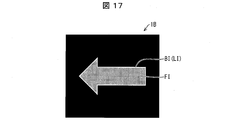
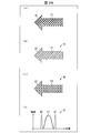
- (A) and (b) are perspective views which show the stereo image which consists of a surface image and an outline image imaged by the said optical device.
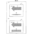
- FIG. 5 is a front view showing an optical device according to a second embodiment of the present invention, and showing a surface image and a contour image formed by the optical device.
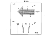
- A shows the modification of the optical device of Embodiment 2 in this invention, Comprising: It is a front view which shows the surface image and outline image which were imaged by the said optical device, (b) is the said optical device. It is a perspective view which shows the surface image and outline image which were imaged by FIG.
- (A) shows the other modification of the optical device of Embodiment 2 in this invention, Comprising: It is a front view which shows the surface image and outline image which were imaged by the said optical device, (b) is the said It is a distribution map which shows the relationship between the light intensity and position of the surface image and outline image which were imaged with the optical device.
- (A) shows the structure by the optical device of the comparative example for showing the optical device of Embodiment 3 in this invention, Comprising: It is a distribution map which shows distribution of the light intensity of the surface image of a design stage, (b ) Is a distribution diagram showing the light intensity of the surface image actually formed by the optical device, and (c) is a front view showing the surface image actually formed by the optical device.
- FIG. 1 It is a perspective view which shows the state which the blur has generate
- (A) is a top view which shows the shape of the prism in a design stage
- (b) is a distribution map which shows the light intensity distribution of the surface image imaged by the said prism.
- (A) (b) is a top view which shows the actually shape
- (c) is a distribution map which shows the light intensity distribution of the surface image imaged by the said prism. .
- FIG. (A) shows the optical device of Embodiment 3 in this invention, Comprising: In the design stage, the outer edge area
- FIG. (A) shows the modification of the optical device of Embodiment 3 in this invention, Comprising: It is a perspective view which shows the condition which improves intensity distribution about both a horizontal direction and a vertical direction, (b) is a horizontal direction.
- FIG. 27A is a perspective view showing a configuration of a prism of the first optical path deflecting unit group of the optical device shown in FIGS. 26A and 26B
- FIG. 26B is a view showing the light shown in FIG.
- FIG. 1 It is a perspective view which shows the structure of the prism of the 1st optical path deflection
- (A) is a front view which shows the surface image of a solid coating
- (b) shows the structure of the optical device of Embodiment 5 in this invention, Comprising: The front which shows the surface image to which the pattern was attached
- (d) is a distribution diagram which shows light intensity distribution when a surface image and a contour image with a pattern are put together.
- (A) and (b) are the front views which show the structure of the optical device of Embodiment 6 in this invention, Comprising: The shadowed surface image is shown.
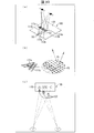
- (A)-(c) is a figure which shows the structure of the image display apparatus as a conventional optical device.
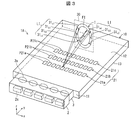
- FIG. 1 is a perspective view showing a configuration of an optical device 1A according to the present embodiment.
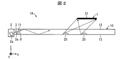
- FIG. 2 is a cross-sectional view showing the configuration of the optical device 1A.
- the optical device 1 ⁇ / b> A guides light incident from the light source 2 and the light source 2 as a surface image imaging unit and a contour image imaging unit, respectively, and emits light from the light emitting surface. 12 and a plurality of light path deflecting units 20 arranged on the light guide plate 10 and configured to form a three-dimensional image I in space by deflecting and guiding the guided light.
- the plurality of optical path deflecting units 20 includes, as the surface image forming unit, a surface image optical path deflecting unit group 21 that forms the surface image FI on the space by deflecting the emitted light and emitting the light.
- a contour image imaging unit includes a contour image optical path deflecting unit group 24 that forms the contour image BI in the space by deflecting the emitted light and emitting the light.
- the light source 2 is composed of a plurality of light emitting diodes (LEDs) 2a, for example.
- the light emitted from each light emitting diode (LED) 2 a is adjusted by the incident light adjusting unit 3 and enters the incident surface 11 of the light guide plate 10.
- the light source 2 is composed of a plurality of light emitting diodes (LEDs) 2a, for example.
- the present invention is not necessarily limited to this, and may be composed of a single light emitting diode (LED) 2a or the like.
- a single light emitting diode (LED) 2 a or the like may be provided on the side surface facing the incident surface 11.
- the incident light adjusting unit 3 includes a plurality of lenses 3a so as to correspond to the light emitting diodes (LEDs) 2a on a one-to-one basis.
- Each lens 3a reduces, enlarges, or does not change the spread of light on the xy plane described later in the direction along the optical axis of the light emitted from the corresponding light emitting diode (LED) 2a.
- the lens 3 a brings the light emitted from the light emitting diode (LED) 2 a close to parallel light, or guides the entire area within the light guide plate 10.
- the spread angle of the light guided by the light guide plate 10 may be 5 ° or less, preferably less than 1 °.
- the incident light adjusting unit 3 includes a mask having an opening smaller than a predetermined width in the x-axis direction. May be.
- the optical axis of the emitted light of the light emitting diode (LED) 2a has an angle ⁇ with respect to the emitting surface 12 described later.
- the angle ⁇ that is a narrow angle formed by the optical axis of the emitted light of the light emitting diode (LED) 2a and the emitting surface 12 is about 20 °.
- the light guide plate 10 is formed of a resin material that is transparent and has a relatively high refractive index.
- a material for forming the light guide plate 10 for example, polycarbonate resin (PC), polymethyl methacrylate resin (PMMA) glass, or the like can be used.
- the light guide plate 10 has an incident surface 11 on which light from the light source 2 is incident, an exit surface 12 that emits light that is the surface of the light guide plate 10, and a back surface 13 on which an optical path deflecting unit 20 is formed. ing.
- the stereoscopic image I is recognized stereoscopically by the observer.
- the stereoscopic image I refers to an image that is recognized to exist at a position different from the exit surface 12 of the light guide plate 10.
- the stereoscopic image I also includes, for example, a two-dimensional image that is recognized at a position away from the emission surface 12 of the light guide plate 10. That is, the stereoscopic image I is a concept including not only an image recognized as a stereoscopic shape but also an image of a two-dimensional shape recognized at a position different from the optical device 1A.
- the stereoscopic image I is located on the z axis plus side with respect to the emission surface 12.
- the stereoscopic image I may be positioned on the minus side of the z axis with respect to the emission surface 12.
- an orthogonal coordinate system including the x axis, the y axis, and the z axis may be used.
- the z-axis direction is defined as a direction perpendicular to the emission surface 12, and the direction from the back surface 13 to the emission surface 12 is defined as the z-axis plus direction.
- the y-axis direction is determined as a direction perpendicular to the incident surface 11, and the direction from the incident surface 11 to the surface image FI facing the incident surface 11 is defined as the y-axis plus direction.
- the x-axis is a direction between the side surfaces of the light guide plate 10 orthogonal to the incident surface 11, and in FIG.
- a plane parallel to the xy plane may be called an xy plane
- a plane parallel to the yz plane may be called a yz plane
- a plane parallel to the xz plane may be called an xz plane.
- a light image guided by the light guide plate 10 is deflected and emitted on the back surface 13 of the light guide plate 10 to form a stereoscopic image I as an image in space.
- a plurality of optical path deflecting units 20 are formed.
- the plurality of optical path deflecting units 20 are formed, for example, in a matrix at two-dimensionally different positions in the xy plane.
- the optical path deflecting unit 20 is made of a prism, for example.
- the light emitted from the light source 2 is incident from the incident surface 11 of the light guide plate 10 via the incident light adjusting unit 3.
- the light incident on the light guide plate 10 is totally reflected between the exit surface 12 and the back surface 13 of the light guide plate 10 and guided to the back.
- the total reflection condition is broken by the optical path deflecting unit 20, and the optical path of the light is deflected in a specific direction and emitted from the emission surface 12.
- the stereoscopic image I is imaged in a plane image FI formed in a predetermined shape in space and in an outer edge region of the plane image FI.
- the surface image FI and the contour image BI have different light intensities.
- the contour image BI is composed of a line image LI.
- the surface image optical path deflecting unit group 21 that forms the surface image FI and a contour image optical path deflecting unit that forms a line image LI as the contour image BI.
- the configuration and function of the second optical path deflection unit group 25 as the group 24 will be described in order below.
- FIG. 3 is a perspective view showing a configuration for forming a plane image FI in the optical device 1A.
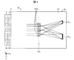
- FIG. 4 is a plan view showing a configuration for forming a plane image FI in the optical device 1A.
- FIG. 5 is a front view showing an example of the stereoscopic image I formed by the surface image FI formed by the optical device 1A.
- an oblique line-containing ring mark made of, for example, a plane image FI as a stereoscopic image I on a stereoscopic image imaging plane 30 parallel to the xz plane by the optical device 1A.
- the light propagating in the light guide plate 10 has a larger spread in the yz plane. Therefore, the incident light adjusting unit 3 does not reduce the spread angle of the light from the light source 2 in the yz plane. That is, the incident light adjusting unit 3 does not substantially affect the spread angle of the light from the light source 2 in the yz plane.
- the lens 3a included in the incident light adjusting unit 3 can be a convex cylindrical lens having a curvature in the xy plane and substantially having no curvature in the yz plane.
- This cylindrical lens is composed of, for example, convex lenses on both sides.
- first optical path deflecting unit groups 21a, 21b, 21c... Functioning as the surface image optical path deflecting unit group 21 are formed on the back surface 13.
- Each of the first optical path deflection unit groups 21a, 21b, 21c,... Is formed of a plurality of prisms provided along a direction parallel to the x axis.
- the first optical path deflection unit group 21a is composed of a plurality of prisms P21a.
- the first optical path deflection unit group 21b includes a plurality of prisms P21b
- the first optical path deflection unit group 21c also includes a plurality of prisms P21c.
- the prism P21a deflects the incident light in the optical path, spreads it in the direction parallel to the xy plane, and emits it from the emission surface 12.
- the light beam emitted from the emission surface 12 by the prism P21a substantially intersects the stereoscopic image forming surface 30 with a line.
- two light beams are emitted from the emission surface 12 by the prism P21a.
- Two light beams emitted intersect at the stereoscopic image imaging plane 30 and the line 31a 1 and line 31a 2.
- any prism P21a included in the first optical path deflecting portion group 21a like the other prism P21a, a light beam that intersects with the stereoscopic image imaging plane 30 and the line 31a 1 and the line 31a 2
- the light is emitted from the emission surface 12.
- the line 31a 1 and the line 31a 2 are in a plane substantially parallel to the xy plane, and form a part of the stereoscopic image I.
- the light from a large number of prism P21a belonging to the first optical path deflecting portion group 21a, the line image LI of line 31a 1 and line 31a 2 is imaged.
- the light for forming an image of the line 31a 1 and line 31a 2 is only to be provided by at least two prisms P21a ⁇ P21a in the first optical path deflecting portion group 21a provided at different positions along the x-axis direction That's fine.
- each of the plurality of prisms P21a belonging to the first optical path deflecting portion group 21a the light incident on each of the plurality of prisms P21a, on the exit surface 12 in a plane parallel to the image line 31a 1 and the line 31a 2
- the light is spread in the x-axis direction to the light having an intensity distribution corresponding to the light and is emitted from the emission surface 12.
- the light from the plurality of prisms P21a arranged along the x-axis direction becomes the light that forms the image of the line 31a 1 and line 31a 2.
- each prism P21b of the first optical path deflecting unit group 21b deflects the incident light in the direction parallel to the xy plane, and emits three light beams on the exit surface 12. The light is emitted from.
- the three light beams emitted from the emission surface 12 intersect the stereoscopic image forming surface 30 at the lines 31b 1 , 31b 2 and 31b 3 .
- any prism P21b included in the first optical path deflecting portion group 21b like the other prism P21b, emitting surface 12 the light beams that intersect at the stereoscopic image imaging plane 30 and the line 31b 1 ⁇ 31b 2 ⁇ 31b 3 The light is emitted from.
- each of the plurality of prisms P21b belonging to the first optical path deflecting portion group 21b the light incident on each of the plurality of prisms P21b, on the exit surface 12 a plane parallel to the line 31b 1 ⁇ 31b 2 ⁇
- the light is spread in the x-axis direction to light having an intensity distribution corresponding to the image 31b 3 and is emitted from the emission surface 12.
- light from a plurality of prisms P21b arranged along the x-axis direction becomes the light that forms the image of the line 31b 1 ⁇ 31b 2 ⁇ 31b 3 .
- the line 31b 1 ⁇ 31b 2 ⁇ 31b 3 is substantially located in a plane parallel to the xy plane, images the portion of the stereoscopic image I.
- the imaging positions of the lines 31 b 1 , 31 b 2 , 31 b 3 and the imaging positions of the lines 31 a 1 , 31 a 2 are different in the z-axis direction in the stereoscopic image imaging plane 30.
- each prism P21c of the first optical path deflecting unit group 21c deflects the incident light in the direction parallel to the xy plane so that two light beams are emitted. The light is emitted from. Two light beams emitted from the exit surface 12 intersect at the stereoscopic image imaging plane 30 and the line 31c 1 and line 31c 2. Then, any prism P21c included in the first optical path deflecting unit group 21c emits the light beam intersecting the stereoscopic image imaging surface 30 at the lines 31c 1 and 31c 2 from the emission surface 12 in the same manner as the other prisms P21c. .
- each of the plurality of prisms P21c belonging to the first optical path deflecting unit group 21c is configured so that the light incident on each of the plurality of prisms P21c is reflected by the lines 31c 1 and 31c 2 in a plane parallel to the emission surface 12.
- the light is spread in the x-axis direction to light having an intensity distribution corresponding to the image and is emitted from the emission surface 12.
- light from the plurality of prisms P21c belonging to the first optical path deflection unit group 21c and arranged along the x-axis direction becomes light that forms an image on the lines 31c 1 and 31c 2 .
- the lines 31c 1 and 31c 2 are substantially in a plane parallel to the xy plane, and form a part of the stereoscopic image I.
- the imaging position of the line 31c 1 ⁇ 31c 2 and the imaging position of the line 31b 1 ⁇ 31b 2 ⁇ 31b 3 , the imaging position of the line 31a 1 ⁇ 31a 2, the stereoscopic image imaging plane 30 Inside, the positions in the z-axis direction are different.
- the imaging position of the line 31c 1 ⁇ 31c 2, and the imaging position of the line 31b 1 ⁇ 31b 2 ⁇ 31b 3 , the imaging position of the line 31a 1 ⁇ 31a 2 And the positions in the z-axis direction are different from each other in the three-dimensional image forming plane 30, and they are visually recognized separately.
- the first optical path deflecting unit groups 21a, 21b, 21c are composed of, for example, more first optical path deflecting unit groups than the first optical path deflecting unit groups 21a, 21b, 21c.
- deviation part group 21a * 21b * 21c can be narrowed.
- the lines 31a 1 and 31a 2 are connected.
- each position of the imaging position of the image position and the line 31b 1 ⁇ 31b 2 ⁇ 31b 3 of the imaging position and the line 31c 1 ⁇ 31c 2 can be brought close to each other in the z-axis direction.
- the surface image FI of the ring mark with diagonal lines is visually recognized as the stereoscopic image I.
- the light beam is surface-divided by the collection of light beams from the plurality of prisms P21a, P21b, 21c of the first optical path deflecting unit groups 21a, 21b, 21c,.
- the image FI can be imaged and provided to the viewer's space. Therefore, the observer can recognize the three-dimensional image I including the surface image FI from a wide position range along the y-axis direction.
- FIG. 6 is a perspective view of an exemplary configuration of the prism P21a formed on the light guide plate 10 in the optical device 1A.
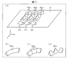
- FIG. 7A is a perspective view showing an example of the arrangement of the prisms P21a formed on the light guide plate 10 in the optical device 1A.
- FIGS. 7B, 7C, and 7D are perspective views showing a configuration of a modified example of the prism P21a.
- 8A, 8B, and 8C are plan views schematically showing arrangement examples of the prisms P21a to P21d formed on the light guide plate 10 in the optical device 1A.
- the prism P21a of the first optical path deflecting unit group 21a has, for example, a shape obtained by cutting off a part of a ring whose cross-sectional shape is a mountain shape, for example, the reflecting surfaces f1, f2, f3, f4, and f5.
- These reflecting surfaces f1, f2, f3, f4, and f5 are examples of optical surfaces that function as deflecting surfaces for deflecting light in the optical path, and are made of curved surfaces that face different directions.
- the optical axis of the light emitting diode (LED) 2a is inclined with respect to the emission surface 12 of the light guide plate 10 by the angle ⁇ in the yz plane.
- the light guide plate 10 repeats reflection at the exit surface 12 and the back surface 13.
- the amount of light guided can be increased. Therefore, the amount of light incident on the reflecting surfaces f1, f2, f3, f4, and f5 can be increased as compared with the case where the optical axis of the incident light is parallel to the y-axis.
- the reflection surface f1 is an upward inclined surface that is curved in an arc shape in a direction parallel to the light L1 guided through the light guide plate 10, and the light L1 incident on the reflection surface f1 is reflected on the reflection surface f1. Depending on the incident position, the light is emitted from the emission surface 12 at different emission angles. As a result, the reflection surface f1 spreads the light L1 incident on the reflection surface f1 to, for example, the range of the side 31 in the stereoscopic image I as shown in FIG. In the present embodiment, the side 31 is a side parallel to the y axis.
- the reflected light from the reflective surface f1 is directed in the direction in which the side 31 exists, and the light directed from the reflective surface f1 in the direction in which the side 31 does not exist is substantially absent. Therefore, the reflected light from the reflective surface f1 is substantially distributed only at an angle from the reflective surface f1 toward the side 31 in the yz plane. Thus, in the yz plane, the reflection surface f1 emits the incident light after intensity-modulating it in the angular direction. Since the reflecting surface f1 is a curved surface, even when the light L1 that is incident light on the reflecting surface f1 is parallel light, light for forming a line for drawing an image can be provided.
- the reflecting surfaces f2 and f3 extend in a circular arc across the reflecting surface f1 in a donut shape having a mountain-shaped cross section in the prism P21a, and are respectively similar to the reflecting surface f1. In the middle, it is an inclined surface that goes up the mountain slope.
- This result reflects the light L1 incident on the reflective surface f2 ⁇ f3, as shown in FIG. 3, extend the light the reflection in the range of the line 31a 1 and the line 31a 2 of the three-dimensional image I.
- FIG. 3 between the lines 31a 1 and the line 31a 2 of the three-dimensional image I, to form a state in which the line is not present due to the presence of the reflecting surface f1.
- the reflection surfaces f4 and f5 are further composed of climbing inclined surfaces formed through curved lines formed in the middle of the reflection surfaces f4 and f5.
- the presence of the reflective surface f4 ⁇ f5, as shown in FIG. 3, for example, can be imaged lines 31c 1 and the line 31c 2 of the three-dimensional image I.
- first optical path deflecting unit groups 21a, 21b, 21c each including a plurality of prisms P21a,..., Prisms P21b,. .
- the prisms P21a, P21b, and P21c shown in FIG. 7 (a) are, for example, those obtained by placing a triangular pyramid prism on the side.
- the present invention is not limited to this.
- the inflection portion is formed in a triangular pyramid having an arc shape or a triangular pyramid having an arc shape. It may be an attached one, or a triangular pyramid with one side formed in a wave shape.
- the arrangement method of the plurality of prisms P21a,..., Prisms P21c,... Shown in FIG. 7A is arranged in alignment along the y-axis direction, as shown in FIG. It has become an array.
- the arrangement method is not limited to this.
- a plurality of arc-shaped prisms P21a,..., Prisms P21b When viewed in order, it can be arranged so as to be shifted by a certain amount in the x-axis direction.
- one prism P21a, prism P21b, prism P21c, and prism P21d can be arranged continuously in a wave-like arc shape in the x-axis direction.
- the shapes of the first optical path deflection unit groups 21a, 21b, and 21c for forming the surface image FI the lines 31a 1 and 31a 2 and the lines 31b 1 and 31b 2 that are the basis of the surface image FI are used.
- the shapes of the prisms P21a, P21b, and P21c that form the image of 31b 3 and the lines 31c 1 and 31c 2 have been described.
- the shapes of the first optical path deflection unit groups 21a, 21b, and 21c for forming the surface image FI are not necessarily limited to this.
- the third optical path deflecting unit group 22 is formed as the optical path deflecting unit group 21 for forming the surface image FI. is there.
- FIG. 9 is a perspective view showing the shape of the prism P22 when the surface image FI is formed as a parallax image.
- the prism P ⁇ b> 22 has a convex reflection surface as a whole and is formed on the back surface 13 of the light guide plate 10.
- the convex reflecting surface of the prism P22 is formed so that the light guided through the light guide plate 10 is deflected in the optical path so that the light beam passing through the stereoscopic image forming surface 30 is emitted from the emitting surface 12. ing.
- an “A” character forming portion P22a in which a character “A” is formed is provided on the convex surface of the prism P22, and an antireflection film portion is provided in a portion other than the “A” character forming portion P22a.
- P22b is formed. The light incident on the antireflection film part P22b is not reflected.
- the prism P22 deflects the incident light in the optical path, and emits the light beam passing through the A-shaped stereoscopic image I from the emission surface 12.
- the antireflection film portion P22b can be formed, for example, by applying black paint on the back surface 13 of the light guide plate 10 except for the “A” character forming portion P22a.
- the antireflection film part P22b can also be formed by printing black paint except for the “A” character forming part P22a.
- the prism P22 can form the “A” character forming portion P22a by printing the black paint after forming the convex portion on the back surface 13 of the light guide plate 10. For this reason, the manufacture of the prism P22 is facilitated.
- the stereoscopic image I includes the surface image FI that is two-dimensionally spread in space and the contour image BI that is imaged as the contour of the surface image FI. It consists of a line image LI.
- the optical path deflecting unit 20 includes first optical path deflecting unit groups 21 a, 21 b, 21 c... As the surface image optical path deflecting unit group 21 that forms the surface image FI, and a contour image optical path that forms the line image LI.
- the second optical path deflecting unit group 25 is a deflecting unit group 24.
- FIG. 10 is a perspective view showing the configuration of the second optical path deflection unit group 25 that forms the line image LI.
- FIG. 10 it is considered to form, for example, a line image LI of the letter “A” as a stereoscopic image I in space.
- the second optical path deflecting unit groups 25a, 25b, 25c, 25d, 25e, 25f, and 25g are applied to the back surface 13 of the light guide plate 10 on which light from the light source 2 is incident.
- a plurality of contour image optical path deflecting unit groups 24 are formed.
- the number of light-emitting diodes (LEDs) 2a and the like of the light source 2 may be one instead of a plurality, and the installation location of the light source 2 is the opposite end surface facing the incident surface 11 of the light guide plate 10. May be. That is, it is possible to provide the light source 2 on the incident surface 11 side of the light guide plate 10 in order to form the surface image FI, and to provide the light source 2 on the opposite end surface of the incident surface 11 in order to form the line image LI. It is.
- the second optical path deflection unit groups 25a to 25g for forming the line image LI are each formed by a part of a Fresnel lens.
- the second optical path deflection unit groups 25a to 25g are formed substantially continuously in the x-axis direction.
- a gap may be provided between the plurality of refractive surfaces (prism surfaces) of the second optical path deflection unit groups 25a to 25g functioning as Fresnel lenses.
- the light guided by the light guide plate 10 is incident on each position in the x-axis direction of the second optical path deflection unit groups 25a to 25g.
- the second optical path deflection unit groups 25a to 25g substantially converge the light incident on the respective positions of the second optical path deflection unit groups 25a to 25g to fixed points respectively corresponding to the second optical path deflection unit groups 25a to 25g.
- FIG. 10 shows how a plurality of light beams from the second optical path deflecting unit groups 25a to 25g converge.
- the second optical path deflection unit group 25a corresponds to the point image PI of the fixed point PA of the stereoscopic image I, and light rays from each position of the second optical path deflection unit group 25a are fixed points of the stereoscopic image I. Converges to PA. Therefore, the wavefront of the light from the second optical path deflecting unit group 25a becomes a wavefront of light emitted from the fixed point PA.
- the second optical path deflection unit group 25b corresponds to the point image PI of the fixed point PB on the stereoscopic image I, and the light rays from each position from the second optical path deflection unit group 25b converge to the fixed point PB. To do. In this way, the light rays from the respective positions of the arbitrary second optical path deflection unit groups 25a to 25g converge at fixed points corresponding to the second optical path deflection unit groups 25a to 25g. As a result, a wavefront of light that emits light from a corresponding fixed point can be provided by any of the second optical path deflection unit groups 25a to 25g.
- the point images PI of the fixed points PA to PG corresponding to the second optical path deflection unit groups 25a to 25g are different from each other, and a space is obtained by a collection of a plurality of fixed points PA to PG respectively corresponding to the second optical path deflection unit groups 25a to 25g.
- a stereoscopic image I is formed on the top. In this way, the optical device 1A projects the stereoscopic image I on the space.
- the second optical path deflection unit groups 25a to 25g are formed in close contact along the y-axis direction.
- a collection of a plurality of fixed points PA to PG is substantially visually recognized by the human eye as a line image LI in the stereoscopic image I.
- the light beam guided by the light guide plate 10 and passing through each position in the light guide plate 10 has a smaller predetermined value around the direction connecting each position in the light guide plate 10 and the light source 2.
- a light beam that is guided by the light guide plate 10 and passes through each position in the light guide plate 10 in a plane that includes a line that connects each position in the light guide plate 10 and the light source 2 and is orthogonal to the xy plane is transmitted through the light guide plate 10.
- the second optical path deflecting unit groups 25a to 25g are provided at positions away from the light source 2, the light beams guided by the light guide plate 10 and incident on the second optical path deflecting unit groups 25a to 25g are approximately in the y-axis direction. As a center, there is no spread in the xy plane. Therefore, for example, on a plane that includes the fixed point PA and is parallel to the xz plane, the light from the second optical path deflecting unit group 25a substantially converges to one fixed point.
- the light from the second optical path deflection unit groups 25a to 25g includes a fixed point in space, as will be described later. Converge on a line along the y-axis.
- the spread of light in the xy plane of the light incident on the second optical path deflection unit groups 25a to 25g and the convergence of the light from the second optical path deflection unit groups 25a to 25g in the xz plane will be described. Therefore, description will be made assuming that the light from the second optical path deflecting unit groups 25a to 25g converges to a fixed point.
- the second optical path deflection unit group 25a is formed along a line.
- the second optical path deflection unit group 25b is also formed along the line.
- the second optical path deflection unit groups 25a and 25b are each formed by a straight line parallel to the x-axis.
- the arbitrary second optical path deflection unit groups 25a to 25g are formed substantially continuously along a straight line parallel to the x-axis.
- the second optical path deflection unit groups 25 a to 25 g are each formed with a length in a direction perpendicular to the light guide direction of the light guide plate 10 in a plane parallel to the emission surface 12.
- the second optical path deflection unit groups 25a to 25g are formed along predetermined lines in a plane parallel to the emission surface 12, respectively. Then, each of the second optical path deflection unit groups 25a to 25g is incident on the light guided by the light guide plate 10, and emits outgoing light in a direction substantially converging at one convergence point in space from the outgoing surface 12. Let it emit.
- an emitted light becomes a direction which diverges from a fixed point. Therefore, when the fixed point is on the rear surface 13 side of the light guide plate 10, the reflecting surfaces of the second optical path deflecting unit groups 25a to 25g emit outgoing light in a direction substantially diverging from one converging point in space. 12 is emitted.
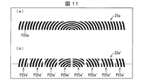
- FIG. 11A is a plan view showing the configuration of the second optical path deflection unit group 25a that forms a line image LI in the optical device 1A.
- FIG. 11B is a plan view showing a configuration of a modified example of the second optical path deflection unit group 25a that forms a line image LI in the optical device 1A.
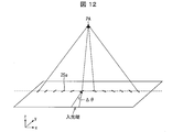
- FIG. 12 is a perspective view showing light collection by the second optical path deflecting unit group 25a shown in FIG.
- the second optical path deflection unit group 25a is imaged by, for example, a part of the Fresnel lens.
- the second optical path deflecting unit group 25a has, for example, a shape obtained by cutting concentric circles into strips.
- the central part of each second optical path deflection unit group 25a has a smaller central radius than the end part.
- the light incident on the central portion of the second optical path deflecting group 25a has a large curvature at the central portion as shown in FIG. 12, and therefore converges at a fixed point PA immediately above the central portion.
- the light incident on the end portion of the second optical path deflection unit group 25a has a small curvature at the end portion, so that it is refracted greatly and converges to a fixed point directly above the center portion.
- the prisms having different curvatures are arranged on a straight line, all the prisms converge on the fixed point PA.
- this fixed point PA is converged by many prisms P25a, the light quantity is large.
- the substantial line image LI formed by arranging these fixed points PA to PG naturally has a large amount of light.
- the line image LI imaged by the second optical path deflection unit group 25 has a large amount of light and becomes clear.
- the line image LI imaged by the second optical path deflection unit group 25 of the present embodiment is preferably used as the contour of the surface image FI imaged by the first optical path deflection unit group 21.
- each lens of the second optical path deflection unit group 25a may be partially provided with a large gap.
- the second optical path deflecting unit group 25a ' includes a plurality of lens groups P25a' along the x-axis direction.
- the front second optical path deflecting unit group 25a has an optical surface that continuously changes along the length direction of the second optical path deflecting unit group 25a, whereas the second optical path deflecting unit group 25a ′ includes a plurality of lenses. Like the group P25a ′, it has an optical surface that changes intermittently along the length direction of the second optical path deflection unit group 25a ′. As a result, the light from each lens group P25a 'of the second optical path deflection unit group 25a' converges to the same fixed point PA corresponding to the second optical path deflection unit group 25a '. At the fixed point PA, the light intensity distribution in the x-axis direction of the light from each of the lens groups P25a ′ substantially has a peak at the position of the fixed point PA, and decreases sharply as the distance from the fixed point PA increases. .
- the optical surface of the second optical path deflecting unit group 25a is a continuous optical surface without being separated in the x-axis direction, light from a certain partial surface of the optical surface is surrounded by the surrounding surface of the partial surface. Part of the light from the optical surface overlaps. For this reason, the intensity distribution in the x-axis direction of light from the corresponding partial surface becomes wider than when each lens group P25a 'is provided slightly apart in the x-axis direction. That is, by dividing the second optical path deflection unit group 25a ′ into a plurality of lens groups P25a ′ and separating them, the intensity distribution of light from each of the lens groups P25a ′ is broadened compared to the case where they are not separated. Can be reduced. Thus, by dividing the second optical path deflecting unit group 25a 'into a plurality of lens groups P25a', a so-called black matrix effect may occur, and the contrast of the image may increase.
- a diffraction grating may be applied as the second optical path deflection unit group 25a and the second optical path deflection unit group 25a 'instead of a cylindrical type Fresnel lens. Further, as the second optical path deflecting unit group 25a and the second optical path deflecting unit group 25a ', the second optical path deflecting unit group 25a formed of a reflecting surface such as a prism may be applied.
- the optical device 1A of the present embodiment forms a stereoscopic image I by combining a two-dimensional surface image FI and a line image LI for a contour image.
- the first optical path deflection unit groups 21a, 21b, 21c,... And the second optical path deflection unit groups 25a, 25b,... For forming a combination of the plane image FI for the plane image and the line image LI for the outline.
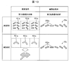
- Usage examples and arrangement examples of 25c... Will be described with reference to FIGS. 13 forms the surface image FI using the first optical path deflector groups 21a, 21b, 21c... For the surface image, while the first optical path deflector groups 21a, 21b, 21c.
- FIG. 14 is a diagram illustrating an arrangement example when the first optical path deflection unit groups 21a, 21b, 21c,... Are used for both the surface image and the contour image.
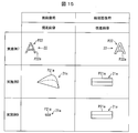
- FIG. 15 is a diagram illustrating a case where the first optical path deflection unit groups 21a, 21b, 21c,... Based on parallax images are used for both the surface image and the contour image.
- the first optical path deflecting unit groups 21a, 21b, 21c,... are imaged using the first optical path deflecting unit groups 21a, 21b, 21c..., While the first optical path deflecting unit groups 21a, 21b, 21c,.
- the line image LI can be formed.
- the first optical path deflection unit groups 21a, 21b, and 21c for forming the surface image FI three triangular pyramid prisms P21a, P21b, and P21c are provided. They are arranged in a matrix of 2 rows and 2 columns with a slight gap.
- the second optical path deflection unit group 25a for forming the line image LI can be arranged in a line.
- the first optical path deflection unit groups 21 a, 21 b, and 21 c for forming the surface image FI triangular pyramid prisms P ⁇ b> 21 a, P ⁇ b> 21 b, and P ⁇ b> 21 c are formed. A plurality of them are arranged close to each other.
- the second optical path deflecting unit group 25a for forming the line image LI can be arranged in a line as in the first embodiment.
- a contour to the surface image FI with a small amount of light by the first optical path deflection unit group 21a, 21b, 21c. Can be imaged.
- the first optical path deflection unit groups 21a, 21b, 21c,... Can be used for both the surface image and the contour image.
- Example 3 in FIG. 14 for example, as the first optical path deflection unit groups 21a, 21b, and 21c for forming the surface image FI, three triangular pyramid prisms P21a, P21b, and P21c are provided. They are arranged in a matrix of 2 rows and 2 columns with a slight gap. Further, the first optical path deflection unit groups 21a, 21b, and 21c for forming the line image LI are also arranged in substantially the same manner as described above.
- the sizes of the triangular pyramid prisms P21a, P21b, and P21c of the first optical path deflection unit groups 21a, 21b, and 21c for forming the line image LI are the same as those for forming the surface image FI. It is formed larger than the triangular pyramid prisms P21a, P21b, and P21c of the one optical path deflecting unit group 21a, 21b, and 21c.
- the first optical path deflecting unit groups 21a, 21b, and 21c for forming the surface image FI arc-shaped triangular pyramid prisms P21a, P21b, and P21c are used.
- the triangular pyramid prisms P21a, P21b, and P21c are respectively arranged in a matrix of 3 rows and 2 columns, as in the third embodiment. However, it arrange
- a part of one arc-shaped deformed triangular pyramid prism P21a is used to form a surface image FI for a surface image, and one arc-shaped prism P21a is used. It is possible to use the first optical path deflecting unit group 21a for another portion of the deformed triangular pyramid prism P21a for the contour image.
- one tapered cone-shaped prism P21a is used to form a surface image FI for a surface image, and one triangular pyramid prism P21a is contoured. It is possible to use the first optical path deflection unit group 21a for an image.
- the surface image FI for the surface image is formed by the first optical path deflecting unit group 21a, and the surface image FI for the surface image is formed by the first optical path deflecting unit group 21a for the contour image.
- a clear stereoscopic image I can be obtained by, for example, making the contrast different from the surface image FI for the surface image, or whitening the contour, for the contour image.
- the third optical path deflecting unit group 22 that forms the parallax image plane image FI can be used for both the plane image and the contour image.
- a prism P22 having, for example, an “A” character forming portion P22a that forms a parallax image plane image FI for both the plane image and the contour image.
- the provided third optical path deflecting unit group 22 can be used.
- the “A” character forming portion P22a for the surface image forms an image of the surface
- the “A” character forming portion P22a for the contour image forms an image of the contour.
- Example 8 in FIG. 15 for example, in order to form the first optical path deflection unit group 21a composed of one tapered conical prism P21a as the parallax image for the plane image FI.
- the first optical path deflection unit group 21a composed of one tapered conical prism P21a as the parallax image for the plane image FI.
- the first optical path deflecting unit group 21a is used as a parallax image for a plane image with one small triangular pyramid prism P21a, and one large triangular pyramid prism.
- the first optical path deflection unit group 21a can be used with P21a as the parallax image for the contour image.
- the first optical path deflection unit group 21a and the third optical path deflection unit group 22 that form the parallax image plane image FI can be used for both the plane image and the contour image.
- the optical device 1A has a surface image imaging unit that emits light so that a surface image FI having a predetermined shape is formed in space, and an outer edge region of the surface image FI.
- the image FI includes a contour image imaging unit that emits light so that a contour image BI having a different light intensity is imaged.
- a surface image FI having a predetermined shape is formed in a space, and a contour image BI having a light intensity different from that of the surface image FI is formed in an outer edge region of the surface image FI. .
- the plane image imaging unit forms a three-dimensional image I including the plane image FI having a predetermined shape on the space.
- the contour image imaging unit forms a three-dimensional image I composed of the contour image BI having a light intensity different from that of the surface image FI in the outer edge region of the surface image FI.
- the surface image FI has a stereoscopic effect by forming the boundary as a contour image BI with light having a light intensity different from that of the surface image FI. Come out. Therefore, it is possible to provide the optical device 1A and the stereoscopic display method that make it easy to visually recognize the stereoscopic effect.
- Application to figures, signs, etc. becomes possible.
- the display of the device the elevator floor logo display, the non-contact switch display, the status display such as “on”, and the like can be performed using the stereoscopic image I.
- the technology of the optical device 1A according to the present embodiment is not limited to this, and the first light control panel and the second light control panel formed by arranging strip-shaped planar light reflecting portions arranged at a constant pitch are orthogonal to each other.
- a technology for forming a stereoscopic image by forming them facing each other Patent Document 2
- a reflective surface-symmetric imaging element that transmits light and has a function of forming a real image at a plane-symmetric position, and a mirror surface.
- Patent Document 3 As a technique for forming a stereoscopic image of a real image of an object projected on a virtual mirror that does not exist (Patent Document 3) and a technique for forming a stereoscopic image using a microlens array (Patent Document 4) Can do.
- a three-dimensional image is synthesized by using a transmissive film as a half mirror such as a technique (Non-Patent Document 1) that generates plasma in the air to make a three-dimensional image appear, or so-called “Peppers ghost”.
- Non-Patent Document 1 Non-Patent Document 1
- the present invention can also be applied to a technique or a technique for forming a stereoscopic image by holography.
- each of the surface image imaging unit and the contour image imaging unit guides light incident from the light source 2 and emits it from the emission surface 12, and A plurality of optical path deflecting units 20 that are disposed on the light guide plate 10 and form a stereoscopic image I in space by deflecting the emitted light and emitting the light.
- the plurality of optical path deflecting units 20 includes, as the surface image forming unit, a surface image optical path deflecting unit group 21 that forms the surface image FI on the space by deflecting the emitted light and emitting the light.
- a contour image imaging unit includes a contour image optical path deflecting unit group 24 that forms the contour image BI in the space by deflecting the emitted light and emitting the light.
- the optical device 1A is configured by the light source 2 that makes light incident on the light guide plate 10 and the light guide plate 10 including the plurality of optical path deflecting units 20, and thus the configuration is simple.
- a surface image optical path deflecting unit group 21 that forms a surface image FI on the space by deflecting the emitted light and emitting the light
- a contour image optical path deflecting unit group 24 which forms a contour image BI in the space and having a contour different from the surface image FI by deflecting the guided light beam and emitting the light. I have.
- the plurality of optical path deflecting units 20 can be configured by the surface image optical path deflecting unit group 21 and the contour image optical path deflecting unit group 24, it is possible to easily configure the optical device 1A in which the stereoscopic effect can be easily visually recognized. it can.
- the contour image optical path deflecting unit group 24 forms the contour image BI having a light intensity stronger than that of the surface image FI, and the contour of the surface image FI as the contour image BI.
- the line image optical path deflecting unit group 25 forms an image of the line image LI.
- the contour image BI having a light intensity stronger than that of the surface image FI is formed by the optical path deflecting unit group 25 for line images. Therefore, a line image LI is formed on the surface image FI by the line image optical path deflecting unit group 25, and the line image LI has a light intensity stronger than that of the surface image FI.
- the optical device 1A since the boundary of the surface image FI is formed by the line image LI having a high light intensity, it is possible to provide the optical device 1A in which the stereoscopic effect can be easily visually recognized.
- the contour image optical path deflecting unit group 24 includes prisms P25a, P25b, P25c, P25d, P25e, and P25f as a plurality of second optical path deflecting units that form the point image PI.
- a plurality of second optical path deflection unit groups 25 made of P25g a line image LI is formed in appearance.
- the light guide plate 10 that guides light in a plane parallel to the emission surface 12 and the light guided by the light guide plate 10 enter, and enter one convergence point or convergence line in space.
- a plurality of light converging portions each having an optical surface that emits the exit light from the exit surface 12 in a direction substantially converging or substantially diverging from one convergence point or convergence line in space.
- the converging portions are formed along predetermined lines in a plane parallel to the exit surface 12, and the converging points or converging lines are different from each other among the plural light converging portions, and the plural converging points or converging lines are formed.
- An image is formed on the space by the gathering.
- each of the prisms P25a, P25b, P25c, P25d, P25e, P25f, and P25g in the second optical path deflecting unit group 25 forms an image on one point image PI, and thus one point image PI has a high light intensity. It becomes.
- the point images PI formed by the second optical path deflecting unit group 25 are arranged in a plurality of rows as the second optical path deflecting unit group 25 as second optical path deflecting unit groups 25a, 25b, 25c, 25d, 25e, 25f, and 25g. Since they are provided, the point images PI are arranged side by side, and are apparently recognized as line images LI.
- the second optical path deflecting unit group 25 having a plurality of prisms P25a, P25b, P25c, P25d, P25e, P25f, and P25g as the optical path deflecting unit 20 imaged on the light guide plate 10, the light intensity is increased.
- a contour image BI composed of a strong line image LI can be easily formed.
- the surface image optical path deflecting unit group 21 includes a plurality of prisms P21a, P21b, P21c,... As a first optical path deflecting unit that forms a line image LI.
- the surface image FI is formed in appearance.
- the optical device 1A is arranged two-dimensionally in the light guide plate 10 that propagates the light from the light source 2 in a plane parallel to the emission surface 12 and in the plane parallel to the emission surface 12, respectively.
- a plurality of light deflectors for deflecting light propagating in the optical plate 10 and emitting light forming an image in space from the exit surface 12, each of the plurality of light deflectors being a plurality of light deflectors.
- Light from a plurality of light deflection units arranged along a direction orthogonal to the light guide direction becomes light in a direction that forms an image or diverges from the image.
- the optical device 1 ⁇ / b> A is two-dimensionally arranged in a light guide plate 10 that propagates light from the light source 2 in a plane parallel to the emission surface 12 and in a plane parallel to the emission surface 12.
- the light incident on the light beam is two-dimensionally spread into light having an intensity distribution according to the image and emitted from the emission surface 12, so that light from three or more light deflecting units that are not on the same straight line is coupled to the image.
- the light is in a direction to image or diverge from the image.
- a line image LI constituting a part of the surface image FI is formed by the first optical path deflecting unit groups 21a, 21b, 21c... As the optical path deflecting unit 20 formed on the light guide plate 10. Since the first optical path deflection unit groups 21a, 21b, 21c,... Are provided in a plurality of rows, the thickness of the line image LI is thick. As a result, an apparent two-dimensional surface image FI is formed.
- the surface image optical path deflecting unit group 21 may be composed of a third optical path deflecting unit group 22 that forms the surface image FI by a parallax image.
- the surface image optical path deflecting unit group 21 that forms the surface image FI and the contour image optical path deflecting unit group 24 that forms the contour image BI have a pattern shape and size. At least one of them is different from each other. As a result, the surface image FI and the contour image BI can be formed different from each other.
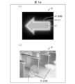
- the surface image FI and the line image LI serving as the contour are different in color. .
- the surface image FI is green
- the line image LI is white
- the surface image FI and the line image LI are changed in color. This makes it easier to obtain a stereoscopic effect and makes it easier to visually recognize a stereoscopic image.
- optical device 1B of the present embodiment can take other methods in order to make it easy to visually recognize a stereoscopic image.
- a contour image BI made of a line image LI is formed in the outer edge region of the surface image FI, and outside the contour image BI made of the line image LI.
- An optical device 1B ′ on which a white contour image BI is further formed can be used.
- a stereoscopic effect can be easily obtained, and the stereoscopic image I can be easily viewed. It is also possible to give a high-class feeling to the stereoscopic image I.
- a contour image BI including a line image LI is formed on the outer edge region of the surface image FI, and a gap d is formed between the surface image FI and the contour image BI. It is also possible to form an image with
- Embodiment 3 The following will describe still another embodiment of the present invention with reference to FIGS.
- the configurations other than those described in the present embodiment are the same as those in the first and second embodiments.
- members having the same functions as those shown in the drawings of Embodiments 1 and 2 are given the same reference numerals, and descriptions thereof are omitted.
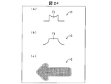
- the surface image FI formed by the surface image optical path deflecting unit group 21 is the interior of the surface image FI. The difference is that the images are formed so that the light intensity in the region and the outer edge region is the same.
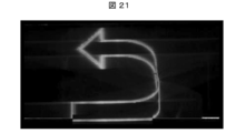
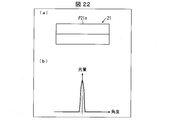
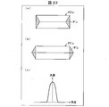
- the surface image FI formed by the optical device obtains the light intensity of the square-shaped corner image FI at the design stage.
- the actual light intensity distribution of the surface image FI is a light intensity distribution with no corners as shown in FIG. 20B, and the surface image FI as shown in FIG. 20C and FIG. Blur occurs in the outer edge area of the FI.
- This cause is considered to be due to the processing accuracy of the prism P21a of the surface image optical path deflection unit group 21 formed on the light guide plate 10 for forming the surface image FI, that is, processing distortion.
- the optical device 1C has an outer edge region of the surface image FI formed by the surface image optical path deflecting unit group 21 in the design stage.
- the light intensity is made stronger than the inside of the outer edge region of the surface image FI.
- the distribution of the light intensity of the actual surface image FI formed by the surface image optical path deflecting unit group 21 corresponds to the inner region and the outer edge region of the surface image FI. Images are formed so that the light intensities are the same.
- the shape of the surface image FI can be recognized even if the outer edge region of the surface image FI is blurred.
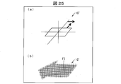
- the intensity distribution is improved only in the lateral direction.
- the present invention is not limited to this, and as shown in FIG. 25A, an optical device 1C ′ that improves the intensity distribution in both the horizontal direction and the vertical direction can be obtained.
- the surface image FI formed by the surface image optical path deflecting unit group 21 has the same light intensity in the inner region and the outer edge region of the surface image FI. Is imaged.
- the change in light intensity becomes steep between the outer edge area and the outer edge area of the surface image FI.
- the shape of the surface image can be recognized even if the outer edge region of the surface image FI is blurred.
- the light intensity for the outer edge area of the surface image FI can be increased as compared with the light intensity of the inner area.
- the actual stereoscopic image I it is possible to form an image so that the light intensity of the inner area and the outer edge area of the surface image FI is the same.
- Embodiment 4 The following will describe still another embodiment of the present invention with reference to FIGS.
- the configurations other than those described in the present embodiment are the same as those in the first to third embodiments.
- members having the same functions as those shown in the drawings of Embodiments 1 to 3 are given the same reference numerals, and descriptions thereof are omitted.
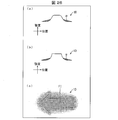
- the optical device 1D of the present embodiment has a light intensity outside the outer edge region of the surface image FI formed by the surface image optical path deflecting unit group 21.
- the difference is that the light intensity outside the outer edge region of the surface image FI is increased so that the difference from the light intensity inside the surface image FI is reduced. Further, the light intensity outside the outer edge region of the surface image FI is increased so that a singular point is formed in the light intensity curve outside the outer edge region of the surface image FI formed by the surface image optical path deflecting unit group 21. Is different.
- the light intensity distribution in the surface image FI is low at the base. It has become.
- the low light intensity is increased by the light intensity ⁇ , respectively, at the base of the light intensity distribution shown in FIGS.
- a singular point in which the angle is suddenly changed is generated in a curve in which the light intensity decreases from the contour of the surface image FI toward the periphery thereof. That is, at the position of this singular point, a discontinuous line due to a sudden change in the degree of blur can be generated outside the outer edge region of the surface image FI.
- the shape of the surface image FI can be recognized even if the outer edge region of the surface image FI is blurred.
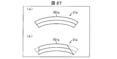
- the prism P21a of the first optical path deflecting unit group 21a for increasing the low light intensity by the light intensity ⁇ at the base in such a light intensity distribution is, for example, in an arc shape shown in FIG. What is necessary is just to form the edge part of the formed prism P21a so that a reflective surface may gradually decrease, as shown in FIG.27 (b).
- the light intensity outside the outer edge region of the surface image FI formed by the surface image optical path deflecting unit group 21 and the surface image FI is increased so that the difference from the internal light intensity becomes small.
- the optical device 1D allows the surface image FI to have a singular point in the light intensity curve outside the outer edge region of the surface image FI formed by the surface image optical path deflecting unit group 21. The light intensity outside the outer edge region is increased.
- the optical device 1E according to the present embodiment includes an optical path deflection unit group 21 for surface images in addition to the configuration of the optical device 1A according to the first embodiment.
- the imaged surface image FI is different in that a pattern is added.
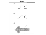
- the surface image FI was imaged by solid coating.
- the stereoscopic image I is more easily recognized when the texture is applied than when the solid coating is applied.
- a hatched pattern is added as shown in FIG. 28B, or a straight hatched pattern is added as shown in FIG. Or
- a pattern such as a striped pattern is imaged as a texture, so that, as shown in FIG. Can be provided.
- the optical device 1F of the present embodiment has, as shown in FIGS. 29 (a) and 29 (b), at least one side of the surface image FI.
- the difference is that a contour image BI corresponding to the shadow SD of the surface image FI is formed.
- the shadow SD of the surface image FI is imaged together with the surface image FI, thereby providing the optical device 1F in which the stereoscopic effect is easy to visually recognize.
- the shadow SD may be formed by either the surface image FI or the line image LI.
- the optical device includes a surface image imaging unit that emits light so that a surface image of a predetermined shape is imaged on a space, and A contour image imaging unit that emits light so as to form a contour image having a light intensity different from that of the surface image is provided in an outer edge region of the surface image.
- a surface image imaging unit forms a surface image of a predetermined shape in space, and the contour image imaging unit forms the surface image on the outer edge region of the surface image.
- a contour image having a light intensity different from that of the surface image is formed.
- the boundary image is formed as a contour image with light having a light intensity different from that of the surface image, so that the surface image has a three-dimensional effect.
- the optical device is the optical device according to the above aspect, wherein the contour image imaging unit forms a contour image having a light intensity stronger than the surface image, and the contour image includes the surface image.
- the image forming unit includes a line image contour image forming unit that forms a line image as a contour.
- a contour image having a light intensity stronger than that of the plane image is formed by the line image contour image imaging unit as the contour image imaging unit. For this reason, a line image is formed on the surface image by the line image contour image forming unit, and the light intensity of the line image is higher than that of the surface image.
- the surface image and the line image are different in color.
- the surface image is formed with a chromatic color such as green, and a line image such as white is formed as a contour image.
- a contour image including the line image is formed on an outer edge region of the surface image, and a white color is formed outside the contour image including the line image.
- a contour image is further formed.
- a contour image composed of a line image is formed on the outer edge region of the surface image, and a white contour image is further formed on the outer side thereof.
- a stereoscopic effect can be easily obtained, and a stereoscopic image can be easily viewed. It is also possible to give a high-class feeling to a stereoscopic image.
- a contour image including the line image is formed in an outer edge region of the surface image, and the surface image and the contour image are between the surface image and the contour image.
- An image is formed with a gap.
- the contour image composed of the line image is formed with a gap between the surface image.
- a dark part is formed between the surface image and the contour image composed of the line image.
- the surface image formed by the surface image imaging unit is provided with a pattern.
- an optical device by forming a pattern such as a striped pattern as a texture, an optical device can be provided in which a stereoscopic effect is easier to visually recognize than a solid-coated surface image.
- a contour image corresponding to a shadow of the surface image is formed on at least one side of the surface image.
- each of the surface image imaging unit and the contour image imaging unit guides light incident from a light source and emits the light from an output surface.
- the surface image imaging unit includes a surface image optical path deflecting unit group that forms the surface image in space by deflecting and emitting the guided light as an optical path, and forming the contour image And a contour image optical path deflecting unit group that forms the contour image in space by deflecting and emitting the guided light.
- the optical device is configured by a light source that makes light incident on the light guide plate and a light guide plate that includes a plurality of optical path deflecting units, so that the configuration is simple.
- a plane image optical path deflecting unit group that forms a plane image on a space by deflecting the emitted light and emitting the light
- the light guide A contour image optical path deflecting unit group that forms a contour image of a surface image on the space and forms a contour image having a light intensity different from that of the surface image by deflecting the emitted light and emitting it.
- the plurality of optical path deflecting units can be configured by the surface image optical path deflecting unit group and the contour image optical path deflecting unit group, it is possible to easily configure an optical device in which a stereoscopic effect can be easily visually recognized.
- the optical device is the optical device described above, wherein the contour image optical path deflection unit group includes a plurality of second optical path deflection unit groups each including a plurality of second optical path deflection units that form point images.
- the contour image optical path deflection unit group includes a plurality of second optical path deflection unit groups each including a plurality of second optical path deflection units that form point images.
- each of the second optical path deflecting units in the second optical path deflecting unit group forms an image on one point image, one point image has a high light intensity.
- the point image formed by the second optical path deflecting unit group has a plurality of second optical path deflecting unit groups, so that the point images are arranged side by side, and is apparently recognized as a line image. .
- a contour image composed of a line image with high light intensity can be easily formed. be able to.
- the optical device is the optical device described above, wherein the surface image optical path deflection unit group includes a plurality of first optical path deflection unit groups each including a plurality of first optical path deflection units that form a line image. By providing it, the surface image is apparently formed.
- a line image constituting a part of the surface image is formed by the first optical path deflecting unit group as the optical path deflecting unit formed on the light guide plate. And since the 1st optical path deflection
- a two-dimensional surface image can be easily formed by providing a plurality of first optical path deflection unit groups as optical path deflection units formed on the light guide plate.
- the optical device is the optical device described above, wherein the surface image optical path deflecting unit group includes a third optical path deflecting unit group that forms the surface image by a parallax image.
- the optical device is the optical device described above, wherein the surface image optical path deflection unit group that forms the surface image and the contour image optical path deflection unit group that forms the contour image. At least one of the pattern shape and the size is different from each other.
- the surface image and the contour image can be formed different from each other.
- the optical device is the optical device described above, wherein the surface image formed by the surface image optical path deflection unit group has the same light intensity in the inner region and the outer edge region of the surface image.
- the image is formed as follows.
- the light intensity changes sharply between the outer edge area and the outer edge area of the surface image.
- the shape of the surface image can be recognized even if the outer edge region of the surface image is blurred.
- An optical device is the above-described optical device, wherein a reflection surface in the first optical path deflection unit group of the surface image optical path deflection unit group is a reflection surface for an internal region of the plane image. It is formed so that the ratio of the reflecting surface for the outer edge region is increased.
- An optical device is the above-described optical device, wherein the light intensity outside the outer edge region of the surface image formed by the surface image optical path deflection unit group and the light intensity inside the surface image are The light intensity outside the outer edge region of the surface image is increased so that the difference between the two is smaller.
- the light intensity curve outside the outer edge region of the surface image formed by the surface image optical path deflecting unit group may have a singular point. The light intensity outside the outer edge region of the area image is increased.
- a surface image having a predetermined shape is formed in a space, and a contour image having a light intensity different from that of the surface image is formed in an outer edge region of the surface image. It is said.
- Optical device Light source (surface image imaging unit, contour image imaging unit) 2a Light Emitting Diode (LED) 3 Incident light adjustment unit 3a Lens 10 Light guide plate (surface image imaging unit, contour image imaging unit) DESCRIPTION OF SYMBOLS 11 Entrance surface 12 Output surface 13 Back surface 20 Optical path deflection
- deviation part A surface image image formation part, an outline image image formation part 21.
Landscapes
- Physics & Mathematics (AREA)
- General Physics & Mathematics (AREA)
- Optics & Photonics (AREA)
- Engineering & Computer Science (AREA)
- Theoretical Computer Science (AREA)
- Business, Economics & Management (AREA)
- Accounting & Taxation (AREA)
- Marketing (AREA)
- General Engineering & Computer Science (AREA)
- Stereoscopic And Panoramic Photography (AREA)
- Optical Elements Other Than Lenses (AREA)
Abstract
立体感を視認し易い光デバイス及び立体表示方法を提供する。光デバイス(1A)は、光源(2)から入射された光を導光して出射面(12)から出射する導光板(10)と、導光板(10)に配置され、導光された光を光路偏向して出射させることにより空間上に画像を結像させる複数の光路偏向部(20)とを備えている。光路偏向部(20)は、導光された光を光路偏向して出射させることにより空間上に面画像(FI)を結像させる面画像用光路偏向部群(21)と、導光された光を光路偏向して出射させることにより空間上に輪郭画像(BI)を結像させる輪郭画像用光路偏向部群(24)とを備えている。
Description
本発明は、立体画像を表示する光デバイス及び立体表示方法に関するものである。
従来、立体画像を表示する光デバイスとして、例えば、特許文献1に開示された画像表示装置が知られている。
前記特許文献1に開示された画像表示装置100は、図30の(a)に示すように、導光板110と、導光板110の端部に設けられた光源101と、導光板110の裏面に形成された複数の第1プリズムを有する左目用表示パターン111a・112a・113aと、導光板110の裏面に形成された複数の第2プリズムを有する右目用表示パターン111ba・112b・113bとを含んでいる。図30の(b)に示すように、前記左目用表示パターン111aは、複数の第1プリズムP1によって2次元の面「A」を形成し、右目用表示パターン111bは、複数の第2プリズムP2によって2次元の面「A」を形成するようになっている。
この構成により、光源101からの光を複数の第1プリズムと第2プリズムとで反射することによって導光板110の表面側に左眼用画像と右眼用画像が表示される。そして、観察者がこれらの左眼用画像及び右眼用画像を観察すると、図30の(c)に示すように、奥側から手前側に向かって面画像「A」、面画像「B」、面画像「C」の順に各観察画像120が配置された立体感のある面画像を観測することができる。各観察画像120はそれぞれの左眼用画像及び右眼用画像からの光線の光路上にある交点で浮かび上がっているかのように観測されるため、間隔の大きい方がより観測者に近い側に交点を持ち、より手前となる。したがって、観測者は、自然な状態で立体的な表示を視認することができる。
「産総研:空中に浮かび上がる3次元(3D)映像」, https://www.aist.go.jp/Portals/0/resource_images/aist_j/aistinfo/aist_today/vol06_04/vol06_04_p16_19.pdf,2006.04
しかしながら、前記従来の画像表示装置100では、空間に結像された立体画像が面画像のみからなっているので、面画像と空間との境界が明瞭でなく立体感を感じ難いという問題点を有している。
本発明は、前記従来の問題点に鑑みなされたものであって、その目的は、立体感を視認し易い光デバイス及び立体表示方法を提供することにある。
本発明の一態様における光デバイスは、前記課題を解決するために、空間上に所定形状の面画像が結像されるように光を出射する面画像結像部と、前記面画像の外縁領域に、該面画像とは光強度が異なる輪郭画像が結像されるように光を出射する輪郭画像結像部とを備えることを特徴としている。
本発明の一態様における立体表示方法は、空間に所定形状の面画像を結像させると共に、前記面画像の外縁領域に、該面画像とは光強度が異なる輪郭画像を結像させることを特徴としている。
本発明の一態様によれば、立体感を視認し易い光デバイス及び立体表示方法を提供するという効果を奏する。
〔実施の形態1〕
本発明の一実施形態を図1~図16に基づいて説明すれば、以下のとおりである。
本発明の一実施形態を図1~図16に基づいて説明すれば、以下のとおりである。
(光デバイスの構成)
本実施の形態の光デバイス1Aの構成を、図1及び図2に基づいて説明する。図1は本実施の形態の光デバイス1Aの構成を示す斜視図である。図2は、光デバイス1Aの構成を示す断面図である。
本実施の形態の光デバイス1Aの構成を、図1及び図2に基づいて説明する。図1は本実施の形態の光デバイス1Aの構成を示す斜視図である。図2は、光デバイス1Aの構成を示す断面図である。
図1に示すように、本実施の形態の光デバイス1Aは、面画像結像部及び輪郭画像結像部として、それぞれ、光源2と、光源2から入射された光を導光して出射面12から出射する導光板10と、導光板10に配置され、導光された光を光路偏向して出射させることにより空間上に立体画像Iを結像させる複数の光路偏向部20とを備えている。また、複数の光路偏向部20は、面画像結像部として、導光された光を光路偏向して出射させることにより空間上に面画像FIを結像させる面画像用光路偏向部群21を備えると共に、輪郭画像結像部として、導光された光を光路偏向して出射させることにより空間上に輪郭画像BIを結像させる輪郭画像用光路偏向部群24とを備えている。
前記光源2は、複数の例えば発光ダイオード(LED)2aにて構成されている。各発光ダイオード(LED)2aから出射された光は、入射光調節部3にて調整されて、導光板10の入射面11に入射する。尚、本実施の形態では、光源2は、複数の例えば発光ダイオード(LED)2a等からなっているが、必ずしもこれに限らず、単数の例えば発光ダイオード(LED)2a等からなっていてもよい。また、単数の例えば発光ダイオード(LED)2a等は、入射面11に対向する側面に設けられていてもよい。
入射光調節部3は、発光ダイオード(LED)2aに対して1対1に対応するように複数のレンズ3aを備えている。各レンズ3aは、対応する発光ダイオード(LED)2aの出射光の光軸に沿う方向の後述するxy平面の光の広がりを小さくしたり、大きくしたり、変化しないようにしたりする。この結果、レンズ3aは、発光ダイオード(LED)2aからの出射光を平行光に近づけたり、導光板10の内部において全域に導光したりする。導光板10によって導かれている光の広がり角は、5°以下であってよく、好ましくは1°未満である。尚、導光板10内のxy面内における光の広がり角を小さくするための他の構成として、例えば、x軸方向に所定幅よりも小さい開口を持つマスクを入射光調節部3に有していてもよい。
ここで、本実施の形態では、図2に示すように、発光ダイオード(LED)2aの出射光の光軸は、後述する出射面12に対して角度θを有している。例えば、発光ダイオード(LED)2aの出射光の光軸と出射面12とがなす狭角である角度θは、約20°である。この結果、導光板10への入射光が平行光に近い場合でも、入射光の光軸がy軸に平行である場合と比べて、出射面12と後述する裏面13とで反射を繰り返しながら導光板10内を導光する光量を増やすことができる。したがって、入射光の光軸がy軸に平行である場合と比べて、後述する光路偏向部20に入射する光量を増やすことができる。
導光板10は、透明でありかつ屈折率が比較的高い樹脂材料で成形される。導光板10を形成する材料としては、例えばポリカーボネート樹脂(PC)、ポリメチルメタクリレート樹脂(PMMA)ガラス等を使用することができる。
導光板10は、光源2からの光が入射される入射面11と、導光板10の表面である光を出射する出射面12と、光路偏向部20が形成されている裏面13とを有している。
本実施の形態では、導光板10の出射面12から光が出射され、その出射された光によって、空間中に立体画像Iが結像される。立体画像Iは、観察者によって立体的に認識される。尚、立体画像Iとは、導光板10の出射面12とは異なる位置に存在するように認識される像をいう。立体画像Iは、例えば、導光板10の出射面12から離れた位置に認識される2次元像も含む。つまり、立体画像Iは、立体的な形状として認識される像だけでなく、光デバイス1Aとは異なる位置に認識される2次元的な形状の像も含む概念である。本実施の形態においては、立体画像Iは出射面12よりもz軸プラス側に位置するとして説明する。ただし、立体画像Iは出射面12よりもz軸マイナス側に位置する場合もある。
尚、本実施の形態の説明において、x軸、y軸及びz軸からなる直交座標系を用いる場合がある。本実施の形態では、z軸方向を、出射面12に垂直な方向として定めると共に、裏面13から出射面12への向きをz軸プラス方向と定める。また、y軸方向を、入射面11に垂直な方向として定めると共に、入射面11からこの入射面11に対向する面画像FIへの向きをy軸プラス方向と定める。さらに、x軸は、入射面11に直交する導光板10の側面間の方向であって、図1において左の側面から右の側面への方向をx軸プラス方向として定める。尚、記載が冗長にならないよう、xy平面に平行な面のことをxy面、yz平面に平行な面のことをyz面、xz平面に平行な面のことをxz面と呼ぶ場合がある。
本実施の形態の光デバイス1Aでは、導光板10の裏面13には、導光板10にて導光された光を光路偏向して出射させることにより空間上に像としての立体画像Iを結像させる複数の光路偏向部20が形成されている。これら複数の光路偏向部20は、xy面内において2次元的にそれぞれ互いに異なる位置に例えばマトリクス状に形成されている。光路偏向部20は例えばプリズムからなっている。
すなわち、前述したように、図2において、光源2から出射された光は、入射光調節部3を介して導光板10の入射面11から入射される。導光板10に入射された光は、導光板10の出射面12と裏面13との間を全反射して奥方へ導光される。そして、光路偏向部20によって、全反射条件が破られ、光の光路が特定の向きに偏向されて出射面12から出射されるものとなっている。
ここで、本実施の形態の光デバイス1Aでは、図1に示すように、立体画像Iは、空間上に所定形状に結像された面画像FIと、面画像FIの外縁領域に結像された輪郭画像BIとからなっている。そして、面画像FIと輪郭画像BIとは光強度が互いに異なっている。
特に、本実施の形態の光デバイス1Aは、輪郭画像BIは線画像LIからなっている。
前記面画像FIを結像させる面画像用光路偏向部群21としての第1光路偏向部群21a・21b・21c…と、輪郭画像BIとしての線画像LIを結像させる輪郭画像用光路偏向部群24としての第2光路偏向部群25との構成及び機能について、以下に順に説明する。
(面画像を結像するための構成)
最初に、本実施の形態の光デバイス1Aにおける面画像FIを結像させるための構成について、図3~図5に基づいて説明する。図3は、光デバイス1Aにおける面画像FIを結像させるための構成を示す斜視図である。図4は、光デバイス1Aにおける面画像FIを結像させるための構成を示す平面図である。図5は、光デバイス1Aによって結像された面画像FIからなる立体画像Iの一例を示す正面図である。
最初に、本実施の形態の光デバイス1Aにおける面画像FIを結像させるための構成について、図3~図5に基づいて説明する。図3は、光デバイス1Aにおける面画像FIを結像させるための構成を示す斜視図である。図4は、光デバイス1Aにおける面画像FIを結像させるための構成を示す平面図である。図5は、光デバイス1Aによって結像された面画像FIからなる立体画像Iの一例を示す正面図である。
図3に示すように、例えば、光デバイス1Aにてxz面に平行な立体画像結像面30に立体画像Iとして例えば面画像FIからなる斜め線入りリングマークを結像することを考える。
本実施の形態の光デバイス1Aでは、導光板10内を伝播する光のyz面内における広がりが大きい方が好ましい。そこで、入射光調節部3は、光源2からの光のyz面内における広がり角を小さくしない。すなわち、入射光調節部3は、光源2からの光のyz面内における広がり角に実質的に影響を与えない。
例えば、入射光調節部3が有するレンズ3aは、xy面内で曲率を持ち、yz面内で曲率を実質的に持たない凸状のシリンドリカルレンズとすることができる。このシリンドリカルレンズは、例えば、両面が凸レンズからなっている。
光デバイス1Aの導光板10には、裏面13に面画像用光路偏向部群21として機能する複数の第1光路偏向部群21a・21b・21c…が形成されている。各第1光路偏向部群21a・21b・21c…は、それぞれx軸に平行な方向に沿って設けられた複数のプリズムから形成されている。例えば、第1光路偏向部群21aは、複数のプリズムP21aから構成されている。同様に、第1光路偏向部群21bは、複数のプリズムP21bから構成され、第1光路偏向部群21cも、複数のプリズムP21cから構成されている。
例えばプリズムP21aは、入射した光を光路偏向してxy面内に平行な方向に広げて、出射面12から出射させる。プリズムP21aによって出射面12から出射した光束は、立体画像結像面30と実質的に線で交差する。図3及び図4に示すように、プリズムP21aによって出射面12から2つの光束が出射される。出射した2つの光束は、立体画像結像面30と線31a1及び線31a2で交差する。図3に示すように、第1光路偏向部群21aに含まれるいずれのプリズムP21aも、他のプリズムP21aと同様に、立体画像結像面30と線31a1及び線31a2で交差する光束を出射面12から出射させる。線31a1及び線31a2は、実質的にxy面に平行な面内にあり、立体画像Iの一部を結像する。このように、第1光路偏向部群21aに属する多数のプリズムP21aからの光によって、線31a1及び線31a2の線画像LIが結像される。尚、線31a1及び線31a2の像を結像する光は、x軸方向に沿って異なる位置に設けられた第1光路偏向部群21aにおける少なくとも2つのプリズムP21a・P21aによって提供されていればよい。
すなわち、第1光路偏向部群21aに属する複数のプリズムP21aのそれぞれは、複数のプリズムP21aのそれぞれに入射した光を、出射面12に平行な面内で、線31a1及び線31a2の像に応じた強度分布の光にx軸方向に広げて、出射面12から出射させる。これにより、第1光路偏向部群21aに属し、x軸方向に沿って配置された複数のプリズムP21aからの光が、線31a1及び線31a2の像に結像する光になる。
図3に示すように、同様にして、第1光路偏向部群21bの各プリズムP21bは、入射した光を光路偏向してxy面内に平行な方向に広げて、3つの光束を出射面12から出射させる。出射面12から出射した3つの光束は、立体画像結像面30と線31b1、線31b2及び線31b3で交差する。そして、第1光路偏向部群21bに含まれるいずれのプリズムP21bも、他のプリズムP21bと同様に、立体画像結像面30と線31b1・31b2・31b3で交差する光束を出射面12から出射させる。このように、第1光路偏向部群21bに属する複数のプリズムP21bのそれぞれは、複数のプリズムP21bのそれぞれに入射した光を、出射面12に平行な面内で、線31b1・31b2・31b3の像に応じた強度分布の光にx軸方向に広げて、出射面12から出射させる。これにより、第1光路偏向部群21bに属し、x軸方向に沿って配置された複数のプリズムP21bからの光が、線31b1・31b2・31b3の像に結像する光になる。尚、線31b1・31b2・31b3は、実質的にxy面に平行な面内にあり、立体画像Iの一部を結像する。
ここで、線31b1・31b2・31b3の結像位置と、前記線31a1・31a2の結像位置とは、立体画像結像面30内においてz軸方向の位置が異なる。
図3に示すように、同様にして、第1光路偏向部群21cの各プリズムP21cは、入射した光を光路偏向してxy面内に平行な方向に広げて、2つの光束を出射面12から出射させる。出射面12から出射した2つの光束は、立体画像結像面30と線31c1及び線31c2で交差する。そして、第1光路偏向部群21cに含まれるいずれのプリズムP21cも、他のプリズムP21cと同様に、立体画像結像面30と線31c1・31c2で交差する光束を出射面12から出射させる。このように、第1光路偏向部群21cに属する複数のプリズムP21cのそれぞれは、複数のプリズムP21cのそれぞれに入射した光を、出射面12に平行な面内で、線31c1・31c2の像に応じた強度分布の光にx軸方向に広げて、出射面12から出射させる。これにより、第1光路偏向部群21cに属し、x軸方向に沿って配置された複数のプリズムP21cからの光が、線31c1・31c2の像に結像する光になる。尚、線31c1・31c2は、実質的にxy面に平行な面内にあり、立体画像Iの一部を結像する。
ここで、線31c1・31c2の結像位置と、線31b1・31b2・31b3の結像位置と、前記線31a1・31a2の結像位置とは、立体画像結像面30内においてz軸方向の位置がそれぞれ異なる。
ところで、図3においては、前述したように、線31c1・31c2の結像位置と、線31b1・31b2・31b3の結像位置と、前記線31a1・31a2の結像位置とは、立体画像結像面30内においてz軸方向の位置がそれぞれ異なっており、それぞれが離れて視認される。しかしながら、実際には、第1光路偏向部群21a・21b・21cは例えば、第1光路偏向部群21a・21b・21c…のより多くの第1光路偏向部群で構成されていると共に、第1光路偏向部群21a・21b・21cのy軸方向の間隔を狭めることができる。或いは、第1光路偏向部群21a・21b・21cのy軸方向の間隔が離れていても、各プリズムP21a・P21b・P21cの光路偏向角度を調製することによって、線31a1・31a2の結像位置と線31b1・31b2・31b3の結像位置と線31c1・31c2の結像位置との各位置をz軸方向において互い近づけることができる。その結果、図5に示すように、立体画像Iとして、斜め線入りリングマークの面画像FIが視認されることになる。
このように、光デバイス1Aによれば、2次元的に配置された第1光路偏向部群21a・21b・21c…の各複数のプリズムP21a・P21b・21cからの光束の集まりによって、光束を面画像FIに結像して観察者側の空間に提供できる。そのため、観察者はy軸方向に沿う広い位置範囲から面画像FIからなる立体画像Iを認識することができる。
(面画像を結像するための第1光路偏向部群の形状)
ここで、面画像FIを結像するための第1光路偏向部群21a・21b・21c…のプリズムP21a・P21b・P21c…の形状について、図6~図8に基づいて説明する。図6は、光デバイス1Aにおける導光板10に形成されたプリズムP21aの一例の構成を斜視図である。図7の(a)は、光デバイス1Aにおける導光板10に形成されたプリズムP21aの配列の一例の構成を斜視図である。図7の(b)(c)(d)は、前記プリズムP21aの変形例の構成を斜視図である。図8の(a)(b)(c)は、光デバイス1Aにおける導光板10に形成されたプリズムP21a~P21dの配列例を模式的に示す平面図ある。
ここで、面画像FIを結像するための第1光路偏向部群21a・21b・21c…のプリズムP21a・P21b・P21c…の形状について、図6~図8に基づいて説明する。図6は、光デバイス1Aにおける導光板10に形成されたプリズムP21aの一例の構成を斜視図である。図7の(a)は、光デバイス1Aにおける導光板10に形成されたプリズムP21aの配列の一例の構成を斜視図である。図7の(b)(c)(d)は、前記プリズムP21aの変形例の構成を斜視図である。図8の(a)(b)(c)は、光デバイス1Aにおける導光板10に形成されたプリズムP21a~P21dの配列例を模式的に示す平面図ある。
図6に示すように、例えば第1光路偏向部群21aのプリズムP21aは、例えば、概ね、断面形状が山形のリングの一部を切り取った形状をしており、例えば、反射面f1・f2・f3・f4・f5を有している。これら反射面f1・f2・f3・f4・f5は、光を光路偏向する偏向面として機能する光学面の一例であり、互いに異なる方向を向く曲面からなっている。尚、前述したように、本実施の形態では、発光ダイオード(LED)2aの光軸を導光板10の出射面12に対してyz面内で角度θだけ傾けて設けている。そのため、導光板10への入射光が平行光に近い場合でも、入射光の光軸がy軸に平行である場合と比べて、出射面12と裏面13とで反射を繰り返しながら導光板10内を導光する光量を増やすことができる。したがって、入射光の光軸がy軸に平行である場合と比べて、反射面f1・f2・f3・f4・f5に入射する光量を増やすことができるようになっている。
前記反射面f1は、導光板10を導光する光L1に対して平行な方向において円弧状に湾曲する上り傾斜面となっており、反射面f1に入射した光L1を、該反射面f1の入射位置に応じて、出射面12から異なる出射角で出射させる。この結果、反射面f1は、該反射面f1に入射した光L1を、図2に示すように、立体画像Iのうちの例えば辺31の範囲に広げる。本実施の形態において、辺31は、y軸に平行な辺である。反射面f1からの反射光は辺31が存在する方向に向かい、反射面f1から辺31が存在しない方向に向かう光は実質的に存在しない。したがって、反射面f1から反射光は、yz面内において、反射面f1から辺31に向かう角度にのみ実質的に反射光を分布させる。このように、yz面内において、反射面f1は、入射した光を角度方向に強度変調して出射する。反射面f1は曲面であるので、反射面f1への入射光である光L1が平行光である場合でも、像を描画する線を結像するための光を提供することができる。
図6に示すように、次に、反射面f2・f3は、プリズムP21aにおいて、断面形状が山形のドーナツ形状において反射面f1を挟んで円弧上に延びており、それぞれ、反射面f1と同様に、途中迄、山の斜面を上る傾斜面となっている。この結果、該反射面f2・f3に入射した光L1を反射して、図3に示すように、該反射した光を立体画像Iの線31a1及び線31a2の範囲に広げる。図3に示すように、立体画像Iの線31a1及び線31a2の間は、前記反射面f1の存在により線が存在しない状態を形成する。
図6に示すように、さらに、反射面f4・f5は、前記反射面f4・f5の途中に形成された変曲線を経て形成された登り傾斜面からなっている。この反射面f4・f5の存在により、図3に示すように、例えば、立体画像Iの線31c1及び線31c2を結像することができる。
このように、例えば、プリズムP21aを反射面f1・f2・f3・f4・f5の形状とすることによって、立体画像Iにおける面画像FIの基になる線31、線31a1・31a2、線31b1・31b2・31b3、及び線31c1・31c2を結像することができる。
ここで、図6に示すプリズムP21aでは、1つのプリズムにて、面画像FIの全ての線31、線31a1・31a2、線31b1・31b2・31b3、及び線31c1・31c2を結像するものとなっている。しかしながら、実際の面画像FIにおいては、1つのプリズムにて面画像FIの全体形状を結像することは困難である。
そこで、例えば、図7の(a)に示すように、複数のプリズムP21a…、プリズムP21b…、及びプリズムP21c…から構成された第1光路偏向部群21a・21b・21c…を設けることになる。
前記図7の(a)に示すプリズムP21a・P21b・P21cは、例えば、三角錐のプリズムを横にしたものからなっている。しかし、必ずしもこれに限らず、例えば、図7の(b)(c)(d)に示すように、三角錐を円弧状にしたものや、三角錐を円弧状にしたものに変曲部を付したものや、一辺が波状に形成された三角錐を円弧状にしたものであってもよい。
また、図7の(a)に示す複数のプリズムP21a…、プリズムP21b…、プリズムP21c…の配列方法は、図8の(a)に示すように、y軸方向に沿って整列して設けられた配列となっている。しかし、配列方法は必ずしもこれに限らず、例えば、図8の(b)に示すように、複数の円弧状のプリズムP21a…、プリズムP21b…、プリズムP21c…・プリズムP21d…がy軸方向に沿って順に見た場合に、x軸方向に一定量ずつシフトして設けた配置とすることができる。また、図8の(c)に示すように、x軸方向に1つのプリズムP21a、プリズムP21b、プリズムP21c・プリズムP21dが連続して波型円弧状に設けられた配置とすることができる。
(面画像を結像するための第1光路偏向部群の形状の変形例)
前記の説明では、面画像FIを結像するための第1光路偏向部群21a・21b・21cの形状として、面画像FIの基礎となる線31a1・31a2、線31b1・31b2・31b3、及び線31c1・31c2を結像するプリズムP21a・P21b・P21cの形状について説明した。しかし、面画像FIを結像するための第1光路偏向部群21a・21b・21cの形状は、必ずしもこれに限らない。例えば、面画像FIの形状をそのまま表したプリズムP22として複数形成することにより、面画像FIを結像する面画像用光路偏向部群21としての第3光路偏向部群22とすることが可能である。
前記の説明では、面画像FIを結像するための第1光路偏向部群21a・21b・21cの形状として、面画像FIの基礎となる線31a1・31a2、線31b1・31b2・31b3、及び線31c1・31c2を結像するプリズムP21a・P21b・P21cの形状について説明した。しかし、面画像FIを結像するための第1光路偏向部群21a・21b・21cの形状は、必ずしもこれに限らない。例えば、面画像FIの形状をそのまま表したプリズムP22として複数形成することにより、面画像FIを結像する面画像用光路偏向部群21としての第3光路偏向部群22とすることが可能である。
プリズムの形状をそのまま面画像FIとして結像する場合のプリズムP22の形状について、図9に基づいて説明する。図9は、視差画像として面画像FIを結像する場合のプリズムP22の形状を示す斜視図である。
図9に示すように、プリズムP22は、全体として凸形状の反射面を有しており、導光板10の裏面13に形成されている。このプリズムP22の凸形状の反射面は、導光板10内を導光する光を光路偏向して、立体画像結像面30を通過する光束が前記出射面12から出射されるように、形成されている。
例えば、プリズムP22の凸面状の表面に、「A」の文字が形成された「A」文字形成部P22aが設けられていると共に、「A」文字形成部P22a以外の部分には反射防止膜部P22bが形成されている。この反射防止膜部P22bに入射した光は反射しない。
これに対して、「A」文字形成部P22aに入射した光だけが反射する。これにより、プリズムP22は、入射した光を光路偏向して、Aの字の立体画像Iを通過する光束を前記出射面12から出射させる。
前記反射防止膜部P22bは、例えば、前記導光板10の裏面13において「A」文字形成部P22aを除いて黒塗料を塗ることによって形成することが可能である。また、反射防止膜部P22bは、「A」文字形成部P22aを除いて黒塗料を印刷することによって形成することも可能である。
このように、プリズムP22は、導光板10の裏面13に凸部を形成した後に黒塗料を印刷することによって、「A」文字形成部P22aを形成することができる。このため、プリズムP22の製造が容易になる。
このような、プリズムP22に「A」文字形成部P22aを形成することによって、例えば、特許文献1に示す視座画像の方法によって、面画像FIからなる立体画像Iを結像することが可能になる。
(線画像を結像するための構成)
前述したように、本実施の形態の光デバイス1Aでは、立体画像Iは、空間上に2次元的に広がりを有する面画像FIと、面画像FIの輪郭として結像される輪郭画像BIとしての線画像LIとからなっている。そして、光路偏向部20は、面画像FIを結像させる面画像用光路偏向部群21としての第1光路偏向部群21a・21b・21c…と、線画像LIを結像させる輪郭画像用光路偏向部群24としての第2光路偏向部群25とからなっている。
前述したように、本実施の形態の光デバイス1Aでは、立体画像Iは、空間上に2次元的に広がりを有する面画像FIと、面画像FIの輪郭として結像される輪郭画像BIとしての線画像LIとからなっている。そして、光路偏向部20は、面画像FIを結像させる面画像用光路偏向部群21としての第1光路偏向部群21a・21b・21c…と、線画像LIを結像させる輪郭画像用光路偏向部群24としての第2光路偏向部群25とからなっている。
以下では、線画像LIを結像させる第2光路偏向部群25の構成について、図10に基づいて説明する。図10は、線画像LIを結像させる第2光路偏向部群25の構成を示す斜視図である。
図10に示すように、空間上の立体画像Iとして、例えば文字「A」の線画像LIを結像することを考える。
この場合、本実施の形態の光デバイス1Aでは、光源2から光が入射される導光板10の裏面13には、第2光路偏向部群25a・25b・25c・25d・25e・25f・25gからなる複数の輪郭画像用光路偏向部群24が形成されている。尚、光源2の発光ダイオード(LED)2a等は、複数でなく1個であってもよく、また、光源2の設置場所は、導光板10の入射面11に対向する反対側の端面であってもよい。すなわち、面画像FIを結像するために導光板10の入射面11側に光源2を設けると共に、線画像LIを結像させるために、入射面11の対向端面に光源2を設けることも可能である。
線画像LIを結像させるための第2光路偏向部群25a~25gは、それぞれフレネルレンズの一部により形成されている。第2光路偏向部群25a~25gはx軸方向に実質的に連続して形成されている。
尚、フレネルレンズとして機能する第2光路偏向部群25a~25gの複数の屈折面(プリズム面)の間には隙間が設けられてもよい。第2光路偏向部群25a~25gのx軸方向の各位置には、導光板10によって導かれている光が入射する。第2光路偏向部群25a~25gは、第2光路偏向部群25a~25gの各位置に入射した光を、第2光路偏向部群25a~25gにそれぞれ対応する定点に実質的に収束させる。図10には、第2光路偏向部群25a~25gからの複数の光線が収束する様子が示されている。
具体的には、第2光路偏向部群25aは、立体画像Iの定点PAの点画像PIに対応しており、第2光路偏向部群25aの各位置からの光線は、立体画像Iの定点PAに収束する。したがって、第2光路偏向部群25aからの光の波面は、定点PAから発するような光の波面となる。
次に、第2光路偏向部群25bは、立体画像Iの上の定点PBの点画像PIに対応しており、第2光路偏向部群25bからの各位置からの光線は、定点PBに収束する。このように、任意の第2光路偏向部群25a~25gの各位置からの光線は、第2光路偏向部群25a~25gに対応する定点に収束する。これにより、任意の第2光路偏向部群25a~25gによって、対応する定点から光が発するような光の波面を提供することができる。各第2光路偏向部群25a~25gが対応する定点PA~PGの点画像PI…は互いに異なり、第2光路偏向部群25a~25gにそれぞれ対応する複数の定点PA~PGの集まりによって、空間上に立体画像Iが結像される。このようにして、光デバイス1Aは空間上に立体画像Iを投影する。
すなわち、本実施の形態の光デバイス1Aでは、第2光路偏向部群25a~25gはy軸方向に沿って密接して形成されている。この結果、複数の定点PA~PGの集まりは立体画像Iにおいて実質的に線画像LIとして人間の目に視認される。
ここで、xy面内において、導光板10によって導かれて導光板10内の各位置を通過する光束は、導光板10内の各位置と光源2とを結ぶ方向を中心として所定値もより小さい広がり角を有する。また、導光板10内の各位置と光源2とを結ぶ線を含みxy面に直交する面内において、導光板10によって導かれて導光板10内の各位置を通過する光束は、導光板10内の各位置と光源2とを結ぶ方向中心として所定値よりも小さい広がり角を有する。第2光路偏向部群25a~25gが光源2から離れた位置に設けられている場合、導光板10によって導かれて第2光路偏向部群25a~25gに入射する光束は、概ねy軸方向を中心として、xy面内において広がりを有しない。したがって、例えば、定点PAを含みxz平面に平行な面では、第2光路偏向部群25aからの光は実質的に1つの定点に収束する。
尚、第2光路偏向部群25a~25gに入射する光にz方向に広がりがある場合、後述するように、第2光路偏向部群25a~25gからの光は、空間上の定点を含む、y軸に沿う線上に収束する。ここでは特に、第2光路偏向部群25a~25gに入射する光のxy面内の光の広がり、及び、第2光路偏向部群25a~25gからの光のxz面内の収束性について説明するので、第2光路偏向部群25a~25gからの光は定点に収束するとして説明する。
図10に示すように、第2光路偏向部群25aは、線に沿って形成されている。また、第2光路偏向部群25bも、線に沿って形成されている。ここで、第2光路偏向部群25a・25bは、それぞれx軸に平行な直線で形成されている。任意の第2光路偏向部群25a~25gは、x軸に平行な直線に沿って実質的に連続的に形成される。このように、第2光路偏向部群25a~25gは、それぞれ出射面12に平行な面内において導光板10の導光方向に垂直な方向に長さを持って形成されている。
このように、第2光路偏向部群25a~25gは、出射面12に平行な面内でそれぞれ予め定められた線に沿って形成されている。そして、第2光路偏向部群25a~25gのそれぞれは、導光板10によって導かれている光が入射し、空間上の1つの収束点に実質的に収束する方向の出射光を出射面12から出射させる。尚、定点が導光板10の裏面13側にある場合は、出射光は、定点から発散する方向になる。したがって、定点が導光板10の裏面13側にある場合、第2光路偏向部群25a~25gが有する反射面は、空間上の1つの収束点から実質的に発散する方向の出射光を出射面12から出射させる。
(線画像を結像するための第2光路偏向部群の形状)
本実施の形態の光デバイス1Aにおける線画像LIを結像するための第2光路偏向部群25a・25b・25c・25d・25e・25f・25gの具体的構成について、図11の(a)(b)及び図12に基づいて説明する。図11の(a)は光デバイス1Aにおける線画像LIを結像させる第2光路偏向部群25aの構成を示す平面図である。図11の(b)は光デバイス1Aにおける線画像LIを結像させる第2光路偏向部群25aの変形例の構成を示す平面図である。図12は、図11の(a)に示す第2光路偏向部群25aによる光の集光を示す斜視図である。
本実施の形態の光デバイス1Aにおける線画像LIを結像するための第2光路偏向部群25a・25b・25c・25d・25e・25f・25gの具体的構成について、図11の(a)(b)及び図12に基づいて説明する。図11の(a)は光デバイス1Aにおける線画像LIを結像させる第2光路偏向部群25aの構成を示す平面図である。図11の(b)は光デバイス1Aにおける線画像LIを結像させる第2光路偏向部群25aの変形例の構成を示す平面図である。図12は、図11の(a)に示す第2光路偏向部群25aによる光の集光を示す斜視図である。
図11の(a)に示すように、第2光路偏向部群25aは、例えば、それぞれフレネルレンズの一部により結像される。第2光路偏向部群25aは、例えば、同心円を帯状に切断した形状を有している。このような、この第2光路偏向部群25aでは、各第2光路偏向部群25aの中心部が端部に比べて中心半径が小さいものとなっている。この結果、第2光路偏向部群25aの中心部に入射した光は、図12に示すように、中心部の曲率が大きいので、中心部の直上の定点PAに収束する。一方、第2光路偏向部群25aの端部に入射した光は、端部の曲率が小さいので、大きく屈折されて中心部の直上の定点に収束する。このように、本実施の形態の第2光路偏向部群25aは、曲率の異なるプリズムが直線上に配されているので、全てのプリズムが定点PAに収束する。そして、この定点PAは、多数のプリズムP25aによって収束されているので、光量が大きい。この結果、これらの定点PA~PGを並べて形成した実質的な線画像LIは当然ながら光量が大きいものとなる。
したがって、本実施の形態の光デバイス1Aにおいて、第2光路偏向部群25にて結像した線画像LIは光量が大きく、明確なものとなる。このため、本実施の形態の第2光路偏向部群25にて結像した線画像LIを第1光路偏向部群21にて結像した面画像FIの輪郭として用いるのに好ましいものとなる。
ここで、前記図11の(a)に示す第2光路偏向部群25aは、各レンズの間隔が一定であった。しかし、必ずしもこれに限らず。例えば、図11の(b)に示すように、第2光路偏向部群25aの各レンズは、部分的に大きな隙間が設けられていてもよい。
すなわち、図11の(b)に示すように、第2光路偏向部群25a’は、x軸方向に沿って複数のレンズ群P25a’を備えている。
前第2光路偏向部群25aは、第2光路偏向部群25aの長さ方向に沿って連続的に変化する光学面を持つのに対し、第2光路偏向部群25a’は、複数のレンズ群P25a’のように、第2光路偏向部群25a’の長さ方向に沿って断続的に変化する光学面を持つ。この結果、第2光路偏向部群25a’の各レンズ群P25a’のそれぞれからの光は、第2光路偏向部群25a’の対応する同一の定点PAに収束する。該定点PAにおいて、各レンズ群P25a’のそれぞれからの光のx軸方向の光の強度分布は、定点PAの位置で実質的にピークを持ち、定点PAから離れるにつれて急峻に減少する分布となる。
一方、第2光路偏向部群25aの光学面をx軸方向に離間せずに連続的な光学面とした場合、光学面のうちのある部分面からの光には、その部分面の周囲の光学面からの光が一部重なってしまう。そのため、各レンズ群P25a’をx軸方向に僅かに離間して設けた場合と比べると、その対応する部分面からの光のx軸方向の強度分布に広がりが生じてしまう。つまり、第2光路偏向部群25a’を複数のレンズ群P25a’に分割して離間して設けることによって、離間しない場合と比べて、各レンズ群P25a’のそれぞれからの光の強度分布の広がりを小さくすることができる。このように、第2光路偏向部群25a’を複数のレンズ群P25a’に分割することによって、いわゆるブラックマトリックス効果が生じて、像のコントラストが高まる場合がある。
尚、第2光路偏向部群25a及び第2光路偏向部群25a’として、シリンドリカル型等のフレネルレンズに代えて、回折格子を適用してよい。また、第2光路偏向部群25a及び第2光路偏向部群25a’として、プリズム等の反射面で形成した第2光路偏向部群25aを適用してよい。
(面画像及び線画像を結像するための第1光路偏向部群及び第2光路偏向部群の使用例及び配列例)
本実施の形態の光デバイス1Aは、2次元の面画像FIと輪郭画像用である線画像LIとを組み合わせて立体画像Iを結像するようになっている。
本実施の形態の光デバイス1Aは、2次元の面画像FIと輪郭画像用である線画像LIとを組み合わせて立体画像Iを結像するようになっている。
以下では、面画像用である面画像FIと輪郭である線画像LIとの組み合わせを結像するための第1光路偏向部群21a・21b・21c…及び第2光路偏向部群25a・25b・25c…の使用例及び配列例について図13~図15に基づいて説明する。図13は、面画像用として第1光路偏向部群21a・21b・21c…を使用して面画像FIを結像する一方、輪郭画像用として第1光路偏向部群21a・21b・21c…を使用して線画像LIを結像する場合の配列例を示す図である。図14は、面画像用及び輪郭画像用としてとしていずれも第1光路偏向部群21a・21b・21c…を使用する場合の配列例を示す図である。図15は、面画像用及び輪郭画像用としてとしていずれも視差画像による第1光路偏向部群21a・21b・21c…を使用する場合を示す図である。
先ず、面画像用として第1光路偏向部群21a・21b・21c…を使用して面画像FIを結像する一方、輪郭画像用として第1光路偏向部群21a・21b・21c…を使用して線画像LIを結像することができる。
この場合、図13において実施例1に示すように、例えば、面画像FIを結像するための第1光路偏向部群21a・21b・21cとして、三角錐のプリズムP21a・P21b・P21cをそれぞれ3行2列のマトリクス状であってかつやや隙間を有するように配設する。一方、線画像LIを結像するための第2光路偏向部群25aを一列に配設することが可能である。
また、図13において実施例2に示すように、例えば、面画像FIを結像するための第1光路偏向部群21a・21b・21cとして、円弧上の三角錐のプリズムP21a・P21b・P21cをそれぞれ近接して多重に配設する。一方、線画像LIを結像するための第2光路偏向部群25aを実施例1と同様に一列に配設することが可能である。
これにより、第1光路偏向部群21a・21b・21cによる光量の小さい面画像FIに、第2光路偏向部群25a・25b・25c…による光量の大きい線画像LIを輪郭として用いた立体画像Iを結像すること可能となる。
或いは、面画像用及び輪郭画像用としてとしていずれも第1光路偏向部群21a・21b・21c…を使用することができる。
この場合、図14において実施例3に示すように、例えば、面画像FIを結像するための第1光路偏向部群21a・21b・21cとして、三角錐のプリズムP21a・P21b・P21cをそれぞれ3行2列のマトリクス状であってかつやや隙間を有するように配設する。また、線画像LIを結像するための第1光路偏向部群21a・21b・21cについても略前記同様に配設する。尚、この場合、線画像LIを結像するための第1光路偏向部群21a・21b・21cの三角錐のプリズムP21a・P21b・P21cの大きさは、面画像FIを結像するための第1光路偏向部群21a・21b・21cの三角錐のプリズムP21a・P21b・P21cよりも大きく形成する。
或いは、図14において実施例4に示すように、例えば、面画像FIを結像するための第1光路偏向部群21a・21b・21cとして、円弧状の三角錐のプリズムP21a・P21b・P21cを配設する。一方、線画像LIを結像するための第1光路偏向部群21a・21b・21cについては、実施例3と同様に、三角錐のプリズムP21a・P21b・P21cをそれぞれ3行2列のマトリクス状であってかつやや隙間を有する円弧状に配設する。
また、図14において実施例5に示すように、一個の円弧状の変形三角錐のプリズムP21aの一部を面画像用の面画像FIを結像するために使用すると共に、一個の円弧状の変形三角錐のプリズムP21aの他の部分を輪郭画像用として第1光路偏向部群21aを使用することが可能である。
さらに、図14において実施例6に示すように、一個のテーパ形状の円錐状のプリズムP21aを面画像用の面画像FIを結像するために使用すると共に、一個の三角錐のプリズムP21aを輪郭画像用として第1光路偏向部群21aを使用することが可能である。
これらにより、第1光路偏向部群21aにて面画像用の面画像FIを結像すると共に、第1光路偏向部群21aにて輪郭画像用として面画像用の面画像FIを結像する。これによって、輪郭画像用として面画像用の面画像FIとは異なるコントラストや輪郭を白くする等により、明瞭な立体画像Iを得ることが可能となる。
また、面画像用及び輪郭画像用としていずれも視差画像用の面画像FIを結像する第3光路偏向部群22を使用することができる。
この場合、図15において実施例7に示すように、例えば、面画像用及び輪郭画像用としていずれも視差画像用の面画像FIを結像する例えば「A」文字形成部P22aを有するプリズムP22を備えた第3光路偏向部群22を使用することができる。尚、面画像用の「A」文字形成部P22aは面を結像させるものである一方、輪郭画像用の「A」文字形成部P22aは輪郭を結像させるものである。
或いは、図15において実施例8に示すように、例えば、一個のテーパ形状の円錐状のプリズムP21aからなる第1光路偏向部群21aを面画像用の面画像FIを視差画像として形成するために使用すると共に、一個の三角錐のプリズムP21aを輪郭画像用として第1光路偏向部群21aを視差画像として形成するために使用することが可能である。
また、図15において実施例9に示すように、例えば、一個の小さい三角錐のプリズムP21aを面画像用の視差画像として第1光路偏向部群21aを使用すると共に、一個の大きい三角錐のプリズムP21aを輪郭画像用の視差画像として第1光路偏向部群21aを使用することが可能である。
これらにより、面画像用及び輪郭画像用としていずれも視差画像用の面画像FIを結像する第1光路偏向部群21a及び第3光路偏向部群22を使用することができる。
このように、本実施の形態の光デバイス1Aは、空間上に所定形状の面画像FIが結像されるように光を出射する面画像結像部と、面画像FIの外縁領域に、面画像FIとは光強度が異なる輪郭画像BIが結像されるように光を出射する輪郭画像結像部とを備えている。
また、本実施の形態の立体表示方法は、空間に所定形状の面画像FIを結像させると共に、面画像FIの外縁領域に、面画像FIとは光強度が異なる輪郭画像BIを結像させる。
前記の構成によれば、図16の(a)に示すように、光を出射することにより、面画像結像部によって、空間上に所定形状の面画像FIからなる立体画像Iを結像させると共に、輪郭画像結像部によって、面画像FIの外縁領域に、面画像FIとは光強度が異なる輪郭画像BIからなる立体画像Iが結像される。
このため、面画像FIだけではその境界が不明瞭であっても、その境界を面画像FIとは光強度が異なる光にて輪郭画像BIとして結像することにより、面画像FIに立体感が出てくる。したがって、立体感を視認し易い光デバイス1A及び立体表示方法を提供することができる。
このような効果は、図16の(b)に示すように、ポリゴン表示にも適用可能である。
さらに、このような表示ができることによって、例えば、壁の横に飛び出した立体画像Iからなる広告、天井から下側に飛び出した立体画像Iからなる誘導灯、又は廊下の正面に結像される案内図、看板等への適用が可能となる。また、例えば、機器の表示に関しては、エレベータの階数のロゴ表示、非接触スイッチの表示、又は「on」等の状態表示等を、立体画像Iを用いて行うことができる。
また、本実施の形態の光デバイス1Aの技術は、必ずしもこれに限らず、帯状の平面光反射部を一定のピッチで並べて形成した第1光制御パネル及び第2光制御パネルを直交させるようにして、向かい合わせて形成して立体画像を形成する技術(特許文献2)、光を透過し面対称位置へ実像の結像作用を持つ反射型面対称結像素子と鏡面とを利用して実体としては存在しない仮想鏡に映った被投影物の実像を立体画像を形成する技術(特許文献3)、及びマイクロレンズアレイを用いて立体画像を形成する技術(特許文献4)にも適用することができる。
さらに、空中にプラズマを発生させて3次元映像を浮かびあがらせる技術(非特許文献1)や、所謂「ペッパーズ・ゴースト」と呼ばれるような、透過型フィルムをハーフミラーとして用いて立体画像を合成する技術、又はホログラフィーにて立体画像を形成する技術にも適用が可能である。
また、本実施の形態の光デバイス1Aでは、面画像結像部及び輪郭画像結像部は、それぞれ、光源2から入射された光を導光して出射面12から出射する導光板10と、導光板10に配置され、導光された光を光路偏向して出射させることにより空間上に立体画像Iを結像させる複数の光路偏向部20とを備えている。また、複数の光路偏向部20は、面画像結像部として、導光された光を光路偏向して出射させることにより空間上に面画像FIを結像させる面画像用光路偏向部群21を備えると共に、輪郭画像結像部として、導光された光を光路偏向して出射させることにより空間上に輪郭画像BIを結像させる輪郭画像用光路偏向部群24とを備えている。
これにより、光デバイス1Aは、導光板10に光を入射する光源2と、複数の光路偏向部20とを備えた導光板10とによって構成されているので、構成は簡単である。
特に、本実施の形態では、複数の光路偏向部20として、導光された光を光路偏向して出射させることにより空間上に面画像FIを結像させる面画像用光路偏向部群21と、導光された光を光路偏向して出射させることにより空間上に面画像FIの輪郭となりかつ面画像FIとは光強度が異なる輪郭画像BIを結像させる輪郭画像用光路偏向部群24とを備えている。
このため、複数の光路偏向部20として、面画像用光路偏向部群21と輪郭画像用光路偏向部群24とで構成できるので、立体感を視認し易い光デバイス1Aを簡単に構成することができる。
また、本実施の形態の光デバイス1Aは、輪郭画像用光路偏向部群24は、面画像FIよりも光強度が強い輪郭画像BIを結像させると共に、輪郭画像BIとして面画像FIの輪郭となる線画像LIを結像させる線画像用光路偏向部群25からなっている。
これにより、面画像FIよりも光強度が強い輪郭画像BIを線画像用光路偏向部群25にて結像させる。このため、面画像FIに対して線画像用光路偏向部群25で線画像LIを結像し、しかもその線画像LIは、面画像FIよりも光強度が強い。
この結果、面画像FIの境界を光強度が強い線画像LIにて結像するので、立体感を視認し易い光デバイス1Aを提供することができる。
また、本実施の形態の光デバイス1Aは、輪郭画像用光路偏向部群24は、点画像PIを結像する複数の第2光路偏向部としてのプリズムP25a・P25b・P25c・P25d・P25e・P25f・P25gからなる第2光路偏向部群25を複数列設けることにより、見かけ上、線画像LIを結像するようになっている。
換言すれば、光デバイス1Aは、出射面12に平行な面内で光を導く導光板10と、導光板10によって導かれている光が入射し、空間上の1つの収束点又は収束線に実質的に収束する又は空間上の1つの収束点又は収束線から実質的に発散する方向の出射光を出射面12から出射させる光学面をそれぞれ有する複数の光収束部とを備え、複数の光収束部は、出射面12に平行な面内でそれぞれ予め定められた線に沿って形成され、収束点又は収束線は複数の光収束部の間で互いに異なり、複数の前記収束点又は収束線の集まりによって空間上に像が形成される。
これにより、第2光路偏向部群25におけるプリズムP25a・P25b・P25c・P25d・P25e・P25f・P25gのそれぞれが1つの点画像PIに結像するので、1つの点画像PIは光強度が強いものとなる。そして、第2光路偏向部群25にて結像される点画像PIは、第2光路偏向部群25が第2光路偏向部群25a・25b・25c・25d・25e・25f・25gとして複数列設けられているので、点画像PIが並んだ状態となり、見かけ上、線画像LIとして認識される。
この結果、導光板10に結像される光路偏向部20として複数のプリズムP25a・P25b・P25c・P25d・P25e・P25f・P25gを有する第2光路偏向部群25を形成することにより、光強度が強い線画像LIからなる輪郭画像BIを容易に形成することができる。
また、本実施の形態の光デバイス1Aは、面画像用光路偏向部群21は、線画像LIを結像する第1光路偏向部としての複数のプリズムP21a・P21b・P21c…を有する第1光路偏向部群21a・21b・21c…を複数列設けることにより、見かけ上、面画像FIを結像するようになっている。
換言すれば、光デバイス1Aは、光源2からの光を、出射面12に平行な面内で伝播する導光板10と、出射面12に平行な面内に2次元的に配置され、それぞれ導光板10内を伝播する光を偏向して、空間上の像を形成する光を出射面12から出射させる複数の光偏向部とを備え、複数の光偏向部のそれぞれが、複数の光偏向部のそれぞれに入射した光を、出射面12に平行な面内で導光板10の導光方向に直交する方向に像に応じた強度分布を持つ光に広げて出射面12から出射させることによって、導光方向に直交する方向に沿って配置された複数の光偏向部からの光が、像に結像する又は像から発散する方向の光になる。或いは、光デバイス1Aは、光源2からの光を、出射面12に平行な面内で伝播する導光板10と、出射面12に平行な面内に2次元的に配置され、それぞれ導光板10内を伝播する光を偏向して、空間上の像を形成する光を出射面12から出射させる複数の光偏向部とを備え、複数の光偏向部のそれぞれが、複数の光偏向部のそれぞれに入射した光を、像に応じた強度分布の光に2次元的に広げて出射面12から出射させることによって、同一直線上にない3つ以上の光偏向部からの光が、像に結像する又は像から発散する方向の光になる。
これにより、導光板10に形成される光路偏向部20としての第1光路偏向部群21a・21b・21c…により、面画像FIの一部を構成する線画像LIが結像される。そして、第1光路偏向部群21a・21b・21c…は複数列設けられているので、線画像LIの太さが厚くなる。その結果、見かけ上、2次元の面画像FIが結像される。
したがって、導光板10に形成される光路偏向部20として第1光路偏向部群21a・21b・21c…を複数列設けることにより、2次元の面画像FIを容易に結像することができる。
また、本実施の形態の光デバイス1Aは、面画像用光路偏向部群21は、視差画像により面画像FIを結像する第3光路偏向部群22からなっているとすることができる。
これにより、導光板10に形成される光路偏向部20としての第3光路偏向部群22にて視差画像により面画像FIする場合であっても、面画像FIの輪郭を明確にし、立体感を視認し易い光デバイス1Aを提供することができる。
また、本実施の形態の光デバイス1Aは、面画像FIを結像させる面画像用光路偏向部群21と輪郭画像BIを結像させる輪郭画像用光路偏向部群24とは、パターン形状及びサイズの少なくとも一方が互いに異なっている。これにより、面画像FIと輪郭画像BIとを互いに異ならせて結像することができる。
〔実施の形態2〕
本発明の他の実施の形態について図17~図19に基づいて説明すれば、以下のとおりである。尚、本実施の形態において説明すること以外の構成は、前記実施の形態1と同じである。また、説明の便宜上、前記の実施の形態1の図面に示した部材と同一の機能を有する部材については、同一の符号を付し、その説明を省略する。
本発明の他の実施の形態について図17~図19に基づいて説明すれば、以下のとおりである。尚、本実施の形態において説明すること以外の構成は、前記実施の形態1と同じである。また、説明の便宜上、前記の実施の形態1の図面に示した部材と同一の機能を有する部材については、同一の符号を付し、その説明を省略する。
図17に示すように、本実施の形態の光デバイス1Bは、前記実施の形態1の光デバイス1Aの構成に加えて、面画像FIと輪郭となる線画像LIとは色が互いに異なっている。
具体的には、例えば、面画像FIを緑色とし、線画像LIを白色として、面画像FIと線画像LIとに色変化を付ける。これによって、立体感が得易くなり、立体画像を視認し易くすることが可能である。
尚、本実施の形態の光デバイス1Bは、立体画像を視認し易くするためには、他の方法を取ることも可能である。
図18の(a)(b)に示すように、例えば、面画像FIの外縁領域に線画像LIからなる輪郭画像BIが結像されると共に、該線画像LIからなる輪郭画像BIの外側に白色の輪郭画像BIがさらに結像される光デバイス1B’とすることが可能である。
これにより、面画像FIの外縁領域がボケている場合に、そのボケている部分を白色の輪郭画像BIで隠すことになるので、ボケを意識しなくなる。
その結果、立体感が得易くなり、立体画像Iを視認し易くすることが可能である。また、立体画像Iに高級感を付与することも可能である。
また、例えば、図19の(a)に示すように、面画像FIの外縁領域に線画像LIからなる輪郭画像BIが結像されると共に、面画像FIと輪郭画像BIとの間に隙間dを有して結像されることも可能である。
これにより、図19の(b)に示すように、立体画像Iにおいて、面画像FIと輪郭画像BIとの間に暗部が形成される。
したがって、面画像FIの外縁領域に暗部が形成される結果、立体感が得易くなり、立体画像Iを視認し易くすることが可能である。
〔実施の形態3〕
本発明のさらに他の実施の形態について図20~図25に基づいて説明すれば、以下のとおりである。尚、本実施の形態において説明すること以外の構成は、前記実施の形態1・2と同じである。また、説明の便宜上、前記の実施の形態1・2の図面に示した部材と同一の機能を有する部材については、同一の符号を付し、その説明を省略する。
本発明のさらに他の実施の形態について図20~図25に基づいて説明すれば、以下のとおりである。尚、本実施の形態において説明すること以外の構成は、前記実施の形態1・2と同じである。また、説明の便宜上、前記の実施の形態1・2の図面に示した部材と同一の機能を有する部材については、同一の符号を付し、その説明を省略する。
本実施の形態の光デバイス1Cは、前記実施の形態1の光デバイス1Aの構成に加えて、前記面画像用光路偏向部群21にて結像された面画像FIは、面画像FIの内部領域及び外縁領域の光強度が同じになるように結像される点が異なっている。
最初に、本実施の形態における実施形態3の光デバイス1Cの比較例の光デバイスによって結像される面画像FIについて、図20の(a)(b)(c)及び図21に基づいて説明する。
図20の(a)に示すように、光デバイスによって結像される面画像FIは、設計段階では方形形状の角のある面画像FIの光強度を得るものとなっている。しかしながら、実際の面画像FIの光強度の分布は、図20の(b)に示すように、角がなくなった光強度分布となり、図20の(c)及び図21に示すように、面画像FIの外縁領域にボケが発生する。
この原因は、面画像FIを結像させるための導光板10に形成する面画像用光路偏向部群21のプリズムP21aの加工精度つまり加工歪によるものと考えられる。
すなわち、図22の(a)に示すように、設計段階では、角がシャープになったプリズムP21aでは、図22の(b)に示すように、分布幅の小さいシャープな光強度分布が得られる。
しかしながら、プリズムP21aでは、図23の(a)(b)に示すように、ダレが発生し、図23の(c)に示すように、分布幅の大きい光強度分布になってしまう。
そこで、本実施の形態の光デバイス1Cは、図24の(a)に示すように、設計段階において、前記面画像用光路偏向部群21にて結像される面画像FIの外縁領域が、該面画像FIの外縁領域の内部よりも光強度が強くなるようにする。
この結果、図24の(b)に示すように、面画像用光路偏向部群21にて結像された実際の面画像FIの光強度の分布は、面画像FIの内部領域及び外縁領域の光強度が同じになるように結像される。このためには、面画像用光路偏向部群21の第1光路偏向部群21a・21b・21c…の反射面を少なくすればよい。
これにより、面画像FIの外縁領域と外縁領域外とは、光強度変化が急峻になる。
したがって、図24の(c)に示すように、面画像FIの外縁領域がボケていても面画像FIの形状を認識することができるようになる。
尚、前記図24の(c)に示す光デバイス1Cにおいては、横方向についてのみ強度分布を改良するものであった。しかし、必ずしもこれに限らず、図25の(a)に示すように、横方向及び縦方向の両方について、強度分布を改良する光デバイス1C’とすることが可能である。
これにより、図25の(b)に示すように、横方向及び縦方向の両方について、強度分布を改良した面画像FIを得ることができる。
このように、本実施の形態の光デバイス1Cは、面画像用光路偏向部群21にて結像された面画像FIは、面画像FIの内部領域及び外縁領域の光強度が同じになるように結像される。
これにより、面画像FIの外縁領域と外縁領域外とは、光強度変化が急峻になる。この結果、面画像FIの外縁領域がボケていても面画像の形状を認識することができる。
また、本実施の形態の光デバイス1Cは、面画像用光路偏向部群21の第1光路偏向部群21a・21b・21c…における反射面は、面画像FIの内部領域のための反射面に対する外縁領域のための反射面の比率が大きくなるように形成されている。
これにより、面画像FIの外縁領域のための光強度を内部領域の光強度に比べて増加させることができる。この結果、実際の立体画像Iにおいては、面画像FIの内部領域及び外縁領域の光強度が同じになるように結像させることができる。
〔実施の形態4〕
本発明のさらに他の実施の形態について図26及び図27に基づいて説明すれば、以下のとおりである。尚、本実施の形態において説明すること以外の構成は、前記実施の形態1~3と同じである。また、説明の便宜上、前記の実施の形態1~3の図面に示した部材と同一の機能を有する部材については、同一の符号を付し、その説明を省略する。
本発明のさらに他の実施の形態について図26及び図27に基づいて説明すれば、以下のとおりである。尚、本実施の形態において説明すること以外の構成は、前記実施の形態1~3と同じである。また、説明の便宜上、前記の実施の形態1~3の図面に示した部材と同一の機能を有する部材については、同一の符号を付し、その説明を省略する。
本実施の形態の光デバイス1Dは、前記実施の形態1の光デバイス1Aの構成に加えて、面画像用光路偏向部群21にて結像された面画像FIの外縁領域外の光強度と面画像FIの内部の光強度との差が小さくなるように、該面画像FIの外縁領域外の光強度が増加されている点が異なっている。また、面画像用光路偏向部群21にて結像された面画像FIの外縁領域外の光強度曲線に特異点ができるように、該面画像FIの外縁領域外の光強度が増加されている点が異なっている。
すなわち、実施の形態1の光デバイス1Aや実施の形態3の光デバイス1Cにおいて、は、図26の(a)(b)に示すように、面画像FIにおける光強度の分布が裾野において低いものとなっている。
そこで、本実施の形態の光デバイス1Dでは、図26の(a)(b)に示す光強度の分布における裾野において、低い光強度をそれぞれ光強度αだけ増加させる。この結果、面画像FIの外縁領域外の光強度を増加してわざとボケさすことによって立体画像Iの視認性を良くすると共に、高級感を出すこともできる。
また、本実施の形態では、光強度αだけ増加させ場合に、この面画像FIの輪郭からその周囲に向けて光強度が低下する曲線に角度が急激に変わる特異点を生じさせるようにする。すなわち、この特異点の位置において、面画像FIの外縁領域外に、ボケの程度が急に変化することによる不連続な線を生じさせることができる。
この結果、図26の(c)に示すように、面画像FIの外縁領域がボケていても面画像FIの形状を認識することができるようになる。
このような光強度の分布における裾野において、低い光強度をそれぞれ光強度αだけ増加させるための第1光路偏向部群21aのプリズムP21aとしては、例えば、図27の(a)に示す円弧状に形成されたプリズムP21aの端部を、図27の(b)に示すように、徐々に反射面が少なくなるように形成すればよい。
このように、本実施の形態の光デバイス1Dは、前記記載の光デバイスにおいて、面画像用光路偏向部群21にて結像された面画像FIの外縁領域外の光強度と面画像FIの内部の光強度との差が小さくなるように、該面画像FIの外縁領域外の光強度が増加されている。
これにより、面画像FIの外縁領域外の光強度を増加してわざとボケさすことによって立体画像Iの視認性を良くすると共に、高級感を出すこともできる。
また、本実施の形態の光デバイス1Dは、面画像用光路偏向部群21にて結像された面画像FIの外縁領域外の光強度曲線に特異点ができるように、該面画像FIの外縁領域外の光強度が増加されている。
これにより、面画像FIの外縁領域外に光強度の特異点が形成されるので、特異点の箇所において光強度変化が急峻になる。この結果、面画像FIの外縁領域外がボケていても面画像FIの形状を認識することができる。
〔実施の形態5〕
本発明のさらに他の実施の形態について図28に基づいて説明すれば、以下のとおりである。尚、本実施の形態において説明すること以外の構成は、前記実施の形態1~4と同じである。また、説明の便宜上、前記の実施の形態1~4の図面に示した部材と同一の機能を有する部材については、同一の符号を付し、その説明を省略する。
本発明のさらに他の実施の形態について図28に基づいて説明すれば、以下のとおりである。尚、本実施の形態において説明すること以外の構成は、前記実施の形態1~4と同じである。また、説明の便宜上、前記の実施の形態1~4の図面に示した部材と同一の機能を有する部材については、同一の符号を付し、その説明を省略する。
本実施の形態の光デバイス1Eは、図28の(b)(c)に示すように、前記実施の形態1の光デバイス1Aの構成に加えて、前記面画像用光路偏向部群21にて結像された面画像FIには、模様が付されている点が異なっている。
すなわち、前記実施の形態1の光デバイス1Aにおいては、図28の(a)に示すように、面画像FIがべた塗にて結像されていた。しかしながら、べた塗よりもテクスチャを付した方が、立体画像Iを認識し易いことが経験的に分かっている。
そこで、本実施の形態の光デバイス1Eでは、図28の(b)に示すように、斜線ハッチングの模様を付したり、図28の(c)に示すように、直線ハッチングの模様を付したりする。
これにより、例えば縞模様等の模様をテクスチャとして結像させることにより、図28の(d)に示すように、面画像FIの光強度分布の変化によって、べた塗の面画像FIよりも立体感を視認し易い光デバイス1Eを提供することができる。
〔実施の形態6〕
本発明のさらに他の実施の形態について図29に基づいて説明すれば、以下のとおりである。尚、本実施の形態において説明すること以外の構成は、前記実施の形態1~5と同じである。また、説明の便宜上、前記の実施の形態1~5の図面に示した部材と同一の機能を有する部材については、同一の符号を付し、その説明を省略する。
本発明のさらに他の実施の形態について図29に基づいて説明すれば、以下のとおりである。尚、本実施の形態において説明すること以外の構成は、前記実施の形態1~5と同じである。また、説明の便宜上、前記の実施の形態1~5の図面に示した部材と同一の機能を有する部材については、同一の符号を付し、その説明を省略する。
本実施の形態の光デバイス1Fは、前記実施の形態1の光デバイス1Aの構成に加えて、図29の(a)(b)に示すように、面画像FIにおける少なくとも一方の側方には面画像FIの影SDに対応する輪郭画像BIが結像される点が異なっている。
すなわち、人間の目には、物体に影SDが存在すると、立体感の感じ易くなる。
そこで、本実施の形態では、面画像FIの影SDを該面画像FIと一緒に結像させることによって、立体感を視認し易い光デバイス1Fを提供するものとなっている。
尚、影SDは、面画像FIと線画像LIとのいずれで結像してもよい。
以上のように、本発明の一態様における光デバイスは、前記課題を解決するために、空間上に所定形状の面画像が結像されるように光を出射する面画像結像部と、前記面画像の外縁領域に、該面画像とは光強度が異なる輪郭画像が結像されるように光を出射する輪郭画像結像部とを備えることを特徴としている。
前記の発明によれば、光を出射することにより、面画像結像部によって、空間上に所定形状の面画像を結像させると共に、輪郭画像結像部によって、面画像の外縁領域に、該面画像とは光強度が異なる輪郭画像が結像される。
このため、面画像だけではその境界が不明瞭であっても、その境界を面画像とは光強度が異なる光にて輪郭画像として結像することにより、面画像に立体感が出てくる。
したがって、立体感を視認し易い光デバイスを提供することができる。
本発明の一態様における光デバイスは、前記記載の光デバイスにおいて、前記輪郭画像結像部は、前記面画像よりも光強度が強い輪郭画像を結像させると共に、前記輪郭画像として前記面画像の輪郭となる線画像を結像させる線画像用輪郭画像結像部からなっている。
これにより、面画像よりも光強度が強い輪郭画像を輪郭画像結像部としての線画像用輪郭画像結像部にて結像させる。このため、面画像に対して線画像用輪郭画像結像部で線画像を結像し、しかもその線画像は、面画像よりも光強度が強い。
この結果、面画像の境界を光強度が強い線画像にて結像するので、立体感を視認し易い光デバイスを提供することができる。
本発明の一態様における光デバイスは、前記記載の光デバイスにおいて、前記面画像と前記線画像とは色が互いに異なっている。
これにより、前記面画像を、例えば緑等の有彩色で結像し、輪郭画像として例えば白色等の線画像を結像する。
この結果、面画像と線画像とで色変化を付することにより、立体感が得易くなり、立体画像を視認し易くすることが可能である。
本発明の一態様における光デバイスは、前記記載の光デバイスにおいて、前記面画像の外縁領域に前記線画像からなる輪郭画像が結像されると共に、前記線画像からなる輪郭画像の外側に白色の輪郭画像がさらに結像される。
これにより、面画像の外縁領域に線画像からなる輪郭画像が結像されると共に、その外側に白色の輪郭画像がさらに結像される。この結果、面画像の外縁領域がボケている場合に、そのボケている部分を白色の輪郭画像で隠すことになるので、ボケを意識しなくなる。
その結果、立体感が得易くなり、立体画像を視認し易くすることが可能である。また、立体画像に高級感を付与することも可能である。
本発明の一態様における光デバイスは、前記記載の光デバイスにおいて、前記面画像の外縁領域に前記線画像からなる輪郭画像が結像されると共に、前記面画像と前記輪郭画像との間には隙間を有して結像される。
これにより、線画像からなる輪郭画像は、面画像との間に隙間を有して結像される。この結果、立体画像において、面画像と線画像からなる輪郭画像との間に暗部が形成される。
したがって、面画像の外縁領域に暗部が形成される結果、立体感が得易くなり、立体画像を視認し易くすることが可能である。
本発明の一態様における光デバイスは、前記記載の光デバイスにおいて、前記面画像結像部にて結像された面画像には、模様が付されている。
これにより、例えば縞模様等の模様をテクスチャとして結像させることにより、べた塗の面画像よりも立体感を視認し易い光デバイスを提供することができる。
本発明の一態様における光デバイスは、前記記載の光デバイスにおいて、前記面画像における少なくとも一方の側方には前記面画像の影に対応する輪郭画像が結像される。
これにより、面画像の影を該面画像と一緒に結像させることによって、立体感を視認し易い光デバイスを提供することができる。
本発明の一態様における光デバイスは、前記記載の光デバイスにおいて、前記面画像結像部及び前記輪郭画像結像部は、それぞれ、光源から入射された光を導光して出射面から出射する導光板と、前記導光板に配置され、導光された光を光路偏向して出射させることにより空間上に画像を結像させる複数の光路偏向部とを備えていると共に、前記複数の光路偏向部は、前記面画像結像部として、導光された光を光路偏向して出射させることにより空間上に前記面画像を結像させる面画像用光路偏向部群を備え、前記輪郭画像結像部として、導光された光を光路偏向して出射させることにより空間上に前記輪郭画像を結像させる輪郭画像用光路偏向部群とを備えている。
これにより、光デバイスは、導光板に光を入射する光源と、複数の光路偏向部とを備えた導光板とによって構成されているので、構成は簡単である。
特に、本発明の一態様では、複数の光路偏向部として、導光された光を光路偏向して出射させることにより空間上に面画像を結像させる面画像用光路偏向部群と、導光された光を光路偏向して出射させることにより空間上に面画像の輪郭となりかつ面画像とは光強度が異なる輪郭画像を結像させる輪郭画像用光路偏向部群とを備えている。
このため、複数の光路偏向部として、面画像用光路偏向部群と輪郭画像用光路偏向部群とで構成できるので、立体感を視認し易い光デバイスを簡単に構成することができる。
本発明の一態様における光デバイスは、前記記載の光デバイスにおいて、前記輪郭画像用光路偏向部群は、点画像を結像する複数の第2光路偏向部からなる第2光路偏向部群を複数列設けることにより、見かけ上、前記輪郭画像としての線画像を結像するようになっている。
これにより、第2光路偏向部群における第2光路偏向部のそれぞれが1つの点画像に結像するので、1つの点画像は光強度が強いものとなる。そして、第2光路偏向部群にて結像される点画像は、第2光路偏向部群が複数列設けられているので、点画像が並んだ状態となり、見かけ上、線画像として認識される。
この結果、導光板に結像される光路偏向部として複数の第2光路偏向部を有する第2光路偏向部群を形成することにより、光強度が強い線画像からなる輪郭画像を容易に形成することができる。
本発明の一態様における光デバイスは、前記記載の光デバイスにおいて、前記面画像用光路偏向部群は、線画像を結像する第1光路偏向部を複数有する第1光路偏向部群を複数列設けることにより、見かけ上、前記面画像を結像するようになっている。
これにより、導光板に形成される光路偏向部としての第1光路偏向部群により、面画像の一部を構成する線画像が結像される。そして、第1光路偏向部群は複数列設けられているので、線画像の太さが厚くなる。その結果、見かけ上、2次元の面画像が結像される。
したがって、導光板に形成される光路偏向部として第1光路偏向部群を複数列設けることにより、2次元の面画像を容易に結像することができる。
本発明の一態様における光デバイスは、前記記載の光デバイスにおいて、前記面画像用光路偏向部群は、視差画像により前記面画像を結像する第3光路偏向部群からなっている。
これにより、導光板に形成される光路偏向部としての第3光路偏向部群にて例えば視差画像により面画像を結像する場合であっても、面画像の輪郭を明確にし、立体感を視認し易い光デバイスを提供することができる。
本発明の一態様における光デバイスは、前記記載の光デバイスにおいて、前記面画像を結像させる前記面画像用光路偏向部群と前記輪郭画像を結像させる前記輪郭画像用光路偏向部群とは、パターン形状及びサイズの少なくとも一方が互いに異なっている。
これにより、面画像と輪郭画像とを互いに異ならせて結像することができる。
本発明の一態様における光デバイスは、前記記載の光デバイスにおいて、前記面画像用光路偏向部群にて結像された前記面画像は、面画像の内部領域及び外縁領域の光強度が同じになるように結像される。
これにより、面画像の外縁領域と外縁領域外とは、光強度変化が急峻になる。この結果、面画像の外縁領域がボケていても面画像の形状を認識することができる。
本発明の一態様における光デバイスは、前記記載の光デバイスにおいて、前記面画像用光路偏向部群の前記第1光路偏向部群における反射面は、前記面画像の内部領域のための反射面に対する外縁領域のための反射面の比率が大きくなるように形成されている。
これにより、面画像の外縁領域のための光強度を内部領域の光強度に比べて増加させることができる。
この結果、実際の立体画像においては、面画像の内部領域及び外縁領域の光強度が同じになるように結像させることができる。
本発明の一態様における光デバイスは、前記記載の光デバイスにおいて、前記面画像用光路偏向部群にて結像された面画像の外縁領域外の光強度と前記面画像の内部の光強度との差が小さくなるように、該面画像の外縁領域外の光強度が増加されている。
これにより、面画像の外縁領域外の光強度を増加してわざとボケさすことによって立体画像の視認性を良くすると共に、高級感を出すこともできる。
本発明の一態様における光デバイスは、前記記載の光デバイスにおいて、前記面画像用光路偏向部群にて結像された面画像の外縁領域外の光強度曲線に特異点ができるように、該面画像の外縁領域外の光強度が増加されている。
これにより、面画像の外縁領域外に光強度の特異点が形成されるので、特異点の箇所で光強度変化が急峻になる。この結果、面画像の外縁領域外がボケていても面画像の形状を認識することができる。
本発明の一態様における立体表示方法は、空間に所定形状の面画像を結像させると共に、前記面画像の外縁領域に、該面画像とは光強度が異なる輪郭画像を結像させることを特徴としている。
前記発明の一態様によれば、立体感を視認し易い立体表示方法を提供することができる。
尚、本発明は、上述した各実施形態に限定されるものではなく、請求項に示した範囲で種々の変更が可能であり、異なる実施形態にそれぞれ開示された技術的手段を適宜組み合わせて得られる実施形態についても本発明の技術的範囲に含まれる。
1A~1F 光デバイス
2 光源(面画像結像部、輪郭画像結像部)
2a 発光ダイオード(LED)
3 入射光調節部
3a レンズ
10 導光板(面画像結像部、輪郭画像結像部)
11 入射面
12 出射面
13 裏面
20 光路偏向部(面画像結像部、輪郭画像結像部)
21 面画像用光路偏向部群(面画像結像部)
21a~21c 第1光路偏向部群
22 第3光路偏向部群
24 輪郭画像用光路偏向部群(輪郭画像結像部)
25 線画像用光路偏向部群
25a~25c 第2光路偏向部群
30 立体画像結像面
d 隙間
f1~f5 反射面
P21a~P21c プリズム
P22a 文字形成部
P22b 反射防止膜部
α 光強度
2 光源(面画像結像部、輪郭画像結像部)
2a 発光ダイオード(LED)
3 入射光調節部
3a レンズ
10 導光板(面画像結像部、輪郭画像結像部)
11 入射面
12 出射面
13 裏面
20 光路偏向部(面画像結像部、輪郭画像結像部)
21 面画像用光路偏向部群(面画像結像部)
21a~21c 第1光路偏向部群
22 第3光路偏向部群
24 輪郭画像用光路偏向部群(輪郭画像結像部)
25 線画像用光路偏向部群
25a~25c 第2光路偏向部群
30 立体画像結像面
d 隙間
f1~f5 反射面
P21a~P21c プリズム
P22a 文字形成部
P22b 反射防止膜部
α 光強度
Claims (17)
- 空間上に所定形状の面画像が結像されるように光を出射する面画像結像部と、
前記面画像の外縁領域に、該面画像とは光強度が異なる輪郭画像が結像されるように光を出射する輪郭画像結像部とを備えることを特徴とする光デバイス。 - 前記輪郭画像結像部は、前記面画像よりも光強度が強い輪郭画像を結像させると共に、前記輪郭画像として前記面画像の輪郭となる線画像を結像させる線画像用輪郭画像結像部からなっていることを特徴とする請求項1に記載の光デバイス。
- 前記面画像と前記線画像とは色が互いに異なっていることを特徴とする請求項2に記載の光デバイス。
- 前記面画像の外縁領域に前記線画像からなる輪郭画像が結像されると共に、
前記線画像からなる輪郭画像の外側に白色の輪郭画像がさらに結像されることを特徴とする請求項2又は3に記載の光デバイス。 - 前記面画像の外縁領域に前記線画像からなる輪郭画像が結像されると共に、
前記面画像と前記輪郭画像との間には隙間を有して結像されることを特徴とする請求項2に記載の光デバイス。 - 前記面画像結像部にて結像された面画像には、模様が付されていることを特徴とする請求項1~5のいずれか1項に記載の光デバイス。
- 前記面画像における少なくとも一方の側方には前記面画像の影に対応する輪郭画像が結像されることを特徴とする請求項1~6のいずれか1項に記載の光デバイス。
- 前記面画像結像部及び前記輪郭画像結像部は、それぞれ、
光源から入射された光を導光して出射面から出射する導光板と、
前記導光板に配置され、導光された光を光路偏向して出射させることにより空間上に画像を結像させる複数の光路偏向部とを備えていると共に、
前記複数の光路偏向部は、
前記面画像結像部として、導光された光を光路偏向して出射させることにより空間上に前記面画像を結像させる面画像用光路偏向部群を備え、
前記輪郭画像結像部として、導光された光を光路偏向して出射させることにより空間上に前記輪郭画像を結像させる輪郭画像用光路偏向部群とを備えていることを特徴とする請求項1~7のいずれか1項に記載の光デバイス。 - 前記輪郭画像用光路偏向部群は、点画像を結像する複数の第2光路偏向部からなる第2光路偏向部群を複数列設けることにより、見かけ上、前記輪郭画像としての線画像を結像するようになっていることを特徴とする請求項8に記載の光デバイス。
- 前記面画像用光路偏向部群は、線画像を結像する第1光路偏向部を複数有する第1光路偏向部群を複数列設けることにより、見かけ上、前記面画像を結像するようになっていることを特徴とする請求項8又は9に記載の光デバイス。
- 前記面画像用光路偏向部群は、視差画像により前記面画像を結像する第3光路偏向部群からなっていることを特徴とする請求項8又は9に記載の光デバイス。
- 前記面画像を結像させる前記面画像用光路偏向部群と前記輪郭画像を結像させる前記輪郭画像用光路偏向部群とは、パターン形状及びサイズの少なくとも一方が互いに異なっていることを特徴とする請求項8~10のいずれか1項に記載の光デバイス。
- 前記面画像用光路偏向部群にて結像された前記面画像は、面画像の内部領域と外縁領域との光強度が同じになるように結像されることを特徴とする請求項10に記載の光デバイス。
- 前記面画像用光路偏向部群の前記第1光路偏向部群における反射面は、前記面画像の内部領域のための反射面に対する外縁領域のための反射面の比率が大きくなるように形成されていることを特徴とする請求項10又は13に記載の光デバイス。
- 前記面画像用光路偏向部群にて結像された面画像の外縁領域外の光強度と前記面画像の内部の光強度との差が小さくなるように、該面画像の外縁領域外の光強度が増加されていることを特徴とする請求項8に記載の光デバイス。
- 前記面画像用光路偏向部群にて結像された面画像の外縁領域外の光強度曲線に特異点ができるように、該面画像の外縁領域外の光強度が増加されていることを特徴とする請求項15に記載の光デバイス。
- 空間に所定形状の面画像を結像させると共に、前記面画像の外縁領域に、該面画像とは光強度が異なる輪郭画像を結像させることを特徴とする立体表示方法。
Priority Applications (3)
| Application Number | Priority Date | Filing Date | Title |
|---|---|---|---|
| US16/309,830 US10895759B2 (en) | 2016-07-15 | 2017-06-16 | Optical device and method of three-dimensional display |
| CN201780035526.5A CN109313349B (zh) | 2016-07-15 | 2017-06-16 | 光设备以及立体显示方法 |
| DE112017003581.3T DE112017003581B4 (de) | 2016-07-15 | 2017-06-16 | Optische Vorrichtung und Verfahren zum dreidimensionalen Anzeigen |
Applications Claiming Priority (2)
| Application Number | Priority Date | Filing Date | Title |
|---|---|---|---|
| JP2016140197A JP6645371B2 (ja) | 2016-07-15 | 2016-07-15 | 光デバイス及び立体表示方法 |
| JP2016-140197 | 2016-07-15 |
Publications (1)
| Publication Number | Publication Date |
|---|---|
| WO2018012198A1 true WO2018012198A1 (ja) | 2018-01-18 |
Family
ID=60952960
Family Applications (1)
| Application Number | Title | Priority Date | Filing Date |
|---|---|---|---|
| PCT/JP2017/022342 Ceased WO2018012198A1 (ja) | 2016-07-15 | 2017-06-16 | 光デバイス及び立体表示方法 |
Country Status (5)
| Country | Link |
|---|---|
| US (1) | US10895759B2 (ja) |
| JP (1) | JP6645371B2 (ja) |
| CN (1) | CN109313349B (ja) |
| DE (1) | DE112017003581B4 (ja) |
| WO (1) | WO2018012198A1 (ja) |
Cited By (1)
| Publication number | Priority date | Publication date | Assignee | Title |
|---|---|---|---|---|
| JP2021096425A (ja) * | 2019-12-19 | 2021-06-24 | オムロン株式会社 | 導光板、表示装置、入力装置および電気機器 |
Families Citing this family (13)
| Publication number | Priority date | Publication date | Assignee | Title |
|---|---|---|---|---|
| JP6604282B2 (ja) | 2016-07-19 | 2019-11-13 | オムロン株式会社 | 光デバイス及び光システム |
| JP6881346B2 (ja) * | 2018-02-14 | 2021-06-02 | オムロン株式会社 | 導光板、車両用灯具 |
| WO2020179930A1 (ja) * | 2019-03-07 | 2020-09-10 | オムロン株式会社 | 車両用発光装置 |
| CN110208267B (zh) * | 2019-06-21 | 2020-06-02 | 中国海洋大学 | 一种适应不同透射率目标的海洋生物双向光场原位观测方法 |
| CN113156663B (zh) * | 2020-01-23 | 2022-01-07 | 上海誉沛光电科技有限公司 | 用于悬浮显示的光学成像系统、装置及环视显示设备 |
| JP7552457B2 (ja) | 2021-03-12 | 2024-09-18 | オムロン株式会社 | 導光板、表示装置、入力装置、および、表示装置を備えた機器 |
| JP2022139533A (ja) * | 2021-03-12 | 2022-09-26 | ミネベアミツミ株式会社 | 空中表示装置 |
| JP7552456B2 (ja) * | 2021-03-12 | 2024-09-18 | オムロン株式会社 | 導光板、表示装置、入力装置、および、表示装置を備えた機器 |
| JP7517209B2 (ja) | 2021-03-15 | 2024-07-17 | オムロン株式会社 | 導光板デバイス |
| JP7707585B2 (ja) * | 2021-03-15 | 2025-07-15 | オムロン株式会社 | 導光板デバイス |
| JP2024003312A (ja) * | 2022-06-27 | 2024-01-15 | シャープディスプレイテクノロジー株式会社 | 照明装置及び表示装置 |
| JP7885666B2 (ja) * | 2022-12-05 | 2026-07-07 | オムロン株式会社 | 導光板および表示装置 |
| JP2025001182A (ja) * | 2023-06-20 | 2025-01-08 | アルプスアルパイン株式会社 | 表示装置 |
Citations (3)
| Publication number | Priority date | Publication date | Assignee | Title |
|---|---|---|---|---|
| JP2014178652A (ja) * | 2013-03-15 | 2014-09-25 | Nikon Corp | 光学素子、表示装置及び光学素子の製造方法 |
| JP5861797B1 (ja) * | 2014-10-06 | 2016-02-16 | オムロン株式会社 | 光デバイス |
| JP2016516176A (ja) * | 2013-01-31 | 2016-06-02 | レイア、インコーポレイテッドLeia Inc. | 多視点3d腕時計 |
Family Cites Families (39)
| Publication number | Priority date | Publication date | Assignee | Title |
|---|---|---|---|---|
| FR2596533B1 (fr) | 1986-03-28 | 1988-07-08 | Richer Charles | Dispositif de visualisation d'un dessin ou d'une forme, comprenant un empilage de lames en verre ou en materiau similaire |
| JPH082664B2 (ja) * | 1986-04-15 | 1996-01-17 | 富士ゼロックス株式会社 | 文字パタンの記録方法 |
| KR960011461B1 (ko) * | 1993-06-25 | 1996-08-22 | 현대전자산업 주식회사 | 회절빛 제어 마스크 |
| JPH0792426A (ja) * | 1993-09-24 | 1995-04-07 | Sony Corp | 視覚装置 |
| CN1062665C (zh) | 1994-01-27 | 2001-02-28 | 匡敖生 | 光导显示器件 |
| US6752505B2 (en) * | 1999-02-23 | 2004-06-22 | Solid State Opto Limited | Light redirecting films and film systems |
| JP3980242B2 (ja) | 2000-03-10 | 2007-09-26 | パイオニア株式会社 | 立体的2次元画像表示装置及び画像表示方法 |
| JP4059692B2 (ja) * | 2001-04-24 | 2008-03-12 | シャープ株式会社 | 照明装置およびそれを備える表示装置ならびに導光板 |
| JP2005099425A (ja) | 2003-09-25 | 2005-04-14 | Nippon Telegr & Teleph Corp <Ntt> | 三次元表示装置 |
| JP4762573B2 (ja) | 2005-03-01 | 2011-08-31 | 株式会社中川ケミカル | 立体効果図形の形成方法及び図形立体表示体 |
| JP2006330015A (ja) | 2005-05-23 | 2006-12-07 | Mitsubishi Electric Corp | 表示プレート及びその製造方法 |
| KR100703095B1 (ko) * | 2005-10-14 | 2007-04-06 | 삼성전기주식회사 | 하이 새그 렌즈 제조 방법 및 이 방법에 의해 제조한 하이새그 렌즈 |
| EP2009615A4 (en) * | 2006-04-20 | 2013-04-03 | Fujikura Ltd | DISPLAY ARRANGEMENT AND METHOD FOR THE PRODUCTION THEREOF, PATTERN DISPLAY METHOD AND JALOUSIE ARRANGEMENT AND JALOSYSTEM PROCESS |
| JP4734652B2 (ja) | 2006-12-21 | 2011-07-27 | 独立行政法人情報通信研究機構 | 光学システム |
| CN101290428A (zh) | 2007-04-18 | 2008-10-22 | 奇美电子股份有限公司 | 使显示器具有立体成像功能的背光模组及其导光板 |
| CN101488304A (zh) | 2008-01-16 | 2009-07-22 | 富士迈半导体精密工业(上海)有限公司 | 广告看板 |
| WO2009131128A1 (ja) | 2008-04-22 | 2009-10-29 | Fujishima Tomohiko | 光学結像装置及びそれを用いた光学結像方法 |
| US8500284B2 (en) | 2008-07-10 | 2013-08-06 | Real View Imaging Ltd. | Broad viewing angle displays and user interfaces |
| KR20110046470A (ko) | 2008-07-15 | 2011-05-04 | 가부시키가이샤 아이피 솔루션즈 | 나안 입체 영상 표시 시스템, 나안 입체 영상 표시 장치, 유기 게임기, 패럴랙스 배리어 시트 |
| JP4963124B2 (ja) * | 2009-03-02 | 2012-06-27 | シャープ株式会社 | 映像処理装置、映像処理方法及びそれをコンピュータに実行させるためのプログラム |
| JP5624617B2 (ja) * | 2009-06-29 | 2014-11-12 | スリーエム イノベイティブプロパティズカンパニー | ライトガイド及び該ライトガイドが組み込まれた光源 |
| US20110047840A1 (en) * | 2009-09-01 | 2011-03-03 | Ou Seok S | Led display apparatus |
| JP5394476B2 (ja) | 2009-09-18 | 2014-01-22 | パイフォトニクス株式会社 | パターン形成用照明装置 |
| GB2477294B (en) * | 2010-01-27 | 2015-05-06 | Au Optronics Corp | Autostereoscopic display apparatus |
| TWI424206B (zh) * | 2010-04-06 | 2014-01-21 | Coretronic Corp | 導光板及光源模組 |
| JP2012028871A (ja) * | 2010-07-20 | 2012-02-09 | Fujifilm Corp | 立体画像表示装置、立体画像撮影装置、立体画像表示方法及び立体画像表示プログラム |
| JP5649936B2 (ja) | 2010-12-02 | 2015-01-07 | スタンレー電気株式会社 | 画像表示装置 |
| CN201994026U (zh) | 2011-02-26 | 2011-09-28 | 黄汉全 | 一种导光层发光立体字体 |
| KR101788777B1 (ko) | 2012-06-01 | 2017-10-20 | 레이아 인코포레이티드 | 변조층을 가진 지향성 백라이트 |
| US9201270B2 (en) | 2012-06-01 | 2015-12-01 | Leia Inc. | Directional backlight with a modulation layer |
| US9091411B2 (en) * | 2012-11-02 | 2015-07-28 | Osram Sylvania Inc. | Illumination techniques and devices |
| US9298168B2 (en) * | 2013-01-31 | 2016-03-29 | Leia Inc. | Multiview 3D wrist watch |
| US20140268327A1 (en) * | 2013-03-15 | 2014-09-18 | Opsec Security Group, Inc. | Optically variable device exhibiting non-diffractive three-dimensional optical effect |
| CN103377595B (zh) * | 2013-07-12 | 2016-03-09 | 上海环鼎影视科技有限公司 | Led自由立体显示模组 |
| TWI528340B (zh) * | 2014-11-13 | 2016-04-01 | 綠點高新科技股份有限公司 | 圖案顯示裝置 |
| JP5979291B1 (ja) | 2015-07-29 | 2016-08-24 | オムロン株式会社 | 光デバイス |
| JP6493101B2 (ja) | 2015-09-01 | 2019-04-03 | オムロン株式会社 | 表示装置 |
| CN105763864A (zh) * | 2016-02-23 | 2016-07-13 | 北京理工大学 | 立体视觉成像装置和立体视觉刺激设备 |
| TW201734572A (zh) * | 2016-03-10 | 2017-10-01 | Omron Tateisi Electronics Co | 立體顯示裝置 |
-
2016
- 2016-07-15 JP JP2016140197A patent/JP6645371B2/ja active Active
-
2017
- 2017-06-16 US US16/309,830 patent/US10895759B2/en active Active
- 2017-06-16 DE DE112017003581.3T patent/DE112017003581B4/de active Active
- 2017-06-16 CN CN201780035526.5A patent/CN109313349B/zh active Active
- 2017-06-16 WO PCT/JP2017/022342 patent/WO2018012198A1/ja not_active Ceased
Patent Citations (3)
| Publication number | Priority date | Publication date | Assignee | Title |
|---|---|---|---|---|
| JP2016516176A (ja) * | 2013-01-31 | 2016-06-02 | レイア、インコーポレイテッドLeia Inc. | 多視点3d腕時計 |
| JP2014178652A (ja) * | 2013-03-15 | 2014-09-25 | Nikon Corp | 光学素子、表示装置及び光学素子の製造方法 |
| JP5861797B1 (ja) * | 2014-10-06 | 2016-02-16 | オムロン株式会社 | 光デバイス |
Cited By (2)
| Publication number | Priority date | Publication date | Assignee | Title |
|---|---|---|---|---|
| JP2021096425A (ja) * | 2019-12-19 | 2021-06-24 | オムロン株式会社 | 導光板、表示装置、入力装置および電気機器 |
| JP7434876B2 (ja) | 2019-12-19 | 2024-02-21 | オムロン株式会社 | 導光板、表示装置、入力装置および電気機器 |
Also Published As
| Publication number | Publication date |
|---|---|
| JP2018010223A (ja) | 2018-01-18 |
| CN109313349A (zh) | 2019-02-05 |
| CN109313349B (zh) | 2021-04-02 |
| DE112017003581T5 (de) | 2019-05-02 |
| US20190179161A1 (en) | 2019-06-13 |
| US10895759B2 (en) | 2021-01-19 |
| JP6645371B2 (ja) | 2020-02-14 |
| DE112017003581B4 (de) | 2022-12-15 |
Similar Documents
| Publication | Publication Date | Title |
|---|---|---|
| JP6645371B2 (ja) | 光デバイス及び立体表示方法 | |
| JP6620697B2 (ja) | 光デバイス | |
| US10114226B2 (en) | Optical device | |
| US10890706B2 (en) | Optical device | |
| JP2014029356A (ja) | 光源デバイスおよび表示装置、ならびに電子機器 | |
| JP2012237961A (ja) | 表示装置および電子機器 | |
| US10712586B2 (en) | Optical device and optical system | |
| JP2013083904A (ja) | 光源デバイスおよび表示装置、ならびに電子機器 | |
| JP2013105005A (ja) | 光源デバイスおよび表示装置、ならびに電子機器 | |
| JP7036262B2 (ja) | 導光板、車両用灯具 | |
| JP2013104915A (ja) | 光源デバイスおよび表示装置、ならびに電子機器 | |
| WO2014125793A1 (ja) | 画像表示装置および照明装置 | |
| JP2013104914A (ja) | 光源デバイスおよび表示装置、ならびに電子機器 | |
| US10859824B2 (en) | Display device | |
| WO2019159574A1 (ja) | 導光板、発光装置、表示装置及び遊技機 | |
| JP7552457B2 (ja) | 導光板、表示装置、入力装置、および、表示装置を備えた機器 | |
| JP7552456B2 (ja) | 導光板、表示装置、入力装置、および、表示装置を備えた機器 |
Legal Events
| Date | Code | Title | Description |
|---|---|---|---|
| 121 | Ep: the epo has been informed by wipo that ep was designated in this application |
Ref document number: 17827329 Country of ref document: EP Kind code of ref document: A1 |
|
| 122 | Ep: pct application non-entry in european phase |
Ref document number: 17827329 Country of ref document: EP Kind code of ref document: A1 |