WO2018011949A1 - 撮像装置 - Google Patents
撮像装置 Download PDFInfo
- Publication number
- WO2018011949A1 WO2018011949A1 PCT/JP2016/070868 JP2016070868W WO2018011949A1 WO 2018011949 A1 WO2018011949 A1 WO 2018011949A1 JP 2016070868 W JP2016070868 W JP 2016070868W WO 2018011949 A1 WO2018011949 A1 WO 2018011949A1
- Authority
- WO
- WIPO (PCT)
- Prior art keywords
- image data
- imaging
- search process
- focus position
- evaluation value
- Prior art date
- Legal status (The legal status is an assumption and is not a legal conclusion. Google has not performed a legal analysis and makes no representation as to the accuracy of the status listed.)
- Ceased
Links
Images

Classifications
-
- H—ELECTRICITY
- H04—ELECTRIC COMMUNICATION TECHNIQUE
- H04N—PICTORIAL COMMUNICATION, e.g. TELEVISION
- H04N23/00—Cameras or camera modules comprising electronic image sensors; Control thereof
- H04N23/60—Control of cameras or camera modules
Definitions
- the present invention relates to an imaging apparatus.
- an imaging apparatus there is known an image pickup apparatus that selects image data that provides a maximum contrast value from among a plurality of pieces of image data supplied within one field period and displays the selected image data on a monitor system (Patent Document 1). . According to Japanese Patent Laid-Open No. 2004-260688, it is possible to output only stable video with no blur.
- the present invention has been made to solve the above-described problems, and has as its main object to obtain focused image data in a shorter time.
- the present invention adopts the following means in order to achieve the above-mentioned main object.
- the imaging apparatus of the present invention A variable focus lens, An imaging unit that receives light that has passed through the variable focus lens and generates image data, and includes a normal imaging mode that generates normal image data as the image data, and a partial region of the normal image as the image data
- a process of generating the partial image data in the partial imaging mode in the imaging unit and deriving the evaluation value of the partial image data to the evaluation value deriving unit is performed a plurality of times while changing the focal position of the variable focus lens.
- a focus position search process for detecting a focus position that is a focus position where focus is obtained based on the plurality of derived evaluation values, and a focus position based on the detected focus position in the imaging unit.
- An imaging control unit that performs normal image data generation processing for generating the normal image data in the normal imaging mode; It is equipped with.
- the focus position search process processing based on a plurality of partial image data is performed to detect the focus position.
- the focus position search process can be performed in a shorter time than when a plurality of normal image data is used in the focus position search process. it can.
- normal image data generation processing is performed, so that normal image data in focus can be obtained.
- focused image data normal image data
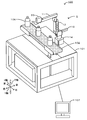
- FIG. 1 is a schematic explanatory diagram of a work execution system 100.
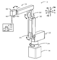
- FIG. 1 is a schematic explanatory diagram of a robot arm 1.
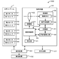
- FIG. 3 is a block diagram showing an electrical connection relationship in the work execution system 100.
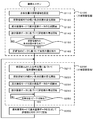
- FIG. The flowchart which shows an example of an imaging routine.
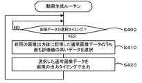
- the flowchart which shows an example of a moving image production
- Explanatory drawing which shows a mode that it searches for a focus position and produces
- FIG. 1 is a schematic explanatory diagram of a work execution system 100 including an imaging device 60 of the present invention.
- FIG. 2 is a schematic explanatory diagram of the robot arm 1.
- FIG. 3 is a block diagram showing an electrical connection relationship in the work execution system 100.
- the left and right direction (X axis), the front and rear direction (Y axis), and the vertical direction (Z axis) of the work execution system 100 are as shown in FIG.
- the robot arm 1 is movable in all directions, there is no specific direction to be fixed. However, for convenience of explanation, the direction shown in FIG. The description will be made with the front-rear direction (Y-axis) and the vertical direction (Z-axis).
- the work execution system 100 is configured as a device that performs a plurality of predetermined work on a work target object (work).
- the work execution system 100 includes a robot arm 1, an imaging device 60 attached to the robot arm 1, a base 101 on which the robot arm 1 is disposed, and a belt conveyor that conveys a bottle 106 that is a workpiece in the present embodiment. , A display device 107, and a control device 80 (see FIG. 3) for controlling the entire device.
- one robot arm 1 is disposed behind the transfer device 102, but the work execution system 100 is disposed at least one of the front or rear of the transfer device 102.
- One or more robot arms 1 may be provided.
- the robot arm 1 is configured as a device that performs predetermined work on a workpiece.
- the workpiece is not particularly limited, and examples thereof include various parts such as mechanical parts, electrical parts, electronic parts, and chemical parts, foods, biotechnology, biological items, and the like.
- the predetermined work includes, for example, a process of collecting, moving, and arranging from an initial position to a predetermined position, a process of deforming, connecting, and joining a predetermined part, or a process of inspecting a workpiece.
- the robot arm 1 performs at least processing for inspecting the appearance of the bottle 106 based on the captured image of the bottle 106 that is a workpiece.
- the robot arm 1 is a multi-axis robot configured as a vertical articulated robot, and includes a first arm 11, a second arm 12, a third support portion 13, a pedestal portion 14, and a tip portion 50. ing.
- the robot arm 1 includes a plurality of (four in this embodiment) first to fourth rotation mechanisms 21 to 24 and a plurality (four in this embodiment) of first to fourth motors 31. 34 and a plurality (four in the present embodiment) of first to fourth encoders 41 to 44 (see FIG. 3).
- the first arm 11 is a longitudinal member provided with a distal end portion 50 that is a working portion that performs work on a workpiece.
- the first arm 11 is connected to the distal end portion 50 via a first rotation mechanism 21 that is disposed at an end opposite to the second arm 12 and has a rotation shaft and a gear mechanism.
- a first motor 31 and a first encoder 41 are housed inside the first arm 11.
- the first motor 31 outputs a rotational driving force to rotate the rotation shaft of the first rotation mechanism 21. Therefore, the distal end portion 50 is disposed so as to be rotatable with respect to the first arm 11.
- the first encoder 41 is attached to the first motor 31 and outputs an encoder signal that is a pulse capable of detecting the rotational position of the first motor 31.
- the second arm 12 is a longitudinal member to which the first arm 11 is connected via a second rotating mechanism 22 having a rotating shaft and a gear mechanism.
- a second motor 32 and a second encoder 42 are housed inside the second arm 12.
- the second motor 32 outputs a rotational driving force to rotate the rotation shaft of the second rotation mechanism 22. Therefore, the first arm 11 is disposed so as to be rotatable with respect to the second arm 12.
- the second encoder 42 is attached to the second motor 32 and outputs an encoder signal that is a pulse capable of detecting the rotational position of the second motor 32.
- the third support portion 13 is a member to which the second arm 12 is connected via a third rotation mechanism 23 having a rotation shaft and a gear mechanism.
- a third motor 33 and a third encoder 43 are housed inside the third support portion 13.
- the third motor 33 outputs a rotational driving force to rotate the rotation shaft of the third rotation mechanism 23. Therefore, the second arm 12 is disposed so as to be rotatable with respect to the third support portion 13.
- the third encoder 43 is attached to the third motor 33 and outputs an encoder signal that is a pulse that can detect the rotational position of the third motor 33.
- the pedestal portion 14 supports the third support portion 13 via a fourth rotation mechanism 24 including a support shaft formed in the vertical direction.
- a fourth motor 34 and a fourth encoder 44 are housed inside the pedestal portion 14.
- the fourth motor 34 outputs a rotational driving force to rotate the support shaft of the fourth rotation mechanism 24. Therefore, the third support portion 13 is disposed so as to be rotatable with respect to the pedestal portion 14.
- the fourth encoder 44 is attached to the fourth motor 34 and outputs an encoder signal that is a pulse capable of detecting the rotational position of the fourth motor 34.
- the tip portion 50 performs a predetermined operation on the workpiece.
- the distal end portion 50 includes a mounting portion 52 and an imaging device 60.
- the mounting portion 52 is disposed on the lower surface of the main body of the distal end portion 50.
- Various members for performing a predetermined work on the workpiece can be mounted on the lower surface of the mounting portion 52.
- a mechanical chuck for gripping the workpiece can be mounted.
- the imaging device 60 is a device that can capture an image.
- the transport device 102 captures the bottle 106 being transported and its periphery.
- the imaging device 60 includes an irradiation unit 61, a variable focus lens 62, a driving unit 63, an imaging unit 64, a storage unit 67, an evaluation value deriving unit 68, and an imaging control unit 69 (see FIG. 3). ).
- the irradiating unit 61 is, for example, illumination arranged in a circular shape on the outer periphery of the variable focus lens 62, and can irradiate the work and the periphery of the work with light.
- the variable focus lens 62 is configured to be movable in the optical axis direction (left-right direction in FIG.
- the drive unit 63 is a mechanism that moves the variable focus lens 62.
- the drive part 63 is good also as a structure provided with the encoder which can detect the rotation position of a motor and a motor, for example.
- the imaging unit 64 is a module that receives light that has passed through the variable focus lens and generates image data, and includes an imaging element 65 and a signal processing unit 66.
- the image sensor 65 receives the light that has passed through the variable focus lens 62 and photoelectrically converts the light to generate a charge corresponding to each pixel.
- the image sensor 65 may be a CMOS image sensor, for example.
- the signal processing unit 66 reads out the electric charges generated by the image sensor 65 and generates image data that is digital data including information on each pixel.
- the imaging unit 64 has a normal imaging mode in which normal image data is generated as image data, and a partial imaging mode in which partial image data corresponding to a partial area of the normal image is generated as image data.
- the signal processing unit 66 reads out all the charges corresponding to the respective pixels generated by the image sensor 65 and generates normal image data. That is, in the present embodiment, the normal image data is an image having the maximum size (number of pixels) that can be generated by the imaging unit 64.
- the signal processing unit 66 reads only the charges corresponding to a part of the charges generated by the image sensor 65 to generate partial image data. Therefore, the partial image data is an image having a smaller number of pixels than the normal image data.
- the partial image data is image data corresponding to an image obtained by cutting out the pixel in the central rectangular area from the normal image data (see partial image data S1 to S3 in FIG. 6 described later).
- the number of pixels of the partial image data may be, for example, 1/3 to 1/10 of the normal image data.
- the storage unit 67 can store various data such as the image data generated by the signal processing unit 66 and the evaluation value derived by the evaluation value deriving unit 68.
- the evaluation value deriving unit 68 derives an evaluation value representing the degree of focus of the subject in the image data based on the image data generated by the imaging unit 64.
- the evaluation value deriving unit 68 derives the contrast of the subject based on the luminance information of the image data, and derives the evaluation value based on this contrast.
- the imaging control unit 69 controls the entire imaging device 60.
- the imaging control unit 69 outputs a control signal to the irradiating unit 61 to control light irradiation from the irradiating unit 61, outputs a control signal to the imaging unit 64 to take an image, or derives an evaluation value.
- An evaluation value is derived by outputting a control signal to the unit 68.
- the imaging control unit 69 outputs a control signal to the driving unit 63 to change the focal position of the variable focus lens 62, or inputs a signal from the encoder of the driving unit 63 to change the focal position of the variable focus lens 62. Or detect.
- the imaging control unit 69 outputs a plurality of image data generated by the imaging unit 64 as moving images to the control device 80 and the display device 107, and inputs a command from the control device 80.
- each of the signal processing unit 66, the evaluation value deriving unit 68, and the imaging control unit 69 is configured by a hardware circuit as a dedicated processing circuit. However, one or more of these may be realized by software such as a program executed on the CPU of the imaging device 60.
- the control device 80 is configured as a microprocessor centered on a CPU, and controls the entire device of the work execution system 100.
- the control device 80 outputs signals to the first to fourth motors 31 to 34, the imaging device 60, and the transport device 102. Also, the control device 80 receives encoder signals from the first to fourth encoders 41 to 44 and a moving image from the imaging device 60.
- the display device 107 is configured as a device such as a liquid crystal display, and displays information to the worker of the work execution system 100, for example.
- the display device 107 displays the moving image input from the imaging device 60.
- the display device 107 may include a storage unit that stores a moving image input from the imaging device 60.
- the control device 80 controls the first to fourth motors 31 to 34 of the robot arm 1 to move the imaging device 60 to a position where the bottle 106 conveyed by the conveying device 102 can be imaged.
- An imaging start command is output.
- the imaging device 60 that has input the imaging start command images the bottle 106 and continuously outputs a plurality of normal image data including the bottle 106 to the control device 80 and the display device 107.
- the imaging device 60 outputs a moving image to the control device 80 and the display device 107.
- the control device 80 recognizes the position, moving direction, moving speed, and the like of the bottle 106 based on a plurality of normal image data included in the input moving image, tracks the bottle 106, and the imaging device 60 moves the bottle 106 from a plurality of directions.
- the robot arm 1 is controlled so as to take an image.
- the control device 80 performs an appearance inspection for inspecting the presence or absence of an abnormality in the appearance of the bottle 106 based on a plurality of normal image data included in the input moving image.
- the operator confirms the moving image displayed on the display device 107 as necessary, and confirms the visual inspection of the bottle 106 and the presence or absence of abnormal operation of the imaging device 60 and the control device 80.
- the control device 80 controls the robot arm 1 to continue moving the imaging device 60 to a position where the normal image data necessary for the appearance inspection can be captured in the bottle 106, and the imaging device 60 generates a moving image during that time. Keep doing.
- an operation when the imaging device 60 that has input the imaging start command outputs a moving image to the control device 80 and the display device 107 will be described in detail.
- FIG. 4 is a flowchart illustrating an example of an imaging routine.
- FIG. 5 is a flowchart illustrating an example of the moving image generation routine.
- FIG. 6 is an explanatory diagram showing a state in which the in-focus position is searched and a moving image is generated while switching between the partial imaging mode and the normal imaging mode.
- the horizontal axis is time t, and the polygonal line shown at the top indicates the time change of the focal position of the variable focus lens 62.
- the curve shown in the second row shows the time change of the evaluation value derived by the focus position search process (here, the global search and the small area search) described later.
- the thick line shown in the third row indicates the time change of the imaging mode
- the thick broken line indicates the partial imaging mode
- the thick solid line indicates the normal imaging mode.
- the fourth row shows the output timing of individual normal image data constituting a moving image.
- the bottom row shows partial image data S1 to S3 and normal image data P1.
- the imaging control unit 69 When the imaging control unit 69 inputs an imaging start command from the control device 80, the imaging control unit 69 starts the routine of FIGS. First, the imaging routine of FIG. 4 will be described.
- the imaging control unit 69 first performs a global search process, which is a process for searching for a focus position that is a focus position of the variable focus lens 62 from which the subject is focused (step S100).
- the imaging control unit 69 first sets a search area that is an area in which the focal position of the variable focus lens 62 is changed (step S110). For example, the search area A1 is set at time t0 as shown in FIG.
- This search area A1 is set as a larger area than the search areas A2 to A6 of the small area search process (S200) described later.
- the search area A1 extends from the upper limit to the lower limit of the focal position at which the variable focus lens 62 can change. All areas are set.
- the imaging control unit 69 controls the drive unit 63 so as to start a process of roughly changing the focal position of the variable focus lens 62 within the search region set in step S100 (step S120).
- the drive unit 63 sequentially changes the focal position of the variable focus lens 62 so as to be relatively rough, that is, the change width per unit time is relatively large from one end side to the other end side of the set search region, for example. Change it.
- the imaging control unit 69 controls the imaging unit 64 to start generating partial image data in the partial imaging mode (step S130). Accordingly, the imaging unit 64 continuously generates partial image data in the partial imaging mode, and sequentially stores the partial image data in the storage unit 67. Subsequently, the imaging control unit 69 controls the evaluation value deriving unit 68 to start derivation of the evaluation value based on the partial image data stored in the storage unit 67 (step S140). Accordingly, when new partial image data is stored in the storage unit 67, the evaluation value deriving unit 68 derives an evaluation value based on the new partial image data and stores the evaluation value in the storage unit 67.
- the imaging control unit 69 When the imaging control unit 69 performs steps S120 to S140, while the drive unit 63 changes the focal position of the variable focus lens 62 within the search area A1, as shown at times t0 to t1 in FIG.
- the imaging unit 64 continuously generates partial image data, and the evaluation value deriving unit 68 sequentially derives the evaluation values of the generated partial image data, and these partial image data and evaluation values are stored in the storage unit 67. It will be done.
- the focal position, the partial image data, and the evaluation value of the variable focus lens 62 are stored in the storage unit 67 in association with each other through information representing time, for example.
- the imaging control unit 69 waits until the change of the focal position from one end side to the other end side in the search region set in step S110 is completed (step S150). That is, the imaging control unit 69 waits until the search in the search area is completed.
- the imaging control unit 69 detects the in-focus position based on the derived evaluation value peak and stores it in the storage unit 67 (step S160), and ends the global search process. For example, in the global search process between times t0 and t1 in FIG. 6, since the peak of the evaluation value is the value V1, the focal position L1 when the value V1 is obtained is stored in the storage unit 67 as the in-focus position. To do.
- the imaging control unit 69 performs the small area search process (step S200).
- the small area search process is the same as the large area search process except that the search area to be set is small, the change in the focal position of the variable focus lens 62 is fine, and the process is terminated when a peak of the evaluation value is detected. Perform the process.
- the imaging control unit 69 first sets a search area in a range smaller than the search area in the global search process based on the focus position detected last time (step S210). Therefore, in the small area search process executed after the global search process, a search area is set based on the in-focus position detected in step S160 of the immediately preceding global search process. In the present embodiment, as illustrated in FIG.
- the imaging control unit 69 sets a predetermined range centered on the detected focus position (focal position L1) as the next search area A2. Subsequently, the imaging control unit 69 performs processing for finely changing the focal position within the set search region (step S220), processing for starting generation of partial image data (step S230), and processing for deriving an evaluation value. (Step S240) is started by the driving unit 63, the imaging unit 64, and the evaluation value deriving unit 68, respectively.
- the processing in steps S220 to S240 is the same as the processing in step S220 except that the focal position of the variable focus lens 62 is sequentially changed so as to be relatively finer, that is, the change width per unit time is relatively smaller than that in step S120. This is the same as steps S120 to S140.
- the imaging control unit 69 waits until the peak of the evaluation value, that is, the in-focus position is detected (step S250), and when the in-focus position is detected, the small area search process is terminated.
- the imaging control unit 69 can detect the peak of the evaluation value depending on, for example, whether or not the evaluation value sequentially derived exceeds the peak. For example, in the small area search process between time t1 and time t2 in FIG. 6, when a value V3 that decreases after the evaluation value has increased to the value V2 with time has been derived, the value V2 is the peak of the evaluation value. It is detected that the focus position L2 is the in-focus position.
- the imaging control unit 69 determines that the derived evaluation value has exceeded the peak when the derived evaluation value continuously decreases for a plurality of times (for example, two times) in order to increase the accuracy of peak detection, or the derived evaluation value. Alternatively, it may be determined that the peak has been exceeded when the value falls below a predetermined change width.
- the imaging control unit 69 stores the detected focus position in the storage unit 67.
- the imaging control unit 69 performs normal image data generation processing for controlling the imaging unit 64 to generate normal image data in the normal imaging mode, and uses the generated normal image data. It associates with the evaluation value and stores it in the storage unit 67 (step S300). Thereby, normal image data at the focal position based on the in-focus position detected in step S250 of the immediately preceding small area search process is generated.
- the imaging control unit 69 controls the drive unit 63 to stop the change of the focal position when it is determined in step S250 that the in-focus position has been detected, and normal image data generation processing is performed in that state. Do. For example, in the small area search process between time t1 and time t2 in FIG.
- the focus position (focus position L2) is detected when the focus position of the variable focus lens 62 is at the focus position L3.
- normal image data P1 is generated between times t2 and t3.
- the imaging control unit 69 controls the drive unit 63 to stop the change of the focal position when it is determined in step S250 that the in-focus position has been detected. Normal image data generation processing may be performed in a changed state.
- the imaging control unit 69 stores the generated normal image data and the evaluation value in association with each other.
- the evaluation value is a value derived by the evaluation value deriving unit 68 based on the normal image data.
- it may be a value that can be regarded as an evaluation value of normal image data.
- Values that can be regarded as evaluation values of normal image data include an evaluation value corresponding to the focus position detected immediately before (for example, value V2 corresponding to the focus position L2 in FIG. 6), and the focus when the focus position is detected. And an evaluation value corresponding to the position (for example, a value V3 corresponding to the focal position L3 in FIG. 6).
- the imaging control unit 69 regards the evaluation value corresponding to the focal position when the in-focus position is detected, in other words, the evaluation value derived immediately before as the evaluation value of the normal image data.
- the values and the normal image data are stored in the storage unit 67 in association with each other.
- the imaging control unit 69 sets a relatively large search area in the global search process in step S100 to detect a rough focus position, and then detects a relatively small search area in the small area search process in step S200. Is set to detect a detailed in-focus position, and normal image data at a focal position near the detected in-focus position is generated.
- the imaging unit 64 performs imaging in the partial imaging mode, and performs imaging in the normal imaging mode only after the in-focus position is detected in the small area searching process. Therefore, in the partial imaging mode, for example, as shown in the lowermost stage of FIG. 6, the imaging unit 64 generates only partial image data S1 corresponding to a part of the normal image data P.
- the global search process and the small area search process are processes for searching for an in-focus position
- the partial image data generated during these processes includes an image that is not in focus, that is, an out-of-focus image. Images are also included (for example, partial image data S1 and S2 in FIG. 6).
- step S300 the imaging control unit 69 executes the processing after step S200. That is, the small area search process in step S200 and the process of generating and storing normal image data in step S300 are repeated.
- a plurality of small area search processes (from time t3 to t4, from time t5 to t6, from time t7 to t8, etc
- Image data generation processing (between times t4 and t5, between times t6 and t7, between times t8 and t9,...) Is performed alternately to generate a plurality of normal image data (P2, P3, P4,). Is generated.
- the imaging control unit 69 sets the search area based on the in-focus position detected in the previous small area search process. For example, in FIG. 6, the imaging control unit 69 sets the search area A3 as a range centered on the focal position L2 based on the in-focus position (focal position L2) at time t3.
- the processes after the second small area search process in FIG. 6, the search areas A4 to A6, the focal positions L4 to L9, and the evaluation value values V4 to V9 are the processes (small areas) described above. Since the content is the same as the area search process and the process similar to step S300), detailed description thereof is omitted. Note that, as described above, the robot arm 1 is controlled by the control device 80 to move and the bottle 106 also moves, so that the in-focus position changes with the passage of time.
- This moving image generation routine is executed in parallel with the imaging routine of FIG.
- the moving image generation routine is processing for generating a moving image based on the normal image data stored in the storage unit 67 in the imaging routine of FIG. 4 and outputting the generated moving image to the control device 80 and the display device 107.
- the imaging control unit 69 first waits until image data selection timing comes (step S400).
- the selection timing of the image data may be set immediately before the output timing of the image data to the control device 80 and the display device 107, for example.
- the imaging control unit 69 starts outputting image data every time the output period Tf of the image for one frame of the moving image elapses with reference to the time t0 when the routines of FIGS. For example, in FIG. 6, the time T1 when the output cycle Tf has elapsed from the time t0 and the time T2 when the output cycle Tf has elapsed are the output timing of the image data. For this reason, the time immediately before the times T1 and T2 is set as the selection timing. If it is determined in step S400 that the image data is selected, the imaging control unit 69 selects data having the highest evaluation value from the normal image data stored in the storage unit 67 after the previous image data output (step S410). The normal image data thus output is output at the output timing of the image data (step S420), and the processing after step S400 is executed.
- the imaging control unit 69 selects the normal image data P1, and starts output to the control device 80 and the display device 107 at time T1.
- the imaging control unit 69 has the higher evaluation value (value V5> V7). Normal image data P2 is selected. Then, the imaging control unit 69 starts outputting the normal image data P2 to the control device 80 and the display device 107 at time T2.
- the imaging control unit 69 outputs the normal image data one by one every time the output cycle Tf of the image for one frame elapses, so that the predetermined frame rate (1 frame / output cycle Tf) is output. ).
- the imaging control unit 69 selects and outputs normal image data having a higher corresponding evaluation value.
- the frame rate of the moving image to be output may be specified by the control device 80, for example.
- the imaging control unit 69 of the imaging device 60 causes the imaging unit 64 to generate partial image data in the partial imaging mode, and the evaluation value deriving unit 68 sends the evaluation value of the partial image data.
- the deriving process is performed a plurality of times while changing the focal position of the varifocal lens 62, and the in-focus position search process for detecting the in-focus position, which is the in-focus position based on the derived plurality of evaluation values. (Here, the global search process and the small area search process) are performed.
- the imaging control unit 69 performs normal image data generation processing (step S300) that causes the imaging unit 64 to generate normal image data in the normal imaging mode at the focal position based on the detected in-focus position. Since the partial image data has a smaller data amount than the normal image data, the in-focus position search process can be performed in a shorter time compared to the case of using a plurality of normal image data in the in-focus position search process. When the in-focus position is detected, normal image data generation processing is performed, so that normal image data in focus can be obtained. As described above, focused image data (normal image data) can be obtained in a shorter time.
- the imaging control unit 69 sets a search area, which is an area for changing the focal position of the varifocal lens 62, as a focus position search process, and a global search process for roughly searching the focus position, and a global search process.
- a small area search process is performed in which the focal position of the varifocal lens 62 is set more finely than the global search process in a search area that is set based on the detected focus position and is smaller than the global search process. Then, the imaging control unit 69 performs normal image data generation processing based on the in-focus position detected in the small area search processing.
- the focal position of the variable focus lens 62 is changed in the search area having a smaller range compared to the global search process, and therefore the focus position search process is performed in a shorter time. be able to. For example, it is possible to search for a detailed in-focus position in a shorter time than when the focus position is changed finely in the global search process without performing the small area search process. As a result, focused normal image data can be obtained in a shorter time.
- the small area search process since the search area is set based on the focus position detected in the global search process, the focus position can be appropriately detected even if the search area is reduced.
- the imaging control unit 69 when the imaging control unit 69 repeatedly performs the small area search process after performing the global search process, in the small area search process next to the global search process, the search area is set to the in-focus position detected by the global search process. Set based on.
- the imaging control unit 69 sets the search area based on the in-focus position detected in the previous small area search process in the small area search process subsequent to the small area search.
- the search area is set based on the in-focus position detected in the previous small area search process.
- the second and subsequent small area search processes are also detected in the global search process. As compared with the case where the search area is set based on the in-focus position, it is easy to set an appropriate search area even when the focus position changes over time.
- the imaging control unit 69 determines whether or not the evaluation value exceeds the peak based on the plurality of derived evaluation values, and detects the in-focus position when it exceeds the peak. Therefore, normal image data generation processing is performed without returning the focal position of the variable focus lens 62 to the peak side when the peak is exceeded. As a result, normal image data can be obtained in a shorter time than when normal image data generation processing is performed after the focal position of the variable focus lens 62 is returned to the peak side when the evaluation value exceeds the peak. it can. Note that there is a slight shift in the focal position between when the evaluation value is at the peak and when the evaluation value exceeds the peak. Therefore, even if normal image data generation processing is performed when the evaluation value exceeds the peak, the image is sufficiently focused. Normal image data is obtained.
- the imaging control unit 69 repeatedly performs the focus position search process and the normal image data generation process to generate a moving image based on the obtained plurality of normal image data. Accordingly, since the image data (partial image data in this embodiment) during the in-focus position search process is not included in the moving image, each of the images included in the moving image is an in-focus image. An out-of-focus image may cause false detection or false detection of the appearance inspection of the bottle 106 by the control device 80, but this can be reduced. In addition, when an operator confirms a moving image displayed on the display device 107, an image that is out of focus is included, but there is a sense of incongruity, but this can be reduced.
- the imaging apparatus 60 that can generate normal image data has a relatively long period. Even in such a case, it is easy to generate normal image data that is in focus at the required output cycle Tf.
- the small area search process is repeatedly performed after the global search process.
- the present invention is not limited thereto, and any apparatus that performs the focus position search process may be used.
- normal image data may be generated based on the in-focus position detected in the global search process without performing the small area search process.
- the imaging control unit 69 waits until the change of the focal position in the search area is completed in step S150 of the global search process.
- the present invention is not limited to this, and is evaluated in the same manner as in step S250 of the small area search process. If a value peak is detected, the process may proceed to step S160.
- the normal image data based on the in-focus position detected in the global search process is not generated, but may be generated.
- the imaging control unit 69 sets the search area based on the focus position detected in the previous small area search process in the small area search process subsequent to the small area search. I can't.
- the search range may be set based on the in-focus position detected in the most recent global search process also in the small area search process subsequent to the small area search.
- the imaging control unit 69 performs the normal image data generation processing in step S300 without returning the focal position of the variable focus lens 62 to the peak side when the evaluation value exceeds the peak. You may return to.
- the imaging control unit 69 may control the driving unit 63 to move the focal position from L3 to L2, and cause the imaging unit 64 to generate normal image data at the focal position L2.
- the imaging control unit 69 outputs a plurality of normal image data as a moving image, that is, with a predetermined output cycle Tf, but is not limited thereto.
- each of the plurality of normal image data obtained in step S300 may be sequentially output as an image file.
- the imaging control unit 69 outputs the normal image data to the control device 80 and the display device 107.
- the imaging control unit 69 may output the normal image data to any one of these, or may output to other devices.
- the data may be stored in the storage unit 67 without being output.
- the imaging device 60 is disposed at the distal end portion 50 of the robot arm 1, but the present invention is not limited to this.
- the imaging device 60 may be fixedly arranged at a position where the bottle 106 can be imaged.
- the controller 80 controls the robot arm 1 to perform the appearance inspection of the bottle 106 that is a workpiece
- the present invention is not limited thereto.
- the control device 80 collects and moves a workpiece using a sampling member such as a mechanical chuck mounted on the mounting portion 52 of the robot arm 1, and the imaging device 60 uses the normal image for recognition of the workpiece at this time. Data may be generated.
- the work execution system 100 including the robot arm 1, the imaging device 60, the control device 80, and the display device 107 has been described.
- the control device 80 and the imaging device 60 connected to the robot arm 1 are provided. It is good also as an imaging system provided, and it is good also as an imaging system provided with the display apparatus 107 in addition to or instead of the control apparatus 80. Further, the imaging device 60 alone connected to the robot arm 1 may be used.
- the present invention can be used in the technical field of an apparatus that performs processing such as visual inspection of a workpiece.
Landscapes
- Engineering & Computer Science (AREA)
- Multimedia (AREA)
- Signal Processing (AREA)
- Studio Devices (AREA)
Abstract
撮像装置の撮像制御部は、時刻t1~t2において、撮像部に部分画像データ(S1,S2,S3,・・・)を生成させ部分画像データの評価値を評価値導出部に導出させる処理を可変焦点レンズの焦点位置を変化させながら複数回行って、導出された複数の評価値に基づいて合焦が得られる焦点位置である合焦位置(焦点位置L2)を検出する小域探索処理を行う。そして、時刻t2~t3において、撮像制御部は、検出された合焦位置(焦点位置L2)に基づく焦点位置L3において撮像部に通常画像データP1を生成させる通常画像データ生成処理を行う。
Description
本発明は、撮像装置に関する。
従来、撮像装置としては、1フィールド期間内に複数供給される画像データのうち、最大コントラスト値が得られる画像データを選択してモニター系に映出するものが知られている(特許文献1)。特許文献1では、これにより、ピントのボケない安定した映像のみを出力できるとしている。
しかし、特許文献1に記載の撮像装置では、目的とする画像(最大コントラスト値が得られる画像)を得るために複数の画像を撮像する必要があり、目的とする画像を得るまでに時間がかかるという問題があった。
本発明は、上述した課題を解決するためになされたものであり、ピントの合った画像データをより短時間で得ることを主目的とする。
本発明は、上述した主目的を達成するために以下の手段を採った。
本発明の撮像装置は、
可変焦点レンズと、
前記可変焦点レンズを通過した光を受光して画像データを生成する撮像部であって、該画像データとして通常画像データを生成する通常撮像モードと、該画像データとして該通常画像の一部の領域に相当する部分画像データを生成する部分撮像モードと、を有する撮像部と、
前記撮像部が生成した画像データに基づいて該画像データの合焦度合いを表す評価値を導出する評価値導出部と、
前記撮像部に前記部分撮像モードで前記部分画像データを生成させ該部分画像データの前記評価値を前記評価値導出部に導出させる処理を前記可変焦点レンズの焦点位置を変化させながら複数回行って、該導出された複数の評価値に基づいて合焦が得られる焦点位置である合焦位置を検出する合焦位置探索処理と、該検出された合焦位置に基づく焦点位置において前記撮像部に前記通常撮像モードで前記通常画像データを生成させる通常画像データ生成処理と、を行う撮像制御部と、
を備えたものである。
可変焦点レンズと、
前記可変焦点レンズを通過した光を受光して画像データを生成する撮像部であって、該画像データとして通常画像データを生成する通常撮像モードと、該画像データとして該通常画像の一部の領域に相当する部分画像データを生成する部分撮像モードと、を有する撮像部と、
前記撮像部が生成した画像データに基づいて該画像データの合焦度合いを表す評価値を導出する評価値導出部と、
前記撮像部に前記部分撮像モードで前記部分画像データを生成させ該部分画像データの前記評価値を前記評価値導出部に導出させる処理を前記可変焦点レンズの焦点位置を変化させながら複数回行って、該導出された複数の評価値に基づいて合焦が得られる焦点位置である合焦位置を検出する合焦位置探索処理と、該検出された合焦位置に基づく焦点位置において前記撮像部に前記通常撮像モードで前記通常画像データを生成させる通常画像データ生成処理と、を行う撮像制御部と、
を備えたものである。
この撮像装置では、合焦位置探索処理では複数の部分画像データに基づく処理を行って合焦位置を検出する。こうすれば、部分画像データは通常画像データと比べてデータ量が小さいため、合焦位置探索処理において複数の通常画像データを用いる場合と比較して短時間で合焦位置探索処理を行うことができる。そして、合焦位置が検出された場合には通常画像データ生成処理を行うから、ピントの合った通常画像データが得られる。以上により、ピントの合った画像データ(通常画像データ)をより短時間で得ることができる。
本発明の実施形態を図面を参照しながら以下に説明する。図1は、本発明の撮像装置60を備えた作業実行システム100の概略説明図である。図2は、ロボットアーム1の概略説明図である。図3は、作業実行システム100における電気的な接続関係を表すブロック図である。なお、作業実行システム100の左右方向(X軸)、前後方向(Y軸)及び上下方向(Z軸)は、図1に示した通りとする。また、ロボットアーム1は全方位に可動するため固定される特定の方向はないが、説明の便宜のため、ロボットアーム1に対しては、図2に示した方向を左右方向(X軸)、前後方向(Y軸)及び上下方向(Z軸)として説明する。
作業実行システム100は、作業対象の物品(ワーク)に対して複数の所定の作業を行う装置として構成されている。作業実行システム100は、ロボットアーム1と、ロボットアーム1に取り付けられた撮像装置60と、ロボットアーム1が配設される基台101と、本実施形態におけるワークであるボトル106を搬送するベルトコンベアとして構成された搬送装置102と、表示装置107と、装置全体を制御する制御装置80(図3参照)と、を備えている。なお、本実施形態では、図1に示すようにロボットアーム1が搬送装置102の後方に1つ配設されているが、作業実行システム100は搬送装置102の前方又は後方の少なくとも一方に配設された1以上のロボットアーム1を他にも備えていてもよい。
ロボットアーム1は、ワークに対して所定の作業を行う装置として構成されている。ワークは、特に限定されないが、例えば、機械部品、電気部品、電子部品、化学部品など各種の部品のほか、食品、バイオ、生物関連の物品などが挙げられる。また、所定の作業としては、例えば、初期位置から所定位置まで採取、移動、配置する処理や、所定の部位に対して変形、接続、接合させる処理、又はワークを検査する処理などが挙げられる。本実施形態では、ロボットアーム1は、少なくとも、ワークであるボトル106を撮像し撮像された画像に基づいてボトル106の外観を検査する処理を行う。
ロボットアーム1は、垂直多関節ロボットとして構成された多軸ロボットであり、第1アーム11と、第2アーム12と、第3支持部13と、台座部14と、先端部50と、を備えている。また、ロボットアーム1は、複数(本実施形態では4個)の回転機構である第1~第4回転機構21~24と、複数(本実施形態では4個)の第1~第4モータ31~34と、複数(本実施形態では4個)の第1~第4エンコーダ41~44と、を備えている(図3参照)。
第1アーム11は、図2に示すように、ワークに対して作業を行う作業部である先端部50が配設された長手部材である。第1アーム11は、第2アーム12とは反対側の端部に配設され回転軸及び歯車機構を有する第1回転機構21を介して、先端部50と接続されている。第1アーム11の内部には、第1モータ31及び第1エンコーダ41が収納されている。第1モータ31は、回転駆動力を出力して第1回転機構21の回転軸を回転させる。そのため、先端部50は第1アーム11に対して回動可能に配設されている。第1エンコーダ41は、第1モータ31に取り付けられており、第1モータ31の回転位置を検出可能なパルスであるエンコーダ信号を出力する。
第2アーム12は、回転軸及び歯車機構を有する第2回転機構22を介して第1アーム11が接続された長手部材である。第2アーム12の内部には、第2モータ32及び第2エンコーダ42が収納されている。第2モータ32は、回転駆動力を出力して第2回転機構22の回転軸を回転させる。そのため、第1アーム11は第2アーム12に対して回動可能に配設されている。第2エンコーダ42は、第2モータ32に取り付けられており、第2モータ32の回転位置を検出可能なパルスであるエンコーダ信号を出力する。
第3支持部13は、回転軸及び歯車機構を有する第3回転機構23を介して第2アーム12が接続された部材である。第3支持部13の内部には、第3モータ33及び第3エンコーダ43が収納されている。第3モータ33は、回転駆動力を出力して第3回転機構23の回転軸を回転させる。そのため、第2アーム12は第3支持部13に対して回動可能に配設されている。第3エンコーダ43は、第3モータ33に取り付けられており、第3モータ33の回転位置を検出可能なパルスであるエンコーダ信号を出力する。
台座部14は、上下方向に形成された支持軸を含む第4回転機構24を介して第3支持部13を支持する。台座部14の内部には、第4モータ34及び第4エンコーダ44が収納されている。第4モータ34は、回転駆動力を出力して第4回転機構24の支持軸を回転させる。そのため、第3支持部13は台座部14に対して回動可能に配設されている。第4エンコーダ44は、第4モータ34に取り付けられており、第4モータ34の回転位置を検出可能なパルスであるエンコーダ信号を出力する。
先端部50は、ワークに対して所定の作業を行うものである。先端部50は、図2に示すように、装着部52と、撮像装置60と、を備えている。装着部52は、先端部50本体の下面に配設されている。装着部52の下面には、ワークに対して所定の作業を行うための種々の部材を装着可能であり、例えばワークを把持するメカニカルチャックなどを装着可能である。
撮像装置60は、画像を撮像可能な装置であり、例えば搬送装置102によって搬送中のボトル106及びその周辺を撮像する。撮像装置60は、照射部61と、可変焦点レンズ62と、駆動部63と、撮像部64と、記憶部67と、評価値導出部68と、撮像制御部69と、を備える(図3参照)。照射部61は、例えば、可変焦点レンズ62の外周に円状に配設された照明であり、ワーク及びワークの周辺に対して光を照射可能である。可変焦点レンズ62は、駆動部63により移動することで光軸方向(図3の左右方向)に移動可能に構成されており、これにより焦点位置が変更可能である。駆動部63は、可変焦点レンズ62を移動させる機構である。駆動部63は、例えばモータとモータの回転位置を検出可能なエンコーダとを備えた構成としてもよい。
撮像部64は、可変焦点レンズを通過した光を受光して画像データを生成するモジュールであり、撮像素子65と、信号処理部66と、を備えている。撮像素子65は、可変焦点レンズ62を通過した光を受光しその光を光電変換して各々の画素に対応する電荷を生成する。撮像素子65は、例えばCMOSイメージセンサとしてもよい。信号処理部66は、撮像素子65で生成された電荷を読み出して各々の画素の情報を含むデジタルデータである画像データを生成する。撮像部64は、画像データとして通常画像データを生成する通常撮像モードと、画像データとして通常画像の一部の領域に相当する部分画像データを生成する部分撮像モードと、を有する。本実施形態において、通常撮像モードでは、撮像素子65が生成した各々の画素に対応する電荷を全て信号処理部66が読み出して通常画像データを生成する。すなわち、本実施形態では、通常画像データは撮像部64が生成可能な最大の大きさ(画素数)の画像とした。一方、本実施形態において、部分撮像モードでは、撮像素子65が生成した電荷のうち一部の領域に相当する電荷のみを信号処理部66が読み出して部分画像データを生成する。そのため、部分画像データは、通常画像データよりも画素数の小さい画像となる。本実施形態では、部分画像データは、通常画像データのうち中央の矩形の領域の画素を切り出した画像に相当する画像データとした(後述する図6の部分画像データS1~S3参照)。部分画像データの画素数は、例えば通常画像データの1/3~1/10の画素数としてもよい。
記憶部67は、信号処理部66で生成された画像データや、評価値導出部68が導出した評価値などの各種データを記憶可能である。評価値導出部68は、撮像部64が生成した画像データに基づいて、画像データにおける被写体の合焦度合いを表す評価値を導出する。本実施形態では、評価値導出部68は、画像データの輝度情報に基づいて被写体のコントラストを導出し、このコントラストに基づいて評価値を導出するものとした。
撮像制御部69は、撮像装置60全体を制御するものである。撮像制御部69は、照射部61に制御信号を出力して照射部61からの光の照射を制御したり、撮像部64に制御信号を出力して画像の撮像を行わせたり、評価値導出部68に制御信号を出力して評価値の導出を行わせたりする。また、撮像制御部69は、駆動部63に制御信号を出力して可変焦点レンズ62の焦点位置を変化させたり、駆動部63のエンコーダからの信号を入力して可変焦点レンズ62の焦点位置を検出したりする。撮像制御部69は、撮像部64が生成した複数の画像データを動画として制御装置80及び表示装置107に出力したり、制御装置80からの指令を入力したりする。
なお、本実施形態では、信号処理部66,評価値導出部68,及び撮像制御部69の各々は、専用の処理回路としてのハードウェア回路で構成されているものとした。ただし、これらの1以上について、撮像装置60が有するCPU上で実行されるプログラムなどのソフトウェアで実現してもよい。
制御装置80は、CPUを中心とするマイクロプロセッサとして構成されており、作業実行システム100の装置全体を制御する。この制御装置80は、第1~第4モータ31~34,撮像装置60,及び搬送装置102へ信号を出力する。また、制御装置80には、第1~第4エンコーダ41~44からのエンコーダ信号や、撮像装置60からの動画が入力される。
表示装置107は、液晶ディスプレイなどの装置として構成されており、例えば作業実行システム100の作業者に情報を表示する。表示装置107は、撮像装置60から入力した動画を表示する。表示装置107は、撮像装置60から入力した動画を記憶する記憶部を有していてもよい。
次に、こうして構成された本実施形態の作業実行システム100の動作、特に、撮像装置60により撮像されたボトル106の画像データに基づいてボトル106の外観を検査する処理について説明する。まず、外観検査の概略について説明する。制御装置80は、まず、ロボットアーム1の第1~第4モータ31~34を制御して、搬送装置102により搬送されるボトル106を撮像可能な位置まで撮像装置60を移動させ、撮像装置60に撮像開始指令を出力する。撮像開始指令を入力した撮像装置60は、ボトル106を撮像してボトル106を含む複数の通常画像データを継続的に制御装置80及び表示装置107に出力する。すなわち、撮像装置60は制御装置80及び表示装置107に動画を出力する。制御装置80は、入力した動画に含まれる複数の通常画像データに基づいてボトル106の位置,移動方向,移動速度などを認識し、ボトル106を追跡して撮像装置60が複数の向きからボトル106を撮像するようロボットアーム1を制御する。また、制御装置80は、入力した動画に含まれる複数の通常画像データに基づいてボトル106の外観の異常の有無を検査する外観検査を行う。また、作業者は、必要に応じて表示装置107に表示された動画を確認して、目視でのボトル106の外観検査や撮像装置60及び制御装置80の動作異常の有無などを確認する。このように、制御装置80はロボットアーム1を制御してボトル106のうち外観検査に必要な通常画像データを撮像可能な位置に撮像装置60を移動させ続け、撮像装置60はその間に動画を生成し続ける。以下、撮像開始指令を入力した撮像装置60が制御装置80及び表示装置107に動画を出力する際の動作について詳細に説明する。
図4は、撮像ルーチンの一例を示すフローチャートである。図5は、動画生成ルーチンの一例を示すフローチャートである。図6は、部分撮像モードと通常撮像モードを切り替えながら合焦位置の探索と動画の生成とを行う様子を示す説明図である。図6では、横軸が時刻tであり、最上段に示す折れ線は可変焦点レンズ62の焦点位置の時間変化を示している。また、2段目に示す曲線は後述する合焦位置探索処理(ここでは大域探索及び小域探索)で導出される評価値の時間変化を示している。3段目に示す太線は撮像モードの時間変化を示しており、太破線が部分撮像モード、太実線が通常撮像モードを表している。4段目は、動画を構成する個々の通常画像データの出力タイミングを示している。最下段は、部分画像データS1~S3と、通常画像データP1とを示している。
撮像制御部69は、制御装置80から撮像開始指令を入力すると、図4,5のルーチンを開始する。まず図4の撮像ルーチンについて説明する。この撮像ルーチンを開始すると、撮像制御部69は、まず、被写体の合焦が得られる可変焦点レンズ62の焦点位置である合焦位置を探索する処理である大域探索処理を行う(ステップS100)。大域探索処理では、撮像制御部69は、まず、可変焦点レンズ62の焦点位置を変化させる領域である探索領域を設定する(ステップS110)。例えば、図6のように時刻t0で探索領域A1を設定する。この探索領域A1は、後述する小域探索処理(S200)の探索領域A2~A6に比して大きい領域として設定されており、例えば可変焦点レンズ62が変化可能な焦点位置の上限から下限までの全ての領域として設定されている。続いて、撮像制御部69は、ステップS100で設定した探索領域内で可変焦点レンズ62の焦点位置を粗く変化させる処理を開始するよう駆動部63を制御する(ステップS120)。これにより、駆動部63は、例えば設定した探索領域の一端側から他端側に向けて、比較的粗くすなわち単位時間当たりの変化幅が比較的大きくなるように可変焦点レンズ62の焦点位置を順次変化させていく。また、撮像制御部69は、部分撮像モードで部分画像データの生成を開始するよう撮像部64を制御する(ステップS130)。これにより、撮像部64は、部分撮像モードで連続的に部分画像データの生成を行って、記憶部67に部分画像データを順次記憶していく。続いて、撮像制御部69は、記憶部67に記憶された部分画像データに基づいて評価値の導出を開始するよう評価値導出部68を制御する(ステップS140)。これにより、評価値導出部68は、記憶部67に新たな部分画像データが記憶されると、それに基づく評価値を導出して記憶部67に記憶する。撮像制御部69がこのステップS120~S140を行うことで、図6の時刻t0~t1に示すように、駆動部63が可変焦点レンズ62の焦点位置を探索領域A1内で変化させている間、撮像部64は連続的に部分画像データを生成し、評価値導出部68は生成された部分画像データの評価値を順次導出していき、これらの部分画像データや評価値が記憶部67に記憶されていく。なお、可変焦点レンズ62の焦点位置,部分画像データ,及び評価値は、例えば時刻を表す情報などを介して互いに対応づけられて記憶部67に記憶されるものとした。
続いて、撮像制御部69は、ステップS110で設定した探索領域内の一端側から他端側までの焦点位置の変化が完了するまで待つ(ステップS150)。すなわち撮像制御部69は探索領域内の探索が完了するまで待つ。焦点位置の変化が完了すると、撮像制御部69は、導出された評価値のピークに基づいて合焦位置を検出し記憶部67に記憶し(ステップS160)、大域探索処理を終了する。例えば、図6の時刻t0~t1の間の大域探索処理では、評価値のピークは値V1であるから、この値V1が得られたときの焦点位置L1を合焦位置として記憶部67に記憶する。
ステップS100の大域探索処理を行うと、撮像制御部69は、小域探索処理を行う(ステップS200)。小域探索処理は、設定する探索領域が小さい点、可変焦点レンズ62の焦点位置の変化を細かくする点、及び評価値のピークが検出されたら処理を終了する点、以外は大域探索処理と同様の処理を行う。小域探索処理では、撮像制御部69は、まず、前回検出された合焦位置に基づいて、大域探索処理における探索領域よりも小さい範囲で探索領域を設定する(ステップS210)。したがって、大域探索処理の次に実行する小域探索処理では、直前の大域探索処理のステップS160で検出された合焦位置に基づいて探索領域を設定する。本実施形態では、図6に示すように、撮像制御部69は、検出された合焦位置(焦点位置L1)を中心とする所定の範囲を次の探索領域A2に設定する。続いて、撮像制御部69は、設定した探索領域内で焦点位置を細かく変化させる処理と(ステップS220)、部分画像データの生成を開始する処理と(ステップS230)、評価値を導出する処理と(ステップS240)、を駆動部63,撮像部64,及び評価値導出部68にそれぞれ開始させる。ステップS220~S240の処理は、ステップS220においてステップS120と比べて可変焦点レンズ62の焦点位置を比較的細かくすなわち単位時間当たりの変化幅が比較的小さくなるように順次変化させていく点以外は、ステップS120~S140と同様である。
続いて、撮像制御部69は、評価値のピークすなわち合焦位置が検出されるまで待ち(ステップS250)、合焦位置を検出すると小域探索処理を終了する。撮像制御部69は、例えば、順次導出されていく評価値がピークを越えたか否かによって、評価値のピークを検出することができる。例えば図6の時刻t1~t2間の小域探索処理では、時間の経過に伴い評価値が値V2まで上昇したあとに低下した値V3が導出された場合に、値V2が評価値のピークであり焦点位置L2が合焦位置であると検出する。なお、撮像制御部69は、ピークの検出の精度を高めるために、導出された評価値が複数回(例えば2回)連続で低下したときにピークを越えたと判定したり、導出された評価値が所定の変化幅以上に低下したときにピークを越えたと判定したりしてもよい。撮像制御部69は、検出した合焦位置を記憶部67に記憶しておく。
ステップS200の小域探索処理を終了すると、撮像制御部69は、通常撮像モードで通常画像データを生成するよう撮像部64を制御する通常画像データ生成処理を行って、生成された通常画像データを評価値と対応づけて記憶部67に記憶する(ステップS300)。これにより、直前の小域探索処理のステップS250で検出された合焦位置に基づく焦点位置における通常画像データが生成される。本実施形態では、撮像制御部69は、ステップS250で合焦位置が検出されたと判定したときに焦点位置の変化を停止するよう駆動部63を制御して、その状態で通常画像データ生成処理を行う。例えば図6の時刻t1~t2間の小域探索処理では、可変焦点レンズ62の焦点位置が焦点位置L3にあるときに合焦位置(焦点位置L2)が検出されるため、そのまま焦点位置L3の状態で時刻t2~t3間に通常画像データP1が生成される。このように、本実施形態では、評価値がピークを越えたときに可変焦点レンズ62の焦点位置をピーク側に戻すことなく通常画像データ生成処理を行う。なお、本実施形態では撮像制御部69はステップS250で合焦位置が検出されたと判定したときに焦点位置の変化を停止するよう駆動部63を制御したが、停止させずにそのままさらに焦点位置が変化した状態で通常画像データ生成処理を行ってもよい。また、ステップS300では、撮像制御部69は、生成された通常画像データと評価値とを対応づけて記憶するが、この評価値は通常画像データに基づいて評価値導出部68が導出した値としてもよいし、通常画像データの評価値とみなせる値としてもよい。通常画像データの評価値とみなせる値としては、直前に検出された合焦位置に対応する評価値(例えば図6の焦点位置L2に対応する値V2)、合焦位置が検出されたときの焦点位置に対応する評価値(例えば図6の焦点位置L3に対応する値V3)、などが挙げられる。本実施形態では、撮像制御部69は、合焦位置が検出されたときの焦点位置に対応する評価値、言い換えると直前に導出された評価値、を通常画像データの評価値とみなして、この値と通常画像データとを対応づけて記憶部67に記憶するものとした。
このように、撮像制御部69は、ステップS100の大域探索処理で比較的大きい探索領域を設定して大まかな合焦位置を検出し、次にステップS200の小域探索処理で比較的小さい探索領域を設定して詳細な合焦位置を検出し、検出された合焦位置付近の焦点位置における通常画像データを生成する。そして、大域探索処理及び小域探索処理では撮像部64は部分撮像モードで撮像を行い、小域探索処理で合焦位置が検出された後にのみ通常撮像モードで撮像を行う。そのため、部分撮像モードでは、例えば図6の最下段に示すように、撮像部64は通常画像データPの一部に相当する部分画像データS1しか生成しないから、通常画像データを生成する場合と比較して、画像データ(部分画像データ)の生成や評価値の導出を短時間で行うことができる。大域探索処理及び小域探索処理では複数回の部分画像データの生成(例えば図6の部分画像データS1,S2,S3,・・・)と複数回の評価値の導出とが行われるため、通常画像データではなく部分画像データを用いることによる時間短縮効果もその分だけ大きくなる。一方、小域探索処理で合焦位置が検出された場合には通常画像データ生成処理を行うから、ピントの合った通常画像データが得られる。なお、大域探索処理や小域探索処理は合焦位置を探索する処理であるから、これらの処理の間に生成される部分画像データには、合焦が得られていない画像すなわちピントのボケた画像も含まれる(例えば図6の部分画像データS1,S2)。
ステップS300の処理を行うと、撮像制御部69は、ステップS200以降の処理を実行する。すなわち、ステップS200の小域探索処理と、ステップS300で通常画像データを生成して記憶する処理と、を繰り返す。これにより、図6に示すように、時刻t3からさらに複数回の小域探索処理(時刻t3~t4間、時刻t5~t6間、時刻t7~t8間,・・・)と、複数回の通常画像データ生成処理(時刻t4~t5間、時刻t6~t7間、時刻t8~t9間,・・・)が交互に行われて、複数の通常画像データ(P2,P3,P4,・・・)が生成される。なお、小域探索の次の小域探索処理では、撮像制御部69は、ステップS210において、探索領域を前回の小域探索処理で検出された合焦位置に基づいて設定する。例えば図6では、撮像制御部69は、時刻t3において、合焦位置(焦点位置L2)に基づいて焦点位置L2を中心とする範囲として探索領域A3を設定する。なお、図6における2回目の小域探索処理以降の処理や、探索領域A4~A6,焦点位置L4~L9,評価値の値V4~V9については、上述した時刻t1~時刻t3の処理(小域探索処理及びステップS300)と同様の処理を繰り返す内容であるから、詳細な説明は省略する。なお、上述したようにロボットアーム1は制御装置80により制御されて移動しボトル106も移動するため、時間の経過と共に合焦位置は変化していく。
次に、図5の動画生成ルーチンについて説明する。この動画生成ルーチンは、図4の撮像ルーチンと並行して実行される。動画生成ルーチンは、図4の撮像ルーチンで記憶部67に記憶された通常画像データに基づいて動画を生成して制御装置80及び表示装置107に出力する処理である。この動画生成ルーチンが開始されると、撮像制御部69は、まず、画像データの選択タイミングになるまで待つ(ステップS400)。画像データの選択タイミングは、例えば画像データの制御装置80及び表示装置107への出力タイミングの直前として設定されていてもよい。本実施形態では、撮像制御部69は、図4,5のルーチンを開始した時刻t0を基準として、動画の1フレーム分の画像の出力周期Tfが経過する毎に画像データを出力開始する。例えば、図6では、時刻t0から出力周期Tfが経過した時刻T1やさらに出力周期Tfが経過した時刻T2が画像データの出力タイミングである。そのため、時刻T1,T2の直前が選択タイミングとして設定されている。ステップS400で画像データの選択タイミングと判定すると、撮像制御部69は、前回の画像データ出力後に記憶部67に記憶した通常画像データのうち最も評価値が高いデータを選択し(ステップS410)、選択した通常画像データを画像データの出力タイミングで出力して(ステップS420)、ステップS400以降の処理を実行する。
例えば、図6では、時刻T1の直前の選択タイミングでは通常画像データP1だけが記憶部67に記憶されている。そのため、撮像制御部69は、この通常画像データP1を選択して、時刻T1において制御装置80及び表示装置107への出力を開始する。時刻T2の直前の選択タイミングでは、前回の通常画像データの出力後に通常画像データP2,P3が記憶されているため、撮像制御部69は対応する評価値の高い方(値V5>V7)である通常画像データP2を選択する。そして、撮像制御部69は時刻T2において制御装置80及び表示装置107への通常画像データP2の出力を開始する。このように、動画生成ルーチンでは、撮像制御部69は、1フレーム分の画像の出力周期Tf経過毎に通常画像データを1つずつ出力することで、所定のフレームレート(1フレーム/出力周期Tf)の動画を出力する。また、1フレーム分の画像の出力周期Tfの間に複数の通常画像データが生成されていたときには、撮像制御部69は、対応する評価値がより高い通常画像データを選択して出力する。なお、出力する動画のフレームレートは、例えば制御装置80から指定されてもよい。
以上説明した本実施形態の作業実行システム100では、撮像装置60の撮像制御部69は、撮像部64に部分撮像モードで部分画像データを生成させ部分画像データの評価値を評価値導出部68に導出させる処理を可変焦点レンズ62の焦点位置を変化させながら複数回行って、導出された複数の評価値に基づいて合焦が得られる焦点位置である合焦位置を検出する合焦位置探索処理(ここでは大域探索処理及び小域探索処理)を行う。そして、撮像制御部69は、検出された合焦位置に基づく焦点位置において撮像部64に通常撮像モードで通常画像データを生成させる通常画像データ生成処理(ステップS300)を行う。部分画像データは通常画像データと比べてデータ量が小さいため、合焦位置探索処理において複数の通常画像データを用いる場合と比較して短時間で合焦位置探索処理を行うことができる。そして、合焦位置が検出された場合には通常画像データ生成処理を行うから、ピントの合った通常画像データが得られる。以上により、ピントの合った画像データ(通常画像データ)をより短時間で得ることができる。
また、撮像制御部69は、合焦位置探索処理として、可変焦点レンズ62の焦点位置を変化させる領域である探索領域を設定して合焦位置を粗く探索する大域探索処理と、大域探索処理で検出された合焦位置に基づいて設定され大域探索処理と比べて小さい範囲の探索領域で可変焦点レンズ62の焦点位置を大域探索処理と比べて細かく変化させる小域探索処理と、を行う。そして、撮像制御部69は、小域探索処理で検出された合焦位置に基づいて通常画像データ生成処理を行う。これにより、大域探索処理の後の小域探索処理では、大域探索処理と比べて小さい範囲の探索領域で可変焦点レンズ62の焦点位置を変化させるから、より短時間で合焦位置探索処理を行うことができる。例えば、小域探索処理を行わず大域探索処理において焦点位置を細かく変化させる場合と比較して、より短時間で詳細な合焦位置を探索することができる。その結果、ピントの合った通常画像データもより短時間で得ることができる。また、小域探索処理では、大域探索処理で検出された合焦位置に基づいて探索領域を設定するから、探索領域を小さくしても適切に合焦位置を検出することができる。
さらに、撮像制御部69は、大域探索処理を行った後に小域探索処理を繰り返し行うにあたり、大域探索処理の次の小域探索処理では、探索領域を大域探索処理で検出された合焦位置に基づいて設定する。一方、撮像制御部69は、小域探索の次の小域探索処理では、探索領域を前回の小域探索処理で検出された合焦位置に基づいて設定する。これにより、2回目以降の小域探索処理では前回の小域探索処理で検出された合焦位置に基づいて探索領域を設定するから、例えば2回目以降の小域探索処理でも大域探索処理で検出された合焦位置に基づいて探索領域を設定する場合と比較して、時間の経過と共に合焦位置が変化していく場合でも適切な探索領域を設定しやすい。
さらにまた、撮像制御部69は、小域探索処理において、導出された複数の評価値に基づいて評価値がピークを越えたか否かを判定してピークを越えたときに合焦位置を検出したとみなし、ピークを越えたときに可変焦点レンズ62の焦点位置をピーク側に戻すことなく通常画像データ生成処理を行う。これにより、評価値がピークを越えたときに可変焦点レンズ62の焦点位置をピーク側に戻してから通常画像データ生成処理を行う場合と比較して、通常画像データをより短時間で得ることができる。なお、評価値がピークのときと評価値がピークを越えたときとでは、焦点位置のずれはわずかであるため、ピークを越えたときに通常画像データ生成処理を行っても十分ピントの合った通常画像データは得られる。
そしてまた、撮像制御部69は、合焦位置探索処理及び通常画像データ生成処理を繰り返し行って、得られた複数の通常画像データに基づく動画を生成する。したがって、合焦位置探索処理中の画像データ(本実施形態では部分画像データ)は動画に含めないから、動画に含まれる画像の各々がピントの合った画像となる。ピントの合っていない画像は、制御装置80によるボトル106の外観検査の誤検出や誤不検出を生じる場合があるが、そのようなことを低減できる。また、作業者が表示装置107に表示された動画を確認する際にピントの合っていない画像が含まれると違和感を持つが、そのようなことを低減できる。また、動画の各々の画像をピントのあった画像にするためには、出力周期Tfよりも短い周期で画像データを生成して合焦位置を検出する必要がある。本実施形態の作業実行システム100では、合焦位置を検出する際には部分撮像モードで短い周期での撮像が可能であるため、通常画像データを生成可能な周期が比較的長い撮像装置60であっても、要求される出力周期Tfでのピントのあった通常画像データの生成が可能になりやすい。
なお、本発明は上述した実施形態に何ら限定されることはなく、本発明の技術的範囲に属する限り種々の態様で実施し得ることはいうまでもない。
例えば、上述した実施形態では、大域探索処理の後に小域探索処理を繰り返し行ったが、これに限らず合焦位置探索処理を行うものであればよい。例えば、小域探索処理を行わず大域探索処理で検出された合焦位置に基づいて通常画像データを生成してもよい。また、小域探索処理で合焦位置が検出されなかったときには大域探索処理を行ってもよい。また、上述した実施形態では、撮像制御部69は大域探索処理のステップS150において探索領域内の焦点位置の変化が完了するまで待ったが、これに限らず小域探索処理のステップS250と同様に評価値のピークが検出されたらステップS160に進んでもよい。また、上述した実施形態では、大域探索処理で検出された合焦位置に基づく通常画像データは生成しなかったが、生成してもよい。
上述した実施形態では、撮像制御部69は、小域探索の次の小域探索処理では、探索領域を前回の小域探索処理で検出された合焦位置に基づいて設定したが、これに限られない。例えば、小域探索の次の小域探索処理においても、直近の大域探索処理で検出された合焦位置に基づいて探索範囲を設定してもよい。
上述した実施形態では、撮像制御部69は、評価値がピークを越えたときに可変焦点レンズ62の焦点位置をピーク側に戻すことなくステップS300の通常画像データ生成処理を行ったが、ピーク側に戻してもよい。例えば図6の時刻t2において、撮像制御部69は焦点位置をL3からL2に移動させるよう駆動部63を制御し、焦点位置L2において撮像部64に通常画像データを生成させてもよい。
上述した実施形態では、撮像制御部69は、複数の通常画像データを動画として出力すなわち所定の出力周期Tfで出力したが、これに限られない。例えば、ステップS300で得られた複数の通常画像データの各々を画像ファイルとして順次出力してもよい。また、上述した実施形態では、撮像制御部69は制御装置80及び表示装置107に通常画像データを出力したが、これらのいずれか一方に出力してもよいし、他の装置に出力してもよいし、出力せず記憶部67に記憶してもよい。
上述した実施形態では、ロボットアーム1の先端部50に撮像装置60が配設されていたが、これに限られない。例えば、ボトル106を撮像可能な位置に撮像装置60が固定配置されていてもよい。
上述した実施形態では、制御装置80がロボットアーム1を制御してワークであるボトル106の外観検査を行う場合について説明したが、これに限られない。例えば制御装置80が、ロボットアーム1の装着部52に装着されたメカニカルチャックなどの採取部材を用いてワークの採取及び移動を行うものとし、この際のワークの認識用に撮像装置60が通常画像データを生成してもよい。
上述した実施形態では、ロボットアーム1と撮像装置60と制御装置80と表示装置107とを備える作業実行システム100として説明したが、例えばロボットアーム1に接続される制御装置80と撮像装置60とを備えた撮像システムとしてもよいし、制御装置80に加えて又は代えて表示装置107を備えた撮像システムとしてもよい。また、ロボットアーム1に接続される撮像装置60単体としてもよい。
本発明は、ワークの外観検査などの処理を行う装置の技術分野に利用可能である。
1 ロボットアーム、11,12 第1,第2アーム、13 第3支持部、14 台座部、21~24 第1~第4回転機構、31~34 第1~第4モータ、41~44 第1~第4エンコーダ、50 先端部、52 装着部、60 撮像装置、61 照射部、62 可変焦点レンズ、63 駆動部、64 撮像部、65 撮像素子、66 信号処理部、67 記憶部、68 評価値導出部、69 撮像制御部、80 制御装置、100 作業実行システム、101 基台、102 搬送装置、106 ボトル、107 表示装置。
Claims (5)
- 可変焦点レンズと、
前記可変焦点レンズを通過した光を受光して画像データを生成する撮像部であって、該画像データとして通常画像データを生成する通常撮像モードと、該画像データとして該通常画像の一部の領域に相当する部分画像データを生成する部分撮像モードと、を有する撮像部と、
前記撮像部が生成した画像データに基づいて該画像データの合焦度合いを表す評価値を導出する評価値導出部と、
前記撮像部に前記部分撮像モードで前記部分画像データを生成させ該部分画像データの前記評価値を前記評価値導出部に導出させる処理を前記可変焦点レンズの焦点位置を変化させながら複数回行って、該導出された複数の評価値に基づいて合焦が得られる焦点位置である合焦位置を検出する合焦位置探索処理と、該検出された合焦位置に基づく焦点位置において前記撮像部に前記通常撮像モードで前記通常画像データを生成させる通常画像データ生成処理と、を行う撮像制御部と、
を備えた撮像装置。 - 前記撮像制御部は、前記合焦位置探索処理として、前記可変焦点レンズの焦点位置を変化させる領域である探索領域を設定して前記合焦位置を粗く探索する大域探索処理と、該大域探索処理で検出された合焦位置に基づいて設定され該大域探索処理と比べて小さい範囲の前記探索領域で前記可変焦点レンズの焦点位置を該大域探索処理と比べて細かく変化させる小域探索処理と、を行い、該小域探索処理で検出された合焦位置に基づいて前記通常画像データ生成処理を行う、
請求項1に記載の撮像装置。 - 前記撮像制御部は、前記大域探索処理を行った後に前記小域探索処理を繰り返し行うにあたり、前記大域探索処理の次の前記小域探索処理では、前記探索領域を前記大域探索処理で検出された合焦位置に基づいて設定し、前記小域探索の次の前記小域探索処理では、前記探索領域を前回の前記小域探索処理で検出された合焦位置に基づいて設定する、
請求項2に記載の撮像装置。 - 前記撮像制御部は、前記合焦位置探索処理において、前記導出された複数の評価値に基づいて該評価値がピークを越えたか否かを判定して該ピークを越えたときに前記合焦位置を検出したとみなし、該ピークを越えたときに前記可変焦点レンズの焦点位置を該ピーク側に戻すことなく前記通常画像データ生成処理を行う、
請求項1~3のいずれか1項に記載の撮像装置。 - 前記撮像制御部は、前記合焦位置探索処理及び前記通常画像データ生成処理を繰り返し行って、得られた複数の前記通常画像データに基づく動画を生成する、
請求項1~4のいずれか1項に記載の撮像装置。
Priority Applications (2)
| Application Number | Priority Date | Filing Date | Title |
|---|---|---|---|
| PCT/JP2016/070868 WO2018011949A1 (ja) | 2016-07-14 | 2016-07-14 | 撮像装置 |
| JP2018527338A JP6804536B2 (ja) | 2016-07-14 | 2016-07-14 | 撮像装置 |
Applications Claiming Priority (1)
| Application Number | Priority Date | Filing Date | Title |
|---|---|---|---|
| PCT/JP2016/070868 WO2018011949A1 (ja) | 2016-07-14 | 2016-07-14 | 撮像装置 |
Publications (1)
| Publication Number | Publication Date |
|---|---|
| WO2018011949A1 true WO2018011949A1 (ja) | 2018-01-18 |
Family
ID=60951684
Family Applications (1)
| Application Number | Title | Priority Date | Filing Date |
|---|---|---|---|
| PCT/JP2016/070868 Ceased WO2018011949A1 (ja) | 2016-07-14 | 2016-07-14 | 撮像装置 |
Country Status (2)
| Country | Link |
|---|---|
| JP (1) | JP6804536B2 (ja) |
| WO (1) | WO2018011949A1 (ja) |
Citations (4)
| Publication number | Priority date | Publication date | Assignee | Title |
|---|---|---|---|---|
| JPH04318509A (ja) * | 1991-04-17 | 1992-11-10 | Sankyo Seiki Mfg Co Ltd | 自動合焦装置及び自動合焦装置における合焦調整方法 |
| JP2003262783A (ja) * | 2002-03-08 | 2003-09-19 | Minolta Co Ltd | オートフォーカス装置および撮像装置 |
| JP2011039191A (ja) * | 2009-08-07 | 2011-02-24 | Sanyo Electric Co Ltd | 観察システム及び設置不備検出プログラム |
| JP2016015017A (ja) * | 2014-07-02 | 2016-01-28 | ソニー株式会社 | 撮像装置、投光装置、および画像処理方法、ビームライト制御方法、並びにプログラム |
-
2016
- 2016-07-14 WO PCT/JP2016/070868 patent/WO2018011949A1/ja not_active Ceased
- 2016-07-14 JP JP2018527338A patent/JP6804536B2/ja active Active
Patent Citations (4)
| Publication number | Priority date | Publication date | Assignee | Title |
|---|---|---|---|---|
| JPH04318509A (ja) * | 1991-04-17 | 1992-11-10 | Sankyo Seiki Mfg Co Ltd | 自動合焦装置及び自動合焦装置における合焦調整方法 |
| JP2003262783A (ja) * | 2002-03-08 | 2003-09-19 | Minolta Co Ltd | オートフォーカス装置および撮像装置 |
| JP2011039191A (ja) * | 2009-08-07 | 2011-02-24 | Sanyo Electric Co Ltd | 観察システム及び設置不備検出プログラム |
| JP2016015017A (ja) * | 2014-07-02 | 2016-01-28 | ソニー株式会社 | 撮像装置、投光装置、および画像処理方法、ビームライト制御方法、並びにプログラム |
Also Published As
| Publication number | Publication date |
|---|---|
| JPWO2018011949A1 (ja) | 2019-04-25 |
| JP6804536B2 (ja) | 2020-12-23 |
Similar Documents
| Publication | Publication Date | Title |
|---|---|---|
| CN100430685C (zh) | 快速自动对焦机器视觉检查系统的系统和方法 | |
| JP6245886B2 (ja) | 画像撮像方法及び画像撮像装置 | |
| US20040223053A1 (en) | Machine vision inspection system and method having improved operations for increased precision inspection throughput | |
| JP6238541B2 (ja) | 高速撮像方法および高速撮像装置 | |
| JP2009241247A (ja) | ステレオ画像型検出移動装置 | |
| JP5174589B2 (ja) | 電子部品実装装置の自動焦点調整方法 | |
| CN105594190A (zh) | 无模糊图像拍摄系统 | |
| JP6684792B2 (ja) | 実装装置、撮像処理方法及び撮像ユニット | |
| JPH0834551B2 (ja) | 自動焦点調整装置 | |
| US20080165416A1 (en) | Microscope system and stage control method | |
| JP5202966B2 (ja) | 画像測定方法および画像測定装置 | |
| JP5301642B2 (ja) | 画像取得装置及び画像取得装置のフォーカス方法 | |
| JP5668227B2 (ja) | 画像測定装置 | |
| JP2020517966A (ja) | 対象物を光学的に検査する検査装置、検査装置を備えた製造システム、及び、検査装置を用いて対象物を光学的に検査する方法 | |
| JP6136019B2 (ja) | 動画像撮影装置、および、動画像撮影装置の合焦方法 | |
| JP6804536B2 (ja) | 撮像装置 | |
| US10097758B2 (en) | Data processing apparatus, data processing method, and recording medium | |
| JP2006145793A (ja) | 顕微鏡画像撮像システム | |
| JP2017005400A5 (ja) | ||
| JP2020051998A (ja) | 製品異常判定装置 | |
| EP3482890A1 (en) | Imaging device and imaging system | |
| JP2006284965A (ja) | 顕微鏡装置及び拡大画像生成方法 | |
| US12452519B2 (en) | Industrial camera | |
| CN1536424A (zh) | 测距装置和具有测距装置的照相机 | |
| CN102540389B (zh) | 透镜系统 |
Legal Events
| Date | Code | Title | Description |
|---|---|---|---|
| ENP | Entry into the national phase |
Ref document number: 2018527338 Country of ref document: JP Kind code of ref document: A |
|
| 121 | Ep: the epo has been informed by wipo that ep was designated in this application |
Ref document number: 16908851 Country of ref document: EP Kind code of ref document: A1 |
|
| NENP | Non-entry into the national phase |
Ref country code: DE |
|
| 122 | Ep: pct application non-entry in european phase |
Ref document number: 16908851 Country of ref document: EP Kind code of ref document: A1 |