WO2018010178A1 - 可移动装置、移动拍摄设备、可移动装置控制系统及方法 - Google Patents
可移动装置、移动拍摄设备、可移动装置控制系统及方法 Download PDFInfo
- Publication number
- WO2018010178A1 WO2018010178A1 PCT/CN2016/090219 CN2016090219W WO2018010178A1 WO 2018010178 A1 WO2018010178 A1 WO 2018010178A1 CN 2016090219 W CN2016090219 W CN 2016090219W WO 2018010178 A1 WO2018010178 A1 WO 2018010178A1
- Authority
- WO
- WIPO (PCT)
- Prior art keywords
- movable device
- rocker
- driving member
- frame
- wheel body
- Prior art date
- Legal status (The legal status is an assumption and is not a legal conclusion. Google has not performed a legal analysis and makes no representation as to the accuracy of the status listed.)
- Ceased
Links
Images





Classifications
-
- G—PHYSICS
- G05—CONTROLLING; REGULATING
- G05D—SYSTEMS FOR CONTROLLING OR REGULATING NON-ELECTRIC VARIABLES
- G05D1/00—Control of position, course, altitude or attitude of land, water, air or space vehicles, e.g. using automatic pilots
- G05D1/02—Control of position or course in two dimensions
- G05D1/021—Control of position or course in two dimensions specially adapted to land vehicles
- G05D1/0231—Control of position or course in two dimensions specially adapted to land vehicles using optical position detecting means
- G05D1/0246—Control of position or course in two dimensions specially adapted to land vehicles using optical position detecting means using a video camera in combination with image processing means
- G05D1/0251—Control of position or course in two dimensions specially adapted to land vehicles using optical position detecting means using a video camera in combination with image processing means extracting 3D information from a plurality of images taken from different locations, e.g. stereo vision
-
- F—MECHANICAL ENGINEERING; LIGHTING; HEATING; WEAPONS; BLASTING
- F16—ENGINEERING ELEMENTS AND UNITS; GENERAL MEASURES FOR PRODUCING AND MAINTAINING EFFECTIVE FUNCTIONING OF MACHINES OR INSTALLATIONS; THERMAL INSULATION IN GENERAL
- F16M—FRAMES, CASINGS OR BEDS OF ENGINES, MACHINES OR APPARATUS, NOT SPECIFIC TO ENGINES, MACHINES OR APPARATUS PROVIDED FOR ELSEWHERE; STANDS; SUPPORTS
- F16M11/00—Stands or trestles as supports for apparatus or articles placed thereon ; Stands for scientific apparatus such as gravitational force meters
- F16M11/02—Heads
- F16M11/04—Means for attachment of apparatus; Means allowing adjustment of the apparatus relatively to the stand
- F16M11/06—Means for attachment of apparatus; Means allowing adjustment of the apparatus relatively to the stand allowing pivoting
- F16M11/10—Means for attachment of apparatus; Means allowing adjustment of the apparatus relatively to the stand allowing pivoting around a horizontal axis
-
- B—PERFORMING OPERATIONS; TRANSPORTING
- B64—AIRCRAFT; AVIATION; COSMONAUTICS
- B64G—COSMONAUTICS; VEHICLES OR EQUIPMENT THEREFOR
- B64G1/00—Cosmonautic vehicles
- B64G1/16—Extraterrestrial cars
-
- B—PERFORMING OPERATIONS; TRANSPORTING
- B64—AIRCRAFT; AVIATION; COSMONAUTICS
- B64U—UNMANNED AERIAL VEHICLES [UAV]; EQUIPMENT THEREFOR
- B64U60/00—Undercarriages
- B64U60/20—Undercarriages specially adapted for uneven terrain
-
- F—MECHANICAL ENGINEERING; LIGHTING; HEATING; WEAPONS; BLASTING
- F16—ENGINEERING ELEMENTS AND UNITS; GENERAL MEASURES FOR PRODUCING AND MAINTAINING EFFECTIVE FUNCTIONING OF MACHINES OR INSTALLATIONS; THERMAL INSULATION IN GENERAL
- F16M—FRAMES, CASINGS OR BEDS OF ENGINES, MACHINES OR APPARATUS, NOT SPECIFIC TO ENGINES, MACHINES OR APPARATUS PROVIDED FOR ELSEWHERE; STANDS; SUPPORTS
- F16M11/00—Stands or trestles as supports for apparatus or articles placed thereon ; Stands for scientific apparatus such as gravitational force meters
- F16M11/02—Heads
- F16M11/04—Means for attachment of apparatus; Means allowing adjustment of the apparatus relatively to the stand
- F16M11/06—Means for attachment of apparatus; Means allowing adjustment of the apparatus relatively to the stand allowing pivoting
- F16M11/12—Means for attachment of apparatus; Means allowing adjustment of the apparatus relatively to the stand allowing pivoting in more than one direction
- F16M11/121—Means for attachment of apparatus; Means allowing adjustment of the apparatus relatively to the stand allowing pivoting in more than one direction constituted of several dependent joints
- F16M11/123—Means for attachment of apparatus; Means allowing adjustment of the apparatus relatively to the stand allowing pivoting in more than one direction constituted of several dependent joints the axis of rotation intersecting in a single point, e.g. by using gimbals
-
- F—MECHANICAL ENGINEERING; LIGHTING; HEATING; WEAPONS; BLASTING
- F16—ENGINEERING ELEMENTS AND UNITS; GENERAL MEASURES FOR PRODUCING AND MAINTAINING EFFECTIVE FUNCTIONING OF MACHINES OR INSTALLATIONS; THERMAL INSULATION IN GENERAL
- F16M—FRAMES, CASINGS OR BEDS OF ENGINES, MACHINES OR APPARATUS, NOT SPECIFIC TO ENGINES, MACHINES OR APPARATUS PROVIDED FOR ELSEWHERE; STANDS; SUPPORTS
- F16M11/00—Stands or trestles as supports for apparatus or articles placed thereon ; Stands for scientific apparatus such as gravitational force meters
- F16M11/02—Heads
- F16M11/18—Heads with mechanism for moving the apparatus relatively to the stand
-
- F—MECHANICAL ENGINEERING; LIGHTING; HEATING; WEAPONS; BLASTING
- F16—ENGINEERING ELEMENTS AND UNITS; GENERAL MEASURES FOR PRODUCING AND MAINTAINING EFFECTIVE FUNCTIONING OF MACHINES OR INSTALLATIONS; THERMAL INSULATION IN GENERAL
- F16M—FRAMES, CASINGS OR BEDS OF ENGINES, MACHINES OR APPARATUS, NOT SPECIFIC TO ENGINES, MACHINES OR APPARATUS PROVIDED FOR ELSEWHERE; STANDS; SUPPORTS
- F16M11/00—Stands or trestles as supports for apparatus or articles placed thereon ; Stands for scientific apparatus such as gravitational force meters
- F16M11/20—Undercarriages with or without wheels
- F16M11/2007—Undercarriages with or without wheels comprising means allowing pivoting adjustment
- F16M11/2014—Undercarriages with or without wheels comprising means allowing pivoting adjustment around a vertical axis
-
- F—MECHANICAL ENGINEERING; LIGHTING; HEATING; WEAPONS; BLASTING
- F16—ENGINEERING ELEMENTS AND UNITS; GENERAL MEASURES FOR PRODUCING AND MAINTAINING EFFECTIVE FUNCTIONING OF MACHINES OR INSTALLATIONS; THERMAL INSULATION IN GENERAL
- F16M—FRAMES, CASINGS OR BEDS OF ENGINES, MACHINES OR APPARATUS, NOT SPECIFIC TO ENGINES, MACHINES OR APPARATUS PROVIDED FOR ELSEWHERE; STANDS; SUPPORTS
- F16M11/00—Stands or trestles as supports for apparatus or articles placed thereon ; Stands for scientific apparatus such as gravitational force meters
- F16M11/20—Undercarriages with or without wheels
- F16M11/2007—Undercarriages with or without wheels comprising means allowing pivoting adjustment
- F16M11/2035—Undercarriages with or without wheels comprising means allowing pivoting adjustment in more than one direction
- F16M11/2042—Undercarriages with or without wheels comprising means allowing pivoting adjustment in more than one direction constituted of several dependent joints
-
- F—MECHANICAL ENGINEERING; LIGHTING; HEATING; WEAPONS; BLASTING
- F16—ENGINEERING ELEMENTS AND UNITS; GENERAL MEASURES FOR PRODUCING AND MAINTAINING EFFECTIVE FUNCTIONING OF MACHINES OR INSTALLATIONS; THERMAL INSULATION IN GENERAL
- F16M—FRAMES, CASINGS OR BEDS OF ENGINES, MACHINES OR APPARATUS, NOT SPECIFIC TO ENGINES, MACHINES OR APPARATUS PROVIDED FOR ELSEWHERE; STANDS; SUPPORTS
- F16M11/00—Stands or trestles as supports for apparatus or articles placed thereon ; Stands for scientific apparatus such as gravitational force meters
- F16M11/20—Undercarriages with or without wheels
- F16M11/2007—Undercarriages with or without wheels comprising means allowing pivoting adjustment
- F16M11/2035—Undercarriages with or without wheels comprising means allowing pivoting adjustment in more than one direction
- F16M11/2071—Undercarriages with or without wheels comprising means allowing pivoting adjustment in more than one direction for panning and rolling
-
- F—MECHANICAL ENGINEERING; LIGHTING; HEATING; WEAPONS; BLASTING
- F16—ENGINEERING ELEMENTS AND UNITS; GENERAL MEASURES FOR PRODUCING AND MAINTAINING EFFECTIVE FUNCTIONING OF MACHINES OR INSTALLATIONS; THERMAL INSULATION IN GENERAL
- F16M—FRAMES, CASINGS OR BEDS OF ENGINES, MACHINES OR APPARATUS, NOT SPECIFIC TO ENGINES, MACHINES OR APPARATUS PROVIDED FOR ELSEWHERE; STANDS; SUPPORTS
- F16M11/00—Stands or trestles as supports for apparatus or articles placed thereon ; Stands for scientific apparatus such as gravitational force meters
- F16M11/20—Undercarriages with or without wheels
- F16M11/2085—Undercarriages with or without wheels comprising means allowing sideward adjustment, i.e. left-right translation of the head relatively to the undercarriage
-
- F—MECHANICAL ENGINEERING; LIGHTING; HEATING; WEAPONS; BLASTING
- F16—ENGINEERING ELEMENTS AND UNITS; GENERAL MEASURES FOR PRODUCING AND MAINTAINING EFFECTIVE FUNCTIONING OF MACHINES OR INSTALLATIONS; THERMAL INSULATION IN GENERAL
- F16M—FRAMES, CASINGS OR BEDS OF ENGINES, MACHINES OR APPARATUS, NOT SPECIFIC TO ENGINES, MACHINES OR APPARATUS PROVIDED FOR ELSEWHERE; STANDS; SUPPORTS
- F16M11/00—Stands or trestles as supports for apparatus or articles placed thereon ; Stands for scientific apparatus such as gravitational force meters
- F16M11/20—Undercarriages with or without wheels
- F16M11/24—Undercarriages with or without wheels changeable in height or length of legs, also for transport only, e.g. by means of tubes screwed into each other
- F16M11/26—Undercarriages with or without wheels changeable in height or length of legs, also for transport only, e.g. by means of tubes screwed into each other by telescoping, with or without folding
- F16M11/28—Undercarriages for supports with one single telescoping pillar
-
- F—MECHANICAL ENGINEERING; LIGHTING; HEATING; WEAPONS; BLASTING
- F16—ENGINEERING ELEMENTS AND UNITS; GENERAL MEASURES FOR PRODUCING AND MAINTAINING EFFECTIVE FUNCTIONING OF MACHINES OR INSTALLATIONS; THERMAL INSULATION IN GENERAL
- F16M—FRAMES, CASINGS OR BEDS OF ENGINES, MACHINES OR APPARATUS, NOT SPECIFIC TO ENGINES, MACHINES OR APPARATUS PROVIDED FOR ELSEWHERE; STANDS; SUPPORTS
- F16M11/00—Stands or trestles as supports for apparatus or articles placed thereon ; Stands for scientific apparatus such as gravitational force meters
- F16M11/42—Stands or trestles as supports for apparatus or articles placed thereon ; Stands for scientific apparatus such as gravitational force meters with arrangement for propelling the support stands on wheels
-
- G—PHYSICS
- G03—PHOTOGRAPHY; CINEMATOGRAPHY; ANALOGOUS TECHNIQUES USING WAVES OTHER THAN OPTICAL WAVES; ELECTROGRAPHY; HOLOGRAPHY
- G03B—APPARATUS OR ARRANGEMENTS FOR TAKING PHOTOGRAPHS OR FOR PROJECTING OR VIEWING THEM; APPARATUS OR ARRANGEMENTS EMPLOYING ANALOGOUS TECHNIQUES USING WAVES OTHER THAN OPTICAL WAVES; ACCESSORIES THEREFOR
- G03B15/00—Special procedures for taking photographs; Apparatus therefor
- G03B15/006—Apparatus mounted on flying objects
-
- G—PHYSICS
- G03—PHOTOGRAPHY; CINEMATOGRAPHY; ANALOGOUS TECHNIQUES USING WAVES OTHER THAN OPTICAL WAVES; ELECTROGRAPHY; HOLOGRAPHY
- G03B—APPARATUS OR ARRANGEMENTS FOR TAKING PHOTOGRAPHS OR FOR PROJECTING OR VIEWING THEM; APPARATUS OR ARRANGEMENTS EMPLOYING ANALOGOUS TECHNIQUES USING WAVES OTHER THAN OPTICAL WAVES; ACCESSORIES THEREFOR
- G03B17/00—Details of cameras or camera bodies; Accessories therefor
- G03B17/56—Accessories
- G03B17/561—Support related camera accessories
-
- G—PHYSICS
- G05—CONTROLLING; REGULATING
- G05D—SYSTEMS FOR CONTROLLING OR REGULATING NON-ELECTRIC VARIABLES
- G05D1/00—Control of position, course, altitude or attitude of land, water, air or space vehicles, e.g. using automatic pilots
- G05D1/02—Control of position or course in two dimensions
- G05D1/021—Control of position or course in two dimensions specially adapted to land vehicles
- G05D1/0276—Control of position or course in two dimensions specially adapted to land vehicles using signals provided by a source external to the vehicle
- G05D1/0285—Control of position or course in two dimensions specially adapted to land vehicles using signals provided by a source external to the vehicle using signals transmitted via a public communication network, e.g. GSM network
-
- H—ELECTRICITY
- H04—ELECTRIC COMMUNICATION TECHNIQUE
- H04N—PICTORIAL COMMUNICATION, e.g. TELEVISION
- H04N23/00—Cameras or camera modules comprising electronic image sensors; Control thereof
- H04N23/50—Constructional details
-
- B—PERFORMING OPERATIONS; TRANSPORTING
- B64—AIRCRAFT; AVIATION; COSMONAUTICS
- B64U—UNMANNED AERIAL VEHICLES [UAV]; EQUIPMENT THEREFOR
- B64U2101/00—UAVs specially adapted for particular uses or applications
- B64U2101/30—UAVs specially adapted for particular uses or applications for imaging, photography or videography
-
- F—MECHANICAL ENGINEERING; LIGHTING; HEATING; WEAPONS; BLASTING
- F16—ENGINEERING ELEMENTS AND UNITS; GENERAL MEASURES FOR PRODUCING AND MAINTAINING EFFECTIVE FUNCTIONING OF MACHINES OR INSTALLATIONS; THERMAL INSULATION IN GENERAL
- F16M—FRAMES, CASINGS OR BEDS OF ENGINES, MACHINES OR APPARATUS, NOT SPECIFIC TO ENGINES, MACHINES OR APPARATUS PROVIDED FOR ELSEWHERE; STANDS; SUPPORTS
- F16M2200/00—Details of stands or supports
- F16M2200/04—Balancing means
- F16M2200/041—Balancing means for balancing rotational movement of the head
-
- F—MECHANICAL ENGINEERING; LIGHTING; HEATING; WEAPONS; BLASTING
- F16—ENGINEERING ELEMENTS AND UNITS; GENERAL MEASURES FOR PRODUCING AND MAINTAINING EFFECTIVE FUNCTIONING OF MACHINES OR INSTALLATIONS; THERMAL INSULATION IN GENERAL
- F16M—FRAMES, CASINGS OR BEDS OF ENGINES, MACHINES OR APPARATUS, NOT SPECIFIC TO ENGINES, MACHINES OR APPARATUS PROVIDED FOR ELSEWHERE; STANDS; SUPPORTS
- F16M2200/00—Details of stands or supports
- F16M2200/04—Balancing means
- F16M2200/044—Balancing means for balancing rotational movement of the undercarriage
Definitions
- the present invention relates to a mobile mechanism, and more particularly to a mobile device, a mobile photographing device having the movable device, a control system and method of the movable device.
- mobile devices such as mobile camera vehicles, mobile service robots, etc.
- the mobile device alone or carries a load of a predetermined function to perform a specific task.
- a movable device includes a chassis and a plurality of wheel assemblies coupled to the chassis.
- Each of the wheel assemblies includes a wheel body and a drive mechanism.
- the drive mechanism includes a first drive member and a second drive member.
- the first drive member is configured to drive the wheel body to change a direction of movement of the movable device.
- the second driving member is configured to drive the wheel body to rotate axially to drive the movable device to move.
- Each of the wheel bodies is independently driven to perform steering and axial rotation by the corresponding first driving member and second driving member.
- a mobile photographing apparatus includes a movable device and a carrier mounted on the movable device for mounting the photographing device.
- the moveable device includes a chassis and a plurality of wheel assemblies coupled to the chassis.
- Each of the wheel assemblies includes a wheel body and a drive mechanism.
- the drive mechanism includes a first drive member and a second drive member.
- the first drive member is configured to drive the wheel body to change a direction of movement of the movable device.
- the second driving member is configured to drive the wheel body to rotate axially to drive the movable device to move.
- Each of the wheel bodies is independently driven to perform steering and axial rotation by the corresponding first driving member and second driving member.
- a movable device control system for controlling the movement of a movable device.
- the movable device has a plurality of wheel assemblies.
- Each of the wheel assemblies includes a wheel body and a drive mechanism, each of the wheel assemblies including a wheel body and a drive mechanism.
- the drive mechanism includes a first drive member for driving the wheel body to rotate to move the movable device, and a second drive for driving the wheel body to turn the movable device to change a moving direction Pieces.
- the mobile device control system includes:
- a receiving unit for receiving a remote control signal
- control unit in communication with the receiving unit, configured to obtain a steering angle and a speed required for each of the wheel bodies according to the remote control signal, and control the first driving component and the second driving component to independently drive correspondingly The wheel body moves at the corresponding steering angle and speed, thereby respectively controlling the moving direction and the moving speed of the movable device.
- a movable device control method for controlling movement of a movable device has a plurality of wheel assemblies.
- Each of the wheel assemblies includes a wheel body and a drive mechanism.
- Each of the wheel assemblies includes a wheel body and a drive mechanism.
- the drive mechanism includes a first drive member for driving the wheel body to rotate to move the movable device, and a second drive for driving the wheel body to turn the movable device to change a moving direction Pieces.
- the mobile device control method includes the steps of:
- the movement further controls the moving direction and the moving speed of the movable device.
- the movable device, the mobile photographing device, the movable device control system and method realize independent driving for turning and turning of each wheel body, enabling movement of the movable device
- the steering is more flexible, increasing the adaptability to the narrow working environment.
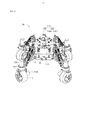
- FIG. 1 is a perspective view of a movable device according to an embodiment of the present invention.
- Figure 2 is a partial exploded view of the movable device of Figure 1.
- Figure 3 is another perspective view of the structure of Figure 2.
- FIG. 4 is a perspective view of a mobile photographing apparatus according to an embodiment of the present invention.
- FIG. 5 is a schematic illustration of a mobile device control system in accordance with an embodiment of the present invention.
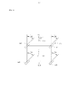
- FIG. 6 is a schematic diagram of a translational movement of a movable device according to an embodiment of the present invention.
- Fig. 7 is a schematic view showing the steering movement of the movable device according to the embodiment of the present invention.
- FIG. 8 is a flowchart of a method of controlling a mobile device according to an embodiment of the present invention.
- FIG. 9 is a sub-flow diagram of the mobile device control method of FIG.
- Mobile device 100 Chassis 10 Bottom 11 Top surface 12 side 13 Connection 14 Wheel assembly 20 Wheel body twenty one Drive mechanism twenty two First drive 221 First fixed part 2211 Connector 2211a Concave hole 2211b Line hole 2211c First positioning part 2211d Weight reduction hole 2211e First turning part 2212 Plane department 2212a Second drive 222 Second fixed part 2221 Second rotating part 2222 Support frame 223 Vertical support 2231 Lateral support 2232 Assembly department 2232a Center slot 2232b Outer slot 2232c Slip ring 224 Inner ring 2241 Second conductive portion 2241a Mounting holes 2241b Outer ring 2242 First conductive part 2242a First mating part 2242b Isolation 225 First contact 2251 Second contact 2252 Shock absorption component 30 support 31 First vertical frame 311 Extension frame 3111 Second vertical frame 312 First cross 313 Second cross frame 314 Buffer 32 Telescopic rod 321 Coil spring 322 Camera 200 Camera 201 Carrier 202 Shock absorber 202a Yuntai 202b Shock absorber ball 202c Mobile device control
- a component when referred to as being “fixed” to another component, it can be directly on the other component or the component can be present.
- a component When a component is considered to "connect” another component, it can be directly connected to another component or possibly a central component.
- a component When a component is considered to be “set to” another component, it can be placed directly on another component or possibly with a centered component.
- the terms “vertical,” “horizontal,” “left,” “right,” and the like, as used herein, are for illustrative purposes only.
- a movable device 100 includes a chassis 10 , a plurality of wheel assemblies 20 , and a plurality of shock absorbing assemblies 30 corresponding to the wheel assemblies 20 .
- Each of the wheel assemblies 20 is coupled to the chassis 10 by a corresponding shock absorbing assembly 30.
- the chassis 10 is the main load-bearing structure of the movable device 100, which is connected to the wheel assembly 20 and can carry various types of loads and/or functional modules, for example, a camera, a battery, a controller, and a wireless communication component. , circuit boards, power lines, etc.
- the chassis 10 is substantially square, and includes a bottom surface 11 , a top surface 12 , and a side surface 13 .
- the bottom surface 11 is substantially parallel to the top surface 12, and the side surface 13 connects the bottom surface 11 and the top surface 12 and is substantially perpendicular to the bottom surface 11 and the top surface 12.
- the chassis 10 has a hollow box shape, and its internal space can accommodate suitable loads and/or functional modules such as batteries, controllers, circuit boards, power lines, and the like.
- the chassis 10 includes a plurality of connecting portions 14 corresponding to the shock absorbing assembly 30, each of the connecting portions 14 for connecting a corresponding shock absorbing assembly 30.
- the number of the connecting portions 14 is four, and the four connecting portions 14 are respectively located at the four corners of the chassis 10.
- each of the connecting portions 14 is a recessed structure formed at a corner of the chassis 10, and the recessed structure can receive and fix a corresponding portion of the shock absorbing assembly 30.
- the bottom surface and/or the side surface of the inner portion of the connecting portion 14 may be provided with a connecting structure (not shown), and the connecting structure may be a connecting structure such as a connecting hole or a connecting post, and the connecting portion 14 is connected by the connecting structure.
- the shock absorbing assembly 30 is a recessed structure formed at a corner of the chassis 10, and the recessed structure can receive and fix a corresponding portion of the shock absorbing assembly 30.
- the bottom surface and/or the side surface of the inner portion of the connecting portion 14 may be provided with a connecting structure (not shown), and the connecting structure may be a connecting structure such as a connecting hole or a connecting post, and the connecting portion 14 is connected by the connecting structure.
- the shock absorbing assembly 30 is a recessed structure formed at a corner of the chassis 10, and the recessed structure can receive and fix a
- the shape of the chassis 10 is not limited to the above-described embodiments, and may be arbitrarily changed according to different needs, such as circular, elliptical, streamlined and other regular or irregular shapes.
- Each of the wheel assemblies 20 includes a wheel body 21 and a drive mechanism 22.
- the wheel body 21 is used to drive the movable device 100 forward, backward and/or steered.
- the drive mechanism 22 is used to drive the wheel body 21 to rotate and turn.
- the wheel body 21 is a rubber wheel. It can be understood that the wheel body 21 can also be a plastic wheel or any other suitable material.
- the center of the wheel body 21 is provided with a rim and a spoke (not labeled) for mounting a tire, and the spoke can make the rim force more uniform and less likely to be deformed.
- the wheel body 21 can be any other suitable structure, and is not limited to the above.
- the wheel body 21 can be an integral solid rubber wheel, a plastic wheel or the like.
- the driving mechanism 22 includes a first driving member 221, a second driving member 222, and a support frame 223.
- the wheel body 21 is rotatably connected to the support frame 223, and the first driving member 221 and the second driving member 222 are disposed on the support frame 223.
- the first driving member 221 and the second driving member 222 are rotating electrical machines. More specifically, the first driving member 221 and the second driving member 222 may be brushless motors and brushes. Motor or other type of motor.
- the rotation axis of the first driving member 221 is substantially perpendicular to the central axis of the wheel body 21, and the rotation axis of the second driving member 222 passes through the central axis of the wheel body 21, in other words, the first driving member
- the axis of rotation of 221 is substantially perpendicular to the axis of rotation of the second drive member 222.
- the first driving component 221 includes a first fixing portion 2211 and a first rotating portion 2212 that is rotatable relative to the first fixing portion 2211 .
- the first fixing portion 2211 can be A part of the stator of the first driving member 221 or fixedly connected to the stator, the first rotating portion 2212 is a part of the rotor of the first driving member 221 or a component fixedly connected to the rotor.
- a connecting member 2211a for connecting the corresponding shock absorbing assembly 30 is formed on the first fixing portion 2211, and a part of the structure of the shock absorbing assembly 30 is fixedly connected to the connecting member 2211a.
- the connecting member 2211a is an annular flange formed on the circumferential side of the first fixing portion 2211, and the connecting member 2211a is located at a lower end of the first fixing portion 2211.
- the connecting member 2211a can be a block protrusion, a column protrusion or an arc protrusion.
- the connecting member 2211a may also be a holding structure capable of engaging a portion of the shock absorbing assembly 30; the connecting member 2211a may be formed at a top end, a middle portion, or the like of the first fixing portion 2211.
- the connecting member 2211a may also be omitted.
- the first fixing portion 2211 is directly fixedly connected to a partial structure of the shock absorbing assembly 30.
- the connecting member 2211a is provided with a recessed hole 2211b on a side surface of the corresponding wheel body 21.
- the recessed hole 2211b is a circular hole, and the central axis rotates with the first rotation. The axes coincide.
- the recess 2211b makes the connecting member 2211a annular toward one end of the corresponding wheel body 21.
- a wire hole 2211c and a first positioning portion 2211d are provided on the bottom surface of the recessed hole 2211b, and the wire hole 2211c is provided for the wire to pass through.
- the shape of the recessed hole 2211b is not limited to that described in the above embodiment, and may be any suitable change as well as the actual shape.
- the connecting member 2211a is provided with a weight reducing hole 2211e facing the end surface of the corresponding wheel body 21.
- the weight reducing hole 2211e can reduce the overall weight of the first driving member 221, thereby reducing the
- the overall weight of the movable device 100 is such that the movable device 100 has greater carrying capacity under the same driving force.
- the lightening hole 2211e includes a plurality of holes arranged in a substantially annular shape. It can be understood that the weight reducing hole 2211 can also be disposed at other positions of the connecting member 2211a, and/or disposed on the first fixing portion 2211 except for other positions of the connecting member 2211a.
- the first rotating portion 2212 is partially located in the first fixing portion 2211 and partially protrudes from the first fixing portion 2211.
- the portion of the first rotating portion 2212 extending from the outside of the first fixing portion 2211 is substantially columnar.
- the portion of the first rotating portion 2212 that protrudes outside the first fixing portion 2211 is a cylinder.
- the end side portion of the first fixing portion 2211 from which the first rotating portion 2212 protrudes has a flat portion 2212a that makes the end of the first fixing portion 2211 a non-circular cross section .
- the end of the first rotating portion 2212 extending from the first fixing portion 2211 is inserted into the support frame 223, and the planar portion 2212a can prevent the first rotating portion 2212 from being between the supporting frame 223 Relative rotation.
- the second driving member 222 has a similar structure to the first driving member 221, except that the rotation axis of the second driving member 222 is substantially perpendicular to the rotation axis of the first driving member 221 .
- the second driving member 222 includes a second fixing portion 2221 and a second rotating portion 2222 that is rotatable relative to the second fixing portion 2221.
- the second fixing portion 2221 can be fixedly connected to the support frame, and the end of the second rotating portion 2222 extending from the second fixing portion 2221 is connected to the wheel body 21, and the second rotating portion 2222 is
- the wheel body 21 can be axially rotated when rotated, so that the second driving member 222 can drive the wheel body 21 to advance or retreat.
- the support frame 223 is configured to support the first driving member 221, the second driving member 222, and the wheel body 21.
- the support frame 223 has a substantially " ⁇ " shape, and includes two spaced apart vertical support members 2231 and a lateral support member 2232 connected to the vertical support member 2231.
- the vertical support member 2231 are respectively connected to the opposite sides of the two phases of the lateral support 2232.
- the vertical support member 2231 and the lateral support member 2232 are both in a plate shape.
- the wheel body 21 is rotatably clamped between the two vertical support members 2231, and the second fixing portion 2221 of the second driving member 222 is fixedly coupled to one of the vertical support members 2231
- One side of the wheel body 21 is connected to the second driving member 222 such that the wheel body 21 that the second driving member 222 can drive rotates, and the other side of the wheel body 21 is another
- the vertical supports 2231 are rotatably connected.
- a middle portion of the lateral support member 2232 is provided with a fitting portion 2232a that is coupled to the first driving member 221.
- the mounting portion 2232a has a substantially disk shape, and the mounting portion faces a side surface of the first driving member 221 with a central groove 2232b and an annular outer groove 2232c surrounding the central groove 2232b.
- the outer groove 2232c is substantially annular.
- the center groove 2232b is disposed coaxially with the outer groove 2232c and spaced apart from each other.
- An insertion hole (not shown) connectable to the first rotating portion 2212 is formed on a bottom surface of the central slot 2232b, and the shape of the insertion hole and the first rotating portion 2212 protrudes from the first The shape of the end of the fixing portion 2211 is adapted.
- the first rotating portion 2212 and the supporting frame 223 cannot rotate relative to each other. At this time, the rotation of the first rotating portion 2212 can drive the support frame 223 to rotate at the same time.
- the driving mechanism 22 further includes a slip ring 224 and a spacer 225 disposed between the first driving member 221 and the support frame 223.
- the slip ring 224 includes an inner ring 2241 and an outer ring 2242 rotatably coupled to the inner ring 2241, the inner ring 2241 being simultaneously in electrical contact with the outer ring 2242 when the inner ring 2241 is opposite to the inner ring 2241 When the outer ring 2242 is rotated, the inner ring 2241 and the outer ring 2242 are always in electrical contact.
- a first conductive portion 2242a is formed on an outer surface of the outer ring 2242
- a second conductive portion 2241a is formed on an outer surface of the inner ring 2241
- the first conductive portion 2242a and the second conductive portion 2241a pass through
- the outer ring 2242 can be electrically connected to each other by electrical contact with the inner ring 2241.
- the first conductive portion 2242a is protruded from a side surface of the outer ring 2242 facing the first driving member 221
- the second conductive portion 2241a is protruded from the inner ring 2241.
- the first conductive portion 2242a and the second conductive portion 2241a are both in a convex column shape. It can be understood that the first conductive portion 2242a and the second conductive portion 2241a may also be other structures capable of connecting wires such as a wire slot; the first conductive portion 2241a and the second conductive portion 2241a may also be directly For the wire. The number of the first conductive portion 2242a and the second conductive portion 2241a is two.
- a first engaging portion 2242b corresponding to the first positioning portion 2211d is disposed on a side surface of the outer ring 2242 facing the first driving member 221, and the first positioning portion 2211d and the first matching portion are The 2242b cooperates to form a non-rotation connection between the outer ring 2242 and the first fixing portion 2211.
- the first positioning portion 2211d is formed on the first fixing portion 2211
- the first engaging portion 2242b is a hole formed in the outer ring 2242.
- first positioning portion 2211d and the first engaging portion 2242b may be interchanged, that is, the first engaging portion 2242b is a protrusion formed on the outer ring 2242, the first A positioning portion 2211d is a hole that is opened in the first fixing portion 2211.
- a mounting hole 2241b is defined in a side surface of the inner ring 2241 toward the support frame 223, and the mounting hole 2241 is configured to connect the inner ring 2241 to the support frame 223.
- the spacer 225 can reduce the rotational resistance between the first fixing portion 2211 of the first driving member 221 and the support frame 223, so that the rotation is smoother and smoother.
- the spacer 225 is a planar needle bearing, and includes a first contact portion 2251, a second contact portion 2252, and a roll disposed between the first contact portion 2251 and the second contact portion 2252.
- a needle (not shown) that enables relative movement between the first contact portion 2251 and the second contact portion 2252.
- the first contact portion 2251 and the second contact portion 2252 are each substantially annular and flat.
- the spacer 225 may also be a pair of lubricating sheets disposed opposite to each other, and the two lubricating sheets can slide relative to each other.
- the lower portion of the slip ring 224 is received in the central slot 2232b, and the second conductive portion 2241a is connectable to a wire disposed on the support frame 223 and electrically connected to the second driving member 222 (
- the inner ring 2241 is fixed to the support frame 223 by a fastener (such as a bolt, a screw, etc., not shown) engaging with the mounting hole 2241b; the spacer 225 is received in In the outer groove 2232c, the first contact portion 2251 is in contact with the outer groove 2232c; the first driving member 221 is connected to the support frame 223, and the connecting member 2211a faces the corresponding wheel body.
- the wires may pass through the wire hole 2211c and pass through the corresponding shock absorbing assembly 3 0 extending to the chassis 10, the wires being connected to a power supply and/or a controller of the chassis 10, the wires being electrically connected to the first driver 221 or the power source and/or controller through another
- the first driving portion 2211d is inserted into the corresponding first engaging portion 2242b to restrict the between the outer ring 2242 and the first fixing portion 2211. Relative rotation.
- the first driving member 221 can control the steering of the wheel body 21 to change the moving direction of the movable device 100; the second driving member 222 can control the rotation of the wheel body 21 about its central axis. In order to move the movable device 100, the second driving member 222 can drive the wheel body 21 to advance or retreat.
- the use of the slip ring 224 can avoid the limitation of the rotation by the wire connection, so that the wheel body 21 that the first driving member 221 can drive can be steered at any angle, and thus is more suitable for work in a narrow space.
- the inner ring 2241 can be fixedly connected to the first fixing portion 2211, and the outer ring 2242 can be fixedly connected to the support frame 223.
- the shock absorbing assembly 30 is used to buffer the impact of the vibration of the wheel assembly 20 on the chassis 10 to protect the load and/or function modules carried by the chassis 10 from being affected or less susceptible to vibration.
- Each of the shock absorbing assemblies 30 includes a deformable bracket 31 and a cushioning member 32 disposed on the bracket 31.
- the deformable bracket 31 includes a first vertical frame 311, a second vertical frame 312, a first cross frame 313, and a second cross frame 314. Two ends of the first vertical frame 311 are respectively pivotally connected to the first horizontal frame 313 and the second horizontal frame 314, and two ends of the second vertical frame 312 are respectively connected to the first horizontal frame 313 and The second cross frame 314 is pivotally connected.
- first vertical frame 311, the second vertical frame 312, the first horizontal frame 313, and the second horizontal frame 314 are connected end to end to form a substantially parallelogram frame shape, and the first The length of the cross frame 313 is substantially the same as the length of the second cross frame 314.
- the second horizontal frame 314 is located below the first horizontal frame 313.
- the first vertical frame 311 is fixedly connected to the chassis 10, and specifically, each of the first vertical frames 311 is fixedly connected to the connecting portion 14 of the chassis 10, and the first vertical frame 311 can be bolted.
- the fasteners are fixed to the chassis 10 and may be integrally formed with the chassis 10.
- An extension frame 3111 is formed at the top of each of the first vertical frames 311, and the extension frame 3111 is protruded such that the length of the first vertical frame 311 is larger than the second vertical frame 312.
- the second vertical frame 312 is fixedly connected to the first fixing portion 2211.
- the cushioning member 32 is capable of damping deformation of the bracket 31, thereby mitigating shocks received by the wheel assembly 20.
- the cushioning member 32 may include a damper member, an elastic member, and the like. Damping members such as liquid dampers, air pressure dampers, and reluctance dampers. Elastic members such as tension springs, compression springs, elastic rubber members, and the like.
- each of the buffering members 32 includes a telescopic rod 321 and a coil spring 322 sleeved on the telescopic rod 321 .
- the two ends of the coil spring 322 respectively abut against the two ends of the telescopic rod 321 .
- the telescopic rods 321 are wrapped in a plurality of sections, and the plurality of sections of the telescopic rods are relatively slidable to change the overall length of the telescopic rods 321 .
- the number of the buffer members 32 can be any suitable change according to actual needs.
- the number of the buffer members 32 may be One, three, four, five or more.
- bracket 31 is a parallelogram frame
- the parallelism of the first vertical frame 311 and the second vertical frame 312 can be always maintained, as long as the first vertical frame 311 is vertically connected to the chassis, It is ensured that the second vertical frame 312 is always vertical, so that the wheel assembly 20 is not affected by the additional torque, so that the wheel assembly 20 can be prevented from being damaged by the additional torque, and the wheel assembly can be guaranteed. 20 control accuracy and ease of control.
- the bracket 31 is not limited to the above-illustrated embodiment, and may be any other suitable mechanism.
- the bracket 31 may include only one cross frame, and the two ends of the cross frame respectively The chassis 10 and the first fixing portion 2211 are pivotally connected.
- the two ends of the buffering member 32 are respectively connected to the chassis 10 and the first fixing portion 2211, and are inclined with respect to the horizontal frame.
- the predetermined angle; the bracket 21 may also be a substantially pentagonal, hexagonal, or other polygonal deformable frame.
- the bracket 31 may be omitted, and the cushioning member 32 may be disposed only between the first fixing portion 2211 and the chassis 10.
- the movable device 100 can use the slip ring 224 to break the limit of the steering angle of the wheel assembly 20, thereby making the movable device 100 more flexible, realizing the omnidirectional movement of the movable device 100, and improving the
- the movable device 100 is adapted to work in a small space.
- the mobile device 100 can carry a specific load on a suitable load.
- the mobile device 100 is equipped with a photographing device 200.
- the movable device 100 and the photographing device 200 together constitute a mobile photographing device, and the mobile photographing device can perform moving photographs and/or Or the function of the video.
- the photographing device 200 further includes a photographing device 201 and a carrier 202 for carrying the photographing device 201.
- the imaging device 201 can be an electronic product having a video recording function such as a camera, a video camera, a mobile phone, or a tablet computer. In the embodiment, the imaging device 201 is a video camera.
- the carrier 202 is used to support the camera device 200 on the chassis 10.
- the carrier 202 includes a shock absorbing seat 202a and a cloud platform 202b.
- the damper 202a and the pan/tilt 202b also constitute a stabilizing component capable of increasing the imaging stability of the imaging device 200.
- the shock absorbing seat 202a is fixedly disposed on the chassis 10, and the shock absorbing seat 202a is provided with a shock absorbing ball 202c.
- the shock absorbing ball 202c is a rubber shock absorbing ball, and the shock absorbing ball 202c is disposed at the Between the shock absorbing seat 202a and the pan/tilt head 202b, it is possible to effectively reduce or eliminate the influence of low frequency vibration on the photographing device 200.
- the pan/tilt head 202b can compensate for the target/direction offset caused by the vibration of the photographing device 200 in the rotation direction, and/or the pan/tilt head 202b can adjust the posture, direction, and the like of the photographing device 200 according to the control command.
- Shooting parameters In the embodiment, the pan/tilt head 202b is a three-axis pan/tilt, and the pan/tilt head 202b is capable of adjusting the photographing device 200 around a heading (Yaw) axis, a roll axis, and a pitch axis. In other embodiments, the pan/tilt head 202b may also be a two-axis pan/tilt head or a single-axis pan/tilt head.
- the number of the wheel assemblies 20 and the corresponding number of the shock absorbing members 30 are four. It can be understood that the number of the wheel assemblies 20 and the corresponding number of the shock absorbing assemblies 30 can be any suitable change according to the actual situation, and is not limited to the description of the above embodiments, such as the number of the wheel assemblies 20 and The number of the shock absorbing members 30 corresponding thereto may be three, five, six, seven, eight, ten or more.
- the movement of the movable device 100 can be controlled by a remote controller or can be controlled autonomously.
- An exemplary control system and control method of the movable device 100 will be specifically described below with reference to the accompanying drawings.
- the movable device control system 300 includes a remote controller 40, a receiving unit 50, a controller 60, a plurality of the wheel bodies 21, a plurality of the first driving members 221, and a plurality of the second driving members 222, and more.
- the receiving unit 50, the controller 60, the wheel body 21, the first driving member 221, the second driving member 222, the first driving control unit 70, and the second driving control unit 80 is disposed on the movable device 100.
- the remote controller 40 is separately provided from the movable device 100, and the remote controller 40 is communicatively coupled to the receiving unit 50.
- the remote controller 40 can be connected to the receiving unit 50 in a wired or wireless manner.
- the remote controller 40 and the receiving unit 50 are communicably connected in a wireless manner.
- the remote controller 40 is used to control the movement and/or steering of the movable device 100.
- the remote controller 40 is capable of generating a remote control signal.
- the remote controller 40 is a rocker type remote controller, and the remote control signal is a rocker signal generated by the joystick.
- the remote controller 40 includes a first rocker 41 and a second rocker 42. The first rocker 41 and the second rocker 42 can generate a corresponding rocker signal when rocking, and the remote controller 40 will The rocker signal is sent to the receiving unit 50.
- the first rocker 41 is used to control a turning motion of the movable device 100, such as the steering of the movable device 100 and a turning radius.
- the left and right direction of the first rocker 41 respectively generate a rocker signal for turning the left and right directions of the movable device 100, and the amplitude of the left and right toggles of the first rocker 41
- the toggle amplitude of the first rocker 41 has a preset proportional relationship with the turning radius of the movable device 100, that is, each of the first rockers 41
- the toggle amplitude corresponds to a turning radius of the movable device 100.
- the toggle amplitude of the first rocker 41 is inversely proportional to the turning radius of the movable device 100, that is, The greater the dialing amplitude of the first rocker 41, the smaller the turning radius of the movable device 100, that is, the greater the dialing amplitude of the first rocker 41, the turning of the movable device 100 The more urgent the movement.
- the second rocker 42 is used to control the translational movement of the movable device 100, such as the translational direction and translational speed of the movable device 100.
- the toggle direction of the second rocker 42 corresponds to the moving direction of the movable device 100
- the toggle amplitude of the second rocker 42 corresponds to the moving speed of the movable device 100.
- the upper and lower toggles of the second rocker 42 respectively correspond to the forward and backward movement of the movable device 100
- the left and right toggles of the second rocker 42 respectively correspond to the
- the shifting direction of the second rocker 42 is not limited to the above, for example, the dialing direction of the second rocker 42 may be the same as the above, The downward, left, and right directions are at a certain angle.
- the direction in which the second rocker 42 is toggled may also correspond to a specific translation direction of the movable device 100.
- the dialing amplitude of the second rocker 42 is in a predetermined proportional relationship with the translation speed of the movable device 100, that is, each of the toggle amplitudes of each of the second rockers 42 corresponds to the movable a shifting speed of the device 100, in the present embodiment, the dialing amplitude of the second rocker 42 is proportional to the translation speed of the movable device 100, in other words, the dialing amplitude of the second rocker 42 The larger the translation speed of the movable device 100 is, the larger.
- first rocker 41 and the second rocker 42 are physical rockers. It can be understood that the first rocker 41 and the second rocker 42 may also be virtual rockers. That is, the first rocker 41 and the second rocker 42 may be a rocker icon displayed on a touch screen, and by dragging the rocker icon, the control effect of the physical rocker can be simulated.
- the remote controller 40 can be a portable touch electronic device, such as a mobile phone, a tablet computer, a notebook computer, or the like.
- the receiving unit 50 is configured to receive the remote control signal sent by the remote controller 40 and transmit the remote control signal to the controller 60.
- the receiving unit 50 and the remote controller 40 can communicate with each other through a communication manner such as WiFi, Bluetooth, 2G, 3G, 4G, and 5G.
- the controller 60 analyzes the motion mode of the movable device 100 corresponding to the remote control signal according to the remote control signal, and controls the movable device 100 to move in the motion mode.
- the controller 60 analyzes the source of the remote control signal from the received remote control signal. For example, the controller 60 can recognize a rocker signal from the first rocker 41 and a rocker signal of the second rocker 42 from the remote control signal. The controller 60 controls the movable device 100 to perform a turning motion according to the rocker signal of the first rocker 41, and controls the movable device 100 to perform a translational motion according to the rocker signal of the second rocker 42. .
- the controller 60 separately calculates the required speed and/or steering angle of each of the wheel bodies 21 of the movable device 100 according to the remote control signal, and respectively respectively controls signals.
- the first drive control unit 70 and the second drive control unit 80 corresponding to each of the wheel bodies 21 are sent to control the wheel body 21 to move at a corresponding speed and/or steering angle.
- the first drive control unit 70 and the second drive control unit 80 are electronic governors.
- FIGS. 6 and 7 A specific embodiment of calculating the speed and/or steering angle required for each of the wheel bodies 21 in accordance with the remote control signal will be exemplified below with reference to FIGS. 6 and 7.
- 6 is a schematic diagram of a translational movement of the movable device 100
- FIG. 7 is a schematic diagram of a translational motion and a turning motion of the movable device 100.
- a Cartesian coordinate system is established with the center C of the movable device 100 as a coordinate origin, wherein the moving device 100 has a forward direction of a Y-axis positive direction, a backward direction of a Y-axis negative direction, and a rightward translation.
- the direction is the positive X-axis direction
- the left-direction translation direction is the X-axis negative direction.
- the wheel body 21 is respectively labeled as a right front wheel w1, a left front wheel w2, a left rear wheel w3, and a right rear wheel w4, and the controller 60 can obtain the The forward and backward translation speed of the mobile device 100 is given And left and right translation speed given .
- the actual moving speed of the movable device 100 is When moving, the angle between the actual moving direction of the movable device 100 and the Y axis is .
- each wheel body 21 In the case of translational motion, the speed and direction of movement of each wheel body 21 are the same, ie , .
- the controller 60 can obtain a turning radius of the movable device 100 according to the remote control signal. ,among them The distance from the center C of the movable device 100 to the turning center O.
- the steering angle and speed required for each wheel body 21 during the turning motion are not completely the same. For example, there is a speed difference between the wheel bodies 21 on the left and right sides, and in order to ensure a smooth turning, the moving direction and turn of each wheel body 21 are required.
- the center of the circle O remains vertical.
- d 1 is the distance between the center of the right front wheel w1 and the turning center O, and r is the distance from the center to the side of the movable device 100.
- the steering angle of the left front wheel w2 is:
- d 2 is the distance between the center of the left front wheel w2 and the turning center O.
- the steering angle of the left rear wheel w3 is:
- the steering angle of the right rear wheel w4 is:
- d 3 is the distance between the center of the left rear wheel w3 and the turning center O
- d 4 is the distance between the center of the right rear wheel w4 and the turning center O.
- the controller 60 is configured according to the steering angle given and speed, and respectively sends a control signal to the first driving control unit 70 and the second driving control unit 80 corresponding to each of the wheel bodies 21 to The wheel body 21 is controlled to move at a corresponding speed and/or steering angle.
- the first driving control unit 70 is configured to control the corresponding first driving member 221 to drive the corresponding wheel body 21 with a corresponding steering angle according to a control signal of the controller 60;
- the second driving The drive control unit 80 can convert the speed of each of the wheel bodies 21 to the corresponding rotational speed of the second drive member 222, and the second drive control unit 80 is configured to control signals according to the controller 60.
- the corresponding second driving member 222 controls the corresponding wheel body 21 to rotate in the axial direction corresponding to the rotational speed.
- the first driving control unit 70 can control the steering and the rotating speed of the first driving member 221 according to the control signal, and the second driving control unit 80 can control the second driving member 222 according to the control signal. Steering and speed. It can be understood that the first driving control unit 70 and the second driving control unit 80 may be independently disposed, or may be integrated into an integrated arrangement, and the first driving control unit 70 corresponding to the plurality of wheel bodies 21 The plurality of wheel bodies 21 may be integrated into one body corresponding to the second drive control unit 80.
- the controller 60 can be accompanied by the functions of the first driving control unit 70 and the second driving control unit 80. At this time, the first driving control unit 70 and the The second drive control unit 80 can be omitted.
- the first driving member 221 is configured to rotate according to a corresponding control signal of the first driving control unit 70 to drive the corresponding wheel body 21 to turn, thereby turning the movable device 100 at a predetermined angle;
- the second driving member 222 is configured to rotate according to a corresponding control signal of the second driving control unit 80 to drive the corresponding wheel body 21 to rotate, thereby moving the movable device 100 at a predetermined speed.
- the movable device control system 300 can perform independent steering and/or translational driving for each of the wheel bodies 21, so that the movement and/or steering of the movable device 100 is more flexible and adapts to work in a small space.
- the movable device control system 300 controls the translation and steering of the movable device 100 by the rocker signals generated by different rockers, respectively, and the same remote controller 40 can be more easily controlled to perform complex motions of the movable device 100. .
- the movable device control method is suitable for controlling the aforementioned removable device 100 and can be implemented by the movable device control system 300, and includes the following steps:
- the step may be performed by the remote controller 40, and the remote control signal may include a rocker signal generated by the first rocker 41 and/or a rocker signal generated by the second rocker 42, the first rocker
- the rocker signal of 41 is used to control the turning motion of the movable device 100, such as the steering of the movable device 100 and the turning radius.
- the left and right direction of the first rocker 41 respectively generate a rocker signal for turning the left and right directions of the movable device 100, and the amplitude of the left and right toggles of the first rocker 41
- the toggle amplitude of the first rocker 41 has a preset proportional relationship with the turning radius of the movable device 100, that is, each of the first rockers 41
- the toggle amplitude corresponds to a turning radius of the movable device 100.
- the toggle amplitude of the first rocker 41 is inversely proportional to the turning radius of the movable device 100, that is, The greater the dialing amplitude of the first rocker 41, the smaller the turning radius of the movable device 100, that is, the greater the dialing amplitude of the first rocker 41, the turning of the movable device 100 The more urgent the movement.
- the rocker signal of the second rocker 42 is used to control the translational movement of the movable device 100, such as the translational direction and translational speed of the movable device 100.
- the toggle direction of the second rocker 42 corresponds to the moving direction of the movable device 100
- the toggle amplitude of the second rocker 42 corresponds to the moving speed of the movable device 100.
- the upper and lower toggles of the second rocker 42 respectively correspond to the forward and backward movement of the movable device 100
- the left and right toggles of the second rocker 42 respectively correspond to the
- the shifting direction of the second rocker 42 is not limited to the above, for example, the dialing direction of the second rocker 42 may be the same as the above, The downward, left, and right directions are at a certain angle.
- the direction in which the second rocker 42 is toggled may also correspond to a specific translation direction of the movable device 100.
- the dialing amplitude of the second rocker 42 is in a predetermined proportional relationship with the translation speed of the movable device 100, that is, each of the toggle amplitudes of each of the second rockers 42 corresponds to the movable a shifting speed of the device 100, in the present embodiment, the dialing amplitude of the second rocker 42 is proportional to the translation speed of the movable device 100, in other words, the dialing amplitude of the second rocker 42 The larger the translation speed of the movable device 100 is, the larger.
- the remote control signal may be a signal generated by a physical rocker or a signal generated by a virtual rocker.
- the receiving unit 50 is capable of receiving the remote control signal transmitted by the remote controller 40 and transmitting the remote control signal to the controller 60.
- the receiving unit 50 and the remote controller 40 can communicate with each other through a communication manner such as WiFi, Bluetooth, 2G, 3G, 4G, and 5G.
- step S803 may further include the following steps:
- step S803b controlling the movable device 100 to make a turning motion according to the rocker signal of the first rocker 41, and controlling the movable device 100 to perform a translational motion according to the rocker signal of the second rocker 42. More specific steps of this step may include separately calculating, according to the rocker signal, a speed and/or a steering angle required by each of the wheel bodies 21 of the movable device 100 in a corresponding motion mode; controlling each of the The wheel bodies 21 are respectively moved in accordance with the respective speeds and/or steering angles.
- step 803 is implemented by the controller 60, the first driving control unit 70, the second driving control unit 80, the first driving member 221, and the second driving member 222.
- the movable device control method can realize independent steering and/or translational driving of each of the wheel bodies 21, so that the movement and/or steering of the movable device 100 is more flexible and adapts to work in a narrow space.
- the movable device control system 300 controls the translation and steering of the movable device 100 by the rocker signals generated by different rockers, respectively, and the same remote controller 40 can be more easily controlled to perform complex motions of the movable device 100. .
Landscapes
- Engineering & Computer Science (AREA)
- General Engineering & Computer Science (AREA)
- Mechanical Engineering (AREA)
- Physics & Mathematics (AREA)
- Aviation & Aerospace Engineering (AREA)
- General Physics & Mathematics (AREA)
- Remote Sensing (AREA)
- Multimedia (AREA)
- Signal Processing (AREA)
- Computer Vision & Pattern Recognition (AREA)
- Radar, Positioning & Navigation (AREA)
- Automation & Control Theory (AREA)
- Electromagnetism (AREA)
- Vehicle Body Suspensions (AREA)
- Toys (AREA)
- Manipulator (AREA)
- Studio Devices (AREA)
- Accessories Of Cameras (AREA)
Abstract
一种可移动装置(100),包括底盘(10)以及与底盘(10)连接的多个车轮组件(20),每一个车轮组件(20)包括轮体(21)以及驱动机构(22),驱动机构(22)包括第一驱动件(221)以及第二驱动件(222),第一驱动件(221)用于驱动轮体(21)转向以改变可移动装置(100)的移动方向,第二驱动件(222)用于驱动轮体(21)轴向转动以带动可移动装置(100)移动,每一个轮体(21)分别由对应的第一驱动件(221)以及第二驱动件(222)独立驱动进行转向及轴向转动。还涉及一种具有上述可移动装置(100)的移动拍摄设备、可移动装置控制系统(300)及方法。
Description
本发明涉及移动机构,尤其涉及一种可移动装置,具有所述可移动装置的移动拍摄设备,所述可移动装置的控制系统及方法。
如今,可移动装置,例如可移动拍摄车、可移动服务机器人等,已被越来越广泛地应用于很多领域,例如,影视拍摄、服务、搜救、探险、竞技游戏等。所述可移动装置单独或者搭载预定功能的负载以执行特定的任务。
但是,现有的可移动装置的移动和转向不够灵活,不能够适应狭小空间的作业环境。
有鉴于此,有必要提供一种避免上述问题的可移动装置、移动拍摄设备、可移动装置控制系统及方法。
一种可移动装置,包括底盘以及与所述底盘连接的多个车轮组件。每一个所述车轮组件包括轮体以及驱动机构。所述驱动机构包括第一驱动件以及第二驱动件。所述第一驱动件用于驱动所述轮体转向以改变所述可移动装置的移动方向。所述第二驱动件用于驱动所述轮体轴向转动以带动所述可移动装置移动。每一个所述轮体分别由对应的所述第一驱动件以及第二驱动件独立驱动进行转向及轴向转动。
一种移动拍摄设备,包括可移动装置以及搭载于所述可移动装置上、用于安装拍摄装置的承载件。所述可移动装置包括底盘以及与所述底盘连接的多个车轮组件。每一个所述车轮组件包括轮体以及驱动机构。所述驱动机构包括第一驱动件以及第二驱动件。所述第一驱动件用于驱动所述轮体转向以改变所述可移动装置的移动方向。所述第二驱动件用于驱动所述轮体轴向转动以带动所述可移动装置移动。每一个所述轮体分别由对应的所述第一驱动件以及第二驱动件独立驱动进行转向及轴向转动。
一种可移动装置控制系统,用于控制可移动装置的运动。所述可移动装置具有多个车轮组件。每一个所述车轮组件包括轮体以及驱动机构,每一个所述车轮组件包括轮体以及驱动机构。所述驱动机构包括用于驱动所述轮体转动以带动所述可移动装置移动的第一驱动件,以及用于驱动所述轮体转向以使所述可移动装置改变移动方向的第二驱动件。所述可移动装置控制系统包括:
接收单元,用于接收遥控信号;以及
控制单元,与所述接收单元通信连接,用于依据所述遥控信号获得每一个所述轮体所需的转向角度及速度,并控制所述第一驱动件以及第二驱动件分别独立驱动对应的所述轮体以对应的所述转向角度及速度运动,进而分别控制所述可以动装置的移动方向及移动速度。
一种可移动装置控制方法,用于控制可移动装置的运动。所述可移动装置具有多个车轮组件。每一个所述车轮组件包括轮体以及驱动机构。每一个所述车轮组件包括轮体以及驱动机构。所述驱动机构包括用于驱动所述轮体转动以带动所述可移动装置移动的第一驱动件,以及用于驱动所述轮体转向以使所述可移动装置改变移动方向的第二驱动件。所述可移动装置控制方法包括步骤:
接收遥控信号;
依据所述遥控信号获得每一个所述轮体所需的转向角度速度,并控制所述第一驱动件以及第二驱动件分别独立驱动对应的所述轮体以对应的所述转向角度及速度运动,进而分别控制所述可以动装置的移动方向及移动速度。
相对于现有技术,所述可移动装置、所述移动拍摄设备、所述可移动装置控制系统及方法实现了对每一个轮体转动和转向的独立驱动,能够使得所述可移动装置的移动、转向更为灵活,增加了对狭小作业环境的适应度。
图1是本发明实施方式的可移动装置的立体图。
图2是图1可移动装置的部分结构分解图。
图3是图2的结构的另一角度视图。
图4是本发明实施方式的移动拍摄设备的立体图。
图5是本发明实施方式的可移动装置控制系统的示意图。
图6是本发明实施方式的可移动装置的平移运动示意图。
图7是本发明实施方式的可移动装置的转向运动示意图。
图8是本发明实施方式的可移动装置控制方法的流程图。
图9是图8的可移动装置控制方法的子流程图。
| 可移动装置 | 100 |
| 底盘 | 10 |
| 底面 | 11 |
| 顶面 | 12 |
| 侧面 | 13 |
| 连接部 | 14 |
| 车轮组件 | 20 |
| 轮体 | 21 |
| 驱动机构 | 22 |
| 第一驱动件 | 221 |
| 第一固定部 | 2211 |
| 连接件 | 2211a |
| 凹孔 | 2211b |
| 线孔 | 2211c |
| 第一定位部 | 2211d |
| 减重孔 | 2211e |
| 第一转动部 | 2212 |
| 平面部 | 2212a |
| 第二驱动件 | 222 |
| 第二固定部 | 2221 |
| 第二转动部 | 2222 |
| 支撑架 | 223 |
| 竖向支撑件 | 2231 |
| 横向支撑件 | 2232 |
| 装配部 | 2232a |
| 中心槽 | 2232b |
| 外槽 | 2232c |
| 滑环 | 224 |
| 内环 | 2241 |
| 第二导电部 | 2241a |
| 安装孔 | 2241b |
| 外环 | 2242 |
| 第一导电部 | 2242a |
| 第一配合部 | 2242b |
| 隔离件 | 225 |
| 第一接触部 | 2251 |
| 第二接触部 | 2252 |
| 减震组件 | 30 |
| 支架 | 31 |
| 第一竖架 | 311 |
| 延伸架 | 3111 |
| 第二竖架 | 312 |
| 第一横架 | 313 |
| 第二横架 | 314 |
| 缓冲件 | 32 |
| 伸缩杆 | 321 |
| 螺旋弹簧 | 322 |
| 拍摄装置 | 200 |
| 拍摄装置 | 201 |
| 承载件 | 202 |
| 减震座 | 202a |
| 云台 | 202b |
| 减震球 | 202c |
| 可移动装置控制系统 | 300 |
| 遥控器 | 40 |
| 第一摇杆 | 41 |
| 第二摇杆 | 42 |
| 接收单元 | 50 |
| 控制器 | 60 |
| 第一驱动控制单元 | 70 |
| 第二驱动控制单元 | 80 |
| 右前轮 | w1 |
| 左前轮 | w2 |
| 左后轮 | w3 |
| 右后轮 | w4 |
如下具体实施方式将结合上述附图进一步说明本发明。
下面将结合本发明实施例中的附图,对本发明实施例中的技术方案进行清楚、完整地描述,显然,所描述的实施例仅仅是本发明一部分实施例,而不是全部的实施例。基于本发明中的实施例,本领域普通技术人员在没有做出创造性劳动前提下所获得的所有其他实施例,都属于本发明保护的范围。
需要说明的是,当组件被称为“固定于”另一个组件,它可以直接在另一个组件上或者也可以存在居中的组件。当一个组件被认为是“连接”另一个组件,它可以是直接连接到另一个组件或者可能同时存在居中组件。当一个组件被认为是“设置于”另一个组件,它可以是直接设置在另一个组件上或者可能同时存在居中组件。本文所使用的术语“垂直的”、“水平的”、“左”、“右”以及类似的表述只是为了说明的目的。
除非另有定义,本文所使用的所有的技术和科学术语与属于本发明的技术领域的技术人员通常理解的含义相同。本文中在本发明的说明书中所使用的术语只是为了描述具体的实施例的目的,不是旨在于限制本发明。本文所使用的术语“或/及”包括一个或多个相关的所列项目的任意的和所有的组合。在不冲突的情况下,下述的实施例及实施例中的特征可以相互组合。
请参阅图1,本发明一示例性的实施方式的可移动装置100包括底盘10、多个车轮组件20以及多个对应于所述车轮组件20的减震组件30。每一个所述车轮组件20通过对应的所述减震组件30连接于所述底盘10上。
所述底盘10为所述可移动装置100的主要承载结构,其连接所述车轮组件20并能够承载各种类型的负载及/或功能模块,例如,拍摄装置、电池、控制器、无线通信元件、电路板、电力线路等。
本实施方式中,所述底盘10大致呈方形,其包括底面11、顶面12以及侧面13。所述底面11大致平行于所述顶面12,所述侧面13连接所述底面11及顶面12并大致垂直于所述底面11以及顶面12。所述底盘10为中空的箱体状,其内部空间能够收容合适的前述负载及/或功能模块,例如电池、控制器、电路板、电力线路等。
所述底盘10包括对应于所述减震组件30的多个连接部14,每一个所述连接部14用于连接对应的所述减震组件30。本实施方式中,所述连接部14为四个,四个所述连接部14分别位于所述底盘10的四角。
本实施方式中,每一个所述连接部14为形成于所述底盘10角落处的凹陷结构,所述凹陷结构能够收容并固定对应的所述减震组件30的部分结构。所述连接部14的内部的底面及/或侧面可以设置连接结构(图未显示),所述连接结构可以为连接孔或者连接柱等连接结构,所述连接部14通过所述连接结构连接对应的所述减震组件30。
可以理解,所述底盘10的形状不限于上述的实施方式,其可以依据不同的需求而作任意合适的变化,例如圆形、椭圆形、流线形等其他规则或者不规则的形状。
每一个所述车轮组件20包括轮体21以及驱动机构22。所述轮体21用于带动所述可移动装置100前进、后退及/或转向。所述驱动机构22用于驱动所述轮体21转动及转向。
本实施方式中,所述轮体21为橡胶轮,可以理解,所述轮体21也可以为塑胶轮或者其他任意合适的材料制成的轮子。可选地,所述轮体21的中心设有轮辋及轮辐(未标号),所述轮辋用于安装轮胎,所述轮辐能够使得所述轮辋的受力更为均匀,不易发生变形。
可以理解,所述轮体21可以选用其他任意合适结构,不限于以上所述,例如所述轮体21可以为整体的实心橡胶轮、塑胶轮等。
所述驱动机构22包括第一驱动件221、第二驱动件222以及支撑架223。所述轮体21可转动地与所述支撑架223相连,所述第一驱动件221以及所述第二驱动件222设置于所述支撑架223上。
本实施方式中,所述第一驱动件221以及所述第二驱动件222为旋转电机,更具体,所述第一驱动件221以及所述第二驱动件222可以为无刷电机、有刷电机或者其他类型的电机。所述第一驱动件221的转动轴线大致垂直于所述轮体21的中心轴线,所述第二驱动件222的转动轴线通过所述轮体21的中心轴线,换言之,所述第一驱动件221的转动轴线大致垂直于所述第二驱动件222的转动轴线。
请一并参阅图2及图3,所述第一驱动件221包括第一固定部2211以及能够相对于所述第一固定部2211转动的第一转动部2212,所述第一固定部2211可以为所述第一驱动件221的定子的一部分或者与所述定子固定相连,所述第一转动部2212为所述第一驱动件221的转子的一部分或者与所述转子固定相连的部件。所述第一固定部2211上形成有用于连接对应减震组件30的连接件2211a,所述减震组件30的一部分结构与所述连接件2211a固定连接。本实施方式中,所述连接件2211a为形成于所述第一固定部2211周侧的环状凸缘,所述连接件2211a位于所述第一固定部2211的下端。可以理解,所述连接件2211a的形状及相对于所述第一固定部2211的位置可以作其他合适的变化,例如,所述连接件2211a可以为块状凸起、柱状凸起或者弧状凸起等;所述连接件2211a也可以为能够供所述减震组件30的部分卡入的卡持结构;所述连接件2211a可以形成于所述第一固定部2211的顶端、中部等位置。另外,所述连接件2211a也可以省略,此时所述第一固定部2211直接与所述减震组件30的部分结构固定连接。
所述连接件2211a朝向对应的所述轮体21的一侧表面上设置开设凹孔2211b,本实施方式中,所述凹孔2211b为圆形孔,且中心轴与所述第一转动的转动轴线重合。所述凹孔2211b使得所述连接件2211a朝向对应的所述轮体21的一端呈环状。所述凹孔2211b的底面上设有线孔2211c以及第一定位部2211d,所述线孔2211c可供导线穿过。
可以理解,所述凹孔2211b的形状不限于以上实施方式所述,其可以以及实际形状而作任意合适的变化。
本实施方式中,所述连接件2211a朝向对应的所述轮体21的端面设置有减重孔2211e,所述减重孔2211e能够减轻所述第一驱动件221的整体重量,进而减轻所述可移动装置100的整体重量,使得所述可移动装置100在同等的驱动力的条件下,具有更大在承载能力。具体地,所述减重孔2211e包括多个大致呈环状排列的孔。可以理解,所述减重孔2211也可以设置于所述连接件2211a的其他位置,及/或设置于所述第一固定部2211上除了所述连接件2211a的其他位置。
所述第一转动部2212部分位于所述第一固定部2211内,部分自所述第一固定部2211伸出。所述第一转动部2212伸出所述第一固定部2211外的部分大致呈柱状,本实施方式,所述第一转动部2212伸出所述第一固定部2211外的部分为圆柱。所述第一转动部2212伸出的所述第一固定部2211的末端侧部具有平面部2212a,所述平面部2212a使所述第一固定部2211的所述末端的横截面为非圆面。所述第一转动部2212伸出所述第一固定部2211的末端与所述支撑架223相插接,所述平面部2212a能够防止所述第一转动部2212与所述支撑架223之间的相对转动。
所述第二驱动件222具有与所述第一驱动件221类似的结构,不同处在于,所述第二驱动件222的转动轴线与所述第一驱动件221的转动轴线大致相互垂直设置。所述第二驱动件222包括第二固定部2221以及能够相对于所述第二固定部2221转动的第二转动部2222。所述第二固定部2221能够与所述支撑架固定相连,所述第二转动部2222伸出所述第二固定部2221的末端与所述轮体21相连,所述第二转动部2222在转动时能够带动所述轮体21轴向转动,因此所述第二驱动件222能够驱动所述轮体21前进或者后退。
所述支撑架223用于支撑所述第一驱动件221、所述第二驱动件222以及所述轮体21。本实施方式中,所述支撑架223大致呈“Π”形,其包括两个间隔设置的竖向支撑件2231以及所述竖向支撑件2231相连的横向支撑件2232,所述竖向支撑件2231分别连接于所述横向支撑件2232的两相背侧。本实施方式中,所述竖向支撑件2231以及所述横向支撑件2232均呈板状。所述轮体21能够转动地夹持于两个所述竖向支撑件2231之间,所述第二驱动件222的所述第二固定部2221固定连接于其中一个所述竖向支撑件2231上,所述轮体21的一侧与所述第二驱动件222相连,使得所述第二驱动件222能够驱动的所述轮体21转动,所述轮体21的另一侧与另一个所述竖向支撑件2231可转动地相连。
所述横向支撑件2232的中部设有与所述第一驱动件221相配合连接的装配部2232a。本实施方式中,所述装配部2232a的大致呈圆盘状,所述装配部朝向所述第一驱动件221的一侧表面开设有中心槽2232b以及环绕所述中心槽2232b的环形外槽2232c。本实施方式中,所述外槽2232c大致呈圆环状,本实施方式中,所述中心槽2232b为所述外槽2232c同轴心设置并且相互间隔。所述中心槽2232b的底面上开设有能够与所述第一转动部2212相连接的插孔(图未显示),所述插孔的形状与所述第一转动部2212伸出所述第一固定部2211的末端的形状相适配,当所述第一转动部2212的所述末端插入所述插孔内时,所述第一转动部2212与所述支撑架223之间不能相对转动,此时所述第一转动部2212的转动能够带动所述支撑架223同时转动。
所述驱动机构22还包括设置于所述第一驱动件221以及所述支撑架223之间的滑环224以及隔离件225。所述滑环224包括内环2241以及与所述内环2241能够转动连接的外环2242,所述内环2241与所述外环2242同时能够电接触,当所述内环2241相对于所述外环2242转动时,所述内环2241与所述外环2242之间始终保持电接触。所述外环2242的外表面上形成有第一导电部2242a,所述内环2241的外表面上形成第二导电部2241a,所述第一导电部2242a以及所述第二导电部2241a通过所述外环2242与所述内环2241的电接触而能够相互电连接。本实施方式中,所述第一导电部2242a凸设于所述外环2242朝向所述第一驱动件221的一侧表面上,所述第二导电部2241a凸设于所述内环2241朝向所述支撑架223的一侧表面上。
本实施方式中,所述第一导电部2242a以及所述第二导电部2241a均为凸柱状。可以理解,所述第一导电部2242a以及所述第二导电部2241a也可以为线槽等其他的能够连接导线的结构;所述第一导电部2241a以及所述第二导电部2241a也可以直接为导线。所述第一导电部2242a以及所述第二导电部2241a的数量均为两个。
所述外环2242朝向所述第一驱动件221的一侧表面上设有对应于所述第一定位部2211d的第一配合部2242b,所述第一定位部2211d与所述第一配合部2242b相互配合使所述外环2242与所述第一固定部2211之间形成止转连接。本实施方式中,所述第一定位部2211d上形成于所述第一固定部2211上的凸柱,所述第一配合部2242b为开设于所述外环2242的孔。可以理解,所述第一定位部2211d与所述第一配合部2242b的结构可以互换,即,所述第一配合部2242b为上形成于所述外环2242上的凸柱,所述第一定位部2211d为开设于所述第一固定部2211的孔。
所述内环2241朝向所述支撑架223的一侧表面开设有安装孔2241b,所述安装孔2241用于将所述内环2241连接于所述支撑架223。
所述隔离件225能够减少所述第一驱动件221的第一固定部2211与所述支撑架223之间的转动阻力,使得转动更为平滑顺畅。本实施方式中,所述隔离件225为平面滚针轴承,其包括第一接触部2251、第二接触部2252以及设置于所述第一接触部2251与所述第二接触部2252之间滚针(图未示),所述滚针使得所述第一接触部2251以及所述第二接触部2252之间能够相对运动。本实施方式中,所述第一接触部2251以及所述第二接触部2252均大致为圆环平板状。可以理解,在其他的实施方式中,所述隔离件225也可以为相对设置的一对润滑片,两个所述润滑片之间能够相对滑动。
组装时,所述滑环224的下部收容于所述中心槽2232b中,所述第二导电部2241a能够与设置于所述支撑架223上且与所述第二驱动件222电连接的导线(图未示)相连,所述内环2241通过与所述安装孔2241b相配合紧固件(如螺栓、螺钉等,图未示)固定于所述支撑架223上;所述隔离件225收容于所述外槽2232c内,所述第一接触部2251与所述外槽2232c接触;所述第一驱动件221连接于所述支撑架223上,所述连接件2211a朝向对应的所述轮体21的端部插入所述外槽2232c,且所述减重孔2211e与所述第二接触部2252接触;所述第一转动部2212伸出所述第一固定部2211的端部插入所述插孔内;所述滑环224的上部收容于所述凹孔2211b内,所述第一导电部2242a插入对应的所述线孔2211c并能够与穿过所述线孔2211c的导线(图未示)相连,所述导线可以自所述线孔2211c穿出并经由对应的所述减震组件30延伸至所述底盘10,所述导线与所述底盘10的电源及/或控制器相连,所述导线同时电连接所述第一驱动件221或者所述电源及/或控制器通过另外的导线与多所述第一驱动件221电连接,所述第一定位部2211d分别插入对应的所述第一配合部2242b内,以限制所述外环2242与所述第一固定部2211之间的相对转动。
在使用时,所述第一驱动件221能够控制所述轮体21的转向以改变所述可移动装置100的移动方向;所述第二驱动件222能够控制轮体21的绕其中心轴线转动以使所述可移动装置100移动,因此,所述第二驱动件222能够驱动所述轮体21前进或者后退。所述滑环224的使用能够避免采用导线连接对转动的限制,因此所述第一驱动件221能够驱动的轮体21进行任意角度的转向,因此更适用狭小空间内的作业。
可以理解,在其他的实施方式中,所述内环2241可以与所述第一固定部2211固定相连,所述外环2242可以与所述支撑架223固定相连。
所述减震组件30用于缓冲所述车轮组件20的震动对所述底盘10的影响,以保护所述底盘10所承载的负载及/或功能模块免受或者少受震动的影响。每一个所述减震组件30包括可变形支架31以及设置于所述支架31上的缓冲件32。所述可变形支架31包括第一竖架311、第二竖架312、第一横架313以及第二横架314。所述第一竖架311的两端分别与所述第一横架313以及所述第二横架314枢接,所述第二竖架312的两端分别与所述第一横架313以及所述第二横架314枢接。本实施方式中,所述第一竖架311、所述第二竖架312、所述第一横架313以及所述第二横架314首尾连接而成大致平行四边形框状,所述第一横架313的长度与所述第二横架314的长度大致相同。本实施方式中,所述第二横架314位于所述第一横架313的下方。所述第一竖架311固定连接于所述底盘10上,具体地,每一个所述第一竖架311固定连接于所述底盘10的连接部14,所述第一竖架311可以通过螺栓等紧固件固定于所述底盘10上,也可以与所述底盘10一体成型。每一个所述第一竖架311的顶部形成有一延伸架3111,所述延伸架3111凸出于使得所述第一竖架311的长度大于所述第二竖架312。所述第二竖架312与所述第一固定部2211固定相连。
所述缓冲件32能够缓冲所述支架31的变形,借以减缓所述车轮组件20受到的震动。所述缓冲件32可以包括阻尼件、弹性件等部件。阻尼件如液态阻尼器,气压阻尼器,磁阻阻尼器。弹性件如拉伸弹簧、压缩弹簧、弹性橡胶件等。
本实施方式中,所述缓冲件32的数量为两个,两个所述缓冲件32平行间隔排列。本实施方式中,每一个所述缓冲件32大致为长条形,所述缓冲件32的一端枢接于所述延伸架3111上,另一端枢接于所述第二横架314上。更具体地,每一个所述缓冲件32包括伸缩杆321以及套设于所述伸缩杆321上的螺旋弹簧322,所述螺旋弹簧322的两端分别抵持于所述伸缩杆321的两端。所述伸缩杆321包相互套接的多节,多节所述伸缩杆之间能够相对滑动,以改变所述伸缩杆321的总体长度。
可以理解,所述缓冲件32的数量可以依据实际需求做任意合适的变化,例如,依据对所述可移动装置100在不同表面上运动的减震要求的不同,所述缓冲件32数量可以为一个、三个、四个、五个或者更多。
因为所述支架31为平行四边形框架,因此能够始终保持所述第一竖架311与所述第二竖架312的平行,只要所述第一竖架311竖直连接于所述底盘上,可以保证所述第二竖架312始终是竖直的,这样所述车轮组件20不会受到额外的扭力影响,因此可以保证车轮组件20不易受额外的扭力影响而损坏,更可保证所述车轮组件20的控制精度及控制容易度。
可以理解,所述支架31并不限于以上图示的实施方式所述,其可以为任意其他合适的机构,例如,所述支架31可以仅包括一个横架,所述横架的两端分别与所述底盘10及所述第一固定部2211枢接,此时,所述缓冲件32的两端分别与所述底盘10以及所述第一固定部2211相连,且相对于所述横架倾斜预定角度;所述支架21也可以为大致五边形、六边形、或者其他多边形的可变形框架。另外,在其他的实施方式中,所述支架31可以省略,而只在所述第一固定部2211与所述底盘10之间设置所述缓冲件32。
所述可移动装置100采用所述滑环224可以突破所述车轮组件20转向角度的限制,因此可以使得可移动装置100更为灵活,实现了可移动装置100的全向移动,同时提高所述可移动装置100在狭小空间作业适应能力。
所述可移动装置100上可以搭载合适负载执行特定的功能。例如,请参阅图4,所述可移动装置100上搭载有拍摄装置200,所述可移动装置100以及所述拍摄装置200共同构成移动拍摄设备,所述移动拍摄设备可以执行移动拍摄照片及/或视频的功能。
本实施方式中,所述拍摄装置200还包括拍摄装置201以及用于承载所述拍摄装置201的承载件202。所述拍摄装置201可以为相机、摄像机、手机、平板电脑等具有影像摄录功能的电子产品,本实施方式中,所述拍摄装置201为摄像机。
所述承载件202用于将所述拍摄装置200支撑于所述底盘10上。本实施方式中,所述承载件202包括减震座202a以及云台202b。所述减震件202a以及所述云台202b同样构成能够增加所述拍摄装置200的拍摄稳定性的增稳组件。所述减震座202a固定设置于所述底盘10上,所述减震座202a上设置有减震球202c,所述减震球202c为橡胶减震球,所述减震球202c设置于所述减震座202a与所述云台202b之间,其能够有效较少或消除低频振动对所述拍摄装置200的影响。所述云台202b能够补偿所述拍摄装置200在旋转方向上的振动导致的目标/方向的偏移,及/或所述云台202b能够依据控制指令调整所述拍摄装置200的姿态、方向等拍摄参数。本实施方式中,所述云台202b为三轴云台,所述云台202b能够绕航向(Yaw)轴、横滚(Roll)轴以及俯仰(Pitch)轴调整所述拍摄装置200,可以理解,在其他实施方式中,所述云台202b也可以为双轴云台或者单轴云台。
本实施方式中,所述车轮组件20的数量以及其对应的所述减震组件30的数量均为四个。可以理解,所述车轮组件20的数量以及其对应的所述减震组件30的数量可以依据实际情况作任意合适的变化,并不限于以上实施方式的描述,例如所述车轮组件20的数量以及其对应的所述减震组件30的数量可以均为三个、五个、六个、七个、八个、十个或者更多。
所述可移动装置100的运动可由遥控器控制,也可以自主控制,以下将结合附图具体介绍所述可移动装置100的示例性的控制系统及控制方法。
请参阅图5,所示为本发明实施方式的可移动装置控制系统300的示意图,所述可移动装置控制系统300能够用于控制图1的可移动装置100。所述可移动装置控制系统300包括遥控器40、接收单元50、控制器60、多个所述轮体21、多个所述第一驱动件221以及多个所述第二驱动件222、多个对应于所述第一驱动件221的第一驱动控制单元70以及多个对应于所述第二驱动件222的第二驱动控制单元80。所述接收单元50、所述控制器60、所述轮体21、所述第一驱动件221、所述第二驱动件222、所述第一驱动控制单元70以及所述第二驱动控制单元80设置于所述可移动装置100上。
所述遥控器40与所述可移动装置100分体设置,且所述遥控器40与所述接收单元50通信连接。所述遥控器40可以与所述接收单元50以有线或者无线的方式实现通信连接,本实施方式中,所述遥控器40与所述接收单元50以无线方式通信连接。所述遥控器40用于控制所述可移动装置100的移动及/或转向。所述遥控器40能够产生遥控信号。本实施方式中,所述遥控器40为摇杆型遥控器,所述遥控信号为摇杆产生的摇杆信号。所述遥控器40包括第一摇杆41以及第二摇杆42,所述第一摇杆41以及所述第二摇杆42在摇动时能够产生对应的摇杆信号,所述遥控器40将所述摇杆信号发送至所述接收单元50。
所述第一摇杆41用于控制所述可移动装置100的转弯运动,例如所述可移动装置100转向以及转弯半径。具体地,所述第一摇杆41的左、右方向拨动分别产生使所述可移动装置100左、右方向转向的摇杆信号,所述第一摇杆41左、右拨动的幅度对应于所述可移动装置100的转弯半径,所述第一摇杆41的拨动幅度与所述可移动装置100的转弯半径具有预设的比例关系,即所述第一摇杆41每一拨动幅度对应于所述可移动装置100的一个转弯半径,本实施方式中,所述第一摇杆41的拨动幅度与所述可移动装置100的转弯半径之间成反比关系,即,所述第一摇杆41的拨动幅度越大,所述可移动装置100的转弯半径越小,也即,所述第一摇杆41的拨动幅度越大,所述可移动装置100转弯运动越急。
所述第二摇杆42用于控制所述可移动装置100的平移运动,例如所述可移动装置100的平移方向及平移速度。具体地,所述第二摇杆42的拨动方向对应对于所述可移动装置100的移动方向,所述第二摇杆42的拨动幅度对应于所述可移动装置100的移动速度。本实施方式中,所述第二摇杆42的上、下拨动分别对应于所述可移动装置100的前进、后退,所述第二摇杆42的左、右拨动分别对应于所述可移动装置100的向左、向右平移,可以理解,所述第二摇杆42的拨动方向不限于以上所述,例如所述第二摇杆42的拨动方向可以与所述上、下、左、右方向呈一定的夹角,此时,所述第二摇杆42的拨动方向亦可对应于所述可移动装置100的特定平移方向。所述第二摇杆42的拨动幅度与所述可移动装置100的平移速度呈预定的比例关系,即,每一所述第二摇杆42的每一拨动幅度对应于所述可移动装置100的一个平移速度,本实施方式中,所述第二摇杆42的拨动幅度与所述可移动装置100的平移速度成正比关系,换言之,所述第二摇杆42的拨动幅度越大,所述可移动装置100对应的平移速度越大。
本实施方式中,所述第一摇杆41以及所述第二摇杆42为实体摇杆,可以理解,所述第一摇杆41以及所述第二摇杆42也可以为虚拟摇杆,即所述第一摇杆41及所述第二摇杆42可以为显示于一触控屏幕上的摇杆图标,通过拖动所述摇杆图标,可以模拟出实体摇杆的控制效果,此时,所述遥控器40可以为便携式的触控电子设备,例如,手机、平板电脑、笔记本电脑等。
所述接收单元50用于接收所述遥控器40发送的所述遥控信号并将所述遥控信号传送至所述控制器60。可选地,所述接收单元50与所述遥控器40之间可以通过WiFi、蓝牙、2G、3G、4G、5G等通信方式相互通信。
所述控制器60依据所述遥控信号分析所述遥控信号对应的所述可移动装置100的运动方式,并控制所述可移动装置100以所述运动方式运动。
具体地,所述控制器60从所接收到的所述遥控信号分析遥控信号的来源。例如,所述控制器60能够从所述遥控信号中识别来自所述第一摇杆41的摇杆信号以及所述第二摇杆42的信号的摇杆信号。所述控制器60依据所述第一摇杆41的摇杆信号控制所述可移动装置100作转弯运动,依据所述第二摇杆42的摇杆信号控制所述可移动装置100作平移运动。
本实施方式中,所述控制器60依据所述遥控信号分别计算所述可移动装置100在对应运动方式下每一个所述轮体21所需要的速度及/或转向角度,并分别将控制信号发送至每一个所述轮体21对应的所述第一驱动控制单元70以及所述第二驱动控制单元80,以控制所述轮体21以对应的速度及/或转向角度运动。具体地,所述第一驱动控制单元70以及所述第二驱动控制单元80为电子调速器。
以下将结合图6及图7举例说明依据遥控信号计算每一所述轮体21所需的速度及/或转向角度的具体实施方式。其中图6为所述可移动装置100的平移运动情况的示意图,图7为所述可移动装置100的平移运动及转弯运动情况的示意图。
请参阅图6,以所述可移动装置100的中心C为坐标原点建立直角坐标系,其中所述可移动装置100的前进方向为Y轴正方向、后退方向为Y轴负方向、向右平移方向为X轴正方向、向左平移方向为X轴负方向。在具体的实施方式中,所述轮体21分别标记为右前轮w1、左前轮w2、左后轮w3、右后轮w4,所述控制器60能够依据所述遥控信号获得所述可移动装置100的前后平移速度给定 和左右平移速度给定
 。依据速度合成原则,所述可移动装置100实际运动速度为
 ,移动时,所述可移动装置100的实际移动方向与所述Y轴的夹角为
 。
。
在平移运动情况下,各轮体21的运动速度以及方向均相同,即 ,
, 。
。
请参阅图7,如果所述遥控信号里包括所述可移动装置的转向信号,所述控制器60能够依据所述遥控信号获得所述可移动装置100的转弯半径 ,其中
,其中 为所述可移动装置100的中心C到转弯圆心O的距离。转弯运动时各轮体21所需的转向角度和速度不完全相同,例如,左右侧的所述轮体21之间存在速度差,另外为了保证转弯流畅,需要各轮体21的运动方向与转弯圆心O保持垂直。
依据几何原理,由图7中可以计算得到,右前轮w1转向角度为:

其中,d1为所述右前轮w1的中心与所述转弯圆心O之间的距离,r为所述可移动装置100的中心到侧边的距离。
左前轮w2的转向角度为:

其中,d2为所述左前轮w2的中心与所述转弯圆心O之间的距离。
左后轮w3的转向角度为:

右后轮w4的转向角度为:

假设右前轮的速度 ,依据各轮体21距离所述转弯圆心O的距离,则左前轮的速度v2、左后轮的速度v3以及右后轮的速度v4分别与所述右前轮的速度v1具有如下比例关系:


其中,d3为所述左后轮w3的中心与所述转弯圆心O之间的距离,d4为所述右后轮w4的中心与所述转弯圆心O之间的距离。
最后,结合平移运动和转向运动中各轮体21的转向角度和速度之间的关系,得到最终轮体21的转向角度给定和速度给定如下:


所述控制器60依据上述转向角度给定和速度给定并分别将控制信号发送至每一个所述轮体21对应的所述第一驱动控制单元70以及所述第二驱动控制单元80,以控制所述轮体21以对应的速度及/或转向角度运动。
所述第一驱动控制单元70用于依据所述控制器60的控制信号控制对应的所述第一驱动件221带动对应的所述轮体21以对应的转向角度给定转向;所述第二驱动控制单元80能够将每一所述轮体21的速度给定转换为对应的所述第二驱动件222的转速,所述第二驱动控制单元80用于依据所述控制器60的控制信号控制对应的所述第二驱动件222带动对应的所述轮体21以对应转速轴向转动。
所述第一驱动控制单元70能够依据所述控制信号控制所述第一驱动件221的转向和转速,所述第二驱动控制单元80能够依据所述控制信号控制所述第二驱动件222的转向和转速。可以理解,所述第一驱动控制单元70与所述第二驱动控制单元80可以独立设置,也可以集成为一体设置,而且,多个所述轮体21对应的所述第一驱动控制单元70可以集成为一体,多个所述轮体21对应所述第二驱动控制单元80亦可以集成为一体。
可以理解,在其他的实施方式,所述控制器60可以附带有所述第一驱动控制单元70以及所述第二驱动控制单元80的功能,此时,所述第一驱动控制单元70以及所述第二驱动控制单元80可以省略。
所述第一驱动件221用于依据对应的所述第一驱动控制单元70的控制信号转动,以带动对应的所述轮体21转向,进而使所述可移动装置100以预定的角度转弯;所述第二驱动件222用于依据对应的所述第二驱动控制单元80的控制信号转动,以带动对应的所述轮体21转动,进而使所述可移动装置100以预定速度移动。
所述可移动装置控制系统300能够对每个所述轮体21进行独立的转向及/或平移驱动,使得所述可移动装置100的移动及/或转向更为灵活,适应在狭小空间内作业。同时,可移动装置控制系统300分别以不同摇杆产生的摇杆信号控制所述可移动装置100的平移及转向,能够更为容易实现同一遥控器40控制所述可移动装置100进行复杂的运动。
请参阅图8,图示本发明实施方式可移动装置控制方法的流程图。所述可移动装置控制方法适用于控制前述的可移动装置100并能够由所述可移动装置控制系统300实现,其包括如下步骤:
S801,向可移动装置发送遥控信号。
本步骤可由所述遥控器40执行,所述遥控信号可以包括所述第一摇杆41产生的摇杆信号及/或所述第二摇杆42产生的摇杆信号,所述第一摇杆41的摇杆信号用于控制所述可移动装置100的转弯运动,例如所述可移动装置100转向以及转弯半径。具体地,所述第一摇杆41的左、右方向拨动分别产生使所述可移动装置100左、右方向转向的摇杆信号,所述第一摇杆41左、右拨动的幅度对应于所述可移动装置100的转弯半径,所述第一摇杆41的拨动幅度与所述可移动装置100的转弯半径具有预设的比例关系,即所述第一摇杆41每一拨动幅度对应于所述可移动装置100的一个转弯半径,本实施方式中,所述第一摇杆41的拨动幅度与所述可移动装置100的转弯半径之间成反比关系,即,所述第一摇杆41的拨动幅度越大,所述可移动装置100的转弯半径越小,也即,所述第一摇杆41的拨动幅度越大,所述可移动装置100转弯运动越急。
所述第二摇杆42的摇杆信号用于控制所述可移动装置100的平移运动,例如所述可移动装置100的平移方向及平移速度。具体地,所述第二摇杆42的拨动方向对应对于所述可移动装置100的移动方向,所述第二摇杆42的拨动幅度对应于所述可移动装置100的移动速度。本实施方式中,所述第二摇杆42的上、下拨动分别对应于所述可移动装置100的前进、后退,所述第二摇杆42的左、右拨动分别对应于所述可移动装置100的向左、向右平移,可以理解,所述第二摇杆42的拨动方向不限于以上所述,例如所述第二摇杆42的拨动方向可以与所述上、下、左、右方向呈一定的夹角,此时,所述第二摇杆42的拨动方向亦可对应于所述可移动装置100的特定平移方向。所述第二摇杆42的拨动幅度与所述可移动装置100的平移速度呈预定的比例关系,即,每一所述第二摇杆42的每一拨动幅度对应于所述可移动装置100的一个平移速度,本实施方式中,所述第二摇杆42的拨动幅度与所述可移动装置100的平移速度成正比关系,换言之,所述第二摇杆42的拨动幅度越大,所述可移动装置100对应的平移速度越大。
所述遥控信号可以为实体摇杆产生的信号,也可以为虚拟摇杆产生的信号。
S802,接收所述遥控信号。
本步骤可由所述接收单元50完成。所述接收单元50能够接收所述遥控器40发送的所述遥控信号并将所述遥控信号传送至所述控制器60。可选地,所述接收单元50与所述遥控器40之间可以通过WiFi、蓝牙、2G、3G、4G、5G等通信方式相互通信。
S803,读取所述遥控信号,并依据所述遥控信号分析所述遥控信号对应的可移动装置的运动方式,并控制所述可移动装置以所述运动方式运动。
请参阅图9,步骤S803可进一步包括如下步骤:
S803a,从所接收到的所述遥控信号识别来自所述第一摇杆41的摇杆信号以及所述第二摇杆42的信号的摇杆信号;
S803b,依据所述第一摇杆41的摇杆信号控制所述可移动装置100作转弯运动,依据所述第二摇杆42的摇杆信号控制所述可移动装置100作平移运动。本步骤更具体的步骤可以包括:依据所述摇杆信号分别计算所述可移动装置100在对应运动方式下每一个所述轮体21所需要的速度及/或转向角度;控制每一所述轮体21分别按照各自对应的所述速度及/或转向角度运动。
上述计算所述可移动装置100的每一个所述轮体21所需要的速度及/或转向角度的具体方式可以参照以上结合图6及图7的介绍,不再重述。
上述步骤803由所述控制器60、所述第一驱动控制单元70、所述第二驱动控制单元80、所述第一驱动件221以及所述第二驱动件222配合实现。
所述可移动装置控制方法能够实现每个所述轮体21进行独立的转向及/或平移驱动,使得所述可移动装置100的移动及/或转向更为灵活,适应在狭小空间内作业。同时,可移动装置控制系统300分别以不同摇杆产生的摇杆信号控制所述可移动装置100的平移及转向,能够更为容易实现同一遥控器40控制所述可移动装置100进行复杂的运动。
可以理解的是,本领域技术人员还可在本发明精神内做其它变化等用在本发明的设计,只要其不偏离本发明的技术效果均可。这些依据本发明精神所做的变化,都应包含在本发明所要求保护的范围之内。
Claims (96)
- 一种可移动装置,包括底盘以及与所述底盘连接的多个车轮组件,其特征在于:每一个所述车轮组件包括轮体以及驱动机构,所述驱动机构包括第一驱动件以及第二驱动件,所述第一驱动件用于驱动所述轮体转向以改变所述可移动装置的移动方向,所述第二驱动件用于驱动所述轮体轴向转动以带动所述可移动装置移动,每一个所述轮体分别由对应的所述第一驱动件以及第二驱动件独立驱动进行转向及轴向转动。
- 如权利要求1所述的可移动装置,其特征在于:每一个所述车轮组件包括支撑架,所述轮体通过对应的所述支撑架能够进行转向机轴向转动,所述第一驱动件以及所述第二驱动件均连接于所述支撑架,所述第一驱动件驱动所述支撑架带动所述轮体转向。
- 如权利要求2所述的可移动装置,其特征在于:每一个所述车轮组件还包括滑环,所述滑环设置于对应的所述第一驱动件与所述支撑架之间,所述第二驱动件电连接至所述滑环。
- 如权利要求3所述的可移动装置,其特征在于:所述第一驱动件包括第一固定部以及能够相对于所述第一固定部转动的第一转动部,所述第一转动部与所述支撑架固定连接并能够带动所述支撑架相对于所述第一固定部转动。
- 如权利要求4所述的可移动装置,其特征在于:所述滑环包括内环以及与所述内环能够转动连接的外环,当所述内环相对于所述外环转动时,所述内环与所述外环之间始终保持电接触。
- 如权利要求5所述的可移动装置,其特征在于:所述内环与所述支撑架固定相连,所述外环与所述第一固定部固定相连;或者所述内环与所述第一固定部固定相连,所述外环与所述支撑架相连。
- 如权利要求5所述的可移动装置,其特征在于:所述外环的外表面上形成有第一导电部,所述内环的外表面上形成第二导电部,所述第一导电部以及所述第二导电部通过所述外环与所述内环的电接触而能够相互电连接。
- 如权利要求7所述的可移动装置,其特征在于:所述第一导电部形成于所述外环朝向所述第一驱动件的一侧表面;及/或所述第二导电部形成于所述内环朝向所述支撑架的一侧表面上。
- 如权利要求7所述的可移动装置,其特征在于:所述第一导电部与所述第二驱动件电连接。
- 如权利要求7所述的可移动装置,其特征在于:所述第一导电部及所述第二导电部为导线;或,所述第一导电部及所述第二导电部为接线柱。
- 如权利要求7所述的可移动装置,其特征在于:所述第一固定部上设有线孔,所述线孔允许导线穿过并与所述第一导电部电连接。
- 如权利要求5所述的可移动装置,其特征在于:所述第一固定部上设有第一定位部,所述外环上设有对应于所述第一定位部的第一配合部,所述外环与所述第一固定部之间通过所述第一定位部与所述第一配合部的相互配合止转连接。
- 如权利要求12所述的可移动装置,其特征在于:所述第一定位部位形成于所述第一固定部上的凸柱,所述第一配合部为开设于所述外环的孔,所述第一定位部插入所述第一配合部。
- 如权利要求5、12、13任一项所述的可移动装置,其特征在于:所述内环上开设有安装孔,所述内环通过与所述安装孔配合连接紧固件固定于所述支撑架上。
- 如权利要求2所述的可移动装置,其特征在于:每一个所述车轮组件还包括隔离件,所述隔离件设置于对应的所述第一驱动件与所述支撑架之间,用于减少对应的所述第一驱动件与所述支撑架之间的摩擦阻力。
- 如权利要求15所述的可移动装置,其特征在于:所述隔离件为平面滚针轴承;或,所述隔离间为相对设置的一对润滑片。
- 如权利要求15所述的可移动装置,其特征在于:所述隔离件其包括第一接触部、第二接触部以及设置于所述第一接触部与所述第二接触部之间滚针,所述滚针使得所述第一接触部以及所述第二接触部之间能够相对运动,所述第一接触部与所述支撑架接触,所述第二接触部与所述第一固定部接触。
- 如权利要求15所述的可移动装置,其特征在于:所述隔离件呈环形平板状,所述支撑架上形成有环形的外槽,所述隔离件设置于所述外槽内并与所述外槽的底面接触。
- 如权利要求15所述的可移动装置,其特征在于:所述第一固定部内开设有减重孔,所述减重孔用于减轻所述第一驱动件的整体重量。
- 如权利要求19所述的可移动装置,其特征在于:所述减重孔开设于所述第一固定部朝向所述支撑架的一侧表面内;或/及,所述减重孔包括多个呈环状排列的孔。
- 如权利要求2所述的可移动装置,其特征在于:所述支撑架包括两个间隔设置的竖向支撑件以及与所述竖向支撑件相连的横向支撑件,所述竖向支撑件分别连接于所述横向支撑件的两相背侧,所述轮体能够转动地夹持于两个所述竖向支撑件之间。
- 如权利要求21所述的可移动装置,其特征在于:所述第二驱动件包括第二固定部以及能够相对于所述二固定部转动的第二转动部,所述第二固定部固定连接于其中一个所述竖向支撑件,所述第二转动部与所述轮体固定相连,所述第二转动部转动时能够带动所述轮体进行轴向转动。
- 如权利要求21所述的可移动装置,其特征在于:所述横向支撑件的中部设有与所述第一驱动件相配合连接的装配部,所述支撑架通过所述装配部与所述第一驱动件相连。
- 如权利要求21所述的可移动装置,其特征在于:所述第一驱动件以及所述第二驱动件的其中至少一个为电机。
- 如权利要求1所述的可移动装置,其特征在于:所述可移动装置还包括对应于所述车轮组件的多个减震组件,所述减震组件设置于对应所述车轮组件与所述底盘之间,以缓冲对应的所述车轮组件的震动。
- 如权利要求25所述的可移动装置,其特征在于:每一个所述减震组件包括可变形支架以及设置于所述可变形支架上的缓冲件,所述可变形支架的两端分别连接所述底盘以及所述第一驱动件,所述缓冲件的弹性力能够抵抗所述支架的变形以缓冲对应的所述车轮组件的震动。
- 如权利要求26所述的可移动装置,其特征在于:所述可变形支架包括第一竖架、第二竖架、第一横架以及第二横架,所述第一竖架的两端分别与所述第一横架以及所述第二横架枢接,所述第二竖架的两端分别与所述第一横架以及所述第二横架枢接,所述第一竖架固定连接于所述底盘,所述第二竖架固定连接于所述第一驱动件。
- 如权利要求27所述的可移动装置,其特征在于:所述第一竖架、所述第二竖架、所述第一横架以及所述第二横架首尾连接而成大致平行四边形框状。
- 如权利要求27所述的可移动装置,其特征在于:所述第一竖架的顶部形成有一延伸架,所述延伸架凸出于使得所述第一竖架的长度大于所述第二竖架,所述缓冲件的一端枢接于所述延伸架上,另一端枢接于所述第二横架上。
- 如权利要求25所述的可移动装置,其特征在于:所述缓冲件包括伸缩杆以及套设于所述伸缩杆上的螺旋弹簧,所述螺旋弹簧的两端分别抵持于所述伸缩杆的两端。
- 如权利要求30所述的可移动装置,其特征在于:所述伸缩杆包相互套接的多节,多节所述伸缩杆之间能够相对滑动,以改变所述伸缩杆的总体长度。
- 一种移动拍摄设备,包括可移动装置以及搭载于所述可移动装置上、用于安装拍摄装置的承载件,所述可移动装置包括底盘以及与所述底盘连接的多个车轮组件,其特征在于:每一个所述车轮组件包括轮体以及驱动机构,所述驱动机构包括第一驱动件以及第二驱动件,所述第一驱动件用于驱动所述轮体转向以改变所述可移动装置的移动方向,所述第二驱动件用于驱动所述轮体轴向转动以带动所述可移动装置移动,每一个所述轮体分别由对应的所述第一驱动件以及第二驱动件独立驱动进行转向及轴向转动。
- 如权利要求32所述的移动拍摄设备,其特征在于:每一个所述车轮组件包括支撑架,所述轮体通过对应的所述支撑架能够进行转向机轴向转动,所述第一驱动件以及所述第二驱动件均连接于所述支撑架,所述第一驱动件驱动所述支撑架带动所述轮体转向。
- 如权利要求33所述的移动拍摄设备,其特征在于:每一个所述车轮组件还包括滑环,所述滑环设置于对应的所述第一驱动件与所述支撑架之间,所述第二驱动件电连接至所述滑环。
- 如权利要求34所述的移动拍摄设备,其特征在于:所述第一驱动件包括第一固定部以及能够相对于所述第一固定部转动的第一转动部,所述第一转动部与所述支撑架固定连接并能够带动所述支撑架相对于所述第一固定部转动。
- 如权利要求35所述的移动拍摄设备,其特征在于:所述滑环包括内环以及与所述内环能够转动连接的外环,当所述内环相对于所述外环转动时,所述内环与所述外环之间始终保持电接触。
- 如权利要求36所述的移动拍摄设备,其特征在于:所述内环与所述支撑架固定相连,所述外环与所述第一固定部固定相连;或者所述内环与所述第一固定部固定相连,所述外环与所述支撑架相连。
- 如权利要求36所述的移动拍摄设备,其特征在于:所述外环的外表面上形成有第一导电部,所述内环的外表面上形成第二导电部,所述第一导电部以及所述第二导电部通过所述外环与所述内环的电接触而能够相互电连接。
- 如权利要求38所述的移动拍摄设备,其特征在于:所述第一导电部形成于所述外环朝向所述第一驱动件的一侧表面;及/或所述第二导电部形成于所述内环朝向所述支撑架的一侧表面上。
- 如权利要求38所述的移动拍摄设备,其特征在于:所述第一导电部与所述第二驱动件电连接。
- 如权利要求38所述的移动拍摄设备,其特征在于:所述第一导电部及所述第二导电部为导线;或,所述第一导电部及所述第二导电部为接线柱。
- 如权利要求38所述的移动拍摄设备,其特征在于:所述第一固定部上设有线孔,所述线孔允许导线穿过并与所述第一导电部电连接。
- 如权利要求36所述的移动拍摄设备,其特征在于:所述第一固定部上设有第一定位部,所述外环上设有对应于所述第一定位部的第一配合部,所述外环与所述第一固定部之间通过所述第一定位部与所述第一配合部的相互配合止转连接。
- 如权利要求43所述的移动拍摄设备,其特征在于:所述第一定位部位形成于所述第一固定部上的凸柱,所述第一配合部为开设于所述外环的孔,所述第一定位部插入所述第一配合部。
- 如权利要求36、43、44任一项所述的移动拍摄设备,其特征在于:所述内环上开设有安装孔,所述内环通过与所述安装孔配合连接紧固件固定于所述支撑架上。
- 如权利要求33所述的移动拍摄设备,其特征在于:每一个所述车轮组件还包括隔离件,所述隔离件设置于对应的所述第一驱动件与所述支撑架之间,用于减少对应的所述第一驱动件与所述支撑架之间的摩擦阻力。
- 如权利要求46所述的移动拍摄设备,其特征在于:所述隔离件为平面滚针轴承;或,所述隔离间为相对设置的一对润滑片。
- 如权利要求46所述的移动拍摄设备,其特征在于:所述隔离件其包括第一接触部、第二接触部以及设置于所述第一接触部与所述第二接触部之间滚针,所述滚针使得所述第一接触部以及所述第二接触部之间能够相对运动,所述第一接触部与所述支撑架接触,所述第二接触部与所述第一固定部接触。
- 如权利要求46所述的移动拍摄设备,其特征在于:所述隔离件呈环形平板状,所述支撑架上形成有环形的外槽,所述隔离件设置于所述外槽内并与所述外槽的底面接触。
- 如权利要求46所述的移动拍摄设备,其特征在于:所述第一固定部内开设有减重孔,所述减重孔用于减轻所述第一驱动件的整体重量。
- 如权利要求50所述的移动拍摄设备,其特征在于:所述减重孔开设于所述第一固定部朝向所述支撑架的一侧表面内;或/及,所述减重孔包括多个呈环状排列的孔。
- 如权利要求33所述的移动拍摄设备,其特征在于:所述支撑架包括两个间隔设置的竖向支撑件以及与所述竖向支撑件相连的横向支撑件,所述竖向支撑件分别连接于所述横向支撑件的两相背侧,所述轮体能够转动地夹持于两个所述竖向支撑件之间。
- 如权利要求52所述的移动拍摄设备,其特征在于:所述第二驱动件包括第二固定部以及能够相对于所述二固定部转动的第二转动部,所述第二固定部固定连接于其中一个所述竖向支撑件,所述第二转动部与所述轮体固定相连,所述第二转动部转动时能够带动所述轮体进行轴向转动。
- 如权利要求52所述的移动拍摄设备,其特征在于:所述横向支撑件的中部设有与所述第一驱动件相配合连接的装配部,所述支撑架通过所述装配部与所述第一驱动件相连。
- 如权利要求52所述的移动拍摄设备,其特征在于:所述第一驱动件以及所述第二驱动件的其中至少一个为电机。
- 如权利要求32所述的移动拍摄设备,其特征在于:所述可移动装置还包括对应于所述车轮组件的多个减震组件,所述减震组件设置于对应所述车轮组件与所述底盘之间,以缓冲对应的所述车轮组件的震动。
- 如权利要求56所述的移动拍摄设备,其特征在于:每一个所述减震组件包括可变形支架以及设置于所述可变形支架上的缓冲件,所述可变形支架的两端分别连接所述底盘以及所述第一驱动件,所述缓冲件的弹性力能够抵抗所述支架的变形以缓冲对应的所述车轮组件的震动。
- 如权利要求57所述的移动拍摄设备,其特征在于:所述可变形支架包括第一竖架、第二竖架、第一横架以及第二横架,所述第一竖架的两端分别与所述第一横架以及所述第二横架枢接,所述第二竖架的两端分别与所述第一横架以及所述第二横架枢接,所述第一竖架固定连接于所述底盘,所述第二竖架固定连接于所述第一驱动件。
- 如权利要求58所述的移动拍摄设备,其特征在于:所述第一竖架、所述第二竖架、所述第一横架以及所述第二横架首尾连接而成大致平行四边形框状。
- 如权利要求58所述的移动拍摄设备,其特征在于:所述第一竖架的顶部形成有一延伸架,所述延伸架凸出于使得所述第一竖架的长度大于所述第二竖架,所述缓冲件的一端枢接于所述延伸架上,另一端枢接于所述第二横架上。
- 如权利要求56所述的移动拍摄设备,其特征在于:所述缓冲件包括伸缩杆以及套设于所述伸缩杆上的螺旋弹簧,所述螺旋弹簧的两端分别抵持于所述伸缩杆的两端。
- 如权利要求61所述的移动拍摄设备,其特征在于:所述伸缩杆包相互套接的多节,多节所述伸缩杆之间能够相对滑动,以改变所述伸缩杆的总体长度。
- 如权利要求62所述的移动拍摄设备,其特征在于:所述承载件包括增稳组件,所述增稳组件设置于所述底盘上并支撑所述拍摄元件,以为所述拍摄元件提供增稳功能。
- 如权利要求63所述的移动拍摄设备,其特征在于:所述拍摄装置可以为相机、摄像机、手机、平板电脑中的任意一种。
- 如权利要求63所述的移动拍摄设备,其特征在于:所述增稳组件包括减震座以及云台,所述减震座固定设置于所述底盘上,所述云台连接于所述减震座上。
- 一种可移动装置控制系统,用于控制可移动装置的运动,所述可移动装置具有多个车轮组件,每一个所述车轮组件包括轮体以及驱动机构,每一个所述车轮组件包括轮体以及驱动机构,所述驱动机构包括用于驱动所述轮体转动以带动所述可移动装置移动的第一驱动件,以及用于驱动所述轮体转向以使所述可移动装置改变移动方向的第二驱动件,所述可移动装置控制系统包括:接收单元,用于接收遥控信号;以及控制单元,与所述接收单元通信连接,用于依据所述遥控信号获得每一个所述轮体所需的转向角度及速度,并控制所述第一驱动件以及第二驱动件分别独立驱动对应的所述轮体以对应的所述转向角度及速度运动,进而分别控制所述可以动装置的移动方向及移动速度。
- 如权利要求66所述的可移动装置控制系统,其特征在于:还包括遥控器,所述遥控器用于产生控制所述可移动装置的所述遥控信号。
- 如权利要求67所述的可移动装置控制系统,其特征在于:所述遥控器为摇杆型遥控器,包括第一摇杆以及第二摇杆,所述遥控信号包括第一摇杆产生的摇杆信号及/或所述第二摇杆产生的摇杆信号。
- 如权利要求68所述的可移动装置控制系统,其特征在于:所述第一摇杆的摇杆信号用于控制所述可移动装置的转弯运动,所述第二摇杆的摇杆信号用于控制所述可移动装置的平移运动。
- 如权利要求69所述的可移动装置控制系统,其特征在于:所述控制器用于从所述遥控信号中识别来自所述第一摇杆的摇杆信号以及所述第二摇杆的信号的摇杆信号,并依据所述第一摇杆的摇杆信号控制所述可移动装置作转弯运动,依据所述第二摇杆的摇杆信号控制所述可移动装置作平移运动。
- 如权利要求70所述的可移动装置控制系统,其特征在于:所述第一摇杆的左、右方向拨动分别产生使所述可移动装置左、右方向转向的摇杆信号;所述第一摇杆左、右拨动的幅度对应于所述可移动装置的转弯半径。
- 如权利要求71所述的可移动装置控制系统,其特征在于:所述第一摇杆的拨动幅度与所述可移动装置的转弯半径具有预设的比例关系。
- 如权利要求72所述的可移动装置控制系统,其特征在于:所述第一摇杆的拨动幅度与所述可移动装置的转弯半径之间成反比关系。
- 如权利要求66-73任一项所述的可移动装置控制系统,其特征在于:所述第二摇杆的拨动方向对应对于所述可移动装置的移动方向,所述第二摇杆的拨动幅度对应于所述可移动装置的移动速度。
- 如权利要求74所述的可移动装置控制系统,其特征在于:所述第二摇杆的上、下拨动分别对应于所述可移动装置的前进、后退,所述第二摇杆的左、右拨动分别对应于所述可移动装置的向左、向右平移。
- 如权利要求75所述的可移动装置控制系统,其特征在于:所述第二摇杆的拨动幅度与所述可移动装置的平移速度呈预定的比例关系。
- 如权利要求76所述的可移动装置控制系统,其特征在于:所述第二摇杆的拨动幅度与所述可移动装置的平移速度成正比关系。
- 如权利要求66所述的可移动装置控制系统,其特征在于:所述接收单元所述接收单元与所述遥控器之间通过WiFi、蓝牙、2G、3G、4G、5G中的一种或者几种通信方式相互通信连接。
- 如权利要求66所述的可移动装置控制系统,其特征在于:所述控制器依据所述遥控信号分别计算所述可移动装置在对应运动方式下每一个所述轮体所需要的速度及转向角度,并依据所述速度及转向角度控制每一轮体对应所述第一驱动件以及所述第二驱动件驱动对应的所述轮体,以控制所述轮体以对应的速度及转向角度运动。
- 如权利要求79所述的可移动装置控制系统,其特征在于:还包括多个对应于所述第一驱动件的第一驱动控制单元以及多个对应于所述第二驱动件的第二驱动控制单元,所述第一驱动控制单元用于依据所述控制器计算得到对应的所述轮体的转向角度控制对应的所述第一驱动件使对应的所述轮体以所述转向角度运动,所述第二驱动控制单元用于依据所述控制器计算得到对应的所述轮体的速度控制对应的所述第二驱动件使对应的所述轮体以所述速度运动。
- 如权利要求80所述的可移动装置控制系统,其特征在于:所述第一驱动控制单元以及所述第二驱动控制单元为电子调速器,所述第一驱动控制单元能够依据所述控制信号控制所述第一驱动件的转向和转速,所述第二驱动控制单元能够依据所述控制信号控制所述第二驱动件的转向和转速。
- 一种可移动装置控制方法,用于控制可移动装置的运动,所述可移动装置具有多个车轮组件,每一个所述车轮组件包括轮体以及驱动机构,每一个所述车轮组件包括轮体以及驱动机构,所述驱动机构包括用于驱动所述轮体转动以带动所述可移动装置移动的第一驱动件,以及用于驱动所述轮体转向以使所述可移动装置改变移动方向的第二驱动件,其特征在于包括步骤:接收遥控信号;依据所述遥控信号获得每一个所述轮体所需的转向角度速度,并控制所述第一驱动件以及第二驱动件分别独立驱动对应的所述轮体以对应的所述转向角度及速度运动,进而分别控制所述可以动装置的移动方向及移动速度。
- 如权利要求82所述的可移动装置控制方法,其特征在于:所述遥控信号包括第一摇杆产生的摇杆信号及/或第二摇杆产生的摇杆信号。
- 如权利要求83所述的可移动装置控制方法,其特征在于:还包括步骤:依据所述第一摇杆的摇杆信号控制所述可移动装置的转弯运动,依据所述第二摇杆的摇杆信号控制所述可移动装置的平移运动。
- 如权利要求84所述的可移动装置控制方法,其特征在于:还包括步骤:从所述遥控信号中识别来自所述第一摇杆的摇杆信号以及所述第二摇杆的信号的摇杆信号,并依据所述第一摇杆的摇杆信号控制所述可移动装置作转弯运动,依据所述第二摇杆的摇杆信号控制所述可移动装置作平移运动。
- 如权利要求85所述的可移动装置控制方法,其特征在于:还包括步骤:对应所述第一摇杆的左、右方向拨动与所述可移动装置左、右方向转向;对应所述第一摇杆左、右拨动的幅度与所述可移动装置的转弯半径。
- 如权利要求86所述的可移动装置控制方法,其特征在于:所述第一摇杆的拨动幅度与所述可移动装置的转弯半径具有预设的比例关系。
- 如权利要求87所述的可移动装置控制方法,其特征在于:所述第一摇杆的拨动幅度与所述可移动装置的转弯半径之间成反比关系。
- 如权利要求82-88任一项所述的可移动装置控制方法,其特征在于:还包括步骤:对应所述第二摇杆的拨动方向与所述可移动装置的移动方向;对应所述第二摇杆的拨动幅度对应于所述可移动装置的移动速度。
- 如权利要求89所述的可移动装置控制方法,其特征在于:所述第二摇杆的上、下拨动分别对应于所述可移动装置的前进、后退,所述第二摇杆的左、右拨动分别对应于所述可移动装置的向左、向右平移。
- 如权利要求90所述的可移动装置控制方法,其特征在于:所述第二摇杆的拨动幅度与所述可移动装置的平移速度呈预定的比例关系。
- 如权利要求91所述的可移动装置控制方法,其特征在于:所述第二摇杆的拨动幅度与所述可移动装置的平移速度成正比关系。
- 如权利要求82所述的可移动装置控制方法,其特征在于:通过WiFi、蓝牙、2G、3G、4G、5G中的一种或者几种通信方式接收所述遥控信号。
- 如权利要求82所述的可移动装置控制方法,其特征在于:还包括步骤:依据所述遥控信号分别计算所述可移动装置在对应运动方式下每一个所述轮体所需要的速度及转向角度,并依据所述速度及转向角度控制每一轮体对应所述第一驱动件以及所述第二驱动件驱动对应的所述轮体,以控制所述轮体以对应的速度及转向角度运动。
- 如权利要求94所述的可移动装置控制方法,其特征在于:还包括步骤:依据所述控制器计算得到对应的所述轮体的转向角度控制,采用对应于所述第一驱动件的第一驱动控制单元控制对应的所述第一驱动件使对应的所述轮体以所述转向角度运动,采用对应于所述第二驱动件的第二驱动控制单元控制控制对应的所述第二驱动件使对应的所述轮体以所述速度运动。
- 如权利要求95所述的可移动装置控制方法,其特征在于:所述第一驱动控制单元以及所述第二驱动控制单元为电子调速器,所述第一驱动控制单元能够依据所述控制信号控制所述第一驱动件的转向和转速,所述第二驱动控制单元能够依据所述控制信号控制所述第二驱动件的转向和转速。
Priority Applications (5)
| Application Number | Priority Date | Filing Date | Title |
|---|---|---|---|
| CN201680004519.4A CN107124899B (zh) | 2016-07-15 | 2016-07-15 | 可移动装置、移动拍摄设备、可移动装置控制系统及方法 |
| PCT/CN2016/090219 WO2018010178A1 (zh) | 2016-07-15 | 2016-07-15 | 可移动装置、移动拍摄设备、可移动装置控制系统及方法 |
| PCT/CN2017/091713 WO2018010578A1 (en) | 2016-07-15 | 2017-07-04 | Systems and methods for providing stability support |
| CN201780044004.1A CN109564436B (zh) | 2016-07-15 | 2017-07-04 | 用于提供稳定性支撑的系统和方法 |
| US16/248,386 US10953998B2 (en) | 2016-07-15 | 2019-01-15 | Systems and methods for providing stability support |
Applications Claiming Priority (1)
| Application Number | Priority Date | Filing Date | Title |
|---|---|---|---|
| PCT/CN2016/090219 WO2018010178A1 (zh) | 2016-07-15 | 2016-07-15 | 可移动装置、移动拍摄设备、可移动装置控制系统及方法 |
Publications (1)
| Publication Number | Publication Date |
|---|---|
| WO2018010178A1 true WO2018010178A1 (zh) | 2018-01-18 |
Family
ID=59717360
Family Applications (2)
| Application Number | Title | Priority Date | Filing Date |
|---|---|---|---|
| PCT/CN2016/090219 Ceased WO2018010178A1 (zh) | 2016-07-15 | 2016-07-15 | 可移动装置、移动拍摄设备、可移动装置控制系统及方法 |
| PCT/CN2017/091713 Ceased WO2018010578A1 (en) | 2016-07-15 | 2017-07-04 | Systems and methods for providing stability support |
Family Applications After (1)
| Application Number | Title | Priority Date | Filing Date |
|---|---|---|---|
| PCT/CN2017/091713 Ceased WO2018010578A1 (en) | 2016-07-15 | 2017-07-04 | Systems and methods for providing stability support |
Country Status (3)
| Country | Link |
|---|---|
| US (1) | US10953998B2 (zh) |
| CN (2) | CN107124899B (zh) |
| WO (2) | WO2018010178A1 (zh) |
Cited By (1)
| Publication number | Priority date | Publication date | Assignee | Title |
|---|---|---|---|---|
| US11519550B2 (en) * | 2020-04-03 | 2022-12-06 | FoMa Systems GmbH | Stabilization device and method for stabilizing an attachment component |
Families Citing this family (62)
| Publication number | Priority date | Publication date | Assignee | Title |
|---|---|---|---|---|
| US20150327121A1 (en) | 2014-05-08 | 2015-11-12 | Guoqing C. Li | Method, apparatus, and computer readable media for acknowledgement in wireless networks |
| EP3510788A4 (en) * | 2016-09-08 | 2020-04-08 | CommScope Technologies LLC | MOBILE SITE PLATFORM WITH DESCENT CAPACITY |
| US10625878B2 (en) * | 2016-11-23 | 2020-04-21 | Chi Pang Yau | Camera mounting apparatus for airborne oblique photogrammetric system |
| CN109660775A (zh) * | 2017-10-11 | 2019-04-19 | 深圳光峰科技股份有限公司 | 机身控制系统及控制方法和投影系统 |
| CN107902006B (zh) * | 2017-11-10 | 2020-07-31 | 吉林大学 | 轮腿式全地形主/被动姿态调整机器人 |
| CN108058755B (zh) * | 2017-12-04 | 2020-09-25 | 吉林大学 | 双三角形悬架轮腿式全地形移动机器人 |
| EP3721256B1 (en) * | 2017-12-08 | 2023-07-26 | Brunson Instrument Company | Laser tracker calibration system and methods |
| WO2019147634A1 (en) * | 2018-01-23 | 2019-08-01 | Platform Aerospace, Inc. | Modular, palletized system for a deployable sensor |
| CN108639380A (zh) * | 2018-03-29 | 2018-10-12 | 北京空间技术研制试验中心 | 月面探测机器人 |
| FR3080668B1 (fr) * | 2018-04-25 | 2020-03-27 | Nexter Systems | Dispositif de support pour ecran tactile |
| US11292704B2 (en) * | 2018-05-05 | 2022-04-05 | Chapman/Leonard Studio Equipment, Inc. | Powered mobile base for a camera crane |
| CN108749946B (zh) * | 2018-06-21 | 2019-12-03 | 中科新松有限公司 | 驱动轮系统、移动平台及机器人 |
| CN108819647A (zh) * | 2018-07-10 | 2018-11-16 | 苏州宏奇锐自动化有限公司 | 一种机器人轮式支撑机构 |
| CN110857746A (zh) * | 2018-08-24 | 2020-03-03 | 绵阳微营巴巴信息科技有限公司 | 一种行进间的婚纱摄影用放置架 |
| KR102120409B1 (ko) * | 2018-11-16 | 2020-06-08 | 주식회사 코너스톤 | 휴대 단말기용 받침대 |
| USD995170S1 (en) * | 2019-01-24 | 2023-08-15 | Brunson Instrument Company | Stand base |
| US10858023B2 (en) * | 2019-03-15 | 2020-12-08 | Medline Industries, Inc. | Mattress air supply device cart and methods of use |
| USD914217S1 (en) | 2019-03-15 | 2021-03-23 | Medline Industries, Inc. | Cart |
| IT201900009006A1 (it) * | 2019-06-14 | 2020-12-14 | Monitor The Planet S R L | Dispositivo di livellamento per livellare uno strumento di rilievo topografico rispetto ad un piano orizzontale |
| EP3997377A4 (en) | 2019-07-09 | 2023-08-02 | Brunson Instrument Company | Moveable stand assembly and method of use |
| CN110594555B (zh) * | 2019-09-11 | 2024-08-20 | 拉卡拉支付股份有限公司 | 支付终端传递装置 |
| CN110900560A (zh) * | 2019-11-27 | 2020-03-24 | 佛山科学技术学院 | 一种具有场景理解能力的多足轮式移动机器人系统 |
| KR102093865B1 (ko) * | 2020-01-10 | 2020-03-26 | 권순근 | 이동촬영 보조장치 |
| WO2021146530A1 (en) * | 2020-01-17 | 2021-07-22 | Vue Events, Inc. | Orbiting camera mount with integrated electronic camera positioning and functional control |
| CN212206155U (zh) * | 2020-03-13 | 2020-12-22 | 深圳市道通科技股份有限公司 | 一种标定支架 |
| CN111457217A (zh) * | 2020-04-14 | 2020-07-28 | 邝立辉 | 互动屏及屏幕调整方法 |
| AT523750A1 (de) * | 2020-04-28 | 2021-11-15 | Tschida Ing Mag Christian | Kamerawagen mit einzeln motorisch lenkbaren Rädern |
| US20210331310A1 (en) * | 2020-04-28 | 2021-10-28 | Ubtech Robotics Corp Ltd | Neck mechanism for robot |
| CN111874124A (zh) * | 2020-04-30 | 2020-11-03 | 南京理工大学 | 一种全向全驱移动平台 |
| CN111532221B (zh) * | 2020-05-14 | 2023-06-09 | 上海宇航系统工程研究所 | 一种星球车稳定平台 |
| CN111633688B (zh) * | 2020-05-27 | 2023-08-18 | 行星算力(深圳)科技有限公司 | 机器人货架高度调节机构 |
| CN111561651A (zh) * | 2020-06-01 | 2020-08-21 | 深圳市赛为智能股份有限公司 | 巡检机器人及其工作方法 |
| CN111779951A (zh) * | 2020-06-18 | 2020-10-16 | 武汉联影智融医疗科技有限公司 | 一种安全底座及移动式设备 |
| USD944665S1 (en) * | 2020-06-30 | 2022-03-01 | SZ DJI Technology Co., Ltd. | Gimbal with detection device |
| CN111994649A (zh) * | 2020-08-12 | 2020-11-27 | 广东电网有限责任公司 | 一种上货装置 |
| CN112303446A (zh) * | 2020-10-29 | 2021-02-02 | 上海理工大学 | 一种具有承重能力的船用稳定平台 |
| CN112478013B (zh) * | 2020-11-24 | 2021-12-17 | 真木农业设备(安徽)有限公司 | 一种机械人足缓冲机构 |
| CN114632709A (zh) * | 2020-12-15 | 2022-06-17 | 泰科电子(上海)有限公司 | 端子检测平台 |
| IT202100005627A1 (it) * | 2021-03-10 | 2022-09-10 | Vitec Imaging Solutions S P A | Stativo a colonna, particolarmente per il supporto di impianti di illuminazione od acustici |
| DE202021101357U1 (de) * | 2021-03-17 | 2022-03-21 | Xspecter Gmbh | Stativ für ein Bildaufnahmegerät, insbesondere eine Wärmebildkamera, sowie System zum Erfassen von Objekten umfassend ein derartiges Stativ |
| CN113050714A (zh) * | 2021-03-22 | 2021-06-29 | 苏州大学 | 电动设备的速度控制方法、装置及系统 |
| CN113655682B (zh) * | 2021-03-24 | 2022-12-27 | 贵州大学 | 一种运用倾斜摄影的人工三维精细建模设备 |
| CN113044137B (zh) * | 2021-03-31 | 2025-08-01 | 华南理工大学 | 一种轮式运货机器人底盘和运货机器人 |
| CN113057117B (zh) * | 2021-04-06 | 2024-08-16 | 浙江理工大学 | 一种宠物伴侣机器人 |
| CN113172272A (zh) * | 2021-04-23 | 2021-07-27 | 中铁十四局集团有限公司 | 一种钢管加工装置及加工方法 |
| US11306864B1 (en) * | 2021-07-12 | 2022-04-19 | Anders Hjelset | Mobile observatory |
| CN113296542B (zh) * | 2021-07-27 | 2021-10-01 | 成都睿铂科技有限责任公司 | 一种航拍拍摄点获取方法及系统 |
| KR102710776B1 (ko) * | 2021-08-18 | 2024-09-27 | 한국전력공사 | 전력구 점검 장치 |
| CN113864598B (zh) * | 2021-09-27 | 2023-04-11 | 刘晓丹 | 一种用于测量距离的光电测距仪辅助支架 |
| CN113958813B (zh) * | 2021-10-22 | 2023-04-07 | 北京建筑大学 | 基于人工智能的人流量视频采集装置及人流量预警方法 |
| CN114732367A (zh) * | 2022-04-24 | 2022-07-12 | 中国中医科学院中医药信息研究所 | 一种复合毫米波雷达的中医望诊设备 |
| US12515797B2 (en) | 2022-12-30 | 2026-01-06 | Wing Aviation Llc | Payload retrieval apparatus with extending member for use with a uav |
| CN117006383B (zh) * | 2023-07-10 | 2024-09-20 | 中国人民解放军海军工程大学 | 用于大型设备均载调平的低功耗分布式智能刚性支撑系统 |
| KR102919349B1 (ko) | 2023-10-17 | 2026-01-28 | 한국철도기술연구원 | 주행 및 비행 전환이 가능한 비행체 및 이를 포함하는 비행체 시스템 |
| CN117775313B (zh) * | 2023-12-01 | 2024-10-29 | 中国科学院空间应用工程与技术中心 | 一种四轮直驱星球车 |
| CN117662919B (zh) * | 2023-12-06 | 2025-01-24 | 江西省生态环境科学研究与规划院 | 一种基于遥感生态指数的水质污染监测装置 |
| CN117847376A (zh) * | 2024-01-08 | 2024-04-09 | 国网江苏省电力有限公司镇江供电分公司 | 一种结合电动伸缩杆和三维云台的核相机构及工作方法 |
| CN117719716B (zh) * | 2024-02-07 | 2024-05-28 | 华能澜沧江新能源有限公司 | 一种分布式光伏三维建模的无人机测绘系统及设备 |
| CN117902082B (zh) * | 2024-03-19 | 2024-05-10 | 江苏新裕盛电子智能科技有限公司 | 一种具有降落减震功能的测绘用无人机 |
| CN118582631B (zh) * | 2024-07-17 | 2024-10-18 | 安丘金山机械制造有限公司 | 一种高精度土地测绘装置 |
| CN118996389A (zh) * | 2024-08-14 | 2024-11-22 | 拓荆创益(沈阳)半导体设备有限公司 | 加热盘的位姿调节机构、半导体器件的加工设备、方法及存储介质 |
| CN119460207B (zh) * | 2025-01-15 | 2025-04-08 | 长春国地探测仪器工程技术股份有限公司 | 一种地空探测信号接收设备安装支架 |
Citations (5)
| Publication number | Priority date | Publication date | Assignee | Title |
|---|---|---|---|---|
| CN1718510A (zh) * | 2005-07-14 | 2006-01-11 | 上海交通大学 | 月球探测车驱动转向一体化车轮 |
| US20120026467A1 (en) * | 2010-07-29 | 2012-02-02 | Chapman Leonard T | Camera crane mobile base |
| CN103318423A (zh) * | 2013-06-07 | 2013-09-25 | 南京航空航天大学 | 一种载人月球车 |
| CN105128973A (zh) * | 2015-07-27 | 2015-12-09 | 徐金鹏 | 一种火星探测车底盘 |
| CN105644643A (zh) * | 2016-02-25 | 2016-06-08 | 四川阿泰因机器人智能装备有限公司 | 一种地面移动机器人全向轮悬挂装置 |
Family Cites Families (40)
| Publication number | Priority date | Publication date | Assignee | Title |
|---|---|---|---|---|
| US4474439A (en) * | 1982-01-26 | 1984-10-02 | Brown Garrett W | Camera support |
| US6027258A (en) * | 1998-09-18 | 2000-02-22 | Advanced Camera Systems, Inc. | Steady camera mount system |
| US20030201619A1 (en) * | 2002-04-29 | 2003-10-30 | Jimmy Teng | Universal transportation wheel kit |
| US20040195789A1 (en) * | 2003-04-04 | 2004-10-07 | Christensen Louis S. | Load carrying and lifting apparatus |
| DE20309857U1 (de) * | 2003-06-25 | 2004-11-04 | Doppstadt Calbe Gmbh | Trommelsiebmaschine |
| US7241060B2 (en) * | 2004-03-03 | 2007-07-10 | Jeffery Scott Mootz | Self leveling camera support apparatus |
| CN200960951Y (zh) * | 2006-06-14 | 2007-10-17 | 韩宏波 | 360°转向磁铁轮四驱车 |
| US7513479B2 (en) * | 2007-05-29 | 2009-04-07 | Wanda Ying Li | Adjustable rotation base |
| CN101298283B (zh) * | 2008-04-15 | 2010-09-08 | 孙卓 | 采集空中信息的机载云台装置及其应用 |
| CN101615743A (zh) * | 2008-06-27 | 2009-12-30 | 吴茂庭 | 信号转接器 |
| US8682522B2 (en) * | 2008-08-18 | 2014-03-25 | Raytheon Company | Systems and methods for triaging a plurality of targets with a robotic vehicle |
| US20110113593A1 (en) * | 2009-11-13 | 2011-05-19 | John Bean Technologies Corporation | Self reversing caster |
| CN201592632U (zh) * | 2010-01-19 | 2010-09-29 | 金华法 | 一种全向驱动轮 |
| DE202010003198U1 (de) * | 2010-03-05 | 2010-07-22 | Robin, Michael | 2 bzw. 3-Achs ferngesteuerte Videoplattform |
| GB2486222B (en) * | 2010-12-07 | 2017-05-31 | Russell Sean | Versatile camera support mount |
| CN102069678A (zh) * | 2010-12-17 | 2011-05-25 | 东南大学 | 采用电感角位移测量反馈的轮边驱动全向轮 |
| CN102346482A (zh) * | 2011-05-27 | 2012-02-08 | 北京英传奇科技有限公司 | 一种原地转向的轮式机器人底座机构 |
| CN102506899A (zh) * | 2011-11-11 | 2012-06-20 | 南京航空航天大学 | 一种用于飞行器视觉导引着陆算法验证的实验系统 |
| US20130154213A1 (en) * | 2011-12-14 | 2013-06-20 | Karen Marquez-Molina | System for assisting a user in carrying bags or other items |
| CN102692787B (zh) * | 2012-06-08 | 2015-08-05 | 宜兴市普天视电子有限公司 | 小型多功能车载数字高清摄像仪 |
| CN102809032B (zh) * | 2012-08-20 | 2014-05-14 | 重庆金母带科技有限公司 | 一种移动摄像用的电动旋转滑轨装置 |
| KR101428327B1 (ko) * | 2012-12-27 | 2014-08-07 | 현대자동차주식회사 | 로봇용 발의 가변 지지장치 |
| GB2512059B (en) * | 2013-03-18 | 2016-08-31 | Rolls Royce Plc | An independently moveable machine tool |
| CN103176343B (zh) * | 2013-03-22 | 2016-02-17 | 深圳市中印印刷制品有限公司 | 3d照片拍摄装置 |
| CN203258324U (zh) * | 2013-04-22 | 2013-10-30 | 杨建军 | 云台的调整机构 |
| CN103340542B (zh) * | 2013-07-10 | 2015-12-02 | 安徽理工大学 | 移动式四自由度展示平台 |
| CN103417229B (zh) * | 2013-08-06 | 2015-04-22 | 中国科学院深圳先进技术研究院 | 一种x射线成像机器人及其机械臂 |
| CN103496348B (zh) * | 2013-10-17 | 2016-01-20 | 东华大学 | 一种车用的多用途数码产品的固定装置 |
| CN203686508U (zh) * | 2014-02-26 | 2014-07-02 | 陈艳萍 | 一种自动扶正装置 |
| CN203948894U (zh) * | 2014-05-16 | 2014-11-19 | 天津金海河科技有限公司 | 云台用转动支架 |
| EP3151533A1 (en) * | 2014-05-25 | 2017-04-05 | SZ DJI Technology Co., Ltd. | Cradle head system |
| CN104981644B (zh) * | 2014-06-27 | 2017-06-30 | 深圳市大疆灵眸科技有限公司 | 锁紧装置及其使用的云台 |
| WO2016015232A1 (en) * | 2014-07-29 | 2016-02-04 | SZ DJI Technology Co., Ltd. | Systems and methods for payload stabilization |
| CN204099484U (zh) * | 2014-09-05 | 2015-01-14 | 温州市泽瑞机车部件有限公司 | 一种长度可调节的减震器 |
| CN104267731B (zh) * | 2014-10-21 | 2017-01-18 | 国网宁夏电力公司检修公司 | 基于组合轨道的室内轨道式智能巡检机器人系统 |
| CN204447301U (zh) * | 2015-01-05 | 2015-07-08 | 杜远群 | 玩具挖掘机组件及玩具挖掘机遥控器 |
| CN104848009A (zh) * | 2015-05-14 | 2015-08-19 | 零度智控(北京)智能科技有限公司 | 固定装置及具有该固定装置的云台 |
| CN105207037A (zh) * | 2015-10-16 | 2015-12-30 | 中国电子科技集团公司第三十八研究所 | 一种适用于功率传输的滚动汇流环装置 |
| US9511786B1 (en) * | 2015-10-28 | 2016-12-06 | Jeffrey Hickcox | Utility cart |
| US10624455B2 (en) * | 2017-03-09 | 2020-04-21 | Seton Schiraga | Surface adaptive tension-compression base structure and apparatus using the same |
-
2016
- 2016-07-15 WO PCT/CN2016/090219 patent/WO2018010178A1/zh not_active Ceased
- 2016-07-15 CN CN201680004519.4A patent/CN107124899B/zh not_active Expired - Fee Related
-
2017
- 2017-07-04 WO PCT/CN2017/091713 patent/WO2018010578A1/en not_active Ceased
- 2017-07-04 CN CN201780044004.1A patent/CN109564436B/zh not_active Expired - Fee Related
-
2019
- 2019-01-15 US US16/248,386 patent/US10953998B2/en not_active Expired - Fee Related
Patent Citations (5)
| Publication number | Priority date | Publication date | Assignee | Title |
|---|---|---|---|---|
| CN1718510A (zh) * | 2005-07-14 | 2006-01-11 | 上海交通大学 | 月球探测车驱动转向一体化车轮 |
| US20120026467A1 (en) * | 2010-07-29 | 2012-02-02 | Chapman Leonard T | Camera crane mobile base |
| CN103318423A (zh) * | 2013-06-07 | 2013-09-25 | 南京航空航天大学 | 一种载人月球车 |
| CN105128973A (zh) * | 2015-07-27 | 2015-12-09 | 徐金鹏 | 一种火星探测车底盘 |
| CN105644643A (zh) * | 2016-02-25 | 2016-06-08 | 四川阿泰因机器人智能装备有限公司 | 一种地面移动机器人全向轮悬挂装置 |
Cited By (1)
| Publication number | Priority date | Publication date | Assignee | Title |
|---|---|---|---|---|
| US11519550B2 (en) * | 2020-04-03 | 2022-12-06 | FoMa Systems GmbH | Stabilization device and method for stabilizing an attachment component |
Also Published As
| Publication number | Publication date |
|---|---|
| CN107124899A (zh) | 2017-09-01 |
| CN107124899B (zh) | 2019-07-05 |
| WO2018010578A1 (en) | 2018-01-18 |
| CN109564436B (zh) | 2022-04-05 |
| US20190185182A1 (en) | 2019-06-20 |
| US10953998B2 (en) | 2021-03-23 |
| CN109564436A (zh) | 2019-04-02 |
Similar Documents
| Publication | Publication Date | Title |
|---|---|---|
| WO2018010178A1 (zh) | 可移动装置、移动拍摄设备、可移动装置控制系统及方法 | |
| WO2017000316A1 (en) | Gimbal for image capturing | |
| US20170106998A1 (en) | Carrier having non-orthogonal axes | |
| WO2017028023A1 (en) | Gimbal having parallel stability mechanism | |
| WO2017143595A1 (en) | Method and system for stabilizing a payload | |
| WO2015051501A1 (en) | Apparatus and methods for stabilization and vibration reduction | |
| EP3158255A1 (en) | Systems and methods for payload stabilization | |
| WO2017143500A1 (en) | Motor positional sensing | |
| WO2017132813A1 (zh) | 竖向增稳机构、云台装置及拍摄设备 | |
| US10558111B2 (en) | Handheld stabilizer | |
| CN202392373U (zh) | 陀螺式动态自平衡云台 | |
| WO2013033954A1 (zh) | 陀螺式动态自平衡云台 | |
| WO2016078056A1 (en) | Addressing method for functional modules of a movable object | |
| US9586152B1 (en) | Motion simulator with two degrees of freedom of angular motion | |
| WO2017031697A1 (zh) | 模式控制系统及方法,及使用其的手持云台、可移动平台 | |
| WO2017041304A1 (en) | Carrier for unmanned aerial vehicle | |
| JP2004085476A (ja) | ヘッドトラッキング方法及び装置 | |
| WO2017113334A1 (en) | Method and system for managing battery assembly | |
| WO2017177468A1 (zh) | 装配组件、手持云台结构及拍摄装置 | |
| CN118700183B (zh) | 髋关节组件、腰胯机构以及人形机器人 | |
| KR20200129880A (ko) | 열전달 구조를 포함하는 전자 장치 | |
| WO2021137618A1 (en) | Electronic device including magnetic structure | |
| WO2020103688A1 (zh) | 一种成像装置及终端设备 | |
| WO2017020182A1 (en) | System and method for constructing optical flow fields | |
| CN206274111U (zh) | 一种三轴全景摄影增稳云台 |
Legal Events
| Date | Code | Title | Description |
|---|---|---|---|
| 121 | Ep: the epo has been informed by wipo that ep was designated in this application |
Ref document number: 16908503 Country of ref document: EP Kind code of ref document: A1 |
|
| NENP | Non-entry into the national phase |
Ref country code: DE |
|
| 122 | Ep: pct application non-entry in european phase |
Ref document number: 16908503 Country of ref document: EP Kind code of ref document: A1 |