WO2018008553A1 - 電動コンプレッサ - Google Patents
電動コンプレッサ Download PDFInfo
- Publication number
- WO2018008553A1 WO2018008553A1 PCT/JP2017/024179 JP2017024179W WO2018008553A1 WO 2018008553 A1 WO2018008553 A1 WO 2018008553A1 JP 2017024179 W JP2017024179 W JP 2017024179W WO 2018008553 A1 WO2018008553 A1 WO 2018008553A1
- Authority
- WO
- WIPO (PCT)
- Prior art keywords
- housing
- motor
- side block
- compression mechanism
- stator
- Prior art date
- Legal status (The legal status is an assumption and is not a legal conclusion. Google has not performed a legal analysis and makes no representation as to the accuracy of the status listed.)
- Ceased
Links
Images

Classifications
-
- F—MECHANICAL ENGINEERING; LIGHTING; HEATING; WEAPONS; BLASTING
- F04—POSITIVE - DISPLACEMENT MACHINES FOR LIQUIDS; PUMPS FOR LIQUIDS OR ELASTIC FLUIDS
- F04C—ROTARY-PISTON, OR OSCILLATING-PISTON, POSITIVE-DISPLACEMENT MACHINES FOR LIQUIDS; ROTARY-PISTON, OR OSCILLATING-PISTON, POSITIVE-DISPLACEMENT PUMPS
- F04C29/00—Component parts, details or accessories of pumps or pumping installations, not provided for in groups F04C18/00 - F04C28/00
Definitions
- the present invention relates to a compressor for a refrigeration cycle that compresses refrigerant, and more particularly, to an electric compressor using an electric motor as a power source.
- the compressor used in the refrigeration cycle sucks low-temperature and low-pressure refrigerant, and discharges the high-temperature and high-pressure refrigerant by compression.
- compressors there is an electric compressor having an electric motor as a power source of a refrigerant compression mechanism.
- the electric compressor is provided with a drive circuit that converts DC power from a power source into AC by an inverter and supplies the AC power to the electric motor.
- the housing that houses the compression mechanism and the electric motor is generally formed of an aluminum alloy that is lightweight and easy to process.
- the electric motor in this housing it is necessary to prevent the electric motor from rattling in the housing.
- the stator is generally made of iron and has a different coefficient of thermal expansion from aluminum, which is the material of the housing. For this reason, in order to fix the stator in the housing without rattling, it is desirable to fix the stator to the housing by shrink fitting instead of press fitting.
- the rotor of the electric motor attached to the rotating shaft of the compression mechanism is positioned on the housing via the compression mechanism. For this reason, it is necessary to center the rotor (centering) with respect to the stator directly fixed to the housing. As an advantageous configuration for performing the centering, it has been proposed to fix the stator of the electric motor later to the housing in which the compression mechanism is fixed in the inlay (see Patent Document 1).
- the housing cannot be heated with the compression mechanism attached, so that shrink fitting cannot be used when the stator is accommodated in the housing. .
- the housing in which the stator is fixed by shrink fitting is assembled to another housing to which the compression mechanism is attached. Centering (centering) between the rotor of the electric motor connected to the compression mechanism side and the stator disposed outside the rotor must be performed. Therefore, it is difficult to obtain the accuracy of the centering, and much labor is required for the centering work.
- the present invention has been made in view of the above problems, and an object of the present invention is to realize the fixing of the stator of the electric motor to the housing by shrink fitting, and the rotor and the stator of the electric motor connected to the compression mechanism side. It is an object of the present invention to provide an electric compressor that can perform centering with high accuracy by an easy operation.
- An electric compressor is an electric compressor in which a compression mechanism that compresses refrigerant and an electric motor that drives the compression mechanism are housed in a housing.
- the housing includes a compressor housing that houses the compression mechanism, and a motor housing that fixes the stator of the electric motor inside.
- the compression mechanism is attached to a cylindrical cylinder block having a cylinder chamber inside which the sucked refrigerant is compressed, a rotating body that rotates in the cylinder chamber to compress the refrigerant in the cylinder chamber, and both sides of the cylinder block. And a pair of side blocks that seal the cylinder chamber at each side.
- the opening of the compressor housing in which the first side block and the cylinder block are accommodated and the opening of the motor housing in which the electric motor is accommodated are formed with a diameter larger than both the openings.
- the pair of side blocks are respectively sealed with a pair of opposite surfaces of the second side block.
- a rotating shaft of an electric motor that passes through a pair of surfaces of the second side block and is supported by the second side block is connected to a rotating body in the cylinder chamber.
- the stator of the electric motor is fixed to the housing by shrink fitting, and the rotor and the stator of the electric motor connected to the compression mechanism side can be easily centered. It can be done with high precision in the work.
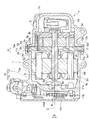
- FIG. 1 is a front sectional view showing an electric compressor according to an embodiment of the present invention.
- FIG. 2 is a front sectional view showing an electric compressor according to another embodiment of the present invention.
- FIG. 1 is a front sectional view showing an electric compressor according to an embodiment of the present invention.
- the electric compressor 1 of the present embodiment shown in FIG. 1 includes a compression mechanism 3 and an electric motor 5, and further includes an inverter circuit 9 that is a drive circuit for the electric motor 5, and the compression mechanism 3, the electric motor 5, and the inverter circuit 9. And the like.
- the compression mechanism 3 includes a pair of side blocks 3a and 3b, a cylinder block 3c sandwiched between them, and a columnar rotor 3e accommodated in an elliptical cylinder chamber 3d formed inside the cylinder block 3c. is doing.
- a plurality of vanes (not shown) are supported on the peripheral surface of the rotor 3e so as to appear and retract.
- the side block 3a is formed with a larger outer diameter than the side block 3b and the cylinder block 3c.
- the rotor 3e rotates in the cylinder chamber and compresses the refrigerant in the cylinder chamber.
- each vane of the rotor 3e appears and disappears following the inner peripheral surface of the cylinder chamber 3d, and the two vanes adjacent to the rotor 3e and the cylinder chamber 3d
- the volume of the configured space changes.
- the low-pressure refrigerant is sucked through the suction port 3f formed in the side block 3a, and the sucked refrigerant is compressed as the space volume decreases.
- the compressed high-pressure refrigerant is discharged from a discharge port (not shown) formed in the side block 3b.
- Each side block 3a, 3b is inserted from the side block 3b side having the same outer diameter as the cylinder block 3c in a state in which the rotor 3e is accommodated in the cylinder chamber 3d, passes through the cylinder block 3c, and is fastened to the side block 3a.
- the bolt 3g is fixed in close contact with both sides of the cylinder block 3c.
- the tip of the bolt 3g exposed on the motor case 11 side is located closer to the other surface 3a2 located on the cylinder block 3c side than the one surface 3a1 located on the motor case 11 side of the side block 3a.
- Rotating shaft 5a of electric motor 5 is connected to the center of rotor 3e.
- the rotating shaft 5a is supported by the penetrating portions of the side blocks 3a and 3b on both sides of the rotor 3e.
- the rotating shaft 5a penetrates the side block 3a of the compression mechanism 3 and protrudes outward from one surface 3a1.
- the portion of the rotating shaft 5 a that protrudes outside the compression mechanism 3 is fixed to the center of the columnar rotor 5 b of the electric motor 5.
- the arrow A in FIG. 1 shows the axial direction of the rotating shaft 5a
- the arrow B shows the radial direction of the rotating shaft 5a
- the line C shows the rotation center of the rotating shaft 5a, respectively.
- the housing 7 is made of, for example, an aluminum die-cast material, and includes a motor case 11 and a compressor case 13.
- the compressor case 13 of the housing 7 has a cylindrical shape with one end closed.
- An opening 13 b is formed in the end surface 13 a of the compressor case 13.
- the side block 3b and the cylinder block 3c of the compression mechanism 3 are accommodated except for the side block 3a having an outer diameter larger than the diameter of the opening 13b.
- a sealed discharge chamber 7 a is formed inside the compressor case 13 by the side block 3 b of the compression mechanism 3 and the bottom of the compressor case 13.
- the end surface 13a of the compressor case 13 is brought into contact with the other surface 3a2 located on the cylinder block 3c side of the side block 3a of the compression mechanism 3. By this contact, the opening 13b of the compressor case 13 is sealed with the other surface 3a2 of the side block 3a.
- a gasket 21 formed of an insulating material such as rubber.
- the flange part 13c extended from the opening 13b to the radial direction outer side of the rotating shaft 5a is formed in the end surface 13a of the compressor case 13. As shown in FIG.
- the flange portion 13c has the same outer diameter as that of the side block 3a, and is in contact with the other surface 3a2 of the side block 3a together with the end surface 13a.
- the motor case 11 of the housing 7 is configured by integrally connecting a motor housing portion 11a for housing the electric motor 5 and a circuit housing portion 11b with a partition wall 11c.
- the inside of the motor housing portion 11a constitutes a housing space for the electric motor 5 that also serves as the suction chamber 7b, and the inside of the circuit housing portion 11b constitutes a housing space 11d for the inverter circuit 9.
- the motor housing part 11a has an inner diameter larger than the inner diameter of the compressor case 13, and the motor housing part 11a has the same outer diameter as the flange part 13c of the compressor case 13 and the side block 3a of the compression mechanism 3. Is formed.
- the motor housing portion 11a has a bottomed cylindrical shape with the partition wall 11c as a bottom portion, and an opening 11e of the motor housing portion 11a is formed in an end surface 11f of the motor case 11.
- a stator 5c of the electric motor 5 is fixed inside the motor housing portion 11a.
- the rotor 5b described above is disposed inside the stator 5c fixed to the motor housing portion 11a.
- the rotor 5b is disposed so that the rotation center C of the rotation shaft 5a fixed to the center of the rotor 5b coincides with the center of the stator 5c.
- fixing of the stator 5c to the motor accommodating portion 11a is performed by shrink fitting.
- shrink fitting the motor case 11 is expanded by heating so that the inner diameter of the motor housing portion 11a is larger than the outer diameter of the stator 5c, and the stator 5c is moved along the axial direction A of the rotating shaft 5a. It is carried out by inserting the inside of the opening 11e and cooling the motor case 11 to room temperature.
- the outer peripheral surface of the stator 5c has a plurality of flat portions 5d at intervals in the rotation direction of the rotating shaft 5a.
- each flat portion 5d has a refrigerant passage gap S1 between the inner circumferential surface 11g of the motor housing 11a as shown in the lowermost part of FIG. Is formed.
- the outer peripheral surface portion between two adjacent flat portions 5d of the stator 5c is in contact with and in close contact with the inner peripheral surface 11g of the motor accommodating portion 11a as shown in the uppermost part of FIG.
- the arrangement of the rotor 5b inside the stator 5c fixed to the motor housing portion 11a is positioned on the motor case 11 side of the side block 3a of the compression mechanism 3 on the end surface 11f where the opening 11e of the motor housing portion 11a is formed. This is done by bringing one surface 3a1 into contact. By this contact, the opening 11e of the motor accommodating portion 11a is sealed with the surface 3a1 of the side block 3a.
- one surface of the side block 3a is inserted into the positioning holes 11j formed at a plurality of positions on the end surface 11f of the motor housing portion 11a.
- a plurality of positioning pins 17 erected from 3a1 are respectively inserted.
- a plurality of positioning pins 17 may be erected from the end surface 11f of the motor accommodating portion 11a, the positioning holes 11j may be formed in the one surface 3a1 of the side block 3a, and the positioning pins 17 may be inserted into the positioning holes 11j. .
- Each positioning hole 11j on the motor housing portion 11a side and each positioning pin 17 on the side block 3a side are inserted into each positioning pin 17 at a position corresponding to each positioning hole 11j, so that the rotation center of the rotating shaft 5a is rotated.
- C and the center of the stator 5c are configured to coincide with each other.
- each positioning hole 11j on the motor housing portion 11a side is formed at a position shifted from a position where the outer peripheral surface of the stator 5c contacts in the inner circumferential surface 11g of the motor housing portion 11a in the rotation direction X of the rotating shaft 5a. ing. In other words, each positioning hole 11j is in the same position as the position where the gap S1 is formed between each flat portion 5d of the stator 5c on the inner peripheral surface 11g of the motor housing portion 11a in the rotation direction X of the rotating shaft 5a. Is formed.
- the motor case 11a of the compressor case 13 and the motor case 11 that are in contact with the respective surfaces 3a1 and 3a2 of the side block 3a is inserted through the flange portion 13c of the compressor case 13 and penetrates the side block 3a, so that the motor case 11a.
- the bolts 15 are fastened to the surfaces 3a1 and 3a2 of the side block 3a so as to be in close contact with each other.
- the suction port 3f formed in the side block 3a is open to the lowermost part of the motor housing portion 11a that also serves as the suction chamber 7b on one surface 3a1 located on the motor case 11 side of the side block 3a. Further, the gap between the end surface 11f of the motor accommodating portion 11a and the surface 3a1 of the side block 3a is sealed by a gasket 19 formed of an insulating material such as rubber.
- the side block 3a of the compression mechanism 3 is disposed outside the compressor case 13 in which the side block 3b and the cylinder block 3c of the compression mechanism 3 are accommodated.
- the motor case 11 and the compressor case 13 in which the stator 5c of the electric motor 5 is fixed to the motor housing portion 11a are brought into contact with the pair of opposed surfaces 3a1 and 3a2 of the side block 3a, so that the side block 3a and the motor
- the case 11 and the compressor case 13 were connected and fixed to each other by fastening bolts 15.
- stator 5c fixed to the motor housing 11a of the motor case 11 and the rotating shaft 5a of the electric motor 5 supported by the side blocks 3a and 3b of the compression mechanism 3 are attached to the stator 5c. Centering with the rotor 5b arranged on the inner side can be easily performed only by positioning the motor case 11 with respect to the side block 3a of the compression mechanism 3.
- the motor case 11 for shrink fitting can be heated without any trouble.
- a plurality of positioning pins 17 erected from one surface 3a1 of the side block 3a are inserted into positioning holes 11j formed at a plurality of locations on the end surface 11f of the motor accommodating portion 11a.
- the side block 3a and the motor housing portion 11a can be easily positioned so that the rotation center C of the rotating shaft 5a and the center of the stator 5c coincide.
- each positioning hole 11j on the motor housing portion 11a side is placed in contact with the outer circumferential surface of the stator 5c in the inner circumferential surface 11g of the motor housing portion 11a in the rotational direction X of the rotating shaft 5a. The position was shifted from the contact point. That is, each positioning hole 11j is located at the same position in the rotational direction X of the rotating shaft 5a and the location where the gap S1 is formed between each flat portion 5d of the stator 5c on the inner peripheral surface 11g of the motor housing portion 11a. It is formed.
- the stator 5c does not come into contact with the inner peripheral surface 11g at a position where the gap S1 is formed between each flat portion 5d of the stator 5c. For this reason, even if the motor case 11 is heated and cooled when the stator 5c is shrink-fitted into the motor accommodating portion 11a, the motor accommodating portion having a larger thermal expansion coefficient than the stator 5c at the location where each positioning hole 11j is formed. 11a does not deform due to thermal contraction than the stator 5c, or even if the motor housing portion 11a is deformed, the degree thereof is small.
- the flange portion 13c extending to the outside of the opening 13b is formed on the end surface 13a of the compressor case 13 in which the side block 3b and the cylinder block 3c of the compression mechanism 3 are accommodated. And this flange part 13c was set as the structure attached with the volt
- the side block 3a of the compression mechanism 3 is disposed outside the compressor case 13, and the opening 11e of the motor housing portion 11a to which the stator 5c of the electric motor 5 is fixed serves as the side block 3a.
- the surface 3a1 is used for sealing.
- the suction port 3f for sucking the refrigerant in the suction chamber 7b into the cylinder chamber 3d of the compression mechanism 3 can be opened at the lowermost portion of the motor accommodating portion 11a that also serves as the suction chamber 7b. Therefore, it is possible to prevent a refrigerant pool having a liquid level lower than the opening of the suction port 3f from being generated in the suction chamber 7b.
- the bolt 3g which fixes each side block 3a, 3b of the compression mechanism 3 to the both sides of the cylinder block 3c is inserted from the side block 3b, the cylinder block 3c is penetrated, and a side block It was set as the structure fastened to 3a. For this reason, the part exposed to the motor accommodating part 11a of the volt
- the bolt head projecting from the surface 3a1 of the side block 3a to the compressor case 13 side avoids interference with the electric motor 5. Necessary. For this purpose, it is necessary to increase the depth of the motor housing portion 11a of the motor case 11 so that a gap larger than the axial dimension of the bolt head is formed between the electric motor 5 and the side block 3a.
- the motor case 11 can be reduced in size as a configuration in which the dimension of the motor housing portion 11a of the motor case 11 in the axial direction A of the rotating shaft 5a may be shortened.
- the bolt 3g is more than the cylinder block 3a. It is possible to prevent the insulation distance from the stator 5c from being shortened and to prevent the motor case 11 from becoming large in order to secure the insulation distance.
- the gasket 19 is provided not only between the end surface 11 f of the motor housing portion 11 a and the surface 3 a 1 of the side block 3 a but also the electric motor. 5 may be extended to the rotating shaft 5a side.
- the gasket 19 causes the stator 5c and the compression mechanism 3 side to be disposed. Insulation can be achieved.
- the insulation distance required between the compression mechanism 3 and the stator 5c in the axial direction A of the rotating shaft 5a is shortened, and the dimensions of the motor housing portion 11a of the motor case 11 in the axial direction A of the rotating shaft 5a are shortened.
- the motor case 11 can be further reduced in size.
- the present invention has a rotary compression mechanism that sucks and compresses gas by rotating a rotating body, such as a scroll compressor that rotates a movable scroll with respect to a fixed scroll to compress gas. This is widely applicable when the compressor is rotated by a motor.
- the present invention can be used in an electric compressor in which a refrigerant compression mechanism is driven by an electric motor.
Landscapes
- Engineering & Computer Science (AREA)
- Mechanical Engineering (AREA)
- General Engineering & Computer Science (AREA)
- Applications Or Details Of Rotary Compressors (AREA)
- Compressor (AREA)
Abstract
コンプレッサハウジング(13)の開口(13b)とモータハウジング(11)の開口(11e)とを封止する圧縮機構(3)の第2サイドブロック(3a)を、圧縮機構(3)の第1サイドブロック(3b)やシリンダブロック(3c)が収容されたコンプレッサハウジング(13)の外側に配置した。そして、第2サイドブロック(3a)の対向する一対の面(3a1,3a2)に、電動モータ(5)のステータ(5c)がモータハウジング(11a)に固定されたモータケース(11)とコンプレッサハウジング(13)とをそれぞれ当接させて、第2サイドブロック(3a)とモータケース(11)及びコンプレッサハウジング(13)とを相互に連結固定した。
Description
本発明は、冷媒を圧縮する冷凍サイクル用のコンプレッサに係り、特に、電動モータを動力源とする電動コンプレッサに関する。
冷凍サイクルに用いるコンプレッサは、低温低圧の冷媒を吸入し、圧縮により高温高圧とした冷媒を吐出する。コンプレッサの中には、冷媒の圧縮機構の動力源として電動モータを有する電動コンプレッサがある。電動コンプレッサでは、インバータにより電源からの直流電力を交流に変換して電動モータに供給する駆動回路が設けられる。
この種の電動コンプレッサでは、圧縮機構と電動モータとを収容するハウジングが、一般に、軽量で加工が容易なアルミニウム合金で形成される。このハウジングに電動モータを収容する際には、電動モータがハウジング内でガタ付くことのないようにする必要がある。そのためには、電動モータのステータをハウジングにガタ付きなく固定することが重要である。
ステータは一般に鉄製であり、ハウジングの素材であるアルミニウムとは熱膨張係数が異なる。このため、ハウジング内にステータをガタ付きなく固定するためには、ハウジングに対してステータを、圧入ではなく焼き嵌めによって固定することが望ましい。
ところで、圧縮機構の回転軸に取り付けられる電動モータのロータは、圧縮機構を介してハウジングに位置決めされる。このため、ハウジングに直接固定されるステータに対するロータの芯出し(センタリング)を行う必要がある。この芯出しを行うのに有利な構成として、圧縮機構をインロー固定したハウジングに、後から電動モータのステータを固定することが提案されている(特許文献1参照)。
しかし、このような構成を採用する場合には、圧縮機構が取り付けられた状態でハウジングを加熱するわけには行かないので、ステータをハウジングに収容する際に焼き嵌めを用いることができなくなってしまう。
そこで、圧縮機構と電動モータのステータとを別々のハウジングに取り付ける構造にすれば(特許文献2参照)、圧縮機構を取り付けたハウジングを加熱しなくても、電動モータのステータを焼き嵌めによってハウジングに取り付けることができる。
ところが、圧縮機構と電動モータのステータとを別々のハウジングに収容する構造では、ステータを焼き嵌めにより固定したハウジングを、圧縮機構を取り付けた別のハウジングに組み付けるので、それぞれのハウジングを経由して、圧縮機構側に連結された電動モータのロータと、ロータの外側に配置するステータとの芯出し(センタリング)を行わなければならない。したがって、芯出しの精度を出すのが難しく、芯出し作業に多くの手間がかかってしまう。
本発明は前記課題に鑑みなされたもので、本発明の目的は、電動モータのステータを焼き嵌めによりハウジングに固定することを実現しつつ、圧縮機構側に連結された電動モータのロータとステータとの芯出しを容易な作業で高精度に行うことができる電動コンプレッサを提供することにある。
本発明のある態様による電動コンプレッサは、冷媒を圧縮する圧縮機構と該圧縮機構を駆動する電動モータとをハウジングに収容した電動コンプレッサである。ハウジングは、圧縮機構を収容するコンプレッサハウジングと、電動モータのステータを内部に固定するモータハウジングとを有する。圧縮機構は、吸入した冷媒が圧縮されるシリンダ室を内部に有する筒状のシリンダブロックと、シリンダ室内で回転して該シリンダ室内の冷媒を圧縮する回転体と、シリンダブロックの両側部にそれぞれ取り付けられ、各側部においてシリンダ室を封止する一対のサイドブロックとを有する。一対のサイドブロックのうち第1サイドブロック及びシリンダブロックが内部に収容されたコンプレッサハウジングの開口と、電動モータが内部に収容されたモータハウジングの開口とが、それら両開口よりも大きい径で形成された、一対のサイドブロックのうち第2サイドブロックの互いに対向する一対の面でそれぞれ封止される。第2サイドブロックの一対の面間を貫通して該第2サイドブロックにより軸受けされた電動モータの回転軸が、シリンダ室内の回転体に接続されている。
本発明のある態様による電動コンプレッサによれば、電動モータのステータを焼き嵌めによりハウジングに固定することを実現しつつ、圧縮機構側に連結された電動モータのロータとステータとの芯出しを容易な作業で高精度に行うことができる。
以下、本発明の実施形態について図面を参照しながら説明する。図1は本発明の一実施形態に係る電動コンプレッサを示す正断面図である。
図1に示す本実施形態の電動コンプレッサ1は、圧縮機構3及び電動モータ5を有し、さらに、電動モータ5の駆動回路であるインバータ回路9と、圧縮機構3、電動モータ5及びインバータ回路9等が収容されるハウジング7とを有している。
圧縮機構3は、一対のサイドブロック3a,3bと、これらによって挟持されたシリンダブロック3cと、シリンダブロック3cの内部に形成された楕円形のシリンダ室3dに収容した円柱状のロータ3eとを有している。ロータ3eの周面には、複数のベーン(図示せず)が出没可能に支持されている。サイドブロック3aは、サイドブロック3bやシリンダブロック3cよりも大きい外径で形成されている。
ロータ3eは、シリンダ室内で回転して該シリンダ室内の冷媒を圧縮する。ロータ3eが電動モータ5によりシリンダ室3d内で回転されると、ロータ3eの各ベーンがシリンダ室3dの内周面に倣って出没し、ロータ3eと隣り合う2つのベーンとシリンダ室3dとで構成される空間の容積が変化する。
そして、空間の容積が増加する間に、サイドブロック3aに形成した吸入口3fを通じて低圧の冷媒が吸入され、吸入された冷媒が、空間の容積の減少に伴い圧縮される。圧縮された高圧の冷媒は、サイドブロック3bに形成した吐出口(図示せず)から吐出される。
各サイドブロック3a,3bは、シリンダ室3dにロータ3eを収容した状態で、シリンダブロック3cと同じ外径のサイドブロック3b側から挿入されてシリンダブロック3cを貫通し、サイドブロック3aに締結されるボルト3gによって、シリンダブロック3cの両側に密着した状態で固定される。
モータケース11側に露出するボルト3gの先端は、サイドブロック3aのモータケース11側に位置する一方の面3a1よりも、シリンダブロック3c側に位置する他方の面3a2寄りに位置している。
ロータ3eの中心には、電動モータ5の回転軸5aが接続されている。この回転軸5aは、ロータ3eの両側で、各サイドブロック3a,3bの貫通箇所によって軸受けされている。回転軸5aは、圧縮機構3のサイドブロック3aを貫通して一方の面3a1から外側に突出している。回転軸5aの圧縮機構3の外側に突出した部分は、電動モータ5の円柱状のロータ5bの中心に固定されている。
なお、図1中の矢印Aは回転軸5aの軸方向、矢印Bは回転軸5aの径方向、線Cは回転軸5aの回転中心をそれぞれ示す。
ハウジング7は、例えばアルミダイカスト材で形成されており、モータケース11とコンプレッサケース13を有している。
ハウジング7のコンプレッサケース13は、一端が閉塞された円筒状を呈している。このコンプレッサケース13の端面13aには開口13bが形成されている。コンプレッサケース13の内部には、開口13bの径よりも大きい外径のサイドブロック3aを除く、圧縮機構3のサイドブロック3bやシリンダブロック3cが収容される。
そして、圧縮機構3のサイドブロック3bとコンプレッサケース13の底部とにより、密閉された吐出室7aがコンプレッサケース13の内部に形成されている。
コンプレッサケース13の端面13aは、圧縮機構3のサイドブロック3aのシリンダブロック3c側に位置する他方の面3a2に当接される。この当接により、コンプレッサケース13の開口13bはサイドブロック3aの他方の面3a2で封止される。
また、コンプレッサケース13の端面13aとサイドブロック3aの他方の面3a2との間は、ゴム等の絶縁材料によって形成されたガスケット21によってシールされる。
コンプレッサケース13の端面13aには、開口13bから回転軸5aの径方向外側に延出するフランジ部13cが形成されている。フランジ部13cは、サイドブロック3aと同じ外径を有しており、端面13aと共にサイドブロック3aの他方の面3a2に当接される。
また、ハウジング7のモータケース11は、電動モータ5を内部に収容するモータ収容部11aと回路収容部11bとを、仕切壁11cにより一体に接続して構成されている。モータ収容部11aの内部は、吸入室7bを兼ねる電動モータ5の収容空間を構成し、回路収容部11bの内部は、インバータ回路9の収容空間11dを構成する。
モータ収容部11aは、コンプレッサケース13の内径よりも大きい内径を有しており、モータ収容部11aの外径は、コンプレッサケース13のフランジ部13cや圧縮機構3のサイドブロック3aと同じ外径で形成されている。
このモータ収容部11aは、仕切壁11cを底部とする有底の円筒状を呈しており、モータ収容部11aの開口11eは、モータケース11の端面11fに形成されている。モータ収容部11aの内部には、電動モータ5のステータ5cが固定される。
モータ収容部11aに固定したステータ5cの内側には、上述したロータ5bが配置される。ロータ5bは、ロータ5bの中心に固定した回転軸5aの回転中心Cがステータ5cの中心と一致するように配置される。
ここで、モータ収容部11aへのステータ5cの固定は、焼き嵌めによって行われる。焼き嵌めは、モータ収容部11aの内径がステータ5cの外径よりも大きくなるようにモータケース11を加熱により膨張させて、回転軸5aの軸方向Aに沿ってステータ5cをモータ収容部11aの開口11eから内部に挿入し、モータケース11を常温に冷却させることで行われる。
ステータ5cの外周面は、回転軸5aの回転方向に間隔をおいて複数の平坦部5dを有している。各平坦部5dは、ステータ5cを焼き嵌めによりモータ収容部11aに固定すると、図1の最下部に示すように、モータ収容部11aの内周面11gとの間に、冷媒通過用の隙間S1が形成される。ステータ5cの隣り合う2つの平坦部5d間の外周面部分は、図1の最上部に示すように、モータ収容部11aの内周面11gに当接し密着する。
また、モータ収容部11aに固定したステータ5cの内側へのロータ5bの配置は、モータ収容部11aの開口11eが形成された端面11fに、圧縮機構3のサイドブロック3aのモータケース11側に位置する一方の面3a1を当接させることで行われる。この当接により、モータ収容部11aの開口11eはサイドブロック3aの面3a1で封止される。
モータ収容部11aの端面11fにサイドブロック3aの一方の面3a1を当接させる際には、モータ収容部11aの端面11fの複数箇所に形成された位置決め孔11jに、サイドブロック3aの一方の面3a1から立設した複数の位置決めピン17が、それぞれ挿入される。勿論、モータ収容部11aの端面11fから複数の位置決めピン17を立設し、サイドブロック3aの一方の面3a1に位置決め孔11jを形成して、位置決めピン17を位置決め孔11jに挿入しても良い。
モータ収容部11a側の各位置決め孔11jと、サイドブロック3a側の各位置決めピン17とは、各位置決め孔11jに対応する位置の各位置決めピン17をそれぞれ挿入することで、回転軸5aの回転中心Cとステータ5cの中心とが一致するように構成されている。
なお、モータ収容部11a側の各位置決め孔11jは、回転軸5aの回転方向Xにおいて、モータ収容部11aの内周面11gのうちステータ5cの外周面が当接する箇所から位置をずらして形成されている。言い換えると、各位置決め孔11jは、回転軸5aの回転方向Xにおいて、モータ収容部11aの内周面11gのうちステータ5cの各平坦部5dとの間に隙間S1が形成される箇所と同じ位置に形成されている。
サイドブロック3aの各面3a1,3a2にそれぞれ当接されたコンプレッサケース13及びモータケース11のモータ収容部11aは、コンプレッサケース13のフランジ部13cから挿通されてサイドブロック3aを貫通しモータ収容部11aに締結されるボルト15によって、サイドブロック3aの各面3a1,3a2に密着した状態に固定される。
なお、サイドブロック3aに形成した吸入口3fは、サイドブロック3aのモータケース11側に位置する一方の面3a1において、吸入室7bを兼ねるモータ収容部11aの最下部に開口している。また、モータ収容部11aの端面11fとサイドブロック3aの面3a1との間は、ゴム等の絶縁材料によって形成されたガスケット19によってシールされる。
このように構成した本実施形態の電動コンプレッサ1では、圧縮機構3のサイドブロック3aを、圧縮機構3のサイドブロック3bやシリンダブロック3cが収容されたコンプレッサケース13の外側に配置した。そして、サイドブロック3aの対向する一対の面3a1,3a2に、電動モータ5のステータ5cがモータ収容部11aに固定されたモータケース11とコンプレッサケース13とを当接させて、サイドブロック3aとモータケース11及びコンプレッサケース13とを、ボルト15の締結により相互に連結固定した。
このため、モータケース11のモータ収容部11aに固定された電動モータ5のステータ5cと、圧縮機構3のサイドブロック3a,3bに軸受けされた電動モータ5の回転軸5aに取り付けられてステータ5cの内側に配置されるロータ5bとの芯出しを、圧縮機構3のサイドブロック3aに対してモータケース11を位置決めするだけで容易に行うことができる。
しかも、ステータ5cを焼き嵌めによってモータ収容部11aに固定する前に、モータケース11に圧縮機構3を取り付ける必要がないので、焼き嵌めのためのモータケース11の加熱を支障なく行うことができる。
また、本実施形態の電動コンプレッサ1では、サイドブロック3aの一方の面3a1から立設した複数の位置決めピン17を、モータ収容部11aの端面11fの複数箇所に形成された位置決め孔11jに挿入することで、回転軸5aの回転中心Cとステータ5cの中心とが一致するようにサイドブロック3aとモータ収容部11aとを容易に位置決めすることができる。
さらに、本実施形態の電動コンプレッサ1では、モータ収容部11a側の各位置決め孔11jを、回転軸5aの回転方向Xにおいて、モータ収容部11aの内周面11gのうちステータ5cの外周面が当接する箇所から位置をずらして形成した。即ち、各位置決め孔11jは、モータ収容部11aの内周面11gのうちステータ5cの各平坦部5dとの間に隙間S1が形成される箇所と、回転軸5aの回転方向Xにおいて同じ位置に形成される。
モータ収容部11aの内周面11gのうちステータ5cの各平坦部5dとの間に隙間S1が形成される箇所では、ステータ5cが内周面11gに当接しない。このため、ステータ5cをモータ収容部11aに焼き嵌めする際にモータケース11を加熱、冷却しても、各位置決め孔11jが形成される箇所では、ステータ5cよりも熱膨張係数が大きいモータ収容部11aが、ステータ5cよりも熱収縮して変形することがないか、万一、モータ収容部11aが変形したとしても、その度合いはわずかなものとなる。
したがって、各位置決め孔11jへの各位置決めピン17の挿入による回転軸5aとステータ5cとの芯出しの精度を、高く維持することができる。
また、本実施形態の電動コンプレッサ1では、圧縮機構3のサイドブロック3bやシリンダブロック3cが収容されたコンプレッサケース13の端面13aに、開口13bの外側に延出するフランジ部13cを形成した。そして、このフランジ部13cを、コンプレッサケース13の開口13bよりも径が大きい圧縮機構3のサイドブロック3aにボルト15で取り付ける構成とした。
このため、モータケース11のモータ収容部11aの外径に合わせてコンプレッサケース13の外径を必要以上に大きくする必要をなくし、コンプレッサケース13の小型化を図ることができる。
さらに、本実施形態の電動コンプレッサ1では、圧縮機構3のサイドブロック3aをコンプレッサケース13の外側に配置して、電動モータ5のステータ5cが固定されるモータ収容部11aの開口11eをサイドブロック3aの面3a1によって封止する構成とした。
このため、圧縮機構3のシリンダ室3dに吸入室7bの冷媒を吸入する吸入口3fを、吸入室7bを兼ねるモータ収容部11aの最下部に開口させることができる。よって、吸入口3fの開口よりも低い液面の冷媒溜まりが吸入室7bに発生するのを防止することができる。
また、本実施形態の電動コンプレッサ1では、圧縮機構3の各サイドブロック3a,3bをシリンダブロック3cの両側に固定するボルト3gを、サイドブロック3bから挿入してシリンダブロック3cを貫通させ、サイドブロック3aに締結させる構成とした。このため、ボルト3gのモータ収容部11aに露出する部分が、径の大きい頭部ではなく径の小さい先端となる。
もし仮に、圧縮機構3の締結用のボルトをサイドブロック3a側から挿入する構成とすると、サイドブロック3aの面3a1からコンプレッサケース13側に突出するボルト頭部の電動モータ5に対する干渉避けの構成が必要となる。それには、電動モータ5とサイドブロック3aとの間にボルト頭部の軸方向寸法以上の隙間が形成されるように、モータケース11のモータ収容部11aの奥行きを大きくする必要がある。
しかし、サイドブロック3b側からボルト3gを挿入する構成とすれば、サイドブロック3bに隣接する吐出室7aがボルト3gの干渉避けの空間となるので、モータケース11側に干渉避け空間を確保する必要がなくなる。よって、回転軸5aの軸方向Aにおけるモータケース11のモータ収容部11aの寸法を短くしてもよい構成として、モータケース11の小型化を図ることができる。
その上、ボルト3gの先端を、サイドブロック3aのモータケース11側に位置する一方の面3a1よりもシリンダブロック3c側の面3a2寄りに位置させたので、ボルト3gの方がシリンダブロック3aよりもステータ5cとの絶縁距離が短くなるのを防ぎ、絶縁距離確保のためにモータケース11が大型化してしまうのを避けることができる。
なお、図2の正断面図に示す他の実施形態に係る電動コンプレッサ1のように、ガスケット19を、モータ収容部11aの端面11fとサイドブロック3aの面3a1との間だけでなく、電動モータ5の回転軸5a側に延長して配置するようにしてもよい。
このとき、回転軸5aの径方向Bにおいて、少なくとも電動モータ5のステータ5cが存在する部分の全体に亘ってガスケット19が配置されるようにすれば、ガスケット19によりステータ5cと圧縮機構3側との絶縁を図ることができる。
したがって、回転軸5aの軸方向Aにおいて圧縮機構3とステータ5cとの間に必要となる絶縁距離を短くして、回転軸5aの軸方向Aにおけるモータケース11のモータ収容部11aの寸法を短くできる構成とし、モータケース11のさらなる小型化を図ることができる。
なお、以上の実施形態では、シリンダ室3d内でロータ3eを回転させるベーンロータリー式の圧縮機構3を有する電動コンプレッサ1に本発明を適用した場合を例に取って説明した。
しかし、本発明は、例えば、可動スクロールを固定スクロールに対して回転させて気体を圧縮するスクロール方式のコンプレッサ等、回転体を回転させることで気体を吸入して圧縮する回転式の圧縮機構を有するコンプレッサをモータで回転させる場合に広く適用可能である。
本発明は、冷媒の圧縮機構を電動モータで駆動する電動コンプレッサにおいて利用することができる。
1 電動コンプレッサ 3 圧縮機構 3a サイドブロック 3b サイドブロック 3a1 サイドブロック3aのモータケース側の面 3a2 サイドブロック3aのシリンダブロック側の面 3c シリンダブロック 3d シリンダ室 3e ロータ 3f 吸入口 3g ボルト 5 電動モータ 5a 回転軸 5b ロータ 5c ステータ 5d 平坦部 7 ハウジング 7a 吐出室 7b 吸入室 9 インバータ回路 11 モータケース 11a モータ収容部 11b 回路収容部 11c 仕切壁 11d インバータ回路収容空間 11e モータ収容部開口 11f モータケース端面 11g モータ収容部内周面 11h 回路収容部開口 11i キャップ 11j 位置決め孔 13 コンプレッサケース 13a コンプレッサケース端面 13b コンプレッサケース開口 15 ボルト 17 位置決めピン 19 ガスケット A 回転軸の軸方向 B 回転軸の径方向 C 回転軸の回転中心 S1 隙間
Claims (6)
- 冷媒を圧縮する圧縮機構と該圧縮機構を駆動する電動モータとをハウジングに収容した電動コンプレッサであって、
前記ハウジングは、前記圧縮機構を収容するコンプレッサハウジングと、前記電動モータのステータを内部に固定するモータハウジングとを有しており、
前記圧縮機構は、吸入した冷媒が圧縮されるシリンダ室を内部に有する筒状のシリンダブロックと、前記シリンダ室内で回転して該シリンダ室内の冷媒を圧縮する回転体と、前記シリンダブロックの両側部にそれぞれ取り付けられ、各側部において前記シリンダ室を封止する一対のサイドブロックとを有しており、
前記一対のサイドブロックのうち第1サイドブロック及び前記シリンダブロックが内部に収容された前記コンプレッサハウジングの開口と、前記電動モータが内部に収容された前記モータハウジングの開口とが、それら両開口よりも大きい径で形成された、前記一対のサイドブロックのうち第2サイドブロックの互いに対向する一対の面にそれぞれ当接して封止され、
前記第2サイドブロックの前記一対の面間を貫通して該第2サイドブロックにより軸受けされた前記電動モータの回転軸が、前記シリンダ室内の前記回転体に接続されている、
電動コンプレッサ。 - 前記モータハウジングの前記開口を封止する前記第2サイドブロックの一方の面に、前記回転軸の回転中心と前記ステータの中心とを一致させるための位置決めピンと、該複数の位置決めピンがそれぞれ挿入される複数の位置決め孔とのうち、いずれか一方が設けられており、
前記モータハウジングの前記開口を有する端面に、前記複数の位置決めピンと前記複数の位置決め孔とのうち、いずれか他方が設けられており、
前記各位置決め孔は、前記モータハウジングの内周面における、前記電動モータのステータが前記回転軸の回転方向に間隔をおいてそれぞれ当接する箇所に対して、前記回転方向に位置をずらして形成されている、
請求項1記載の電動コンプレッサ。 - 前記コンプレッサハウジングは、前記第2サイドブロック及び前記モータハウジングよりも小さい外径で形成されており、前記コンプレッサハウジングの前記開口を有する端面には、前記開口から前記回転軸の径方向外側に延出するフランジ部が形成されており、前記第2サイドブロックを貫通するハウジング締結部材によって前記フランジ部と前記モータハウジングとが締結されている請求項1又は2記載の電動コンプレッサ。
- 前記第2サイドブロックは、前記一対の面間を貫通して前記モータハウジング内の吸入室に吸入された冷媒を前記シリンダ室に導入する吸入口を有しており、該吸入口は、前記モータハウジングの前記開口を封止する前記第2サイドブロックの一方の面における、前記吸入室の最下部に臨む箇所に開口している請求項1、2又は3記載の電動コンプレッサ。
- 前記モータハウジングの前記開口を有する端面、該開口を封止する前記第2サイドブロックの一方の面との間は、両者間に介設された絶縁材料製のガスケットによりシールされており、該ガスケットは、前記回転軸の径方向において、少なくとも前記電動モータのステータの存在部分以上の範囲に延在している請求項1、2、3又は4記載の電動コンプレッサ。
- 前記圧縮機構は、前記第1サイドブロックから挿入されて前記シリンダブロックを貫通し前記第2サイドブロックに締結される圧縮機構締結部材を有している請求項1、2、3、4又は5記載の電動コンプレッサ。
Applications Claiming Priority (2)
| Application Number | Priority Date | Filing Date | Title |
|---|---|---|---|
| JP2016-135099 | 2016-07-07 | ||
| JP2016135099A JP2018003792A (ja) | 2016-07-07 | 2016-07-07 | 電動コンプレッサ |
Publications (1)
| Publication Number | Publication Date |
|---|---|
| WO2018008553A1 true WO2018008553A1 (ja) | 2018-01-11 |
Family
ID=60901728
Family Applications (1)
| Application Number | Title | Priority Date | Filing Date |
|---|---|---|---|
| PCT/JP2017/024179 Ceased WO2018008553A1 (ja) | 2016-07-07 | 2017-06-30 | 電動コンプレッサ |
Country Status (2)
| Country | Link |
|---|---|
| JP (1) | JP2018003792A (ja) |
| WO (1) | WO2018008553A1 (ja) |
Families Citing this family (2)
| Publication number | Priority date | Publication date | Assignee | Title |
|---|---|---|---|---|
| JP2018168770A (ja) * | 2017-03-30 | 2018-11-01 | 株式会社豊田自動織機 | 電動圧縮機 |
| JP7182430B2 (ja) * | 2018-10-30 | 2022-12-02 | サンデン株式会社 | 電動圧縮機 |
Citations (5)
| Publication number | Priority date | Publication date | Assignee | Title |
|---|---|---|---|---|
| JPS53114507A (en) * | 1977-03-17 | 1978-10-06 | Nippon Carbureter | Vacuum pump directly coupled to alternator |
| JPS59196986A (ja) * | 1983-04-20 | 1984-11-08 | Mitsubishi Electric Corp | ロ−ラベ−ンポンプ |
| JP2005291038A (ja) * | 2004-03-31 | 2005-10-20 | Denso Corp | 流体機械用の切替え弁構造 |
| JP2011122541A (ja) * | 2009-12-11 | 2011-06-23 | Denso Corp | ベーン式ポンプおよびそれを用いたエバポリークチェックシステム |
| WO2016084874A1 (ja) * | 2014-11-28 | 2016-06-02 | 株式会社豊田自動織機 | ベーン型圧縮機 |
-
2016
- 2016-07-07 JP JP2016135099A patent/JP2018003792A/ja active Pending
-
2017
- 2017-06-30 WO PCT/JP2017/024179 patent/WO2018008553A1/ja not_active Ceased
Patent Citations (5)
| Publication number | Priority date | Publication date | Assignee | Title |
|---|---|---|---|---|
| JPS53114507A (en) * | 1977-03-17 | 1978-10-06 | Nippon Carbureter | Vacuum pump directly coupled to alternator |
| JPS59196986A (ja) * | 1983-04-20 | 1984-11-08 | Mitsubishi Electric Corp | ロ−ラベ−ンポンプ |
| JP2005291038A (ja) * | 2004-03-31 | 2005-10-20 | Denso Corp | 流体機械用の切替え弁構造 |
| JP2011122541A (ja) * | 2009-12-11 | 2011-06-23 | Denso Corp | ベーン式ポンプおよびそれを用いたエバポリークチェックシステム |
| WO2016084874A1 (ja) * | 2014-11-28 | 2016-06-02 | 株式会社豊田自動織機 | ベーン型圧縮機 |
Also Published As
| Publication number | Publication date |
|---|---|
| JP2018003792A (ja) | 2018-01-11 |
Similar Documents
| Publication | Publication Date | Title |
|---|---|---|
| US10221852B2 (en) | Multi stage scroll vacuum pumps and related scroll devices | |
| JP2021120542A (ja) | 電動圧縮機 | |
| KR20170113153A (ko) | 유체 기계 | |
| JP5007169B2 (ja) | 電動コンプレッサ | |
| EP3176437A1 (en) | Enclosed compressdor and refrigeration device | |
| JPWO2019026340A1 (ja) | 真空ポンプ | |
| US9885359B2 (en) | Motor-driven compressor | |
| JP2018003792A (ja) | 電動コンプレッサ | |
| US20190264687A1 (en) | Scroll compressor and refrigeration cycle apparatus | |
| JP2016217291A (ja) | 電動コンプレッサ及びその製造方法 | |
| KR102427373B1 (ko) | 밀폐형 압축기, 및 밀폐형 압축기의 제조 방법 | |
| EP3550147B1 (en) | Compressor system | |
| JP2016037906A (ja) | 高圧ドーム型圧縮機 | |
| JP2010255600A (ja) | 二段スクリュー圧縮機 | |
| JP2014227919A (ja) | 圧縮機 | |
| KR102321486B1 (ko) | 스크롤 압축기 및 스크롤 압축기 제조방법 | |
| WO2020235271A1 (ja) | スクロール圧縮機およびそれを備えた冷凍装置 | |
| EP3141754B1 (en) | Rotary compressor and method for manufacturing the same | |
| US20150125322A1 (en) | Rotary compressor | |
| JP6596787B2 (ja) | スクロール圧縮機 | |
| KR102825794B1 (ko) | 전동압축기 | |
| WO2003083308A1 (en) | Rotary compressor | |
| JP2019183702A (ja) | 圧縮機システム | |
| KR101161440B1 (ko) | 로터리 압축기 | |
| JP2008196317A (ja) | 電動コンプレッサ |
Legal Events
| Date | Code | Title | Description |
|---|---|---|---|
| 121 | Ep: the epo has been informed by wipo that ep was designated in this application |
Ref document number: 17824157 Country of ref document: EP Kind code of ref document: A1 |
|
| NENP | Non-entry into the national phase |
Ref country code: DE |
|
| 122 | Ep: pct application non-entry in european phase |
Ref document number: 17824157 Country of ref document: EP Kind code of ref document: A1 |