WO2018003724A1 - Battery and method for producing positive electrode for same - Google Patents
Battery and method for producing positive electrode for same Download PDFInfo
- Publication number
- WO2018003724A1 WO2018003724A1 PCT/JP2017/023338 JP2017023338W WO2018003724A1 WO 2018003724 A1 WO2018003724 A1 WO 2018003724A1 JP 2017023338 W JP2017023338 W JP 2017023338W WO 2018003724 A1 WO2018003724 A1 WO 2018003724A1
- Authority
- WO
- WIPO (PCT)
- Prior art keywords
- battery
- continuum
- positive electrode
- metal
- oxide
- Prior art date
Links
Images


Classifications
-
- H—ELECTRICITY
- H01—ELECTRIC ELEMENTS
- H01M—PROCESSES OR MEANS, e.g. BATTERIES, FOR THE DIRECT CONVERSION OF CHEMICAL ENERGY INTO ELECTRICAL ENERGY
- H01M12/00—Hybrid cells; Manufacture thereof
- H01M12/08—Hybrid cells; Manufacture thereof composed of a half-cell of a fuel-cell type and a half-cell of the secondary-cell type
-
- C—CHEMISTRY; METALLURGY
- C04—CEMENTS; CONCRETE; ARTIFICIAL STONE; CERAMICS; REFRACTORIES
- C04B—LIME, MAGNESIA; SLAG; CEMENTS; COMPOSITIONS THEREOF, e.g. MORTARS, CONCRETE OR LIKE BUILDING MATERIALS; ARTIFICIAL STONE; CERAMICS; REFRACTORIES; TREATMENT OF NATURAL STONE
- C04B35/00—Shaped ceramic products characterised by their composition; Ceramics compositions; Processing powders of inorganic compounds preparatory to the manufacturing of ceramic products
- C04B35/515—Shaped ceramic products characterised by their composition; Ceramics compositions; Processing powders of inorganic compounds preparatory to the manufacturing of ceramic products based on non-oxide ceramics
- C04B35/52—Shaped ceramic products characterised by their composition; Ceramics compositions; Processing powders of inorganic compounds preparatory to the manufacturing of ceramic products based on non-oxide ceramics based on carbon, e.g. graphite
- C04B35/522—Graphite
-
- C—CHEMISTRY; METALLURGY
- C01—INORGANIC CHEMISTRY
- C01B—NON-METALLIC ELEMENTS; COMPOUNDS THEREOF; METALLOIDS OR COMPOUNDS THEREOF NOT COVERED BY SUBCLASS C01C
- C01B32/00—Carbon; Compounds thereof
- C01B32/15—Nano-sized carbon materials
- C01B32/182—Graphene
-
- C—CHEMISTRY; METALLURGY
- C04—CEMENTS; CONCRETE; ARTIFICIAL STONE; CERAMICS; REFRACTORIES
- C04B—LIME, MAGNESIA; SLAG; CEMENTS; COMPOSITIONS THEREOF, e.g. MORTARS, CONCRETE OR LIKE BUILDING MATERIALS; ARTIFICIAL STONE; CERAMICS; REFRACTORIES; TREATMENT OF NATURAL STONE
- C04B35/00—Shaped ceramic products characterised by their composition; Ceramics compositions; Processing powders of inorganic compounds preparatory to the manufacturing of ceramic products
- C04B35/622—Forming processes; Processing powders of inorganic compounds preparatory to the manufacturing of ceramic products
- C04B35/626—Preparing or treating the powders individually or as batches ; preparing or treating macroscopic reinforcing agents for ceramic products, e.g. fibres; mechanical aspects section B
- C04B35/62605—Treating the starting powders individually or as mixtures
- C04B35/62645—Thermal treatment of powders or mixtures thereof other than sintering
- C04B35/62655—Drying, e.g. freeze-drying, spray-drying, microwave or supercritical drying
-
- C—CHEMISTRY; METALLURGY
- C04—CEMENTS; CONCRETE; ARTIFICIAL STONE; CERAMICS; REFRACTORIES
- C04B—LIME, MAGNESIA; SLAG; CEMENTS; COMPOSITIONS THEREOF, e.g. MORTARS, CONCRETE OR LIKE BUILDING MATERIALS; ARTIFICIAL STONE; CERAMICS; REFRACTORIES; TREATMENT OF NATURAL STONE
- C04B35/00—Shaped ceramic products characterised by their composition; Ceramics compositions; Processing powders of inorganic compounds preparatory to the manufacturing of ceramic products
- C04B35/622—Forming processes; Processing powders of inorganic compounds preparatory to the manufacturing of ceramic products
- C04B35/626—Preparing or treating the powders individually or as batches ; preparing or treating macroscopic reinforcing agents for ceramic products, e.g. fibres; mechanical aspects section B
- C04B35/628—Coating the powders or the macroscopic reinforcing agents
- C04B35/62844—Coating fibres
- C04B35/62847—Coating fibres with oxide ceramics
-
- C—CHEMISTRY; METALLURGY
- C04—CEMENTS; CONCRETE; ARTIFICIAL STONE; CERAMICS; REFRACTORIES
- C04B—LIME, MAGNESIA; SLAG; CEMENTS; COMPOSITIONS THEREOF, e.g. MORTARS, CONCRETE OR LIKE BUILDING MATERIALS; ARTIFICIAL STONE; CERAMICS; REFRACTORIES; TREATMENT OF NATURAL STONE
- C04B35/00—Shaped ceramic products characterised by their composition; Ceramics compositions; Processing powders of inorganic compounds preparatory to the manufacturing of ceramic products
- C04B35/622—Forming processes; Processing powders of inorganic compounds preparatory to the manufacturing of ceramic products
- C04B35/626—Preparing or treating the powders individually or as batches ; preparing or treating macroscopic reinforcing agents for ceramic products, e.g. fibres; mechanical aspects section B
- C04B35/628—Coating the powders or the macroscopic reinforcing agents
- C04B35/62892—Coating the powders or the macroscopic reinforcing agents with a coating layer consisting of particles
-
- C—CHEMISTRY; METALLURGY
- C04—CEMENTS; CONCRETE; ARTIFICIAL STONE; CERAMICS; REFRACTORIES
- C04B—LIME, MAGNESIA; SLAG; CEMENTS; COMPOSITIONS THEREOF, e.g. MORTARS, CONCRETE OR LIKE BUILDING MATERIALS; ARTIFICIAL STONE; CERAMICS; REFRACTORIES; TREATMENT OF NATURAL STONE
- C04B38/00—Porous mortars, concrete, artificial stone or ceramic ware; Preparation thereof
- C04B38/0045—Porous mortars, concrete, artificial stone or ceramic ware; Preparation thereof by a process involving the formation of a sol or a gel, e.g. sol-gel or precipitation processes
-
- H—ELECTRICITY
- H01—ELECTRIC ELEMENTS
- H01M—PROCESSES OR MEANS, e.g. BATTERIES, FOR THE DIRECT CONVERSION OF CHEMICAL ENERGY INTO ELECTRICAL ENERGY
- H01M12/00—Hybrid cells; Manufacture thereof
- H01M12/04—Hybrid cells; Manufacture thereof composed of a half-cell of the fuel-cell type and of a half-cell of the primary-cell type
- H01M12/06—Hybrid cells; Manufacture thereof composed of a half-cell of the fuel-cell type and of a half-cell of the primary-cell type with one metallic and one gaseous electrode
-
- H—ELECTRICITY
- H01—ELECTRIC ELEMENTS
- H01M—PROCESSES OR MEANS, e.g. BATTERIES, FOR THE DIRECT CONVERSION OF CHEMICAL ENERGY INTO ELECTRICAL ENERGY
- H01M4/00—Electrodes
- H01M4/86—Inert electrodes with catalytic activity, e.g. for fuel cells
-
- H—ELECTRICITY
- H01—ELECTRIC ELEMENTS
- H01M—PROCESSES OR MEANS, e.g. BATTERIES, FOR THE DIRECT CONVERSION OF CHEMICAL ENERGY INTO ELECTRICAL ENERGY
- H01M4/00—Electrodes
- H01M4/86—Inert electrodes with catalytic activity, e.g. for fuel cells
- H01M4/8647—Inert electrodes with catalytic activity, e.g. for fuel cells consisting of more than one material, e.g. consisting of composites
- H01M4/8652—Inert electrodes with catalytic activity, e.g. for fuel cells consisting of more than one material, e.g. consisting of composites as mixture
-
- H—ELECTRICITY
- H01—ELECTRIC ELEMENTS
- H01M—PROCESSES OR MEANS, e.g. BATTERIES, FOR THE DIRECT CONVERSION OF CHEMICAL ENERGY INTO ELECTRICAL ENERGY
- H01M4/00—Electrodes
- H01M4/86—Inert electrodes with catalytic activity, e.g. for fuel cells
- H01M4/88—Processes of manufacture
- H01M4/8825—Methods for deposition of the catalytic active composition
- H01M4/8842—Coating using a catalyst salt precursor in solution followed by evaporation and reduction of the precursor
-
- H—ELECTRICITY
- H01—ELECTRIC ELEMENTS
- H01M—PROCESSES OR MEANS, e.g. BATTERIES, FOR THE DIRECT CONVERSION OF CHEMICAL ENERGY INTO ELECTRICAL ENERGY
- H01M4/00—Electrodes
- H01M4/86—Inert electrodes with catalytic activity, e.g. for fuel cells
- H01M4/90—Selection of catalytic material
-
- H—ELECTRICITY
- H01—ELECTRIC ELEMENTS
- H01M—PROCESSES OR MEANS, e.g. BATTERIES, FOR THE DIRECT CONVERSION OF CHEMICAL ENERGY INTO ELECTRICAL ENERGY
- H01M4/00—Electrodes
- H01M4/86—Inert electrodes with catalytic activity, e.g. for fuel cells
- H01M4/90—Selection of catalytic material
- H01M4/9016—Oxides, hydroxides or oxygenated metallic salts
-
- H—ELECTRICITY
- H01—ELECTRIC ELEMENTS
- H01M—PROCESSES OR MEANS, e.g. BATTERIES, FOR THE DIRECT CONVERSION OF CHEMICAL ENERGY INTO ELECTRICAL ENERGY
- H01M4/00—Electrodes
- H01M4/86—Inert electrodes with catalytic activity, e.g. for fuel cells
- H01M4/96—Carbon-based electrodes
-
- C—CHEMISTRY; METALLURGY
- C04—CEMENTS; CONCRETE; ARTIFICIAL STONE; CERAMICS; REFRACTORIES
- C04B—LIME, MAGNESIA; SLAG; CEMENTS; COMPOSITIONS THEREOF, e.g. MORTARS, CONCRETE OR LIKE BUILDING MATERIALS; ARTIFICIAL STONE; CERAMICS; REFRACTORIES; TREATMENT OF NATURAL STONE
- C04B2111/00—Mortars, concrete or artificial stone or mixtures to prepare them, characterised by specific function, property or use
- C04B2111/00474—Uses not provided for elsewhere in C04B2111/00
- C04B2111/00853—Uses not provided for elsewhere in C04B2111/00 in electrochemical cells or batteries, e.g. fuel cells
-
- C—CHEMISTRY; METALLURGY
- C04—CEMENTS; CONCRETE; ARTIFICIAL STONE; CERAMICS; REFRACTORIES
- C04B—LIME, MAGNESIA; SLAG; CEMENTS; COMPOSITIONS THEREOF, e.g. MORTARS, CONCRETE OR LIKE BUILDING MATERIALS; ARTIFICIAL STONE; CERAMICS; REFRACTORIES; TREATMENT OF NATURAL STONE
- C04B2235/00—Aspects relating to ceramic starting mixtures or sintered ceramic products
- C04B2235/02—Composition of constituents of the starting material or of secondary phases of the final product
- C04B2235/50—Constituents or additives of the starting mixture chosen for their shape or used because of their shape or their physical appearance
- C04B2235/52—Constituents or additives characterised by their shapes
- C04B2235/5208—Fibers
- C04B2235/5216—Inorganic
- C04B2235/524—Non-oxidic, e.g. borides, carbides, silicides or nitrides
- C04B2235/5248—Carbon, e.g. graphite
-
- Y—GENERAL TAGGING OF NEW TECHNOLOGICAL DEVELOPMENTS; GENERAL TAGGING OF CROSS-SECTIONAL TECHNOLOGIES SPANNING OVER SEVERAL SECTIONS OF THE IPC; TECHNICAL SUBJECTS COVERED BY FORMER USPC CROSS-REFERENCE ART COLLECTIONS [XRACs] AND DIGESTS
- Y02—TECHNOLOGIES OR APPLICATIONS FOR MITIGATION OR ADAPTATION AGAINST CLIMATE CHANGE
- Y02E—REDUCTION OF GREENHOUSE GAS [GHG] EMISSIONS, RELATED TO ENERGY GENERATION, TRANSMISSION OR DISTRIBUTION
- Y02E60/00—Enabling technologies; Technologies with a potential or indirect contribution to GHG emissions mitigation
- Y02E60/10—Energy storage using batteries
Definitions
- the present invention relates to a battery using a metal such as magnesium or zinc for the negative electrode and a method of manufacturing the positive electrode.
- disposable batteries generally used at present are often composed of rare metals such as lithium, nickel, manganese, cobalt and the like, and there is a problem of resource exhaustion.
- a strong alkali such as a sodium hydroxide aqueous solution or an organic electrolytic solution is used as the electrolytic solution, there is a problem that the final disposal is not easy.
- the surrounding environment may be affected depending on the environment used, for example, when used as a driving source of a sensor embedded in the soil.
- an air battery and a water battery are mentioned as one of the batteries being researched and developed as a next-generation battery.
- oxygen in air used as an active material of the positive electrode is supplied from the outside of the battery.
- water batteries use water as the active material of the positive electrode.
- the inside of the battery cell can be filled with the metal negative electrode.
- the metal negative electrode metals such as magnesium, iron, aluminum and zinc can be used. For this reason, it is possible to constitute a battery with low cost and environmental load by using an air battery or a water battery as a resource-rich material.
- an air battery using zinc as a negative electrode is commercially available as a driving source for a hearing aid or the like (see Non-Patent Document 1, Non-Patent Document 2, and Non-Patent Document 3).
- air batteries using magnesium as a negative electrode are being researched and developed as batteries with low environmental impact. (Refer nonpatent literature 4. nonpatent literature 5).
- the present invention has been made to solve the above-described problems, and it is an object of the present invention to more easily handle a battery using a metal such as magnesium or zinc as a negative electrode.
- the battery according to the present invention comprises a positive electrode composed of a co-continuum of a three-dimensional network structure composed of a plurality of nanostructures, a negative electrode, a positive electrode and a negative electrode, and is composed of a salt. And an electrolyte.
- each of the plurality of nanostructures is a nanosheet composed of at least one of carbon, iron oxide, manganese oxide, zinc oxide, molybdenum oxide, molybdenum sulfide, or carbon, iron oxide, manganese oxide, oxide It may be a nanofiber composed of at least one of zinc, molybdenum oxide, molybdenum sulfide and cellulose.
- the battery further comprises a catalyst supported on a positive electrode, wherein the catalyst is at least one metal of iron, manganese, zinc, copper, molybdenum or at least one metal of calcium, iron, manganese, zinc, copper, molybdenum What is necessary is just to be comprised from the oxide.
- the electrolyte may be composed of an aqueous solution of either potassium chloride and sodium chloride or a mixture thereof.
- the battery includes a housing that accommodates a cell including a positive electrode, an electrolyte, and a negative electrode, and the housing is made of a material that is naturally decomposed.
- the positive electrode is an air electrode.
- the active material in the positive electrode is water.
- the negative electrode should just contain either magnesium, zinc, iron, or aluminum.
- the method for manufacturing a positive electrode of a battery according to the present invention comprises: a positive electrode composed of a co-continuum of a three-dimensional network structure composed of a plurality of nanostructures; a negative electrode; and a positive electrode and a negative electrode
- a method for producing a positive electrode of a battery comprising an electrolyte composed of a salt comprising the steps of: freezing a sol or gel in which a plurality of nanostructures are dispersed to obtain a frozen body; and drying the frozen body in vacuum And drying to obtain a co-continuum.
- the method includes a gel production step of producing bacteria in which a gel in which nanofibers composed of iron oxide, manganese oxide or cellulose are dispersed is provided, and the freezing step is a gel production step.
- the obtained gel may be frozen to obtain a frozen body.
- the method for producing a positive electrode of the above battery further comprises a carbonization step of carbonizing the co-continuum obtained from the gel by heating in a gas atmosphere in which the cellulose does not burn, and the gel production step
- the positive electrode is an air electrode.
- the active substance in the positive electrode is water.
- the negative electrode may be any one containing magnesium, zinc, iron, or aluminum.
- the positive electrode is composed of a co-continuum of a three-dimensional network structure composed of a plurality of nanostructures, and the electrolyte is composed of a salt, so that the battery can be handled more easily. Excellent effect is obtained.
- FIG. 1 is a configuration diagram showing a configuration of a battery according to Embodiment 1 of the present invention.
- FIG. 2A is a configuration diagram showing a configuration of a battery according to Embodiment 2 of the present invention.
- FIG. 2B is a configuration diagram showing a configuration of a battery according to Embodiment 2 of the present invention.
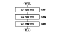
- FIG. 3 is a flowchart for explaining the manufacturing method 1 in the second embodiment of the present invention.
- FIG. 4 is a flow chart for explaining a manufacturing method 2 in the second embodiment of the present invention.
- FIG. 5 is a flow chart for explaining a manufacturing method 3 in the second embodiment of the present invention.
- FIG. 6 is a flowchart for explaining the manufacturing method 4 in the second embodiment of the present invention.
- FIG. 1 is a configuration diagram showing a configuration of a battery according to Embodiment 1 of the present invention.
- FIG. 2A is a configuration diagram showing a configuration of a battery according to Embodiment 2 of the present invention
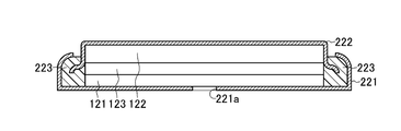
- FIG. 7A is a cross-sectional view showing a more detailed configuration example of a coin cell type battery according to a second embodiment of the present invention.
- FIG. 7B is a plan view showing a configuration example of a coin cell type battery according to Embodiment 2 of the present invention.
- FIG. 8 is a configuration diagram showing a configuration of another battery in the second embodiment of the present invention.
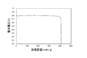
- FIG. 9 is a characteristic diagram showing a first-time discharge curve of an air battery using magnesium as the negative electrode in Experimental Example 1 of Embodiment 2 of the present invention.
- FIG. 10 is a characteristic diagram showing a first-time discharge curve of an air cell in which zinc is used as the negative electrode in Experimental Example 1 of Embodiment 2 of the present invention.
- FIG. 11 is a configuration diagram showing a configuration of a battery in the third embodiment of the present invention.
- FIG. 12 is a flow chart for explaining the manufacturing method 1 in the third embodiment of the present invention.
- FIG. 13 is a flow chart for explaining a manufacturing method 2 in the third embodiment of the present invention.
- FIG. 14 is a flow chart for explaining a manufacturing method 3 in the third embodiment of the present invention.
- FIG. 15 is a flow chart for illustrating a manufacturing method 4 in the third embodiment of the present invention.
- FIG. 16A is a cross-sectional view showing a more detailed configuration example of the coin cell type battery in the third embodiment of the present invention.
- FIG. 16B is a plan view showing a configuration example of a coin cell type battery according to Embodiment 2 of the present invention.
- FIG. 17 is a configuration diagram showing a configuration of another battery in the third embodiment of the present invention.
- FIG. 18 is a characteristic diagram showing an initial discharge curve of the water battery in Experimental Example 1 of Embodiment
- the battery in the first embodiment of the present invention will be described with reference to FIG.
- the battery in Embodiment 1 includes positive electrode 101, negative electrode 102, and electrolyte 103.
- the positive electrode 101 is composed of a co-continuum of a three-dimensional network structure composed of a plurality of nanostructures.
- the electrolyte 103 is disposed between the positive electrode 101 and the negative electrode 102, and is made of a salt.
- the electrolyte 103 may be composed of an aqueous solution of either potassium chloride and sodium chloride or a mixture thereof. Disposal is easy because the electrolyte 103 is made of salt. Also, there is no concern about the impact on the surrounding environment, and handling is easy.
- a plurality of nanostructures are integrated by non-covalent bonding to form a three-dimensional network structure, which is a co-continuum.
- the co-continuous body is a porous body and has an integral structure.
- the nanostructures are nanosheets or nanofibers.
- a co-continuum of a three-dimensional network structure in which a plurality of nanostructures are integrated by non-covalent bonding has a stretchable structure in which the bonding portion between the nanostructures is made deformable. .
- each of the plurality of nanostructures is a nanosheet composed of at least one of carbon, iron oxide, manganese oxide, zinc oxide, molybdenum oxide, and molybdenum sulfide.
- the sulfurized molybdenum compound is, for example, molybdenum disulfide, phosphorus-doped molybdenum sulfide or the like.
- the elements of these materials are 16 essential elements essential for plant growth (C, O, H, N, P, K, S, Ca, Mg, Fe, Mn, B, Zn, Cu, Mo, Cl It should just consist of).
- the elements of these materials may also be composed of Na, Si, Se, Co, Al, V, which are useful for plant growth.
- the nanosheets have conductivity.
- the nanosheet is defined as a sheet-like material having a thickness of 1 nm to 1 ⁇ m and a planar longitudinal length of 100 times or more of the thickness.
- the nanosheet may be in the form of a roll or a wave, the nanosheet may be curved or bent, and may have any shape.
- each of the plurality of nanostructures is a nanofiber composed of at least one of carbon, iron oxide, manganese oxide, zinc oxide, molybdenum oxide, molybdenum sulfide, and cellulose (carbonized cellulose).
- the elements of these materials are 16 essential elements essential for plant growth (C, O, H, N, P, K, S, Ca, Mg, Fe, Mn, B, Zn, Cu, Mo, Cl) It should just consist of.
- the elements of these materials may also be composed of Na, Si, Se, Co, Al, V, which are useful for plant growth.
- Nanofibers are defined as fibrous materials having a diameter of 1 nm to 1 ⁇ m and a length of 100 times or more of the diameter.
- the nanofibers may be hollow or coiled, and may have any shape.
- a sol or gel in which nanostructures are dispersed is frozen to form a frozen body (freezing step), and the frozen body is dried in vacuum (drying step) to produce a co-continuum serving as the positive electrode 101 can do.
- a gel in which nanofibers of iron oxide, manganese oxide, silicon, or cellulose are dispersed it can be produced by predetermined bacteria (gel production process).
- a gel is produced in which nanofibers of cellulose are dispersed in predetermined bacteria (gel production process), and the gel is carbonized by heating in an inert gas atmosphere to obtain a co-continuum (carbonization process) You may do so.
- the co-continuum constituting the positive electrode 101 preferably has, for example, an average pore diameter of 0.1 to 50 ⁇ m, and more preferably 0.1 to 2 ⁇ m.
- the average pore size is a value determined by mercury porosimetry.
- the positive electrode 101 does not need to use an additional material such as a binder as in the case of using a carbon powder, which is cost-effective and environmentally-friendly.
- the battery is, for example, an air battery using the positive electrode 101 as an air electrode.
- the battery is, for example, a water battery in which the active material in the positive electrode 101 is water.
- the negative electrode 102 may contain, for example, any metal of magnesium, zinc, iron, and aluminum.
- the positive electrode 101 may support a catalyst.
- the catalyst may be composed of an oxide of at least one metal of iron, manganese, zinc, copper, molybdenum, or at least one metal of calcium, iron, manganese, zinc, copper, molybdenum.
- the positive electrode is composed of a co-continuum of a three-dimensional network structure composed of a plurality of nanostructures, and the electrolyte is composed of a salt. It is easy. Moreover, according to the battery in the first embodiment, there is no concern about the influence on the surrounding environment, and the handling is easy.
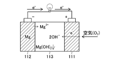
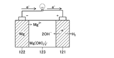
- the battery in the second embodiment is an air battery including a gas diffusion type air electrode (positive electrode) 111, a negative electrode 112, and an electrolyte 113.
- the air electrode 111 is composed of a co-continuum of a three-dimensional network structure composed of a plurality of nanostructures.
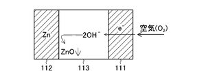
- the negative electrode 112 is configured to contain zinc or magnesium.
- the negative electrode 112 may include iron (Fe) or aluminum (Al).
- the electrolyte 113 is disposed between the air electrode 111 and the negative electrode 112 and is made of a salt.
- the electrolyte 113 may be composed of an aqueous solution of either potassium chloride and sodium chloride or a mixture thereof. Disposal is easy because the electrolyte 113 is made of salt. Also, there is no concern about the impact on the surrounding environment, and handling is easy. ,
- the electrolyte 113 may be either an electrolytic solution or a solid electrolyte.
- the electrolytic solution refers to the case where the electrolyte is in a liquid form.
- a solid electrolyte means the case where an electrolyte is a gel form or a solid form.
- the co-continuum described above is, for example, a three-dimensional network structure in which a plurality of nanostructures are integrated by non-covalent bonding.
- the co-continuous body is a porous body and has an integral structure.
- the nanostructures are nanosheets or nanofibers.
- a co-continuum of a three-dimensional network structure in which a plurality of nanostructures are integrated by non-covalent bonding has a stretchable structure in which the bonding portion between the nanostructures is made deformable. .
- each of the plurality of nanostructures is a nanosheet composed of at least one of carbon, iron oxide, manganese oxide, zinc oxide, molybdenum oxide, and molybdenum sulfide.
- the sulfurized molybdenum compound is, for example, molybdenum disulfide, phosphorus-doped molybdenum sulfide or the like.
- the elements of these materials are 16 essential elements essential for plant growth (C, O, H, N, P, K, S, Ca, Mg, Fe, Mn, B, Zn, Cu, Mo, Cl It should just consist of).
- the elements of these materials may also be composed of Na, Si, Se, Co, Al, V, which are useful for plant growth.
- the nanosheets have conductivity.
- the nanosheet is defined as a sheet-like material having a thickness of 1 nm to 1 ⁇ m and a planar longitudinal length of 100 times or more of the thickness.
- the nanosheet may be in the form of a roll or a wave, the nanosheet may be curved or bent, and may have any shape.
- each of the plurality of nanostructures is a nanofiber composed of at least one of carbon, iron oxide, manganese oxide, zinc oxide, molybdenum oxide, molybdenum sulfide, and cellulose (carbonized cellulose).
- the elements of these materials are 16 essential elements essential for plant growth (C, O, H, N, P, K, S, Ca, Mg, Fe, Mn, B, Zn, Cu, Mo, Cl) It should just consist of.
- the elements of these materials may also be composed of Na, Si, Se, Co, Al, V, which are useful for plant growth.
- Nanofibers are defined as fibrous materials having a diameter of 1 nm to 1 ⁇ m and a length of 100 times or more of the diameter.
- the nanofibers may be hollow or coiled, and may have any shape.
- a sol or gel in which nanostructures are dispersed is frozen to form a frozen body (freezing step), and the frozen body is dried in a vacuum (drying step) to form a co-continuum serving as the air electrode 111 It can be made. If it is a gel in which nanofibers of iron oxide, manganese oxide, silicon, or cellulose are dispersed, it can be produced by predetermined bacteria (gel production process).
- a gel is produced in which nanofibers of cellulose are dispersed in predetermined bacteria (gel production process), and the gel is carbonized by heating in an inert gas atmosphere to obtain a co-continuum (carbonization process) You may do so.
- the co-continuum constituting the air electrode 111 preferably has, for example, an average pore diameter of 0.1 to 50 ⁇ m, and more preferably 0.1 to 2 ⁇ m.
- the average pore size is a value determined by mercury porosimetry.
- the air electrode 111 does not need to use an additional material such as a binder as in the case of using a carbon powder, which is cost-effective and environmentally-friendly.
- the air electrode reaction is a reaction shown by “1 / 2O 2 + H 2 O + 2e ⁇ ⁇ 2OH ⁇ (1)” by contact of oxygen in the air and the electrolyte on the surface of the air electrode 111 having conductivity. proceed.
- the reaction of “Mg ⁇ Mg 2+ +2 e ⁇ (2)” proceeds in the negative electrode 112 in contact with the electrolyte 113, and the magnesium constituting the negative electrode 112 emits electrons. It dissolves in the electrolyte 113 as magnesium ions.
- the entire reaction is a reaction of “Mg + 1/2 O 2 + H 2 O + 2 e ⁇ ⁇ Mg (OH) 2 ... (3)” to form (precipitate) magnesium hydroxide.
- the theoretical electromotive force is about 2.7V.
- the compounds involved in the above reaction are shown along with the components in FIG. 2A.
- the air electrode 111 which is a positive electrode, can be manufactured by a known process of forming a carbon powder with a binder, but as described above, in the air battery, it is important to generate a large amount of reaction sites inside the air electrode 111.
- the air electrode 111 has a high specific surface area.
- the specific surface area of the co-continuum constituting the air electrode 111 is preferably 200 m 2 / g or more, and more preferably 300 m 2 / g or more.
- the conventional problems described above can be solved.
- the discharge capacity can be increased.
- the air electrode 111 may support a catalyst.
- the catalyst may be composed of at least one metal of iron, manganese, zinc, copper and molybdenum, or a metal oxide composed of at least one metal of calcium, iron, manganese, zinc, copper and molybdenum.
- the element of these materials is comprised from the metal contained in 16 types of essential elements essential to the growth of a plant, and it should just have catalytic ability.
- the elements of these materials may also be composed of Na, Si, Se, Co, Al, V, which are useful for plant growth.
- the metal is preferably iron, manganese or zinc, and an oxide of one of them or a composite oxide of two or more is preferable.
- manganese oxide (MnO 2 ) is preferable. Manganese oxide is preferred because it exhibits particularly excellent catalytic performance in the present invention.
- the metal oxide used as a catalyst is a hydrate-like amorphous thing.
- it may be a hydrate of the transition metal oxide described above. More specifically, it may be manganese (IV) oxide-n-hydrate.
- n is the number of moles of H 2 O relative to 1 mol of MnO 2 . It is possible to achieve excellent battery performance by supporting the hydrate of manganese oxide in the form of nano-sized fine particles with high dispersion on the surface of the co-continuum that constitutes the air electrode 111.
- the air electrode 111 For example, using, as the air electrode 111, highly dispersed (added) manganese oxide hydrate (MnO 2 ⁇ n H 2 O) as nano-sized fine particles on the co-continuum of the air electrode 111 Thus, it is possible to show excellent battery performance.
- the content of the catalyst contained in the air electrode 111 is 0.1 to 70% by weight, preferably 1 to 30% by weight, based on the total weight of the air electrode 111.
- the electrolyte solution of the electrolyte 113 penetrates into the air electrode 111, and at the same time, oxygen gas in the air is supplied to form a three-phase interface of electrolyte solution-electrode-gas (oxygen) as described above. If the catalyst has high activity at this three-phase interface site, oxygen reduction (discharge) on the electrode surface proceeds smoothly, and battery performance is greatly improved.
- Such a catalyst has a strong interaction with oxygen which is a positive electrode active material, so that it can adsorb many oxygen species on its surface or store oxygen species in oxygen vacancies.
- the oxygen species adsorbed on the metal oxide surface constituting the catalyst or occluded in the oxygen vacancy is a source of oxygen (active intermediate reactant) of the above formula (1) or formula (4) ) Is used for the oxygen reduction reaction, so that the above reaction proceeds easily.
- metal oxides such as manganese oxide effectively function as catalysts.
- metals themselves can be used as catalysts, and metals function in the same manner as the metal oxides.
- the catalyst in order to increase the efficiency of the battery, it is desirable that more reaction sites causing the electrode reaction [the above-mentioned electrolyte solution / electrode / air (oxygen) three-phase portion] be present. From such a point of view, it is important that the above-mentioned three-phase sites are also present in large amounts on the surface of the catalyst, and the catalyst preferably has a high specific surface area.
- the specific surface area of the metal or metal oxide catalyst may be 0.1 to 1000 m 2 / g, preferably 1 to 500 m 2 / g.
- the specific surface area is the specific surface area determined by the BET method by known N 2 adsorption.
- the air electrode 111 to which the catalyst is added can be manufactured by the method for manufacturing a positive electrode described later.
- the negative electrode 112 is composed of a negative electrode active material.
- the negative electrode active material is not particularly limited as long as it is a material that can be used as a negative electrode material of an air battery, that is, a material containing metallic magnesium, a magnesium-containing material, metallic zinc, and a zinc-containing material.
- the negative electrode 112 may be a sheet of metal magnesium, a sheet of metal magnesium, or a sheet of magnesium powder crimped to a metal foil such as copper. Further, for example, the negative electrode 112 may be formed of a sheet of metal zinc, metal zinc, or a sheet obtained by pressure-bonding zinc powder to a metal foil such as copper.
- the negative electrode 112 can be formed by a known method.
- the negative electrode 112 in the case where magnesium metal is used as the negative electrode 112, the negative electrode 112 can also be manufactured by stacking a plurality of metal magnesium foils and forming the same into a predetermined shape.
- the negative electrode 112 may be manufactured by molding a zinc plate into a predetermined shape. Note that the negative electrode 112 can also be manufactured by stacking a plurality of metal zinc foils and forming the same into a predetermined shape.
- the electrolyte 113 may be any substance that can move metal ions and hydroxide ions that make up the negative electrode 112 between the air electrode 111 (positive electrode) and the negative electrode 112.
- metal salts containing potassium and sodium abundantly present on the earth can be mentioned.
- This metal salt is one of 16 essential elements essential for plant growth (C, O, H, N, P, K, S, Ca, Mg, Fe, Mn, B, Zn, Cu, Mo, Cl ) And elements contained in seawater and rainwater. Moreover, it may be comprised from Na, Si, Se, Co, Al, V useful for the growth of a plant.
- the electrolyte 113 may be made of sodium chloride or potassium chloride as described above. Since potassium is one of the major components among the fertilizer components, potassium chloride is particularly preferable because it functions as a fertilizer as well as not only affecting the electrolyte leakage into the soil.
- the aromatic anion exchange polymer solid electrolyte which has the ion conductivity which lets zinc ion and hydroxide ion pass, and an inorganic layered compound type
- the air battery can include a separator, a battery case, a structural member such as a metal mesh (for example, copper mesh), and elements required for the air battery.
- a separator is not particularly limited as long as it is a fiber material, but a cellulose-based separator made of plant fibers or bacteria is particularly preferable.
- the air electrode 111, the negative electrode 112, and the electrolyte 113 obtained by the method of manufacturing a positive electrode described later, together with other necessary elements based on the desired air battery structure, in a suitable container such as a case. It can be produced by arranging appropriately.
- the manufacturing procedure of these air cells can apply conventionally known methods.
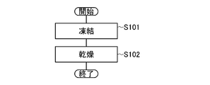
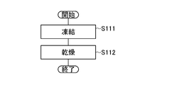
- step S101 a sol or gel in which nanostructures such as nanosheets and nanofibers are dispersed is frozen to obtain a frozen body (freeze step).
- step S102 the obtained frozen body is dried in vacuum to obtain a co-continuum (drying step).
- the freezing step of step S101 uses a nanostructure serving as a raw material of a stretchable co-continuum formed into a three-dimensional network structure composed of a plurality of nanostructures integrated together by non-covalent bonding. Maintenance or construction.
- gel means that the dispersion medium loses fluidity and becomes solid due to the three-dimensional network structure of the nanostructure which is a dispersoid. Specifically, it means a dispersion having a shear modulus of 10 2 to 10 6 Pa.
- the dispersion medium of the gel may be an aqueous system such as water (H 2 O) or a carboxylic acid, methanol (CH 3 OH), ethanol (C 2 H 5 OH), propanol (C 3 H 7 OH), n-butanol, iso Organic systems such as butanol, n-butylamine, dodecane, unsaturated fatty acid, ethylene glycol, heptane, hexadecane, isoamyl alcohol, octanol, isopropanol, acetone, glycerin and the like, and two or more of these may be mixed.
- aqueous system such as water (H 2 O) or a carboxylic acid, methanol (CH 3 OH), ethanol (C 2 H 5 OH), propanol (C 3 H 7 OH), n-butanol, iso
- Organic systems such as butanol, n-butylamine, dodecane,
- a sol means a colloid composed of a dispersion medium and a nanostructure which is a dispersoid. Specifically, it means a dispersion system having a shear modulus of 1 Pa or less.
- the dispersion medium of the sol may be an aqueous system such as water, carboxylic acid, methanol, ethanol, propanol, n-butanol, isobutanol, n-butylamine, dodecane, unsaturated fatty acid, ethylene glycol, heptane, hexadecane, isoamyl alcohol, octanol, It is an organic system such as isopropanol, acetone, glycerin and the like, and two or more of them may be mixed.
- the sol or gel in which the nanostructures are dispersed is housed in a suitable container such as a test tube, and is stored in the test tube by cooling the periphery of the test tube in a coolant such as liquid nitrogen It is carried out by freezing the sol or gel.
- a suitable container such as a test tube
- a coolant such as liquid nitrogen It is carried out by freezing the sol or gel.
- the method of freezing is not particularly limited as long as the dispersion medium of gel or sol can be cooled to the freezing point or lower, and may be cooled by a freezer or the like.
- the dispersion medium loses its fluidity and the dispersoid is fixed, whereby a three-dimensional network structure is constructed.
- the specific surface area can be freely adjusted by adjusting the concentration of the gel or sol, and the thinner the concentration of the gel or sol, the higher the specific surface area of the obtained co-continuum.
- the concentration of the dispersoid is preferably 0.01 to 10 wt% or less.
- the pores play a cushioning role during compression or tension and have excellent stretchability.
- the co-continuum preferably has a strain at the elastic limit of 5% or more, and more preferably 10% or more.
- the dispersoid If the dispersoid is not fixed by freezing, in the subsequent drying step, the dispersoid coagulates with evaporation of the dispersion medium, so a sufficiently high specific surface area can not be obtained, and co-continuous having a three-dimensional network structure The preparation of the body becomes difficult.
- the drying step is a step of taking out from the dispersion medium the dispersoid (a plurality of integrated fine structures) in which the three-dimensional network structure is maintained or constructed from the frozen body obtained in the freezing step.
- the frozen body obtained in the freezing step is dried in vacuum, and the frozen dispersion medium is sublimed from the solid state.
- the obtained frozen body is stored in a suitable container such as a flask, and the inside of the container is evacuated.
- the sublimation point of the dispersion medium is lowered, and it is possible to sublimate even a substance that does not sublime at normal pressure.
- the degree of vacuum in the drying step varies depending on the dispersion medium to be used, but is not particularly limited as long as the dispersion medium is a degree of vacuum which is sublimed.
- the degree of vacuum is preferably 1.0 ⁇ 10 ⁇ 6 to 1.0 ⁇ 10 ⁇ 2 Pa.
- heat may be applied using a heater or the like at the time of drying.
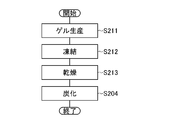
- step S201 a predetermined bacteria is caused to produce a gel in which nanofibers of any of iron oxide, manganese oxide, or cellulose are dispersed (gel production step).
- the gel thus obtained is used to make a co-continuum.
- the gel produced by bacteria has a basic structure of a fiber in the nm order, and by using this gel to produce a co-continuum, the resulting co-continuum has a high specific surface area.
- a gel produced by bacteria since it is desirable that the air electrode of the air battery have a high specific surface area, it is preferable to use a gel produced by bacteria. Specifically, synthesis of an air electrode (co-continuum) having a specific surface area of 300 m 2 / g or more is possible by using a gel produced by bacteria.
- the bacteria-produced gel has a structure in which the fibers are entangled in a coil or network, and further has a structure in which the nanofibers are branched based on the growth of bacteria. Achieves excellent stretchability with 50% or more of distortion. Therefore, a co-continuum prepared using a bacterial gel is suitable for the air electrode of an air battery.
- Two or more of bacterial cellulose, iron oxide and manganese oxide may be mixed as the bacterial gel.
- bacteria examples include known ones, for example, Acetobacter xylinum subspecies schlofermenta, Acetobacter xylinum ATCC 23768, Acetobacter xylinum ATCC 23769, Acetobacter pastilian ATCC 10245, Acetobacter xylinum ATCC 14851, acetobacter Acetobacter such as Bactor xylinum ATCC 11142, Acetobacter xylinum ATCC 10821, Agrobacterium genus, Rhizobium genus, Rhizobium genus, Sarcinia genus, Pseudomonas genus, Achromobacter genus, Alcaligenes genus, Aerobacter genus, Azotobacter genus, Switzerlandrea genus, Enterobacter group , Kleuvera, Leptothrix, Gallionella, Siderocapsa, Thiobacillus, and These may be those produced by culturing various mutant strains created by mutation
- the production method 1 As a method of obtaining a co-continuum using the gel produced by the above-mentioned bacteria, as in the production method 1, it is frozen at step S202 to form a frozen body (freeze step), and the frozen body is dried in vacuum at step S203. It may be made to be a co-continuous body (drying step). However, when using a gel in which nanofibers of cellulose produced by bacteria are dispersed, the produced co-continuum is carbonized by heating in a gas atmosphere in which cellulose does not burn in step S204 (carbonization step).
- Bacterial cellulose which is a component contained in bacteria-produced gel, does not have conductivity, so when used as an air electrode, carbonization imparts conductivity by heat treatment and carbonization in an inert gas atmosphere The process is important.
- the carbonized co-continuum has high conductivity, corrosion resistance, high stretchability, and high specific surface area, and is suitable as an air electrode of an air battery.
- carbonization of bacterial cellulose is carried out by synthesizing a co-continuum having a three-dimensional network structure consisting of bacterial cellulose by the freezing step and drying step described above, 500 ° C. to 2000 ° C. in an inert gas atmosphere, more preferably 900 It may be carbonized by firing at a temperature of 1 ° C. to 1800 ° C.
- inert gas such as nitrogen gas and argon gas
- it may be a reducing gas such as hydrogen gas or carbon monoxide gas, or may be carbon dioxide gas.
- carbon dioxide gas or carbon monoxide gas which has an activating effect on the carbon material and can be expected to be highly activated of the co-continuum, is more preferable.
- the catalyst may be supported on the air electrode.
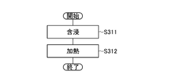
- step S301 the co-continuum obtained by the above-described production method 1 or production method 2 is impregnated with an aqueous solution of a metal salt to be a precursor of a catalyst (impregnation step).
- the stretchable co-continuum containing the metal salt may be heat-treated (heating step).
- the preferred metal of the metal salt used is at least one metal selected from the group consisting of iron, manganese, zinc, copper and molybdenum. In particular, manganese is preferred.
- a conventionally known method can be used to support the transition metal oxide on the co-continuum.
- a co-continuum is impregnated with an aqueous solution of transition metal chloride or transition metal nitrate, evaporated to dryness, and then hydrothermally synthesized in high-temperature and high-pressure water (H 2 O).
- H 2 O high-temperature and high-pressure water
- a precipitation method in which an aqueous solution of transition metal chloride or transition metal nitrate is impregnated into a co-continuum, and an alkaline aqueous solution is dropped here.
- a sol-gel method in which a co-continuum is impregnated with a transition metal alkoxide solution and then hydrolyzed.
- the conditions of each of these liquid phase methods are known, and these known conditions can be applied. In the present invention, the liquid phase method is desirable.
- the metal oxide supported by the above liquid phase method is in an amorphous state in many cases because crystallization has not progressed.
- a crystalline metal oxide can be obtained by heat treating the precursor in the amorphous state at a high temperature of about 500 ° C. in an inert atmosphere. Such crystalline metal oxides exhibit high performance even when used as a catalyst of the air electrode.
- the precursor powder obtained when the above amorphous precursor is dried at a relatively low temperature of about 100 to 200 ° C. becomes a hydrate while maintaining an amorphous state.
- Hydrates of metal oxides formally Me x O y n H 2 O (where Me means the above metals and x and y are the number of metals and oxygen contained in the metal oxide molecule, respectively) Where n can be expressed as the number of moles of H 2 O per mole of metal oxide). Hydrates of metal oxides obtained by such low temperature drying can be used as catalysts.
- Amorphous metal oxides (hydrates) have a large surface area and a particle diameter also shows a very small value of about 30 nm because sintering hardly progresses. This is suitable as a catalyst, and by using this, excellent battery performance can be obtained.
- crystalline metal oxides exhibit high activity, but metal oxides crystallized by heat treatment at high temperatures as described above may have a significantly reduced surface area, and particle diameter is caused by particle aggregation. Also, it may be about 100 nm.
- the particle diameter (average particle diameter) is a value obtained by measuring the diameter of particles per 10 ⁇ m square (10 ⁇ m ⁇ 10 ⁇ m) by magnifying observation with a scanning electron microscope (SEM) or the like to obtain an average value. .
- manufacturing method 4 manufacturing method 5, and manufacturing method 6 may be used.
- the catalyst is supported on the co-continuum produced by the production method 1 and the production method 2.
- the following catalyst loading step of loading a catalyst is added.
- the co-continuum is immersed in an aqueous solution of surfactant to adhere the surfactant to the surface of the co-continuum.
- the metal salt is adhered by the surfactant to the surface of the co-continuum to which the surfactant is adhered using an aqueous solution of the metal salt.
- the cocontinuum is loaded with a metal or metal oxide constituting the metal salt by heat treatment of the co-continuum to which the metal salt is attached.
- the metal is a metal oxide composed of at least one metal of iron, manganese, zinc, copper and molybdenum, or at least one metal of calcium, iron, manganese, zinc, copper and molybdenum.
- Mn or manganese oxide (MnO 2 ) is preferable.
- the surfactant used in the first catalyst supporting step of production method 4 is for supporting metal or transition metal oxide with high dispersion on the air electrode (co-continuum). If a hydrophobic group adsorbed on the carbon surface and a hydrophilic group adsorbed on the transition metal ion are adsorbed in the molecule like a surfactant, the metal particle which is a transition metal oxide precursor is highly dispersed in a co-continuum Can be adsorbed by
- the surfactant described above is not particularly limited as long as it has a hydrophobic group adsorbed on the carbon surface in the molecule and a hydrophilic group adsorbed on the manganese ion, but a nonionic surfactant is preferable.
- a nonionic surfactant for example, as an ester type surfactant, there are glycerin laurate, glycerin monostearate, sorbitan fatty acid ester, sucrose fatty acid ester and the like.
- an ether type surfactant there are polyoxyethylene alkyl ether, polyoxyethylene alkylphenyl ether, polyoxyethylene polyoxypropylene glycol and the like.
- ester ether type surfactants polyoxyethylene sorbitan fatty acid ester, polyoxyethylene hexitan fatty acid ester, sorbitan fatty acid ester polyethylene glycol and the like can be mentioned.
- alkanolamide type surfactants there are lauric acid diethanolamide, oleic acid diethanolamide, stearic acid diethanolamide, cocamide DEA and the like.
- a surfactant of higher alcohol there are cetanol, stearyl alcohol, oleyl alcohol and the like.
- a poloxamer type surfactant a poloxamer methacrylate etc. can be mentioned.
- the concentration of the aqueous solution of surfactant in the first catalyst supporting step of production method 4 is preferably 0.1 to 20 g / L.
- immersion conditions such as immersion time and immersion temperature include immersion in a solution at room temperature to 50 ° C. for 1 to 48 hours, for example.
- the second catalyst supporting step of the production method 4 further includes dissolving the metal salt functioning as a catalyst or adding an aqueous solution of the metal salt to the aqueous solution containing the surfactant in the first catalyst supporting step.
- an aqueous solution in which a metal salt functioning as a catalyst is dissolved is prepared, and the co-continuum impregnated (adhered) with the surfactant is immersed therein.
- the aqueous solution in which the metal salt is dissolved may be impregnated into the co-continuous body on which the surfactant is attached. If necessary, an alkaline aqueous solution may be dropped to the (contaminated) co-continuum containing the obtained metal salt. These allow metal or metal oxide precursors to be attached to the co-continuum.
- the addition amount of the metal salt in the second catalyst supporting step of production method 4 is preferably an amount of 0.1 to 100 mmol / L.
- immersion conditions such as immersion time and immersion temperature include immersion in a solution at room temperature to 50 ° C. for 1 to 48 hours, for example.
- a manganese metal salt for example, a manganese halide such as manganese chloride or a hydrate thereof
- a surfactant for example, a surfactant to form a co-continuous body.
- the supported amount of the catalyst by manganese oxide described above can be adjusted by the concentration of the metal salt (eg, manganese chloride) in the metal salt aqueous solution.
- the metal salt eg, manganese chloride
- the alkali used for the above-mentioned alkaline aqueous solution can mention the hydroxide of an alkali metal or alkaline-earth metal, ammonia water, ammonium aqueous solution, tetramethyl ammonium hydroxide (TMAH) aqueous solution, etc.
- the concentration of these alkaline aqueous solutions is preferably 0.1 to 10 mol / L.
- the precursor of the metal or metal oxide (metal salt) deposited on the surface of the co-continuum is converted to the metal itself or the metal oxide by heat treatment.
- the co-continuum to which the precursor is attached is dried at room temperature (about 25 ° C.) to 150 ° C., more preferably 50 ° C. to 100 ° C. for 1 to 24 hours, and then 100 to 600 ° C., preferably 110 Heat treatment may be performed at a temperature of 300 ° C.
- a heat treatment is performed in an inert atmosphere or reducing atmosphere such as argon, helium, nitrogen, etc. to produce an air electrode by a co-continuum in which the metal itself is adhered as a catalyst. be able to.
- a gas containing oxygen oxidative atmosphere
- heat treatment is performed under the above-mentioned reducing conditions, and once a co-continuum in which the metal itself is attached as a catalyst is prepared, and then heat treatment is performed in an oxidizing atmosphere to attach the metal oxide as a catalyst. It is also possible to manufacture an air electrode with a co-continuous structure.
- the metal or metal oxide precursor (metal salt) deposited co-continuum is dried at room temperature to 150 ° C., more preferably 50 ° C. to 100 ° C., and the metal itself is catalyzed on the co-continuum
- the metal / co-continuum complex may be made as attached.
- the adhesion amount (content) of the catalyst by metal or metal oxide is 0.1 to 70% by weight, preferably 1 to 30% by weight based on the total weight of the co-continuum and the catalyst .
- an air electrode in which a metal or metal oxide catalyst is highly dispersed can be manufactured on the surface of the co-continuum, and an air battery having excellent electric characteristics can be configured.
- manufacturing method 5 in the second embodiment will be described.
- the catalyst is supported on the co-continuum manufactured by the manufacturing method 1 and the manufacturing method 2 in a method different from the manufacturing method 4 described above.
- the following catalyst supporting step for supporting the catalyst is added.
- the co-continuum is immersed in an aqueous solution of a metal salt to deposit a metal salt on the surface of the co-continuum.
- the cocontinuum is made to support the catalyst composed of the metal constituting the metal salt by heat treatment of the co-continuum to which the metal salt is attached.
- the catalyst is converted to a metal oxide hydrate by causing the co-continuum supporting the catalyst to act on water at high temperature and pressure.
- the metal is a metal oxide composed of at least one metal of iron, manganese, zinc, copper and molybdenum, or at least one metal of calcium, iron, manganese, zinc, copper and molybdenum.
- Mn or manganese oxide (MnO 2 ) is preferable.
- an aqueous solution of a metal salt to be a precursor of a metal or a metal oxide to be finally used as a catalyst is attached (supported) on the surface of the co-continuous body.
- a aqueous solution in which the metal salt is dissolved may be separately prepared, and the aqueous solution may be impregnated into the co-continuous body.
- the conditions for impregnation, etc. are the same as in the prior art as described above.
- the second catalyst supporting step in the manufacturing method 5 is the same as the third catalyst supporting step in the manufacturing method 2, and heat treatment in an inert atmosphere or a reducing atmosphere may be performed. Further, the co-continuum to which the precursor is adhered, which has been described as another method of the third catalyst supporting step of production method 2, is heat treated (dried) at low temperature (room temperature to 150 ° C., more preferably 50 ° C. to 100 ° C.) Thus, the metal may be attached to the co-continuum.
- the air electrode 111 using a metal itself as a catalyst exhibits high activity, but since the catalyst is a metal, it is susceptible to corrosion and may lack long-term stability. On the other hand, long-term stability can be realized by heat-processing the metal into the hydrate of the metal oxide by the third catalyst supporting step of the manufacturing method 5 described in detail below.
- the hydrate of the metal oxide is attached to the co-continuous body.
- the metal-attached co-continuum obtained in the second catalyst supporting step of production method 5 is immersed in water at high temperature and pressure, and the metal attached is a metal oxide hydrate. Convert to a catalyst consisting of
- the metal-attached co-continuum is immersed in water at 100 ° C. to 250 ° C., more preferably 150 ° C. to 200 ° C. to oxidize the adhering metal to form a metal oxide hydrate. Just do it.
- the boiling point of water under atmospheric pressure (0.1 MPa) is 100 ° C., it can not normally be immersed in water at 100 ° C. or higher under atmospheric pressure, but a predetermined sealed container is used to By raising the pressure to, for example, 10 to 50 MPa, preferably about 25 MPa, the boiling point of water is raised in the closed container, and liquid water at 100 ° C. to 250 ° C. can be realized.
- the metal can be converted to a hydrate of metal oxide by immersing the co-continuum with metal attached in the high-temperature water thus obtained.
- manufacturing method 6 in the second embodiment will be described.
- the catalyst is supported on the co-continuum prepared by the manufacturing method 1 and the manufacturing method 2 in a method different from the manufacturing methods 4 and 5 described above.
- the following catalyst loading step of loading the catalyst is added.
- the co-continuum is immersed in an aqueous solution of a metal salt to deposit a metal salt on the surface of the co-continuum.
- the cocontinuum to which the metal salt is attached is caused to act on water at high temperature and high pressure to make the catalyst composed of the hydrate of the metal oxide by the metal constituting the metal salt a cocontinuum To carry.
- the metal may be at least one metal of iron, manganese, zinc, copper and molybdenum.
- the first catalyst supporting step in the manufacturing method 6 is the same as the first catalyst supporting step in the manufacturing method 5, and the description thereof is omitted here.
- the second catalyst supporting step in the production method 6 converts the precursor (metal salt) deposited on the surface of the co-continuum into a hydrate of metal oxide by heat treatment at a relatively low temperature.
- the co-continuum to which the precursor is attached is allowed to act on water at high temperature and pressure, and then dried at a relatively low temperature of about 100 to 200.degree.
- the precursor becomes a hydrate in which water molecules are present in the particles while maintaining the amorphous state of the precursor. Hydrates of metal oxides obtained by such low temperature drying are used as catalysts.
- the hydrate of the metal oxide can be supported with high dispersion in the form of nano-sized fine particles on the co-continuum. Therefore, when such a co-continuous body is used as an air electrode, it is possible to exhibit excellent battery performance.
- the co-continuum obtained by each of the above manufacturing methods can be formed into a predetermined shape by a known procedure to form an air electrode.
- the catalyst-unloaded and catalyst-loaded co-continuum is processed into a plate or sheet, and the obtained co-continuum is cut out into a circular shape of a desired diameter (for example 23 mm) with a punching blade, laser cutter or the like, do it.
- the battery using the air electrode 111, the negative electrode 112, and the electrolyte 113 in the above-described embodiment can be manufactured in a conventional shape such as a coin shape, a cylindrical shape, or a laminate shape.
- the manufacturing method of these batteries can use the method similar to the former.
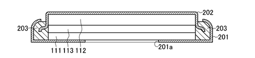
- the coin cell battery includes an air electrode 111 and a negative electrode 112, and an electrolyte 113 therebetween.
- the electrolyte 113 in this case is a sheet-like separator impregnated with an electrolytic solution.
- the air electrode case 201 is disposed on the air electrode 111 side, and the negative electrode case 202 is disposed on the negative electrode 112 side.
- the air electrode case 201 has an opening 201 a so that ambient air can contact the air electrode 111.
- the air electrode case 201 and the negative electrode case 202 are fitted, and a gasket 203 is disposed in the fitted portion.
- the electrolyte 113 is sandwiched between the air electrode 111 and the negative electrode 112 to form a battery cell, the battery cell is disposed between the air electrode case 201 and the negative electrode case 202, and the air electrode case 201 and the negative electrode case 202 are fitted together. Be one on one.
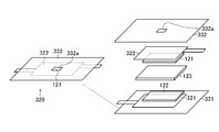
- the battery cell may be accommodated in the housing 300 by using a housing 300 that seals the inside of the battery cell other than the air electrode 111.
- the housing 300 is configured of a first housing 311 disposed on the side of the negative electrode 112 and a second housing 312 disposed on the side of the air electrode 111.
- An opening 321 a is formed in the second housing 312, and ambient air can be in contact with the air electrode 111.
- a negative electrode current collector 301 is provided between the first housing 311 and the negative electrode 112, and a positive electrode current collector 302 is provided between the second housing 312 and the air electrode 111.
- the terminal is taken out of the housing 300 from the outside. Note that when a metal is used as the negative electrode 112, the terminal may be taken out directly from the negative electrode 112 without using the negative electrode current collector 301.
- the electrolyte 113 may be composed of a sheet of a water-absorbing insulator such as a coffee filter, kitchen paper, or filter paper.
- a natural separator such as a cellulose separator made of plant fibers It is particularly preferred to use a sheet of material to be decomposed for the electrolyte 113.
- the housing 300 may be made of a material that can be maintained in the battery cell internally and is naturally decomposed.
- the housing 300 may be any of natural materials, microorganisms, and chemically synthesized materials, and is made of, for example, polylactic acid, polycaprolactone, polyhydroxyalkanoate, polyglycolic acid, modified polyvinyl alcohol, casein, modified starch, etc. can do. In particular, chemical synthesis systems such as plant-derived polylactic acid are preferred.
- the shape of the housing 300 is not limited as long as it is a shape obtained by processing biodegradable plastic.
- a sheet of paper coated with a resin such as polyethylene used for a milk pack or the like, an agar film or the like can be used.
- the air electrode 111, the negative electrode 112, the electrolyte 113, the first housing 311, the second housing 312, the negative electrode current collector 301, and the positive electrode current collector 302 do not impair their arrangement for operating as a battery.
- the shape is not limited. For example, in plan view, it can be used in a square or circular sheet shape or a rolled shape.
- the air battery according to the housing 300 made of the above-described naturally-degraded material spontaneously decomposes with time, and it is not necessary to recover the battery.
- the air battery according to the housing 300 made of the above-described naturally-degraded material spontaneously decomposes with time, and it is not necessary to recover the battery.
- Experimental Example 1 is an example in which a three-dimensional network structure co-continuum composed of a plurality of nanosheets integrated by non-covalent bonding is used as an air electrode.
- the cathode was synthesized as follows.
- a manufacturing method using graphene as a nanosheet is shown as a representative, a co-continuum having a three-dimensional network structure can be prepared by changing the graphene to a nanosheet of another material.
- the porosity shown below calculated and modeled the pore as a cylindrical shape from the pore diameter distribution which calculated
- graphene sol [dispersion medium: water (H 2 O), 0.4 wt%, silicon gma-Aldrich] is placed in a test tube, and the test tube is immersed in liquid nitrogen for 30 minutes to allow graphene sol Completely frozen. After completely freezing the graphene sol, the frozen graphene sol is taken out to an eggplant flask and dried in a vacuum of 10 Pa or less by a freeze dryer (manufactured by Tokyo Rika Kikai Co., Ltd.) to contain graphene nanosheets. An elastic co-continuum with three-dimensional network structure is obtained.
- the obtained co-continuum was evaluated by X-ray diffraction (XRD) measurement, scanning electron microscope (SEM) observation, porosity measurement, tensile test, and BET specific surface area measurement.
- the co-continuum prepared in the present invention was confirmed to be carbon (C, PDF card No. 01-075-0444) single phase from XRD measurement.
- the PDF card No. is a card number of a PDF (Powder Diffraction File) which is a database collected by the International Center for Diffraction Data (ICDD), and so forth.
- the obtained co-continuum is a co-continuum having an average pore diameter of 1 ⁇ m in which nanosheets (graphene pieces) are continuously connected. Moreover, it was 510 m ⁇ 2 > / g when BET specific surface area measurement of the co-continuum was measured by the mercury intrusion technique. Moreover, it was 90% or more when the porosity of the co-continuum was measured by the mercury intrusion method. Furthermore, from the results of the tensile test, it was confirmed that the obtained co-continuum did not exceed the elastic region and restored to the shape before the stress application even if the strain was applied by 20% by the tensile stress.
- Such a co-continuum of graphene was cut into a circle having a diameter of 14 mm by a punching blade, a laser cutter or the like to obtain a gas diffusion type air electrode.
- the negative electrode made of magnesium was prepared by cutting a commercially available metal magnesium plate (thickness 200 ⁇ m, manufactured by Niraco) into a circle having a diameter of 14 mm using a punching blade, a laser cutter or the like. Further, the negative electrode made of zinc was prepared by cutting a commercially available metallic zinc plate (thickness 200 ⁇ m, manufactured by Niraco) into a circle having a diameter of 14 mm using a punching blade, a laser cutter or the like.
- the electrolyte used was a solution in which potassium chloride (KCl, manufactured by Kanto Chemical Co., Ltd.) was dissolved in pure water at a concentration of 1 mol / L.
- KCl potassium chloride
- As a separator a cellulose-based separator (manufactured by Nippon High Paper Industry Co., Ltd.) for batteries was used.
- the coin cell type air battery described with reference to FIGS. 7A and 7B was manufactured using the above-described air electrode, negative electrode, electrolyte solution serving as an electrolyte, and a separator.
- the above-described air electrode was installed in an air electrode case in which the peripheral portion of a copper mesh foil (manufactured by MIT Japan) was fixed to the inside by spot welding.
- the negative electrode comprised from the metal magnesium board fixed the peripheral part to copper mesh foil (made by MIT Japan) by spot welding, and also spot-welded and fixed this copper mesh foil to the negative electrode case.
- the separator was placed on the air electrode installed in the air electrode case, and the electrolytic solution was injected into the placed separator.
- the negative electrode case to which the negative electrode was fixed was placed on the air electrode case, and the peripheral portions of the air electrode case and the negative electrode case were crimped with a coin cell caulking machine to produce a coin cell type air battery including a polypropylene gasket.
- the battery performance of the produced coin cell type air battery was measured. First, a discharge test was performed. The discharge test of the air battery uses a commercially available charge / discharge measurement system (SD8 charge / discharge system manufactured by Hokuto Denko Co., Ltd.), applies 0.1 mA / cm 2 current density per effective area of the air electrode, and opens circuit voltage The battery discharge test was performed until the battery voltage decreased to 0 V. The battery discharge test was performed in a thermostatic chamber at 25 ° C. (in the normal living environment). The discharge capacity was expressed as the value per unit weight (mAh / g) of the co-continuous air electrode.
- the discharge curve of the first time at the time of comprising negative electrode from magnesium in Experimental example 1 in Embodiment 2 is shown in FIG. Further, a first-time discharge curve in the case where the negative electrode is made of zinc in Experimental Example 1 in the second embodiment is shown in FIG.
- the average discharge voltage is 1.2 V and the discharge capacity is 1110 mAh / g when the negative electrode is made of magnesium and the co-continuum is used for the air electrode.
- the average discharge voltage is a battery voltage at a discharge capacity of 1 ⁇ 2 of the discharge capacity of the battery (1110 mAh / g in this experimental example) (555 mAh / g in Experimental Example 1).
- the average discharge voltage is 0.9 V and the discharge capacity is 500 mAh / g when the negative electrode is made of zinc and the co-continuum is used for the air electrode.
- the average discharge voltage is a battery voltage at a half discharge capacity (250 mAh / g in Experimental Example 1) of the discharge capacity of the battery (500 mAh / g in this Experimental Example).
- Fig. 7 shows a discharge capacity of an air battery in which a bicontinuous body is formed to form an air electrode and the negative electrode is formed of magnesium.
- FIG. 7 shows the discharge capacity of an air battery in which a co-continuum is formed from the nanosheets according to and used as an air electrode, and the negative electrode is formed of zinc.
- Experimental Example 2 is an example using a three-dimensional network structure co-continuum composed of a plurality of nanofibers integrated by non-covalent bonding as an air electrode.
- the cathode was synthesized as follows. In the following description, a manufacturing method using carbon nanofibers is shown as a representative, but by changing the carbon nanofibers to nanofibers made of other materials, a co-continuum having a three-dimensional network structure can be prepared .
- the evaluation method of the co-continuum, the preparation of the air cell, and the method of the discharge test were performed in the same manner as in Experimental Example 1 in the second embodiment.
- a co-continuum is produced in the same manner as the process shown in Experimental Example 1 in Embodiment 2, and the raw material is carbon nanofiber sol [dispersion medium: water (H 2 O), 0.4 wt%, Sigma-Aldrich Made] was used.
- the obtained co-continuum was evaluated by performing XRD measurement, SEM observation, porosity measurement, tensile test, and BET specific surface area measurement.
- the co-continuum prepared in the present invention was confirmed to be carbon (C, PDF card No. 00-058-1638) single phase from XRD measurement.
- C C, PDF card No. 00-058-1638
- the porosity of the co-continuous body was measured by the mercury intrusion method and found to be 93% or more.
- the co-continuum of Experimental example 2 in the embodiment 2 can be restored to the shape before the stress application without exceeding the elastic region even if the strain is applied by 40% by the tensile stress. confirmed.
- Tables 2-1, 2-2, 3-1, and 3-2 show discharge capacities of the air battery according to Experimental Example 2 of the second embodiment.
- Tables 2-1 and 3-1 show the results when the negative electrode is made of magnesium.
- Tables 2-2 and 3-2 show the results when the negative electrode is made of zinc.
- the discharge capacity in the case where the negative electrode is formed of magnesium shows 1160 mAh / g at the first time, and is higher than the case of using the graphene cocontinuum of Experimental Example 1 in Embodiment 2. It was a large value.
- the discharge capacity in the case where the negative electrode was made of zinc was 580 mAh / g at the first time, which was also a larger value than in the case of using the graphene cocontinuum of Experimental Example 1 in Embodiment 2. It is considered that such improvement of the characteristics is due to the smooth reaction at the time of discharge by using a more stretchable co-continuum.
- FIG. 2 shows the discharge capacity of an air battery in which a co-continuum is formed from nanofibers according to 2 ) to form an air electrode.
- the discharge capacity in any of Table 2-1 at the first time was 1000 mAh / g or more, which was an overall larger value than the co-continuum including the nanosheet as in Experimental Example 1 in the second embodiment. Also in the case of these nanofiber examples, it is considered that the discharge capacity is improved because the stretchable air electrode efficiently deposits the discharge product [Mg (OH) 2 ] as in the carbon nanofibers.
- the discharge capacity at the first time was 570 mAh / g or more, which was an overall larger value than the co-continuum including the nanosheet as in Experimental Example 1 in the second embodiment. . Also in the case of these nanofiber examples, it is considered that the discharge capacity is improved because the stretchable air electrode efficiently deposits the discharge product (ZnO) as in the carbon nanofibers.
- Experimental Example 3 Next, Experimental Example 3 in the second embodiment will be described.
- an air electrode formed by supporting an oxide or a metal as a catalyst on a co-continuum of carbon nanofibers will be described.
- MnO 2 is supported on a co-continuous as a catalyst
- any oxide can be supported on the co-continuous as a catalyst by changing Mn to an arbitrary metal.
- by not performing the neutralization step it is possible to load any metal as a catalyst on the co-continuum.
- the evaluation method of the co-continuum, the preparation of the air battery, and the charge / discharge test method were performed in the same manner as in Experimental Examples 1 and 2 in the second embodiment.
- the co-continuum was produced in the same manner as Experimental Example 2 in the second embodiment.
- commercially available manganese (II) tetrahydrate (RuCl 2 .4H 2 O; made by Kanto Chemical Co., Ltd.) was dissolved in distilled water, and the prepared co-continuum was impregnated to carry manganese chloride.
- ammonia water (28%) is gradually added dropwise to a co-continuum supporting manganese chloride (manganese chloride supported by the co-continuum) until the pH reaches 7.0 to precipitate ruthenium hydroxide by neutralization. I did. The precipitate was repeatedly washed five times with distilled water so that chlorine did not remain.
- the obtained manganese hydroxide-supporting co-continuum was heat-treated at 500 ° C. for 6 hours in an argon atmosphere to prepare a co-continuum supporting manganese oxide (MnO 2 ).
- the produced manganese oxide-supporting cocontinuum was evaluated by performing XRD measurement and TEM observation. From the XRD measurement, it was possible to observe a peak of manganese oxide (MnO 2 , PDF file No. 00-011-079).
- the catalyst supported on the co-continuous was confirmed to be a manganese oxide single phase. Further, it was observed by TEM that manganese oxide was precipitated in the form of particles having an average particle diameter of 100 nm on the surface of the co-continuous body.
- the coin cell type air battery similar to Experimental Examples 1 and 2 in Embodiment 2 was manufactured using the co-continuum supporting the manganese oxide as an air electrode.
- the discharge capacity of the air battery with a negative electrode of magnesium in Experimental Example 3 of Embodiment 2 produced was 1550 mAh / g.
- the discharge capacity of the air battery with a negative electrode of zinc in Experimental Example 3 in Embodiment 2 was 710 mAh / g.
- Tables 3-1 and 3-2 below also show the results when other catalysts are used.
- Experimental Example 4 describes a case where manganese oxide is further supported as a catalyst on a co-continuum of gel in which nanofibers produced by bacteria are dispersed.
- a co-continuum is prepared from iron oxide-produced nanofibers by iron bacteria is shown as a representative, but the iron oxide is changed to any bacteria to adjust the manganese oxide-bound nanofibers can do.
- the iron bacterium Leptothrix ochracea is placed in a JOP liquid medium in a test tube together with small pieces of iron (purity 99.9% or more, high purity chemical laboratory manufactured), and 20 shakers. C. for 14 days.
- JOP liquid medium 0.076 g of disodium hydrogen phosphate dodecahydrate, 0.02 g of potassium dihydrogen phosphate dihydrate in 1 L of sterile groundwater, HEPES [4- (2-hydroxyethyl) -1-piperazineethanesulfonic acid : Buffer material] 2.383 g, 0.01 mmol / L of iron sulfate, and the medium was adjusted to pH 7.0 with aqueous sodium hydroxide solution.
- Leptothrix ochracea was purchased from ATCC (American Type Culture Collection).
- the obtained co-continuum was evaluated by performing XRD measurement, SEM observation, porosity measurement, tensile test, and BET specific surface area measurement.
- the co-continuum prepared in the present invention is amorphous Fe 3 O 4 and ⁇ -Fe 2 O 3 (Fe 3 O 4 , PDF card No. 01-075-1372, ⁇ -Fe 2 O 3 , PDF by XRD measurement) It confirmed that it was card No. 00-039-1346).
- the discharge capacity of an air battery (anode is magnesium) in which an iron oxide-produced iron oxide nanofiber co-continuum of Experimental Example 4 in Embodiment 2 is used as the air electrode (the negative electrode is magnesium) was 1770 mAh / g.
- the discharge capacity of the air battery (the negative electrode is zinc) using the co-continuum of iron oxide-produced iron oxide nanofibers of Experimental Example 4 in Embodiment 2 for the air electrode was 720 mAh / g.
- Tables 4-1 and 4-2 below also show the results when other co-continuums are used.
- Table 4-1 shows the results of air batteries in which the negative electrode was made of magnesium.
- Table 4-2 shows the results of air batteries in which the negative electrode was made of zinc.
- the discharge capacity of the air battery (negative electrode is magnesium) by the air electrode catalyzed by manganese oxide was 1610 mAh / g at the first time using a co-continuum of bacteria-produced manganese oxide The value was larger than that of Experimental Example 3 in the second embodiment.
- the discharge capacity of the air battery (negative electrode is zinc) by the air electrode catalyzed by manganese oxide as a co-continuum of bacterial produced manganese oxide is 810 mAh / g at the first time The value was larger than that of Experimental Example 3 in the second embodiment.
- the bacterially produced manganese oxide was produced by culturing it in the same manner as described above using manganese small pieces (purity 99.9% or more, manufactured by High-Purity Chemical Laboratory) with the manganese bacterium Leptothrix discophora.
- Leptothrix discophora was purchased from ATCC.
- the discharge electrode is efficiently deposited by the air electrode having excellent elasticity produced by the bacteria, and hence the discharge capacity is considered to be improved. .
- Experimental Example 5 is a method of evaluating cocontinuum, method of producing air battery, and charge and discharge in a case where manganese oxide is further supported as a catalyst on a cocontinuum of gel in which cellulose produced in bacteria is dispersed. The test method was carried out in the same manner as Experimental Examples 1 and 2 in the second embodiment.
- the obtained co-continuum was evaluated by performing XRD measurement, SEM observation, porosity measurement, tensile test, and BET specific surface area measurement.
- This co-continuum was confirmed to be carbon (C, PDF card No. 01-071-4630) single phase by XRD measurement.
- the porosity of the co-continuum was measured by mercury porosimetry and was 99% or more.
- the results of the tensile test it is confirmed that even if strain is applied by 80% by tensile stress, it does not exceed the elastic region and restores to the shape before stress application, and has excellent stretchability even after carbonization.
- the discharge capacities of the air battery (negative electrode is magnesium) in Experimental Example 5 in Embodiment 2 are shown in Table 5-1 below.
- the discharge capacity of the air battery (negative electrode is zinc) in Experimental Example 5 in Embodiment 2 is shown in Table 5-2 below.
- Tables 5-1 and 5-2 also show the results of Experimental Examples 1, 2, 3 and 4 in the second embodiment.
- the discharge capacity shows 1950 mAh / g at the first time, and a co-continuum containing iron bacteria-produced iron oxide supporting manganese oxide as in Experimental Example 4 in Embodiment 2 is used. It was a larger value than it was.
- the discharge capacity shows 810 mAh / g at the first time, and iron bacteria-produced iron oxide supporting manganese oxide as in Experimental Example 4 in Embodiment 2.
- the value was larger than when using a co-continuum including.
- the above-mentioned characteristic improvement can be smoothly achieved by using the more stretchable co-continuum to deposit the discharge product efficiently at the time of discharge and because C has excellent conductivity. It is believed that a reaction has taken place.
- a stretchable co-continuum is obtained by high porosity and BET specific surface area measurement, and according to an air battery using this co-continuum as an air electrode, it is possible to discharge Efficient discharge product deposition is realized. It is considered that the improvement of the characteristics as described above is due to various improvements by the present invention.
- Experimental Example 6 is an air battery in which a case where the cellulose produced by bacteria is supported as a catalyst by dispersing manganese cellulose as a catalyst on the co-continuum of gel dispersed therein is also naturally decomposed as per the case described with reference to FIG. Was produced.
- the synthesis method of the co-continuum on which manganese oxide is supported as a catalyst, the evaluation method of the co-continuum, and the charge / discharge test method were performed in the same manner as in Experimental Example 5 in the second embodiment.
- the negative electrode is made of magnesium, it is manufactured by cutting a commercially available metal magnesium plate (thickness: 200 ⁇ m, manufactured by Niraco) into scissors of 20 mm ⁇ 20 mm square.
- the negative electrode was made of zinc by preparing a commercially available metallic zinc plate (200 ⁇ m thick, manufactured by Niraco) by cutting it into a 20 mm ⁇ 20 mm square using scissors.
- the electrolyte used was a solution in which potassium chloride (KCl, manufactured by Kanto Chemical Co., Ltd.) was dissolved in pure water at a concentration of 1 mol / L.
- the separator was used by cutting a cellulose-based separator (made by Nippon High Paper Industry Co., Ltd.) for batteries into a square of 25 mm ⁇ 25 mm.
- the negative electrode made of a metal magnesium plate is fixed to a copper mesh foil (manufactured by MIT Japan), which is a negative electrode current collector, by spot welding this peripheral portion, and further cut this copper mesh foil into 25 mm ⁇ 25 mm in plan view, This end was spot-welded to the short side of a copper foil (manufactured by Niraco) cut into 3 ⁇ 20 mm as a terminal.
- a copper mesh foil manufactured by MIT Japan
- the negative electrode made of a metallic zinc plate is fixed to a copper mesh foil (manufactured by MIT Japan), which is a negative electrode current collector, by spot welding this peripheral portion, and this copper mesh foil is further cut into 25 mm ⁇ 25 mm in plan view, This end was spot-welded to the short side of a copper foil (manufactured by Niraco) cut into 3 ⁇ 20 mm as a terminal.
- a copper mesh foil manufactured by MIT Japan
- the air electrode was crimped to a copper mesh foil (manufactured by MIT Japan) cut into 25 mm ⁇ 25 mm as a current collector for the air electrode, and the end cut of this copper mesh foil was cut into 3 ⁇ 20 mm as a terminal. Spot welding was performed on the short side of the foil (manufactured by Nirako).
- a plant-based film sheet Ecologe (manufactured by Mitsubishi Plastics Co., Ltd.) was used as a material of the casing. Two cut sheets were prepared by cutting this sheet into a plan view of 30 m ⁇ 30 mm, one of which was used as a first case and the other as a second case. In addition, an opening of 15 mm ⁇ 15 mm was formed in the central portion of the second housing used on the positive electrode side.
- a negative electrode current collector on which the negative electrode was fixed and a separator were disposed, and an electrolyte was further injected into the separator.
- the air electrode current collector to which the air electrode is crimped and the second housing are placed on this, and the first housing and the second inner peripheral portion (about 5 mm in width) are biodegradable resin (made by Miyoshi Yushi) Bonded and sealed. Thus, an air battery was produced.
- the discharge capacity of the air battery (negative electrode is magnesium) in Experimental Example 6 in Embodiment 2 is shown in Table 5-1. As shown in Table 5-1, in Experimental Example 6 in Embodiment 2, the discharge capacity exhibited 1880 mAh / g at the first time, and the discharge characteristics were substantially the same as those of Experimental Example 5 in Embodiment 2.
- the discharge capacity of the air battery (negative electrode is zinc) in Experimental Example 6 in Embodiment 2 is shown in Table 5-2. As shown in Table 5-2, in Experimental Example 6 in Embodiment 2, the discharge capacity shows 790 mAh / g at the first time, and the discharge characteristics are almost the same (95% or more) as in Experimental Example 5 in Embodiment 2. there were.
- Experimental Example 7 in the second embodiment will be described.
- a discharge test was performed on an air battery produced by the same procedure as Experimental Example 6 in Embodiment 2 in an environment simulating soil.
- the discharge capacity of the air battery (negative electrode is magnesium) in Experimental Example 7 in Embodiment 2 is shown in Table 5-1. As shown in Table 5-1, in the experimental example 7 in the second embodiment, the discharge capacity shows 1530 mAh / g at the first time, which is lower than the experimental example 6 in the second embodiment, but the problem also occurs in the soil environment. It was shown to work without.
- the discharge capacities of the air battery (negative electrode is zinc) in Experimental Example 7 in Embodiment 2 are shown in Table 5-2.
- the discharge capacity shows 690 mAh / g at the first time, which is lower than that of Experimental Example 6 in the second embodiment, but the problem is also in the soil environment. It was shown to work without. The cause of the decrease in volume is considered to be that the temperature in the soil is not stable.
- Comparative Example 1 Next, Comparative Example 1 will be described.
- the comparative example 1 produced and evaluated the air battery cell using carbon (Ketjen black EC600JD) and manganese oxide which are known as an electrode for air electrodes.
- carbon Ketjen black EC600JD
- manganese oxide which are known as an electrode for air electrodes.
- Comparative Example 1 a coin cell type air battery similar to that of Experimental Example 1 in Embodiment 2 was manufactured.
- Manganese oxide powder Kanto Chemical
- ketjen black powder Lion
- PTFE polytetrafluoroethylene
- the sheet electrode was cut into a circle having a diameter of 14 mm to obtain an air electrode.
- the conditions of the discharge test of the battery are the same as those of Experimental Example 1 in the second embodiment.
- the discharge capacities of the air battery (the negative electrode is magnesium) according to Comparative Example 1 are shown in Table 5-1 together with the results of Experimental Examples 1 to 7 in the second embodiment. As shown in Table 5-1, the initial discharge capacity of Comparative Example 1 was 750 mAh / g, which was smaller than that of Experimental Example 1 in Embodiment 2.
- the battery (air battery) in the second embodiment is superior in capacity and voltage to an air battery using an air electrode made of a known material.
- the air electrode is formed from the co-continuum formed into a three-dimensional network structure composed of a plurality of nanostructures integrated by non-covalent bonding, the air battery Can be handled more easily.
- the battery (aeroelectric) pond according to the second embodiment does not contain elements used for fertilizers in the soil or metal elements other than metals contained in rainwater or seawater and is naturally decomposed, so the environmental load is extremely low. .
- Such a battery can be effectively utilized as a disposable battery in a daily environment and various driving sources such as a sensor used in the soil. Further, according to the second embodiment, the discharge capacity of the battery can be increased.
- the battery according to the third embodiment is a water battery including a positive electrode 121, a negative electrode 122, and an electrolyte 123 which is disposed between the positive electrode 121 and the negative electrode 122 and is made of a salt.
- the negative electrode 122 contains, for example, magnesium, iron, aluminum or the like.
- the electrolyte 123 may be either an electrolytic solution or a solid electrolyte.
- the electrolytic solution refers to the case where the electrolyte is in a liquid form.
- a solid electrolyte means the case where an electrolyte is a gel form or a solid form.
- the positive electrode 121 is composed of a co-continuum in which a plurality of integrated nanostructures have a branch to form a three-dimensional network structure.
- the plurality of nanostructures are united by non-covalent bonding.
- the co-continuous body is a porous body and has an integral structure.
- the nanostructures are nanosheets or nanofibers.
- the nanosheet may be made of, for example, at least one of carbon, iron oxide, manganese oxide, magnesium oxide, molybdenum oxide, and a sulfurized molybdenum compound.
- the sulfurized molybdenum compound is, for example, molybdenum disulfide, phosphorus-doped molybdenum sulfide or the like.
- the elements of these materials are 16 essential elements essential for plant growth (C, O, H, N, P, K, S, Ca, Mg, Fe, Mn, B, Zn, Cu, Mo, Cl It should just consist of).
- the elements of these materials may also be composed of Na, Si, Se, Co, Al, V, which are useful for plant growth.
- the nanosheets have conductivity.
- the nanosheet is defined as a sheet-like material having a thickness of 1 nm to 1 ⁇ m and a planar longitudinal length of 100 times or more of the thickness.
- the nanosheet may be in the form of a roll or a wave, the nanosheet may be curved or bent, and may have any shape.
- the nanofibers may be made of at least one of carbon, iron oxide, manganese oxide, magnesium oxide, molybdenum oxide, molybdenum sulfide, and cellulose (carbonized cellulose).
- the elements of these materials are 16 essential elements essential for plant growth (C, O, H, N, P, K, S, Ca, Mg, Fe, Mn, B, Zn, Cu, Mo, Cl It should just consist of).
- the elements of these materials may also be composed of Na, Si, Se, Co, Al, V, which are useful for plant growth.
- Nanofibers are defined as fibrous materials having a diameter of 1 nm to 1 ⁇ m and a length of 100 times or more of the diameter.
- the nanofibers may be hollow or coiled, and may have any shape.
- a sol or gel in which nanostructures are dispersed is frozen to form a frozen body (freezing step), and the frozen body is dried in vacuum (drying step) to produce a co-continuum serving as the positive electrode 121 can do. If it is a gel in which nanofibers of iron oxide, manganese oxide, or cellulose are dispersed, it can be produced by predetermined bacteria (gel production process).
- a gel is produced in which nanofibers of cellulose are dispersed in predetermined bacteria (gel production process), and the gel is carbonized by heating in an inert gas atmosphere to obtain a co-continuum (carbonization process) You may do so.
- the co-continuum constituting the positive electrode 121 preferably has, for example, an average pore diameter of 0.1 to 50 ⁇ m, and more preferably 0.1 to 2 ⁇ m.
- the average pore size is a value determined by mercury porosimetry.
- the electrode reaction in the positive electrode 121 and the negative electrode 122 will be described.
- the reaction shown by “2H 2 O + 2e ⁇ ⁇ 2OH ⁇ + H 2 (6)” progresses when water (electrolyte 123) is in contact with the surface of the conductive positive electrode 121 having conductivity.
- the reaction of “Mg ⁇ Mg 2+ +2 e ⁇ (7)” proceeds in the negative electrode 122 in contact with the electrolyte 123, and magnesium constituting the negative electrode 122 Emits electrons and dissolves in the electrolyte 123 as magnesium ions.
- the positive electrode 121 which is a positive electrode, can be manufactured by a known process of forming carbon powder with a binder, but as described above, in the battery (water battery) in the third embodiment, a large amount of reaction sites are inside the positive electrode 121. It is important that the positive electrode 121 have a high specific surface area.
- the specific surface area of the co-continuum constituting the positive electrode 121 is preferably 200 m 2 / g or more, and more preferably 300 m 2 / g or more.
- the positive electrode 121 of the present invention in which the plurality of integrated nano-structures have a branch as described above and is configured by a co-continuous body having a three-dimensional network structure, the above-described conventional problems Can be eliminated, and the discharge capacity can be increased.
- the positive electrode 121 may support a catalyst.
- the catalyst may be composed of at least one metal of iron, manganese, zinc, copper and molybdenum, or a metal oxide composed of at least one metal of calcium, iron, manganese, zinc, copper and molybdenum.
- the element of these materials is comprised from the metal contained in 16 types of essential elements essential to the growth of a plant, and it should just have catalytic ability.
- the elements of these materials may also be composed of Na, Si, Se, Co, Al, V, which are useful for plant growth.
- the metal is preferably iron, manganese or zinc, and an oxide of one of them or a composite oxide of two or more is preferable.
- manganese oxide (MnO 2 ) is preferable. Manganese oxide is preferred because it exhibits particularly excellent catalytic performance in the present invention.
- the metal oxide used as a catalyst is a hydrate-like amorphous thing.
- it may be a hydrate of the transition metal oxide described above. More specifically, it may be manganese (IV) oxide-n-hydrate.
- n is the number of moles of H 2 O relative to 1 mol of MnO 2 . It is possible to achieve excellent battery performance by supporting the hydrate of manganese oxide in the form of nano-sized particles with high dispersion on the surface of the co-continuum constituting the positive electrode 121.
- the positive electrode 121 by using, as the positive electrode 121, highly dispersed (added) manganese oxide hydrate (MnO 2 ⁇ n H 2 O) as nano-sized fine particles on the co-continuum of the positive electrode 121 It is possible to show excellent battery performance.
- the content of the catalyst contained in the positive electrode 121 is 0.1 to 70% by weight, preferably 1 to 30% by weight, based on the total weight of the positive electrode 121.
- a transition metal oxide as a catalyst By adding a transition metal oxide as a catalyst to the positive electrode 121, the battery performance is greatly improved.
- the electrolyte solution of the electrolyte 123 penetrates into the positive electrode 121, and the above-described electrolyte-electrode interface is formed. At this interface site, if the catalyst is highly active, water reduction (discharge) on the electrode surface proceeds smoothly, and the battery performance is greatly improved.
- the catalyst in order to increase the efficiency of the battery, it is desirable that more reaction sites causing the electrode reaction [the above-mentioned electrolyte / electrode interface portion] be present. From such a viewpoint, it is important that the above-mentioned interface site is also present in a large amount on the surface of the catalyst, and the catalyst preferably has a high specific surface area.
- the specific surface area of the metal or metal oxide catalyst may be 0.1 to 1000 m 2 / g, preferably 1 to 500 m 2 / g.
- the specific surface area is the specific surface area determined by the BET method by known N 2 adsorption.
- the positive electrode 121 to which the catalyst is added can be manufactured by the method of manufacturing the positive electrode 121 described later.
- the negative electrode 122 is composed of a negative electrode active material.
- the negative electrode active material is not particularly limited as long as it is a material that can be used as a negative electrode material of a water battery, that is, it contains metallic magnesium, a magnesium-containing substance, metallic iron, an iron-containing substance, metallic aluminum, and an aluminum-containing substance.
- the negative electrode 122 may be made of metal magnesium, a sheet of metal magnesium, or a material obtained by pressure bonding a magnesium powder to a metal foil such as copper.
- the negative electrode 122 can be formed by a known method.
- the negative electrode 122 can also be manufactured by stacking a plurality of metal magnesium foils and forming the same into a predetermined shape.
- the electrolyte 123 may be any substance that can move ions of metal (for example, magnesium) constituting the negative electrode 122 and hydroxide ions between the positive electrode 121 and the negative electrode 122.
- metal salts containing potassium and sodium abundantly present on the earth can be mentioned.
- This metal salt is one of 16 essential elements essential for plant growth (C, O, H, N, P, K, S, Ca, Mg, Fe, Mn, B, Zn, Cu, Mo, Cl ) And elements contained in seawater and rainwater.
- the electrolyte 123 may be made of, for example, sodium chloride or potassium chloride. Since potassium is one of the major components among the fertilizer components, potassium chloride is particularly preferable because it functions as a fertilizer as well as not only affecting the electrolyte leakage into the soil.
- the aromatic anion exchange polymer solid electrolyte which has ion conductivity which allows magnesium ion and hydroxide ion to pass, and an inorganic layered compound type
- the water battery can include structural members such as a separator, a battery case, a metal foil (for example, copper foil), and elements required for a general air battery.
- structural members such as a separator, a battery case, a metal foil (for example, copper foil), and elements required for a general air battery.
- the separator is not particularly limited as long as it is a fiber material, but a cellulose-based separator made of plant fibers or bacteria is particularly preferable.
- the manufacturing method in the third embodiment will be described.
- the positive electrode 121, the negative electrode 122 and the electrolyte 123 obtained by the positive electrode manufacturing method described later, together with other necessary elements based on the desired structure of the water battery are housed in a suitable container such as a case. It can be produced by arranging it properly.
- the manufacturing procedure of these water cells can apply the method of the general air cell known conventionally.
- step S111 a sol or gel in which nanostructures such as nanosheets and nanofibers are dispersed is frozen to obtain a frozen body (freeze step).
- step S112 the obtained frozen body is dried in vacuum to obtain a co-continuum (drying step).
- a plurality of integrated nanostructures have branches, and the nanostructure is used as a raw material of a stretchable bicontinuous body formed into a three-dimensional network structure, and a three-dimensional network structure Maintenance or construction.
- gel means that the dispersion medium loses fluidity and becomes solid due to the three-dimensional network structure of the nanostructure which is a dispersoid. Specifically, it means a dispersion having a shear modulus of 10 2 to 10 6 Pa.
- the dispersion medium of the gel may be an aqueous system such as water (H 2 O) or a carboxylic acid, methanol (CH 3 OH), ethanol (C 2 H 5 OH), propanol (C 3 H 7 OH), n-butanol, iso Organic systems such as butanol, n-butylamine, dodecane, unsaturated fatty acid, ethylene glycol, heptane, hexadecane, isoamyl alcohol, octanol, isopropanol, acetone, glycerin and the like, and two or more of these may be mixed.
- aqueous system such as water (H 2 O) or a carboxylic acid, methanol (CH 3 OH), ethanol (C 2 H 5 OH), propanol (C 3 H 7 OH), n-butanol, iso
- Organic systems such as butanol, n-butylamine, dodecane,
- a sol means a colloid composed of a dispersion medium and a nanostructure which is a dispersoid. Specifically, it means a dispersion system having a shear modulus of 1 Pa or less.
- the dispersion medium of the sol may be an aqueous system such as water, carboxylic acid, methanol, ethanol, propanol, n-butanol, isobutanol, n-butylamine, dodecane, unsaturated fatty acid, ethylene glycol, heptane, hexadecane, isoamyl alcohol, octanol, It is an organic system such as isopropanol, acetone, glycerin and the like, and two or more of them may be mixed.
- the sol or gel in which the nanostructures are dispersed is housed in a suitable container such as a test tube, and is stored in the test tube by cooling the periphery of the test tube in a coolant such as liquid nitrogen It is carried out by freezing the sol or gel.
- a suitable container such as a test tube
- a coolant such as liquid nitrogen It is carried out by freezing the sol or gel.
- the method of freezing is not particularly limited as long as the dispersion medium of gel or sol can be cooled to the freezing point or lower, and may be cooled by a freezer or the like.
- the dispersion medium loses its fluidity and the dispersoid is fixed, whereby a three-dimensional network structure is constructed.
- the specific surface area can be freely adjusted by adjusting the concentration of the gel or sol, and the thinner the concentration of the gel or sol, the higher the specific surface area of the obtained co-continuum.
- the concentration of the dispersoid is preferably 0.01 to 10 wt% or less.
- the pores play a cushioning role during compression or tension and have excellent stretchability.
- the co-continuum preferably has a strain at the elastic limit of 5% or more, and more preferably 10% or more.
- the dispersoid If the dispersoid is not fixed by freezing, in the subsequent drying step, the dispersoid coagulates with evaporation of the dispersion medium, so a sufficiently high specific surface area can not be obtained, and co-continuous having a three-dimensional network structure The preparation of the body becomes difficult.
- the drying step is a step of taking out from the dispersion medium the dispersoid (a plurality of integrated fine structures) in which the three-dimensional network structure is maintained or constructed from the frozen body obtained in the freezing step.
- the frozen body obtained in the freezing step is dried in vacuum, and the frozen dispersion medium is sublimed from the solid state.
- the obtained frozen body is stored in a suitable container such as a flask, and the inside of the container is evacuated.
- the sublimation point of the dispersion medium is lowered, and it is possible to sublimate even a substance that does not sublime at normal pressure.
- the degree of vacuum in the drying step varies depending on the dispersion medium to be used, but is not particularly limited as long as the dispersion medium is a degree of vacuum which is sublimed.
- the degree of vacuum is preferably 1.0 ⁇ 10 ⁇ 6 to 1.0 ⁇ 10 ⁇ 2 Pa.
- heat may be applied using a heater or the like at the time of drying.
- step S211 a predetermined bacteria is caused to produce a gel in which nanofibers of any of iron oxide, manganese oxide, or cellulose are dispersed (gel production step).
- the gel thus obtained is used to make a co-continuum.
- the gel produced by bacteria has a basic structure of a fiber in the nm order, and by using this gel to produce a co-continuum, the resulting co-continuum has a high specific surface area.
- a gel produced by bacteria since it is desirable that the positive electrode of the water battery has a high specific surface area, it is preferable to use a gel produced by bacteria. Specifically, synthesis of a positive electrode (co-continuum) having a specific surface area of 300 m 2 / g or more is possible by using a gel produced by bacteria.
- the bacteria-produced gel has a structure in which the fibers are entangled in a coil or network, and further has a structure in which the nanofibers are branched based on the growth of bacteria. Achieves excellent stretchability with 50% or more of distortion. Therefore, a co-continuum prepared using a bacterial gel is suitable for the air electrode of a water battery.
- Two or more of bacterial cellulose, iron oxide and manganese oxide may be mixed as the bacterial gel.
- bacteria examples include known ones, for example, Acetobacter xylinum subspecies schlofermenta, Acetobacter xylinum ATCC 23768, Acetobacter xylinum ATCC 23769, Acetobacter pastilian ATCC 10245, Acetobacter xylinum ATCC 14851, acetobacter Acetobacter such as Bactor xylinum ATCC 11142, Acetobacter xylinum ATCC 10821, Agrobacterium genus, Rhizobium genus, Rhizobium genus, Sarcinia genus, Pseudomonas genus, Achromobacter genus, Alcaligenes genus, Aerobacter genus, Azotobacter genus, Switzerlandrea genus, Enterobacter group , Kleuvera, Leptothrix, Gallionella, Siderocapsa, Thiobacillus, and These may be those produced by culturing various mutant strains created by mutation
- step S212 As a method of obtaining a co-continuum using the gel produced by the above-mentioned bacteria, as in the production method 1 in the third embodiment, it is frozen in step S212 to form a frozen body (freeze step), and in step S213 The body may be dried in vacuum to form a co-continuum (drying step).
- drying step when using a gel in which nanofibers of cellulose produced by bacteria are dispersed, the produced co-continuum is carbonized by heating in a gas atmosphere in which cellulose does not burn in step S214 (carbonization step).
- Bacterial cellulose which is a component contained in bacteria-produced gel, does not have conductivity, so when used as an air electrode, carbonization imparts conductivity by heat treatment and carbonization in an inert gas atmosphere The process is important.
- the carbonized co-continuum has high conductivity, corrosion resistance, high stretchability, and high specific surface area, and is suitable as a positive electrode of a water battery.
- carbonization of bacterial cellulose is carried out by synthesizing a co-continuum having a three-dimensional network structure consisting of bacterial cellulose by the freezing step and drying step described above, 500 ° C. to 2000 ° C. in an inert gas atmosphere, more preferably 900 It may be carbonized by firing at a temperature of 1 ° C. to 1800 ° C.
- inert gas such as nitrogen gas and argon gas
- it may be a reducing gas such as hydrogen gas or carbon monoxide gas, or may be carbon dioxide gas.
- carbon dioxide gas or carbon monoxide gas which has an activating effect on the carbon material and can be expected to be highly activated of the co-continuum, is more preferable.
- the positive electrode may be loaded with a catalyst.
- step S311 the co-continuum obtained in Production method 1 or Production method 2 in Embodiment 3 described above is impregnated with an aqueous solution of a metal salt to be a precursor of a catalyst (impregnation step).
- the stretchable co-continuum containing the metal salt may be heat-treated (heating step).
- the preferred metal of the metal salt used is at least one metal selected from the group consisting of iron, manganese, zinc, copper and molybdenum. In particular, manganese is preferred.
- a conventionally known method can be used to support the transition metal oxide on the co-continuum.
- a co-continuum is impregnated with an aqueous solution of transition metal chloride or transition metal nitrate, evaporated to dryness, and then hydrothermally synthesized in high-temperature and high-pressure water (H 2 O).
- H 2 O high-temperature and high-pressure water
- a precipitation method in which an aqueous solution of transition metal chloride or transition metal nitrate is impregnated into a co-continuum, and an alkaline aqueous solution is dropped here.
- a sol-gel method in which a co-continuum is impregnated with a transition metal alkoxide solution and then hydrolyzed.
- the conditions of each of these liquid phase methods are known, and these known conditions can be applied. In the present invention, the liquid phase method is desirable.
- the metal oxide supported by the above liquid phase method is in an amorphous state in many cases because crystallization has not progressed.
- a crystalline metal oxide can be obtained by heat treating the precursor in the amorphous state at a high temperature of about 500 ° C. in an inert atmosphere. Such crystalline metal oxides exhibit high performance even when used as a catalyst for the positive electrode.
- the precursor powder obtained when the above amorphous precursor is dried at a relatively low temperature of about 100 to 200 ° C. becomes a hydrate while maintaining an amorphous state.
- Hydrates of metal oxides formally Me x O y n H 2 O (where Me means the above metals and x and y are the number of metals and oxygen contained in the metal oxide molecule, respectively) Where n can be expressed as the number of moles of H 2 O per mole of metal oxide). Hydrates of metal oxides obtained by such low temperature drying can be used as catalysts.
- Amorphous metal oxides (hydrates) have a large surface area and a particle diameter also shows a very small value of about 30 nm because sintering hardly progresses. This is suitable as a catalyst, and by using this, excellent battery performance can be obtained.
- crystalline metal oxides exhibit high activity, but metal oxides crystallized by heat treatment at high temperatures as described above may have a significantly reduced surface area, and particle diameter is caused by particle aggregation. Also, it may be about 100 nm.
- the particle diameter (average particle diameter) is a value obtained by measuring the diameter of particles per 10 ⁇ m square (10 ⁇ m ⁇ 10 ⁇ m) by magnifying observation with a scanning electron microscope (SEM) or the like to obtain an average value. .
- manufacturing method 4 manufacturing method 5, and manufacturing method 6 may be used.
- the catalyst is supported on the co-continuum manufactured by the manufacturing method 1 and the manufacturing method 2 in the third embodiment.
- the following catalyst supporting step of supporting a catalyst is added.
- the co-continuum is immersed in an aqueous solution of surfactant to attach the surfactant to the surface of the co-continuum.
- the metal salt is adhered by the surfactant to the surface of the co-continuum to which the surfactant is adhered using the aqueous solution of the metal salt.
- the cocontinuum is made to support the metal or the oxide of the metal oxide constituting the metal salt by heat treatment of the cocontinuum to which the metal salt is attached.
- the metal is a metal oxide composed of at least one metal of iron, manganese, zinc, copper and molybdenum, or at least one metal of calcium, iron, manganese, zinc, copper and molybdenum.
- Mn or manganese oxide (MnO 2 ) is preferable.
- the surfactant used in the first catalyst supporting step of production method 4 in the third embodiment is for supporting metal or transition metal oxide with high dispersion on the air electrode (co-continuum). If a hydrophobic group adsorbed on the carbon surface and a hydrophilic group adsorbed on the transition metal ion are adsorbed in the molecule like a surfactant, the metal particle which is a transition metal oxide precursor is highly dispersed in a co-continuum Can be adsorbed by
- the surfactant described above is not particularly limited as long as it has a hydrophobic group adsorbed on the carbon surface in the molecule and a hydrophilic group adsorbed on the manganese ion, but a nonionic surfactant is preferable.
- a nonionic surfactant for example, as an ester type surfactant, there are glycerin laurate, glycerin monostearate, sorbitan fatty acid ester, sucrose fatty acid ester and the like.
- an ether type surfactant there are polyoxyethylene alkyl ether, polyoxyethylene alkylphenyl ether, polyoxyethylene polyoxypropylene glycol and the like.
- ester ether type surfactants polyoxyethylene sorbitan fatty acid ester, polyoxyethylene hexitan fatty acid ester, sorbitan fatty acid ester polyethylene glycol and the like can be mentioned.
- alkanolamide type surfactants there are lauric acid diethanolamide, oleic acid diethanolamide, stearic acid diethanolamide, cocamide DEA and the like.
- a surfactant of higher alcohol there are cetanol, stearyl alcohol, oleyl alcohol and the like.
- a poloxamer type surfactant a poloxamer methacrylate etc. can be mentioned.
- the concentration of the aqueous solution of surfactant in the first catalyst supporting step of Production Method 4 in Embodiment 3 is preferably 0.1 to 20 g / L.
- immersion conditions such as immersion time and immersion temperature include immersion in a solution at room temperature to 50 ° C. for 1 to 48 hours, for example.
- the metal salt functioning as a catalyst is further dissolved in the aqueous solution containing the surfactant in the first catalyst supporting step, or an aqueous solution of metal salt is added.
- an aqueous solution of metal salt is added separately from the above-described aqueous solution containing a surfactant, an aqueous solution in which a metal salt functioning as a catalyst is dissolved is prepared, and the co-continuum impregnated (adhered) with the surfactant is immersed therein. May be
- the aqueous solution in which the metal salt is dissolved may be impregnated into the co-continuous body on which the surfactant is attached. If necessary, an alkaline aqueous solution may be dropped to the (contaminated) co-continuum containing the obtained metal salt. These allow metal or metal oxide precursors to be attached to the co-continuum.
- the addition amount of the metal salt in the second catalyst supporting step of Production Method 4 in Embodiment 3 is preferably an amount of 0.1 to 100 mmol / L.
- immersion conditions such as immersion time and immersion temperature include immersion in a solution at room temperature to 50 ° C. for 1 to 48 hours, for example.
- a manganese metal salt for example, a manganese halide such as manganese chloride or a hydrate thereof
- a surfactant for example, a surfactant to form a co-continuous body.
- the supported amount of the catalyst by manganese oxide described above can be adjusted by the concentration of the metal salt (eg, manganese chloride) in the metal salt aqueous solution.
- the metal salt eg, manganese chloride
- the alkali used for the above-mentioned alkaline aqueous solution can mention the hydroxide of an alkali metal or alkaline-earth metal, ammonia water, ammonium aqueous solution, tetramethyl ammonium hydroxide (TMAH) aqueous solution, etc.
- the concentration of these alkaline aqueous solutions is preferably 0.1 to 10 mol / L.
- the precursor (metal salt) of the metal or metal oxide deposited on the surface of the co-continuum is converted to the metal itself or the metal oxide by heat treatment.
- the co-continuum to which the precursor is attached is dried at room temperature (about 25 ° C.) to 150 ° C., more preferably 50 ° C. to 100 ° C. for 1 to 24 hours, and then 100 to 600 ° C., preferably 110 Heat treatment may be performed at a temperature of 300 ° C.
- heat treatment is performed in an inert atmosphere or reducing atmosphere such as argon, helium, nitrogen, etc., whereby the metal itself is attached to the surface as a catalyst.
- the positive electrode can be manufactured. Further, by heat treatment in a gas containing oxygen (oxidative atmosphere), it is possible to manufacture a positive electrode of a co-continuum in which a metal oxide is used as a catalyst to adhere to the surface.
- heat treatment is performed under the above-mentioned reducing conditions, and once a co-continuum in which the metal itself is attached as a catalyst is prepared, and then heat treatment is performed in an oxidizing atmosphere to attach the metal oxide as a catalyst. It is also possible to produce a positive electrode with a co-continuum.
- the metal or metal oxide precursor (metal salt) deposited co-continuum is dried at room temperature to 150 ° C., more preferably 50 ° C. to 100 ° C., and the metal itself is catalyzed on the co-continuum
- the metal / co-continuum complex may be made as attached.
- the deposition amount (content) of the metal or metal oxide catalyst is 0.1 to 70% by weight, preferably 1 to 70% by weight based on the total weight of the co-continuum and the catalyst. It is 30% by weight.
- the manufacturing method 4 in the third embodiment it is possible to manufacture a positive electrode in which a metal or metal oxide catalyst is highly dispersed on the surface of the co-continuum, and a water battery having excellent battery characteristics can be configured become.
- manufacturing method 5 in the third embodiment will be described.
- the co-continuum produced by the manufacturing method 1 and the manufacturing method 2 in the third embodiment is different from the manufacturing method 4 in the third embodiment described above in the method of catalyzing To carry.
- the following catalyst supporting step for supporting a catalyst is added.
- the co-continuum is immersed in an aqueous solution of a metal salt to deposit a metal salt on the surface of the co-continuum.
- the cocontinuum is made to support the catalyst composed of the metal constituting the metal salt by heat treatment of the co-continuum to which the metal salt is attached.
- the catalyst is converted to a metal oxide hydrate by causing the co-continuum supporting the catalyst to act on water at high temperature and pressure.
- the metal is a metal oxide composed of at least one metal of iron, manganese, zinc, copper and molybdenum, or at least one metal of calcium, iron, manganese, zinc, copper and molybdenum.
- Mn or manganese oxide (MnO 2 ) is preferable.
- an aqueous solution of a metal salt to be a precursor of a metal or metal oxide to be used as a catalyst is attached (supported) on the surface of the co-continuum.
- an aqueous solution in which the metal salt is dissolved may be separately prepared, and the aqueous solution may be impregnated into the co-continuous body.
- the conditions for impregnation, etc. are the same as in the prior art as described above.
- the second catalyst supporting step in the manufacturing method 5 in the third embodiment is the same as the third catalyst supporting step in the manufacturing method 4 in the third embodiment, and the heat treatment in an inert atmosphere or a reducing atmosphere may be performed.
- the co-continuum to which the precursor is attached which has been described as another method of the third catalyst supporting step of production method 4 in the third embodiment, is heated at low temperature (room temperature to 150 ° C., more preferably 50 ° C. to 100 ° C.)
- the metal may be deposited on the co-continuum by treatment (drying).
- the positive electrode 121 using a metal itself as a catalyst exhibits high activity, but since the catalyst is a metal, it is susceptible to corrosion and may lack long-term stability. On the other hand, long-term stability is realized by heat-treating the metal in the third catalyst supporting step of production method 5 in the third embodiment described in detail below to obtain a metal oxide hydrate. Can.
- the hydrate of the metal oxide is in a state of being attached to the co-continuous body.
- the co-continuum with metal attached obtained in the second catalyst supporting step of production method 5 in the third embodiment is immersed in water at high temperature and high pressure, and the metal attached is oxidized by metal oxidation. Convert to a catalyst consisting of the hydrate of
- the metal-attached co-continuum is immersed in water at 100 ° C. to 250 ° C., more preferably 150 ° C. to 200 ° C. to oxidize the adhering metal to form a metal oxide hydrate. Just do it.
- the boiling point of water under atmospheric pressure (0.1 MPa) is 100 ° C., it can not normally be immersed in water at 100 ° C. or higher under atmospheric pressure, but a predetermined sealed container is used to By raising the pressure to, for example, 10 to 50 MPa, preferably about 25 MPa, the boiling point of water is raised in the closed container, and liquid water at 100 ° C. to 250 ° C. can be realized.
- the metal can be converted to a hydrate of metal oxide by immersing the co-continuum with metal attached in the high-temperature water thus obtained.
- manufacturing method 6 in the third embodiment Next, manufacturing method 6 in the third embodiment will be described.
- Support the catalyst In the production method 6 in the third embodiment, in addition to the production of the co-continuum described above, the following catalyst supporting step of supporting a catalyst is added.
- the co-continuum is immersed in an aqueous solution of a metal salt to deposit a metal salt on the surface of the co-continuum.
- the cocontinuum to which the metal salt is attached is caused to act on water at high temperature and high pressure to make the catalyst composed of the hydrate of the metal oxide by the metal constituting the metal salt a cocontinuum To carry.
- the metal may be at least one metal of iron, manganese, zinc, copper and molybdenum.
- the first catalyst supporting step in the manufacturing method 6 in the third embodiment is the same as the first catalyst supporting step in the manufacturing method 5 in the third embodiment, and the description thereof is omitted here.
- the second catalyst supporting step in production method 6 in the third embodiment converts the precursor (metal salt) deposited on the surface of the co-continuum into a hydrate of metal oxide by heat treatment at a relatively low temperature. .
- the co-continuum to which the precursor is attached is allowed to act on water at high temperature and pressure, and then dried at a relatively low temperature of about 100 to 200.degree.
- the precursor becomes a hydrate in which water molecules are present in the particles while maintaining the amorphous state of the precursor. Hydrates of metal oxides obtained by such low temperature drying are used as catalysts.
- the hydrate of the metal oxide can be supported in a highly dispersed state in the form of nano-sized fine particles on the co-continuous body. Therefore, when such a co-continuum is used as a positive electrode, it becomes possible to show excellent battery performance.
- the co-continuum obtained by each of the above manufacturing methods can be formed into a predetermined shape by a known procedure to be used as a positive electrode.
- the catalyst-unloaded and catalyst-loaded co-continuum are processed into a plate or sheet, and the resulting co-continuum is cut into a circle of a desired diameter (for example, 23 mm) with a punching blade, laser cutter or the like to form a positive electrode. Just do it.
- the battery using the positive electrode 121, the negative electrode 122, and the electrolyte 123 in the embodiment described above can be manufactured in a conventional shape such as a coin shape, a cylindrical shape, or a laminate shape.
- the manufacturing method of these batteries can use the method similar to the former.
- the coin cell battery includes a positive electrode 121 and a negative electrode 122, and an electrolyte 123 therebetween.
- the electrolyte 123 in this case is a sheet-like separator impregnated with an electrolytic solution.
- the positive electrode case 221 is disposed on the side of the positive electrode 121, and the negative electrode case 222 is disposed on the side of the negative electrode 122.
- the positive electrode case 221 has an opening 221 a so that the gas generated at the positive electrode 121 can be released to the atmosphere.
- the positive electrode case 221 and the negative electrode case 222 are fitted, and a gasket 223 is disposed in the fitted portion.
- the electrolyte 123 is sandwiched between the positive electrode 121 and the negative electrode 122 to form a battery cell, and this battery cell is disposed between the positive electrode case 221 and the negative electrode case 222, and the positive electrode case 221 and the negative electrode case 222 are fitted and integrated. .
- the battery cell may be accommodated in the housing 320 by using a housing 320 for sealing the inside of the battery cell other than the positive electrode 121.
- the housing 320 includes a first housing 331 disposed on the negative electrode 122 side and a second housing 332 disposed on the positive electrode 121 side.
- An opening 332 a is formed in the second housing 332, and the gas generated at the positive electrode 121 can be released (opened) into the atmosphere.
- the housing 320 seals the inside of the cell except the area of the opening 332a.
- a negative electrode current collector 321 is provided between the first housing 331 and the negative electrode 122
- a positive electrode current collector 322 is provided between the second housing 332 and the positive electrode 121.
- the terminal is taken out of the housing 320.
- the terminal may be directly taken out of the negative electrode 122 without using the negative electrode current collector 321.
- the electrolyte 123 may be composed of a sheet of a water-absorbing insulator such as a coffee filter, kitchen paper, or filter paper.
- a natural separator such as a cellulose separator made of plant fibers It is particularly preferred to use a sheet of material to be decomposed for the electrolyte 123.
- the housing 320 may be made of a material that is capable of maintaining the battery cell inside and that is naturally decomposed.
- the housing 320 may be any of natural materials, microorganisms, and chemically synthesized materials, and is made of, for example, polylactic acid, polycaprolactone, polyhydroxyalkanoate, polyglycolic acid, modified polyvinyl alcohol, casein, modified starch, etc. can do.
- chemical synthesis systems such as plant-derived polylactic acid are preferred.
- casing 320 will not be limited if it is a shape obtained by processing biodegradable plastic.
- a material applicable to the housing 320 besides a commercially available biodegradable plastic film, a sheet of paper coated with a resin such as polyethylene used for a milk pack or the like, an agar film or the like can be used.
- the inside of the battery cell other than the positive electrode 121 can be sealed.
- an adhesion method the example which uses a heat seal and an adhesive agent is mentioned, and limitation in particular is not carried out. It is preferred to use an adhesive composed of a biodegradable resin.
- the positive electrode 121, the negative electrode 122, the electrolyte 123, the first housing 331, the second housing 332, the negative electrode current collector 321, and the positive electrode current collector 322 do not impair their arrangement for operating as a battery.
- the shape is not limited. For example, in plan view, it can be used in a square or circular sheet shape or a rolled shape.
- the water battery according to the housing 320 made of the above-described naturally-degraded material spontaneously decomposes with time, and it is not necessary to recover the battery.
- the water battery according to the housing 320 made of the above-described naturally-degraded material spontaneously decomposes with time, and it is not necessary to recover the battery.
- Experimental Example 1 is an example in which a co-continuum in which a plurality of integrated nanosheets have a branch to form a three-dimensional network structure as a positive electrode.
- the positive electrode was synthesized as follows.
- a manufacturing method using graphene as a nanosheet is shown as a representative, a co-continuum having a three-dimensional network structure can be prepared by changing the graphene to a nanosheet of another material.
- the porosity shown below calculated and modeled the pore as a cylindrical shape from the pore diameter distribution which calculated
- graphene sol [dispersion medium: water (H 2 O), 0.4% by weight, manufactured by Sigma-Aldrich] is placed in a test tube, and the test tube is immersed in liquid nitrogen for 30 minutes to allow the graphene sol to be absorbed. Completely frozen. After completely freezing the graphene sol, the frozen graphene sol is taken out to an eggplant flask and dried in a vacuum of 10 Pa or less by a freeze dryer (manufactured by Tokyo Rika Kikai Co., Ltd.) to contain graphene nanosheets. An elastic co-continuum with three-dimensional network structure is obtained.
- the obtained co-continuum was evaluated by X-ray diffraction (XRD) measurement, scanning electron microscope (SEM) observation, porosity measurement, tensile test, and BET specific surface area measurement.
- the co-continuum prepared in the present invention was confirmed to be carbon (C, PDF card No. 01-075-0444) single phase from XRD measurement.
- the PDF card No. is a card number of a PDF (Powder Diffraction File) which is a database collected by the International Center for Diffraction Data (ICDD), and so forth.
- the obtained co-continuum is a co-continuum having an average pore diameter of 1 ⁇ m in which nanosheets (graphene pieces) are continuously connected. Moreover, it was 510 m ⁇ 2 > / g when BET specific surface area measurement of the co-continuum was measured by the mercury intrusion technique. Moreover, it was 90% or more when the porosity of the co-continuum was measured by the mercury intrusion method. Furthermore, from the results of the tensile test, it was confirmed that the obtained co-continuum did not exceed the elastic region and restored to the shape before the stress application even if the strain was applied by 20% by the tensile stress.
- Such a co-continuum of graphene was cut into a circle having a diameter of 14 mm by a punching blade, a laser cutter or the like to obtain a positive electrode.
- the negative electrode was prepared by cutting a commercially available metal magnesium plate (thickness: 200 ⁇ m, manufactured by Niraco) into a circle having a diameter of 14 mm using a punching blade, a laser cutter, or the like.
- the electrolyte used was a solution in which potassium chloride (KCl, manufactured by Kanto Chemical Co., Ltd.) was dissolved in pure water at a concentration of 1 mol / L.
- KCl potassium chloride
- As a separator a cellulose-based separator (manufactured by Nippon High Paper Industry Co., Ltd.) for batteries was used.
- the coin cell type water battery described with reference to FIGS. 16A and 16B was manufactured using the above-described positive electrode, negative electrode, electrolyte solution serving as an electrolyte, and a separator.
- the above positive electrode was installed in a positive electrode case in which the peripheral edge portion of a copper foil (made by Niraco) was fixed inside by spot welding.
- the negative electrode comprised from the metal magnesium board fixed the peripheral part to copper foil (made by Niraco) by spot welding, and also spot-welded and fixed this copper foil to the negative electrode case.
- the separator was placed on the positive electrode placed in the positive electrode case, and the electrolytic solution was injected into the placed separator.
- the negative electrode case to which the negative electrode was fixed was placed on the positive electrode case, and the peripheral parts of the positive electrode case and the negative electrode case were crimped with a coin cell caulking machine to produce a coin cell type water battery including a polypropylene gasket.
- the battery performance of the produced coin cell type water battery was measured.
- a discharge test was performed. From the open circuit voltage, the discharge test of the water battery uses a commercially available charge / discharge measurement system (SD8 charge / discharge system manufactured by Hokuto Denko Co., Ltd.), a current density of 0.1 mA / cm 2 is applied at the current density per effective area of the positive electrode
- the discharge test of the battery which was performed until the battery voltage decreased to 0 V, was performed in a thermostat of 25 ° C. (in the normal living environment).
- the discharge capacity was represented by the value per weight of the negative electrode (mAh / g).
- the first-time discharge curve in Experimental Example 1 is shown in FIG.
- the average discharge voltage is 0.8 V and the discharge capacity is 410 mAh / g when the co-continuum is used for the positive electrode.
- the average discharge voltage is a battery voltage at a half discharge capacity (205 mAh / g in Experimental Example 1) of the discharge capacity of the battery (410 mAh / g in this Experimental Example).
- a co-sheet is prepared from nanosheets of carbon (C), iron oxide (Fe 2 O 3 ), manganese oxide (MnO 2 ), zinc oxide (ZnO), molybdenum oxide (MoO 3 ) and molybdenum sulfide (MoS 2 ).
- C carbon
- Fe 2 O 3 iron oxide
- MnO 2 manganese oxide
- ZnO zinc oxide
- MoO 3 molybdenum oxide
- MoS 2 molybdenum sulfide
- the average discharge voltage was 0.7 V or more, which was a large value as compared with Comparative Example 1 evaluated for a positive electrode using powdered carbon described later. Also in the case of the example of the nanosheet by materials other than carbon, it is considered that the discharge voltage was improved because the water reduction was efficiently performed because of the high specific surface area as in the case of the graphene.
- Experimental Example 2 is an example in which a three-dimensional network structure co-continuum is used as a positive electrode by having a plurality of integrated nanofibers having a branch.
- the positive electrode was synthesized as follows. In the following description, a manufacturing method using carbon nanofibers is shown as a representative, but by changing the carbon nanofibers to nanofibers made of other materials, a co-continuum having a three-dimensional network structure can be prepared .
- the evaluation method of the co-continuum, the preparation of the water battery, and the method of the discharge test were carried out in the same manner as in Experimental Example 1.
- the co-continuum was prepared in the same manner as the process shown in Experimental Example 1, and carbon nanofiber sol (dispersion medium: water (H 2 O), 0.4 wt%, from Sigma-Aldrich) was used as a raw material. .
- the obtained co-continuum was evaluated by performing XRD measurement, SEM observation, porosity measurement, tensile test, and BET specific surface area measurement.
- the co-continuum prepared in the present invention was confirmed to be carbon (C, PDF card No. 00-058-1638) single phase from XRD measurement.
- C C, PDF card No. 00-058-1638
- the porosity of the co-continuous body was measured by the mercury intrusion method and found to be 93% or more.
- the co-continuum of Experimental Example 2 was restored to the shape before the stress application without exceeding the elastic region even if the strain was applied by 40% by the tensile stress.
- Table 8 shows co-fibers from nanofibers of carbon (C), iron oxide (Fe 2 O 3 ), manganese oxide (MnO 2 ), zinc oxide (ZnO), molybdenum oxide (MoO 3 ), and molybdenum sulfide (MoS 2 ).
- C carbon
- Fe 2 O 3 iron oxide
- MnO 2 manganese oxide
- ZnO zinc oxide
- MoO 3 molybdenum oxide
- MoS 2 molybdenum sulfide
- the average discharge voltage was 0.8 V or more, which was an overall larger value than the co-continuum including the nanosheet as in Experimental Example 1. Also in the case of these examples of nanofibers, as in the case of carbon nanofibers, since the positive electrode having stretchability efficiently reduced water, it is considered that the discharge voltage was improved.
- Experimental Example 3 Next, Experimental Example 3 will be described.
- a positive electrode formed by supporting an oxide or a metal as a catalyst on a co-continuum of carbon nanofibers will be described.
- MnO 2 is supported on a co-continuous as a catalyst
- any oxide can be supported on the co-continuous as a catalyst by changing Mn to an arbitrary metal.
- by not performing the neutralization step it is possible to load any metal as a catalyst on the co-continuum.
- the evaluation method of the co-continuum, the preparation of the water battery, and the charge / discharge test method were performed in the same manner as in Experimental Examples 1 and 2.
- the co-continuum was produced in the same manner as in Experimental Example 2.
- commercially available manganese (II) tetrahydrate (MnCl 2 .4H 2 O; made by Kanto Chemical Co., Ltd.) was dissolved in distilled water, and the prepared co-continuum was impregnated to carry manganese chloride.
- ammonia water (28%) is gradually added dropwise to a co-continuum supporting manganese chloride (manganese chloride supported by the co-continuum) until the pH reaches 7.0 to precipitate manganese hydroxide by neutralization. I did.
- the precipitate was repeatedly washed five times with distilled water so that chlorine did not remain.
- the obtained manganese hydroxide-supporting co-continuum was heat-treated at 500 ° C. for 6 hours in an argon atmosphere to prepare a co-continuum supporting manganese oxide (MnO 2 ).
- the produced manganese oxide-supporting cocontinuum was evaluated by performing XRD measurement and TEM observation. From the XRD measurement, it was possible to observe a peak of manganese oxide (MnO 2 , PDF file No. 00-011-079).
- the catalyst supported on the co-continuous was confirmed to be a manganese oxide single phase. Further, it was observed by TEM that manganese oxide was precipitated in the form of particles having an average particle diameter of 100 nm on the surface of the co-continuous body.
- the coin cell type water battery similar to Experimental Examples 1 and 2 was manufactured using the co-continuum supporting the manganese oxide as a positive electrode.
- the average discharge voltage of the water battery in Experimental Example 3 produced was 0.91 V. Further, Table 9 below also shows the results when other catalysts are used.
- the average discharge voltage was 0.91 V, which was a value larger than that of Experimental Example 2 in the case of using a co-continuum not supporting manganese oxide as a catalyst. It was confirmed that the air electrode of the water battery of this experimental example operates stably.
- Experimental Example 4 describes a case where manganese oxide is further supported as a catalyst on a co-continuum of gel in which nanofibers produced by bacteria are dispersed.
- a co-continuum is prepared from iron oxide-produced nanofibers by iron bacteria is shown as a representative, but the iron oxide is changed to any bacteria to adjust the manganese oxide-bound nanofibers can do.
- the iron bacterium Leptothrix ochracea is placed in a JOP liquid medium in a test tube together with small pieces of iron (purity 99.9% or more, high purity chemical laboratory manufactured), and 20 shakers. C. for 14 days.
- JOP liquid medium 0.076 g of disodium hydrogen phosphate dodecahydrate, 0.02 g of potassium dihydrogen phosphate dihydrate in 1 L of sterile groundwater, HEPES [4- (2-hydroxyethyl) -1-piperazineethanesulfonic acid : Buffer material] 2.383 g, 0.01 mmol / L of iron sulfate, and the medium was adjusted to pH 7.0 with aqueous sodium hydroxide solution.
- Leptothrix ochracea was purchased from ATCC (American Type Culture Collection).
- the obtained co-continuum was evaluated by performing XRD measurement, SEM observation, porosity measurement, tensile test, and BET specific surface area measurement.
- the co-continuum prepared in the present invention is amorphous Fe 3 O 4 and ⁇ -Fe 2 O 3 (Fe 3 O 4 , PDF card No. 01-075-1372, ⁇ -Fe 2 O 3 , PDF by XRD measurement) It confirmed that it was card No. 00-039-1346).
- the average discharge voltage of the water battery by the positive electrode catalyzed by manganese oxide using the co-continuum by bacterially produced manganese oxide exhibits 1.10 V, which is larger than that of Experimental Example 3. there were.
- the bacterially produced manganese oxide was produced by culturing it in the same manner as described above using manganese small pieces (purity 99.9% or more, manufactured by High-Purity Chemical Laboratory) with the manganese bacterium Leptothrix discophora. Leptothrix discophora was purchased from ATCC. Also in the case of this bacterially-produced nanofiber, as in the case of iron-bacterial-produced iron oxide, the positive electrode having excellent elasticity produced by bacteria efficiently performed water reduction, and hence the discharge voltage is considered to be improved.
- Experimental Example 5 is a method of evaluating cocontinuum, method of producing water battery, and charge and discharge in the case where manganese oxide is further supported as a catalyst on cocontinuum of gel in which cellulose produced in bacteria is dispersed. The test method was carried out in the same manner as in Experimental Examples 1 and 2.
- the obtained co-continuum was evaluated by performing XRD measurement, SEM observation, porosity measurement, tensile test, and BET specific surface area measurement.
- This co-continuum was confirmed to be carbon (C, PDF card No. 01-071-4630) single phase by XRD measurement.
- the porosity of the co-continuum was measured by mercury porosimetry and was 99% or more.
- the results of the tensile test it is confirmed that even if strain is applied by 80% by tensile stress, it does not exceed the elastic region and restores to the shape before stress application, and has excellent stretchability even after carbonization.
- the average discharge voltage of the water battery in Experimental Example 5 is shown in Table 11 below. Table 11 also shows the results of Experimental Examples 1, 2, 3 and 4. In Experimental Example 5, the average discharge voltage was 1.21 V, which was a value larger than in the case of using a co-continuum containing iron bacteria-produced iron oxide supporting manganese oxide as in Experimental Example 4.
- the improvement of the characteristics as described above is smooth because the positive electrode is efficiently water-reduced at the time of discharge by using a more stretchable co-continuous body, and C has excellent conductivity. It is thought that the reaction was carried out.
- a stretchable co-continuum is obtained by high porosity and BET specific surface area measurement, and according to a water battery using this co-continuum as a positive electrode, at the time of discharge Efficient water reduction is realized. It is considered that the improvement of the characteristics as described above is due to various improvements by the present invention.
- Experimental Example 6 is a water battery in which cellulose produced by bacteria is supported on a co-continuum of gel dispersed with manganese oxide as a catalyst, and the water battery is naturally decomposed as shown in FIG. Was produced.
- the synthesis method of the co-continuum on which manganese oxide was supported as a catalyst, the evaluation method of the co-continuum, and the charge / discharge test method were performed in the same manner as in Experimental Example 5.
- the negative electrode was produced by cutting a commercially available metal magnesium plate (200 ⁇ m thick, manufactured by Niraco) into scissors of 20 mm ⁇ 20 mm square.
- the electrolyte used was a solution in which potassium chloride (KCl, manufactured by Kanto Chemical Co., Ltd.) was dissolved in pure water at a concentration of 1 mol / L.
- the separator was used by cutting a cellulose-based separator (made by Nippon High Paper Industry Co., Ltd.) for batteries into a square of 25 mm ⁇ 25 mm.
- the negative electrode made of a metal magnesium plate is fixed to the copper foil (made by Niraco), which is the negative electrode current collector, by spot welding this peripheral portion, and this copper foil is further cut into 25 mm ⁇ 25 mm in plan view. It spot-welded to the short side of the copper foil (product made from Niraco) cut into 3x20 mm used as a terminal.
- the positive electrode was crimped
- a plant-based film sheet Ecologe (manufactured by Mitsubishi Plastics Co., Ltd.) was used as a material of the casing. Two cut sheets were prepared by cutting this sheet into a plan view of 30 m ⁇ 30 mm, one of which was used as a first case and the other as a second case. In the second case used for the positive electrode side, an opening of 2 mm ⁇ 2 mm was formed at the center as a gas release hole.
- a negative electrode current collector on which the negative electrode was fixed and a separator were disposed, and an electrolyte was further injected into the separator.
- a positive electrode current collector obtained by pressure bonding the positive electrode and the second housing are placed on this, and the first housing and the second inner peripheral edge (about 5 mm in width) are bonded with a biodegradable resin (made by Miyoshi Yushi) Sealed.
- a biodegradable resin made by Miyoshi Yushi
- the average discharge voltage of the water battery in Experimental Example 6 is shown in Table 11. As shown in Table 11, in Experimental Example 6, the average discharge voltage was 1.20 V, and was substantially the same as that of Experimental Example 5.
- Experimental Example 7 Next, Experimental Example 7 will be described. In Experimental Example 7, a discharge test was performed on a water battery produced by the same procedure as Experimental Example 6 in an environment simulating soil.
- the average discharge voltage of the water battery in Experimental Example 7 is shown in Table 11. As shown in Table 11, in Experimental Example 7, the average discharge voltage was 1.16 V, which was lower than that of Experimental Example 6, but it was shown to operate without problems even in the soil environment. Further, when the water battery in Experimental Example 7 was left in the soil after discharge, it completely disappeared about one month after the start of the discharge test.
- Comparative Example 1 Next, Comparative Example 1 will be described.
- the comparative example 1 produced and evaluated the water battery cell using well-known carbon as an electrode for air electrodes of a general air battery (Ketjen black EC600JD), and manganese oxide.
- a coin cell type water battery similar to that of Experimental Example 1 was produced.
- Manganese oxide powder Kanto Chemical
- ketjen black powder Lion
- PTFE polytetrafluoroethylene
- the sheet electrode was cut into a circle having a diameter of 14 mm to obtain a positive electrode.
- the conditions of the discharge test of the battery are the same as in Experimental Example 1.
- the average discharge voltage of the water battery according to Comparative Example 1 is shown in Table 11 together with the results of Experimental Examples 1 to 7. As shown in Table 11, the average discharge voltage of Comparative Example 1 was 0.50 V, which was smaller than that of Experimental Example 1. Moreover, when the positive electrode of Comparative Example 1 was observed after the measurement, a part of the positive electrode was broken and dispersed in the electrolytic solution, and it was observed that the electrode structure of the positive electrode was broken.
- the battery (water battery) in the third embodiment is superior in terms of voltage and capacity to a water battery using a positive electrode made of a known material.
- the positive electrode is formed from a co-continuous body formed into a three-dimensional network structure, so magnesium is used as the negative electrode.
- the battery used in water battery
- the battery of the present invention does not contain an element used for soil fertilizer or a metal element other than metals contained in rainwater and seawater, and is naturally decomposed, so the environmental load is extremely low.
- Such a battery can be effectively utilized as a disposable battery in a daily environment and various driving sources such as a sensor used in the soil. Further, according to the present invention, the discharge voltage of the water battery can be increased.
Abstract
This battery is provided with a positive electrode (101), a negative electrode (102) and an electrolyte (103). The positive electrode (101) is configured of a bicontinuous body of a three-dimensional network structure that is configured of a plurality of nanostructures. The electrolyte (103) is arranged to be sandwiched by the positive electrode (101) and the negative electrode (102), and is configured of a salt. For example, the electrolyte (103) may be configured of either potassium chloride or sodium chloride, or an aqueous solution of a mixture of potassium chloride and sodium chloride. The negative electrode (102) may contain, for example, one metal selected from among magnesium, zinc, iron and aluminum.
Description
本発明は、負極にマグネシウムや亜鉛などの金属を用いる電池およびその正極の製造方法に関する。
The present invention relates to a battery using a metal such as magnesium or zinc for the negative electrode and a method of manufacturing the positive electrode.
従来、使い捨て一次電池としてアルカリ電池やマンガン電池が広く使用されている。また、近年IoT(Internet of Things)の発展において、土壌や森の中など自然界のあらゆる所に設置して用いるばらまき型センサーの開発も進んでいる。このため、従来のモバイル機器のみならず、これらのセンサーなど様々な用途に対応した小型の高性能なリチウムイオン電池が普及している。
Conventionally, alkaline batteries and manganese batteries are widely used as disposable primary batteries. In addition, with the development of the Internet of Things (IoT) in recent years, the development of scattering sensors that are installed and used anywhere in the natural world, such as in the soil or in the forest, is also in progress. For this reason, not only conventional mobile devices but also small-sized high-performance lithium ion batteries corresponding to various applications such as these sensors are in widespread use.
しかしながら、現在一般に用いられている使い捨て電池は、リチウム、ニッケル、マンガン、コバルトなどのレアメタル金属で構成されている場合が多く、資源枯渇の問題がある。また、電解液として、水酸化ナトリウム水溶液などの強アルカリや有機電解液が使用されているため、最終的な処分が容易ではないという問題がある。また、例えば土壌に埋め込むようなセンサーの駆動源として使用する場合などの使用する環境によっては、周辺環境に影響が懸念される。
However, disposable batteries generally used at present are often composed of rare metals such as lithium, nickel, manganese, cobalt and the like, and there is a problem of resource exhaustion. In addition, since a strong alkali such as a sodium hydroxide aqueous solution or an organic electrolytic solution is used as the electrolytic solution, there is a problem that the final disposal is not easy. In addition, depending on the environment used, for example, when used as a driving source of a sensor embedded in the soil, the surrounding environment may be affected.
上述したような問題を解決するために、次世代電池として研究開発が進められている電池の1つとして、空気電池や水電池が挙げられる。空気電池は、正極の活性物質として用いる空気中の酸素が電池外部から供給される。また、水電池は、水を正極の活性物質として用いる。
In order to solve the problems as described above, an air battery and a water battery are mentioned as one of the batteries being researched and developed as a next-generation battery. In the air battery, oxygen in air used as an active material of the positive electrode is supplied from the outside of the battery. In addition, water batteries use water as the active material of the positive electrode.
これらのため、空気電池や水電池では、電池セル内を金属負極で満たすことができる。負極にはマグネシウム、鉄、アルミニウム、亜鉛などの金属を用いることができる。このため、空気電池や水電池は、資源的に豊富な材料を用いれば、コストおよび環境負荷ともに低い電池を構成することが可能である。
For these reasons, in an air battery or a water battery, the inside of the battery cell can be filled with the metal negative electrode. For the negative electrode, metals such as magnesium, iron, aluminum and zinc can be used. For this reason, it is possible to constitute a battery with low cost and environmental load by using an air battery or a water battery as a resource-rich material.
例えば、亜鉛を負極に用いた空気電池は、補聴器などの駆動源として商用化されている(非特許文献1,非特許文献2,非特許文献3参照)。また、マグネシウムを負極に用いた空気電池は、環境負荷の低い電池として研究開発が進められている。(非特許文献4.非特許文献5参照)。
For example, an air battery using zinc as a negative electrode is commercially available as a driving source for a hearing aid or the like (see Non-Patent Document 1, Non-Patent Document 2, and Non-Patent Document 3). In addition, air batteries using magnesium as a negative electrode are being researched and developed as batteries with low environmental impact. (Refer nonpatent literature 4. nonpatent literature 5).
ところで、上述した技術では、電極材料としてコバルトおよびマンガンの複合酸化物が使用されている。このため、資源枯渇の問題がある。また、電解液として強アルカリの水酸化カリウムが使用されている。このため、処分が容易ではない、また、周辺環境への影響の懸念など、取り扱いが容易ではないという問題がある。
By the way, in the above-described technology, a composite oxide of cobalt and manganese is used as an electrode material. Therefore, there is a problem of resource exhaustion. Moreover, potassium hydroxide of a strong alkali is used as an electrolyte solution. For this reason, there is a problem that disposal is not easy and handling is not easy, such as concern about influence on surrounding environment.
本発明は、以上のような問題点を解消するためになされたものであり、マグネシウムや亜鉛などの金属を負極に用いた電池がより容易に取り扱えるようにすることを目的とする。
The present invention has been made to solve the above-described problems, and it is an object of the present invention to more easily handle a battery using a metal such as magnesium or zinc as a negative electrode.
本発明に係る電池は、複数のナノ構造体から構成された三次元ネットワーク構造の共連続体から構成された正極と、負極と、正極と負極とに挾まれて配置されて塩から構成された電解質とを備える。
The battery according to the present invention comprises a positive electrode composed of a co-continuum of a three-dimensional network structure composed of a plurality of nanostructures, a negative electrode, a positive electrode and a negative electrode, and is composed of a salt. And an electrolyte.
上記電池において、複数のナノ構造体の各々は、カーボン、酸化鉄、酸化マンガン、酸化亜鉛、酸化モリブデン、硫化モリブデンの少なくとも1つから構成されたナノシート、または、カーボン、酸化鉄、酸化マンガン、酸化亜鉛、酸化モリブデン、硫化モリブデン、およびセルロースの少なくとも1つから構成されたナノファイバーであればよい。
In the above battery, each of the plurality of nanostructures is a nanosheet composed of at least one of carbon, iron oxide, manganese oxide, zinc oxide, molybdenum oxide, molybdenum sulfide, or carbon, iron oxide, manganese oxide, oxide It may be a nanofiber composed of at least one of zinc, molybdenum oxide, molybdenum sulfide and cellulose.
上記電池において、正極に担持された触媒を更に備え、触媒は、鉄、マンガン、亜鉛、銅、モリブデンの少なくとも1つの金属、またはカルシウム、鉄、マンガン、亜鉛、銅、モリブデンの少なくとも1つの金属の酸化物から構成されていればよい。
In the above battery, the battery further comprises a catalyst supported on a positive electrode, wherein the catalyst is at least one metal of iron, manganese, zinc, copper, molybdenum or at least one metal of calcium, iron, manganese, zinc, copper, molybdenum What is necessary is just to be comprised from the oxide.
上記電池において、電解質は、塩化カリウムおよび塩化ナトリウムのいずれかまたはこれらの混合物の水溶液から構成されていればよい。
In the above battery, the electrolyte may be composed of an aqueous solution of either potassium chloride and sodium chloride or a mixture thereof.
上記電池において、正極、電解質、および負極を含むセルを収容する筐体を備え、筐体は自然分解される材料から構成されている。
The battery includes a housing that accommodates a cell including a positive electrode, an electrolyte, and a negative electrode, and the housing is made of a material that is naturally decomposed.
上記電池において、正極は、空気極である。また、上記電池において、正極における活性物質は、水である。また、負極は、マグネシウム、亜鉛、鉄、アルミニウムのいずれかを含むものであればよい。
In the above battery, the positive electrode is an air electrode. In the above battery, the active material in the positive electrode is water. Moreover, the negative electrode should just contain either magnesium, zinc, iron, or aluminum.
本発明に係る電池の正極の製造方法は、複数のナノ構造体から構成された三次元ネットワーク構造の共連続体から構成された正極と、負極と、正極と負極とに挾まれて配置されて塩から構成された電解質とを備える電池の正極の製造方法であって、複数のナノ構造体が分散したゾルまたはゲルを凍結させて凍結体を得る凍結工程と、凍結体を真空中で乾燥させて共連続体を得る乾燥工程とを備える。
The method for manufacturing a positive electrode of a battery according to the present invention comprises: a positive electrode composed of a co-continuum of a three-dimensional network structure composed of a plurality of nanostructures; a negative electrode; and a positive electrode and a negative electrode A method for producing a positive electrode of a battery comprising an electrolyte composed of a salt, comprising the steps of: freezing a sol or gel in which a plurality of nanostructures are dispersed to obtain a frozen body; and drying the frozen body in vacuum And drying to obtain a co-continuum.
上記電池の正極の製造方法において、バクテリアに、酸化鉄、酸化マンガン、セルロースのいずれかによって構成されたナノファイバーが分散したゲルを生産させるゲル生産工程を備え、凍結工程は、ゲル生産工程で生産したゲルを凍結させて凍結体を得るようにすればよい。
In the method of manufacturing the positive electrode of the above battery, the method includes a gel production step of producing bacteria in which a gel in which nanofibers composed of iron oxide, manganese oxide or cellulose are dispersed is provided, and the freezing step is a gel production step. The obtained gel may be frozen to obtain a frozen body.
上記電池の正極の製造方法において、ゲルより得られる共連続体をセルロースが燃焼しないガスの雰囲気で加熱して炭化する炭化工程を更に備え、ゲル生産工程は、セルロース
The method for producing a positive electrode of the above battery further comprises a carbonization step of carbonizing the co-continuum obtained from the gel by heating in a gas atmosphere in which the cellulose does not burn, and the gel production step
上記電池の正極の製造方法において、正極は、空気極である。また、正極における活性物質は、水である。
In the method of manufacturing the positive electrode of the above battery, the positive electrode is an air electrode. The active substance in the positive electrode is water.
上記電池の正極の製造方法において、負極は、マグネシウム、亜鉛、鉄、アルミニウムのいずれかを含むものであればよい。
In the method of manufacturing the positive electrode of the above battery, the negative electrode may be any one containing magnesium, zinc, iron, or aluminum.
以上説明したように、本発明によれば、複数のナノ構造体から構成された三次元ネットワーク構造の共連続体から正極を構成し、電解質を塩から構成したので、電池がより容易に取り扱えるという優れた効果が得られる。
As described above, according to the present invention, the positive electrode is composed of a co-continuum of a three-dimensional network structure composed of a plurality of nanostructures, and the electrolyte is composed of a salt, so that the battery can be handled more easily. Excellent effect is obtained.
以下、本発明の実施の形態について図を参照して説明する。
Hereinafter, embodiments of the present invention will be described with reference to the drawings.
[実施の形態1]
はじめに、本発明の実施の形態1おける電池について図1を用いて説明する。実施の形態1における電池は、正極101と、負極102と、電解質103とを備える。正極101は、複数のナノ構造体から構成された三次元ネットワーク構造の共連続体から構成されている。 First Embodiment
First, the battery in the first embodiment of the present invention will be described with reference to FIG. The battery inEmbodiment 1 includes positive electrode 101, negative electrode 102, and electrolyte 103. The positive electrode 101 is composed of a co-continuum of a three-dimensional network structure composed of a plurality of nanostructures.
はじめに、本発明の実施の形態1おける電池について図1を用いて説明する。実施の形態1における電池は、正極101と、負極102と、電解質103とを備える。正極101は、複数のナノ構造体から構成された三次元ネットワーク構造の共連続体から構成されている。 First Embodiment
First, the battery in the first embodiment of the present invention will be described with reference to FIG. The battery in
電解質103は、正極101と負極102とに挾まれて配置されて塩から構成されている。例えば、電解質103は、塩化カリウムおよび塩化ナトリウムのいずれかまたはこれらの混合物の水溶液から構成されていればよい。電解質103を塩から構成しているので、処分が容易である。また、周辺環境への影響の懸念がなく、取り扱いが容易である。
The electrolyte 103 is disposed between the positive electrode 101 and the negative electrode 102, and is made of a salt. For example, the electrolyte 103 may be composed of an aqueous solution of either potassium chloride and sodium chloride or a mixture thereof. Disposal is easy because the electrolyte 103 is made of salt. Also, there is no concern about the impact on the surrounding environment, and handling is easy.
例えば、複数のナノ構造体が非共有結合によって一体とされて三次元ネットワーク構造とされ、共連続体となっている。共連続体は、多孔体であり、一体構造とされている。ナノ構造体は、ナノシートあるいはナノファイバーである。複数のナノ構造体が非共有結合によって一体とされている三次元ネットワーク構造の共連続体は、ナノ構造体同士の結合部が変形可能とされており、伸縮性を有した構造となっている。
For example, a plurality of nanostructures are integrated by non-covalent bonding to form a three-dimensional network structure, which is a co-continuum. The co-continuous body is a porous body and has an integral structure. The nanostructures are nanosheets or nanofibers. A co-continuum of a three-dimensional network structure in which a plurality of nanostructures are integrated by non-covalent bonding has a stretchable structure in which the bonding portion between the nanostructures is made deformable. .
ここで、複数のナノ構造体の各々は、カーボン、酸化鉄、酸化マンガン、酸化亜鉛、酸化モリブデン、硫化モリブデンの少なくとも1つから構成されたナノシートである。硫化モリブデン化合物は、例えば、二硫化モリブデン、リンドープ硫化モリブデンなどである。これらの材料の元素は、植物の生育に不可欠な16種類の必須元素(C,O,H,N,P,K,S,Ca,Mg,Fe,Mn,B,Zn,Cu,Mo,Cl)から構成されていれば良い。また、これらの材料の元素は、植物の生育に有用な、Na,Si,Se,Co,Al,Vから構成されていてもよい。
Here, each of the plurality of nanostructures is a nanosheet composed of at least one of carbon, iron oxide, manganese oxide, zinc oxide, molybdenum oxide, and molybdenum sulfide. The sulfurized molybdenum compound is, for example, molybdenum disulfide, phosphorus-doped molybdenum sulfide or the like. The elements of these materials are 16 essential elements essential for plant growth (C, O, H, N, P, K, S, Ca, Mg, Fe, Mn, B, Zn, Cu, Mo, Cl It should just consist of). The elements of these materials may also be composed of Na, Si, Se, Co, Al, V, which are useful for plant growth.
ナノシートは導電性を有することが重要である。ナノシートは、厚さが1nmから1μmであり、平面縦横長さが、厚さの100倍以上のシート状物質と定義する。例えば、カーボンによるナノシートとしてグラフェンがある。また、ナノシートは、ロール状、波状であっても良く、ナノシートが湾曲や屈曲していても良く、どのような形状であってもよい。
It is important that the nanosheets have conductivity. The nanosheet is defined as a sheet-like material having a thickness of 1 nm to 1 μm and a planar longitudinal length of 100 times or more of the thickness. For example, there is graphene as a nanosheet of carbon. In addition, the nanosheet may be in the form of a roll or a wave, the nanosheet may be curved or bent, and may have any shape.
また、複数のナノ構造体の各々は、カーボン、酸化鉄、酸化マンガン、酸化亜鉛、酸化モリブデン、硫化モリブデン、およびセルロース(炭化したセルロース)の少なくとも1つから構成されたナノファイバーである。これらの材料の元素は、植物生育に不可欠な16種類の必須元素(C,O,H,N,P,K,S,Ca,Mg,Fe,Mn,B,Zn,Cu,Mo,Cl)から構成されていれば良い。また、これらの材料の元素は、植物の生育に有用な、Na,Si,Se,Co,Al,Vから構成されていてもよい。
In addition, each of the plurality of nanostructures is a nanofiber composed of at least one of carbon, iron oxide, manganese oxide, zinc oxide, molybdenum oxide, molybdenum sulfide, and cellulose (carbonized cellulose). The elements of these materials are 16 essential elements essential for plant growth (C, O, H, N, P, K, S, Ca, Mg, Fe, Mn, B, Zn, Cu, Mo, Cl) It should just consist of. The elements of these materials may also be composed of Na, Si, Se, Co, Al, V, which are useful for plant growth.
ナノファイバーも導電性を有することが重要である。ナノファイバーは、直径が1nmから1μmであり、長さが直径の100倍以上の繊維状物質と定義する。また、ナノファイバーは、中空状、コイル状であっても良く、どのような形状であってもよい。なお、セルロースについては、後述するように、炭化により導電性を持たせて用いる。
It is important that the nanofibers also have conductivity. Nanofibers are defined as fibrous materials having a diameter of 1 nm to 1 μm and a length of 100 times or more of the diameter. The nanofibers may be hollow or coiled, and may have any shape. In addition, about the cellulose, as described later, it is used by giving conductivity by carbonization.
例えば、まず、ナノ構造体が分散したゾルまたはゲルを凍結させて凍結体とし(凍結工程)、この凍結体を真空中で乾燥させる(乾燥工程)ことで、正極101とする共連続体を作製することができる。鉄酸化物,マンガン酸化物、シリコン,セルロースのいずれかによるナノファイバーが分散したゲルであれば、所定のバクテリアに生産させることができる(ゲル生産工程)。
For example, first, a sol or gel in which nanostructures are dispersed is frozen to form a frozen body (freezing step), and the frozen body is dried in vacuum (drying step) to produce a co-continuum serving as the positive electrode 101 can do. If it is a gel in which nanofibers of iron oxide, manganese oxide, silicon, or cellulose are dispersed, it can be produced by predetermined bacteria (gel production process).
また、所定のバクテリアに、セルロースによるナノファイバーが分散したゲルを生産させ(ゲル生産工程)、このゲルを不活性ガスの雰囲気で加熱して炭化することで、共連続体を得る(炭化工程)ようにしてもよい。
In addition, a gel is produced in which nanofibers of cellulose are dispersed in predetermined bacteria (gel production process), and the gel is carbonized by heating in an inert gas atmosphere to obtain a co-continuum (carbonization process) You may do so.
正極101を構成する共連続体は、例えば、平均孔径が0.1~50μmであることが好ましく、0.1~2μmであることが更に好ましい。ここで、平均孔径は、水銀圧入法により求めた値である。
The co-continuum constituting the positive electrode 101 preferably has, for example, an average pore diameter of 0.1 to 50 μm, and more preferably 0.1 to 2 μm. Here, the average pore size is a value determined by mercury porosimetry.
正極101には、カーボン粉末を用いた場合のようなバインダーなどの追加の材料を用いる必要がなく、コスト的に有利であり環境面でも有利である。
The positive electrode 101 does not need to use an additional material such as a binder as in the case of using a carbon powder, which is cost-effective and environmentally-friendly.
なお、電池は、例えば、正極101を空気極とする空気電池である。また、電池は、例えば、正極101における活性物質を水とする水電池である。負極102は、例えば、マグネシウム、亜鉛、鉄、アルミニウムのいずれかの金属を含むものであればよい。ここで、正極101は、触媒を担持しているとよい。触媒は、鉄、マンガン、亜鉛、銅、モリブデンの少なくとも1つの金属、またはカルシウム、鉄、マンガン、亜鉛、銅、モリブデンの少なくとも1つの金属の酸化物から構成されていればよい。
The battery is, for example, an air battery using the positive electrode 101 as an air electrode. The battery is, for example, a water battery in which the active material in the positive electrode 101 is water. The negative electrode 102 may contain, for example, any metal of magnesium, zinc, iron, and aluminum. Here, the positive electrode 101 may support a catalyst. The catalyst may be composed of an oxide of at least one metal of iron, manganese, zinc, copper, molybdenum, or at least one metal of calcium, iron, manganese, zinc, copper, molybdenum.
以上に説明したように、実施の形態1における電池によれば、正極を複数のナノ構造体から構成された三次元ネットワーク構造の共連続体から構成し、電解質を塩から構成したので、処分が容易である。また、実施の形態1における電池によれば、周辺環境への影響の懸念がなく、取り扱いが容易である。
As described above, according to the battery in the first embodiment, the positive electrode is composed of a co-continuum of a three-dimensional network structure composed of a plurality of nanostructures, and the electrolyte is composed of a salt. It is easy. Moreover, according to the battery in the first embodiment, there is no concern about the influence on the surrounding environment, and the handling is easy.
[実施の形態2]
次に、本発明の実施の形態2における電池について、図2A,図2Bを用いて説明する。 Second Embodiment
Next, a battery according toEmbodiment 2 of the present invention will be described with reference to FIGS. 2A and 2B.
次に、本発明の実施の形態2における電池について、図2A,図2Bを用いて説明する。 Second Embodiment
Next, a battery according to
実施の形態2における電池は、ガス拡散型の空気極(正極)111と、負極112と、電解質113とを備える空気電池である。空気極111は、複数のナノ構造体から構成された三次元ネットワーク構造の共連続体から構成されている。負極112は、亜鉛またはマグネシウムを含んで構成されている。負極112は、鉄(Fe)またはアルミニウム(Al)を含んで構成されていてもよい。
The battery in the second embodiment is an air battery including a gas diffusion type air electrode (positive electrode) 111, a negative electrode 112, and an electrolyte 113. The air electrode 111 is composed of a co-continuum of a three-dimensional network structure composed of a plurality of nanostructures. The negative electrode 112 is configured to contain zinc or magnesium. The negative electrode 112 may include iron (Fe) or aluminum (Al).
電解質113は、空気極111と負極112とに挾まれて配置されて塩から構成されている。例えば、電解質113は、塩化カリウムおよび塩化ナトリウムのいずれかまたはこれらの混合物の水溶液から構成されていればよい。電解質113を塩から構成しているので、処分が容易である。また、周辺環境への影響の懸念がなく、取り扱いが容易である。、
The electrolyte 113 is disposed between the air electrode 111 and the negative electrode 112 and is made of a salt. For example, the electrolyte 113 may be composed of an aqueous solution of either potassium chloride and sodium chloride or a mixture thereof. Disposal is easy because the electrolyte 113 is made of salt. Also, there is no concern about the impact on the surrounding environment, and handling is easy. ,
なお、空気極111の一方の面は大気に曝され、他方の面は電解質113と接する。また、負極112の電解質113の側の面は、電解質113と接する。なお、電解質113は、電解液または固体電解質のいずれであってもよい。電解液とは、電解質が液体形態である場合をいう。また、固体電解質とは、電解質がゲル形態または固体形態である場合をいう。
Note that one side of the air electrode 111 is exposed to the air, and the other side is in contact with the electrolyte 113. Further, the surface on the electrolyte 113 side of the negative electrode 112 is in contact with the electrolyte 113. The electrolyte 113 may be either an electrolytic solution or a solid electrolyte. The electrolytic solution refers to the case where the electrolyte is in a liquid form. Moreover, a solid electrolyte means the case where an electrolyte is a gel form or a solid form.
上述した共連続体は、例えば、複数のナノ構造体が非共有結合によって一体とされて三次元ネットワーク構造とされている。共連続体は、多孔体であり、一体構造とされている。ナノ構造体は、ナノシートあるいはナノファイバーである。複数のナノ構造体が非共有結合によって一体とされている三次元ネットワーク構造の共連続体は、ナノ構造体同士の結合部が変形可能とされており、伸縮性を有した構造となっている。
The co-continuum described above is, for example, a three-dimensional network structure in which a plurality of nanostructures are integrated by non-covalent bonding. The co-continuous body is a porous body and has an integral structure. The nanostructures are nanosheets or nanofibers. A co-continuum of a three-dimensional network structure in which a plurality of nanostructures are integrated by non-covalent bonding has a stretchable structure in which the bonding portion between the nanostructures is made deformable. .
ここで、複数のナノ構造体の各々は、カーボン、酸化鉄、酸化マンガン、酸化亜鉛、酸化モリブデン、硫化モリブデンの少なくとも1つから構成されたナノシートである。硫化モリブデン化合物は、例えば、二硫化モリブデン、リンドープ硫化モリブデンなどである。これらの材料の元素は、植物の生育に不可欠な16種類の必須元素(C,O,H,N,P,K,S,Ca,Mg,Fe,Mn,B,Zn,Cu,Mo,Cl)から構成されていれば良い。また、これらの材料の元素は、植物の生育に有用な、Na,Si,Se,Co,Al,Vから構成されていてもよい。
Here, each of the plurality of nanostructures is a nanosheet composed of at least one of carbon, iron oxide, manganese oxide, zinc oxide, molybdenum oxide, and molybdenum sulfide. The sulfurized molybdenum compound is, for example, molybdenum disulfide, phosphorus-doped molybdenum sulfide or the like. The elements of these materials are 16 essential elements essential for plant growth (C, O, H, N, P, K, S, Ca, Mg, Fe, Mn, B, Zn, Cu, Mo, Cl It should just consist of). The elements of these materials may also be composed of Na, Si, Se, Co, Al, V, which are useful for plant growth.
ナノシートは導電性を有することが重要である。ナノシートは、厚さが1nmから1μmであり、平面縦横長さが、厚さの100倍以上のシート状物質と定義する。例えば、カーボンによるナノシートとしてグラフェンがある。また、ナノシートは、ロール状、波状であっても良く、ナノシートが湾曲や屈曲していても良く、どのような形状であってもよい。
It is important that the nanosheets have conductivity. The nanosheet is defined as a sheet-like material having a thickness of 1 nm to 1 μm and a planar longitudinal length of 100 times or more of the thickness. For example, there is graphene as a nanosheet of carbon. In addition, the nanosheet may be in the form of a roll or a wave, the nanosheet may be curved or bent, and may have any shape.
また、複数のナノ構造体の各々は、カーボン、酸化鉄、酸化マンガン、酸化亜鉛、酸化モリブデン、硫化モリブデン、およびセルロース(炭化したセルロース)の少なくとも1つから構成されたナノファイバーである。これらの材料の元素は、植物生育に不可欠な16種類の必須元素(C,O,H,N,P,K,S,Ca,Mg,Fe,Mn,B,Zn,Cu,Mo,Cl)から構成されていれば良い。また、これらの材料の元素は、植物の生育に有用な、Na,Si,Se,Co,Al,Vから構成されていてもよい。
In addition, each of the plurality of nanostructures is a nanofiber composed of at least one of carbon, iron oxide, manganese oxide, zinc oxide, molybdenum oxide, molybdenum sulfide, and cellulose (carbonized cellulose). The elements of these materials are 16 essential elements essential for plant growth (C, O, H, N, P, K, S, Ca, Mg, Fe, Mn, B, Zn, Cu, Mo, Cl) It should just consist of. The elements of these materials may also be composed of Na, Si, Se, Co, Al, V, which are useful for plant growth.
ナノファイバーも導電性を有することが重要である。ナノファイバーは、直径が1nmから1μmであり、長さが直径の100倍以上の繊維状物質と定義する。また、ナノファイバーは、中空状、コイル状であっても良く、どのような形状であってもよい。なお、セルロースについては、後述するように、炭化により導電性を持たせて用いる。
It is important that the nanofibers also have conductivity. Nanofibers are defined as fibrous materials having a diameter of 1 nm to 1 μm and a length of 100 times or more of the diameter. The nanofibers may be hollow or coiled, and may have any shape. In addition, about the cellulose, as described later, it is used by giving conductivity by carbonization.
例えば、まず、ナノ構造体が分散したゾルまたはゲルを凍結させて凍結体とし(凍結工程)、この凍結体を真空中で乾燥させる(乾燥工程)ことで、空気極111とする共連続体を作製することができる。鉄酸化物,マンガン酸化物、シリコン,セルロースのいずれかによるナノファイバーが分散したゲルであれば、所定のバクテリアに生産させることができる(ゲル生産工程)。
For example, first, a sol or gel in which nanostructures are dispersed is frozen to form a frozen body (freezing step), and the frozen body is dried in a vacuum (drying step) to form a co-continuum serving as the air electrode 111 It can be made. If it is a gel in which nanofibers of iron oxide, manganese oxide, silicon, or cellulose are dispersed, it can be produced by predetermined bacteria (gel production process).
また、所定のバクテリアに、セルロースによるナノファイバーが分散したゲルを生産させ(ゲル生産工程)、このゲルを不活性ガスの雰囲気で加熱して炭化することで、共連続体を得る(炭化工程)ようにしてもよい。
In addition, a gel is produced in which nanofibers of cellulose are dispersed in predetermined bacteria (gel production process), and the gel is carbonized by heating in an inert gas atmosphere to obtain a co-continuum (carbonization process) You may do so.
空気極111を構成する共連続体は、例えば、平均孔径が0.1~50μmであることが好ましく、0.1~2μmであることが更に好ましい。ここで、平均孔径は、水銀圧入法により求めた値である。
The co-continuum constituting the air electrode 111 preferably has, for example, an average pore diameter of 0.1 to 50 μm, and more preferably 0.1 to 2 μm. Here, the average pore size is a value determined by mercury porosimetry.
空気極111には、カーボン粉末を用いた場合のようなバインダーなどの追加の材料を用いる必要がなく、コスト的に有利であり環境面でも有利である。
The air electrode 111 does not need to use an additional material such as a binder as in the case of using a carbon powder, which is cost-effective and environmentally-friendly.
ここで、空気極111およびマグネシウムを含んで構成した負極112における電極反応について説明する。空気極反応は、導電性を有する空気極111の表面において、空気中の酸素および電解質が接することで、「1/2O2+H2O+2e-→2OH-・・・(1)」で示す反応が進行する。一方、負極反応は、電解質113に接している負極112において「Mg→Mg2++2e-・・・(2)」の反応が進行し、負極112を構成しているマグネシウムが電子を放出し、電解質113中にマグネシウムイオンとして溶解する。
Here, an electrode reaction in the air electrode 111 and the negative electrode 112 configured to contain magnesium will be described. The air electrode reaction is a reaction shown by “1 / 2O 2 + H 2 O + 2e − → 2OH − (1)” by contact of oxygen in the air and the electrolyte on the surface of the air electrode 111 having conductivity. proceed. On the other hand, in the negative electrode reaction, the reaction of “Mg → Mg 2+ +2 e − (2)” proceeds in the negative electrode 112 in contact with the electrolyte 113, and the magnesium constituting the negative electrode 112 emits electrons. It dissolves in the electrolyte 113 as magnesium ions.
これらの反応により、放電を行うことが可能である。全反応は、「Mg+1/2O2+H2O+2e-→Mg(OH)2・・・(3)」となり、水酸化マグネシウムが生成(析出)する反応である。理論起電力は約2.7Vである。以上の反応に関わる化合物を、図2Aの構成要素と共に示している。
It is possible to perform discharge by these reactions. The entire reaction is a reaction of “Mg + 1/2 O 2 + H 2 O + 2 e − → Mg (OH) 2 ... (3)” to form (precipitate) magnesium hydroxide. The theoretical electromotive force is about 2.7V. The compounds involved in the above reaction are shown along with the components in FIG. 2A.
次に、空気極111および亜鉛を含んで構成した負極112における電極反応について説明する。空気極反応は、導電性を有する空気極111の表面において、空気中の酸素および電解質が接することで、「O2+2H2O+4e-→4OH-・・・(4)」の反応によりO2が還元されてOH-が生成する。負極反応は、電解質113に接している負極112において「2Zn+4OH-→2ZnO+2H2O+4e-・・・(5)」の反応が進行し、亜鉛が酸化されて酸化亜鉛として析出する。これらの反応により、放電を行うことが可能である。全反応は、「2Zn+O2→2ZnO」となり、酸化亜鉛が生成する反応である。理論起電力は約1.65Vである。以上の反応に関わる化合物を、図2Bの構成要素と共に示している。
Next, an electrode reaction in the air electrode 111 and the negative electrode 112 configured to contain zinc will be described. Cathode reaction at the surface of the air electrode 111 has conductivity, by oxygen and electrolyte in the air is in contact, "O 2 + 2H 2 O + 4e - → 4OH - ··· (4) " O 2 by reaction of It is reduced to form OH − . Anode reaction in the anode 112 in contact with the electrolyte 113 "2Zn + 4OH - → 2ZnO + 2H 2 O + 4e - ··· (5) " the reaction proceeds, the zinc precipitated as zinc oxide is oxidized. It is possible to perform discharge by these reactions. The entire reaction is " 2 Zn + O 2 → 2 ZnO", which is a reaction to generate zinc oxide. The theoretical electromotive force is about 1.65V. The compounds involved in the above reaction are shown along with the components in FIG. 2B.
このように、空気電池は、空気極111の表面において式(1)や式(4)で示す反応が進行するため、これらの反応サイトを空気極111の内部に多量に生成する方がよいものと考えられる。
As described above, in the air battery, since the reaction represented by the formula (1) or (4) proceeds on the surface of the air electrode 111, it is better to generate a large amount of these reaction sites inside the air electrode 111. it is conceivable that.
正極である空気極111は、カーボン粉末をバインダーで成形するといった公知のプロセスで作製することができるが、上述した通り、空気電池では、空気極111内部に反応サイトを多量に生成することが重要であり、空気極111は、高比表面積であることが望ましい。例えば、本発明においては、空気極111を構成する共連続体の比表面積が200m2/g以上であることが好ましく300m2/g以上であることがより好ましい。
The air electrode 111, which is a positive electrode, can be manufactured by a known process of forming a carbon powder with a binder, but as described above, in the air battery, it is important to generate a large amount of reaction sites inside the air electrode 111. Preferably, the air electrode 111 has a high specific surface area. For example, in the present invention, the specific surface area of the co-continuum constituting the air electrode 111 is preferably 200 m 2 / g or more, and more preferably 300 m 2 / g or more.
カーボン粉末をバインダーで成形してペレット化することで作製している従来の空気極の場合、高比表面積化した際に、カーボン粉末同士の結着強度が低下し、構造が劣化することで、安定して放電することが困難であり、放電容量が低下する。
In the case of the conventional air electrode produced by forming and pelletizing carbon powder with a binder, when the specific surface area is increased, the binding strength between the carbon powders is reduced, and the structure is deteriorated. It is difficult to stably discharge, and the discharge capacity is reduced.
これに対し、前述したように複数のナノ構造体が非共有結合によって一体とされている三次元ネットワーク構造の共連続体により構成した空気極111によれば、上述した従来の問題が解消でき、放電容量を高くできるようになる。
On the other hand, according to the air electrode 111 configured by the co-continuum of the three-dimensional network structure in which the plurality of nanostructures are integrated by non-covalent bonding as described above, the conventional problems described above can be solved. The discharge capacity can be increased.
また、空気極111は、触媒を担持していてもよい。触媒は、鉄、マンガン、亜鉛、銅、モリブデンの少なくとも1つの金属、あるいは、カルシウム、鉄、マンガン、亜鉛、銅、モリブデンの少なくとも1つの金属からなる金属酸化物から構成されていればよい。なお、これらの材料の元素は、植物の生育に不可欠な16種類の必須元素に含まれる金属から構成され、触媒能を有していれば良い。また、これらの材料の元素は、植物の生育に有用な、Na,Si,Se,Co,Al,Vから構成されていてもよい。金属としては、鉄、マンガン、亜鉛が好ましく、これらの1つからなる酸化物または2つ以上からなる複合酸化物が好ましい。また、特に、酸化マンガン(MnO2)が好適である。酸化マンガンは、本発明において特に優れた触媒性能を示すので好ましい。
In addition, the air electrode 111 may support a catalyst. The catalyst may be composed of at least one metal of iron, manganese, zinc, copper and molybdenum, or a metal oxide composed of at least one metal of calcium, iron, manganese, zinc, copper and molybdenum. In addition, the element of these materials is comprised from the metal contained in 16 types of essential elements essential to the growth of a plant, and it should just have catalytic ability. The elements of these materials may also be composed of Na, Si, Se, Co, Al, V, which are useful for plant growth. The metal is preferably iron, manganese or zinc, and an oxide of one of them or a composite oxide of two or more is preferable. In particular, manganese oxide (MnO 2 ) is preferable. Manganese oxide is preferred because it exhibits particularly excellent catalytic performance in the present invention.
また、触媒とする金属酸化物は、水和物としたアモルファス状のものであることも好ましい。例えば、上述した遷移金属酸化物の水和物であればよい。より具体的には、酸化マンガン(IV)-n水和物であればよい。なお、nは、1molのMnO2に対するH2Oのモル数である。空気極111を構成する共連続体の表面に、酸化マンガンの水和物を、ナノサイズの微粒子として高分散で担持させることで、優れた電池性能とすることが可能となる。
Moreover, it is also preferable that the metal oxide used as a catalyst is a hydrate-like amorphous thing. For example, it may be a hydrate of the transition metal oxide described above. More specifically, it may be manganese (IV) oxide-n-hydrate. Here, n is the number of moles of H 2 O relative to 1 mol of MnO 2 . It is possible to achieve excellent battery performance by supporting the hydrate of manganese oxide in the form of nano-sized fine particles with high dispersion on the surface of the co-continuum that constitutes the air electrode 111.
例えば、空気極111の共連続体上に、酸化マンガン水和物(MnO2・nH2O)をナノサイズの微粒子として高分散で付着させた(添加した)ものを空気極111として使用することで、優れた電池性能を示すことが可能となる。空気極111に含まれる触媒の含有量は、空気極111の総重量に基づいて、0.1~70重量%、好ましくは1~30重量%である。空気極111に、遷移金属酸化物を触媒として添加することによって、電池性能は大きく向上する。空気極111中に電解質113の電解液が浸透し、同時に大気中の酸素ガスが供給され、上述したような電解液-電極-ガス(酸素)の三相界面が形成される。この三相界面サイトにおいて、触媒が高活性であれば、電極表面における酸素還元(放電)が円滑に進行し、電池性能は大きく向上することになる。
For example, using, as the air electrode 111, highly dispersed (added) manganese oxide hydrate (MnO 2 · n H 2 O) as nano-sized fine particles on the co-continuum of the air electrode 111 Thus, it is possible to show excellent battery performance. The content of the catalyst contained in the air electrode 111 is 0.1 to 70% by weight, preferably 1 to 30% by weight, based on the total weight of the air electrode 111. By adding a transition metal oxide as a catalyst to the air electrode 111, the battery performance is greatly improved. The electrolyte solution of the electrolyte 113 penetrates into the air electrode 111, and at the same time, oxygen gas in the air is supplied to form a three-phase interface of electrolyte solution-electrode-gas (oxygen) as described above. If the catalyst has high activity at this three-phase interface site, oxygen reduction (discharge) on the electrode surface proceeds smoothly, and battery performance is greatly improved.
このような触媒は、正極活性物質である酸素との相互作用が強いので、多くの酸素種を自身の表面に吸着でき、または酸素空孔内に酸素種を吸蔵することができる。
Such a catalyst has a strong interaction with oxygen which is a positive electrode active material, so that it can adsorb many oxygen species on its surface or store oxygen species in oxygen vacancies.
このように、触媒を構成する金属酸化物表面上に吸着された、または酸素空孔内に吸蔵された酸素種は、上記式(1)または式(4)の酸素源(活性な中間反応体)として酸素還元反応に使用され、上記反応が容易に進むようになる。このように、酸化マンガンなどの金属酸化物は、触媒として有効に機能する。このような金属酸化物の他、金属自体を触媒とすることもでき、金属も上記金属酸化物と同様に機能する。
Thus, the oxygen species adsorbed on the metal oxide surface constituting the catalyst or occluded in the oxygen vacancy is a source of oxygen (active intermediate reactant) of the above formula (1) or formula (4) ) Is used for the oxygen reduction reaction, so that the above reaction proceeds easily. Thus, metal oxides such as manganese oxide effectively function as catalysts. In addition to such metal oxides, metals themselves can be used as catalysts, and metals function in the same manner as the metal oxides.
空気電池では、上述した通り、電池の効率を上げるために、電極反応を引き起こす反応部位[上記の電解液/電極/空気(酸素)の三相部分]がより多く存在することが望ましい。このような観点から、上述の三相部位が触媒の表面にも多量に存在することが重要であり、触媒は比表面積が高い方が好ましい。金属または金属酸化物による触媒の比表面積は、0.1~1000m2/g、好ましくは1~500m2/gであればよい。なお、比表面積は、公知のN2吸着によるBET法により求めた比表面積である。
In the air battery, as described above, in order to increase the efficiency of the battery, it is desirable that more reaction sites causing the electrode reaction [the above-mentioned electrolyte solution / electrode / air (oxygen) three-phase portion] be present. From such a point of view, it is important that the above-mentioned three-phase sites are also present in large amounts on the surface of the catalyst, and the catalyst preferably has a high specific surface area. The specific surface area of the metal or metal oxide catalyst may be 0.1 to 1000 m 2 / g, preferably 1 to 500 m 2 / g. The specific surface area is the specific surface area determined by the BET method by known N 2 adsorption.
触媒を添加した空気極111は、後述する正極の製造方法により製造することができる。
The air electrode 111 to which the catalyst is added can be manufactured by the method for manufacturing a positive electrode described later.
次に、負極112について説明する。負極112は負極活性物質から構成する。この負極活性物質は、空気電池の負極材料として用いることができる材料、つまり、金属マグネシウム、マグネシウム含有物質、金属亜鉛、亜鉛含有物質を含むものであれば特に限定されない。
Next, the negative electrode 112 will be described. The negative electrode 112 is composed of a negative electrode active material. The negative electrode active material is not particularly limited as long as it is a material that can be used as a negative electrode material of an air battery, that is, a material containing metallic magnesium, a magnesium-containing material, metallic zinc, and a zinc-containing material.
例えば、負極112は、金属マグネシウム、金属マグネシウムのシート、または、マグネシウム粉末を銅などの金属箔に圧着したものなど柄構成すればよい。また例えば、負極112は、金属亜鉛、金属亜鉛のシート、または亜鉛粉末を銅などの金属箔に圧着したものなどから構成すればよい。
For example, the negative electrode 112 may be a sheet of metal magnesium, a sheet of metal magnesium, or a sheet of magnesium powder crimped to a metal foil such as copper. Further, for example, the negative electrode 112 may be formed of a sheet of metal zinc, metal zinc, or a sheet obtained by pressure-bonding zinc powder to a metal foil such as copper.
負極112は、公知の方法で形成することができる。例えば、マグネシウム金属を負極112とする場合には、複数枚の金属マグネシウム箔を重ねて所定の形状に成形することで、負極112を作製することもできる。また、例えば、亜鉛金属を負極112とする場合には、亜鉛板を所定の形状に成形することで、負極112を作製すればよい。なお、複数枚の金属亜鉛箔を重ねて所定の形状に成形することで、負極112を作製することもできる。
The negative electrode 112 can be formed by a known method. For example, in the case where magnesium metal is used as the negative electrode 112, the negative electrode 112 can also be manufactured by stacking a plurality of metal magnesium foils and forming the same into a predetermined shape. In addition, for example, in the case of using zinc metal as the negative electrode 112, the negative electrode 112 may be manufactured by molding a zinc plate into a predetermined shape. Note that the negative electrode 112 can also be manufactured by stacking a plurality of metal zinc foils and forming the same into a predetermined shape.
次に、電解質113について説明する。電解質113は、空気極111(正極)および負極112の間で、負極112を構成する金属のイオン、および水酸化物イオンの移動が可能な物質であればよい。例えば、地球上に豊富に存在するカリウムやナトリウムが含まれる金属塩を挙げることができる。なお、この金属塩は、植物の生育に不可欠な16種類の必須元素(C,O,H,N,P,K,S,Ca,Mg,Fe,Mn,B,Zn,Cu,Mo,Cl)や海水や雨水に含まれる元素から構成されていれば良い。また、植物の生育に有用な、Na,Si,Se,Co,Al,Vから構成されていてもよい。
Next, the electrolyte 113 will be described. The electrolyte 113 may be any substance that can move metal ions and hydroxide ions that make up the negative electrode 112 between the air electrode 111 (positive electrode) and the negative electrode 112. For example, metal salts containing potassium and sodium abundantly present on the earth can be mentioned. This metal salt is one of 16 essential elements essential for plant growth (C, O, H, N, P, K, S, Ca, Mg, Fe, Mn, B, Zn, Cu, Mo, Cl ) And elements contained in seawater and rainwater. Moreover, it may be comprised from Na, Si, Se, Co, Al, V useful for the growth of a plant.
電解質113は、前述したように、塩化ナトリウムや塩化カリウムから構成すればよい。カリウムは、肥料成分の中でも多量要素の1つであるため、仮に電解質が土壌に漏れ出たときの影響を与えないのみならず、肥料として機能するため、特に、塩化カリウムが好ましい。
The electrolyte 113 may be made of sodium chloride or potassium chloride as described above. Since potassium is one of the major components among the fertilizer components, potassium chloride is particularly preferable because it functions as a fertilizer as well as not only affecting the electrolyte leakage into the soil.
また、電解質113を構成する他の材料として、亜鉛イオンおよび水酸化物イオンを通すイオン導電性を有する芳香族アニオン交換ポリマー固体電解質や無機層状化合物系固体電解質を用いても良い。
Moreover, as another material which comprises the electrolyte 113, you may use the aromatic anion exchange polymer solid electrolyte which has the ion conductivity which lets zinc ion and hydroxide ion pass, and an inorganic layered compound type | system | group solid electrolyte.
なお、空気電池は、上記構成に加え、セパレータ、電池ケース、金属メッシュ(例えば銅メッシュ)などの構造部材、また、空気電池に要求される要素を含むことができる。これらは、従来公知のものを使用することができる。セパレータとしては、繊維材料であれば特に限定されないが、植物繊維またはバクテリアからつくられるセルロース系セパレータが特に好ましい。
In addition to the above configuration, the air battery can include a separator, a battery case, a structural member such as a metal mesh (for example, copper mesh), and elements required for the air battery. As these, conventionally known ones can be used. The separator is not particularly limited as long as it is a fiber material, but a cellulose-based separator made of plant fibers or bacteria is particularly preferable.
次に、製造方法について説明する。本発明の電池は、後述する正極の製造方法により得られる空気極111、負極112、電解質113を、所望の空気電池の構造に基づいた他の必要な要素と共に、ケースなどの適切な容器内に適切に配置することで作製することができる。これらの空気電池の製造手順は、従来知られている方法を適用することができる。
Next, the manufacturing method will be described. In the battery of the present invention, the air electrode 111, the negative electrode 112, and the electrolyte 113 obtained by the method of manufacturing a positive electrode described later, together with other necessary elements based on the desired air battery structure, in a suitable container such as a case. It can be produced by arranging appropriately. The manufacturing procedure of these air cells can apply conventionally known methods.
以下、空気極111の作製について説明する。
Hereinafter, preparation of the air electrode 111 will be described.
[製造方法1]
はじめに、実施の形態2における製造方法1について図3を用いて説明する。まず、ステップS101で、ナノシートやナノファイバーなどのナノ構造体が分散したゾルまたはゲルを凍結させて凍結体を得る(凍結工程)。次に、ステップS102で、得られた凍結体を真空中で乾燥させて共連続体を得る(乾燥工程)。 [Manufacturing method 1]
First, themanufacturing method 1 in the second embodiment will be described with reference to FIG. First, in step S101, a sol or gel in which nanostructures such as nanosheets and nanofibers are dispersed is frozen to obtain a frozen body (freeze step). Next, in step S102, the obtained frozen body is dried in vacuum to obtain a co-continuum (drying step).
はじめに、実施の形態2における製造方法1について図3を用いて説明する。まず、ステップS101で、ナノシートやナノファイバーなどのナノ構造体が分散したゾルまたはゲルを凍結させて凍結体を得る(凍結工程)。次に、ステップS102で、得られた凍結体を真空中で乾燥させて共連続体を得る(乾燥工程)。 [Manufacturing method 1]
First, the
以下、各工程についてより詳細に説明する。ステップS101の凍結工程は、非共有結合によって一体とされた複数のナノ構造体からなる三次元ネットワーク構造とされた伸縮性を有する共連続体の原料となるナノ構造体を用い、三次元ネットワーク構造を維持または構築する工程である。
Each step will be described in more detail below. The freezing step of step S101 uses a nanostructure serving as a raw material of a stretchable co-continuum formed into a three-dimensional network structure composed of a plurality of nanostructures integrated together by non-covalent bonding. Maintenance or construction.
ここで、ゲルとは、分散媒が分散質であるナノ構造体の三次元ネットワーク構造により流動性を失い固体状になったものを意味する。具体的には、ずり弾性率が102~106Paである分散系を意味する。ゲルの分散媒は、水(H2O)などの水系または、カルボン酸、メタノール(CH3OH)、エタノール(C2H5OH)、プロパノール(C3H7OH)、n-ブタノール、イソブタノール、n-ブチルアミン、ドデカン、不飽和脂肪酸、エチレングリコール、ヘプタン、ヘキサデカン、イソアミルアルコール、オクタノール、イソプロパノール、アセトン、グリセリンなどの有機系であり、これらから2種類以上を混合してもよい。
Here, gel means that the dispersion medium loses fluidity and becomes solid due to the three-dimensional network structure of the nanostructure which is a dispersoid. Specifically, it means a dispersion having a shear modulus of 10 2 to 10 6 Pa. The dispersion medium of the gel may be an aqueous system such as water (H 2 O) or a carboxylic acid, methanol (CH 3 OH), ethanol (C 2 H 5 OH), propanol (C 3 H 7 OH), n-butanol, iso Organic systems such as butanol, n-butylamine, dodecane, unsaturated fatty acid, ethylene glycol, heptane, hexadecane, isoamyl alcohol, octanol, isopropanol, acetone, glycerin and the like, and two or more of these may be mixed.
次に、ゾルとは、分散媒および分散質であるナノ構造体からなるコロイドを意味する。具体的には、ずり弾性率が1Pa以下である分散系を意味する。ゾルの分散媒は、水などの水系または、カルボン酸、メタノール、エタノール、プロパノール、n-ブタノール、イソブタノール、n-ブチルアミン、ドデカン、不飽和脂肪酸、エチレングリコール、ヘプタン、ヘキサデカン、イソアミルアルコール、オクタノール、イソプロパノール、アセトン、グリセリンなどの有機系であり、これらから2種類以上を混合してもよい。
Next, a sol means a colloid composed of a dispersion medium and a nanostructure which is a dispersoid. Specifically, it means a dispersion system having a shear modulus of 1 Pa or less. The dispersion medium of the sol may be an aqueous system such as water, carboxylic acid, methanol, ethanol, propanol, n-butanol, isobutanol, n-butylamine, dodecane, unsaturated fatty acid, ethylene glycol, heptane, hexadecane, isoamyl alcohol, octanol, It is an organic system such as isopropanol, acetone, glycerin and the like, and two or more of them may be mixed.
凍結工程は、例えば、ナノ構造体が分散したゾルまたはゲルを試験管のような適切な容器に収容し、液体窒素などの冷却材中で試験管の周囲を冷却することで、試験管に収容したゾルまたはゲルを凍結することで実施される。凍結させる手法は、ゲルまたはゾルの分散媒を凝固点以下に冷却ができれば、特に限定されるものではなく、冷凍庫などで冷却してもよい。
In the freezing step, for example, the sol or gel in which the nanostructures are dispersed is housed in a suitable container such as a test tube, and is stored in the test tube by cooling the periphery of the test tube in a coolant such as liquid nitrogen It is carried out by freezing the sol or gel. The method of freezing is not particularly limited as long as the dispersion medium of gel or sol can be cooled to the freezing point or lower, and may be cooled by a freezer or the like.
ゲルまたはゾルを凍結することで、分散媒が流動性を失い分散質が固定され、三次元ネットワーク構造が構築される。また、凍結工程では、ゲルまたはゾルの濃度を調整することで比表面積を自在に調整でき、ゲルまたはゾルの濃度を薄くするほど、得られる共連続体は高比表面積となる。ただし、濃度が0.01重量%以下となると、分散質が三次元ネットワーク構造を構築することが困難となるため、分散質の濃度は、0.01~10重量%以下が好適である。
By freezing the gel or sol, the dispersion medium loses its fluidity and the dispersoid is fixed, whereby a three-dimensional network structure is constructed. In the freezing step, the specific surface area can be freely adjusted by adjusting the concentration of the gel or sol, and the thinner the concentration of the gel or sol, the higher the specific surface area of the obtained co-continuum. However, since it becomes difficult for the dispersoid to construct a three-dimensional network structure when the concentration is 0.01 wt% or less, the concentration of the dispersoid is preferably 0.01 to 10 wt% or less.
ナノファイバーまたはナノシートなどのナノ構造体で高比表面積な三次元ネットワーク構造を構築することで、圧縮または引張の際に、気孔がクッションの役割を果たし、優れた伸縮性を有する。具体的には、共連続体は、弾性限界での歪みが5%以上であることが望ましく、更に10%以上であることが更に望ましい。
By constructing a high specific surface area three-dimensional network structure with nanostructures such as nanofibers or nanosheets, the pores play a cushioning role during compression or tension and have excellent stretchability. Specifically, the co-continuum preferably has a strain at the elastic limit of 5% or more, and more preferably 10% or more.
凍結により分散質を固定しない場合、この後の乾燥工程において、分散媒の蒸発に伴い、分散質が凝集するため、十分な高比表面積を得ることができず、三次元ネットワーク構造を有する共連続体の作製は困難となる。
If the dispersoid is not fixed by freezing, in the subsequent drying step, the dispersoid coagulates with evaporation of the dispersion medium, so a sufficiently high specific surface area can not be obtained, and co-continuous having a three-dimensional network structure The preparation of the body becomes difficult.
次に、ステップS102の乾燥工程について説明する。乾燥工程では、凍結工程で得た凍結体より、三次元ネットワーク構造を維持または構築した分散質(一体とされている複数の微細構造体)を分散媒から取り出す工程である。
Next, the drying process of step S102 will be described. The drying step is a step of taking out from the dispersion medium the dispersoid (a plurality of integrated fine structures) in which the three-dimensional network structure is maintained or constructed from the frozen body obtained in the freezing step.
乾燥工程では、凍結工程で得られた凍結体を真空中で乾燥させ、凍結した分散媒を固体状態から昇華させる。例えば、得られた凍結体をフラスコのような適切な容器に収容し、容器内を真空引きすることで実施される。凍結体を真空雰囲気下に配置することで、分散媒の昇華点が低下し、常圧では昇華しない物質においても昇華させることが可能である。
In the drying step, the frozen body obtained in the freezing step is dried in vacuum, and the frozen dispersion medium is sublimed from the solid state. For example, the obtained frozen body is stored in a suitable container such as a flask, and the inside of the container is evacuated. By disposing the frozen body under a vacuum atmosphere, the sublimation point of the dispersion medium is lowered, and it is possible to sublimate even a substance that does not sublime at normal pressure.
乾燥工程における真空度は、使用する分散媒によって異なるが、分散媒が昇華する真空度であれば特に制限されない。例えば、分散媒に水を使用した場合、圧力を0.06MPa以下とした真空度にする必要があるが、昇華潜熱として熱が奪われるため、乾燥に時間を有する。このため、真空度は1.0×10⁻⁶~1.0×10⁻²Paが好適である。更に乾燥時にヒーターなどを用いて熱を加えても良い。
The degree of vacuum in the drying step varies depending on the dispersion medium to be used, but is not particularly limited as long as the dispersion medium is a degree of vacuum which is sublimed. For example, when water is used as the dispersion medium, it is necessary to set the pressure to a degree of vacuum of 0.06 MPa or less, but since heat is taken away as the latent heat of sublimation, drying takes time. Therefore, the degree of vacuum is preferably 1.0 × 10 −6 to 1.0 × 10 −2 Pa. Furthermore, heat may be applied using a heater or the like at the time of drying.
大気中で乾燥させる方法は、分散媒が固体から液体になり、この後、液体から気体になるため、凍結体が液体状態となり分散媒中で再び流動的になり、複数のナノ構造体の三次元ネットワーク構造が崩れる。このため、大気圧雰囲気での乾燥では、伸縮性を有する共連続体の作製は困難である。
In the method of drying in the air, since the dispersion medium turns from solid to liquid and then from liquid to gas, the frozen body becomes liquid state and becomes fluid again in the dispersion medium, and the third order of a plurality of nanostructures The original network structure is broken. For this reason, it is difficult to produce a stretchable co-continuum by drying in an atmospheric pressure atmosphere.
[製造方法2]
次に、実施の形態2における製造方法2について図4を用いて説明する。 [Manufacturing method 2]
Next,manufacturing method 2 in the second embodiment will be described with reference to FIG.
次に、実施の形態2における製造方法2について図4を用いて説明する。 [Manufacturing method 2]
Next,
まず、ステップS201で、所定のバクテリアに、酸化鉄、酸化マンガン、またはセルロースのいずれかによるナノファイバーが分散したゲルを生産させる(ゲル生産工程)。このようにして得られたゲルを用いて共連続体を作製する。
First, in step S201, a predetermined bacteria is caused to produce a gel in which nanofibers of any of iron oxide, manganese oxide, or cellulose are dispersed (gel production step). The gel thus obtained is used to make a co-continuum.
バクテリアが産生するゲルは、nmオーダーのファイバーを基本構造としており、このゲルを用いて共連続体を作製することで、得られる共連続体は高比表面積を有するものとなる。前述したように、空気電池の空気極は高比表面積であることが望ましいため、バクテリアが生産したゲルを用いることは、好適である。具体的には、バクテリアが生産するゲルを用いることで比表面積が300m2/g以上を有する空気極(共連続体)の合成が可能である。
The gel produced by bacteria has a basic structure of a fiber in the nm order, and by using this gel to produce a co-continuum, the resulting co-continuum has a high specific surface area. As described above, since it is desirable that the air electrode of the air battery have a high specific surface area, it is preferable to use a gel produced by bacteria. Specifically, synthesis of an air electrode (co-continuum) having a specific surface area of 300 m 2 / g or more is possible by using a gel produced by bacteria.
バクテリア産生ゲルは、ファイバーがコイル状や網目状に絡まった構造を有し、更にバクテリアの増殖に基づいてナノファイバーが分岐した構造を有しているため、作製できる共連続体は、弾性限界での歪みが50%以上という優れた伸縮性を実現する。従って、バクテリア産生ゲルを用いて作製した共連続体は、空気電池の空気極に好適である。
The bacteria-produced gel has a structure in which the fibers are entangled in a coil or network, and further has a structure in which the nanofibers are branched based on the growth of bacteria. Achieves excellent stretchability with 50% or more of distortion. Therefore, a co-continuum prepared using a bacterial gel is suitable for the air electrode of an air battery.
バクテリア産生ゲルとしては、バクテリアセルロース、酸化鉄、酸化マンガンの中から2種類以上を混合してもよい。
Two or more of bacterial cellulose, iron oxide and manganese oxide may be mixed as the bacterial gel.
バクテリアは、公知のものが挙げられ、例えば、アセトバクター・キシリナム・サブスピーシーズ・シュクロファーメンタ、アセトバクター・キシリナムATCC23768、アセトバクター・キシリナムATCC23769、アセトバクター・パスツリアヌスATCC10245、アセトバクター・キシリナムATCC14851、アセトバクター・キシリナムATCC11142、アセトバクター・キシリナムATCC10821などの酢酸菌、アグロバクテリウム属、リゾビウム属、サルシナ属、シュードモナス属、アクロモバクター属、アルカリゲネス属、アエロバクター属、アゾトバクター属、ズーグレア属、エンテロバクター属、クリューベラ属、レプトスリックス属、ガリオネラ属、シデロカプサ属、チオバチルス属、並びにこれらをNTG(ニトロソグアニジン)などを用いる公知の方法によって変異処理することにより創製される各種変異株を培養することにより生産されたものであればよい。
Examples of the bacteria include known ones, for example, Acetobacter xylinum subspecies schlofermenta, Acetobacter xylinum ATCC 23768, Acetobacter xylinum ATCC 23769, Acetobacter pastilian ATCC 10245, Acetobacter xylinum ATCC 14851, acetobacter Acetobacter such as Bactor xylinum ATCC 11142, Acetobacter xylinum ATCC 10821, Agrobacterium genus, Rhizobium genus, Rhizobium genus, Sarcinia genus, Pseudomonas genus, Achromobacter genus, Alcaligenes genus, Aerobacter genus, Azotobacter genus, Zugrea genus, Enterobacter group , Kleuvera, Leptothrix, Gallionella, Siderocapsa, Thiobacillus, and These may be those produced by culturing various mutant strains created by mutation treatment by a known method and the like NTG (nitrosoguanidine).
上述したバクテリアにより生産させたゲルを用いて共連続体を得る方法としては、製造方法1同様に、ステップS202で凍結させて凍結体とし(凍結工程)、ステップS203で凍結体を真空中で乾燥させて共連続体とすればよい(乾燥工程)。ただし、バクテリアにより生産させたセルロースによるナノファイバーが分散したゲルを用いる場合、ステップS204で、作製した共連続体をセルロースが燃焼しないガスの雰囲気で加熱して炭化する(炭化工程)。
As a method of obtaining a co-continuum using the gel produced by the above-mentioned bacteria, as in the production method 1, it is frozen at step S202 to form a frozen body (freeze step), and the frozen body is dried in vacuum at step S203. It may be made to be a co-continuous body (drying step). However, when using a gel in which nanofibers of cellulose produced by bacteria are dispersed, the produced co-continuum is carbonized by heating in a gas atmosphere in which cellulose does not burn in step S204 (carbonization step).
バクテリア産生ゲルに含まれる成分であるバクテリアセルロースは、導電性を有していないため、空気極として使用する際は、不活性ガス雰囲気下で熱処理して炭素化することで導電性を付与する炭化工程が重要となる。このようにして炭化した共連続体は、高導電性、耐腐食性、高伸縮性、高比表面積を有しており、空気電池の空気極として好適である。
Bacterial cellulose, which is a component contained in bacteria-produced gel, does not have conductivity, so when used as an air electrode, carbonization imparts conductivity by heat treatment and carbonization in an inert gas atmosphere The process is important. The carbonized co-continuum has high conductivity, corrosion resistance, high stretchability, and high specific surface area, and is suitable as an air electrode of an air battery.
バクテリアセルロースの炭化は、前述した凍結工程および乾燥工程により、バクテリアセルロースからなる三次元ネットワーク構造を有する共連続体を合成した後に、不活性ガス雰囲気中で500℃~2000℃、より好ましくは、900℃~1800℃で焼成して炭化すればよい。セルロースが燃焼しないガスとしては、例えば、窒素ガス、アルゴンガスなどの不活性ガスであればよい。また、水素ガス、一酸化炭素ガスなどの還元性ガスであってもよく、また、二酸化炭素ガスであってもよい。本発明では、カーボン材料に対し賦活効果を有し、共連続体の高活性化が期待できる二酸化炭素ガスまたは一酸化炭素ガスがより好ましい。
After carbonization of bacterial cellulose is carried out by synthesizing a co-continuum having a three-dimensional network structure consisting of bacterial cellulose by the freezing step and drying step described above, 500 ° C. to 2000 ° C. in an inert gas atmosphere, more preferably 900 It may be carbonized by firing at a temperature of 1 ° C. to 1800 ° C. As a gas which does not burn cellulose, inert gas, such as nitrogen gas and argon gas, may be sufficient, for example. Further, it may be a reducing gas such as hydrogen gas or carbon monoxide gas, or may be carbon dioxide gas. In the present invention, carbon dioxide gas or carbon monoxide gas, which has an activating effect on the carbon material and can be expected to be highly activated of the co-continuum, is more preferable.
[製造方法3]
次に、実施の形態2における製造方法3について図5を用いて説明する。前述したように、空気極に触媒を担持させるとよい。ステップS301で、上述した製造方法1または製造方法2で得られた共連続体を、触媒の前駆体となる金属塩の水溶液に含浸さる(含浸工程)。このようにして金属塩を含む伸縮性共連続体を調製したら、次に、ステップS302で、金属塩を含む伸縮性共連続体を加熱処理すればよい(加熱工程)。なお、使用する金属塩の好ましい金属は、鉄、マンガン、亜鉛、銅、モリブデンからなる群から選ばれる少なくとも1種の金属である。特に、マンガンが好ましい。 [Manufacturing method 3]
Next, manufacturing method 3 in the second embodiment will be described with reference to FIG. As described above, the catalyst may be supported on the air electrode. In step S301, the co-continuum obtained by the above-describedproduction method 1 or production method 2 is impregnated with an aqueous solution of a metal salt to be a precursor of a catalyst (impregnation step). After preparing the stretchable co-continuum containing the metal salt in this manner, next, in step S302, the stretchable co-continuum containing the metal salt may be heat-treated (heating step). The preferred metal of the metal salt used is at least one metal selected from the group consisting of iron, manganese, zinc, copper and molybdenum. In particular, manganese is preferred.
次に、実施の形態2における製造方法3について図5を用いて説明する。前述したように、空気極に触媒を担持させるとよい。ステップS301で、上述した製造方法1または製造方法2で得られた共連続体を、触媒の前駆体となる金属塩の水溶液に含浸さる(含浸工程)。このようにして金属塩を含む伸縮性共連続体を調製したら、次に、ステップS302で、金属塩を含む伸縮性共連続体を加熱処理すればよい(加熱工程)。なお、使用する金属塩の好ましい金属は、鉄、マンガン、亜鉛、銅、モリブデンからなる群から選ばれる少なくとも1種の金属である。特に、マンガンが好ましい。 [Manufacturing method 3]
Next, manufacturing method 3 in the second embodiment will be described with reference to FIG. As described above, the catalyst may be supported on the air electrode. In step S301, the co-continuum obtained by the above-described
遷移金属酸化物を共連続体に担持するためには、従来知られている方法を用いることができる。例えば、共連続体を、遷移金属塩化物や遷移金属硝酸塩の水溶液に含浸させて蒸発乾固した後、高温高圧化の水(H2O)中で水熱合成する方法がある。また、共連続体に、遷移金属塩化物や遷移金属硝酸塩の水溶液を含浸させ、ここにアルカリ性水溶液を滴下する沈殿法がある。また、共連続体に遷移金属アルコキシド溶液に含浸させ、これを加水分解するゾルゲル法などがある。これらの液相法による各方法の条件は公知であり、これらの公知の条件を適用できる。本発明では、液相法が望ましい。
A conventionally known method can be used to support the transition metal oxide on the co-continuum. For example, there is a method in which a co-continuum is impregnated with an aqueous solution of transition metal chloride or transition metal nitrate, evaporated to dryness, and then hydrothermally synthesized in high-temperature and high-pressure water (H 2 O). In addition, there is a precipitation method in which an aqueous solution of transition metal chloride or transition metal nitrate is impregnated into a co-continuum, and an alkaline aqueous solution is dropped here. There is also a sol-gel method in which a co-continuum is impregnated with a transition metal alkoxide solution and then hydrolyzed. The conditions of each of these liquid phase methods are known, and these known conditions can be applied. In the present invention, the liquid phase method is desirable.
上記の液相法で担持される金属酸化物は、多くの場合、結晶化が進んでいないためアモルファス状態である。アモルファス状態の前駆体を、不活性の雰囲気で、500℃程度の高温で熱処理を行うことで、結晶性の金属酸化物を得ることができる。このような結晶性の金属酸化物は、空気極の触媒として用いた場合においても高い性能を示す。
The metal oxide supported by the above liquid phase method is in an amorphous state in many cases because crystallization has not progressed. A crystalline metal oxide can be obtained by heat treating the precursor in the amorphous state at a high temperature of about 500 ° C. in an inert atmosphere. Such crystalline metal oxides exhibit high performance even when used as a catalyst of the air electrode.
一方、上記のアモルファス状の前駆体を100~200℃程度の比較的低温で乾燥した場合に得られる前駆体粉末は、アモルファス状態を維持しつつ、水和物の状態となる。金属酸化物の水和物は、形式的に、MexOy・nH2O(ただし、Meは上記金属を意味し、xおよびyはそれぞれ金属酸化物分子中に含まれる金属および酸素の数を表し、nは1モルの金属酸化物に対するH2Oのモル数)と表すことができる。このような低温乾燥により得られた、金属酸化物の水和物を触媒として用いることができる。
On the other hand, the precursor powder obtained when the above amorphous precursor is dried at a relatively low temperature of about 100 to 200 ° C. becomes a hydrate while maintaining an amorphous state. Hydrates of metal oxides formally Me x O y n H 2 O (where Me means the above metals and x and y are the number of metals and oxygen contained in the metal oxide molecule, respectively) Where n can be expressed as the number of moles of H 2 O per mole of metal oxide). Hydrates of metal oxides obtained by such low temperature drying can be used as catalysts.
アモルファス状の金属酸化物(水和物)は、焼結がほとんど進んでいないため、大きな表面積を有し、粒子径も30nm程度と非常に小さい値を示す。これは、触媒として好適であり、これを用いることで、優れた電池性能を得ることができる。
Amorphous metal oxides (hydrates) have a large surface area and a particle diameter also shows a very small value of about 30 nm because sintering hardly progresses. This is suitable as a catalyst, and by using this, excellent battery performance can be obtained.
上述の通り、結晶性の金属酸化物は高い活性を示すが、上記のような高温での熱処理で結晶化させた金属酸化物は、表面積が著しく低下することがあり、粒子の凝集により粒子径も100nm程度となることがある。なお、この粒子径(平均粒径)は、走査型電子顕微鏡(SEM)などで拡大観察し、10μm四方(10μm×10μm)あたりの粒子の直径を計測して、平均値を求めた値である。
As described above, crystalline metal oxides exhibit high activity, but metal oxides crystallized by heat treatment at high temperatures as described above may have a significantly reduced surface area, and particle diameter is caused by particle aggregation. Also, it may be about 100 nm. The particle diameter (average particle diameter) is a value obtained by measuring the diameter of particles per 10 μm square (10 μm × 10 μm) by magnifying observation with a scanning electron microscope (SEM) or the like to obtain an average value. .
また、特に高温で熱処理を行った金属酸化物による触媒は、粒子が凝集するため、共連続体の表面に高分散で触媒を添加させることが困難なことがある。十分な触媒効果を得るためには、空気極(共連続体)中に金属酸化物を大量に添加しなければならない場合があり、高温の熱処理による触媒作製は、コスト的に不利となることがある。
In addition, in the case of a catalyst based on a metal oxide that has been heat-treated at a high temperature, in particular, the particles agglomerate, so it may be difficult to add the catalyst in a highly dispersed manner to the surface of the co-continuous body. In order to obtain a sufficient catalytic effect, a large amount of metal oxide may have to be added to the air electrode (co-continuum), and catalyst preparation by high temperature heat treatment is disadvantageous in cost is there.
この問題を解消するためには、以下の製造方法4,製造方法5,製造方法6を用いればよい。
In order to solve this problem, the following manufacturing method 4, manufacturing method 5, and manufacturing method 6 may be used.
[製造方法4]
次に、実施の形態2における製造方法4について図6を用いて説明する。 [Manufacturing method 4]
Next, manufacturing method 4 in the second embodiment will be described with reference to FIG.
次に、実施の形態2における製造方法4について図6を用いて説明する。 [Manufacturing method 4]
Next, manufacturing method 4 in the second embodiment will be described with reference to FIG.
製造方法4では、製造方法1,製造方法2で説明したことにより作製した共連続体に、触媒を担持させる。製造方法4では、前述した共連続体の製造に加え、触媒を担持させる以下の触媒担持工程を加える。
In the production method 4, the catalyst is supported on the co-continuum produced by the production method 1 and the production method 2. In the production method 4, in addition to the production of the above-described co-continuum, the following catalyst loading step of loading a catalyst is added.
まず、ステップS401の第1触媒担持工程で、共連続体を界面活性剤の水溶液に浸漬し、共連続体の表面に界面活性剤を付着させる。
First, in the first catalyst supporting step of step S401, the co-continuum is immersed in an aqueous solution of surfactant to adhere the surfactant to the surface of the co-continuum.
次に、ステップS402の第2触媒担持工程で、金属塩の水溶液を用いて界面活性剤が付着した共連続体の表面に界面活性剤により金属塩を付着させる。
Next, in the second catalyst supporting step of step S402, the metal salt is adhered by the surfactant to the surface of the co-continuum to which the surfactant is adhered using an aqueous solution of the metal salt.
次に、ステップS403の第3触媒担持工程で、金属塩が付着した共連続体に対する熱処理により、金属塩を構成する金属または金属の酸化物からなる触媒を共連続体に担持させる。
Next, in the third catalyst loading step of step S403, the cocontinuum is loaded with a metal or metal oxide constituting the metal salt by heat treatment of the co-continuum to which the metal salt is attached.
なお、上記金属は、鉄、マンガン、亜鉛、銅、モリブデンの少なくとも1つの金属、あるいは、カルシウム、鉄、マンガン、亜鉛、銅、モリブデンの少なくとも1つの金属からなる金属酸化物である。特に、Mnまたは酸化マンガン(MnO2)が好ましい。
The metal is a metal oxide composed of at least one metal of iron, manganese, zinc, copper and molybdenum, or at least one metal of calcium, iron, manganese, zinc, copper and molybdenum. In particular, Mn or manganese oxide (MnO 2 ) is preferable.
製造方法4の第1触媒担持工程で用いる界面活性剤は、空気極(共連続体)上に金属または遷移金属酸化物を高分散で担持するためのものである。界面活性剤のように、分子内にカーボン表面に吸着する疎水基と遷移金属イオンが吸着する親水基を有していれば、共連続体に遷移金属酸化物前駆体である金属イオンを高い分散度で吸着させることができる。
The surfactant used in the first catalyst supporting step of production method 4 is for supporting metal or transition metal oxide with high dispersion on the air electrode (co-continuum). If a hydrophobic group adsorbed on the carbon surface and a hydrophilic group adsorbed on the transition metal ion are adsorbed in the molecule like a surfactant, the metal particle which is a transition metal oxide precursor is highly dispersed in a co-continuum Can be adsorbed by
上述した界面活性剤としては、分子内にカーボン表面に吸着する疎水基とマンガンイオンが吸着する親水基を有していれば特に限定されないが、非イオン系の界面活性剤が好ましい。例えば、エステル型の界面活性剤として、ラウリン酸グリセリン、モノステアリン酸グリセリン、ソルビタン脂肪酸エステル、ショ糖脂肪酸エステルなどがある。また、エーテル型の界面活性剤として、ポリオキシエチレンアルキルエーテル、ポリオキシエチレンアルキルフェニルエーテル、ポリオキシエチレンポリオキシプロピレングリコールなどがある。
The surfactant described above is not particularly limited as long as it has a hydrophobic group adsorbed on the carbon surface in the molecule and a hydrophilic group adsorbed on the manganese ion, but a nonionic surfactant is preferable. For example, as an ester type surfactant, there are glycerin laurate, glycerin monostearate, sorbitan fatty acid ester, sucrose fatty acid ester and the like. Further, as an ether type surfactant, there are polyoxyethylene alkyl ether, polyoxyethylene alkylphenyl ether, polyoxyethylene polyoxypropylene glycol and the like.
また、エステルエーテル型の界面活性剤として、ポリオキシエチレンソルビタン脂肪酸エステル、ポリオキシエチレンヘキシタン脂肪酸エステル、ソルビタン脂肪酸エステルポリエチレングリコールなどがある。また、アルカノールアミド型の界面活性剤として、ラウリン酸ジエタノールアミド、オレイン酸ジエタノールアミド、ステアリン酸ジエタノールアミド、コカミドDEAなどがある。また、高級アルコールの界面活性剤として、セタノール、ステアリルアルコール、オレイルアルコールなどがある。また、ポロキサマー型の界面活性剤として、ポロキサマージメタクリレートなどを挙げることができる。
Further, as ester ether type surfactants, polyoxyethylene sorbitan fatty acid ester, polyoxyethylene hexitan fatty acid ester, sorbitan fatty acid ester polyethylene glycol and the like can be mentioned. Further, as alkanolamide type surfactants, there are lauric acid diethanolamide, oleic acid diethanolamide, stearic acid diethanolamide, cocamide DEA and the like. Further, as a surfactant of higher alcohol, there are cetanol, stearyl alcohol, oleyl alcohol and the like. Moreover, as a poloxamer type surfactant, a poloxamer methacrylate etc. can be mentioned.
製造方法4の第1触媒担持工程における界面活性剤の水溶液の濃度は、0.1~20g/Lであることが好ましい。また、浸漬時間、浸漬温度などの浸漬条件は、例えば、室温~50℃の溶液に、1~48時間浸漬することが含まれる。
The concentration of the aqueous solution of surfactant in the first catalyst supporting step of production method 4 is preferably 0.1 to 20 g / L. In addition, immersion conditions such as immersion time and immersion temperature include immersion in a solution at room temperature to 50 ° C. for 1 to 48 hours, for example.
製造方法4の第2触媒担持工程では、第1触媒担持工程における界面活性剤を含有する水溶液に、触媒として機能する金属塩を更に溶解するか、または金属塩の水溶液を加えることを含む。あるいは、上述の界面活性剤を含有する水溶液とは別に、触媒として機能する金属塩を溶解させた水溶液を調製し、これに、界面活性剤を含浸した(付着させた)共連続体を浸漬してもよい。
The second catalyst supporting step of the production method 4 further includes dissolving the metal salt functioning as a catalyst or adding an aqueous solution of the metal salt to the aqueous solution containing the surfactant in the first catalyst supporting step. Alternatively, separately from the above-described aqueous solution containing a surfactant, an aqueous solution in which a metal salt functioning as a catalyst is dissolved is prepared, and the co-continuum impregnated (adhered) with the surfactant is immersed therein. May be
また、金属塩が溶解した水溶液を、界面活性剤を付着させた共連続体に含浸させてもよい。必要に応じて、得られた金属塩を含む(付着した)共連続体にアルカリ性水溶液を滴下してもよい。これらのことによって、金属または金属酸化物前駆体を共連続体に付着させることができる。
In addition, the aqueous solution in which the metal salt is dissolved may be impregnated into the co-continuous body on which the surfactant is attached. If necessary, an alkaline aqueous solution may be dropped to the (contaminated) co-continuum containing the obtained metal salt. These allow metal or metal oxide precursors to be attached to the co-continuum.
製造方法4の第2触媒担持工程における金属塩の添加量は、0.1~100mmol/Lとなる量であることが好ましい。また、浸漬時間、浸漬温度などの浸漬条件は、例えば、室温~50℃の溶液に、1~48時間浸漬することが含まれる。
The addition amount of the metal salt in the second catalyst supporting step of production method 4 is preferably an amount of 0.1 to 100 mmol / L. In addition, immersion conditions such as immersion time and immersion temperature include immersion in a solution at room temperature to 50 ° C. for 1 to 48 hours, for example.
より具体的には、金属としてマンガンを例にとって説明すれば、例えば、マンガン金属塩(例えば、塩化マンガンなどのハロゲン化マンガンやその水和物)を、界面活性剤を含有し、共連続体に含浸している水溶液に加える。次いで、得られたマンガン金属塩を含む共連続体にアルカリ性水溶液を滴下することで、金属または金属酸化物前駆体としての水酸化マンガンを、共連続体に担持させることができる。
More specifically, taking manganese as a metal as an example, for example, a manganese metal salt (for example, a manganese halide such as manganese chloride or a hydrate thereof) is contained in a surfactant to form a co-continuous body. Add to the aqueous solution being impregnated. Then, the alkaline aqueous solution is dropped to the obtained cocontinuum containing a manganese metal salt, whereby manganese hydroxide as a metal or metal oxide precursor can be supported on the cocontinuum.
上述した酸化マンガンによる触媒の担持量は、金属塩水溶液中の金属塩(例えば塩化マンガン)の濃度により調整できる。
The supported amount of the catalyst by manganese oxide described above can be adjusted by the concentration of the metal salt (eg, manganese chloride) in the metal salt aqueous solution.
また、上述のアルカリ性水溶液に使用するアルカリは、アルカリ金属またはアルカリ土類金属の水酸化物、アンモニア水、アンモニウム水溶液、テトラメチルアンモニウムヒドロキシド(TMAH)水溶液などを挙げることができる。これらのアルカリ性水溶液の濃度は、0.1~10mol/Lであることが好ましい。
Moreover, the alkali used for the above-mentioned alkaline aqueous solution can mention the hydroxide of an alkali metal or alkaline-earth metal, ammonia water, ammonium aqueous solution, tetramethyl ammonium hydroxide (TMAH) aqueous solution, etc. The concentration of these alkaline aqueous solutions is preferably 0.1 to 10 mol / L.
製造方法4における第3触媒担持工程では、共連続体の表面に付着させた金属または金属酸化物の前駆体(金属塩)を、熱処理により、金属自体または金属酸化物に転化する。
In the third catalyst supporting step in the manufacturing method 4, the precursor of the metal or metal oxide (metal salt) deposited on the surface of the co-continuum is converted to the metal itself or the metal oxide by heat treatment.
具体的には、前駆体が付着した共連続体を、室温(25℃程度)~150℃、より好ましくは50℃~100℃で1~24時間乾燥させ、次いで100~600℃、好ましくは110~300℃で熱処理すればよい。
Specifically, the co-continuum to which the precursor is attached is dried at room temperature (about 25 ° C.) to 150 ° C., more preferably 50 ° C. to 100 ° C. for 1 to 24 hours, and then 100 to 600 ° C., preferably 110 Heat treatment may be performed at a temperature of 300 ° C.
製造方法4における第3触媒担持工程では、アルゴン、ヘリウム、窒素などの不活性雰囲気や還元性雰囲気で熱処理することで、金属自体を触媒として表面に付着させた共連続体による空気極を製造することができる。また、酸素を含むガス中(酸化性雰囲気)で熱処理することで、金属酸化物を触媒として表面に付着させた共連続体による空気極を製造することができる。
In the third catalyst supporting step in the production method 4, a heat treatment is performed in an inert atmosphere or reducing atmosphere such as argon, helium, nitrogen, etc. to produce an air electrode by a co-continuum in which the metal itself is adhered as a catalyst. be able to. In addition, by performing heat treatment in a gas containing oxygen (oxidative atmosphere), it is possible to manufacture an air electrode with a co-continuum in which a metal oxide is used as a catalyst to adhere to the surface.
また、上述の還元条件下での熱処理を行い、一度、金属自体を触媒として付着させた共連続体を作製し、次いで、これを酸化性雰囲気で熱処理することで、金属酸化物を触媒として付着させた共連続体による空気極を製造することもできる。
In addition, heat treatment is performed under the above-mentioned reducing conditions, and once a co-continuum in which the metal itself is attached as a catalyst is prepared, and then heat treatment is performed in an oxidizing atmosphere to attach the metal oxide as a catalyst. It is also possible to manufacture an air electrode with a co-continuous structure.
別法として、金属または金属酸化物の前駆体(金属塩)が付着した共連続体を、室温~150℃、より好ましくは50℃~100℃で乾燥させ、共連続体上に金属自体を触媒として付着させ、金属/共連続体の複合体を作製してもよい。
Alternatively, the metal or metal oxide precursor (metal salt) deposited co-continuum is dried at room temperature to 150 ° C., more preferably 50 ° C. to 100 ° C., and the metal itself is catalyzed on the co-continuum The metal / co-continuum complex may be made as attached.
製造方法4では、金属または金属酸化物による触媒の付着量(含有量)は、共連続体および触媒の総重量に基づいて、0.1~70重量%、好ましくは1~30重量%である。
In the production method 4, the adhesion amount (content) of the catalyst by metal or metal oxide is 0.1 to 70% by weight, preferably 1 to 30% by weight based on the total weight of the co-continuum and the catalyst .
製造方法4によれば、共連続体の表面に、金属または金属酸化物による触媒を高分散させた空気極を製造することができ、電気特性の優れた空気電池が構成できるようになる。
According to the manufacturing method 4, an air electrode in which a metal or metal oxide catalyst is highly dispersed can be manufactured on the surface of the co-continuum, and an air battery having excellent electric characteristics can be configured.
[製造方法5]
次に、実施の形態2における製造方法5について説明する。製造方法5では、製造方法1,製造方法2で説明したことにより作製した共連続体に、前述した製造方法4とは異なる方法で触媒を担持させる。製造方法5では、前述した共連続体の製造に加え、触媒を担持させる以下の触媒担持工程を加える。 [Manufacturing method 5]
Next, manufacturing method 5 in the second embodiment will be described. In the manufacturing method 5, the catalyst is supported on the co-continuum manufactured by themanufacturing method 1 and the manufacturing method 2 in a method different from the manufacturing method 4 described above. In the production method 5, in addition to the production of the above-described co-continuum, the following catalyst supporting step for supporting the catalyst is added.
次に、実施の形態2における製造方法5について説明する。製造方法5では、製造方法1,製造方法2で説明したことにより作製した共連続体に、前述した製造方法4とは異なる方法で触媒を担持させる。製造方法5では、前述した共連続体の製造に加え、触媒を担持させる以下の触媒担持工程を加える。 [Manufacturing method 5]
Next, manufacturing method 5 in the second embodiment will be described. In the manufacturing method 5, the catalyst is supported on the co-continuum manufactured by the
第1触媒担持工程では、共連続体を金属塩の水溶液に浸漬して共連続体の表面に金属塩を付着させる。
In the first catalyst supporting step, the co-continuum is immersed in an aqueous solution of a metal salt to deposit a metal salt on the surface of the co-continuum.
次に、第2触媒担持工程では、金属塩が付着した共連続体に対する熱処理により、金属塩を構成する金属からなる触媒を共連続体に担持させる。
Next, in the second catalyst supporting step, the cocontinuum is made to support the catalyst composed of the metal constituting the metal salt by heat treatment of the co-continuum to which the metal salt is attached.
次に、第3触媒担持工程では、触媒が担持された共連続体を高温高圧の水に作用させることで触媒を金属酸化物の水和物とする。
Next, in the third catalyst supporting step, the catalyst is converted to a metal oxide hydrate by causing the co-continuum supporting the catalyst to act on water at high temperature and pressure.
なお、上記金属は、鉄、マンガン、亜鉛、銅、モリブデンの少なくとも1つの金属、あるいは、カルシウム、鉄、マンガン、亜鉛、銅、モリブデンの少なくとも1つの金属からなる金属酸化物である。特に、Mnまたは酸化マンガン(MnO2)が好ましい。
The metal is a metal oxide composed of at least one metal of iron, manganese, zinc, copper and molybdenum, or at least one metal of calcium, iron, manganese, zinc, copper and molybdenum. In particular, Mn or manganese oxide (MnO 2 ) is preferable.
製造方法5における第1触媒担持工程では、最終的に触媒とする金属または金属酸化物の前駆体となる金属塩の水溶液を、共連続体の表面に付着(担持)させる。例えば、上記金属塩を溶解した水溶液を別途調製し、この水溶液を共連続体に含浸させればよい。含浸の条件などは、前述したように従来と同じである。
In the first catalyst supporting step in the production method 5, an aqueous solution of a metal salt to be a precursor of a metal or a metal oxide to be finally used as a catalyst is attached (supported) on the surface of the co-continuous body. For example, an aqueous solution in which the metal salt is dissolved may be separately prepared, and the aqueous solution may be impregnated into the co-continuous body. The conditions for impregnation, etc. are the same as in the prior art as described above.
製造方法5における第2触媒担持工程は、製造方法2の第3触媒担持工程と同様であり、不活性雰囲気または還元性雰囲気による加熱処理を実施すればよい。また、製造方法2の第3触媒担持工程の別法として説明した、前駆体が付着した共連続体を低温(室温~150℃、より好ましくは50℃~100℃)で加熱処理(乾燥)することで、共連続体に金属を付着させてもよい。
The second catalyst supporting step in the manufacturing method 5 is the same as the third catalyst supporting step in the manufacturing method 2, and heat treatment in an inert atmosphere or a reducing atmosphere may be performed. Further, the co-continuum to which the precursor is adhered, which has been described as another method of the third catalyst supporting step of production method 2, is heat treated (dried) at low temperature (room temperature to 150 ° C., more preferably 50 ° C. to 100 ° C.) Thus, the metal may be attached to the co-continuum.
金属自体を触媒として用いた空気極111は、高活性を示すが、触媒が金属であるため、腐食に弱く、長期安定性に欠ける場合がある。これに対し、金属を以下に詳述する製造方法5の第3触媒担持工程により、加熱処理して金属酸化物の水和物とすることで、長期安定性を実現することができる。
The air electrode 111 using a metal itself as a catalyst exhibits high activity, but since the catalyst is a metal, it is susceptible to corrosion and may lack long-term stability. On the other hand, long-term stability can be realized by heat-processing the metal into the hydrate of the metal oxide by the third catalyst supporting step of the manufacturing method 5 described in detail below.
製造方法5の第3触媒担持工程では、金属酸化物の水和物が、共連続体に付着した状態とする。具体的には、製造方法5の第2触媒担持工程で得られた、金属が付着した共連続体を、高温高圧の水に浸漬させ、付着している金属を、金属酸化物の水和物からなる触媒に転化する。
In the third catalyst supporting step of production method 5, the hydrate of the metal oxide is attached to the co-continuous body. Specifically, the metal-attached co-continuum obtained in the second catalyst supporting step of production method 5 is immersed in water at high temperature and pressure, and the metal attached is a metal oxide hydrate. Convert to a catalyst consisting of
例えば、金属が付着した共連続体を、100℃~250℃、より好ましくは、150℃~200℃の水に浸漬させ、付着している金属を酸化させて金属酸化物の水和物とすればよい。
For example, the metal-attached co-continuum is immersed in water at 100 ° C. to 250 ° C., more preferably 150 ° C. to 200 ° C. to oxidize the adhering metal to form a metal oxide hydrate. Just do it.
大気圧下(0.1MPa)での水の沸点は100℃であるため、大気圧下では通常100℃以上の水に浸漬させることはできないが、所定の密閉容器を用い、この密閉容器内の圧力を、例えば、10~50MPa、好ましくは25MPa程度まで上昇させることで、密閉容器内では、水の沸点が上昇し、100℃~250℃の液体状の水を実現することができる。このようにして得た高温の水に、金属が付着した共連続体を浸漬すれば、金属を金属酸化物の水和物とすることができる。
Since the boiling point of water under atmospheric pressure (0.1 MPa) is 100 ° C., it can not normally be immersed in water at 100 ° C. or higher under atmospheric pressure, but a predetermined sealed container is used to By raising the pressure to, for example, 10 to 50 MPa, preferably about 25 MPa, the boiling point of water is raised in the closed container, and liquid water at 100 ° C. to 250 ° C. can be realized. The metal can be converted to a hydrate of metal oxide by immersing the co-continuum with metal attached in the high-temperature water thus obtained.
[製造方法6]
次に、実施の形態2における製造方法6について説明する。製造方法6では、製造方法1,製造方法2で説明したことにより作製した共連続体に、前述した製造方法4、5とは異なる方法で触媒を担持させる。製造方法6では、前述した共連続体の製造に加え、触媒を担持させる以下の触媒担持工程を加える。 [Manufacturing method 6]
Next, manufacturing method 6 in the second embodiment will be described. In the manufacturing method 6, the catalyst is supported on the co-continuum prepared by themanufacturing method 1 and the manufacturing method 2 in a method different from the manufacturing methods 4 and 5 described above. In the production method 6, in addition to the production of the co-continuum described above, the following catalyst loading step of loading the catalyst is added.
次に、実施の形態2における製造方法6について説明する。製造方法6では、製造方法1,製造方法2で説明したことにより作製した共連続体に、前述した製造方法4、5とは異なる方法で触媒を担持させる。製造方法6では、前述した共連続体の製造に加え、触媒を担持させる以下の触媒担持工程を加える。 [Manufacturing method 6]
Next, manufacturing method 6 in the second embodiment will be described. In the manufacturing method 6, the catalyst is supported on the co-continuum prepared by the
第1触媒担持工程では、共連続体を金属塩の水溶液に浸漬して共連続体の表面に金属塩を付着させる。
In the first catalyst supporting step, the co-continuum is immersed in an aqueous solution of a metal salt to deposit a metal salt on the surface of the co-continuum.
次に、第2触媒担持工程では、金属塩が付着した共連続体を高温高圧の水に作用させることで、金属塩を構成する金属による金属酸化物の水和物からなる触媒を共連続体に担持させる。
Next, in the second catalyst supporting step, the cocontinuum to which the metal salt is attached is caused to act on water at high temperature and high pressure to make the catalyst composed of the hydrate of the metal oxide by the metal constituting the metal salt a cocontinuum To carry.
なお、上記金属は、鉄、マンガン、亜鉛、銅、モリブデンの少なくとも1つの金属であればよい。
The metal may be at least one metal of iron, manganese, zinc, copper and molybdenum.
製造方法6における第1触媒担持工程は、製造方法5における第1触媒担持工程と同様であり、ここでは説明を省略する。
The first catalyst supporting step in the manufacturing method 6 is the same as the first catalyst supporting step in the manufacturing method 5, and the description thereof is omitted here.
製造方法6における第2触媒担持工程は、共連続体の表面に付着させた前駆体(金属塩)を、比較的低温の熱処理により、金属酸化物の水和物に転化する。
The second catalyst supporting step in the production method 6 converts the precursor (metal salt) deposited on the surface of the co-continuum into a hydrate of metal oxide by heat treatment at a relatively low temperature.
具体的には、前駆体が付着した共連続体を、高温高圧の水に作用させた後に、100~200℃程度の比較的低温で乾燥する。これにより、前駆体は、前駆体のアモルファス状態を維持しつつ、粒子中には水分子が存在する水和物となる。このような低温乾燥により得られた、金属酸化物の水和物を触媒として用いる。
Specifically, the co-continuum to which the precursor is attached is allowed to act on water at high temperature and pressure, and then dried at a relatively low temperature of about 100 to 200.degree. As a result, the precursor becomes a hydrate in which water molecules are present in the particles while maintaining the amorphous state of the precursor. Hydrates of metal oxides obtained by such low temperature drying are used as catalysts.
製造方法6により作製される空気極では、金属酸化物の水和物が、共連続体上にナノサイズの微粒子の状態で、高分散で担持されうる。従って、このような共連続体を空気極とした場合、優れた電池性能を示すことが可能となる。
In the air electrode produced by the production method 6, the hydrate of the metal oxide can be supported with high dispersion in the form of nano-sized fine particles on the co-continuum. Therefore, when such a co-continuous body is used as an air electrode, it is possible to exhibit excellent battery performance.
上記の各製造方法で得られた共連続体は、公知の手順で所定の形状に成形して空気極とすることができる。例えば、触媒未担持および触媒担持共連続体を板状体またはシートに加工し、得られた共連続体を打ち抜き刃、レーザーカッターなどにより所望の直径(例えば23mm)の円形に切り抜いて空気極とすればよい。
The co-continuum obtained by each of the above manufacturing methods can be formed into a predetermined shape by a known procedure to form an air electrode. For example, the catalyst-unloaded and catalyst-loaded co-continuum is processed into a plate or sheet, and the obtained co-continuum is cut out into a circular shape of a desired diameter (for example 23 mm) with a punching blade, laser cutter or the like, do it.
以下、実験例を用いてより詳細に説明する。はじめに、実際に用いた電池の構成について図7A、図7Bを用いて説明する。
Hereinafter, the present invention will be described in more detail using experimental examples. First, the configuration of the battery actually used will be described with reference to FIGS. 7A and 7B.
前述した実施の形態における空気極111、負極112、電解質113を使用する電池は、コイン形、円筒形、ラミネート形など従来の形状で作製することができる。これらの電池の製造方法は、従来と同様の方法を用いることができる。
The battery using the air electrode 111, the negative electrode 112, and the electrolyte 113 in the above-described embodiment can be manufactured in a conventional shape such as a coin shape, a cylindrical shape, or a laminate shape. The manufacturing method of these batteries can use the method similar to the former.
図7A、図7Bに示すように、コインセル型の電池は、空気極111および負極112と、これらの間の電解質113とを備える。この場合の電解質113は、電解液を含浸したシート状のセパレータである。また、空気極111の側には空気極ケース201が配置され、負極112の側には、負極ケース202が配置される。空気極ケース201は開口201aを備え、空気極111に対して周囲の空気が接触可能とされている。
As shown in FIGS. 7A and 7B, the coin cell battery includes an air electrode 111 and a negative electrode 112, and an electrolyte 113 therebetween. The electrolyte 113 in this case is a sheet-like separator impregnated with an electrolytic solution. Further, the air electrode case 201 is disposed on the air electrode 111 side, and the negative electrode case 202 is disposed on the negative electrode 112 side. The air electrode case 201 has an opening 201 a so that ambient air can contact the air electrode 111.
また、空気極ケース201と負極ケース202とは、嵌合され、嵌合している部分には、ガスケット203が配置されている。空気極111と負極112とで電解質113を挾んで電池セルとし、この電池セルを空気極ケース201と負極ケース202との間に配置し、空気極ケース201と負極ケース202とを嵌合させて一体とする。
Further, the air electrode case 201 and the negative electrode case 202 are fitted, and a gasket 203 is disposed in the fitted portion. The electrolyte 113 is sandwiched between the air electrode 111 and the negative electrode 112 to form a battery cell, the battery cell is disposed between the air electrode case 201 and the negative electrode case 202, and the air electrode case 201 and the negative electrode case 202 are fitted together. Be one on one.
また、図8に示すように、空気極111以外の電池セル内部を密閉する筐体300を用い、筐体300内に電池セルを収容してもよい。筐体300は、負極112の側に配置される第1筐体311と、空気極111の側に配置される第2筐体312とから構成されている。第2筐体312には、開口321aが形成され、空気極111に対して周囲の空気が接触可能とされている。また、第1筐体311と負極112との間には、負極集電体301が設けられ、第2筐体312と空気極111との間には、正極集電体302が設けられ、各々から端子が筐体300の外部に取り出されている。なお、負極112として金属を用いる場合は、負極集電体301を用いずに、負極112から直接端子を外部に取り出しても良い。
Alternatively, as shown in FIG. 8, the battery cell may be accommodated in the housing 300 by using a housing 300 that seals the inside of the battery cell other than the air electrode 111. The housing 300 is configured of a first housing 311 disposed on the side of the negative electrode 112 and a second housing 312 disposed on the side of the air electrode 111. An opening 321 a is formed in the second housing 312, and ambient air can be in contact with the air electrode 111. In addition, a negative electrode current collector 301 is provided between the first housing 311 and the negative electrode 112, and a positive electrode current collector 302 is provided between the second housing 312 and the air electrode 111. The terminal is taken out of the housing 300 from the outside. Note that when a metal is used as the negative electrode 112, the terminal may be taken out directly from the negative electrode 112 without using the negative electrode current collector 301.
上述した構成の空気電池において、電解質113を、コーヒーフィルタやキッチンペーパー、濾紙のような吸水性を有する絶縁体のシートから構成するとよく、例えば、植物繊維からつくられるセルロース系セパレータのような、自然分解される材料のシートを電解質113に用いることが特に好ましい。
In the air battery configured as described above, the electrolyte 113 may be composed of a sheet of a water-absorbing insulator such as a coffee filter, kitchen paper, or filter paper. For example, a natural separator such as a cellulose separator made of plant fibers It is particularly preferred to use a sheet of material to be decomposed for the electrolyte 113.
また、筐体300を、電池セルを内部に維持することが可能で、自然分解される材料から構成するとよい。筐体300は、天然物系、微生物系、化学合成系のいずれの材料でも良く、例えば、ポリ乳酸、ポリカプロラクトン、ポリヒドロキシアルカノエート、ポリグリコール酸、変性ポリビニルアルコール、カゼイン、変性澱粉などから構成することができる。特に、植物由来のポリ乳酸などの化学合成系が好ましい。また、筐体300の形状は、生分解性プラスチックを加工することで得られる形状であれば限定されない。筐体300に適用可能な材料の例としては、市販の生分解性プラスチックフィルムの他、牛乳パックなどに用いられるポリエチレンなどの樹脂の被膜が形成されている用紙、また寒天フィルムなども使用できる。
In addition, the housing 300 may be made of a material that can be maintained in the battery cell internally and is naturally decomposed. The housing 300 may be any of natural materials, microorganisms, and chemically synthesized materials, and is made of, for example, polylactic acid, polycaprolactone, polyhydroxyalkanoate, polyglycolic acid, modified polyvinyl alcohol, casein, modified starch, etc. can do. In particular, chemical synthesis systems such as plant-derived polylactic acid are preferred. Further, the shape of the housing 300 is not limited as long as it is a shape obtained by processing biodegradable plastic. As an example of the material applicable to the housing 300, besides a commercially available biodegradable plastic film, a sheet of paper coated with a resin such as polyethylene used for a milk pack or the like, an agar film or the like can be used.
上述した材料で構成した第1筐体311と第2筐体312とを、周縁部で接着することで、空気極111以外の電池セル内部を密閉することが可能である。接着方法としては、熱シールや接着剤を使用する例が挙げられ、特に限定はされない。生分解性樹脂で構成される接着剤を使用することが好ましい。なお、空気極111、負極112、電解質113、第1筐体311、第2筐体312、負極集電体301、正極集電体302は、電池として作動するためのこれらの配置が損なわれない限り、形状は限定されない。例えば、平面視で、四角形または円形のシート形状、あるいは、ロールした形状で使用することができる。
By bonding the first housing 311 and the second housing 312, which are made of the above-described material, at the peripheral portion, it is possible to seal the inside of the battery cell other than the air electrode 111. As an adhesion method, the example which uses a heat seal and an adhesive agent is mentioned, and limitation in particular is not carried out. It is preferred to use an adhesive composed of a biodegradable resin. Note that the air electrode 111, the negative electrode 112, the electrolyte 113, the first housing 311, the second housing 312, the negative electrode current collector 301, and the positive electrode current collector 302 do not impair their arrangement for operating as a battery. As long as the shape is not limited. For example, in plan view, it can be used in a square or circular sheet shape or a rolled shape.
上述した自然分解される材料から構成した筐体300による空気電池は、例えば、土壌の水分センサーなどの使い捨てデバイスで使用した際に、時間がたつにつれて自然分解され、電池を回収する必要がない。また、自然由来の材料や肥料成分で構成されているため、環境に対する負荷が極めて低い。土壌以外にも、森の中や海中などの自然界で使用しても回収する必要がなく、また、通常の生活環境下で使用した場合には燃えるごみとして処分することができる。
For example, when used in a disposable device such as a soil moisture sensor, the air battery according to the housing 300 made of the above-described naturally-degraded material spontaneously decomposes with time, and it is not necessary to recover the battery. In addition, since it is composed of naturally-derived materials and fertilizer components, its environmental impact is extremely low. In addition to soil, there is no need to recover it even in the natural world such as in the forest or in the sea, and it can be disposed of as burning waste when used in a normal living environment.
[実験例1]
はじめに、実施の形態2における実験例1について説明する。実験例1は、非共有結合によって一体とされた複数のナノシートからなる三次元ネットワーク構造とされた共連続体を空気極として使用する例である。空気極を、以下のようにして合成した。以下の説明では、代表として、グラフェンをナノシートとして使用する製造方法を示すが、グラフェンを他の材料によるナノシートに変えることで、三次元ネットワーク構造を有する共連続体を調整することができる。なお、以下に示す気孔率は、共連続体を水銀圧入法により求めた細孔径分布から、細孔を円筒形とモデル化して算出した。 [Experimental Example 1]
First, Experimental Example 1 in the second embodiment will be described. Experimental Example 1 is an example in which a three-dimensional network structure co-continuum composed of a plurality of nanosheets integrated by non-covalent bonding is used as an air electrode. The cathode was synthesized as follows. In the following description, although a manufacturing method using graphene as a nanosheet is shown as a representative, a co-continuum having a three-dimensional network structure can be prepared by changing the graphene to a nanosheet of another material. In addition, the porosity shown below calculated and modeled the pore as a cylindrical shape from the pore diameter distribution which calculated | required the co-continuum by the mercury intrusion method.
まず、市販のグラフェンゾル[分散媒:水(H2O)、0.4重量%、シリコンgma-Aldrich製]を試験管に入れ、この試験管を液体窒素中に30分間浸すことでグラフェンゾルを完全に凍結させた。グラフェンゾルを完全に凍結させた後、凍結させたグラフェンゾルをナスフラスコに取り出し、これを凍結乾燥機(東京理科器械株式会社製)により10Pa以下の真空中で乾燥させることで、グラフェンナノシートを含む三次元ネットワーク構造を有する伸縮性共連続体を得た。
First, commercially available graphene sol [dispersion medium: water (H 2 O), 0.4 wt%, silicon gma-Aldrich] is placed in a test tube, and the test tube is immersed in liquid nitrogen for 30 minutes to allow graphene sol Completely frozen. After completely freezing the graphene sol, the frozen graphene sol is taken out to an eggplant flask and dried in a vacuum of 10 Pa or less by a freeze dryer (manufactured by Tokyo Rika Kikai Co., Ltd.) to contain graphene nanosheets. An elastic co-continuum with three-dimensional network structure is obtained.
得られた、共連続体をX線回折(XRD)測定、走査型電子顕微鏡(SEM)観察、気孔率測定、引張試験、BET比表面積測定を行い、評価した。本発明で作製した共連続体はXRD測定よりカーボン(C,PDFカードNo.01-075-0444)単相であることを確認した。なお、PDFカードNoは、国際回折データセンター(International Centre for Diffraction Data,ICDD)が収集したデータベースであるPDF(Powder Diffraction File)のカード番号であり、以下同様である。
The obtained co-continuum was evaluated by X-ray diffraction (XRD) measurement, scanning electron microscope (SEM) observation, porosity measurement, tensile test, and BET specific surface area measurement. The co-continuum prepared in the present invention was confirmed to be carbon (C, PDF card No. 01-075-0444) single phase from XRD measurement. The PDF card No. is a card number of a PDF (Powder Diffraction File) which is a database collected by the International Center for Diffraction Data (ICDD), and so forth.
また、SEM観察および水銀圧入法により、得られた共連続体は、ナノシート(グラフェン片)が連続に連なった、平均孔径が1μmの共連続体であることを確認した。また、水銀圧入法により共連続体のBET比表面積測定を測定したところ、510m2/gであった。また、水銀圧入法により共連続体の気孔率を測定したところ、90%以上であった。更に、引張試験の結果から、得られた共連続体は、引張応力により歪が20%加えられても、弾性領域を超えず、応力印加前の形状に復元することを確認した。
In addition, it was confirmed by SEM observation and mercury intrusion method that the obtained co-continuum is a co-continuum having an average pore diameter of 1 μm in which nanosheets (graphene pieces) are continuously connected. Moreover, it was 510 m < 2 > / g when BET specific surface area measurement of the co-continuum was measured by the mercury intrusion technique. Moreover, it was 90% or more when the porosity of the co-continuum was measured by the mercury intrusion method. Furthermore, from the results of the tensile test, it was confirmed that the obtained co-continuum did not exceed the elastic region and restored to the shape before the stress application even if the strain was applied by 20% by the tensile stress.
このようなグラフェンによる共連続体を、打ち抜き刃、レーザーカッターなどにより直径14mmの円形に切り抜き、ガス拡散型の空気極を得た。
Such a co-continuum of graphene was cut into a circle having a diameter of 14 mm by a punching blade, a laser cutter or the like to obtain a gas diffusion type air electrode.
マグネシウムによる負極は、市販の金属マグネシウム板(厚さ200μm、ニラコ製)を、打ち抜き刃、レーザーカッターなどにより直径14mmの円形に切り抜くことで調整した。また、亜鉛による負極は、市販の金属亜鉛板(厚さ200μm、ニラコ製)を、打ち抜き刃、レーザーカッターなどにより直径14mmの円形に切り抜くことで調整した。
The negative electrode made of magnesium was prepared by cutting a commercially available metal magnesium plate (thickness 200 μm, manufactured by Niraco) into a circle having a diameter of 14 mm using a punching blade, a laser cutter or the like. Further, the negative electrode made of zinc was prepared by cutting a commercially available metallic zinc plate (thickness 200 μm, manufactured by Niraco) into a circle having a diameter of 14 mm using a punching blade, a laser cutter or the like.
電解液は、塩化カリウム(KCl、関東化学製)を1mol/Lの濃度で純水に溶解した溶液を用いた。セパレータは、電池用のセルロース系セパレータ(日本高度紙工業製)を用いた。
The electrolyte used was a solution in which potassium chloride (KCl, manufactured by Kanto Chemical Co., Ltd.) was dissolved in pure water at a concentration of 1 mol / L. As a separator, a cellulose-based separator (manufactured by Nippon High Paper Industry Co., Ltd.) for batteries was used.
上述した空気極、負極、電解質となる電解液およびセパレータを用い、図7A、図7Bを用いて説明したコインセル型の空気電池を作製した。まず、スポット溶接により銅メッシュ箔(MIT Japan製)の周縁部を内側に固定した空気極ケースに、上記の空気極を設置した。また、金属マグネシウム板より構成した負極は、スポット溶接により周縁部を銅メッシュ箔(MIT Japan製)に固定し、更に、この銅メッシュ箔を負極ケースにスポット溶接して固定した。次に、空気極ケースに設置した空気極の上に、セパレータを載置し、載置したセパレータに電解液を注入した。次に、負極を固定した負極ケースを空気極ケースに被せ、コインセルかしめ機で空気極ケースおよび負極ケースの周縁部をかしめることにより、ポリプロピレン製ガスケットを含むコインセル型の空気電池を作製した。
The coin cell type air battery described with reference to FIGS. 7A and 7B was manufactured using the above-described air electrode, negative electrode, electrolyte solution serving as an electrolyte, and a separator. First, the above-described air electrode was installed in an air electrode case in which the peripheral portion of a copper mesh foil (manufactured by MIT Japan) was fixed to the inside by spot welding. Moreover, the negative electrode comprised from the metal magnesium board fixed the peripheral part to copper mesh foil (made by MIT Japan) by spot welding, and also spot-welded and fixed this copper mesh foil to the negative electrode case. Next, the separator was placed on the air electrode installed in the air electrode case, and the electrolytic solution was injected into the placed separator. Next, the negative electrode case to which the negative electrode was fixed was placed on the air electrode case, and the peripheral portions of the air electrode case and the negative electrode case were crimped with a coin cell caulking machine to produce a coin cell type air battery including a polypropylene gasket.
作製したコインセル型の空気電池の電池性能を測定した。まず、放電試験を実施した。空気電池の放電試験は、市販の充放電測定システム(北斗電工社製、SD8充放電システム)を用い、空気極の有効面積当たりの電流密度で0.1mA/cm2を通電し、開回路電圧から電池電圧が、0Vに低下するまで測定を行った電池の放電試験は、25℃の恒温槽内(雰囲気は通常の生活環境下)で測定を行った。放電容量は、共連続体からなる空気極の重量当たりの値(mAh/g)で表した。実施の形態2における実験例1におけるマグネシウムから負極を構成した場合の初回の放電曲線を図9に示す。また、実施の形態2における実験例1における亜鉛から負極を構成した場合の初回の放電曲線を図10に示す。
The battery performance of the produced coin cell type air battery was measured. First, a discharge test was performed. The discharge test of the air battery uses a commercially available charge / discharge measurement system (SD8 charge / discharge system manufactured by Hokuto Denko Co., Ltd.), applies 0.1 mA / cm 2 current density per effective area of the air electrode, and opens circuit voltage The battery discharge test was performed until the battery voltage decreased to 0 V. The battery discharge test was performed in a thermostatic chamber at 25 ° C. (in the normal living environment). The discharge capacity was expressed as the value per unit weight (mAh / g) of the co-continuous air electrode. The discharge curve of the first time at the time of comprising negative electrode from magnesium in Experimental example 1 in Embodiment 2 is shown in FIG. Further, a first-time discharge curve in the case where the negative electrode is made of zinc in Experimental Example 1 in the second embodiment is shown in FIG.
図9に示すように、負極をマグネシウムから構成し、共連続体を空気極に用いたときの平均放電電圧は1.2Vであり、放電容量は1110mAh/gであることが分かる。なお、平均放電電圧は、電池の放電容量(本実験例では1110mAh/g)の1/2の放電容量(実験例1では555mAh/g)の時の電池電圧とする。
As shown in FIG. 9, it can be seen that the average discharge voltage is 1.2 V and the discharge capacity is 1110 mAh / g when the negative electrode is made of magnesium and the co-continuum is used for the air electrode. The average discharge voltage is a battery voltage at a discharge capacity of 1⁄2 of the discharge capacity of the battery (1110 mAh / g in this experimental example) (555 mAh / g in Experimental Example 1).
また、図10に示すように、負極を亜鉛から構成し、共連続体を空気極に用いたときの平均放電電圧は0.9Vであり、放電容量は500mAh/gであることが分かる。なお、平均放電電圧は、電池の放電容量(本実験例では500mAh/g)の1/2の放電容量(実験例1では250mAh/g)の時の電池電圧とする。
Further, as shown in FIG. 10, it can be seen that the average discharge voltage is 0.9 V and the discharge capacity is 500 mAh / g when the negative electrode is made of zinc and the co-continuum is used for the air electrode. The average discharge voltage is a battery voltage at a half discharge capacity (250 mAh / g in Experimental Example 1) of the discharge capacity of the battery (500 mAh / g in this Experimental Example).
以下の表1-1に、カーボン(C)、酸化鉄(Fe2O3)、酸化マンガン(MnO2)、酸化マグネシウム(ZnO)、酸化モリブデン(MoO3)、硫化モリブデン(MoS2)によるナノシートから共連続体を構成して空気極とし、負極をマグネシウムから構成した空気電池の放電容量を示す。
In Table 1-1 below, nanosheets of carbon (C), iron oxide (Fe 2 O 3 ), manganese oxide (MnO 2 ), magnesium oxide (ZnO), molybdenum oxide (MoO 3 ), molybdenum sulfide (MoS 2 ) Fig. 7 shows a discharge capacity of an air battery in which a bicontinuous body is formed to form an air electrode and the negative electrode is formed of magnesium.
また、以下の表1-2に、カーボン(C)、酸化鉄(Fe2O3)、酸化マンガン(MnO2)、酸化亜鉛(ZnO)、酸化モリブデン(MoO3)、硫化モリブデン(MoS2)によるナノシートから共連続体を構成して空気極とし、負極を亜鉛から構成した空気電池の放電容量を示す。
Further, in Table 1-2 below, carbon (C), iron oxide (Fe 2 O 3 ), manganese oxide (MnO 2 ), zinc oxide (ZnO), molybdenum oxide (MoO 3 ), molybdenum sulfide (MoS 2 ) Fig. 7 shows the discharge capacity of an air battery in which a co-continuum is formed from the nanosheets according to and used as an air electrode, and the negative electrode is formed of zinc.


表1-1に示すように、いずれも、放電容量は、初回で1000mAh/g以上を示し、後述する粉末カーボンを用いた空気極について評価した比較例1に比べて大きい値であった。炭素以外の材料によるナノシートの例の場合も、グラフェン同様、高比表面積であるため、放電生成物[Mg(OH)2]が効率的に析出し、放電容量が改善されたものと考えられる。
As shown in Table 1-1, in all cases, the discharge capacity exhibited 1000 mAh / g or more at the first time, which was a large value as compared with Comparative Example 1 evaluated for an air electrode using powdered carbon described later. Also in the case of the example of the nanosheet by materials other than carbon, since it is a high specific surface area like graphene, it is thought that discharge product [Mg (OH) 2 ] deposited efficiently and discharge capacity was improved.
また、表1-2に示すように、いずれも、放電容量は、初回で500mAh/g以上を示し、後述する粉末カーボンを用いた空気極について評価した比較例1に比べて大きい値であった。炭素以外の材料によるナノシートの例の場合も、グラフェン同様、高比表面積であるため、放電生成物(ZnO)が効率的に析出し、放電容量が改善されたものと考えられる。
In addition, as shown in Table 1-2, in all cases, the discharge capacity exhibited 500 mAh / g or more at the first time, which was a large value as compared with Comparative Example 1 evaluated for an air electrode using powdered carbon described later . Also in the case of the example of the nanosheet by materials other than carbon, since it is high specific surface area like graphene, it is thought that discharge product (ZnO) deposited efficiently and discharge capacity was improved.
[実験例2]
次に、実施の形態2における実験例2について説明する。実験例2は、非共有結合によって一体とされた複数のナノファイバーからなる三次元ネットワーク構造とされた共連続体を空気極として使用する例である。空気極を、以下のようにして合成した。以下の説明では、代表として、カーボンナノファイバーを使用する製造方法を示すが、カーボンナノファイバーを他の材料によるナノファイバーに変えることで、三次元ネットワーク構造を有する共連続体を調整することができる。 [Experimental Example 2]
Next, Experimental Example 2 in the second embodiment will be described. Experimental Example 2 is an example using a three-dimensional network structure co-continuum composed of a plurality of nanofibers integrated by non-covalent bonding as an air electrode. The cathode was synthesized as follows. In the following description, a manufacturing method using carbon nanofibers is shown as a representative, but by changing the carbon nanofibers to nanofibers made of other materials, a co-continuum having a three-dimensional network structure can be prepared .
共連続体の評価法、空気電池の作製、および放電試験の方法は、実施の形態2における実験例1と同様にして行った。共連続体は、実施の形態2における実験例1に示したプロセスと同様に作製し、原料にはカーボンナノファイバーゾル[分散媒:水(H2O)、0.4重量%、Sigma-Aldrich製]を使用した。
The evaluation method of the co-continuum, the preparation of the air cell, and the method of the discharge test were performed in the same manner as in Experimental Example 1 in the second embodiment. A co-continuum is produced in the same manner as the process shown in Experimental Example 1 in Embodiment 2, and the raw material is carbon nanofiber sol [dispersion medium: water (H 2 O), 0.4 wt%, Sigma-Aldrich Made] was used.
得られた、共連続体は,XRD測定、SEM観察、気孔率測定、引張試験、BET比表面積測定を行い、評価した。本発明で作製した共連続体はXRD測定よりカーボン(C,PDFカードNo.00-058-1638)単相であることを確認した。また、SEM観察および水銀圧入法により、ナノファイバーが連続に連なった平均孔径が1μmの共連続体であることを確認した。また、水銀圧入法により共連続体のBET比表面積測定を測定したところ、620m2/gあった。また、水銀圧入法により共連続体の気孔率を測定したところ、93%以上であった。更に、引張試験の結果から、実施の形態2における実験例2の共連続体は、引張応力により歪が40%加えられても、弾性領域を超えず、応力印加前の形状に復元することを確認した。
The obtained co-continuum was evaluated by performing XRD measurement, SEM observation, porosity measurement, tensile test, and BET specific surface area measurement. The co-continuum prepared in the present invention was confirmed to be carbon (C, PDF card No. 00-058-1638) single phase from XRD measurement. In addition, it was confirmed by SEM observation and a mercury intrusion method that it is a co-continuum in which the average pore diameter in which nanofibers are continuously connected is 1 μm. Moreover, it was 620 m < 2 > / g when BET specific surface area measurement of the co-continuum was measured by the mercury intrusion technique. Further, the porosity of the co-continuous body was measured by the mercury intrusion method and found to be 93% or more. Furthermore, from the result of the tensile test, the co-continuum of Experimental example 2 in the embodiment 2 can be restored to the shape before the stress application without exceeding the elastic region even if the strain is applied by 40% by the tensile stress. confirmed.
このカーボンナノファイバーによる共連続体を空気極に用いて実施の形態2における実験例1と同様のコインセル型の空気電池を作製した。作製した実施の形態2における実験例2における空気電池の放電容量を表2-1,表2-2、表3-1、表3-2に示す。表2-1,表3-1は、負極をマグネシウムから構成した場合の結果を示す。表2-2,表3-2は、負極を亜鉛から構成した場合の結果を示す。
Using the co-continuum of carbon nanofibers as an air electrode, a coin cell type air battery similar to that of Experimental Example 1 in Embodiment 2 was produced. Tables 2-1, 2-2, 3-1, and 3-2 show discharge capacities of the air battery according to Experimental Example 2 of the second embodiment. Tables 2-1 and 3-1 show the results when the negative electrode is made of magnesium. Tables 2-2 and 3-2 show the results when the negative electrode is made of zinc.
実施の形態2における実験例2では、負極をマグネシウムから構成した場合の放電容量は、初回で1160mAh/gを示し、実施の形態2における実験例1のグラフェンによる共連続体を用いた場合よりも大きい値であった。また、負極を亜鉛から構成した場合の放電容量は、初回で580mAh/gを示し、やはり、実施の形態2における実験例1のグラフェンによる共連続体を用いた場合よりも大きい値であった。このような特性の向上は、より伸縮性の高い共連続体を用いることにより、放電時において円滑に反応が行われたことによると考えられる。
In Experimental Example 2 in Embodiment 2, the discharge capacity in the case where the negative electrode is formed of magnesium shows 1160 mAh / g at the first time, and is higher than the case of using the graphene cocontinuum of Experimental Example 1 in Embodiment 2. It was a large value. In addition, the discharge capacity in the case where the negative electrode was made of zinc was 580 mAh / g at the first time, which was also a larger value than in the case of using the graphene cocontinuum of Experimental Example 1 in Embodiment 2. It is considered that such improvement of the characteristics is due to the smooth reaction at the time of discharge by using a more stretchable co-continuum.
表2-1,表2-2には、カーボン(C)、酸化鉄(Fe2O3)、酸化マンガン(MnO2)、酸化マグネシウム(ZnO)、酸化モリブデン(MoO3)、硫化モリブデン(MoS2)によるナノファイバーから共連続体を構成して空気極とした空気電池の放電容量を示す。
In Table 2-1 and Table 2-2, carbon (C), iron oxide (Fe 2 O 3 ), manganese oxide (MnO 2 ), magnesium oxide (ZnO), molybdenum oxide (MoO 3 ), molybdenum sulfide (MoS) Fig. 2 shows the discharge capacity of an air battery in which a co-continuum is formed from nanofibers according to 2 ) to form an air electrode.
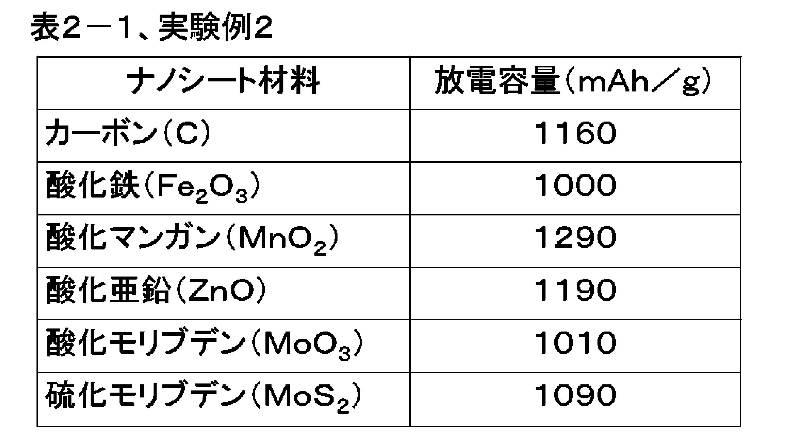

表2-1におけるいずれも、放電容量は、初回で1000mAh/g以上を示し、実施の形態2における実験例1のようなナノシートを含む共連続体よりも全体的に大きい値であった。これらのナノファイバーの例の場合も、カーボンナノファイバー同様、伸縮性を有する空気極が効率的に放電生成物[Mg(OH)2]を析出したため、放電容量が改善されたものと考えられる。
The discharge capacity in any of Table 2-1 at the first time was 1000 mAh / g or more, which was an overall larger value than the co-continuum including the nanosheet as in Experimental Example 1 in the second embodiment. Also in the case of these nanofiber examples, it is considered that the discharge capacity is improved because the stretchable air electrode efficiently deposits the discharge product [Mg (OH) 2 ] as in the carbon nanofibers.
また、表2-2におけるいずれも、放電容量は、初回で570mAh/g以上を示し、実施の形態2における実験例1のようなナノシートを含む共連続体よりも全体的に大きい値であった。これらのナノファイバーの例の場合も、カーボンナノファイバー同様、伸縮性を有する空気極が効率的に放電生成物(ZnO)を析出したため、放電容量が改善されたものと考えられる。
Further, in any of Table 2-2, the discharge capacity at the first time was 570 mAh / g or more, which was an overall larger value than the co-continuum including the nanosheet as in Experimental Example 1 in the second embodiment. . Also in the case of these nanofiber examples, it is considered that the discharge capacity is improved because the stretchable air electrode efficiently deposits the discharge product (ZnO) as in the carbon nanofibers.
[実験例3]
次に、実施の形態2における実験例3について説明する。実験例3では、カーボンナノファイバーによる共連続体に、酸化物または金属を触媒として担持させて構成した空気極について説明する。以下では、代表として、触媒としてMnO2を共連続体に担持させる場合について説明するが、Mnを任意の金属に変えることで、任意の酸化物を触媒として共連続体に担持させることができる。また、中和の工程を行わないことで、任意の金属を触媒として共連続体に担持させることができる。 [Experimental Example 3]
Next, Experimental Example 3 in the second embodiment will be described. In Experimental Example 3, an air electrode formed by supporting an oxide or a metal as a catalyst on a co-continuum of carbon nanofibers will be described. Although the case where MnO 2 is supported on a co-continuous as a catalyst will be described below as a representative, any oxide can be supported on the co-continuous as a catalyst by changing Mn to an arbitrary metal. In addition, by not performing the neutralization step, it is possible to load any metal as a catalyst on the co-continuum.
共連続体の評価法、空気電池の作製、充放電試験方法は、実施の形態2における実験例1,2と同様にして行った。共連続体は、実施の形態2における実験例2と同様に作製した。次に、市販の塩化マンガン(II)4水和物(RuCl2・4H2O;関東化学製)を蒸留水に溶解し、作製した共連続体を含浸させ、塩化マンガンを担持させた。次いで、塩化マンガンを担持する共連続体(共連続体が担持する塩化マンガン)に、徐々にアンモニア水(28%)をpH7.0になるまで滴下し、中和することで水酸化ルテニウムを析出させた。析出物は、塩素が残留しないように、蒸留水による洗浄を5回繰り返した。
The evaluation method of the co-continuum, the preparation of the air battery, and the charge / discharge test method were performed in the same manner as in Experimental Examples 1 and 2 in the second embodiment. The co-continuum was produced in the same manner as Experimental Example 2 in the second embodiment. Next, commercially available manganese (II) tetrahydrate (RuCl 2 .4H 2 O; made by Kanto Chemical Co., Ltd.) was dissolved in distilled water, and the prepared co-continuum was impregnated to carry manganese chloride. Next, ammonia water (28%) is gradually added dropwise to a co-continuum supporting manganese chloride (manganese chloride supported by the co-continuum) until the pH reaches 7.0 to precipitate ruthenium hydroxide by neutralization. I did. The precipitate was repeatedly washed five times with distilled water so that chlorine did not remain.
得られた水酸化マンガン担持共連続体を、アルゴン雰囲気中500℃で6時間熱処理し、酸化マンガン(MnO2)を担持した共連続体を作製した。作製した酸化マンガン担持共連続体を、XRD測定、TEM観察を行い、評価した。XRD測定より、酸化マンガン(MnO2,PDFファイルNo.00-011-079)のピークを観察することができた。共連続体に担持された触媒は、酸化マンガン単相であることを確認した。また、TEMにより酸化マンガンは、共連続体の表面に平均粒径100nmの粒子状で析出している状態が観察された。
The obtained manganese hydroxide-supporting co-continuum was heat-treated at 500 ° C. for 6 hours in an argon atmosphere to prepare a co-continuum supporting manganese oxide (MnO 2 ). The produced manganese oxide-supporting cocontinuum was evaluated by performing XRD measurement and TEM observation. From the XRD measurement, it was possible to observe a peak of manganese oxide (MnO 2 , PDF file No. 00-011-079). The catalyst supported on the co-continuous was confirmed to be a manganese oxide single phase. Further, it was observed by TEM that manganese oxide was precipitated in the form of particles having an average particle diameter of 100 nm on the surface of the co-continuous body.
この酸化マンガンを担持した共連続体を空気極に用いて実施の形態2における実験例1,2と同様のコインセル型の空気電池を作製した。作製した実施の形態2における実験例3における負極がマグネシウムの空気電池の放電容量は、1550mAh/gであった。また、実施の形態2における実験例3における負極が亜鉛の空気電池の放電容量は、710mAh/gであった。また、以下の表3-1,表3-2に、他の触媒を用いた場合の結果も合わせて示す。
The coin cell type air battery similar to Experimental Examples 1 and 2 in Embodiment 2 was manufactured using the co-continuum supporting the manganese oxide as an air electrode. The discharge capacity of the air battery with a negative electrode of magnesium in Experimental Example 3 of Embodiment 2 produced was 1550 mAh / g. Moreover, the discharge capacity of the air battery with a negative electrode of zinc in Experimental Example 3 in Embodiment 2 was 710 mAh / g. In addition, Tables 3-1 and 3-2 below also show the results when other catalysts are used.
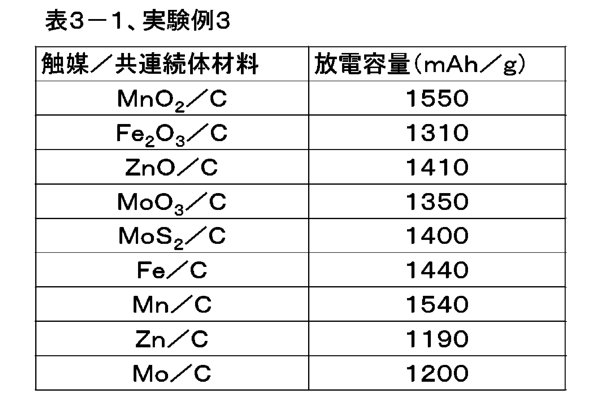
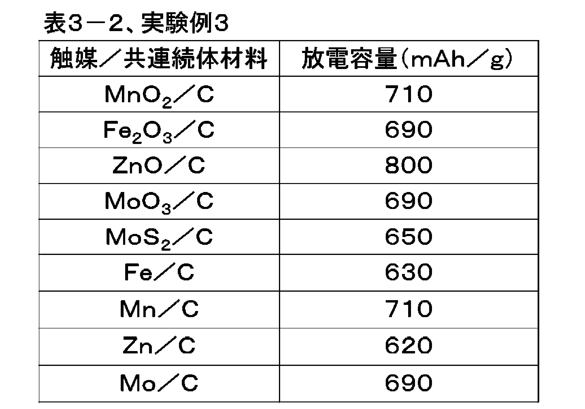
[実験例4]
次に、実施の形態2における実験例4について説明する。実験例4は、バクテリアに産生させたナノファイバーが分散したゲルによる共連続体に、更に、酸化マンガンを触媒として担持させた場合について説明する。以下では、代表として、鉄バクテリアが産生した酸化鉄によるナノファイバーから共連続体を作製した場合について示すが、鉄バクテリアを任意のバクテリアに変えることで、酸化マンガンによるナノファイバーによる共連続体を調整することができる。 [Experimental Example 4]
Next, Experimental Example 4 in the second embodiment will be described. Experimental Example 4 describes a case where manganese oxide is further supported as a catalyst on a co-continuum of gel in which nanofibers produced by bacteria are dispersed. In the following, the case where a co-continuum is prepared from iron oxide-produced nanofibers by iron bacteria is shown as a representative, but the iron oxide is changed to any bacteria to adjust the manganese oxide-bound nanofibers can do.
共連続体の評価法、空気電池の作製法、および放電試験方法は、実施の形態2における実験例1,2と同様にして行った。
The evaluation method of the co-continuum, the manufacturing method of the air battery, and the discharge test method were performed in the same manner as in Experimental Examples 1 and 2 in the second embodiment.
まず、鉄バクテリアであるレプトスリックス・オクラセア(Leptothrix ochracea)を、鉄小片(純度99.9%以上、高純度化学研究所製)と共に試験管中のJOP液体培地に投入し、振とう器で20℃、14日間培養した。JOP液体培地は、滅菌地下水1L中、リン酸水素二ナトリウム12水和物0.076g、リン酸二水素カリウム2水和物0.02g、HEPES[4-(2-hydroxyethyl)-1-piperazineethanesulfonic acid:緩衝液用物質]2.383g、硫酸鉄0.01mmol/L、pHを水酸化ナトリウム水溶液で7.0に調整した培地である。また、レプトスリックス・オクラセアは、ATCC(American Type Culture Collection)から購入した。
First, the iron bacterium Leptothrix ochracea is placed in a JOP liquid medium in a test tube together with small pieces of iron (purity 99.9% or more, high purity chemical laboratory manufactured), and 20 shakers. C. for 14 days. JOP liquid medium: 0.076 g of disodium hydrogen phosphate dodecahydrate, 0.02 g of potassium dihydrogen phosphate dihydrate in 1 L of sterile groundwater, HEPES [4- (2-hydroxyethyl) -1-piperazineethanesulfonic acid : Buffer material] 2.383 g, 0.01 mmol / L of iron sulfate, and the medium was adjusted to pH 7.0 with aqueous sodium hydroxide solution. In addition, Leptothrix ochracea was purchased from ATCC (American Type Culture Collection).
培養した後、鉄小片を取り除き、得られたゲルを純水中で振とう器を用いて24時間洗浄を行った。この洗浄においては、純水は3度交換した。洗浄したゲルを原料とし、実施の形態2における実験例1および実験例3に示したプロセスと同様に空気電池を作製した。
After incubation, the iron fragments were removed, and the obtained gel was washed in pure water using a shaker for 24 hours. In this cleaning, pure water was exchanged three times. Using the washed gel as a raw material, an air battery was produced in the same manner as the process shown in Experimental Example 1 and Experimental Example 3 in the second embodiment.
得られた、共連続体は、XRD測定、SEM観察、気孔率測定、引張試験、BET比表面積測定を行い、評価した。本発明で作製した共連続体はXRD測定よりアモルファス状のFe3O4およびγ-Fe2O3(Fe3O4,PDFカードNo.01-075-1372,γ-Fe2O3,PDFカードNo.00-039-1346)であることを確認した。
The obtained co-continuum was evaluated by performing XRD measurement, SEM observation, porosity measurement, tensile test, and BET specific surface area measurement. The co-continuum prepared in the present invention is amorphous Fe 3 O 4 and γ-Fe 2 O 3 (Fe 3 O 4 , PDF card No. 01-075-1372, γ-Fe 2 O 3 , PDF by XRD measurement) It confirmed that it was card No. 00-039-1346).
また、SEM観察により、直径1μmで中空状のナノファイバー(ナノチューブ)が連続に連なった、共連続体であることを確認した。また、水銀圧入法により共BET比表面積測定を測定したところ、800m2/gであった。また、水銀圧入法により共連続体の気孔率を測定したところ、95%以上であった。更に、引張試験の結果から、引張応力により歪が60%加えられても、弾性領域を超えず、応力印加前の形状に復元することを確認した。
Moreover, it confirmed that it was a co-continuous body in which hollow nanofibers (nanotubes) with a diameter of 1 μm were continuously connected by SEM observation. Moreover, it was 800 m < 2 > / g when co BET specific surface area measurement was measured by the mercury intrusion technique. Moreover, it was 95% or more when the porosity of the co-continuum was measured by the mercury intrusion method. Furthermore, from the results of the tensile test, it was confirmed that even if a strain of 60% was applied by tensile stress, the shape did not exceed the elastic region and was restored to the shape before stress application.
実施の形態2における実験例4における鉄バクテリア産生の酸化鉄ナノファイバーによる共連続体を、空気極に用いた空気電池(負極はマグネシウム)の、放電容量は、1770mAh/gであった。また、実施の形態2における実験例4における鉄バクテリア産生の酸化鉄ナノファイバーによる共連続体を空気極に用いた空気電池(負極は亜鉛)の、放電容量は、720mAh/gであった。また、以下の表4-1,表4-2に、他の共連続体を用いた場合の結果も合わせて示す。表4-1は、負極をマグネシウムから構成した空気電池の結果である。また、表4-2は、負極を亜鉛から構成した空気電池の結果である。
The discharge capacity of an air battery (anode is magnesium) in which an iron oxide-produced iron oxide nanofiber co-continuum of Experimental Example 4 in Embodiment 2 is used as the air electrode (the negative electrode is magnesium) was 1770 mAh / g. Moreover, the discharge capacity of the air battery (the negative electrode is zinc) using the co-continuum of iron oxide-produced iron oxide nanofibers of Experimental Example 4 in Embodiment 2 for the air electrode was 720 mAh / g. In addition, Tables 4-1 and 4-2 below also show the results when other co-continuums are used. Table 4-1 shows the results of air batteries in which the negative electrode was made of magnesium. Table 4-2 shows the results of air batteries in which the negative electrode was made of zinc.
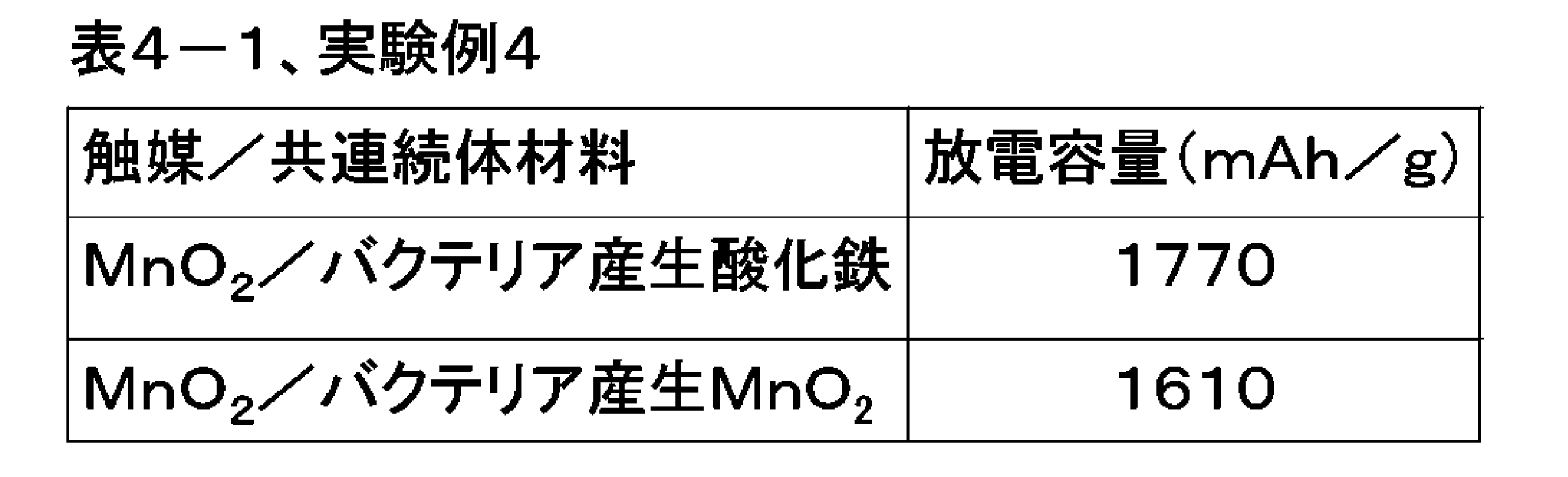

実施の形態2における実験例4では、負極をマグネシウムから構成した場合の放電容量は、初回で1770mAh/gを示し、実施の形態2における実験例3のような酸化マンガンを担持したカーボンナノファイバーによる共連続体を用いた場合よりもある程度大きい値となった。また、負極を亜鉛から構成した場合の放電容量は、初回で720mAh/gを示し、実施の形態2における実験例3のような酸化マンガンを担持したカーボンナノファイバーによる共連続体を用いた場合よりもある程度大きい値となった。これら結果は、より伸縮性の高い共連続体を用いることにより、放電時において円滑に反応が行われたことによると考えられる。
In Experimental Example 4 in Embodiment 2, the discharge capacity in the case where the negative electrode is formed of magnesium shows 1770 mAh / g at the first time, and the carbon nanofibers supporting manganese oxide as in Experimental Example 3 in Embodiment 2 The value was somewhat larger than when using a co-continuum. In addition, the discharge capacity in the case where the negative electrode is made of zinc shows 720 mAh / g at the first time, and it is more preferable than the case of using the co-continuum of carbon nanofibers supporting manganese oxide as in Experimental Example 3 in Embodiment 2. It also became a large value to some extent. These results are considered to be due to the smooth reaction at the time of discharge by using a more stretchable co-continuum.
また、表4-1に示すように、バクテリア産生酸化マンガンによる共連続体を用い、酸化マンガンを触媒とした空気極による空気電池(負極はマグネシウム)の放電容量は、初回で1610mAh/gを示し、実施の形態2における実験例3よりも大きい値であった。また、表4-2に示すように、バクテリア産生酸化マンガンによる共連続体を用い、酸化マンガンを触媒とした空気極による空気電池(負極は亜鉛)の放電容量は、初回で810mAh/gを示し、実施の形態2における実験例3よりも大きい値であった。
In addition, as shown in Table 4-1, the discharge capacity of the air battery (negative electrode is magnesium) by the air electrode catalyzed by manganese oxide was 1610 mAh / g at the first time using a co-continuum of bacteria-produced manganese oxide The value was larger than that of Experimental Example 3 in the second embodiment. In addition, as shown in Table 4-2, the discharge capacity of the air battery (negative electrode is zinc) by the air electrode catalyzed by manganese oxide as a co-continuum of bacterial produced manganese oxide is 810 mAh / g at the first time The value was larger than that of Experimental Example 3 in the second embodiment.
バクテリア産生酸化マンガンは、マンガン細菌であるレプトスリックス・ディスコフォラ(Leptothrix discophora)により、マンガン小片(純度99.9%以上、高純度化学研究所製)を用いて前述同様に培養して生産した。レプトスリックス・ディスコフォラは、ATCCから購入した。このバクテリア産生ナノファイバーの場合も、鉄バクテリア産生酸化鉄同様、バクテリアにより産生された優れた伸縮性を有する空気極が効率的に放電生成物を析出したため、放電容量が改善されたものと考えられる。
The bacterially produced manganese oxide was produced by culturing it in the same manner as described above using manganese small pieces (purity 99.9% or more, manufactured by High-Purity Chemical Laboratory) with the manganese bacterium Leptothrix discophora. Leptothrix discophora was purchased from ATCC. Also in the case of the bacteria-produced nanofibers, like the iron bacteria-produced iron oxide, the discharge electrode is efficiently deposited by the air electrode having excellent elasticity produced by the bacteria, and hence the discharge capacity is considered to be improved. .
[実験例5]
次に、実施の形態2における実験例5について説明する。実験例5は、バクテリアに産生させたセルロースが分散したゲルによる共連続体に、更に、酸化マンガンを触媒として担持させた場合について、共連続体の評価法、空気電池の作製法、および充放電試験方法は、実施の形態2における実験例1,2と同様にして行った。 [Experimental Example 5]
Next, Experimental Example 5 in the second embodiment will be described. Experimental example 5 is a method of evaluating cocontinuum, method of producing air battery, and charge and discharge in a case where manganese oxide is further supported as a catalyst on a cocontinuum of gel in which cellulose produced in bacteria is dispersed. The test method was carried out in the same manner as Experimental Examples 1 and 2 in the second embodiment.
まず、酢酸菌であるアセトバクター・キシリナム(Acetobacter xylinum)産生のバクテリアセルロースゲルとして、ナタデココ(フジッコ製)を用い、実施の形態2における実験例1および実験例3に示したプロセスと同様に空気電池を作製した。なお、実施の形態2における実験例5では、真空中で乾燥させた後、窒素雰囲気下で1200℃、2時間の焼成により、共連続体を炭化させ、これにより空気極を作製した。
First, as a bacterial cellulose gel produced by Acetobacter xylinum, which is an acetic acid bacterium, Natadecoco (Fujicco) is used, and an air battery is used in the same manner as the process shown in Example 1 and Example 3 in Embodiment 2. Was produced. In Experimental Example 5 of Embodiment 2, the co-continuum was carbonized by baking in a nitrogen atmosphere at 1200 ° C. for 2 hours after being dried in vacuum, whereby an air electrode was produced.
得られた、共連続体(炭化した共連続体)は、XRD測定、SEM観察、気孔率測定、引張試験、BET比表面積測定を行い、評価した。この共連続体は、XRD測定よりカーボン(C,PDFカードNo.01-071-4630)単相であることを確認した。また、SEM観察により、直径20nmのナノファイバーが連続に連なった、共連続体であることを確認した。また、水銀圧入法により共連続体のBET比表面積測定を測定したところ、830m2/gであった。また、水銀圧入法により共連続体の気孔率を測定したところ、99%以上であった。更に、引張試験の結果から、引張応力により歪が80%加えられても、弾性領域を超えず、応力印加前の形状に復元することを確認し、炭化した後も優れた伸縮性を有する。
The obtained co-continuum (carbonized co-continuum) was evaluated by performing XRD measurement, SEM observation, porosity measurement, tensile test, and BET specific surface area measurement. This co-continuum was confirmed to be carbon (C, PDF card No. 01-071-4630) single phase by XRD measurement. Moreover, it confirmed that it was a co-continuous body which the nanofiber of diameter 20 nm continued in a row by SEM observation. Moreover, it was 830 m < 2 > / g when BET specific surface area measurement of the co-continuum was measured by the mercury intrusion technique. Further, the porosity of the co-continuum was measured by mercury porosimetry and was 99% or more. Furthermore, from the results of the tensile test, it is confirmed that even if strain is applied by 80% by tensile stress, it does not exceed the elastic region and restores to the shape before stress application, and has excellent stretchability even after carbonization.
実施の形態2における実験例5における空気電池(負極はマグネシウム)の、放電容量を以下の表5-1に示す。また、実施の形態2における実験例5における空気電池(負極は亜鉛)の、放電容量を以下の表5-2に示す。表5-1,表5-2には、実施の形態2における実験例1,2,3,4の結果も示している。負極をマグネシウムとしている実験例5では、放電容量は、初回で1950mAh/gを示し、実施の形態2における実験例4のような酸化マンガンを担持した鉄バクテリア産生酸化鉄を含む共連続体を用いた場合よりも大きい値であった。また、負極を亜鉛としている実施の形態2における実験例5では、放電容量は、初回で810mAh/gを示し、実施の形態2における実験例4のような酸化マンガンを担持した鉄バクテリア産生酸化鉄を含む共連続体を用いた場合よりも大きい値であった。
The discharge capacities of the air battery (negative electrode is magnesium) in Experimental Example 5 in Embodiment 2 are shown in Table 5-1 below. The discharge capacity of the air battery (negative electrode is zinc) in Experimental Example 5 in Embodiment 2 is shown in Table 5-2 below. Tables 5-1 and 5-2 also show the results of Experimental Examples 1, 2, 3 and 4 in the second embodiment. In Experimental Example 5 in which the negative electrode is magnesium, the discharge capacity shows 1950 mAh / g at the first time, and a co-continuum containing iron bacteria-produced iron oxide supporting manganese oxide as in Experimental Example 4 in Embodiment 2 is used. It was a larger value than it was. Moreover, in Experimental example 5 in Embodiment 2 in which the negative electrode is zinc, the discharge capacity shows 810 mAh / g at the first time, and iron bacteria-produced iron oxide supporting manganese oxide as in Experimental Example 4 in Embodiment 2. The value was larger than when using a co-continuum including.
上記のような特性の向上は、より伸縮性の高い共連続体を用いることにより、放電時において効率的に放電生成物を析出したことと、Cが優れた導電性を有するために、円滑に反応が行われたと考えられる。
The above-mentioned characteristic improvement can be smoothly achieved by using the more stretchable co-continuum to deposit the discharge product efficiently at the time of discharge and because C has excellent conductivity. It is believed that a reaction has taken place.
上述したように、本発明により、高気孔率、BET比表面積測定で、伸縮性を有する共連続体が得られ、また、この共連続体を空気極に用いた空気電池によれば、放電時の効率的な放電生成物の析出が実現される。上記のような特性の向上は、本発明による各種の改善が理由と考えられる。
As described above, according to the present invention, a stretchable co-continuum is obtained by high porosity and BET specific surface area measurement, and according to an air battery using this co-continuum as an air electrode, it is possible to discharge Efficient discharge product deposition is realized. It is considered that the improvement of the characteristics as described above is due to various improvements by the present invention.
[実験例6]
次に、実施の形態2における実験例6について説明する。実験例6は、バクテリアに産生させたセルロースが分散したゲルによる共連続体に、更に、酸化マンガンを触媒として担持させた場合について、図7を用いて説明した筐体ごと自然分解される空気電池を作製した。酸化マンガンを触媒として担持させた共連続体の合成方法、共連続体の評価法、および充放電試験方法は、実施の形態2における実験例5と同様にして行った。 [Experimental Example 6]
Next, Experimental Example 6 in the second embodiment will be described. Experimental Example 6 is an air battery in which a case where the cellulose produced by bacteria is supported as a catalyst by dispersing manganese cellulose as a catalyst on the co-continuum of gel dispersed therein is also naturally decomposed as per the case described with reference to FIG. Was produced. The synthesis method of the co-continuum on which manganese oxide is supported as a catalyst, the evaluation method of the co-continuum, and the charge / discharge test method were performed in the same manner as in Experimental Example 5 in the second embodiment.
以下、実施の形態2における実験例6における空気電池の作製方法について説明する。負極をマグネシウムから構成する場合は、市販の金属マグネシウム板(厚さ200μm、ニラコ製)を、はさみを用いて20mm×20mmの正方形に切り抜くことで作製した。また、負極を亜鉛から構成するは、市販の金属亜鉛板(厚さ200μm、ニラコ製)を、はさみを用いて20mm×20mmの正方形に切り抜くことで作製した。
Hereinafter, a method of manufacturing the air battery in Experimental Example 6 in the second embodiment will be described. When the negative electrode is made of magnesium, it is manufactured by cutting a commercially available metal magnesium plate (thickness: 200 μm, manufactured by Niraco) into scissors of 20 mm × 20 mm square. The negative electrode was made of zinc by preparing a commercially available metallic zinc plate (200 μm thick, manufactured by Niraco) by cutting it into a 20 mm × 20 mm square using scissors.
電解液は、塩化カリウム(KCl、関東化学製)を1mol/Lの濃度で純水に溶解した溶液を用いた。セパレータは、電池用のセルロース系セパレータ(日本高度紙工業製)を25mm×25mmの正方形にカットして用いた。
The electrolyte used was a solution in which potassium chloride (KCl, manufactured by Kanto Chemical Co., Ltd.) was dissolved in pure water at a concentration of 1 mol / L. The separator was used by cutting a cellulose-based separator (made by Nippon High Paper Industry Co., Ltd.) for batteries into a square of 25 mm × 25 mm.
金属マグネシウム板からなる負極は、この周縁部をスポット溶接により負極集電体である銅メッシュ箔(MIT Japan製)に固定し、更に、この銅メッシュ箔を平面視で25mm×25mmにカットし、この端を、端子となる3×20mmにカットした銅箔(ニラコ製)の短辺にスポット溶接した。
The negative electrode made of a metal magnesium plate is fixed to a copper mesh foil (manufactured by MIT Japan), which is a negative electrode current collector, by spot welding this peripheral portion, and further cut this copper mesh foil into 25 mm × 25 mm in plan view, This end was spot-welded to the short side of a copper foil (manufactured by Niraco) cut into 3 × 20 mm as a terminal.
金属亜鉛板からなる負極は、この周縁部をスポット溶接により負極集電体である銅メッシュ箔(MIT Japan製)に固定し、更に、この銅メッシュ箔を平面視で25mm×25mmにカットし、この端を、端子となる3×20mmにカットした銅箔(ニラコ製)の短辺にスポット溶接した。
The negative electrode made of a metallic zinc plate is fixed to a copper mesh foil (manufactured by MIT Japan), which is a negative electrode current collector, by spot welding this peripheral portion, and this copper mesh foil is further cut into 25 mm × 25 mm in plan view, This end was spot-welded to the short side of a copper foil (manufactured by Niraco) cut into 3 × 20 mm as a terminal.
また、空気極用の集電体としての25mm×25mmにカットした銅メッシュ箔(MIT Japan製)に空気極を圧着し、この銅メッシュ箔の端に、端子となる3×20mmにカットした銅箔(ニラコ製)の短辺にスポット溶接した。
Also, the air electrode was crimped to a copper mesh foil (manufactured by MIT Japan) cut into 25 mm × 25 mm as a current collector for the air electrode, and the end cut of this copper mesh foil was cut into 3 × 20 mm as a terminal. Spot welding was performed on the short side of the foil (manufactured by Nirako).
筐体の材料として、植物系フィルムシート エコロージュ(三菱樹脂製)を用いた。このシートを平面視30m×30mmにカットした2枚のカットシートを作製し、一方を第1筐体とし、他方を第2筐体とした。また、正極側に用いる第2筐体には、中央部に15mm×15mmの開口を形成した。
A plant-based film sheet Ecologe (manufactured by Mitsubishi Plastics Co., Ltd.) was used as a material of the casing. Two cut sheets were prepared by cutting this sheet into a plan view of 30 m × 30 mm, one of which was used as a first case and the other as a second case. In addition, an opening of 15 mm × 15 mm was formed in the central portion of the second housing used on the positive electrode side.
負極側の第1筐体の上に、負極を固定した負極集電体およびセパレータを配置し、更にセパレータには電解液を注入した。この上に、空気極を圧着した空気極集電体、および第2筐体を被せ、第1筐体および第2の内側の周縁部(幅約5mm)を生分解性樹脂(ミヨシ油脂製)で接着して密閉した。このようにして、空気電池を作製した。
On the first housing on the negative electrode side, a negative electrode current collector on which the negative electrode was fixed and a separator were disposed, and an electrolyte was further injected into the separator. The air electrode current collector to which the air electrode is crimped and the second housing are placed on this, and the first housing and the second inner peripheral portion (about 5 mm in width) are biodegradable resin (made by Miyoshi Yushi) Bonded and sealed. Thus, an air battery was produced.
実施の形態2における実験例6における空気電池(負極はマグネシウム)の、放電容量を表5-1に示す。表5-1に示すように実施の形態2における実験例6では、放電容量は、初回で1880mAh/gを示し、実施の形態2における実験例5とほぼ同様の放電特性であった。また、実施の形態2における実験例6における空気電池(負極は亜鉛)の、放電容量を表5-2に示す。表5-2に示すように実施の形態2における実験例6では、放電容量は、初回で790mAh/gを示し、実施の形態2における実験例5とほぼ同様(95%以上)の放電特性であった。
The discharge capacity of the air battery (negative electrode is magnesium) in Experimental Example 6 in Embodiment 2 is shown in Table 5-1. As shown in Table 5-1, in Experimental Example 6 in Embodiment 2, the discharge capacity exhibited 1880 mAh / g at the first time, and the discharge characteristics were substantially the same as those of Experimental Example 5 in Embodiment 2. The discharge capacity of the air battery (negative electrode is zinc) in Experimental Example 6 in Embodiment 2 is shown in Table 5-2. As shown in Table 5-2, in Experimental Example 6 in Embodiment 2, the discharge capacity shows 790 mAh / g at the first time, and the discharge characteristics are almost the same (95% or more) as in Experimental Example 5 in Embodiment 2. there were.
実施の形態2における実験例6における空気電池を放電後に土壌中に設置したところ、約半月で筐体の分解が目視で確認でき、約1カ月後には完全に消失した。土壌中の微生物によって代謝され分解されたことが示された。
When the air battery according to Experimental Example 6 in Embodiment 2 was installed in the soil after discharging, the decomposition of the case could be visually confirmed in about half a month, and completely disappeared after about 1 month. It was shown to be metabolized and degraded by microorganisms in the soil.
[実験例7]
次に、実施の形態2における実験例7について説明する。実験例7は、実施の形態2における実験例6と同様の手順で作製した空気電池について、土壌を模擬した環境下で放電試験を行った。 [Experimental Example 7]
Next, Experimental Example 7 in the second embodiment will be described. In Experimental Example 7, a discharge test was performed on an air battery produced by the same procedure as Experimental Example 6 inEmbodiment 2 in an environment simulating soil.
次に、実施の形態2における実験例7について説明する。実験例7は、実施の形態2における実験例6と同様の手順で作製した空気電池について、土壌を模擬した環境下で放電試験を行った。 [Experimental Example 7]
Next, Experimental Example 7 in the second embodiment will be described. In Experimental Example 7, a discharge test was performed on an air battery produced by the same procedure as Experimental Example 6 in
実施の形態2における実験例7における空気電池(負極はマグネシウム)の、放電容量を表5-1に示す。表5-1に示すように実施の形態2における実験例7では、放電容量は、初回で1530mAh/gを示し、実施の形態2における実験例6よりも低下したが、土壌環境下においても問題なく作動することが示された。
The discharge capacity of the air battery (negative electrode is magnesium) in Experimental Example 7 in Embodiment 2 is shown in Table 5-1. As shown in Table 5-1, in the experimental example 7 in the second embodiment, the discharge capacity shows 1530 mAh / g at the first time, which is lower than the experimental example 6 in the second embodiment, but the problem also occurs in the soil environment. It was shown to work without.
実施の形態2における実験例7における空気電池(負極は亜鉛)の、放電容量を表5-2に示す。表5-2に示すように実施の形態2における実験例7では、放電容量は、初回で690mAh/gを示し、実施の形態2における実験例6よりも低下したが、土壌環境下においても問題なく作動することが示された。容量の低下要因としては、土壌中の温度が安定していないためであると考えられる。
The discharge capacities of the air battery (negative electrode is zinc) in Experimental Example 7 in Embodiment 2 are shown in Table 5-2. As shown in Table 5-2, in Experimental Example 7 in the second embodiment, the discharge capacity shows 690 mAh / g at the first time, which is lower than that of Experimental Example 6 in the second embodiment, but the problem is also in the soil environment. It was shown to work without. The cause of the decrease in volume is considered to be that the temperature in the soil is not stable.
また、実施の形態2における実験例7における空気電池を放電後に土壌中に放置したところ、放電試験開始時から約1カ月後には完全に消失した。
Further, when the air battery in Experimental Example 7 in Embodiment 2 was left in the soil after discharging, it completely disappeared about one month after the start of the discharge test.
[比較例1]
次に、比較例1について説明する。比較例1は、空気極用の電極として公知であるカーボン(ケッチェンブラックEC600JD)、および酸化マンガンを用いた空気電池セルを作製して評価した。比較例1では、実施の形態2における実験例1と同様のコインセル型の空気電池を作製した。 Comparative Example 1
Next, Comparative Example 1 will be described. The comparative example 1 produced and evaluated the air battery cell using carbon (Ketjen black EC600JD) and manganese oxide which are known as an electrode for air electrodes. In Comparative Example 1, a coin cell type air battery similar to that of Experimental Example 1 inEmbodiment 2 was manufactured.
次に、比較例1について説明する。比較例1は、空気極用の電極として公知であるカーボン(ケッチェンブラックEC600JD)、および酸化マンガンを用いた空気電池セルを作製して評価した。比較例1では、実施の形態2における実験例1と同様のコインセル型の空気電池を作製した。 Comparative Example 1
Next, Comparative Example 1 will be described. The comparative example 1 produced and evaluated the air battery cell using carbon (Ketjen black EC600JD) and manganese oxide which are known as an electrode for air electrodes. In Comparative Example 1, a coin cell type air battery similar to that of Experimental Example 1 in
酸化マンガン粉末(関東化学製)、ケッチェンブラック粉末(ライオン製)およびポリテトラフルオロエチレン(PTFE)粉末(ダイキン製)を50:30:20の重量比で、らいかい機を用いて十分に粉砕および混合し、ロール成形して、シート状電極(厚さ:0.5mm)を作製した。このシート状電極を直径14mmの円形に切り抜き空気極を得た。電池の放電試験の条件は、実施の形態2における実験例1と同様である。
Manganese oxide powder (Kanto Chemical), ketjen black powder (Lion), and polytetrafluoroethylene (PTFE) powder (Daikin) at a weight ratio of 50:30:20, sufficiently ground using a grinder. And it mixed and roll-formed and produced sheet-like electrode (thickness: 0.5 mm). The sheet electrode was cut into a circle having a diameter of 14 mm to obtain an air electrode. The conditions of the discharge test of the battery are the same as those of Experimental Example 1 in the second embodiment.
比較例1に係る空気電池(負極はマグネシウム)の放電容量を、実施の形態2における実験例1~7の結果とともに表5-1に示す。表5-1に示すように、比較例1の初回放電容量は、750mAh/gであり、実施の形態2における実験例1よりも小さな値を示した。
The discharge capacities of the air battery (the negative electrode is magnesium) according to Comparative Example 1 are shown in Table 5-1 together with the results of Experimental Examples 1 to 7 in the second embodiment. As shown in Table 5-1, the initial discharge capacity of Comparative Example 1 was 750 mAh / g, which was smaller than that of Experimental Example 1 in Embodiment 2.
比較例1に係る空気電池(負極AA園)の放電容量を、実施の形態2における実験例1~7の結果とともに表5-2に示す。表5-2に示すように、比較例1の初回放電容量は、360mAh/gであり、実施の形態2における実験例1よりも小さな値を示した。
The discharge capacities of the air battery (negative electrode AA) according to Comparative Example 1 are shown in Table 5-2 together with the results of Experimental Examples 1 to 7 in the second embodiment. As shown in Table 5-2, the initial discharge capacity of Comparative Example 1 was 360 mAh / g, which was smaller than that of Experimental Example 1 in Embodiment 2.
また、測定後に比較例1の空気極を観察したところ、空気極の一部が崩れて電解液中に分散しており、空気極の電極構造が破壊されている様子が見られた。
Further, when the air electrode of Comparative Example 1 was observed after the measurement, a part of the air electrode was broken and dispersed in the electrolytic solution, and it was observed that the electrode structure of the air electrode was broken.
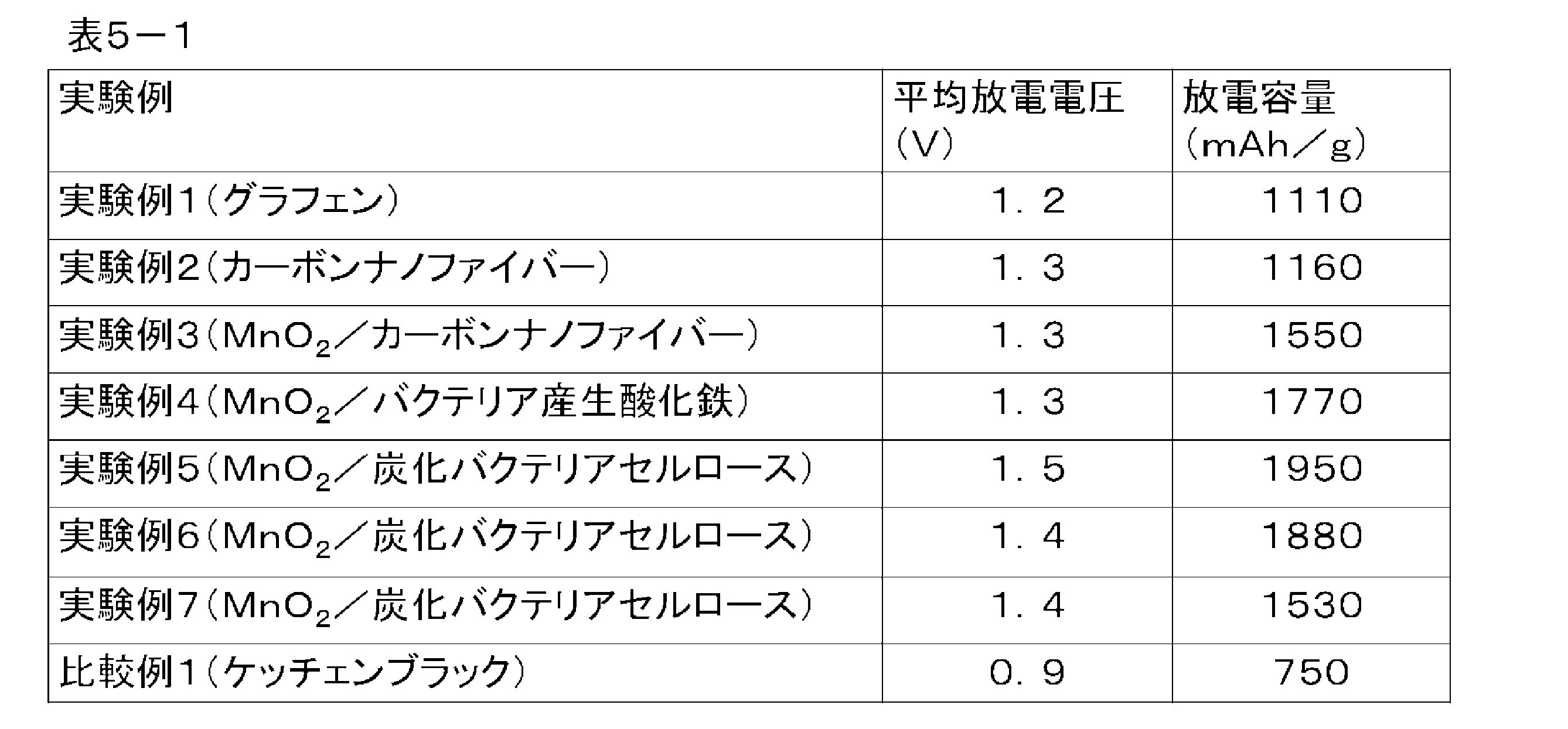

次に、実施の形態2における各実験例1~7,および比較例1について、負極をFeから構成した場合、および負極をAlから構成した場合の同様の結果について、以下の表6に示す。
Next, for each of Experimental Examples 1 to 7 and Comparative Example 1 in the second embodiment, the same results when the negative electrode is made of Fe and when the negative electrode is made of Al are shown in Table 6 below.
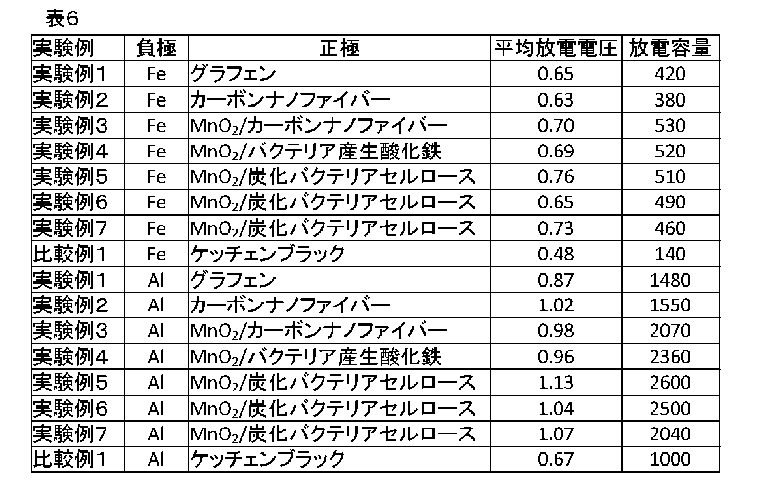
以上の結果より、実施の形態2における電池(空気電池)は、公知の材料による空気極を用いた空気電池よりも、容量および電圧に関して優れていることが確認された。
From the above results, it was confirmed that the battery (air battery) in the second embodiment is superior in capacity and voltage to an air battery using an air electrode made of a known material.
以上に説明したように、実施の形態2によれば、非共有結合によって一体とされた複数のナノ構造体からなる三次元ネットワーク構造とされた共連続体から空気極を構成したので、空気電池がより容易に取り扱えるようになる。実施の形態2における電池(空気電)池は、土壌の肥料に用いられる元素や雨水や海水中に含まれる金属以外の金属元素が含まれず、また、自然分解されるため、極めて環境負荷が低い。このような電池は、日常環境の使い捨て電池を始め、土壌中で用いるセンサーなどの様々な駆動源として有効利用することができる。また、実施の形態2によれば、電池の放電容量を大きくすることができる。
As described above, according to the second embodiment, since the air electrode is formed from the co-continuum formed into a three-dimensional network structure composed of a plurality of nanostructures integrated by non-covalent bonding, the air battery Can be handled more easily. The battery (aeroelectric) pond according to the second embodiment does not contain elements used for fertilizers in the soil or metal elements other than metals contained in rainwater or seawater and is naturally decomposed, so the environmental load is extremely low. . Such a battery can be effectively utilized as a disposable battery in a daily environment and various driving sources such as a sensor used in the soil. Further, according to the second embodiment, the discharge capacity of the battery can be increased.
[実施の形態3]
次に、本発明の実施の形態3における電池について、図11を用いて説明する。実施の形態3における電池は、正極121と、負極122と、正極121と負極122とに挾まれて配置されて、塩から構成された電解質123とを備える水電池である。負極122は、例えば、マグネシウム、鉄、アルミニウムなどを含んで構成されている。 Third Embodiment
Next, a battery according to the third embodiment of the present invention will be described using FIG. The battery according to the third embodiment is a water battery including apositive electrode 121, a negative electrode 122, and an electrolyte 123 which is disposed between the positive electrode 121 and the negative electrode 122 and is made of a salt. The negative electrode 122 contains, for example, magnesium, iron, aluminum or the like.
次に、本発明の実施の形態3における電池について、図11を用いて説明する。実施の形態3における電池は、正極121と、負極122と、正極121と負極122とに挾まれて配置されて、塩から構成された電解質123とを備える水電池である。負極122は、例えば、マグネシウム、鉄、アルミニウムなどを含んで構成されている。 Third Embodiment
Next, a battery according to the third embodiment of the present invention will be described using FIG. The battery according to the third embodiment is a water battery including a
水電池は、空気電池とは異なり、正極121の一方の面が大気に曝される必要はない。水電池では、正極121は水を活性物質とする。なお、電解質123は、電解液または固体電解質のいずれであってもよい。電解液とは、電解質が液体形態である場合をいう。また、固体電解質とは、電解質がゲル形態または固体形態である場合をいう。
Unlike the air battery, in the water battery, one side of the positive electrode 121 does not have to be exposed to the atmosphere. In a water battery, the positive electrode 121 uses water as an active substance. The electrolyte 123 may be either an electrolytic solution or a solid electrolyte. The electrolytic solution refers to the case where the electrolyte is in a liquid form. Moreover, a solid electrolyte means the case where an electrolyte is a gel form or a solid form.
実施の形態3における電池(水電池)は、正極121が、一体とされた複数のナノ構造体が分岐を有することで三次元ネットワーク構造とされた共連続体から構成されている。例えば、複数のナノ構造体は、非共有結合によって一体とされている。共連続体は、多孔体であり、一体構造とされている。ナノ構造体は、ナノシートあるいはナノファイバーである。一体とされた複数のナノ構造体が分岐を有することで三次元ネットワーク構造の共連続体は、ナノ構造体同士の分岐部が変形可能とされており、伸縮性を有した構造となっている。
In the battery (water battery) according to the third embodiment, the positive electrode 121 is composed of a co-continuum in which a plurality of integrated nanostructures have a branch to form a three-dimensional network structure. For example, the plurality of nanostructures are united by non-covalent bonding. The co-continuous body is a porous body and has an integral structure. The nanostructures are nanosheets or nanofibers. By having a plurality of integrated nanostructures having branches, the bi-continuous structure of the three-dimensional network structure is such that the branched portions of the nanostructures can be deformed and has a stretchable structure .
ナノシートは、例えば、カーボン、酸化鉄、酸化マンガン、酸化マグネシウム、酸化モリブデン、硫化モリブデン化合物の少なくとも1つから構成されたものであればよい。硫化モリブデン化合物は、例えば、二硫化モリブデン、リンドープ硫化モリブデンなどである。これらの材料の元素は、植物の生育に不可欠な16種類の必須元素(C,O,H,N,P,K,S,Ca,Mg,Fe,Mn,B,Zn,Cu,Mo,Cl)から構成されていれば良い。また、これらの材料の元素は、植物の生育に有用な、Na,Si,Se,Co,Al,Vから構成されていてもよい。
The nanosheet may be made of, for example, at least one of carbon, iron oxide, manganese oxide, magnesium oxide, molybdenum oxide, and a sulfurized molybdenum compound. The sulfurized molybdenum compound is, for example, molybdenum disulfide, phosphorus-doped molybdenum sulfide or the like. The elements of these materials are 16 essential elements essential for plant growth (C, O, H, N, P, K, S, Ca, Mg, Fe, Mn, B, Zn, Cu, Mo, Cl It should just consist of). The elements of these materials may also be composed of Na, Si, Se, Co, Al, V, which are useful for plant growth.
ナノシートは導電性を有することが重要である。ナノシートは、厚さが1nmから1μmであり、平面縦横長さが、厚さの100倍以上のシート状物質と定義する。例えば、カーボンによるナノシートとしてグラフェンがある。また、ナノシートは、ロール状、波状であっても良く、ナノシートが湾曲や屈曲していても良く、どのような形状であってもよい。
It is important that the nanosheets have conductivity. The nanosheet is defined as a sheet-like material having a thickness of 1 nm to 1 μm and a planar longitudinal length of 100 times or more of the thickness. For example, there is graphene as a nanosheet of carbon. In addition, the nanosheet may be in the form of a roll or a wave, the nanosheet may be curved or bent, and may have any shape.
ナノファイバーは、カーボン、酸化鉄、酸化マンガン、酸化マグネシウム、酸化モリブデン、硫化モリブデン、およびセルロース(炭化したセルロース)の少なくとも1つから構成されたものであればよい。これらの材料の元素は、植物の生育に不可欠な16種類の必須元素(C,O,H,N,P,K,S,Ca,Mg,Fe,Mn,B,Zn,Cu,Mo,Cl)から構成されていれば良い。また、これらの材料の元素は、植物の生育に有用な、Na,Si,Se,Co,Al,Vから構成されていてもよい。
The nanofibers may be made of at least one of carbon, iron oxide, manganese oxide, magnesium oxide, molybdenum oxide, molybdenum sulfide, and cellulose (carbonized cellulose). The elements of these materials are 16 essential elements essential for plant growth (C, O, H, N, P, K, S, Ca, Mg, Fe, Mn, B, Zn, Cu, Mo, Cl It should just consist of). The elements of these materials may also be composed of Na, Si, Se, Co, Al, V, which are useful for plant growth.
ナノファイバーも導電性を有することが重要である。ナノファイバーは、直径が1nmから1μmであり、長さが直径の100倍以上の繊維状物質と定義する。また、ナノファイバーは、中空状、コイル状であっても良く、どのような形状であってもよい。なお、セルロースについては、後述するように、炭化により導電性を持たせて用いる。
It is important that the nanofibers also have conductivity. Nanofibers are defined as fibrous materials having a diameter of 1 nm to 1 μm and a length of 100 times or more of the diameter. The nanofibers may be hollow or coiled, and may have any shape. In addition, about the cellulose, as described later, it is used by giving conductivity by carbonization.
例えば、まず、ナノ構造体が分散したゾルまたはゲルを凍結させて凍結体とし(凍結工程)、この凍結体を真空中で乾燥させる(乾燥工程)ことで、正極121とする共連続体を作製することができる。鉄酸化物,マンガン酸化物、セルロースのいずれかによるナノファイバーが分散したゲルであれば、所定のバクテリアに生産させることができる(ゲル生産工程)。
For example, first, a sol or gel in which nanostructures are dispersed is frozen to form a frozen body (freezing step), and the frozen body is dried in vacuum (drying step) to produce a co-continuum serving as the positive electrode 121 can do. If it is a gel in which nanofibers of iron oxide, manganese oxide, or cellulose are dispersed, it can be produced by predetermined bacteria (gel production process).
また、所定のバクテリアに、セルロースによるナノファイバーが分散したゲルを生産させ(ゲル生産工程)、このゲルを不活性ガスの雰囲気で加熱して炭化することで、共連続体を得る(炭化工程)ようにしてもよい。
In addition, a gel is produced in which nanofibers of cellulose are dispersed in predetermined bacteria (gel production process), and the gel is carbonized by heating in an inert gas atmosphere to obtain a co-continuum (carbonization process) You may do so.
正極121を構成する共連続体は、例えば、平均孔径が0.1~50μmであることが好ましく、0.1~2μmであることが更に好ましい。ここで、平均孔径は、水銀圧入法により求めた値である。
The co-continuum constituting the positive electrode 121 preferably has, for example, an average pore diameter of 0.1 to 50 μm, and more preferably 0.1 to 2 μm. Here, the average pore size is a value determined by mercury porosimetry.
正極121には、カーボン粉末を用いた場合のようなバインダーなどの追加の材料を用いる必要がなく、コスト的に有利であり環境面でも有利である。
The positive electrode 121 does not need to use an additional material such as a binder as in the case of using a carbon powder, which is advantageous in cost and environmental advantage.
ここで、正極121および負極122における電極反応について説明する。正極反応は、導電性を有する正極121の表面において、水(電解質123)が接することで、「2H2O+2e-→2OH-+H2・・・(6)」で示す反応が進行する。一方、マグネシウムから構成した場合の負極反応は、電解質123に接している負極122において「Mg→Mg2++2e-・・・(7)」の反応が進行し、負極122を構成しているマグネシウムが電子を放出し、電解質123中にマグネシウムイオンとして溶解する。
Here, the electrode reaction in the positive electrode 121 and the negative electrode 122 will be described. In the positive electrode reaction, the reaction shown by “2H 2 O + 2e − → 2OH − + H 2 (6)” progresses when water (electrolyte 123) is in contact with the surface of the conductive positive electrode 121 having conductivity. On the other hand, in the case of the negative electrode reaction in the case of being composed of magnesium, the reaction of “Mg → Mg 2+ +2 e − (7)” proceeds in the negative electrode 122 in contact with the electrolyte 123, and magnesium constituting the negative electrode 122 Emits electrons and dissolves in the electrolyte 123 as magnesium ions.
これらの反応により、放電を行うことが可能である。全反応は、「Mg+2H2O+2e-→Mg(OH)2+H2・・・(8)」となり、水酸化マグネシウムと水素が生成する反応である。理論起電力は約1.4Vである。以上の反応に関わる化合物を、図1の構成要素と共に示している。
It is possible to perform discharge by these reactions. The entire reaction is a reaction of “Mg + 2H 2 O + 2e − → Mg (OH) 2 + H 2 ... (8)” to generate magnesium hydroxide and hydrogen. The theoretical electromotive force is about 1.4V. The compounds involved in the above reaction are shown together with the components in FIG.
このように、水電池は、正極121の表面において式(6)で示す反応が進行するため、正極121の内部に反応サイトを多量に生成する方がよいものと考えられる。
As described above, in the water battery, since the reaction represented by the formula (6) proceeds on the surface of the positive electrode 121, it is considered preferable to generate a large amount of reaction sites inside the positive electrode 121.
正極である正極121は、カーボン粉末をバインダーで成形するといった公知のプロセスで作製することができるが、上述した通り、実施の形態3における電池(水電池)では、正極121内部に反応サイトを多量に生成することが重要であり、正極121は、高比表面積であることが望ましい。例えば、本発明においては、正極121を構成する共連続体の比表面積が200m2/g以上であることが好ましく300m2/g以上であることがより好ましい。
The positive electrode 121, which is a positive electrode, can be manufactured by a known process of forming carbon powder with a binder, but as described above, in the battery (water battery) in the third embodiment, a large amount of reaction sites are inside the positive electrode 121. It is important that the positive electrode 121 have a high specific surface area. For example, in the present invention, the specific surface area of the co-continuum constituting the positive electrode 121 is preferably 200 m 2 / g or more, and more preferably 300 m 2 / g or more.
カーボン粉末をバインダーで成形してペレット化することで作製している従来の正極の場合、高比表面積化した際に、カーボン粉末同士の結着強度が低下し、構造が劣化することで、安定して放電することが困難であり、放電容量が低下する。
In the case of a conventional positive electrode produced by forming and pelletizing carbon powder with a binder, when the specific surface area is increased, the binding strength between the carbon powders is reduced, and the structure is degraded, thereby achieving stability. Discharge is difficult, and the discharge capacity is reduced.
これに対し、前述したように一体とされた複数のナノ構造体が分岐を有することで三次元ネットワーク構造とされた共連続体により構成した本発明の正極121によれば、上述した従来の問題が解消でき、放電容量を高くできるようになる。
On the other hand, according to the positive electrode 121 of the present invention, in which the plurality of integrated nano-structures have a branch as described above and is configured by a co-continuous body having a three-dimensional network structure, the above-described conventional problems Can be eliminated, and the discharge capacity can be increased.
また、正極121は、触媒を担持していてもよい。触媒は、鉄、マンガン、亜鉛、銅、モリブデンの少なくとも1つの金属、あるいは、カルシウム、鉄、マンガン、亜鉛、銅、モリブデンの少なくとも1つの金属からなる金属酸化物から構成されていればよい。なお、これらの材料の元素は、植物の生育に不可欠な16種類の必須元素に含まれる金属から構成され、触媒能を有していれば良い。また、これらの材料の元素は、植物の生育に有用な、Na,Si,Se,Co,Al,Vから構成されていてもよい。金属としては、鉄、マンガン、亜鉛が好ましく、これらの1つからなる酸化物または2つ以上からなる複合酸化物が好ましい。また、特に、酸化マンガン(MnO2)が好適である。酸化マンガンは、本発明において特に優れた触媒性能を示すので好ましい。
In addition, the positive electrode 121 may support a catalyst. The catalyst may be composed of at least one metal of iron, manganese, zinc, copper and molybdenum, or a metal oxide composed of at least one metal of calcium, iron, manganese, zinc, copper and molybdenum. In addition, the element of these materials is comprised from the metal contained in 16 types of essential elements essential to the growth of a plant, and it should just have catalytic ability. The elements of these materials may also be composed of Na, Si, Se, Co, Al, V, which are useful for plant growth. The metal is preferably iron, manganese or zinc, and an oxide of one of them or a composite oxide of two or more is preferable. In particular, manganese oxide (MnO 2 ) is preferable. Manganese oxide is preferred because it exhibits particularly excellent catalytic performance in the present invention.
また、触媒とする金属酸化物は、水和物としたアモルファス状のものであることも好ましい。例えば、上述した遷移金属酸化物の水和物であればよい。より具体的には、酸化マンガン(IV)-n水和物であればよい。なお、nは、1molのMnO2に対するH2Oのモル数である。正極121を構成する共連続体の表面に、酸化マンガンの水和物を、ナノサイズの微粒子として高分散で担持させることで、優れた電池性能とすることが可能となる。
Moreover, it is also preferable that the metal oxide used as a catalyst is a hydrate-like amorphous thing. For example, it may be a hydrate of the transition metal oxide described above. More specifically, it may be manganese (IV) oxide-n-hydrate. Here, n is the number of moles of H 2 O relative to 1 mol of MnO 2 . It is possible to achieve excellent battery performance by supporting the hydrate of manganese oxide in the form of nano-sized particles with high dispersion on the surface of the co-continuum constituting the positive electrode 121.
例えば、正極121の共連続体上に、酸化マンガン水和物(MnO2・nH2O)をナノサイズの微粒子として高分散で付着させた(添加した)ものを正極121として使用することで、優れた電池性能を示すことが可能となる。正極121に含まれる触媒の含有量は、正極121の総重量に基づいて、0.1~70重量%、好ましくは1~30重量%である。正極121に、遷移金属酸化物を触媒として添加することによって、電池性能は大きく向上する。正極121中に電解質123の電解液が浸透し、上述したような電解液-電極の界面が形成される。この界面サイトにおいて、触媒が高活性であれば、電極表面における水還元(放電)が円滑に進行し、電池性能は大きく向上することになる。
For example, by using, as the positive electrode 121, highly dispersed (added) manganese oxide hydrate (MnO 2 · n H 2 O) as nano-sized fine particles on the co-continuum of the positive electrode 121 It is possible to show excellent battery performance. The content of the catalyst contained in the positive electrode 121 is 0.1 to 70% by weight, preferably 1 to 30% by weight, based on the total weight of the positive electrode 121. By adding a transition metal oxide as a catalyst to the positive electrode 121, the battery performance is greatly improved. The electrolyte solution of the electrolyte 123 penetrates into the positive electrode 121, and the above-described electrolyte-electrode interface is formed. At this interface site, if the catalyst is highly active, water reduction (discharge) on the electrode surface proceeds smoothly, and the battery performance is greatly improved.
水電池では、上述した通り、電池の効率を上げるために、電極反応を引き起こす反応部位[上記の電解液/電極の界面部分]がより多く存在することが望ましい。このような観点から、上述の界面部位が触媒の表面にも多量に存在することが重要であり、触媒は比表面積が高い方が好ましい。金属または金属酸化物による触媒の比表面積は、0.1~1000m2/g、好ましくは1~500m2/gであればよい。なお、比表面積は、公知のN2吸着によるBET法により求めた比表面積である。
In the water battery, as described above, in order to increase the efficiency of the battery, it is desirable that more reaction sites causing the electrode reaction [the above-mentioned electrolyte / electrode interface portion] be present. From such a viewpoint, it is important that the above-mentioned interface site is also present in a large amount on the surface of the catalyst, and the catalyst preferably has a high specific surface area. The specific surface area of the metal or metal oxide catalyst may be 0.1 to 1000 m 2 / g, preferably 1 to 500 m 2 / g. The specific surface area is the specific surface area determined by the BET method by known N 2 adsorption.
触媒を添加した正極121は、後述する正極121の製造方法により製造することができる。
The positive electrode 121 to which the catalyst is added can be manufactured by the method of manufacturing the positive electrode 121 described later.
次に、負極122について説明する。負極122は、負極活性物質から構成する。この負極活性物質は、水電池の負極材料として用いることができる材料、つまり、金属マグネシウム、マグネシウム含有物質、金属鉄、鉄含有物質、金属アルミニウム、アルミニウム含有物質を含むものであれば特に限定されない。例えば、負極122は、金属マグネシウム、金属マグネシウムのシート、またはマグネシウム粉末を銅などの金属箔に圧着したものなどから構成すればよい。
Next, the negative electrode 122 will be described. The negative electrode 122 is composed of a negative electrode active material. The negative electrode active material is not particularly limited as long as it is a material that can be used as a negative electrode material of a water battery, that is, it contains metallic magnesium, a magnesium-containing substance, metallic iron, an iron-containing substance, metallic aluminum, and an aluminum-containing substance. For example, the negative electrode 122 may be made of metal magnesium, a sheet of metal magnesium, or a material obtained by pressure bonding a magnesium powder to a metal foil such as copper.
負極122は、公知の方法で形成することができる。例えば、マグネシウム金属を負極122とする場合には、複数枚の金属マグネシウム箔を重ねて所定の形状に成形することで、負極122を作製することもできる。
The negative electrode 122 can be formed by a known method. For example, in the case where magnesium metal is used as the negative electrode 122, the negative electrode 122 can also be manufactured by stacking a plurality of metal magnesium foils and forming the same into a predetermined shape.
次に、電解質123について説明する。電解質123は、正極121および負極122間で、負極122を構成する金属(例えばマグネシウム)のイオンおよび水酸化物イオンの移動が可能な物質であればよい。例えば、地球上に豊富に存在するカリウムやナトリウムが含まれる金属塩を挙げることができる。なお、この金属塩は、植物の生育に不可欠な16種類の必須元素(C,O,H,N,P,K,S,Ca,Mg,Fe,Mn,B,Zn,Cu,Mo,Cl)や海水や雨水に含まれる元素から構成されていれば良い。電解質123は、例えば、塩化ナトリウムや塩化カリウムから構成すればよい。カリウムは、肥料成分の中でも多量要素の1つであるため、仮に電解質が土壌に漏れ出たときの影響を与えないのみならず、肥料として機能するため、特に、塩化カリウムが好ましい。
Next, the electrolyte 123 will be described. The electrolyte 123 may be any substance that can move ions of metal (for example, magnesium) constituting the negative electrode 122 and hydroxide ions between the positive electrode 121 and the negative electrode 122. For example, metal salts containing potassium and sodium abundantly present on the earth can be mentioned. This metal salt is one of 16 essential elements essential for plant growth (C, O, H, N, P, K, S, Ca, Mg, Fe, Mn, B, Zn, Cu, Mo, Cl ) And elements contained in seawater and rainwater. The electrolyte 123 may be made of, for example, sodium chloride or potassium chloride. Since potassium is one of the major components among the fertilizer components, potassium chloride is particularly preferable because it functions as a fertilizer as well as not only affecting the electrolyte leakage into the soil.
また、電解質123を構成する他の材料として、マグネシウムイオンおよび水酸化物イオンを通すイオン導電性を有する芳香族アニオン交換ポリマー固体電解質や無機層状化合物系固体電解質を用いても良い。
Moreover, as another material which comprises the electrolyte 123, you may use the aromatic anion exchange polymer solid electrolyte which has ion conductivity which allows magnesium ion and hydroxide ion to pass, and an inorganic layered compound type | system | group solid electrolyte.
なお、水電池は、上記構成に加え、セパレータ、電池ケース、金属箔(例えば銅箔)などの構造部材、また、一般的な空気電池に要求される要素を含むことができる。これらは、従来公知のものを使用することができる。セパレータとしては、繊維材料であれば特に限定されないが、植物繊維またはバクテリアからつくられるセルロース系セパレータが特に好ましい。
In addition to the above configuration, the water battery can include structural members such as a separator, a battery case, a metal foil (for example, copper foil), and elements required for a general air battery. As these, conventionally known ones can be used. The separator is not particularly limited as long as it is a fiber material, but a cellulose-based separator made of plant fibers or bacteria is particularly preferable.
次に、実施の形態3における製造方法について説明する。実施の形態3における水電池は、後述する正極製造方法により得られる正極121、負極122、電解質123を、所望の水電池の構造に基づいた他の必要な要素と共に、ケースなどの適切な容器内に適切に配置することで作製することができる。これらの水電池の製造手順は、従来知られている一般的な空気電池の方法を適用することができる。
Next, the manufacturing method in the third embodiment will be described. In the water battery according to the third embodiment, the positive electrode 121, the negative electrode 122 and the electrolyte 123 obtained by the positive electrode manufacturing method described later, together with other necessary elements based on the desired structure of the water battery, are housed in a suitable container such as a case. It can be produced by arranging it properly. The manufacturing procedure of these water cells can apply the method of the general air cell known conventionally.
以下、正極121の作製について説明する。
Hereinafter, preparation of the positive electrode 121 will be described.
[製造方法1]
はじめに、実施の形態3における製造方法1について図12を用いて説明する。まず、ステップS111で、ナノシートやナノファイバーなどのナノ構造体が分散したゾルまたはゲルを凍結させて凍結体を得る(凍結工程)。次に、ステップS112で、得られた凍結体を真空中で乾燥させて共連続体を得る(乾燥工程)。 [Manufacturing method 1]
First, themanufacturing method 1 in the third embodiment will be described with reference to FIG. First, in step S111, a sol or gel in which nanostructures such as nanosheets and nanofibers are dispersed is frozen to obtain a frozen body (freeze step). Next, in step S112, the obtained frozen body is dried in vacuum to obtain a co-continuum (drying step).
はじめに、実施の形態3における製造方法1について図12を用いて説明する。まず、ステップS111で、ナノシートやナノファイバーなどのナノ構造体が分散したゾルまたはゲルを凍結させて凍結体を得る(凍結工程)。次に、ステップS112で、得られた凍結体を真空中で乾燥させて共連続体を得る(乾燥工程)。 [Manufacturing method 1]
First, the
以下、各工程についてより詳細に説明する。ステップS111の凍結工程は、一体とされた複数のナノ構造体が分岐を有することで三次元ネットワーク構造とされた伸縮性を有する共連続体の原料となるナノ構造体を用い、三次元ネットワーク構造を維持または構築する工程である。
Each step will be described in more detail below. In the freezing step of step S111, a plurality of integrated nanostructures have branches, and the nanostructure is used as a raw material of a stretchable bicontinuous body formed into a three-dimensional network structure, and a three-dimensional network structure Maintenance or construction.
ここで、ゲルとは、分散媒が分散質であるナノ構造体の三次元ネットワーク構造により流動性を失い固体状になったものを意味する。具体的には、ずり弾性率が102~106Paである分散系を意味する。ゲルの分散媒は、水(H2O)などの水系または、カルボン酸、メタノール(CH3OH)、エタノール(C2H5OH)、プロパノール(C3H7OH)、n-ブタノール、イソブタノール、n-ブチルアミン、ドデカン、不飽和脂肪酸、エチレングリコール、ヘプタン、ヘキサデカン、イソアミルアルコール、オクタノール、イソプロパノール、アセトン、グリセリンなどの有機系であり、これらから2種類以上を混合してもよい。
Here, gel means that the dispersion medium loses fluidity and becomes solid due to the three-dimensional network structure of the nanostructure which is a dispersoid. Specifically, it means a dispersion having a shear modulus of 10 2 to 10 6 Pa. The dispersion medium of the gel may be an aqueous system such as water (H 2 O) or a carboxylic acid, methanol (CH 3 OH), ethanol (C 2 H 5 OH), propanol (C 3 H 7 OH), n-butanol, iso Organic systems such as butanol, n-butylamine, dodecane, unsaturated fatty acid, ethylene glycol, heptane, hexadecane, isoamyl alcohol, octanol, isopropanol, acetone, glycerin and the like, and two or more of these may be mixed.
次に、ゾルとは、分散媒および分散質であるナノ構造体からなるコロイドを意味する。具体的には、ずり弾性率が1Pa以下である分散系を意味する。ゾルの分散媒は、水などの水系または、カルボン酸、メタノール、エタノール、プロパノール、n-ブタノール、イソブタノール、n-ブチルアミン、ドデカン、不飽和脂肪酸、エチレングリコール、ヘプタン、ヘキサデカン、イソアミルアルコール、オクタノール、イソプロパノール、アセトン、グリセリンなどの有機系であり、これらから2種類以上を混合してもよい。
Next, a sol means a colloid composed of a dispersion medium and a nanostructure which is a dispersoid. Specifically, it means a dispersion system having a shear modulus of 1 Pa or less. The dispersion medium of the sol may be an aqueous system such as water, carboxylic acid, methanol, ethanol, propanol, n-butanol, isobutanol, n-butylamine, dodecane, unsaturated fatty acid, ethylene glycol, heptane, hexadecane, isoamyl alcohol, octanol, It is an organic system such as isopropanol, acetone, glycerin and the like, and two or more of them may be mixed.
凍結工程は、例えば、ナノ構造体が分散したゾルまたはゲルを試験管のような適切な容器に収容し、液体窒素などの冷却材中で試験管の周囲を冷却することで、試験管に収容したゾルまたはゲルを凍結することで実施される。凍結させる手法は、ゲルまたはゾルの分散媒を凝固点以下に冷却ができれば、特に限定されるものではなく、冷凍庫などで冷却してもよい。
In the freezing step, for example, the sol or gel in which the nanostructures are dispersed is housed in a suitable container such as a test tube, and is stored in the test tube by cooling the periphery of the test tube in a coolant such as liquid nitrogen It is carried out by freezing the sol or gel. The method of freezing is not particularly limited as long as the dispersion medium of gel or sol can be cooled to the freezing point or lower, and may be cooled by a freezer or the like.
ゲルまたはゾルを凍結することで、分散媒が流動性を失い分散質が固定され、三次元ネットワーク構造が構築される。また、凍結工程では、ゲルまたはゾルの濃度を調整することで比表面積を自在に調整でき、ゲルまたはゾルの濃度を薄くするほど、得られる共連続体は高比表面積となる。ただし、濃度が0.01重量%以下となると、分散質が三次元ネットワーク構造を構築することが困難となるため、分散質の濃度は、0.01~10重量%以下が好適である。
By freezing the gel or sol, the dispersion medium loses its fluidity and the dispersoid is fixed, whereby a three-dimensional network structure is constructed. In the freezing step, the specific surface area can be freely adjusted by adjusting the concentration of the gel or sol, and the thinner the concentration of the gel or sol, the higher the specific surface area of the obtained co-continuum. However, since it becomes difficult for the dispersoid to construct a three-dimensional network structure when the concentration is 0.01 wt% or less, the concentration of the dispersoid is preferably 0.01 to 10 wt% or less.
ナノファイバーまたはナノシートなどのナノ構造体で高比表面積な三次元ネットワーク構造を構築することで、圧縮または引張の際に、気孔がクッションの役割を果たし、優れた伸縮性を有する。具体的には、共連続体は、弾性限界での歪みが5%以上であることが望ましく、更に10%以上であることが更に望ましい。
By constructing a high specific surface area three-dimensional network structure with nanostructures such as nanofibers or nanosheets, the pores play a cushioning role during compression or tension and have excellent stretchability. Specifically, the co-continuum preferably has a strain at the elastic limit of 5% or more, and more preferably 10% or more.
凍結により分散質を固定しない場合、この後の乾燥工程において、分散媒の蒸発に伴い、分散質が凝集するため、十分な高比表面積を得ることができず、三次元ネットワーク構造を有する共連続体の作製は困難となる。
If the dispersoid is not fixed by freezing, in the subsequent drying step, the dispersoid coagulates with evaporation of the dispersion medium, so a sufficiently high specific surface area can not be obtained, and co-continuous having a three-dimensional network structure The preparation of the body becomes difficult.
次に、ステップS112の乾燥工程について説明する。乾燥工程では、凍結工程で得た凍結体より、三次元ネットワーク構造を維持または構築した分散質(一体とされている複数の微細構造体)を分散媒から取り出す工程である。
Next, the drying process of step S112 will be described. The drying step is a step of taking out from the dispersion medium the dispersoid (a plurality of integrated fine structures) in which the three-dimensional network structure is maintained or constructed from the frozen body obtained in the freezing step.
乾燥工程では、凍結工程で得られた凍結体を真空中で乾燥させ、凍結した分散媒を固体状態から昇華させる。例えば、得られた凍結体をフラスコのような適切な容器に収容し、容器内を真空引きすることで実施される。凍結体を真空雰囲気下に配置することで、分散媒の昇華点が低下し、常圧では昇華しない物質においても昇華させることが可能である。
In the drying step, the frozen body obtained in the freezing step is dried in vacuum, and the frozen dispersion medium is sublimed from the solid state. For example, the obtained frozen body is stored in a suitable container such as a flask, and the inside of the container is evacuated. By disposing the frozen body under a vacuum atmosphere, the sublimation point of the dispersion medium is lowered, and it is possible to sublimate even a substance that does not sublime at normal pressure.
乾燥工程における真空度は、使用する分散媒によって異なるが、分散媒が昇華する真空度であれば特に制限されない。例えば、分散媒に水を使用した場合、圧力を0.06MPa以下とした真空度にする必要があるが、昇華潜熱として熱が奪われるため、乾燥に時間を有する。このため、真空度は1.0×10⁻⁶~1.0×10⁻²Paが好適である。更に乾燥時にヒーターなどを用いて熱を加えても良い。
The degree of vacuum in the drying step varies depending on the dispersion medium to be used, but is not particularly limited as long as the dispersion medium is a degree of vacuum which is sublimed. For example, when water is used as the dispersion medium, it is necessary to set the pressure to a degree of vacuum of 0.06 MPa or less, but since heat is taken away as the latent heat of sublimation, drying takes time. Therefore, the degree of vacuum is preferably 1.0 × 10 −6 to 1.0 × 10 −2 Pa. Furthermore, heat may be applied using a heater or the like at the time of drying.
大気中で乾燥させる方法は、分散媒が固体から液体になり、この後、液体から気体になるため、凍結体が液体状態となり分散媒中で再び流動的になり、複数のナノ構造体の三次元ネットワーク構造が崩れる。このため、大気圧雰囲気での乾燥では、伸縮性を有する共連続体の作製は困難である。
In the method of drying in the air, since the dispersion medium turns from solid to liquid and then from liquid to gas, the frozen body becomes liquid state and becomes fluid again in the dispersion medium, and the third order of a plurality of nanostructures The original network structure is broken. For this reason, it is difficult to produce a stretchable co-continuum by drying in an atmospheric pressure atmosphere.
[製造方法2]
次に、実施の形態3における製造方法2について図13を用いて説明する。 [Manufacturing method 2]
Next,manufacturing method 2 in the third embodiment will be described with reference to FIG.
次に、実施の形態3における製造方法2について図13を用いて説明する。 [Manufacturing method 2]
Next,
まず、ステップS211で、所定のバクテリアに、酸化鉄、酸化マンガン、またはセルロースのいずれかによるナノファイバーが分散したゲルを生産させる(ゲル生産工程)。このようにして得られたゲルを用いて共連続体を作製する。
First, in step S211, a predetermined bacteria is caused to produce a gel in which nanofibers of any of iron oxide, manganese oxide, or cellulose are dispersed (gel production step). The gel thus obtained is used to make a co-continuum.
バクテリアが産生するゲルは、nmオーダーのファイバーを基本構造としており、このゲルを用いて共連続体を作製することで、得られる共連続体は高比表面積を有するものとなる。前述したように、水電池の正極は高比表面積であることが望ましいため、バクテリアが生産したゲルを用いることは、好適である。具体的には、バクテリアが生産するゲルを用いることで比表面積が300m2/g以上を有する正極(共連続体)の合成が可能である。
The gel produced by bacteria has a basic structure of a fiber in the nm order, and by using this gel to produce a co-continuum, the resulting co-continuum has a high specific surface area. As described above, since it is desirable that the positive electrode of the water battery has a high specific surface area, it is preferable to use a gel produced by bacteria. Specifically, synthesis of a positive electrode (co-continuum) having a specific surface area of 300 m 2 / g or more is possible by using a gel produced by bacteria.
バクテリア産生ゲルは、ファイバーがコイル状や網目状に絡まった構造を有し、更にバクテリアの増殖に基づいてナノファイバーが分岐した構造を有しているため、作製できる共連続体は、弾性限界での歪みが50%以上という優れた伸縮性を実現する。従って、バクテリア産生ゲルを用いて作製した共連続体は、水電池の空気極に好適である。
The bacteria-produced gel has a structure in which the fibers are entangled in a coil or network, and further has a structure in which the nanofibers are branched based on the growth of bacteria. Achieves excellent stretchability with 50% or more of distortion. Therefore, a co-continuum prepared using a bacterial gel is suitable for the air electrode of a water battery.
バクテリア産生ゲルとしては、バクテリアセルロース、酸化鉄、酸化マンガンの中から2種類以上を混合してもよい。
Two or more of bacterial cellulose, iron oxide and manganese oxide may be mixed as the bacterial gel.
バクテリアは、公知のものが挙げられ、例えば、アセトバクター・キシリナム・サブスピーシーズ・シュクロファーメンタ、アセトバクター・キシリナムATCC23768、アセトバクター・キシリナムATCC23769、アセトバクター・パスツリアヌスATCC10245、アセトバクター・キシリナムATCC14851、アセトバクター・キシリナムATCC11142、アセトバクター・キシリナムATCC10821などの酢酸菌、アグロバクテリウム属、リゾビウム属、サルシナ属、シュードモナス属、アクロモバクター属、アルカリゲネス属、アエロバクター属、アゾトバクター属、ズーグレア属、エンテロバクター属、クリューベラ属、レプトスリックス属、ガリオネラ属、シデロカプサ属、チオバチルス属、並びにこれらをNTG(ニトロソグアニジン)などを用いる公知の方法によって変異処理することにより創製される各種変異株を培養することにより生産されたものであればよい。
Examples of the bacteria include known ones, for example, Acetobacter xylinum subspecies schlofermenta, Acetobacter xylinum ATCC 23768, Acetobacter xylinum ATCC 23769, Acetobacter pastilian ATCC 10245, Acetobacter xylinum ATCC 14851, acetobacter Acetobacter such as Bactor xylinum ATCC 11142, Acetobacter xylinum ATCC 10821, Agrobacterium genus, Rhizobium genus, Rhizobium genus, Sarcinia genus, Pseudomonas genus, Achromobacter genus, Alcaligenes genus, Aerobacter genus, Azotobacter genus, Zugrea genus, Enterobacter group , Kleuvera, Leptothrix, Gallionella, Siderocapsa, Thiobacillus, and These may be those produced by culturing various mutant strains created by mutation treatment by a known method and the like NTG (nitrosoguanidine).
上述したバクテリアにより生産させたゲルを用いて共連続体を得る方法としては、実施の形態3における製造方法1と同様に、ステップS212で凍結させて凍結体とし(凍結工程)、ステップS213で凍結体を真空中で乾燥させて共連続体とすればよい(乾燥工程)。ただし、バクテリアにより生産させたセルロースによるナノファイバーが分散したゲルを用いる場合、ステップS214で、作製した共連続体をセルロースが燃焼しないガスの雰囲気で加熱して炭化する(炭化工程)。
As a method of obtaining a co-continuum using the gel produced by the above-mentioned bacteria, as in the production method 1 in the third embodiment, it is frozen in step S212 to form a frozen body (freeze step), and in step S213 The body may be dried in vacuum to form a co-continuum (drying step). However, when using a gel in which nanofibers of cellulose produced by bacteria are dispersed, the produced co-continuum is carbonized by heating in a gas atmosphere in which cellulose does not burn in step S214 (carbonization step).
バクテリア産生ゲルに含まれる成分であるバクテリアセルロースは、導電性を有していないため、空気極として使用する際は、不活性ガス雰囲気下で熱処理して炭素化することで導電性を付与する炭化工程が重要となる。このようにして炭化した共連続体は、高導電性、耐腐食性、高伸縮性、高比表面積を有しており、水電池の正極として好適である。
Bacterial cellulose, which is a component contained in bacteria-produced gel, does not have conductivity, so when used as an air electrode, carbonization imparts conductivity by heat treatment and carbonization in an inert gas atmosphere The process is important. The carbonized co-continuum has high conductivity, corrosion resistance, high stretchability, and high specific surface area, and is suitable as a positive electrode of a water battery.
バクテリアセルロースの炭化は、前述した凍結工程および乾燥工程により、バクテリアセルロースからなる三次元ネットワーク構造を有する共連続体を合成した後に、不活性ガス雰囲気中で500℃~2000℃、より好ましくは、900℃~1800℃で焼成して炭化すればよい。セルロースが燃焼しないガスとしては、例えば、窒素ガス、アルゴンガスなどの不活性ガスであればよい。また、水素ガス、一酸化炭素ガスなどの還元性ガスであってもよく、また、二酸化炭素ガスであってもよい。本発明では、カーボン材料に対し賦活効果を有し、共連続体の高活性化が期待できる二酸化炭素ガスまたは一酸化炭素ガスがより好ましい。
After carbonization of bacterial cellulose is carried out by synthesizing a co-continuum having a three-dimensional network structure consisting of bacterial cellulose by the freezing step and drying step described above, 500 ° C. to 2000 ° C. in an inert gas atmosphere, more preferably 900 It may be carbonized by firing at a temperature of 1 ° C. to 1800 ° C. As a gas which does not burn cellulose, inert gas, such as nitrogen gas and argon gas, may be sufficient, for example. Further, it may be a reducing gas such as hydrogen gas or carbon monoxide gas, or may be carbon dioxide gas. In the present invention, carbon dioxide gas or carbon monoxide gas, which has an activating effect on the carbon material and can be expected to be highly activated of the co-continuum, is more preferable.
[製造方法3]
次に、実施の形態3における製造方法3について図14を用いて説明する。前述したように、正極に触媒を担持させるとよい。ステップS311で、上述した実施の形態3における製造方法1または製造方法2で得られた共連続体を、触媒の前駆体となる金属塩の水溶液に含浸さる(含浸工程)。このようにして金属塩を含む伸縮性共連続体を調製したら、次に、ステップS312で、金属塩を含む伸縮性共連続体を加熱処理すればよい(加熱工程)。なお、使用する金属塩の好ましい金属は、鉄、マンガン、亜鉛、銅、モリブデンからなる群から選ばれる少なくとも1種の金属である。特に、マンガンが好ましい。 [Manufacturing method 3]
Next, manufacturing method 3 in the third embodiment will be described with reference to FIG. As described above, the positive electrode may be loaded with a catalyst. In step S311, the co-continuum obtained inProduction method 1 or Production method 2 in Embodiment 3 described above is impregnated with an aqueous solution of a metal salt to be a precursor of a catalyst (impregnation step). After preparing the stretchable co-continuum containing the metal salt in this way, next, in step S312, the stretchable co-continuum containing the metal salt may be heat-treated (heating step). The preferred metal of the metal salt used is at least one metal selected from the group consisting of iron, manganese, zinc, copper and molybdenum. In particular, manganese is preferred.
次に、実施の形態3における製造方法3について図14を用いて説明する。前述したように、正極に触媒を担持させるとよい。ステップS311で、上述した実施の形態3における製造方法1または製造方法2で得られた共連続体を、触媒の前駆体となる金属塩の水溶液に含浸さる(含浸工程)。このようにして金属塩を含む伸縮性共連続体を調製したら、次に、ステップS312で、金属塩を含む伸縮性共連続体を加熱処理すればよい(加熱工程)。なお、使用する金属塩の好ましい金属は、鉄、マンガン、亜鉛、銅、モリブデンからなる群から選ばれる少なくとも1種の金属である。特に、マンガンが好ましい。 [Manufacturing method 3]
Next, manufacturing method 3 in the third embodiment will be described with reference to FIG. As described above, the positive electrode may be loaded with a catalyst. In step S311, the co-continuum obtained in
遷移金属酸化物を共連続体に担持するためには、従来知られている方法を用いることができる。例えば、共連続体を、遷移金属塩化物や遷移金属硝酸塩の水溶液に含浸させて蒸発乾固した後、高温高圧化の水(H2O)中で水熱合成する方法がある。また、共連続体に、遷移金属塩化物や遷移金属硝酸塩の水溶液を含浸させ、ここにアルカリ性水溶液を滴下する沈殿法がある。また、共連続体に遷移金属アルコキシド溶液に含浸させ、これを加水分解するゾルゲル法などがある。これらの液相法による各方法の条件は公知であり、これらの公知の条件を適用できる。本発明では、液相法が望ましい。
A conventionally known method can be used to support the transition metal oxide on the co-continuum. For example, there is a method in which a co-continuum is impregnated with an aqueous solution of transition metal chloride or transition metal nitrate, evaporated to dryness, and then hydrothermally synthesized in high-temperature and high-pressure water (H 2 O). In addition, there is a precipitation method in which an aqueous solution of transition metal chloride or transition metal nitrate is impregnated into a co-continuum, and an alkaline aqueous solution is dropped here. There is also a sol-gel method in which a co-continuum is impregnated with a transition metal alkoxide solution and then hydrolyzed. The conditions of each of these liquid phase methods are known, and these known conditions can be applied. In the present invention, the liquid phase method is desirable.
上記の液相法で担持される金属酸化物は、多くの場合、結晶化が進んでいないためアモルファス状態である。アモルファス状態の前駆体を、不活性の雰囲気で、500℃程度の高温で熱処理を行うことで、結晶性の金属酸化物を得ることができる。このような結晶性の金属酸化物は、正極の触媒として用いた場合においても高い性能を示す。
The metal oxide supported by the above liquid phase method is in an amorphous state in many cases because crystallization has not progressed. A crystalline metal oxide can be obtained by heat treating the precursor in the amorphous state at a high temperature of about 500 ° C. in an inert atmosphere. Such crystalline metal oxides exhibit high performance even when used as a catalyst for the positive electrode.
一方、上記のアモルファス状の前駆体を100~200℃程度の比較的低温で乾燥した場合に得られる前駆体粉末は、アモルファス状態を維持しつつ、水和物の状態となる。金属酸化物の水和物は、形式的に、MexOy・nH2O(ただし、Meは上記金属を意味し、xおよびyはそれぞれ金属酸化物分子中に含まれる金属および酸素の数を表し、nは1モルの金属酸化物に対するH2Oのモル数)と表すことができる。このような低温乾燥により得られた、金属酸化物の水和物を触媒として用いることができる。
On the other hand, the precursor powder obtained when the above amorphous precursor is dried at a relatively low temperature of about 100 to 200 ° C. becomes a hydrate while maintaining an amorphous state. Hydrates of metal oxides formally Me x O y n H 2 O (where Me means the above metals and x and y are the number of metals and oxygen contained in the metal oxide molecule, respectively) Where n can be expressed as the number of moles of H 2 O per mole of metal oxide). Hydrates of metal oxides obtained by such low temperature drying can be used as catalysts.
アモルファス状の金属酸化物(水和物)は、焼結がほとんど進んでいないため、大きな表面積を有し、粒子径も30nm程度と非常に小さい値を示す。これは、触媒として好適であり、これを用いることで、優れた電池性能を得ることができる。
Amorphous metal oxides (hydrates) have a large surface area and a particle diameter also shows a very small value of about 30 nm because sintering hardly progresses. This is suitable as a catalyst, and by using this, excellent battery performance can be obtained.
上述の通り、結晶性の金属酸化物は高い活性を示すが、上記のような高温での熱処理で結晶化させた金属酸化物は、表面積が著しく低下することがあり、粒子の凝集により粒子径も100nm程度となることがある。なお、この粒子径(平均粒径)は、走査型電子顕微鏡(SEM)などで拡大観察し、10μm四方(10μm×10μm)あたりの粒子の直径を計測して、平均値を求めた値である。
As described above, crystalline metal oxides exhibit high activity, but metal oxides crystallized by heat treatment at high temperatures as described above may have a significantly reduced surface area, and particle diameter is caused by particle aggregation. Also, it may be about 100 nm. The particle diameter (average particle diameter) is a value obtained by measuring the diameter of particles per 10 μm square (10 μm × 10 μm) by magnifying observation with a scanning electron microscope (SEM) or the like to obtain an average value. .
また、特に高温で熱処理を行った金属酸化物による触媒は、粒子が凝集するため、共連続体の表面に高分散で触媒を添加させることが困難なことがある。十分な触媒効果を得るためには、正極(共連続体)中に金属酸化物を大量に添加しなければならない場合があり、高温の熱処理による触媒作製は、コスト的に不利となることがある。
In addition, in the case of a catalyst based on a metal oxide that has been heat-treated at a high temperature, in particular, the particles agglomerate, so it may be difficult to add the catalyst in a highly dispersed manner to the surface of the co-continuous body. In order to obtain a sufficient catalytic effect, a large amount of metal oxide may have to be added to the positive electrode (co-continuum), and catalyst preparation by high temperature heat treatment may be disadvantageous in cost .
この問題を解消するためには、以下の製造方法4,製造方法5,製造方法6を用いればよい。
In order to solve this problem, the following manufacturing method 4, manufacturing method 5, and manufacturing method 6 may be used.
[製造方法4]
次に、実施の形態3における製造方法4について図15を用いて説明する。 [Manufacturing method 4]
Next, manufacturing method 4 in the third embodiment will be described using FIG.
次に、実施の形態3における製造方法4について図15を用いて説明する。 [Manufacturing method 4]
Next, manufacturing method 4 in the third embodiment will be described using FIG.
実施の形態3における製造方法4では、実施の形態3における製造方法1,製造方法2で説明したことにより作製した共連続体に、触媒を担持させる。実施の形態3における製造方法4では、前述した共連続体の製造に加え、触媒を担持させる以下の触媒担持工程を加える。
In the manufacturing method 4 in the third embodiment, the catalyst is supported on the co-continuum manufactured by the manufacturing method 1 and the manufacturing method 2 in the third embodiment. In the production method 4 in the third embodiment, in addition to the production of the above-described co-continuum, the following catalyst supporting step of supporting a catalyst is added.
まず、ステップS411の第1触媒担持工程で、共連続体を界面活性剤の水溶液に浸漬し、共連続体の表面に界面活性剤を付着させる。
First, in the first catalyst supporting step of step S411, the co-continuum is immersed in an aqueous solution of surfactant to attach the surfactant to the surface of the co-continuum.
次に、ステップS412の第2触媒担持工程で、金属塩の水溶液を用いて界面活性剤が付着した共連続体の表面に界面活性剤により金属塩を付着させる。
Next, in the second catalyst supporting step of step S412, the metal salt is adhered by the surfactant to the surface of the co-continuum to which the surfactant is adhered using the aqueous solution of the metal salt.
次に、ステップS413の第3触媒担持工程で、金属塩が付着した共連続体に対する熱処理により、金属塩を構成する金属または金属の酸化物からなる触媒を共連続体に担持させる。
Next, in the third catalyst supporting step of step S413, the cocontinuum is made to support the metal or the oxide of the metal oxide constituting the metal salt by heat treatment of the cocontinuum to which the metal salt is attached.
なお、上記金属は、鉄、マンガン、亜鉛、銅、モリブデンの少なくとも1つの金属、あるいは、カルシウム、鉄、マンガン、亜鉛、銅、モリブデンの少なくとも1つの金属からなる金属酸化物である。特に、Mnまたは酸化マンガン(MnO2)が好ましい。
The metal is a metal oxide composed of at least one metal of iron, manganese, zinc, copper and molybdenum, or at least one metal of calcium, iron, manganese, zinc, copper and molybdenum. In particular, Mn or manganese oxide (MnO 2 ) is preferable.
実施の形態3における製造方法4の第1触媒担持工程で用いる界面活性剤は、空気極(共連続体)上に金属または遷移金属酸化物を高分散で担持するためのものである。界面活性剤のように、分子内にカーボン表面に吸着する疎水基と遷移金属イオンが吸着する親水基を有していれば、共連続体に遷移金属酸化物前駆体である金属イオンを高い分散度で吸着させることができる。
The surfactant used in the first catalyst supporting step of production method 4 in the third embodiment is for supporting metal or transition metal oxide with high dispersion on the air electrode (co-continuum). If a hydrophobic group adsorbed on the carbon surface and a hydrophilic group adsorbed on the transition metal ion are adsorbed in the molecule like a surfactant, the metal particle which is a transition metal oxide precursor is highly dispersed in a co-continuum Can be adsorbed by
上述した界面活性剤としては、分子内にカーボン表面に吸着する疎水基とマンガンイオンが吸着する親水基を有していれば特に限定されないが、非イオン系の界面活性剤が好ましい。例えば、エステル型の界面活性剤として、ラウリン酸グリセリン、モノステアリン酸グリセリン、ソルビタン脂肪酸エステル、ショ糖脂肪酸エステルなどがある。また、エーテル型の界面活性剤として、ポリオキシエチレンアルキルエーテル、ポリオキシエチレンアルキルフェニルエーテル、ポリオキシエチレンポリオキシプロピレングリコールなどがある。
The surfactant described above is not particularly limited as long as it has a hydrophobic group adsorbed on the carbon surface in the molecule and a hydrophilic group adsorbed on the manganese ion, but a nonionic surfactant is preferable. For example, as an ester type surfactant, there are glycerin laurate, glycerin monostearate, sorbitan fatty acid ester, sucrose fatty acid ester and the like. Further, as an ether type surfactant, there are polyoxyethylene alkyl ether, polyoxyethylene alkylphenyl ether, polyoxyethylene polyoxypropylene glycol and the like.
また、エステルエーテル型の界面活性剤として、ポリオキシエチレンソルビタン脂肪酸エステル、ポリオキシエチレンヘキシタン脂肪酸エステル、ソルビタン脂肪酸エステルポリエチレングリコールなどがある。また、アルカノールアミド型の界面活性剤として、ラウリン酸ジエタノールアミド、オレイン酸ジエタノールアミド、ステアリン酸ジエタノールアミド、コカミドDEAなどがある。また、高級アルコールの界面活性剤として、セタノール、ステアリルアルコール、オレイルアルコールなどがある。また、ポロキサマー型の界面活性剤として、ポロキサマージメタクリレートなどを挙げることができる。
Further, as ester ether type surfactants, polyoxyethylene sorbitan fatty acid ester, polyoxyethylene hexitan fatty acid ester, sorbitan fatty acid ester polyethylene glycol and the like can be mentioned. Further, as alkanolamide type surfactants, there are lauric acid diethanolamide, oleic acid diethanolamide, stearic acid diethanolamide, cocamide DEA and the like. Further, as a surfactant of higher alcohol, there are cetanol, stearyl alcohol, oleyl alcohol and the like. Moreover, as a poloxamer type surfactant, a poloxamer methacrylate etc. can be mentioned.
実施の形態3における製造方法4の第1触媒担持工程における界面活性剤の水溶液の濃度は、0.1~20g/Lであることが好ましい。また、浸漬時間、浸漬温度などの浸漬条件は、例えば、室温~50℃の溶液に、1~48時間浸漬することが含まれる。
The concentration of the aqueous solution of surfactant in the first catalyst supporting step of Production Method 4 in Embodiment 3 is preferably 0.1 to 20 g / L. In addition, immersion conditions such as immersion time and immersion temperature include immersion in a solution at room temperature to 50 ° C. for 1 to 48 hours, for example.
実施の形態3における製造方法4の第2触媒担持工程では、第1触媒担持工程における界面活性剤を含有する水溶液に、触媒として機能する金属塩を更に溶解するか、または金属塩の水溶液を加えることを含む。あるいは、上述の界面活性剤を含有する水溶液とは別に、触媒として機能する金属塩を溶解させた水溶液を調製し、これに、界面活性剤を含浸した(付着させた)共連続体を浸漬してもよい。
In the second catalyst supporting step of production method 4 in Embodiment 3, the metal salt functioning as a catalyst is further dissolved in the aqueous solution containing the surfactant in the first catalyst supporting step, or an aqueous solution of metal salt is added. Including. Alternatively, separately from the above-described aqueous solution containing a surfactant, an aqueous solution in which a metal salt functioning as a catalyst is dissolved is prepared, and the co-continuum impregnated (adhered) with the surfactant is immersed therein. May be
また、金属塩が溶解した水溶液を、界面活性剤を付着させた共連続体に含浸させてもよい。必要に応じて、得られた金属塩を含む(付着した)共連続体にアルカリ性水溶液を滴下してもよい。これらのことによって、金属または金属酸化物前駆体を共連続体に付着させることができる。
In addition, the aqueous solution in which the metal salt is dissolved may be impregnated into the co-continuous body on which the surfactant is attached. If necessary, an alkaline aqueous solution may be dropped to the (contaminated) co-continuum containing the obtained metal salt. These allow metal or metal oxide precursors to be attached to the co-continuum.
実施の形態3における製造方法4の第2触媒担持工程における金属塩の添加量は、0.1~100mmol/Lとなる量であることが好ましい。また、浸漬時間、浸漬温度などの浸漬条件は、例えば、室温~50℃の溶液に、1~48時間浸漬することが含まれる。
The addition amount of the metal salt in the second catalyst supporting step of Production Method 4 in Embodiment 3 is preferably an amount of 0.1 to 100 mmol / L. In addition, immersion conditions such as immersion time and immersion temperature include immersion in a solution at room temperature to 50 ° C. for 1 to 48 hours, for example.
より具体的には、金属としてマンガンを例にとって説明すれば、例えば、マンガン金属塩(例えば、塩化マンガンなどのハロゲン化マンガンやその水和物)を、界面活性剤を含有し、共連続体に含浸している水溶液に加える。次いで、得られたマンガン金属塩を含む共連続体にアルカリ性水溶液を滴下することで、金属または金属酸化物前駆体としての水酸化マンガンを、共連続体に担持させることができる。
More specifically, taking manganese as a metal as an example, for example, a manganese metal salt (for example, a manganese halide such as manganese chloride or a hydrate thereof) is contained in a surfactant to form a co-continuous body. Add to the aqueous solution being impregnated. Then, the alkaline aqueous solution is dropped to the obtained cocontinuum containing a manganese metal salt, whereby manganese hydroxide as a metal or metal oxide precursor can be supported on the cocontinuum.
上述した酸化マンガンによる触媒の担持量は、金属塩水溶液中の金属塩(例えば塩化マンガン)の濃度により調整できる。
The supported amount of the catalyst by manganese oxide described above can be adjusted by the concentration of the metal salt (eg, manganese chloride) in the metal salt aqueous solution.
また、上述のアルカリ性水溶液に使用するアルカリは、アルカリ金属またはアルカリ土類金属の水酸化物、アンモニア水、アンモニウム水溶液、テトラメチルアンモニウムヒドロキシド(TMAH)水溶液などを挙げることができる。これらのアルカリ性水溶液の濃度は、0.1~10mol/Lであることが好ましい。
Moreover, the alkali used for the above-mentioned alkaline aqueous solution can mention the hydroxide of an alkali metal or alkaline-earth metal, ammonia water, ammonium aqueous solution, tetramethyl ammonium hydroxide (TMAH) aqueous solution, etc. The concentration of these alkaline aqueous solutions is preferably 0.1 to 10 mol / L.
実施の形態3における製造方法4における第3触媒担持工程では、共連続体の表面に付着させた金属または金属酸化物の前駆体(金属塩)を、熱処理により、金属自体または金属酸化物に転化する。
In the third catalyst supporting step in the production method 4 in the third embodiment, the precursor (metal salt) of the metal or metal oxide deposited on the surface of the co-continuum is converted to the metal itself or the metal oxide by heat treatment. Do.
具体的には、前駆体が付着した共連続体を、室温(25℃程度)~150℃、より好ましくは50℃~100℃で1~24時間乾燥させ、次いで100~600℃、好ましくは110~300℃で熱処理すればよい。
Specifically, the co-continuum to which the precursor is attached is dried at room temperature (about 25 ° C.) to 150 ° C., more preferably 50 ° C. to 100 ° C. for 1 to 24 hours, and then 100 to 600 ° C., preferably 110 Heat treatment may be performed at a temperature of 300 ° C.
実施の形態3における製造方法4における第3触媒担持工程では、アルゴン、ヘリウム、窒素などの不活性雰囲気や還元性雰囲気で熱処理することで、金属自体を触媒として表面に付着させた共連続体による正極を製造することができる。また、酸素を含むガス中(酸化性雰囲気)で熱処理することで、金属酸化物を触媒として表面に付着させた共連続体による正極を製造することができる。
In the third catalyst supporting step in the manufacturing method 4 according to the third embodiment, heat treatment is performed in an inert atmosphere or reducing atmosphere such as argon, helium, nitrogen, etc., whereby the metal itself is attached to the surface as a catalyst. The positive electrode can be manufactured. Further, by heat treatment in a gas containing oxygen (oxidative atmosphere), it is possible to manufacture a positive electrode of a co-continuum in which a metal oxide is used as a catalyst to adhere to the surface.
また、上述の還元条件下での熱処理を行い、一度、金属自体を触媒として付着させた共連続体を作製し、次いで、これを酸化性雰囲気で熱処理することで、金属酸化物を触媒として付着させた共連続体による正極を製造することもできる。
In addition, heat treatment is performed under the above-mentioned reducing conditions, and once a co-continuum in which the metal itself is attached as a catalyst is prepared, and then heat treatment is performed in an oxidizing atmosphere to attach the metal oxide as a catalyst. It is also possible to produce a positive electrode with a co-continuum.
別法として、金属または金属酸化物の前駆体(金属塩)が付着した共連続体を、室温~150℃、より好ましくは50℃~100℃で乾燥させ、共連続体上に金属自体を触媒として付着させ、金属/共連続体の複合体を作製してもよい。
Alternatively, the metal or metal oxide precursor (metal salt) deposited co-continuum is dried at room temperature to 150 ° C., more preferably 50 ° C. to 100 ° C., and the metal itself is catalyzed on the co-continuum The metal / co-continuum complex may be made as attached.
実施の形態3における製造方法4では、金属または金属酸化物による触媒の付着量(含有量)は、共連続体および触媒の総重量に基づいて、0.1~70重量%、好ましくは1~30重量%である。
In the production method 4 in the third embodiment, the deposition amount (content) of the metal or metal oxide catalyst is 0.1 to 70% by weight, preferably 1 to 70% by weight based on the total weight of the co-continuum and the catalyst. It is 30% by weight.
実施の形態3における製造方法4によれば、共連続体の表面に、金属または金属酸化物による触媒を高分散させた正極を製造することができ、電池特性の優れた水電池が構成できるようになる。
According to the manufacturing method 4 in the third embodiment, it is possible to manufacture a positive electrode in which a metal or metal oxide catalyst is highly dispersed on the surface of the co-continuum, and a water battery having excellent battery characteristics can be configured become.
[製造方法5]
次に、実施の形態3における製造方法5について説明する。実施の形態3における製造方法5では、実施の形態3における製造方法1,製造方法2で説明したことにより作製した共連続体に、前述した実施の形態3における製造方法4とは異なる方法で触媒を担持させる。実施の形態3における製造方法5では、前述した共連続体の製造に加え、触媒を担持させる以下の触媒担持工程を加える。 [Manufacturing method 5]
Next, manufacturing method 5 in the third embodiment will be described. In the manufacturing method 5 in the third embodiment, the co-continuum produced by themanufacturing method 1 and the manufacturing method 2 in the third embodiment is different from the manufacturing method 4 in the third embodiment described above in the method of catalyzing To carry. In the production method 5 in the third embodiment, in addition to the production of the co-continuum described above, the following catalyst supporting step for supporting a catalyst is added.
次に、実施の形態3における製造方法5について説明する。実施の形態3における製造方法5では、実施の形態3における製造方法1,製造方法2で説明したことにより作製した共連続体に、前述した実施の形態3における製造方法4とは異なる方法で触媒を担持させる。実施の形態3における製造方法5では、前述した共連続体の製造に加え、触媒を担持させる以下の触媒担持工程を加える。 [Manufacturing method 5]
Next, manufacturing method 5 in the third embodiment will be described. In the manufacturing method 5 in the third embodiment, the co-continuum produced by the
第1触媒担持工程では、共連続体を金属塩の水溶液に浸漬して共連続体の表面に金属塩を付着させる。
In the first catalyst supporting step, the co-continuum is immersed in an aqueous solution of a metal salt to deposit a metal salt on the surface of the co-continuum.
次に、第2触媒担持工程では、金属塩が付着した共連続体に対する熱処理により、金属塩を構成する金属からなる触媒を共連続体に担持させる。
Next, in the second catalyst supporting step, the cocontinuum is made to support the catalyst composed of the metal constituting the metal salt by heat treatment of the co-continuum to which the metal salt is attached.
次に、第3触媒担持工程では、触媒が担持された共連続体を高温高圧の水に作用させることで触媒を金属酸化物の水和物とする。
Next, in the third catalyst supporting step, the catalyst is converted to a metal oxide hydrate by causing the co-continuum supporting the catalyst to act on water at high temperature and pressure.
なお、上記金属は、鉄、マンガン、亜鉛、銅、モリブデンの少なくとも1つの金属、あるいは、カルシウム、鉄、マンガン、亜鉛、銅、モリブデンの少なくとも1つの金属からなる金属酸化物である。特に、Mnまたは酸化マンガン(MnO2)が好ましい。
The metal is a metal oxide composed of at least one metal of iron, manganese, zinc, copper and molybdenum, or at least one metal of calcium, iron, manganese, zinc, copper and molybdenum. In particular, Mn or manganese oxide (MnO 2 ) is preferable.
実施の形態3における製造方法5における第1触媒担持工程では、最終的に触媒とする金属または金属酸化物の前駆体となる金属塩の水溶液を、共連続体の表面に付着(担持)させる。例えば、上記金属塩を溶解した水溶液を別途調製し、この水溶液を共連続体に含浸させればよい。含浸の条件などは、前述したように従来と同じである。
In the first catalyst supporting step in the production method 5 in the third embodiment, an aqueous solution of a metal salt to be a precursor of a metal or metal oxide to be used as a catalyst is attached (supported) on the surface of the co-continuum. For example, an aqueous solution in which the metal salt is dissolved may be separately prepared, and the aqueous solution may be impregnated into the co-continuous body. The conditions for impregnation, etc. are the same as in the prior art as described above.
実施の形態3における製造方法5における第2触媒担持工程は、実施の形態3における製造方法4の第3触媒担持工程と同様であり、不活性雰囲気または還元性雰囲気による加熱処理を実施すればよい。また、実施の形態3における製造方法4の第3触媒担持工程の別法として説明した、前駆体が付着した共連続体を低温(室温~150℃、より好ましくは50℃~100℃)で加熱処理(乾燥)することで、共連続体に金属を付着させてもよい。
The second catalyst supporting step in the manufacturing method 5 in the third embodiment is the same as the third catalyst supporting step in the manufacturing method 4 in the third embodiment, and the heat treatment in an inert atmosphere or a reducing atmosphere may be performed. . Further, the co-continuum to which the precursor is attached, which has been described as another method of the third catalyst supporting step of production method 4 in the third embodiment, is heated at low temperature (room temperature to 150 ° C., more preferably 50 ° C. to 100 ° C.) The metal may be deposited on the co-continuum by treatment (drying).
金属自体を触媒として用いた正極121は、高活性を示すが、触媒が金属であるため、腐食に弱く、長期安定性に欠ける場合がある。これに対し、金属を以下に詳述する実施の形態3における製造方法5の第3触媒担持工程により、加熱処理して金属酸化物の水和物とすることで、長期安定性を実現することができる。
The positive electrode 121 using a metal itself as a catalyst exhibits high activity, but since the catalyst is a metal, it is susceptible to corrosion and may lack long-term stability. On the other hand, long-term stability is realized by heat-treating the metal in the third catalyst supporting step of production method 5 in the third embodiment described in detail below to obtain a metal oxide hydrate. Can.
実施の形態3における製造方法5の第3触媒担持工程では、金属酸化物の水和物が、共連続体に付着した状態とする。具体的には、実施の形態3における製造方法5の第2触媒担持工程で得られた、金属が付着した共連続体を、高温高圧の水に浸漬させ、付着している金属を、金属酸化物の水和物からなる触媒に転化する。
In the third catalyst supporting step of production method 5 in the third embodiment, the hydrate of the metal oxide is in a state of being attached to the co-continuous body. Specifically, the co-continuum with metal attached obtained in the second catalyst supporting step of production method 5 in the third embodiment is immersed in water at high temperature and high pressure, and the metal attached is oxidized by metal oxidation. Convert to a catalyst consisting of the hydrate of
例えば、金属が付着した共連続体を、100℃~250℃、より好ましくは、150℃~200℃の水に浸漬させ、付着している金属を酸化させて金属酸化物の水和物とすればよい。
For example, the metal-attached co-continuum is immersed in water at 100 ° C. to 250 ° C., more preferably 150 ° C. to 200 ° C. to oxidize the adhering metal to form a metal oxide hydrate. Just do it.
大気圧下(0.1MPa)での水の沸点は100℃であるため、大気圧下では通常100℃以上の水に浸漬させることはできないが、所定の密閉容器を用い、この密閉容器内の圧力を、例えば、10~50MPa、好ましくは25MPa程度まで上昇させることで、密閉容器内では、水の沸点が上昇し、100℃~250℃の液体状の水を実現することができる。このようにして得た高温の水に、金属が付着した共連続体を浸漬すれば、金属を金属酸化物の水和物とすることができる。
Since the boiling point of water under atmospheric pressure (0.1 MPa) is 100 ° C., it can not normally be immersed in water at 100 ° C. or higher under atmospheric pressure, but a predetermined sealed container is used to By raising the pressure to, for example, 10 to 50 MPa, preferably about 25 MPa, the boiling point of water is raised in the closed container, and liquid water at 100 ° C. to 250 ° C. can be realized. The metal can be converted to a hydrate of metal oxide by immersing the co-continuum with metal attached in the high-temperature water thus obtained.
[製造方法6]
次に、実施の形態3における製造方法6について説明する。実施の形態3における製造方法6では、実施の形態3における製造方法1,製造方法2で説明したことにより作製した共連続体に、前述した実施の形態3における製造方法4、5とは異なる方法で触媒を担持させる。実施の形態3における製造方法6では、前述した共連続体の製造に加え、触媒を担持させる以下の触媒担持工程を加える。 [Manufacturing method 6]
Next, manufacturing method 6 in the third embodiment will be described. In the manufacturing method 6 in the third embodiment, a method different from the manufacturing methods 4 and 5 in the third embodiment described above in the co-continuum manufactured by themanufacturing method 1 and the manufacturing method 2 in the third embodiment. Support the catalyst. In the production method 6 in the third embodiment, in addition to the production of the co-continuum described above, the following catalyst supporting step of supporting a catalyst is added.
次に、実施の形態3における製造方法6について説明する。実施の形態3における製造方法6では、実施の形態3における製造方法1,製造方法2で説明したことにより作製した共連続体に、前述した実施の形態3における製造方法4、5とは異なる方法で触媒を担持させる。実施の形態3における製造方法6では、前述した共連続体の製造に加え、触媒を担持させる以下の触媒担持工程を加える。 [Manufacturing method 6]
Next, manufacturing method 6 in the third embodiment will be described. In the manufacturing method 6 in the third embodiment, a method different from the manufacturing methods 4 and 5 in the third embodiment described above in the co-continuum manufactured by the
第1触媒担持工程では、共連続体を金属塩の水溶液に浸漬して共連続体の表面に金属塩を付着させる。
In the first catalyst supporting step, the co-continuum is immersed in an aqueous solution of a metal salt to deposit a metal salt on the surface of the co-continuum.
次に、第2触媒担持工程では、金属塩が付着した共連続体を高温高圧の水に作用させることで、金属塩を構成する金属による金属酸化物の水和物からなる触媒を共連続体に担持させる。
Next, in the second catalyst supporting step, the cocontinuum to which the metal salt is attached is caused to act on water at high temperature and high pressure to make the catalyst composed of the hydrate of the metal oxide by the metal constituting the metal salt a cocontinuum To carry.
なお、上記金属は、鉄、マンガン、亜鉛、銅、モリブデンの少なくとも1つの金属であればよい。
The metal may be at least one metal of iron, manganese, zinc, copper and molybdenum.
実施の形態3における製造方法6における第1触媒担持工程は、実施の形態3における製造方法5における第1触媒担持工程と同様であり、ここでは説明を省略する。
The first catalyst supporting step in the manufacturing method 6 in the third embodiment is the same as the first catalyst supporting step in the manufacturing method 5 in the third embodiment, and the description thereof is omitted here.
実施の形態3における製造方法6における第2触媒担持工程は、共連続体の表面に付着させた前駆体(金属塩)を、比較的低温の熱処理により、金属酸化物の水和物に転化する。
The second catalyst supporting step in production method 6 in the third embodiment converts the precursor (metal salt) deposited on the surface of the co-continuum into a hydrate of metal oxide by heat treatment at a relatively low temperature. .
具体的には、前駆体が付着した共連続体を、高温高圧の水に作用させた後に、100~200℃程度の比較的低温で乾燥する。これにより、前駆体は、前駆体のアモルファス状態を維持しつつ、粒子中には水分子が存在する水和物となる。このような低温乾燥により得られた、金属酸化物の水和物を触媒として用いる。
Specifically, the co-continuum to which the precursor is attached is allowed to act on water at high temperature and pressure, and then dried at a relatively low temperature of about 100 to 200.degree. As a result, the precursor becomes a hydrate in which water molecules are present in the particles while maintaining the amorphous state of the precursor. Hydrates of metal oxides obtained by such low temperature drying are used as catalysts.
実施の形態3における製造方法6により作製される正極では、金属酸化物の水和物が、共連続体上にナノサイズの微粒子の状態で、高分散で担持されうる。従って、このような共連続体を正極とした場合、優れた電池性能を示すことが可能となる。
In the positive electrode produced by the production method 6 in the third embodiment, the hydrate of the metal oxide can be supported in a highly dispersed state in the form of nano-sized fine particles on the co-continuous body. Therefore, when such a co-continuum is used as a positive electrode, it becomes possible to show excellent battery performance.
上記の各製造方法で得られた共連続体は、公知の手順で所定の形状に成形して正極とすることができる。例えば、触媒未担持および触媒担持共連続体を板状体またはシートに加工し、得られた共連続体を打ち抜き刃、レーザーカッターなどにより所望の直径(例えば23mm)の円形に切り抜いて正極とすればよい。
The co-continuum obtained by each of the above manufacturing methods can be formed into a predetermined shape by a known procedure to be used as a positive electrode. For example, the catalyst-unloaded and catalyst-loaded co-continuum are processed into a plate or sheet, and the resulting co-continuum is cut into a circle of a desired diameter (for example, 23 mm) with a punching blade, laser cutter or the like to form a positive electrode. Just do it.
以下、実験例を用いてより詳細に説明する。はじめに、実際に用いた電池の構成について図16A、図16Bを用いて説明する。
Hereinafter, the present invention will be described in more detail using experimental examples. First, the configuration of the battery actually used will be described with reference to FIGS. 16A and 16B.
前述した実施の形態における正極121、負極122、電解質123を使用する電池は、コイン形、円筒形、ラミネート形など従来の形状で作製することができる。これらの電池の製造方法は、従来と同様の方法を用いることができる。
The battery using the positive electrode 121, the negative electrode 122, and the electrolyte 123 in the embodiment described above can be manufactured in a conventional shape such as a coin shape, a cylindrical shape, or a laminate shape. The manufacturing method of these batteries can use the method similar to the former.
図16A、図16Bに示すように、コインセル型の電池は、正極121および負極122と、これらの間の電解質123とを備える。この場合の電解質123は、電解液を含浸したシート状のセパレータである。また、正極121の側には正極ケース221が配置され、負極122の側には、負極ケース222が配置される。正極ケース221は開口221aを備え、正極121で発生したガスを大気中に開放することが可能とされている。
As shown in FIGS. 16A and 16B, the coin cell battery includes a positive electrode 121 and a negative electrode 122, and an electrolyte 123 therebetween. The electrolyte 123 in this case is a sheet-like separator impregnated with an electrolytic solution. Further, the positive electrode case 221 is disposed on the side of the positive electrode 121, and the negative electrode case 222 is disposed on the side of the negative electrode 122. The positive electrode case 221 has an opening 221 a so that the gas generated at the positive electrode 121 can be released to the atmosphere.
また、正極ケース221と負極ケース222とは、嵌合され、嵌合している部分には、ガスケット223が配置されている。正極121と負極122とで電解質123を挾んで電池セルとし、この電池セルを正極ケース221と負極ケース222との間に配置し、正極ケース221と負極ケース222とを嵌合させて一体とする。
In addition, the positive electrode case 221 and the negative electrode case 222 are fitted, and a gasket 223 is disposed in the fitted portion. The electrolyte 123 is sandwiched between the positive electrode 121 and the negative electrode 122 to form a battery cell, and this battery cell is disposed between the positive electrode case 221 and the negative electrode case 222, and the positive electrode case 221 and the negative electrode case 222 are fitted and integrated. .
また、図17に示すように、正極121以外の電池セル内部を密閉する筐体320を用い、筐体320内に電池セルを収容してもよい。筐体320は、負極122の側に配置される第1筐体331と、正極121の側に配置される第2筐体332とから構成されている。第2筐体332には、開口部332aが形成され、正極121で発生したガスを大気中に放出(開放)することが可能とされている。筐体320は、開口部332aの領域以外でセル内部を密閉する。
Further, as shown in FIG. 17, the battery cell may be accommodated in the housing 320 by using a housing 320 for sealing the inside of the battery cell other than the positive electrode 121. The housing 320 includes a first housing 331 disposed on the negative electrode 122 side and a second housing 332 disposed on the positive electrode 121 side. An opening 332 a is formed in the second housing 332, and the gas generated at the positive electrode 121 can be released (opened) into the atmosphere. The housing 320 seals the inside of the cell except the area of the opening 332a.
また、第1筐体331と負極122との間には、負極集電体321が設けられ、第2筐体332と正極121との間には、正極集電体322が設けられ、各々から端子が筐体320の外部に取り出されている。なお、負極122として金属を用いる場合は、負極集電体321を用いず負極122から直接端子を外部に取り出しても良い。
In addition, a negative electrode current collector 321 is provided between the first housing 331 and the negative electrode 122, and a positive electrode current collector 322 is provided between the second housing 332 and the positive electrode 121. The terminal is taken out of the housing 320. When a metal is used as the negative electrode 122, the terminal may be directly taken out of the negative electrode 122 without using the negative electrode current collector 321.
上述した構成の水電池において、電解質123を、コーヒーフィルタやキッチンペーパー、濾紙のような吸水性を有する絶縁体のシートから構成するとよく、例えば、植物繊維からつくられるセルロース系セパレータのような、自然分解される材料のシートを電解質123に用いることが特に好ましい。
In the water battery configured as described above, the electrolyte 123 may be composed of a sheet of a water-absorbing insulator such as a coffee filter, kitchen paper, or filter paper. For example, a natural separator such as a cellulose separator made of plant fibers It is particularly preferred to use a sheet of material to be decomposed for the electrolyte 123.
また、筐体320を、電池セルを内部に維持することが可能で、自然分解される材料から構成するとよい。筐体320は、天然物系、微生物系、化学合成系のいずれの材料でも良く、例えば、ポリ乳酸、ポリカプロラクトン、ポリヒドロキシアルカノエート、ポリグリコール酸、変性ポリビニルアルコール、カゼイン、変性澱粉などから構成することができる。特に、植物由来のポリ乳酸などの化学合成系が好ましい。また、筐体320の形状は、生分解性プラスチックを加工することで得られる形状であれば限定されない。筐体320に適用可能な材料の例としては、市販の生分解性プラスチックフィルムの他、牛乳パックなどに用いられるポリエチレンなどの樹脂の被膜が形成されている用紙、また寒天フィルムなども使用できる。
In addition, the housing 320 may be made of a material that is capable of maintaining the battery cell inside and that is naturally decomposed. The housing 320 may be any of natural materials, microorganisms, and chemically synthesized materials, and is made of, for example, polylactic acid, polycaprolactone, polyhydroxyalkanoate, polyglycolic acid, modified polyvinyl alcohol, casein, modified starch, etc. can do. In particular, chemical synthesis systems such as plant-derived polylactic acid are preferred. Moreover, the shape of the housing | casing 320 will not be limited if it is a shape obtained by processing biodegradable plastic. As an example of a material applicable to the housing 320, besides a commercially available biodegradable plastic film, a sheet of paper coated with a resin such as polyethylene used for a milk pack or the like, an agar film or the like can be used.
上述した材料で構成した第1筐体331と第2筐体332とを、周縁部で接着することで、正極121以外の電池セル内部を密閉することが可能である。接着方法としては、熱シールや接着剤を使用する例が挙げられ、特に限定はされない。生分解性樹脂で構成される接着剤を使用することが好ましい。なお、正極121、負極122、電解質123、第1筐体331、第2筐体332、負極集電体321、正極集電体322は、電池として作動するためのこれらの配置が損なわれない限り、形状は限定されない。例えば、平面視で、四角形または円形のシート形状、あるいは、ロールした形状で使用することができる。
By bonding the first housing 331 and the second housing 332 made of the above-described material at the peripheral portion, the inside of the battery cell other than the positive electrode 121 can be sealed. As an adhesion method, the example which uses a heat seal and an adhesive agent is mentioned, and limitation in particular is not carried out. It is preferred to use an adhesive composed of a biodegradable resin. Note that the positive electrode 121, the negative electrode 122, the electrolyte 123, the first housing 331, the second housing 332, the negative electrode current collector 321, and the positive electrode current collector 322 do not impair their arrangement for operating as a battery. The shape is not limited. For example, in plan view, it can be used in a square or circular sheet shape or a rolled shape.
上述した自然分解される材料から構成した筐体320による水電池は、例えば、土壌の水分センサーなどの使い捨てデバイスで使用した際に、時間がたつにつれて自然分解され、電池を回収する必要がない。また、自然由来の材料や肥料成分で構成されているため、環境に対する負荷が極めて低い。土壌以外にも、森の中や海中などの自然界で使用しても回収する必要がなく、また、通常の生活環境下で使用した場合には燃えるごみとして処分することができる。
For example, when used in a disposable device such as a soil moisture sensor, the water battery according to the housing 320 made of the above-described naturally-degraded material spontaneously decomposes with time, and it is not necessary to recover the battery. In addition, since it is composed of naturally-derived materials and fertilizer components, its environmental impact is extremely low. In addition to soil, there is no need to recover it even in the natural world such as in the forest or in the sea, and it can be disposed of as burning waste when used in a normal living environment.
[実験例1]
はじめに、実施の形態3における実験例1について説明する。実験例1は、一体とされた複数のナノシートが分岐を有することで三次元ネットワーク構造とされた共連続体を正極として使用する例である。正極を、以下のようにして合成した。以下の説明では、代表として、グラフェンをナノシートとして使用する製造方法を示すが、グラフェンを他の材料によるナノシートに変えることで、三次元ネットワーク構造を有する共連続体を調整することができる。なお、以下に示す気孔率は、共連続体を水銀圧入法により求めた細孔径分布から、細孔を円筒形とモデル化して算出した。 [Experimental Example 1]
First, Experimental Example 1 in the third embodiment will be described. Experimental Example 1 is an example in which a co-continuum in which a plurality of integrated nanosheets have a branch to form a three-dimensional network structure as a positive electrode. The positive electrode was synthesized as follows. In the following description, although a manufacturing method using graphene as a nanosheet is shown as a representative, a co-continuum having a three-dimensional network structure can be prepared by changing the graphene to a nanosheet of another material. In addition, the porosity shown below calculated and modeled the pore as a cylindrical shape from the pore diameter distribution which calculated | required the co-continuum by the mercury intrusion method.
まず、市販のグラフェンゾル[分散媒:水(H2O)、0.4重量%、Sigma-Aldrich製]を試験管に入れ、この試験管を液体窒素中に30分間浸すことでグラフェンゾルを完全に凍結させた。グラフェンゾルを完全に凍結させた後、凍結させたグラフェンゾルをナスフラスコに取り出し、これを凍結乾燥機(東京理科器械株式会社製)により10Pa以下の真空中で乾燥させることで、グラフェンナノシートを含む三次元ネットワーク構造を有する伸縮性共連続体を得た。
First, commercially available graphene sol [dispersion medium: water (H 2 O), 0.4% by weight, manufactured by Sigma-Aldrich] is placed in a test tube, and the test tube is immersed in liquid nitrogen for 30 minutes to allow the graphene sol to be absorbed. Completely frozen. After completely freezing the graphene sol, the frozen graphene sol is taken out to an eggplant flask and dried in a vacuum of 10 Pa or less by a freeze dryer (manufactured by Tokyo Rika Kikai Co., Ltd.) to contain graphene nanosheets. An elastic co-continuum with three-dimensional network structure is obtained.
得られた、共連続体をX線回折(XRD)測定、走査型電子顕微鏡(SEM)観察、気孔率測定、引張試験、BET比表面積測定を行い、評価した。本発明で作製した共連続体はXRD測定よりカーボン(C,PDFカードNo.01-075-0444)単相であることを確認した。なお、PDFカードNoは、国際回折データセンター(International Centre for Diffraction Data,ICDD)が収集したデータベースであるPDF(Powder Diffraction File)のカード番号であり、以下同様である。
The obtained co-continuum was evaluated by X-ray diffraction (XRD) measurement, scanning electron microscope (SEM) observation, porosity measurement, tensile test, and BET specific surface area measurement. The co-continuum prepared in the present invention was confirmed to be carbon (C, PDF card No. 01-075-0444) single phase from XRD measurement. The PDF card No. is a card number of a PDF (Powder Diffraction File) which is a database collected by the International Center for Diffraction Data (ICDD), and so forth.
また、SEM観察および水銀圧入法により、得られた共連続体は、ナノシート(グラフェン片)が連続に連なった、平均孔径が1μmの共連続体であることを確認した。また、水銀圧入法により共連続体のBET比表面積測定を測定したところ、510m2/gであった。また、水銀圧入法により共連続体の気孔率を測定したところ、90%以上であった。更に、引張試験の結果から、得られた共連続体は、引張応力により歪が20%加えられても、弾性領域を超えず、応力印加前の形状に復元することを確認した。
In addition, it was confirmed by SEM observation and mercury intrusion method that the obtained co-continuum is a co-continuum having an average pore diameter of 1 μm in which nanosheets (graphene pieces) are continuously connected. Moreover, it was 510 m < 2 > / g when BET specific surface area measurement of the co-continuum was measured by the mercury intrusion technique. Moreover, it was 90% or more when the porosity of the co-continuum was measured by the mercury intrusion method. Furthermore, from the results of the tensile test, it was confirmed that the obtained co-continuum did not exceed the elastic region and restored to the shape before the stress application even if the strain was applied by 20% by the tensile stress.
このようなグラフェンによる共連続体を、打ち抜き刃、レーザーカッターなどにより直径14mmの円形に切り抜き、正極を得た。
Such a co-continuum of graphene was cut into a circle having a diameter of 14 mm by a punching blade, a laser cutter or the like to obtain a positive electrode.
負極は、市販の金属マグネシウム板(厚さ200μm、ニラコ製)を、打ち抜き刃、レーザーカッターなどにより直径14mmの円形に切り抜くことで調整した。
The negative electrode was prepared by cutting a commercially available metal magnesium plate (thickness: 200 μm, manufactured by Niraco) into a circle having a diameter of 14 mm using a punching blade, a laser cutter, or the like.
電解液は、塩化カリウム(KCl、関東化学製)を1mol/Lの濃度で純水に溶解した溶液を用いた。セパレータは、電池用のセルロース系セパレータ(日本高度紙工業製)を用いた。
The electrolyte used was a solution in which potassium chloride (KCl, manufactured by Kanto Chemical Co., Ltd.) was dissolved in pure water at a concentration of 1 mol / L. As a separator, a cellulose-based separator (manufactured by Nippon High Paper Industry Co., Ltd.) for batteries was used.
上述した正極、負極、電解質となる電解液およびセパレータを用い、図16A、図16Bを用いて説明したコインセル型の水電池を作製した。まず、スポット溶接により銅箔(ニラコ製)の周縁部を内側に固定した正極ケースに、上記の正極を設置した。また、金属マグネシウム板より構成した負極は、スポット溶接により周縁部を銅箔(ニラコ製)に固定し、更に、この銅箔を負極ケースにスポット溶接して固定した。次に、正極ケースに設置した正極の上に、セパレータを載置し、載置したセパレータに電解液を注入した。次に、負極を固定した負極ケースを正極ケースに被せ、コインセルかしめ機で正極ケースおよび負極ケースの周縁部をかしめることにより、ポリプロピレン製ガスケットを含むコインセル型の水電池を作製した。
The coin cell type water battery described with reference to FIGS. 16A and 16B was manufactured using the above-described positive electrode, negative electrode, electrolyte solution serving as an electrolyte, and a separator. First, the above positive electrode was installed in a positive electrode case in which the peripheral edge portion of a copper foil (made by Niraco) was fixed inside by spot welding. Moreover, the negative electrode comprised from the metal magnesium board fixed the peripheral part to copper foil (made by Niraco) by spot welding, and also spot-welded and fixed this copper foil to the negative electrode case. Next, the separator was placed on the positive electrode placed in the positive electrode case, and the electrolytic solution was injected into the placed separator. Next, the negative electrode case to which the negative electrode was fixed was placed on the positive electrode case, and the peripheral parts of the positive electrode case and the negative electrode case were crimped with a coin cell caulking machine to produce a coin cell type water battery including a polypropylene gasket.
作製したコインセル型の水電池の電池性能を測定した。まず、放電試験を実施した。水電池の放電試験は、市販の充放電測定システム(北斗電工社製、SD8充放電システム)を用い、正極の有効面積当たりの電流密度で0.1mA/cm2を通電し、開回路電圧から電池電圧が、0Vに低下するまで測定を行った電池の放電試験は、25℃の恒温槽内(雰囲気は通常の生活環境下)で測定を行った。放電容量は、負極の重量当たりの値(mAh/g)で表した。実験例1における初回の放電曲線を図18に示す。
The battery performance of the produced coin cell type water battery was measured. First, a discharge test was performed. From the open circuit voltage, the discharge test of the water battery uses a commercially available charge / discharge measurement system (SD8 charge / discharge system manufactured by Hokuto Denko Co., Ltd.), a current density of 0.1 mA / cm 2 is applied at the current density per effective area of the positive electrode The discharge test of the battery, which was performed until the battery voltage decreased to 0 V, was performed in a thermostat of 25 ° C. (in the normal living environment). The discharge capacity was represented by the value per weight of the negative electrode (mAh / g). The first-time discharge curve in Experimental Example 1 is shown in FIG.
図18に示すように、共連続体を正極に用いたときの平均放電電圧は0.8Vであり、放電容量は410mAh/gであることが分かる。なお、平均放電電圧は、電池の放電容量(本実験例では410mAh/g)の1/2の放電容量(実験例1では205mAh/g)の時の電池電圧とする。
As shown in FIG. 18, it can be seen that the average discharge voltage is 0.8 V and the discharge capacity is 410 mAh / g when the co-continuum is used for the positive electrode. The average discharge voltage is a battery voltage at a half discharge capacity (205 mAh / g in Experimental Example 1) of the discharge capacity of the battery (410 mAh / g in this Experimental Example).
以下の表7に、カーボン(C)、酸化鉄(Fe2O3)、酸化マンガン(MnO2)、酸化亜鉛(ZnO)、酸化モリブデン(MoO3)、硫化モリブデン(MoS2)によるナノシートから共連続体を構成して空気極とした水電池の平均放電電圧を示す。
In Table 7 below, a co-sheet is prepared from nanosheets of carbon (C), iron oxide (Fe 2 O 3 ), manganese oxide (MnO 2 ), zinc oxide (ZnO), molybdenum oxide (MoO 3 ) and molybdenum sulfide (MoS 2 ). The average discharge voltage of the water battery which comprised the continuous body and was made into the air electrode is shown.
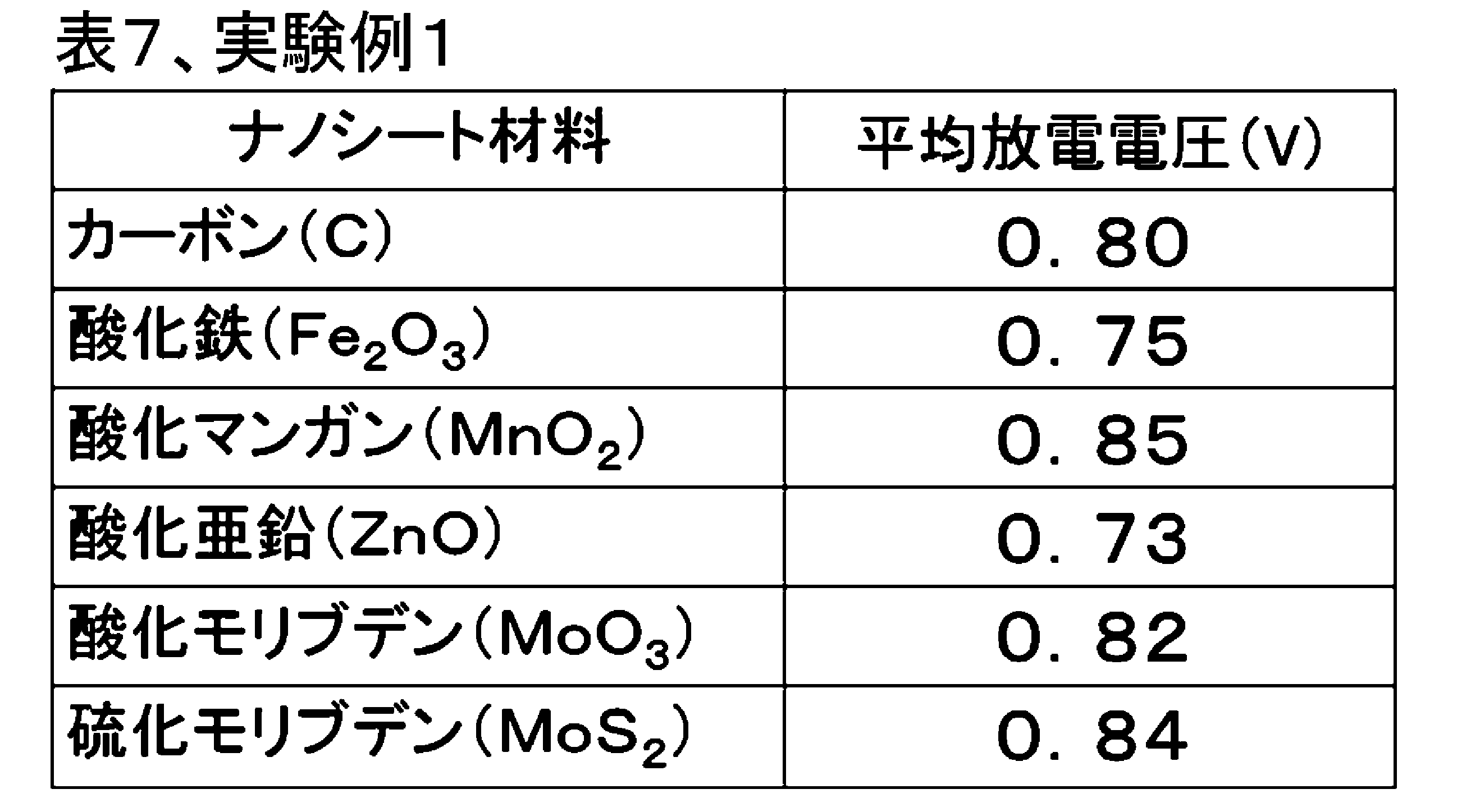
いずれも、平均放電電圧は、0.7V以上を示し、後述する粉末カーボンを用いた正極について評価した比較例1に比べて大きい値であった。炭素以外の材料によるナノシートの例の場合も、グラフェン同様、高比表面積であるため、水還元が効率的に行われたため、放電電圧が改善されたものと考えられる。
In all cases, the average discharge voltage was 0.7 V or more, which was a large value as compared with Comparative Example 1 evaluated for a positive electrode using powdered carbon described later. Also in the case of the example of the nanosheet by materials other than carbon, it is considered that the discharge voltage was improved because the water reduction was efficiently performed because of the high specific surface area as in the case of the graphene.
[実験例2]
次に、実施の形態3における実験例2について説明する。実験例2は、一体とされた複数のナノファイバーが分岐を有することで三次元ネットワーク構造とされた共連続体を正極として使用する例である。正極を、以下のようにして合成した。以下の説明では、代表として、カーボンナノファイバーを使用する製造方法を示すが、カーボンナノファイバーを他の材料によるナノファイバーに変えることで、三次元ネットワーク構造を有する共連続体を調整することができる。 [Experimental Example 2]
Next, Experimental Example 2 in the third embodiment will be described. Experimental Example 2 is an example in which a three-dimensional network structure co-continuum is used as a positive electrode by having a plurality of integrated nanofibers having a branch. The positive electrode was synthesized as follows. In the following description, a manufacturing method using carbon nanofibers is shown as a representative, but by changing the carbon nanofibers to nanofibers made of other materials, a co-continuum having a three-dimensional network structure can be prepared .
共連続体の評価法、水電池の作製、および放電試験の方法は、実験例1と同様にして行った。共連続体は、実験例1に示したプロセスと同様に作製し、原料にはカーボンナノファイバーゾル[分散媒:水(H2O)、0.4重量%、Sigma-Aldrich製]を使用した。
The evaluation method of the co-continuum, the preparation of the water battery, and the method of the discharge test were carried out in the same manner as in Experimental Example 1. The co-continuum was prepared in the same manner as the process shown in Experimental Example 1, and carbon nanofiber sol (dispersion medium: water (H 2 O), 0.4 wt%, from Sigma-Aldrich) was used as a raw material. .
得られた、共連続体は,XRD測定、SEM観察、気孔率測定、引張試験、BET比表面積測定を行い、評価した。本発明で作製した共連続体はXRD測定よりカーボン(C,PDFカードNo.00-058-1638)単相であることを確認した。また、SEM観察および水銀圧入法により、ナノファイバーが連続に連なった平均孔径が1μmの共連続体であることを確認した。また、水銀圧入法により共連続体のBET比表面積測定を測定したところ、620m2/gあった。また、水銀圧入法により共連続体の気孔率を測定したところ、93%以上であった。更に、引張試験の結果から、実験例2の共連続体は、引張応力により歪が40%加えられても、弾性領域を超えず、応力印加前の形状に復元することを確認した。
The obtained co-continuum was evaluated by performing XRD measurement, SEM observation, porosity measurement, tensile test, and BET specific surface area measurement. The co-continuum prepared in the present invention was confirmed to be carbon (C, PDF card No. 00-058-1638) single phase from XRD measurement. In addition, it was confirmed by SEM observation and a mercury intrusion method that it is a co-continuum in which the average pore diameter in which nanofibers are continuously connected is 1 μm. Moreover, it was 620 m < 2 > / g when BET specific surface area measurement of the co-continuum was measured by the mercury intrusion technique. Further, the porosity of the co-continuous body was measured by the mercury intrusion method and found to be 93% or more. Furthermore, from the results of the tensile test, it was confirmed that the co-continuum of Experimental Example 2 was restored to the shape before the stress application without exceeding the elastic region even if the strain was applied by 40% by the tensile stress.
このカーボンナノファイバーによる共連続体を正極に用いて実験例1と同様のコインセル型の水電池を作製した。作製した実験例2における水電池の放電容量を表8、表9に示す。実験例2では、放電容量は、初回で430mAh/gを示し、実験例1のグラフェンによる共連続体を用いた場合よりも大きい値であった。このような特性の向上は、より伸縮性の高い共連続体を用いることにより、放電時において円滑に反応が行われたことによると考えられる。
Using the co-continuum of carbon nanofibers as a positive electrode, a coin cell type water battery similar to that of Experimental Example 1 was produced. Tables 8 and 9 show the discharge capacity of the water battery in the experimental example 2 produced. In Experimental Example 2, the discharge capacity showed 430 mAh / g at the first time, which was a larger value than in the case of using the graphene continuum of Experimental Example 1. It is considered that such improvement of the characteristics is due to the smooth reaction at the time of discharge by using a more stretchable co-continuum.
表8には、カーボン(C)、酸化鉄(Fe2O3)、酸化マンガン(MnO2)、酸化亜鉛(ZnO)、酸化モリブデン(MoO3)、硫化モリブデン(MoS2)によるナノファイバーから共連続体を構成して正極とした水電池の平均放電電圧を示す。

Table 8 shows co-fibers from nanofibers of carbon (C), iron oxide (Fe 2 O 3 ), manganese oxide (MnO 2 ), zinc oxide (ZnO), molybdenum oxide (MoO 3 ), and molybdenum sulfide (MoS 2 ). The average discharge voltage of the water battery which comprised the continuous body and was used as the positive electrode is shown.
いずれも、平均放電電圧は、0.8V以上を示し、実験例1のようなナノシートを含む共連続体よりも全体的に大きい値であった。これらのナノファイバーの例の場合も、カーボンナノファイバー同様、伸縮性を有する正極が効率的に水還元を行ったため、放電電圧が改善されたものと考えられる。
In each case, the average discharge voltage was 0.8 V or more, which was an overall larger value than the co-continuum including the nanosheet as in Experimental Example 1. Also in the case of these examples of nanofibers, as in the case of carbon nanofibers, since the positive electrode having stretchability efficiently reduced water, it is considered that the discharge voltage was improved.
[実験例3]
次に、実験例3について説明する。実験例3では、カーボンナノファイバーによる共連続体に、酸化物または金属を触媒として担持させて構成した正極について説明する。以下では、代表として、触媒としてMnO2を共連続体に担持させる場合について説明するが、Mnを任意の金属に変えることで、任意の酸化物を触媒として共連続体に担持させることができる。また、中和の工程を行わないことで、任意の金属を触媒として共連続体に担持させることができる。 [Experimental Example 3]
Next, Experimental Example 3 will be described. In Experimental Example 3, a positive electrode formed by supporting an oxide or a metal as a catalyst on a co-continuum of carbon nanofibers will be described. Although the case where MnO 2 is supported on a co-continuous as a catalyst will be described below as a representative, any oxide can be supported on the co-continuous as a catalyst by changing Mn to an arbitrary metal. In addition, by not performing the neutralization step, it is possible to load any metal as a catalyst on the co-continuum.
共連続体の評価法、水電池の作製、充放電試験方法は、実験例1,2と同様にして行った。共連続体は、実験例2と同様に作製した。次に、市販の塩化マンガン(II)4水和物(MnCl2・4H2O;関東化学製)を蒸留水に溶解し、作製した共連続体を含浸させ、塩化マンガンを担持させた。次いで、塩化マンガンを担持する共連続体(共連続体が担持する塩化マンガン)に、徐々にアンモニア水(28%)をpH7.0になるまで滴下し、中和することで水酸化マンガンを析出させた。析出物は、塩素が残留しないように、蒸留水による洗浄を5回繰り返した。
The evaluation method of the co-continuum, the preparation of the water battery, and the charge / discharge test method were performed in the same manner as in Experimental Examples 1 and 2. The co-continuum was produced in the same manner as in Experimental Example 2. Next, commercially available manganese (II) tetrahydrate (MnCl 2 .4H 2 O; made by Kanto Chemical Co., Ltd.) was dissolved in distilled water, and the prepared co-continuum was impregnated to carry manganese chloride. Next, ammonia water (28%) is gradually added dropwise to a co-continuum supporting manganese chloride (manganese chloride supported by the co-continuum) until the pH reaches 7.0 to precipitate manganese hydroxide by neutralization. I did. The precipitate was repeatedly washed five times with distilled water so that chlorine did not remain.
得られた水酸化マンガン担持共連続体を、アルゴン雰囲気中500℃で6時間熱処理し、酸化マンガン(MnO2)を担持した共連続体を作製した。作製した酸化マンガン担持共連続体を、XRD測定、TEM観察を行い、評価した。XRD測定より、酸化マンガン(MnO2,PDFファイルNo.00-011-079)のピークを観察することができた。共連続体に担持された触媒は、酸化マンガン単相であることを確認した。また、TEMにより酸化マンガンは、共連続体の表面に平均粒径100nmの粒子状で析出している状態が観察された。
The obtained manganese hydroxide-supporting co-continuum was heat-treated at 500 ° C. for 6 hours in an argon atmosphere to prepare a co-continuum supporting manganese oxide (MnO 2 ). The produced manganese oxide-supporting cocontinuum was evaluated by performing XRD measurement and TEM observation. From the XRD measurement, it was possible to observe a peak of manganese oxide (MnO 2 , PDF file No. 00-011-079). The catalyst supported on the co-continuous was confirmed to be a manganese oxide single phase. Further, it was observed by TEM that manganese oxide was precipitated in the form of particles having an average particle diameter of 100 nm on the surface of the co-continuous body.
この酸化マンガンを担持した共連続体を正極に用いて実験例1,2と同様のコインセル型の水電池を作製した。作製した実験例3における水電池の平均放電電圧は、0.91Vであった。また、以下の表9に、他の触媒を用いた場合の結果も合わせて示す。
The coin cell type water battery similar to Experimental Examples 1 and 2 was manufactured using the co-continuum supporting the manganese oxide as a positive electrode. The average discharge voltage of the water battery in Experimental Example 3 produced was 0.91 V. Further, Table 9 below also shows the results when other catalysts are used.

実験例3では、平均放電電圧は、0.91Vとなり、実験例2の、触媒として酸化マンガンを担持していない共連続体を用いた場合よりも大きい値であった。本実験例の水電池の空気極は安定に作動することを確認した。
In Experimental Example 3, the average discharge voltage was 0.91 V, which was a value larger than that of Experimental Example 2 in the case of using a co-continuum not supporting manganese oxide as a catalyst. It was confirmed that the air electrode of the water battery of this experimental example operates stably.
[実験例4]
次に、実験例4について説明する。実験例4は、バクテリアに産生させたナノファイバーが分散したゲルによる共連続体に、更に、酸化マンガンを触媒として担持させた場合について説明する。以下では、代表として、鉄バクテリアが産生した酸化鉄によるナノファイバーから共連続体を作製した場合について示すが、鉄バクテリアを任意のバクテリアに変えることで、酸化マンガンによるナノファイバーによる共連続体を調整することができる。 [Experimental Example 4]
Next, Experimental Example 4 will be described. Experimental Example 4 describes a case where manganese oxide is further supported as a catalyst on a co-continuum of gel in which nanofibers produced by bacteria are dispersed. In the following, the case where a co-continuum is prepared from iron oxide-produced nanofibers by iron bacteria is shown as a representative, but the iron oxide is changed to any bacteria to adjust the manganese oxide-bound nanofibers can do.
共連続体の評価法、水電池の作製法、および放電試験方法は、実験例1,2と同様にして行った。
The evaluation method of the co-continuum, the manufacturing method of the water battery, and the discharge test method were performed in the same manner as in Experimental Examples 1 and 2.
まず、鉄バクテリアであるレプトスリックス・オクラセア(Leptothrix ochracea)を、鉄小片(純度99.9%以上、高純度化学研究所製)と共に試験管中のJOP液体培地に投入し、振とう器で20℃、14日間培養した。JOP液体培地は、滅菌地下水1L中、リン酸水素二ナトリウム12水和物0.076g、リン酸二水素カリウム2水和物0.02g、HEPES[4-(2-hydroxyethyl)-1-piperazineethanesulfonic acid:緩衝液用物質]2.383g、硫酸鉄0.01mmol/L、pHを水酸化ナトリウム水溶液で7.0に調整した培地である。また、レプトスリックス・オクラセアは、ATCC(American Type Culture Collection)から購入した。
First, the iron bacterium Leptothrix ochracea is placed in a JOP liquid medium in a test tube together with small pieces of iron (purity 99.9% or more, high purity chemical laboratory manufactured), and 20 shakers. C. for 14 days. JOP liquid medium: 0.076 g of disodium hydrogen phosphate dodecahydrate, 0.02 g of potassium dihydrogen phosphate dihydrate in 1 L of sterile groundwater, HEPES [4- (2-hydroxyethyl) -1-piperazineethanesulfonic acid : Buffer material] 2.383 g, 0.01 mmol / L of iron sulfate, and the medium was adjusted to pH 7.0 with aqueous sodium hydroxide solution. In addition, Leptothrix ochracea was purchased from ATCC (American Type Culture Collection).
培養した後、鉄小片を取り除き、得られたゲルを純水中で振とう器を用いて24時間洗浄を行った。この洗浄においては、純水は3度交換した。洗浄したゲルを原料とし、実験例1および実験例3に示したプロセスと同様に水電池を作製した。
After incubation, the iron fragments were removed, and the obtained gel was washed in pure water using a shaker for 24 hours. In this cleaning, pure water was exchanged three times. Using the washed gel as a raw material, a water battery was produced in the same manner as the process shown in Experimental Example 1 and Experimental Example 3.
得られた、共連続体は、XRD測定、SEM観察、気孔率測定、引張試験、BET比表面積測定を行い、評価した。本発明で作製した共連続体はXRD測定よりアモルファス状のFe3O4およびγ-Fe2O3(Fe3O4,PDFカードNo.01-075-1372,γ-Fe2O3,PDFカードNo.00-039-1346)であることを確認した。
The obtained co-continuum was evaluated by performing XRD measurement, SEM observation, porosity measurement, tensile test, and BET specific surface area measurement. The co-continuum prepared in the present invention is amorphous Fe 3 O 4 and γ-Fe 2 O 3 (Fe 3 O 4 , PDF card No. 01-075-1372, γ-Fe 2 O 3 , PDF by XRD measurement) It confirmed that it was card No. 00-039-1346).
また、SEM観察により、直径1μmで中空状のナノファイバー(ナノチューブ)が連続に連なった、共連続体であることを確認した。また、水銀圧入法により共BET比表面積測定を測定したところ、800m2/gであった。また、水銀圧入法により共連続体の気孔率を測定したところ、95%以上であった。更に、引張試験の結果から、引張応力により歪が60%加えられても、弾性領域を超えず、応力印加前の形状に復元することを確認した。
Moreover, it confirmed that it was a co-continuous body in which hollow nanofibers (nanotubes) with a diameter of 1 μm were continuously connected by SEM observation. Moreover, it was 800 m < 2 > / g when co BET specific surface area measurement was measured by the mercury intrusion technique. Moreover, it was 95% or more when the porosity of the co-continuum was measured by the mercury intrusion method. Furthermore, from the results of the tensile test, it was confirmed that even if a strain of 60% was applied by tensile stress, the shape did not exceed the elastic region and was restored to the shape before stress application.
実験例4における鉄バクテリア産生の酸化鉄ナノファイバーによる共連続体を正極に用いた水電池の、平均放電電圧は、1.00Vであった。また、以下の表10に、他の共連続体を用いた場合の結果も合わせて示す。
The average discharge voltage of the water battery using the co-continuum of iron oxide nanofibers produced by iron bacteria in Experimental Example 4 as a positive electrode was 1.00 V. In addition, Table 10 below also shows the results when other co-continuums are used.
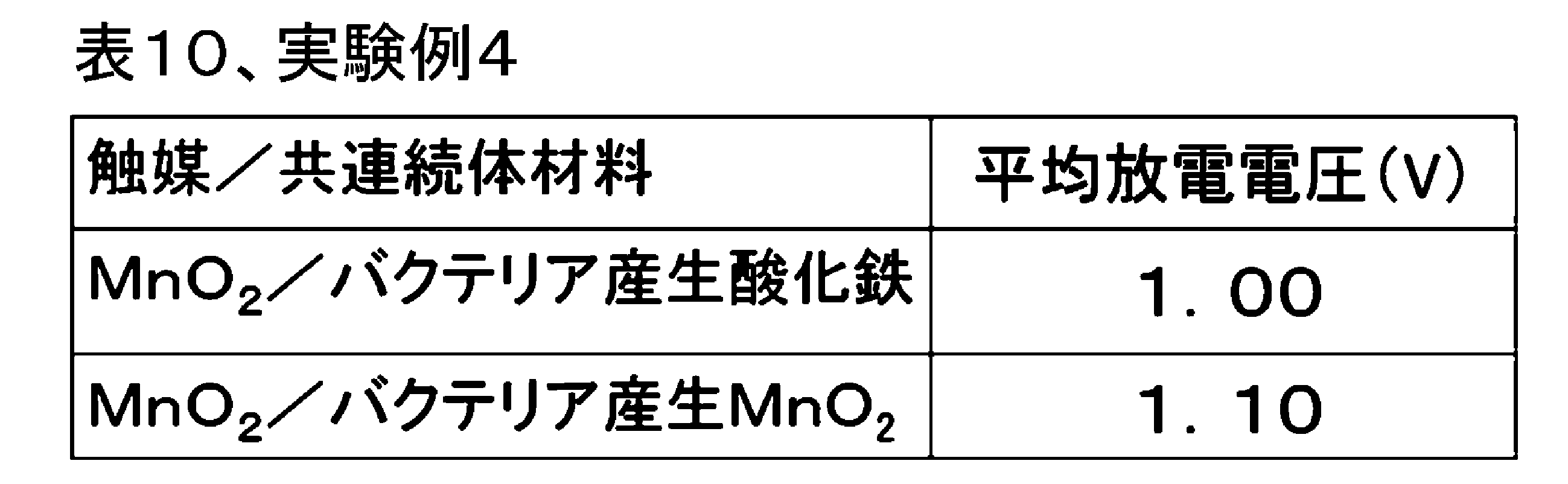
実験例4では、平均放電電圧は、1.00Vを示し、実験例3のような酸化マンガンを担持したカーボンナノファイバーによる共連続体を用いた場合よりも大きい値となった。この結果は、より触媒活性の高い共連続体を用いることにより、放電時において円滑に反応が行われたことによると考えられる。
In Experimental Example 4, the average discharge voltage was 1.00 V, which was a larger value than in the case of using a co-continuum of carbon nanofibers supporting manganese oxide as in Experimental Example 3. This result is considered to be due to the smooth reaction at the time of discharge by using the co-continuum with higher catalytic activity.
また、表10に示すように、バクテリア産生酸化マンガンによる共連続体を用い、酸化マンガンを触媒とした正極による水電池の平均放電電圧は、1.10Vを示し、実験例3よりも大きい値であった。バクテリア産生酸化マンガンは、マンガン細菌であるレプトスリックス・ディスコフォラ(Leptothrix discophora)により、マンガン小片(純度99.9%以上、高純度化学研究所製)を用いて前述同様に培養して生産した。レプトスリックス・ディスコフォラは、ATCCから購入した。このバクテリア産生ナノファイバーの場合も、鉄バクテリア産生酸化鉄同様、バクテリアにより産生された優れた伸縮性を有する正極が効率的に水還元を行ったため、放電電圧が改善されたものと考えられる。
In addition, as shown in Table 10, the average discharge voltage of the water battery by the positive electrode catalyzed by manganese oxide using the co-continuum by bacterially produced manganese oxide exhibits 1.10 V, which is larger than that of Experimental Example 3. there were. The bacterially produced manganese oxide was produced by culturing it in the same manner as described above using manganese small pieces (purity 99.9% or more, manufactured by High-Purity Chemical Laboratory) with the manganese bacterium Leptothrix discophora. Leptothrix discophora was purchased from ATCC. Also in the case of this bacterially-produced nanofiber, as in the case of iron-bacterial-produced iron oxide, the positive electrode having excellent elasticity produced by bacteria efficiently performed water reduction, and hence the discharge voltage is considered to be improved.
[実験例5]
次に、実験例5について説明する。実験例5は、バクテリアに産生させたセルロースが分散したゲルによる共連続体に、更に、酸化マンガンを触媒として担持させた場合について、共連続体の評価法、水電池の作製法、および充放電試験方法は、実験例1,2と同様にして行った。 [Experimental Example 5]
Next, Experimental Example 5 will be described. Experimental example 5 is a method of evaluating cocontinuum, method of producing water battery, and charge and discharge in the case where manganese oxide is further supported as a catalyst on cocontinuum of gel in which cellulose produced in bacteria is dispersed. The test method was carried out in the same manner as in Experimental Examples 1 and 2.
まず、酢酸菌であるアセトバクター・キシリナム(Acetobacter xylinum)産生のバクテリアセルロースゲルとして、ナタデココ(フジッコ製)を用い、実験例1および実験例3に示したプロセスと同様に水電池を作製した。なお、実験例5では、真空中で乾燥させた後、窒素雰囲気下で1200℃、2時間の焼成により、共連続体を炭化させ、これにより正極を作製した。
First, as a bacterial cellulose gel produced by Acetobacter xylinum, which is an acetic acid bacterium, Natadecoco (Fujicco) was used to prepare a water battery in the same manner as the process shown in Experimental Example 1 and Experimental Example 3. In Experimental Example 5, the co-continuum was carbonized by baking in a nitrogen atmosphere at 1200 ° C. for 2 hours after being dried in vacuum, thereby preparing a positive electrode.
得られた、共連続体(炭化した共連続体)は、XRD測定、SEM観察、気孔率測定、引張試験、BET比表面積測定を行い、評価した。この共連続体は、XRD測定よりカーボン(C,PDFカードNo.01-071-4630)単相であることを確認した。また、SEM観察により、直径20nmのナノファイバーが連続に連なった、共連続体であることを確認した。また、水銀圧入法により共連続体のBET比表面積測定を測定したところ、830m2/gであった。また、水銀圧入法により共連続体の気孔率を測定したところ、99%以上であった。更に、引張試験の結果から、引張応力により歪が80%加えられても、弾性領域を超えず、応力印加前の形状に復元することを確認し、炭化した後も優れた伸縮性を有する。
The obtained co-continuum (carbonized co-continuum) was evaluated by performing XRD measurement, SEM observation, porosity measurement, tensile test, and BET specific surface area measurement. This co-continuum was confirmed to be carbon (C, PDF card No. 01-071-4630) single phase by XRD measurement. Moreover, it confirmed that it was a co-continuous body which the nanofiber of diameter 20 nm continued in a row by SEM observation. Moreover, it was 830 m < 2 > / g when BET specific surface area measurement of the co-continuum was measured by the mercury intrusion technique. Further, the porosity of the co-continuum was measured by mercury porosimetry and was 99% or more. Furthermore, from the results of the tensile test, it is confirmed that even if strain is applied by 80% by tensile stress, it does not exceed the elastic region and restores to the shape before stress application, and has excellent stretchability even after carbonization.
実験例5における水電池の、平均放電電圧を以下の表11に示す。表11には、実験例1,2,3,4の結果も示している。実験例5では、平均放電電圧は、1.21Vを示し、実験例4のような酸化マンガンを担持した鉄バクテリア産生酸化鉄を含む共連続体を用いた場合よりも大きい値であった。
The average discharge voltage of the water battery in Experimental Example 5 is shown in Table 11 below. Table 11 also shows the results of Experimental Examples 1, 2, 3 and 4. In Experimental Example 5, the average discharge voltage was 1.21 V, which was a value larger than in the case of using a co-continuum containing iron bacteria-produced iron oxide supporting manganese oxide as in Experimental Example 4.
上記のような特性の向上は、より伸縮性の高い共連続体を用いることにより、放電時において正極が効率的に水還元を行ったことと、Cが優れた導電性を有するために、円滑に反応が行われたと考えられる。
The improvement of the characteristics as described above is smooth because the positive electrode is efficiently water-reduced at the time of discharge by using a more stretchable co-continuous body, and C has excellent conductivity. It is thought that the reaction was carried out.
上述したように、本発明により、高気孔率、BET比表面積測定で、伸縮性を有する共連続体が得られ、また、この共連続体を正極に用いた水電池によれば、放電時の効率的な水還元が実現される。上記のような特性の向上は、本発明による各種の改善が理由と考えられる。
As described above, according to the present invention, a stretchable co-continuum is obtained by high porosity and BET specific surface area measurement, and according to a water battery using this co-continuum as a positive electrode, at the time of discharge Efficient water reduction is realized. It is considered that the improvement of the characteristics as described above is due to various improvements by the present invention.
[実験例6]
次に、実験例6について説明する。実験例6は、バクテリアに産生させたセルロースが分散したゲルによる共連続体に、更に、酸化マンガンを触媒として担持させた場合について、図17を用いて説明した筐体ごと自然分解される水電池を作製した。酸化マンガンを触媒として担持させた共連続体の合成方法、共連続体の評価法、および充放電試験方法は、実験例5と同様にして行った。 [Experimental Example 6]
Next, Experimental Example 6 will be described. Experimental Example 6 is a water battery in which cellulose produced by bacteria is supported on a co-continuum of gel dispersed with manganese oxide as a catalyst, and the water battery is naturally decomposed as shown in FIG. Was produced. The synthesis method of the co-continuum on which manganese oxide was supported as a catalyst, the evaluation method of the co-continuum, and the charge / discharge test method were performed in the same manner as in Experimental Example 5.
以下、実験例6における水電池の作製方法について説明する。負極は、市販の金属マグネシウム板(厚さ200μm、ニラコ製)を、はさみを用いて20mm×20mmの正方形に切り抜くことで作製した。
Hereinafter, a method of manufacturing a water battery in Experimental Example 6 will be described. The negative electrode was produced by cutting a commercially available metal magnesium plate (200 μm thick, manufactured by Niraco) into scissors of 20 mm × 20 mm square.
電解液は、塩化カリウム(KCl、関東化学製)を1mol/Lの濃度で純水に溶解した溶液を用いた。セパレータは、電池用のセルロース系セパレータ(日本高度紙工業製)を25mm×25mmの正方形にカットして用いた。
The electrolyte used was a solution in which potassium chloride (KCl, manufactured by Kanto Chemical Co., Ltd.) was dissolved in pure water at a concentration of 1 mol / L. The separator was used by cutting a cellulose-based separator (made by Nippon High Paper Industry Co., Ltd.) for batteries into a square of 25 mm × 25 mm.
金属マグネシウム板からなる負極は、この周縁部をスポット溶接により負極集電体である銅箔(ニラコ製)に固定し、更に、この銅箔を平面視で25mm×25mmにカットし、この端を、端子となる3×20mmにカットした銅箔(ニラコ製)の短辺にスポット溶接した。
The negative electrode made of a metal magnesium plate is fixed to the copper foil (made by Niraco), which is the negative electrode current collector, by spot welding this peripheral portion, and this copper foil is further cut into 25 mm × 25 mm in plan view. It spot-welded to the short side of the copper foil (product made from Niraco) cut into 3x20 mm used as a terminal.
また、正極用の集電体としての25mm×25mmにカットした銅箔(ニラコ製)に正極を圧着し、この銅箔の端に、端子となる3×20mmにカットした銅箔(ニラコ製)の短辺にスポット溶接した。
Moreover, the positive electrode was crimped | bonded to the copper foil (made by Nyako) cut into 25 mm x 25 mm as a collector for positive electrodes, and the copper foil (made by Nyalako) cut into 3 x 20 mm used as a terminal at the end of this copper foil. Spot welded to the short side of
筐体の材料として、植物系フィルムシート エコロージュ(三菱樹脂製)を用いた。このシートを平面視30m×30mmにカットした2枚のカットシートを作製し、一方を第1筐体とし、他方を第2筐体とした。また、正極側に用いる第2筐体には、中央部にガス開放孔として2mm×2mmの開口を形成した。
A plant-based film sheet Ecologe (manufactured by Mitsubishi Plastics Co., Ltd.) was used as a material of the casing. Two cut sheets were prepared by cutting this sheet into a plan view of 30 m × 30 mm, one of which was used as a first case and the other as a second case. In the second case used for the positive electrode side, an opening of 2 mm × 2 mm was formed at the center as a gas release hole.
負極側の第1筐体の上に、負極を固定した負極集電体およびセパレータを配置し、更にセパレータには電解液を注入した。この上に、正極を圧着した正極集電体、および第2筐体を被せ、第1筐体および第2の内側の周縁部(幅約5mm)を生分解性樹脂(ミヨシ油脂製)で接着して密閉した。このようにして、水電池を作製した。
On the first housing on the negative electrode side, a negative electrode current collector on which the negative electrode was fixed and a separator were disposed, and an electrolyte was further injected into the separator. A positive electrode current collector obtained by pressure bonding the positive electrode and the second housing are placed on this, and the first housing and the second inner peripheral edge (about 5 mm in width) are bonded with a biodegradable resin (made by Miyoshi Yushi) Sealed. Thus, a water battery was produced.
実験例6における水電池の、平均放電電圧を表11に示す。表11に示すように実験例6では、平均放電電圧は、1.20Vを示し、実験例5とほぼ同様の放電電圧であった。
The average discharge voltage of the water battery in Experimental Example 6 is shown in Table 11. As shown in Table 11, in Experimental Example 6, the average discharge voltage was 1.20 V, and was substantially the same as that of Experimental Example 5.
実験例6における空気電池を放電後に土壌中に設置したところ、約半月で筐体の分解が目視で確認でき、約1カ月後には完全に消失した。土壌中の微生物によって代謝され分解されたことが示された。
When the air battery in Experimental Example 6 was installed in the soil after discharge, the decomposition of the housing was visually confirmed at about half a month, and completely disappeared after about one month. It was shown to be metabolized and degraded by microorganisms in the soil.
[実験例7]
次に、実験例7について説明する。実験例7は、実験例6と同様の手順で作製した水電池について、土壌を模擬した環境下で放電試験を行った。 [Experimental Example 7]
Next, Experimental Example 7 will be described. In Experimental Example 7, a discharge test was performed on a water battery produced by the same procedure as Experimental Example 6 in an environment simulating soil.
実験例7における水電池の、平均放電電圧を表11に示す。表11に示すように実験例7では、平均放電電圧は、1.16Vを示し、実験例6よりも低下したが、土壌環境下においても問題なく作動することが示された。また、実験例7における水電池を放電後に土壌中に放置したところ、放電試験開始時から約1カ月後には完全に消失した。
The average discharge voltage of the water battery in Experimental Example 7 is shown in Table 11. As shown in Table 11, in Experimental Example 7, the average discharge voltage was 1.16 V, which was lower than that of Experimental Example 6, but it was shown to operate without problems even in the soil environment. Further, when the water battery in Experimental Example 7 was left in the soil after discharge, it completely disappeared about one month after the start of the discharge test.
[比較例1]
次に、比較例1について説明する。比較例1は、一般的な空気電池の空気極用の電極として公知であるカーボン(ケッチェンブラックEC600JD)、および酸化マンガンを用いた水電池セルを作製して評価した。比較例1では、実験例1と同様のコインセル型の水電池を作製した。 Comparative Example 1
Next, Comparative Example 1 will be described. The comparative example 1 produced and evaluated the water battery cell using well-known carbon as an electrode for air electrodes of a general air battery (Ketjen black EC600JD), and manganese oxide. In Comparative Example 1, a coin cell type water battery similar to that of Experimental Example 1 was produced.
酸化マンガン粉末(関東化学製)、ケッチェンブラック粉末(ライオン製)およびポリテトラフルオロエチレン(PTFE)粉末(ダイキン製)を50:30:20の重量比で、らいかい機を用いて十分に粉砕および混合し、ロール成形して、シート状電極(厚さ:0.5mm)を作製した。このシート状電極を直径14mmの円形に切り抜き正極を得た。電池の放電試験の条件は、実験例1と同様である。
Manganese oxide powder (Kanto Chemical), ketjen black powder (Lion), and polytetrafluoroethylene (PTFE) powder (Daikin) at a weight ratio of 50:30:20, sufficiently ground using a grinder. And it mixed and roll-formed and produced sheet-like electrode (thickness: 0.5 mm). The sheet electrode was cut into a circle having a diameter of 14 mm to obtain a positive electrode. The conditions of the discharge test of the battery are the same as in Experimental Example 1.
比較例1に係る水電池の平均放電電圧を実験例1~7の結果とともに表11に示す。表11に示すように、比較例1の平均放電電圧は、0.50Vであり、実験例1よりも小さな値を示した。また、測定後に比較例1の正極を観察したところ、正極の一部が崩れて電解液中に分散しており、正極の電極構造が破壊されている様子が見られた。
The average discharge voltage of the water battery according to Comparative Example 1 is shown in Table 11 together with the results of Experimental Examples 1 to 7. As shown in Table 11, the average discharge voltage of Comparative Example 1 was 0.50 V, which was smaller than that of Experimental Example 1. Moreover, when the positive electrode of Comparative Example 1 was observed after the measurement, a part of the positive electrode was broken and dispersed in the electrolytic solution, and it was observed that the electrode structure of the positive electrode was broken.
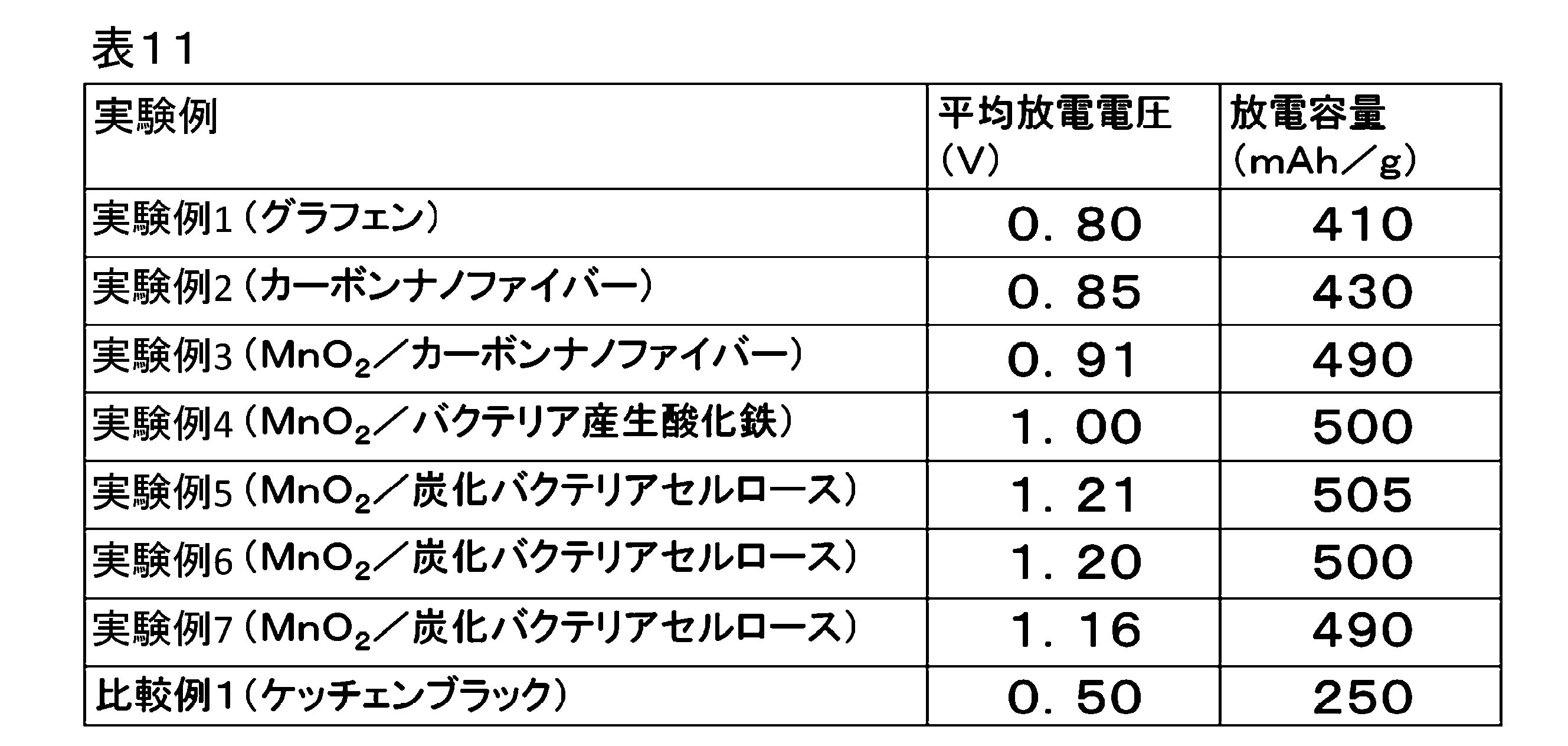
次に、実施の形態3における各実験例1~7,および比較例1について、負極をFeから構成した場合、負極を亜鉛から構成した場合、および負極をAlから構成した場合の同様の結果について、以下の表12に示す。
Next, for each of Experimental Examples 1 to 7 and Comparative Example 1 in the third embodiment, when the negative electrode is made of Fe, when the negative electrode is made of zinc, and when the negative electrode is made of Al Table 12 below.
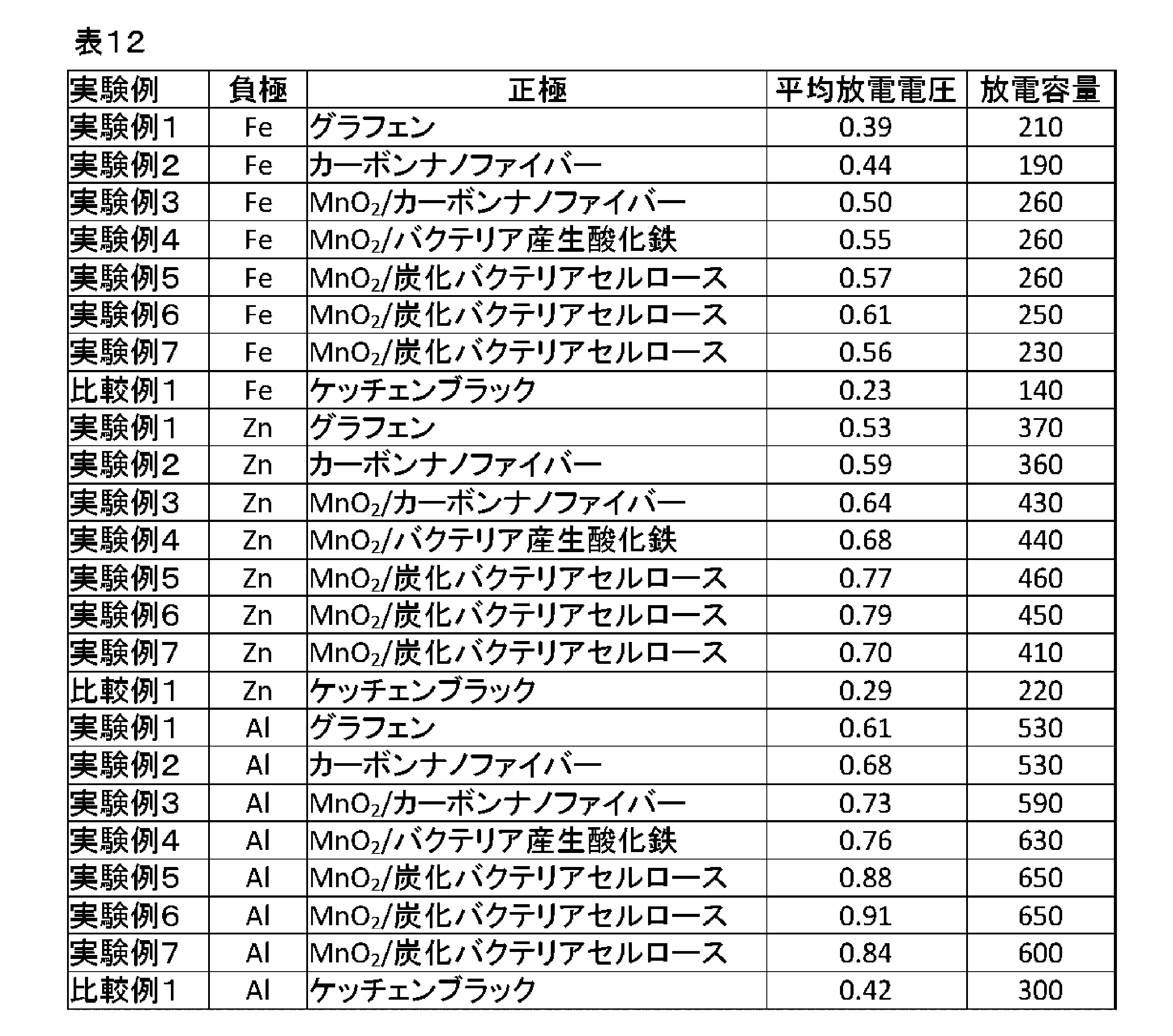
以上の結果より、実施の形態3における電池(水電池)は、公知の材料による正極を用いた水電池よりも、電圧および容量に関して優れていることが確認された。
From the above results, it was confirmed that the battery (water battery) in the third embodiment is superior in terms of voltage and capacity to a water battery using a positive electrode made of a known material.
以上に説明したように、実施の形態3によれば、一体とされた複数のナノ構造体が分岐を有することで三次元ネットワーク構造とされた共連続体から正極を構成したので、マグネシウムを負極に用いた電池(水電池)がより容易に取り扱えるようになる。本発明の電池は、土壌の肥料に用いられる元素や雨水や海水中に含まれる金属以外の金属元素が含まれず、また、自然分解されるため、極めて環境負荷が低い。このような電池は、日常環境の使い捨て電池を始め、土壌中で用いるセンサーなどの様々な駆動源として有効利用することができる。また、本発明によれば、水電池の放電電圧を大きくすることができる。
As described above, according to the third embodiment, since a plurality of integrated nanostructures have a branch, the positive electrode is formed from a co-continuous body formed into a three-dimensional network structure, so magnesium is used as the negative electrode. The battery used in (water battery) can be handled more easily. The battery of the present invention does not contain an element used for soil fertilizer or a metal element other than metals contained in rainwater and seawater, and is naturally decomposed, so the environmental load is extremely low. Such a battery can be effectively utilized as a disposable battery in a daily environment and various driving sources such as a sensor used in the soil. Further, according to the present invention, the discharge voltage of the water battery can be increased.
なお、本発明は以上に説明した実施の形態に限定されるものではなく、本発明の技術的思想内で、当分野において通常の知識を有する者により、多くの変形および組み合わせが実施可能であることは明白である。
The present invention is not limited to the embodiments described above, and many modifications and combinations can be made by those skilled in the art within the technical concept of the present invention. It is clear.
101…正極、102…負極、103…電解質。
101: positive electrode, 102: negative electrode, 103: electrolyte.
Claims (14)
- 複数のナノ構造体から構成された三次元ネットワーク構造の共連続体から構成された正極と、
負極と、
前記正極と前記負極とに挾まれて配置されて塩から構成された電解質と
を備えることを特徴とする電池。 A positive electrode composed of a co-continuum of a three-dimensional network structure composed of a plurality of nanostructures,
A negative electrode,
A battery comprising: an electrolyte which is disposed between the positive electrode and the negative electrode and is made of a salt. - 請求項1記載の電池において、
前記複数のナノ構造体の各々は、
カーボン、酸化鉄、酸化マンガン、酸化亜鉛、酸化モリブデン、硫化モリブデンの少なくとも1つから構成されたナノシート、
または、
カーボン、酸化鉄、酸化マンガン、酸化亜鉛、酸化モリブデン、硫化モリブデン、およびセルロースの少なくとも1つから構成されたナノファイバー
であることを特徴とする電池。 In the battery according to claim 1,
Each of the plurality of nanostructures is
Nanosheets composed of at least one of carbon, iron oxide, manganese oxide, zinc oxide, molybdenum oxide, molybdenum sulfide,
Or
What is claimed is: 1. A battery comprising: a nanofiber comprising at least one of carbon, iron oxide, manganese oxide, zinc oxide, molybdenum oxide, molybdenum sulfide, and cellulose. - 請求項1記載の電池において、
前記正極に担持された触媒を更に備え、
前記触媒は、鉄、マンガン、亜鉛、銅、モリブデンの少なくとも1つの金属、またはカルシウム、鉄、マンガン、亜鉛、銅、モリブデンの少なくとも1つの金属の酸化物から構成されている
ことを特徴とする電池。 In the battery according to claim 1,
The catalyst further comprises a catalyst supported on the positive electrode,
The battery is characterized in that the catalyst comprises an oxide of at least one metal of iron, manganese, zinc, copper, molybdenum, or at least one metal of calcium, iron, manganese, zinc, copper, molybdenum. . - 請求項1記載の電池において、
前記電解質は、塩化カリウムおよび塩化ナトリウムのいずれかまたはこれらの混合物の水溶液から構成されていることを特徴とする電池。 In the battery according to claim 1,
The battery is characterized in that the electrolyte is an aqueous solution of either potassium chloride and sodium chloride or a mixture thereof. - 請求項1記載の電池において、
前記正極、前記電解質、および前記負極を含むセルを収容する筐体を備え、
前記筐体は自然分解される材料から構成されていることを特徴とする電池。 In the battery according to claim 1,
A housing for housing a cell including the positive electrode, the electrolyte, and the negative electrode;
The battery is characterized in that the housing is made of a material that is naturally decomposed. - 請求項1記載の電池において、
前記負極は、マグネシウム、亜鉛、鉄、アルミニウムのいずれかを含むことを特徴とする電池。 In the battery according to claim 1,
The said negative electrode contains magnesium, zinc, iron, or any one of aluminum. - 請求項1~6のいずれか1項に記載の電池において、
前記正極は、空気極であることを特徴とする電池。 The battery according to any one of claims 1 to 6.
The battery is characterized in that the positive electrode is an air electrode. - 請求項1~6のいずれか1項に記載の電池において、
前記正極における活性物質は、水であることを特徴とする電池。 The battery according to any one of claims 1 to 6.
An active material in the positive electrode is water. - 複数のナノ構造体から構成された三次元ネットワーク構造の共連続体から構成された正極と、負極と、前記正極と前記負極とに挾まれて配置されて塩から構成された電解質とを備える電池の前記正極の製造方法であって、
前記複数のナノ構造体が分散したゾルまたはゲルを凍結させて凍結体を得る凍結工程と、
前記凍結体を真空中で乾燥させて前記共連続体を得る乾燥工程と
を備えることを特徴とする電池の正極の製造方法。 A battery comprising: a positive electrode composed of a co-continuum of a three-dimensional network structure composed of a plurality of nanostructures, a negative electrode, and an electrolyte composed of a salt and disposed between the positive electrode and the negative electrode A method of manufacturing the positive electrode of
Freezing the sol or gel in which the plurality of nanostructures are dispersed to obtain a frozen body;
Drying the frozen body in a vacuum to obtain the co-continuum. - 請求項9記載の電池の正極の製造方法において、
バクテリアに、酸化鉄、酸化マンガン、セルロースのいずれかによって構成されたナノファイバーが分散した前記ゲルを生産させるゲル生産工程を備え、
前記凍結工程は、前記ゲル生産工程で生産した前記ゲルを凍結させて前記凍結体を得ることを特徴とする電池の正極の製造方法。 In the method of manufacturing a positive electrode of a battery according to claim 9,
And a gel production step of causing bacteria to produce the gel in which nanofibers composed of any of iron oxide, manganese oxide and cellulose are dispersed,
The method for producing a positive electrode of a battery, wherein the freezing step is a step of freezing the gel produced in the gel production step to obtain the frozen body. - 請求項10記載の電池の正極の製造方法において、
前記ゲルより得られる前記共連続体をセルロースが燃焼しないガスの雰囲気で加熱して炭化する炭化工程を更に備え、
前記ゲル生産工程は、セルロースによって構成された前記ナノファイバーが分散した前記ゲルを生産することを特徴とする電池の正極の製造方法。 In the method of manufacturing a positive electrode of a battery according to claim 10,
The method further comprises a carbonizing step of heating and carbonizing the co-continuum obtained from the gel in a gas atmosphere in which cellulose does not burn,
The method for producing a positive electrode of a battery, wherein the gel production step produces the gel in which the nanofibers composed of cellulose are dispersed. - 請求項9記載の電池の正極の製造方法において、
前記負極は、マグネシウム、亜鉛、鉄、アルミニウムのいずれかを含むことを特徴とする電池の正極の製造方法。 In the method of manufacturing a positive electrode of a battery according to claim 9,
The method for manufacturing a positive electrode of a battery, wherein the negative electrode contains any of magnesium, zinc, iron, and aluminum. - 請求項9~12のいずれか1項に記載の電池の正極の製造方法において、
前記正極は、空気極であることを特徴とする電池の正極の製造方法。 A method of manufacturing a positive electrode of a battery according to any one of claims 9 to 12,
The method for manufacturing a positive electrode of a battery, wherein the positive electrode is an air electrode. - 請求項9~12のいずれか1項に記載の電池の正極の製造方法において、
前記正極における活性物質は、水であることを特徴とする電池の正極の製造方法。 A method of manufacturing a positive electrode of a battery according to any one of claims 9 to 12,
The active material in the said positive electrode is water, The manufacturing method of the positive electrode of the battery characterized by the above-mentioned.
Priority Applications (4)
| Application Number | Priority Date | Filing Date | Title |
|---|---|---|---|
| JP2018525147A JP6711915B2 (en) | 2016-07-01 | 2017-06-26 | Battery and method for manufacturing positive electrode thereof |
| EP17820080.4A EP3518338B1 (en) | 2016-07-01 | 2017-06-26 | Battery and method for producing positive electrode for same |
| CN201780041139.2A CN109417209A (en) | 2016-07-01 | 2017-06-26 | Battery and the method for manufacturing its anode |
| US16/312,188 US11876207B2 (en) | 2016-07-01 | 2017-06-26 | Battery and method of manufacturing cathode of the same |
Applications Claiming Priority (6)
| Application Number | Priority Date | Filing Date | Title |
|---|---|---|---|
| JP2016-131441 | 2016-07-01 | ||
| JP2016131439 | 2016-07-01 | ||
| JP2016-131439 | 2016-07-01 | ||
| JP2016131441 | 2016-07-01 | ||
| JP2016244113 | 2016-12-16 | ||
| JP2016-244113 | 2016-12-16 |
Publications (1)
| Publication Number | Publication Date |
|---|---|
| WO2018003724A1 true WO2018003724A1 (en) | 2018-01-04 |
Family
ID=60787317
Family Applications (1)
| Application Number | Title | Priority Date | Filing Date |
|---|---|---|---|
| PCT/JP2017/023338 WO2018003724A1 (en) | 2016-07-01 | 2017-06-26 | Battery and method for producing positive electrode for same |
Country Status (5)
| Country | Link |
|---|---|
| US (1) | US11876207B2 (en) |
| EP (1) | EP3518338B1 (en) |
| JP (1) | JP6711915B2 (en) |
| CN (1) | CN109417209A (en) |
| WO (1) | WO2018003724A1 (en) |
Cited By (6)
| Publication number | Priority date | Publication date | Assignee | Title |
|---|---|---|---|---|
| JP2020102398A (en) * | 2018-12-25 | 2020-07-02 | 日本電信電話株式会社 | Bipolar metal-air battery, manufacturing method of air electrode, and manufacturing method of collector |
| US11089633B2 (en) | 2017-09-08 | 2021-08-10 | Samsung Electronics Co., Ltd. | Method and apparatus for resource determination, resource configuration, transmitting random access preamble and random access |
| WO2022070393A1 (en) * | 2020-10-01 | 2022-04-07 | 日本電信電話株式会社 | Metal-air battery |
| WO2022097200A1 (en) * | 2020-11-04 | 2022-05-12 | 日本電信電話株式会社 | Metal-air battery and method for producing air electrode |
| KR20220090068A (en) * | 2020-12-22 | 2022-06-29 | 울산과학기술원 | MANUFACTURING METHOD FOR MOLYBDEN DISUlFIDE CATALYST ELECTRODE FOR SEAWATER BATTERY AND MOLYBDEN DISUlFIDE CATALYST ELECTRODE |
| US11855271B2 (en) | 2019-12-03 | 2023-12-26 | Nippon Telegraph And Telephone Corporation | Metal air battery, cathode manufacturing method of metal air battery and manufacturing method of metal air battery |
Families Citing this family (2)
| Publication number | Priority date | Publication date | Assignee | Title |
|---|---|---|---|---|
| CN110233314A (en) * | 2019-06-28 | 2019-09-13 | 江苏大学 | Double electrolyte aluminium-air cells |
| WO2021111495A1 (en) * | 2019-12-02 | 2021-06-10 | 日本電信電話株式会社 | Air battery, and method for producing positive electrode of air battery |
Citations (10)
| Publication number | Priority date | Publication date | Assignee | Title |
|---|---|---|---|---|
| JP2001155694A (en) * | 1999-11-26 | 2001-06-08 | Toshiba Battery Co Ltd | Cell |
| JP2003272673A (en) * | 2002-03-20 | 2003-09-26 | Toyota Motor Corp | Power source device for vehicle |
| JP2006001751A (en) * | 2004-06-15 | 2006-01-05 | Matsushita Electric Ind Co Ltd | Transition metal oxide nanostructure body having cotton-like structure, and its production method |
| WO2011074122A1 (en) * | 2009-12-18 | 2011-06-23 | トヨタ自動車株式会社 | Air electrode for use in air battery, and air battery comprising air electrode |
| JP2012502427A (en) * | 2008-09-08 | 2012-01-26 | ナンヤン テクノロジカル ユニヴァーシティー | Electrode materials for metal-air batteries, fuel cells and supercapacitors |
| JP2015026482A (en) * | 2013-07-25 | 2015-02-05 | 国立大学法人北海道大学 | Porous carbon material and process of manufacturing the same |
| JP2015046312A (en) * | 2013-08-28 | 2015-03-12 | 古河電池株式会社 | Magnesium battery |
| JP2015046368A (en) * | 2013-08-29 | 2015-03-12 | 古河電池株式会社 | Magnesium battery |
| JP2015195194A (en) * | 2014-03-28 | 2015-11-05 | 国立大学法人 大分大学 | Oxygen electrode catalyst and manufacturing method for the same |
| JP2016004693A (en) * | 2014-06-17 | 2016-01-12 | 充 吉川 | Magnesium air battery |
Family Cites Families (17)
| Publication number | Priority date | Publication date | Assignee | Title |
|---|---|---|---|---|
| JP2821456B1 (en) | 1997-07-03 | 1998-11-05 | 学校法人早稲田大学 | Cobalt / iron / nickel magnetic thin film and manufacturing method thereof, and composite thin film magnetic head and magnetic storage device using the same |
| US20050025970A1 (en) * | 2002-12-06 | 2005-02-03 | Bozidar Stipanovic | Carbon beads |
| JP5162817B2 (en) | 2005-08-26 | 2013-03-13 | 宇部興産株式会社 | Network carbon material |
| CN101811689A (en) * | 2009-02-23 | 2010-08-25 | 西南科技大学 | Three-dimensional network carbon nanofiber and preparation method and application thereof |
| KR20120114383A (en) * | 2010-01-29 | 2012-10-16 | 에버레디 배터리 컴퍼니, 인크. | Method of making an electrochemical cell with a catalytic electrode including manganese dioxide |
| CN101941693B (en) * | 2010-08-25 | 2012-07-25 | 北京理工大学 | Graphene aerogel and preparation method thereof |
| GB201100712D0 (en) * | 2011-01-17 | 2011-03-02 | Bio Nano Consulting | Cross-linked carbon nanotube networks |
| US10319537B2 (en) * | 2011-08-15 | 2019-06-11 | Purdue Research Foundation | Modified graphitic electrodes for electrochemical energy storage enhancement |
| JP2013149530A (en) * | 2012-01-20 | 2013-08-01 | Mishimadenshi Co Ltd | Water feeding device for water cell and water cell including the same |
| JP6037498B2 (en) * | 2012-04-13 | 2016-12-07 | 国立大学法人山梨大学 | Method for producing metal oxide-carrying carbon paper and metal oxide-carrying carbon paper |
| CN103285920B (en) * | 2013-05-27 | 2015-04-08 | 东华大学 | Three-dimensional fiber-based aerogel catalyst carrier and preparation method thereof |
| CN103337639B (en) | 2013-06-24 | 2015-05-13 | 太原理工大学 | Preparation method of carbon nano tube array/carbon fiber fabric integrated three-dimensional porous air electrode |
| CN104600319B (en) * | 2013-10-31 | 2018-06-22 | 中国科学院上海硅酸盐研究所 | Non-carbon lithium-air electrode |
| WO2015109272A1 (en) | 2014-01-17 | 2015-07-23 | The Trustees Of Dartmouth College | Material and method of manufacture of electrodes and porous filters formed of ice-templated graphene-oxide and carbon nanotube composite, and applications thereof |
| CN104201397B (en) | 2014-08-20 | 2016-06-15 | 中南大学 | The preparation method of a kind of lithium-air battery electrode |
| CN104733700B (en) * | 2015-02-04 | 2017-05-10 | 中南大学 | Preparation method of flexible anode of lithium-selenium battery |
| CN105449226A (en) | 2015-11-18 | 2016-03-30 | 广西师范大学 | Novel three-dimensional electrode material for lithium air battery and preparation method for novel three-dimensional electrode material |
-
2017
- 2017-06-26 EP EP17820080.4A patent/EP3518338B1/en active Active
- 2017-06-26 CN CN201780041139.2A patent/CN109417209A/en active Pending
- 2017-06-26 JP JP2018525147A patent/JP6711915B2/en active Active
- 2017-06-26 US US16/312,188 patent/US11876207B2/en active Active
- 2017-06-26 WO PCT/JP2017/023338 patent/WO2018003724A1/en unknown
Patent Citations (10)
| Publication number | Priority date | Publication date | Assignee | Title |
|---|---|---|---|---|
| JP2001155694A (en) * | 1999-11-26 | 2001-06-08 | Toshiba Battery Co Ltd | Cell |
| JP2003272673A (en) * | 2002-03-20 | 2003-09-26 | Toyota Motor Corp | Power source device for vehicle |
| JP2006001751A (en) * | 2004-06-15 | 2006-01-05 | Matsushita Electric Ind Co Ltd | Transition metal oxide nanostructure body having cotton-like structure, and its production method |
| JP2012502427A (en) * | 2008-09-08 | 2012-01-26 | ナンヤン テクノロジカル ユニヴァーシティー | Electrode materials for metal-air batteries, fuel cells and supercapacitors |
| WO2011074122A1 (en) * | 2009-12-18 | 2011-06-23 | トヨタ自動車株式会社 | Air electrode for use in air battery, and air battery comprising air electrode |
| JP2015026482A (en) * | 2013-07-25 | 2015-02-05 | 国立大学法人北海道大学 | Porous carbon material and process of manufacturing the same |
| JP2015046312A (en) * | 2013-08-28 | 2015-03-12 | 古河電池株式会社 | Magnesium battery |
| JP2015046368A (en) * | 2013-08-29 | 2015-03-12 | 古河電池株式会社 | Magnesium battery |
| JP2015195194A (en) * | 2014-03-28 | 2015-11-05 | 国立大学法人 大分大学 | Oxygen electrode catalyst and manufacturing method for the same |
| JP2016004693A (en) * | 2014-06-17 | 2016-01-12 | 充 吉川 | Magnesium air battery |
Non-Patent Citations (1)
| Title |
|---|
| See also references of EP3518338A4 * |
Cited By (9)
| Publication number | Priority date | Publication date | Assignee | Title |
|---|---|---|---|---|
| US11089633B2 (en) | 2017-09-08 | 2021-08-10 | Samsung Electronics Co., Ltd. | Method and apparatus for resource determination, resource configuration, transmitting random access preamble and random access |
| JP2020102398A (en) * | 2018-12-25 | 2020-07-02 | 日本電信電話株式会社 | Bipolar metal-air battery, manufacturing method of air electrode, and manufacturing method of collector |
| WO2020137546A1 (en) * | 2018-12-25 | 2020-07-02 | 日本電信電話株式会社 | Bipolar metal-air battery, air electrode manufacturing method, and collector manufacturing method |
| JP7068585B2 (en) | 2018-12-25 | 2022-05-17 | 日本電信電話株式会社 | Bipolar metal-air battery, air electrode manufacturing method, and current collector manufacturing method |
| US11855271B2 (en) | 2019-12-03 | 2023-12-26 | Nippon Telegraph And Telephone Corporation | Metal air battery, cathode manufacturing method of metal air battery and manufacturing method of metal air battery |
| WO2022070393A1 (en) * | 2020-10-01 | 2022-04-07 | 日本電信電話株式会社 | Metal-air battery |
| WO2022097200A1 (en) * | 2020-11-04 | 2022-05-12 | 日本電信電話株式会社 | Metal-air battery and method for producing air electrode |
| KR20220090068A (en) * | 2020-12-22 | 2022-06-29 | 울산과학기술원 | MANUFACTURING METHOD FOR MOLYBDEN DISUlFIDE CATALYST ELECTRODE FOR SEAWATER BATTERY AND MOLYBDEN DISUlFIDE CATALYST ELECTRODE |
| KR102548276B1 (en) | 2020-12-22 | 2023-06-28 | 울산과학기술원 | MANUFACTURING METHOD FOR MOLYBDEN DISUlFIDE CATALYST ELECTRODE FOR SEAWATER BATTERY AND MOLYBDEN DISUlFIDE CATALYST ELECTRODE |
Also Published As
| Publication number | Publication date |
|---|---|
| EP3518338B1 (en) | 2023-08-09 |
| CN109417209A (en) | 2019-03-01 |
| JPWO2018003724A1 (en) | 2018-10-11 |
| EP3518338A1 (en) | 2019-07-31 |
| US20190237834A1 (en) | 2019-08-01 |
| JP6711915B2 (en) | 2020-06-17 |
| EP3518338A4 (en) | 2020-06-24 |
| US11876207B2 (en) | 2024-01-16 |
Similar Documents
| Publication | Publication Date | Title |
|---|---|---|
| JP6711915B2 (en) | Battery and method for manufacturing positive electrode thereof | |
| JP6951623B2 (en) | Manufacturing method of magnesium water battery and its positive electrode | |
| Miot et al. | Biomineralized α-Fe 2 O 3: texture and electrochemical reaction with Li | |
| WO2019220999A1 (en) | Metal-air battery and method of producing air electrode | |
| JP6695304B2 (en) | Method for manufacturing magnesium-air battery, positive electrode thereof, negative electrode and separator | |
| JP6563804B2 (en) | Air electrode for lithium air secondary battery, method for producing the same, and lithium air secondary battery | |
| WO2020137557A1 (en) | Metal-air battery and production method for air electrode | |
| JP6715173B2 (en) | Zinc-air battery manufacturing method | |
| JP6673759B2 (en) | Manufacturing method of magnesium air battery | |
| JP7356053B2 (en) | Air battery and method for manufacturing air battery | |
| JP7464857B2 (en) | Metal-air battery and method for manufacturing the metal-air battery | |
| JP7068585B2 (en) | Bipolar metal-air battery, air electrode manufacturing method, and current collector manufacturing method | |
| WO2022091267A1 (en) | Metal-air battery | |
| WO2022070393A1 (en) | Metal-air battery | |
| JP7469700B2 (en) | METAL-AIR BATTERY AND METHOD FOR MANUFACTURING AIR ELECTRODE | |
| WO2022097200A1 (en) | Metal-air battery and method for producing air electrode | |
| KR102427234B1 (en) | Defective holey nanocomposite |
Legal Events
| Date | Code | Title | Description |
|---|---|---|---|
| ENP | Entry into the national phase |
Ref document number: 2018525147 Country of ref document: JP Kind code of ref document: A |
|
| 121 | Ep: the epo has been informed by wipo that ep was designated in this application |
Ref document number: 17820080 Country of ref document: EP Kind code of ref document: A1 |
|
| NENP | Non-entry into the national phase |
Ref country code: DE |
|
| ENP | Entry into the national phase |
Ref document number: 2017820080 Country of ref document: EP Effective date: 20190201 |