WO2018002972A1 - 絶縁構造製造方法、絶縁構造および回転電機 - Google Patents
絶縁構造製造方法、絶縁構造および回転電機 Download PDFInfo
- Publication number
- WO2018002972A1 WO2018002972A1 PCT/JP2016/003164 JP2016003164W WO2018002972A1 WO 2018002972 A1 WO2018002972 A1 WO 2018002972A1 JP 2016003164 W JP2016003164 W JP 2016003164W WO 2018002972 A1 WO2018002972 A1 WO 2018002972A1
- Authority
- WO
- WIPO (PCT)
- Prior art keywords
- polymer
- insulating
- nanoparticles
- main insulating
- main
- Prior art date
Links
Images


Classifications
-
- H—ELECTRICITY
- H01—ELECTRIC ELEMENTS
- H01B—CABLES; CONDUCTORS; INSULATORS; SELECTION OF MATERIALS FOR THEIR CONDUCTIVE, INSULATING OR DIELECTRIC PROPERTIES
- H01B13/00—Apparatus or processes specially adapted for manufacturing conductors or cables
-
- H—ELECTRICITY
- H01—ELECTRIC ELEMENTS
- H01B—CABLES; CONDUCTORS; INSULATORS; SELECTION OF MATERIALS FOR THEIR CONDUCTIVE, INSULATING OR DIELECTRIC PROPERTIES
- H01B17/00—Insulators or insulating bodies characterised by their form
- H01B17/56—Insulating bodies
- H01B17/62—Insulating-layers or insulating-films on metal bodies
-
- H—ELECTRICITY
- H01—ELECTRIC ELEMENTS
- H01B—CABLES; CONDUCTORS; INSULATORS; SELECTION OF MATERIALS FOR THEIR CONDUCTIVE, INSULATING OR DIELECTRIC PROPERTIES
- H01B19/00—Apparatus or processes specially adapted for manufacturing insulators or insulating bodies
- H01B19/02—Drying; Impregnating
-
- H—ELECTRICITY
- H01—ELECTRIC ELEMENTS
- H01B—CABLES; CONDUCTORS; INSULATORS; SELECTION OF MATERIALS FOR THEIR CONDUCTIVE, INSULATING OR DIELECTRIC PROPERTIES
- H01B19/00—Apparatus or processes specially adapted for manufacturing insulators or insulating bodies
- H01B19/04—Treating the surfaces, e.g. applying coatings
-
- H—ELECTRICITY
- H02—GENERATION; CONVERSION OR DISTRIBUTION OF ELECTRIC POWER
- H02K—DYNAMO-ELECTRIC MACHINES
- H02K15/00—Methods or apparatus specially adapted for manufacturing, assembling, maintaining or repairing of dynamo-electric machines
- H02K15/10—Applying solid insulation to windings, stators or rotors
- H02K15/105—Applying solid insulation to windings, stators or rotors to the windings
-
- H—ELECTRICITY
- H02—GENERATION; CONVERSION OR DISTRIBUTION OF ELECTRIC POWER
- H02K—DYNAMO-ELECTRIC MACHINES
- H02K15/00—Methods or apparatus specially adapted for manufacturing, assembling, maintaining or repairing of dynamo-electric machines
- H02K15/12—Impregnating, heating or drying of windings, stators, rotors or machines
-
- H—ELECTRICITY
- H02—GENERATION; CONVERSION OR DISTRIBUTION OF ELECTRIC POWER
- H02K—DYNAMO-ELECTRIC MACHINES
- H02K3/00—Details of windings
- H02K3/30—Windings characterised by the insulating material
-
- H—ELECTRICITY
- H02—GENERATION; CONVERSION OR DISTRIBUTION OF ELECTRIC POWER
- H02K—DYNAMO-ELECTRIC MACHINES
- H02K3/00—Details of windings
- H02K3/32—Windings characterised by the shape, form or construction of the insulation
- H02K3/40—Windings characterised by the shape, form or construction of the insulation for high voltage, e.g. affording protection against corona discharges
-
- H—ELECTRICITY
- H02—GENERATION; CONVERSION OR DISTRIBUTION OF ELECTRIC POWER
- H02K—DYNAMO-ELECTRIC MACHINES
- H02K7/00—Arrangements for handling mechanical energy structurally associated with dynamo-electric machines, e.g. structural association with mechanical driving motors or auxiliary dynamo-electric machines
- H02K7/08—Structural association with bearings
- H02K7/083—Structural association with bearings radially supporting the rotary shaft at both ends of the rotor
Definitions
- the present invention relates to an insulating structure manufacturing method, an insulating structure, and a rotating electric machine using the same.
- the electrical tree is considered to start from a high electric field concentration part such as an air gap between the electrode and the insulator, foreign matter, foreign matter, protrusion, void in the insulator.
- inverter-driven electric motors In recent years, the use of inverters has progressed, but in inverter-driven electric motors, repeated use of an impulse voltage including inverter surges can significantly reduce the life of the insulation material of the coil conductors. . For this reason, for example, the inverter drive motor for the rated voltage of 3.3 kV has a situation in which it is inevitably required to use the insulation for the normal rated voltage of 6.6 kV.
- a coil lead wire is usually covered with an insulator having an insulating material.
- a conductor that reaches a relatively high temperature often has a mica insulation structure using mica (mica), which is a kind of silicate mineral, as an insulation material having a high insulation class that can withstand a relatively high temperature.
- a mica insulating structure is frequently used.
- the mica insulation structure as the main insulation is often formed by impregnating mica insulation tape with epoxy resin.
- the mica insulating tape is composed of mica and an epoxy glass layer.
- the mica insulating tape thus configured is wound around a coil conductor and then impregnated with an epoxy resin, whereby an insulating process using a mica insulating structure is performed.
- the present invention has been made on the basis of such knowledge, and an object thereof is to suppress the progress of an electrical tree in an insulating structure.
- the present invention is a method for manufacturing an insulating structure that covers the outer surface of an object to be insulated, and includes a sheet manufacturing step for manufacturing a main insulating sheet in which nanoparticles are mixed, and the main insulating sheet.
- a cutting step for cutting into a main insulating tape, a taping step for generating a post-taping insulating object formed by taping outside the object to be insulated with the main insulating tape to form a main insulating part, and the insulation after the taping step An evacuation step for evacuating an object; an impregnation step after the evacuation step for impregnating the insulating portion formed on the insulation object after taping with an impregnating polymer; and impregnation And after the step, the insulating portion is heated to solidify the polymer containing the nanoparticles, and the solidifying step. That.
- the present invention is an insulating structure that covers the outer surface of the object to be insulated so as to cover the outer surface of the object and electrically insulate the object, and along the surface of the object to be insulated.
- a main insulating layer spread in a plane, a fiber reinforced portion extending along the main insulating layer, and a polymer weight formed in the fiber reinforced portion to bond the main insulating layer and the fiber reinforced portion to each other.
- the polymer polymer part is characterized in that the nanoparticles are interspersed, and the concentration of the nanoparticles is highest in the fiber reinforced part.
- the present invention also provides a rotor having a rotor shaft extending in the axial direction, a rotor core provided radially outside the rotor shaft, and a gap formed radially outside the rotor core.
- a cylindrical stator core formed in a plurality of slots formed on the inner surface of the stator core at intervals in the circumferential direction and extending to both ends in the axial direction of the stator core, and the axial direction of the stator core
- a stator having an outer stator winding conductor and an insulating structure applied to the stator conductor to electrically insulate the stator conductor; and the rotor core of the rotor shaft.
- a rotary electric machine comprising: two bearings that rotatably support the rotor shaft on both sides in the axial direction; and a frame that houses the rotor core and the stator.
- the above A main insulating layer extending in a plane along the surface of the edge object; a fiber reinforced portion extending along the main insulating layer; and the main insulating layer and the fiber reinforced portion formed in the fiber reinforced portion. And a polymer portion that adheres to each other, wherein the polymer portion is interspersed with the nanoparticles, and the concentration of the nanoparticles is highest in the fiber reinforced portion.
- the progress of the electrical tree in the insulating structure can be suppressed.
- FIG. 1 is a longitudinal sectional view showing the configuration of the rotating electrical machine according to the first embodiment.
- the rotating electrical machine 100 includes a rotor 10, a stator 20, a frame 6 that surrounds these radially outer sides, and bearing brackets 7 that are provided on both sides of the frame 6 in the axial direction.
- the rotor 10 includes a rotor shaft 11 extending in the longitudinal direction and a rotor core 12 provided on the radially outer side of the rotor shaft 11.
- the rotor shaft 11 is pivotally supported by bearings 5 near both ends.
- Each bearing 5 is fixedly supported by a bearing bracket 7.
- the stator 20 has a stator core 21 disposed with a gap on the outer side in the radial direction of the rotor core 12, and a stator winding 22 penetrating through the stator core 21.
- a plurality of stator slots are formed along the inner surface of the stator core 21 at intervals in the circumferential direction to both ends in the axial direction.
- a conductor 24 for the stator winding 22 (FIG. 2) is disposed in the stator slot.
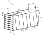
- FIG. 2 is a perspective view for explaining the insulating structure and the tape winding conductor according to the first embodiment.
- a plurality of stator winding conductors 24 constituting the stator winding 22 are laminated and arranged in two rows to form a laminated conductor 23 with 14 bodies.
- the number of stacked layers is 7 and the number of rows is 2 as an example, and the number of layers is not limited to these.
- Each of the stator winding conductors 24 is provided with a turn insulation 25 on the outside thereof and is covered with the turn insulation 25. Therefore, the outer surface of the laminated conductor 23 is also covered with the turn insulation 25.
- the main insulating tape 40 is wound as the main insulation on the outer side of the laminated conductor 23 to which the turn insulation 25 is applied, and the main insulating portion 49 is formed on the outer side of the laminated conductor 23 to form the tape wound conductor 50.
- the width of the main insulating tape 40 is W.
- the main insulating tape 40 is wound in a spiral shape when viewed in the longitudinal direction of the laminated conductor 23.
- the winding method at this time is a half wrap method. That is, the pitch of the helix is, for example, W / 2 that is half the width W of the main insulating tape 40. That is, it is wound so as to overlap with the main insulating tape 40 wound in the previous turn.
- the winding method is not limited to the half wrap method.
- the overlapping width may be changed.
- interval, without overlapping may be sufficient. In this case, the second winding is performed such that, for example, half the width of the main insulating tape 40 is shifted in the longitudinal direction.
- the second winding is further performed from above, and the main insulating tape 40 is layered.
- the winding of the main insulating tape 40 is not limited to twice. For example, it may be three times or more, and may be once, and is selected according to the required insulation performance.
- stator winding conductors 24 is subjected to individual insulation treatment, and mica insulation treatment may be performed from the outside thereof.
- FIG. 3 is a cross-sectional view schematically showing a configuration of a main insulating tape having an insulating structure according to the first embodiment.
- the main insulating tape 40 constituting the main insulating portion 49 penetrates into the main insulating layer 41, the fiber reinforced portion 42, and the fiber reinforced portion 42, and a nanoparticle-containing joint that joins the fiber reinforced portion 42 and the main insulating layer 41.
- the polymer polymer 43 for use is included.
- the main insulating layer 41 is a part that basically assumes an insulating function.
- the fiber reinforced portion 42 is a portion having a function of securing the strength as the main insulating tape 40 by supporting the main insulating layer 41 along the main insulating layer 41.
- the material of the main insulating layer 41 is, for example, mica, asbestos, or porcelain.
- the material of the fiber reinforcement part 42 is glass fiber etc., for example, and is normally knitted in mesh shape.
- the nanoparticle-containing bonding polymer 43 is, for example, an unsaturated polyester resin or an epoxy resin.
- the thickness of the main insulating layer 41 is, for example, about 100 ⁇ m. Moreover, the thickness of the fiber reinforced part 42 is thinner than this, for example, about 30 micrometers.
- the fiber reinforced portion 42, the nanoparticle-containing bonding polymer polymer 43 and the main insulating layer 41 are illustrated as the constituent parts of the main insulating tape 40. It has the role of joining the main insulating layer 41 and the fiber reinforced portion 42 while immersing in the fiber reinforced portion 42. For this reason, there is almost no thickness of the part only of the polymer polymer 43 for a joint containing a nanoparticle, and the main insulating layer 41 and the fiber reinforcement part 42 are the states which are almost substantially mutually contacting.
- Nanoparticles are kneaded in the polymer polymer 43 for bonding with nanoparticles.
- the nanoparticles for example, silicon dioxide (SiO 2 ), aluminum oxide (Al 2 O 3 ), magnesium oxide (MgO), boron nitride (BN), carbon nanotube (CNT), or the like can be used.
- Nanoparticles are generally said to include particles having a particle size of about several hundred nm.
- the nanoparticles used in the present embodiment are those having a particle size of 100 nm or less, that is, about several tens of nm. When a film having a thickness of about several hundreds of nanometers exceeding 100 nm is used, it is considered that the following effects cannot be expected.
- a manufacturing method of a particle having a particle size of 100 nm or less there is a method of manufacturing by growing from a finer one chemically. Or you may grind
- nanoparticles those having a size of 100 nm or less are referred to as nanoparticles.
- the main insulating tape 40 is wound with the main insulating layer 41 side on the insulating object side and the fiber reinforced portion 42 on the outside.
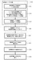
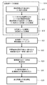
- FIG. 4 is a flowchart showing the procedure of the insulating structure manufacturing method according to the first embodiment.
- the main insulating tape 40 is manufactured (step S10). Specifically, first, nanoparticles are kneaded into the bonding polymer (step S11). That is, nanoparticles are kneaded with the bonding polymer to prepare the bonding polymer 43 with nanoparticles.
- step S12 the sheet-like main insulating layer 41 and the sheet-like fiber reinforced portion 42 are adhered by the polymer polymer 43 for bonding with nanoparticles to produce a main insulating sheet 40a with nanoparticles.
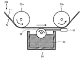
- FIG. 5 is an elevational sectional view showing the state of the main insulating sheet manufacturing step.
- the polymer polymer 43 for bonding with nanoparticles is applied to the sheet-like fiber reinforced portion 42 by using a coating method called a micro gravure method.
- a sheet-like main insulating layer 41 spreading in a plane and a sheet-like fiber reinforced portion 42 spreading along the same are prepared. These are available as raw materials for manufacturing the main insulating tape, that is, as materials for manufacturing the main insulating tape.
- the sheet-like main insulating layer 41 and the sheet-like fiber reinforced portion 42 are overlapped in advance.
- the stacked laminated sheets are continuously driven by a roller 55a and a roller 55b so that the fiber reinforced portion 42 is on the lower side and the main insulating layer 41 is on the upper side.
- the micro gravure roll 56 is in contact with the fiber reinforced portion 42 from below.
- the lower part of the micro gravure roll 56 is immersed in the bonding polymer polymer 43 containing liquid nanoparticles stored in the container 58.
- the micro gravure roll 56 rotates in a direction opposite to the moving direction of the laminated sheet.
- the polymer polymer 43 for bonding with nanoparticles in the container 58 is conveyed upward in a state of adhering to the surface of the microgravure roll 56.
- the excess polymer polymer 43 for bonding containing nanoparticles is removed.
- the polymer polymer 43 for bonding with nanoparticles that has not been removed by the doctor blade 57 contacts the laminated sheet and adheres to the fiber reinforced portion 42 of the laminated sheet.
- the nanoparticle-containing bonding polymer 43 attached to the fiber reinforced portion 42 penetrates into the fiber reinforced portion 42 and reaches the main insulating layer 41. In this way, the polymer polymer 43 for bonding with nanoparticles bonds the main insulating layer 41 and the fiber reinforced portion 42. In this way, the main insulating sheet 40a is manufactured.
- the main insulating sheet 40a is cut to manufacture the main insulating tape 40 (step S13).
- step S21 taping is performed around the laminated conductor 23 with the main insulating tape 40 (step S21). As a result, the tape winding conductor 50 is formed.
- FIG. 6 is a longitudinal sectional view showing the configuration of the integrated winding assembly.
- the integrated winding assembly 90 includes a stator core 21, a stator winding 22, and a frame 6 disposed on the outer side in the radial direction.
- the stator winding 22 is formed by connecting the tape winding conductor 50 (FIG. 2) after being accommodated in a plurality of slots (not shown).
- the slots are formed on the inner surface of the stator core 21 so as to extend to both ends in the axial direction of the stator core 21 at intervals in the circumferential direction.
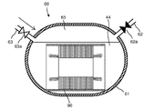
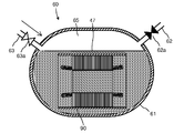
- FIG. 7 is an elevational sectional view showing a state of the vacuuming step.
- the integrated winding assembly 90 is housed in the impregnation container 61 of the impregnation apparatus 60.
- the impregnation container 61 can be divided into upper and lower parts, and the upper and lower parts can be joined with a flange (not shown).
- FIG. 8 is an elevational sectional view showing the state of the press-fitting step of the impregnating polymer. Specifically, after the impregnation vessel 61 is evacuated in step S23, the vacuum exhaust valve 62a on the vacuum exhaust pipe 62 is closed, and the polymer supply valve 63a on the polymer supply pipe 63 is closed. And the impregnating polymer 44 is supplied into the impregnation container. Supply of the polymer polymer for impregnation 44 is performed until the inside of the winding built-in unit 90 is sufficiently immersed in the polymer polymer for impregnation 44.
- the pressurized gas 65 is supplied into the impregnation container 61 from the polymer supply pipe 63, and the impregnation container 61 is supplied. Pressurize the inside.
- the pressurized gas 65 is, for example, an inert gas that is not reactive with the impregnating polymer 44.
- the impregnating polymer 44 penetrates into the main insulating tape 40 applied around the laminated conductor 23, and the main insulating tape 40 impregnates the impregnating polymer 44 into the main insulating tape 40.
- the polymer polymer 44 for use is impregnated to form a polymer polymer portion 45 (FIG. 9).
- the impregnating polymer 44 penetrates into the main insulating tape 40, the polymer polymer 43 for bonding with nanoparticles is reached, the polymer polymer 43 for bonding with nanoparticles is dissolved, and the dissolved nanoparticles are contained.
- the bonding polymer 43 and the impregnation polymer 44 are mixed.
- the nanoparticles in the polymer polymer 43 for bonding with nanoparticles are dispersed around the fiber reinforced portion 42 having the highest concentration, and are dispersed throughout the polymer polymer portion 45 of the main insulating tape 40. spread.
- the polymer polymer 44 for impregnation is solidified (step S25). Specifically, the integrated winding 90 is taken out from the impregnation container 61, and the polymer part 45 (FIG. 9) mainly containing the polymer polymer 42 for impregnation with nanoparticles is solidified.
- the polymer is a thermosetting resin such as an epoxy resin, it is cured by heating or the like.
- the high molecular polymer is a thermoplastic resin, it is cooled and solidified.
- FIG. 9 is a cross-sectional view schematically showing the configuration of the insulating structure according to the first embodiment. The cross section along the longitudinal direction of the laminated conductor 23 which is an insulation object is shown.
- FIG. 9 shows a case where the main insulating tape 40 is wound twice, and the taping layer A by the first winding and the taping layer B by the second winding are formed. Show.
- the insulating structure 30 includes a main insulating layer 41 that is a main insulating portion of the main insulating tape 40 (FIG. 3), a fiber reinforced portion 42 (FIG. 3), and a polymer portion 45.
- the polymer portion 45 is formed by impregnating the polymer polymer 43 for bonding with nanoparticles existing in the fiber reinforced portion 42 and between the fiber reinforced portion 42 and the main insulating layer 41.
- the united body 44 is formed by permeation.
- a polymer part 45 is formed on the outside of the main insulating layer 41 by the impregnating polymer 44 adhering during the impregnation treatment.
- a polymer portion 45 is formed as shown in FIG.
- the thickness of the main insulating layer 41 is displayed extremely thin in order to emphasize the polymer portion 45 formed by entering the fiber reinforced portion 42, and the fiber reinforced portion is also shown.
- the display of the unit 42 is omitted.
- the main insulating layers 41 adjacent to each other in the longitudinal direction of the laminated conductor 23 overlap each other by half of the width. This is a result of winding the main insulating tape 40 described above.
- the nanoparticles 48 contained in the polymer polymer 43 for bonding with nanoparticles are scattered.
- FIG. 10 is a cross-sectional view schematically showing the progress of the electric tree in the conventional insulating structure.
- a curve with a thick arrow schematically shows the path of progress of the electrical tree.
- the high polymer part 45a does not contain nanoparticles.
- the electrical tree emanating from the laminated conductor 23 reaches the surface while passing through the polymer portion 45a between the main insulating layers 41 through a substantially shortest route.
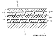
- FIG. 11 is a cross-sectional view schematically showing the effect of the insulating structure according to the first embodiment.
- the insulating structure 30 according to the present embodiment nanoparticles 48 are scattered in the polymer portion 45 between the main insulating layers 41. For this reason, when the nanoparticles 48 are not present, the electric tree advances in the shortest route, and the appearance is changed while changing the direction due to the presence of the nanoparticles 48. As a result, the progress rate is significantly reduced as compared with the case where the nanoparticles 48 are not present. Or the progress stops on the way.
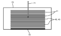
- FIG. 12 is a longitudinal sectional view schematically showing a first test system for an insulating structure according to the first embodiment.
- the first test body 70 simulates a state in which a plurality of mica tapes are stacked. Therefore, the material of the main insulating layer 41 is mica, the fiber reinforced portion 42 is glass fiber, and the material of the high polymer portion 45 is epoxy resin. Epoxy resins do not contain nanoparticles.
- a plurality of main insulating layers 41 are stacked substantially in parallel with each other. Between the main insulating layers 41 adjacent to each other, a fiber reinforced portion 42 and a high polymer portion 45 are disposed.
- the thickness of the main insulating layer 41 was 100 to 140 ⁇ m per layer, and the thickness of the fiber reinforced portion 42 and the polymer portion 45 was 10 to 40 ⁇ m per layer.
- the thickness of the main insulating layer 41 is displayed extremely thin in order to emphasize the polymer portion 45 formed by entering the fiber reinforced portion 42, Moreover, the display of the fiber reinforcement part 42 is abbreviate
- a first test system was set in which the needle electrode 71 was inserted at a substantially central position in the plane of the first test body 70.
- an AC voltage of 50 Hz was applied between the needle electrode 71 and the ground plate 72, and the partial discharge start voltage was measured. After detecting the partial discharge start voltage, the applied voltage was increased at a boosting rate of 600 V / sec until the sample breakdown.
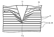
- FIG. 13 is a detailed longitudinal sectional view of a portion around the needle electrode schematically showing a test result of the insulating structure according to the first embodiment.
- the electric tree 75 has advanced in the direction in which the main insulating layer 41 spreads by sewing between the main insulating layers 41 adjacent to each other in the vertical direction, as indicated by broken line arrows in FIG. Further, the electric tree 75 does not originate from the tip portion 71a of the needle electrode 71 having the highest electric field intensity, but from a position slightly off the tip portion 71a (a portion slightly on the side of the tip portion 71a in FIG. 13). The electric tree 75 progresses with a spread in the direction in which the main insulating layer 41 spreads.
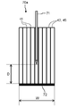
- FIG. 14 is a longitudinal sectional view schematically showing a second test system of the insulating structure according to the first embodiment.
- a needle electrode is inserted into the glass cloth portion between the adjacent mica layers, and the polymer polymer portion 45 has no nanoparticles, Each test was performed for the case where it existed.
- the second test body 70 a simulates a state in which a plurality of mica tapes are stacked in the same manner as the first test body 70. Therefore, the material of the main insulating layer 41 is mica, the fiber reinforced portion 42 is glass fiber, and the material of the high polymer portion 45 is epoxy resin.
- the epoxy resin may or may not contain nanoparticles.
- a plurality of main insulating layers 41 are stacked substantially in parallel with each other. Between the main insulating layers 41 adjacent to each other, a fiber reinforced portion 42 and a high polymer portion 45 are disposed.
- a ground plate 72 is provided at an end portion where the main insulating layer 41 and the fiber reinforced portion 42 extend.
- the needle electrode 71 is inserted in the region of the fiber reinforced portion 42 and the polymer portion 45 sandwiched between the main insulating layers 41 adjacent to each other.
- the test was conducted using a system in which the width W of the ground plate was about 4 mm, the depth was about 25 mm, and the distance D between the needle electrode 71 and the ground plate 72 was about 3 mm.
- the time until the dielectric breakdown occurs when the state of 15 kV is maintained was maintained. And compared. In the test results, for example, it was about 1.9 hours when the nanoparticles were not present, whereas it was 3 weeks or more when the nanoparticles were present. In this case, the average particle diameter of the nanoparticles was 10 to 20 nm, and the mixing ratio of the nanoparticles was 10 wt%.
- the thermal conductivity is about 0.25 W / m ⁇ K, for example, 0.40 W / m ⁇ K.
- the thermal conductivity is about 0.25 W / m ⁇ K, for example, 0.40 W / m ⁇ K.
- the heat dissipation effect can be further increased, a current can be further flowed, so that the storage output, that is, the output per unit volume can be increased.
- nanoparticles are mixed in a polymer, depending on the combination, the viscosity of the polymer may increase or the usable life of the polymer may be shortened. In addition, the effect of nanoparticles can be exhibited.
- the progress of the electric tree in the insulating structure can be suppressed, and the storage output can be improved and the efficiency of the assembly work can be improved.
- the polymer polymer with nanoparticles is directly attached, including the case of high concentration where it is difficult to penetrate the nanoparticles, so that nanoparticles of any concentration are applied. It is possible.
- FIG. 15 is a flowchart showing the procedure of the insulating structure manufacturing method according to the second embodiment.
- This embodiment is a modification of the first embodiment.
- the polymer for impregnation kneaded with nanoparticles is press-fitted (step S31).
- step S31 the polymer for impregnation kneaded with nanoparticles
- FIG. 16 is an elevational sectional view showing the state of the press-fitting step of the polymer polymer for impregnation with nanoparticles in the insulating structure manufacturing method according to the second embodiment.
- step S23 in which the inside of the impregnation container 61 of the impregnation apparatus 60 is evacuated, the winding-incorporated integrated article 90 is immersed in the polymer polymer 47 for impregnation with nanoparticles.
- the concentration of the nanoparticles in the polymer polymer 47 for impregnation with nanoparticles may be different from the concentration of the nanoparticles in the polymer polymer 43 for bonding with nanoparticles, depending on the combination of the two concentrations. The optimal nanoparticle concentration distribution can be obtained.
- the inside of the impregnation container 61 is pressurized, and the polymer polymer 47 for impregnation with nanoparticles is press-fitted into the tape winding conductor 50 in the winding built-in integral 90.
- the nanoparticles are included not only in the bonding polymer 43 but also in the impregnation polymer 44, the dispersed state of the nanoparticles can be secured in a wide range. . As a result, the effect of the first embodiment can be further ensured.
Landscapes
- Engineering & Computer Science (AREA)
- Power Engineering (AREA)
- Manufacturing & Machinery (AREA)
- Insulation, Fastening Of Motor, Generator Windings (AREA)
- Manufacture Of Motors, Generators (AREA)
- Inorganic Insulating Materials (AREA)
- Manufacturing Of Electric Cables (AREA)
- Insulating Bodies (AREA)
Priority Applications (5)
| Application Number | Priority Date | Filing Date | Title |
|---|---|---|---|
| JP2018524585A JP6816141B2 (ja) | 2016-07-01 | 2016-07-01 | 絶縁構造製造方法 |
| PCT/JP2016/003164 WO2018002972A1 (ja) | 2016-07-01 | 2016-07-01 | 絶縁構造製造方法、絶縁構造および回転電機 |
| EP16907207.1A EP3480921B1 (en) | 2016-07-01 | 2016-07-01 | Method for producing insulating structure |
| CN201680084475.0A CN109075643A (zh) | 2016-07-01 | 2016-07-01 | 绝缘结构制造方法、绝缘结构及旋转电机 |
| US16/227,933 US10931159B2 (en) | 2016-07-01 | 2018-12-20 | Electrical insulating structure producing method, electrical insulating structure and rotating electrical machine |
Applications Claiming Priority (1)
| Application Number | Priority Date | Filing Date | Title |
|---|---|---|---|
| PCT/JP2016/003164 WO2018002972A1 (ja) | 2016-07-01 | 2016-07-01 | 絶縁構造製造方法、絶縁構造および回転電機 |
Related Child Applications (1)
| Application Number | Title | Priority Date | Filing Date |
|---|---|---|---|
| US16/227,933 Continuation US10931159B2 (en) | 2016-07-01 | 2018-12-20 | Electrical insulating structure producing method, electrical insulating structure and rotating electrical machine |
Publications (1)
| Publication Number | Publication Date |
|---|---|
| WO2018002972A1 true WO2018002972A1 (ja) | 2018-01-04 |
Family
ID=60785373
Family Applications (1)
| Application Number | Title | Priority Date | Filing Date |
|---|---|---|---|
| PCT/JP2016/003164 WO2018002972A1 (ja) | 2016-07-01 | 2016-07-01 | 絶縁構造製造方法、絶縁構造および回転電機 |
Country Status (5)
| Country | Link |
|---|---|
| US (1) | US10931159B2 (zh) |
| EP (1) | EP3480921B1 (zh) |
| JP (1) | JP6816141B2 (zh) |
| CN (1) | CN109075643A (zh) |
| WO (1) | WO2018002972A1 (zh) |
Cited By (2)
| Publication number | Priority date | Publication date | Assignee | Title |
|---|---|---|---|---|
| WO2020144859A1 (ja) * | 2019-01-11 | 2020-07-16 | 東芝三菱電機産業システム株式会社 | 絶縁構造製造方法、絶縁構造製造装置、および回転電機 |
| WO2023132102A1 (ja) * | 2022-01-07 | 2023-07-13 | 日立Astemo株式会社 | 回転電機の固定子 |
Families Citing this family (2)
| Publication number | Priority date | Publication date | Assignee | Title |
|---|---|---|---|---|
| CN110707886B (zh) * | 2019-12-03 | 2021-04-20 | 哈尔滨电机厂有限责任公司 | 一种大型电机转子磁极极身绝缘贴附式粘接的工艺方法 |
| CN113506662B (zh) * | 2021-07-08 | 2022-07-12 | 萍乡强盛电瓷制造有限公司 | 一种盘形悬式瓷绝缘子加工用设备 |
Citations (4)
| Publication number | Priority date | Publication date | Assignee | Title |
|---|---|---|---|---|
| JPS63110929A (ja) * | 1986-10-22 | 1988-05-16 | アセア アクチーボラグ | 電気機器の固定子又は回転子におけるスロツト内に配置するためのコイル |
| JPH10174333A (ja) * | 1996-12-10 | 1998-06-26 | Fuji Electric Co Ltd | 回転機固定子コイル |
| WO2015053374A1 (ja) * | 2013-10-09 | 2015-04-16 | 日立化成株式会社 | プリプレグマイカテープ及びそれを用いたコイル |
| WO2016104141A1 (ja) * | 2014-12-22 | 2016-06-30 | 三菱電機株式会社 | 絶縁テープ及びその製造方法、並びに固定子コイル及びその製造方法、並びに発電機 |
Family Cites Families (15)
| Publication number | Priority date | Publication date | Assignee | Title |
|---|---|---|---|---|
| US2808981A (en) * | 1954-06-09 | 1957-10-08 | Nat Radiator Company | Universal foot for blower assembly |
| GB1352733A (en) * | 1971-07-08 | 1974-05-08 | Mullard Ltd | Electron multipliers |
| JPS5060705A (zh) * | 1973-10-01 | 1975-05-24 | ||
| KR960007166A (ko) * | 1994-08-10 | 1996-03-22 | 김은영 | 골판지 포장 충전재 제조방법과, 이를 수행하기 위한 골판지 권취 및 접착장치, 및 골판지 충전재 성형장치 |
| KR100359109B1 (ko) * | 2000-02-25 | 2002-11-04 | 삼성전자 주식회사 | 시트 코팅 장치 |
| CN1324615C (zh) * | 2002-07-04 | 2007-07-04 | 株式会社东芝 | 高导热性绝缘部件及其制造方法、电磁线圈 |
| US7524557B2 (en) * | 2002-07-04 | 2009-04-28 | Kabushiki Kaisha Toshiba | Highly heat conductive insulating member, method of manufacturing the same and electromagnetic device |
| JP4313141B2 (ja) * | 2003-09-30 | 2009-08-12 | 中川特殊鋼株式会社 | 磁性基材の積層体の製造方法、およびこれにより得られる磁性基材の積層体 |
| JP2006246599A (ja) * | 2005-03-02 | 2006-09-14 | Toshiba Corp | 半導電性テープ、半導電性テープの製造方法、絶縁コイル及び回転電機 |
| CN100506530C (zh) * | 2006-06-12 | 2009-07-01 | 苏州市好护理医疗用品有限公司 | 一种粘性弹性绷带的制作方法 |
| DE102011083409A1 (de) | 2011-09-26 | 2013-03-28 | Siemens Aktiengesellschaft | Isoliersysteme mit verbesserter Teilentladungsbeständigkeit, Verfahren zur Herstellung dazu |
| CN102510141B (zh) * | 2011-10-31 | 2014-01-29 | 安泰科技股份有限公司 | 轴向磁通电机用非晶、微晶或纳米晶合金定子铁心及其制造方法 |
| US9928935B2 (en) * | 2013-05-31 | 2018-03-27 | General Electric Company | Electrical insulation system |
| CN103400638B (zh) * | 2013-07-30 | 2016-01-20 | 苏州巨峰电气绝缘系统股份有限公司 | 一种耐电晕槽绝缘材料及其制备方法 |
| CN204746771U (zh) * | 2015-06-30 | 2015-11-11 | 浙江索凡胶粘制品有限公司 | 一种能够自动上胶自动调节压辊高度的涂布机上胶装置 |
-
2016
- 2016-07-01 EP EP16907207.1A patent/EP3480921B1/en active Active
- 2016-07-01 CN CN201680084475.0A patent/CN109075643A/zh active Pending
- 2016-07-01 JP JP2018524585A patent/JP6816141B2/ja active Active
- 2016-07-01 WO PCT/JP2016/003164 patent/WO2018002972A1/ja unknown
-
2018
- 2018-12-20 US US16/227,933 patent/US10931159B2/en active Active
Patent Citations (4)
| Publication number | Priority date | Publication date | Assignee | Title |
|---|---|---|---|---|
| JPS63110929A (ja) * | 1986-10-22 | 1988-05-16 | アセア アクチーボラグ | 電気機器の固定子又は回転子におけるスロツト内に配置するためのコイル |
| JPH10174333A (ja) * | 1996-12-10 | 1998-06-26 | Fuji Electric Co Ltd | 回転機固定子コイル |
| WO2015053374A1 (ja) * | 2013-10-09 | 2015-04-16 | 日立化成株式会社 | プリプレグマイカテープ及びそれを用いたコイル |
| WO2016104141A1 (ja) * | 2014-12-22 | 2016-06-30 | 三菱電機株式会社 | 絶縁テープ及びその製造方法、並びに固定子コイル及びその製造方法、並びに発電機 |
Cited By (2)
| Publication number | Priority date | Publication date | Assignee | Title |
|---|---|---|---|---|
| WO2020144859A1 (ja) * | 2019-01-11 | 2020-07-16 | 東芝三菱電機産業システム株式会社 | 絶縁構造製造方法、絶縁構造製造装置、および回転電機 |
| WO2023132102A1 (ja) * | 2022-01-07 | 2023-07-13 | 日立Astemo株式会社 | 回転電機の固定子 |
Also Published As
| Publication number | Publication date |
|---|---|
| US20190149009A1 (en) | 2019-05-16 |
| CN109075643A (zh) | 2018-12-21 |
| EP3480921A1 (en) | 2019-05-08 |
| US10931159B2 (en) | 2021-02-23 |
| EP3480921B1 (en) | 2022-06-22 |
| JP6816141B2 (ja) | 2021-01-20 |
| EP3480921A4 (en) | 2020-03-04 |
| JPWO2018002972A1 (ja) | 2019-06-13 |
Similar Documents
| Publication | Publication Date | Title |
|---|---|---|
| WO2018002970A1 (ja) | 絶縁構造製造方法、絶縁構造および回転電機 | |
| WO2018002972A1 (ja) | 絶縁構造製造方法、絶縁構造および回転電機 | |
| JP4913551B2 (ja) | 回転電機巻線及び回転電機並びにそれに用いる半導電性絶縁基材 | |
| JP4103390B2 (ja) | 絶縁材及び電機巻線とその製造法 | |
| WO2018002971A1 (ja) | 絶縁構造製造方法、絶縁構造および回転電機 | |
| US10903710B2 (en) | Producing method for electrical insulating structure, electrical insulating structure and rotating electrical machine | |
| JP2016072301A (ja) | 絶縁材、この絶縁材を用いた絶縁コイル、これらの製造方法、ならびにこの絶縁コイルを具備する装置 | |
| WO2018002974A1 (ja) | コロナ放電防止構造製造方法、コロナ放電防止構造および回転電機 | |
| WO2020144859A1 (ja) | 絶縁構造製造方法、絶縁構造製造装置、および回転電機 | |
| US20220356311A1 (en) | Method of producing resin and method of producing insulating structure | |
| WO2023170794A1 (ja) | 回転電機及び絶縁テープ |
Legal Events
| Date | Code | Title | Description |
|---|---|---|---|
| 121 | Ep: the epo has been informed by wipo that ep was designated in this application |
Ref document number: 16907207 Country of ref document: EP Kind code of ref document: A1 |
|
| ENP | Entry into the national phase |
Ref document number: 2018524585 Country of ref document: JP Kind code of ref document: A |
|
| NENP | Non-entry into the national phase |
Ref country code: DE |
|
| ENP | Entry into the national phase |
Ref document number: 2016907207 Country of ref document: EP Effective date: 20190201 |