WO2017222026A1 - Appareil d'héliostat et procédé de génération d'énergie solaire - Google Patents
Appareil d'héliostat et procédé de génération d'énergie solaire Download PDFInfo
- Publication number
- WO2017222026A1 WO2017222026A1 PCT/JP2017/023091 JP2017023091W WO2017222026A1 WO 2017222026 A1 WO2017222026 A1 WO 2017222026A1 JP 2017023091 W JP2017023091 W JP 2017023091W WO 2017222026 A1 WO2017222026 A1 WO 2017222026A1
- Authority
- WO
- WIPO (PCT)
- Prior art keywords
- solar cell
- panel
- frame
- angle
- power generation
- Prior art date
Links
- 238000010248 power generation Methods 0.000 title claims abstract description 139
- 238000000034 method Methods 0.000 title claims description 28
- 230000005484 gravity Effects 0.000 claims abstract description 11
- 230000000149 penetrating effect Effects 0.000 claims description 6
- 239000013598 vector Substances 0.000 description 8
- 230000007423 decrease Effects 0.000 description 6
- 238000009434 installation Methods 0.000 description 6
- 238000007664 blowing Methods 0.000 description 4
- 239000002803 fossil fuel Substances 0.000 description 4
- 238000012423 maintenance Methods 0.000 description 4
- 230000000694 effects Effects 0.000 description 3
- NJPPVKZQTLUDBO-UHFFFAOYSA-N novaluron Chemical compound C1=C(Cl)C(OC(F)(F)C(OC(F)(F)F)F)=CC=C1NC(=O)NC(=O)C1=C(F)C=CC=C1F NJPPVKZQTLUDBO-UHFFFAOYSA-N 0.000 description 3
- CURLTUGMZLYLDI-UHFFFAOYSA-N Carbon dioxide Chemical compound O=C=O CURLTUGMZLYLDI-UHFFFAOYSA-N 0.000 description 2
- 238000004364 calculation method Methods 0.000 description 2
- 239000000446 fuel Substances 0.000 description 2
- 239000000463 material Substances 0.000 description 2
- 238000011084 recovery Methods 0.000 description 2
- 229910002092 carbon dioxide Inorganic materials 0.000 description 1
- 239000001569 carbon dioxide Substances 0.000 description 1
- 238000010586 diagram Methods 0.000 description 1
- 230000005611 electricity Effects 0.000 description 1
- 239000005431 greenhouse gas Substances 0.000 description 1
- 239000003208 petroleum Substances 0.000 description 1
- 238000004088 simulation Methods 0.000 description 1
Images


Classifications
-
- H—ELECTRICITY
- H02—GENERATION; CONVERSION OR DISTRIBUTION OF ELECTRIC POWER
- H02S—GENERATION OF ELECTRIC POWER BY CONVERSION OF INFRARED RADIATION, VISIBLE LIGHT OR ULTRAVIOLET LIGHT, e.g. USING PHOTOVOLTAIC [PV] MODULES
- H02S20/00—Supporting structures for PV modules
- H02S20/30—Supporting structures being movable or adjustable, e.g. for angle adjustment
- H02S20/32—Supporting structures being movable or adjustable, e.g. for angle adjustment specially adapted for solar tracking
-
- F—MECHANICAL ENGINEERING; LIGHTING; HEATING; WEAPONS; BLASTING
- F24—HEATING; RANGES; VENTILATING
- F24S—SOLAR HEAT COLLECTORS; SOLAR HEAT SYSTEMS
- F24S23/00—Arrangements for concentrating solar-rays for solar heat collectors
- F24S23/70—Arrangements for concentrating solar-rays for solar heat collectors with reflectors
- F24S23/77—Arrangements for concentrating solar-rays for solar heat collectors with reflectors with flat reflective plates
-
- F—MECHANICAL ENGINEERING; LIGHTING; HEATING; WEAPONS; BLASTING
- F24—HEATING; RANGES; VENTILATING
- F24S—SOLAR HEAT COLLECTORS; SOLAR HEAT SYSTEMS
- F24S30/00—Arrangements for moving or orienting solar heat collector modules
- F24S30/40—Arrangements for moving or orienting solar heat collector modules for rotary movement
- F24S30/45—Arrangements for moving or orienting solar heat collector modules for rotary movement with two rotation axes
-
- F—MECHANICAL ENGINEERING; LIGHTING; HEATING; WEAPONS; BLASTING
- F24—HEATING; RANGES; VENTILATING
- F24S—SOLAR HEAT COLLECTORS; SOLAR HEAT SYSTEMS
- F24S50/00—Arrangements for controlling solar heat collectors
- F24S50/20—Arrangements for controlling solar heat collectors for tracking
-
- H—ELECTRICITY
- H02—GENERATION; CONVERSION OR DISTRIBUTION OF ELECTRIC POWER
- H02S—GENERATION OF ELECTRIC POWER BY CONVERSION OF INFRARED RADIATION, VISIBLE LIGHT OR ULTRAVIOLET LIGHT, e.g. USING PHOTOVOLTAIC [PV] MODULES
- H02S40/00—Components or accessories in combination with PV modules, not provided for in groups H02S10/00 - H02S30/00
- H02S40/20—Optical components
- H02S40/22—Light-reflecting or light-concentrating means
-
- Y—GENERAL TAGGING OF NEW TECHNOLOGICAL DEVELOPMENTS; GENERAL TAGGING OF CROSS-SECTIONAL TECHNOLOGIES SPANNING OVER SEVERAL SECTIONS OF THE IPC; TECHNICAL SUBJECTS COVERED BY FORMER USPC CROSS-REFERENCE ART COLLECTIONS [XRACs] AND DIGESTS
- Y02—TECHNOLOGIES OR APPLICATIONS FOR MITIGATION OR ADAPTATION AGAINST CLIMATE CHANGE
- Y02E—REDUCTION OF GREENHOUSE GAS [GHG] EMISSIONS, RELATED TO ENERGY GENERATION, TRANSMISSION OR DISTRIBUTION
- Y02E10/00—Energy generation through renewable energy sources
- Y02E10/40—Solar thermal energy, e.g. solar towers
- Y02E10/47—Mountings or tracking
-
- Y—GENERAL TAGGING OF NEW TECHNOLOGICAL DEVELOPMENTS; GENERAL TAGGING OF CROSS-SECTIONAL TECHNOLOGIES SPANNING OVER SEVERAL SECTIONS OF THE IPC; TECHNICAL SUBJECTS COVERED BY FORMER USPC CROSS-REFERENCE ART COLLECTIONS [XRACs] AND DIGESTS
- Y02—TECHNOLOGIES OR APPLICATIONS FOR MITIGATION OR ADAPTATION AGAINST CLIMATE CHANGE
- Y02E—REDUCTION OF GREENHOUSE GAS [GHG] EMISSIONS, RELATED TO ENERGY GENERATION, TRANSMISSION OR DISTRIBUTION
- Y02E10/00—Energy generation through renewable energy sources
- Y02E10/50—Photovoltaic [PV] energy
- Y02E10/52—PV systems with concentrators
Definitions
- the present invention relates to a heliostat device provided with a reflector or a solar cell panel, and also relates to a solar power generation method using the heliostat device provided with a solar cell panel.
- a solar power generation apparatus including a solar cell module (solar cell panel) can be cited.
- solar cell panel There are two types of solar cell panels in which the installation angle is fixed (fixed type) and those that can be adjusted in accordance with the movement of the sun (solar tracking type) (Patent Document 1).
- solar tracking type solar tracking type
- Patent Document 1 a solar thermal collector is mentioned, for example, there exists a tower type thing.
- a heliostat device adjusts the angles of the reflecting surfaces of a plurality of reflecting mirrors arranged around the tower, condenses sunlight on a receiver provided on the tower, and collects solar heat.
- the fixed panel of the solar power generation device has the maximum power generation amount when the sun goes south, and is almost zero immediately after sunrise and just before sunset.
- the amount of power generation gradually increases after sunrise, reaches a maximum in the middle of the south, gradually attenuates as the sun tilts west, and becomes almost zero just before sunset.
- the power generation amount of the fixed type changes like a bell during a day.
- the amount of power generation can be slightly increased by installing the fixed panel in the south at an inclination angle of 20-30 °. This is due to the fact that the solar altitude fluctuates approximately 50 ° in summer and winter in the middle and south, and in Japan it decreases to nearly 10 ° in winter, so a 35 ° tilt is optimal.
- the optimum angle and gap are selected based on the balance between the loss due to the shadow and the increase due to the inclination angle. Actually, the size of the gap is determined so that shadows cannot be made after 9 am.
- the inclination angle of 10-30 At present, it is installed with a gap between the front row and the rear row at an angle of 0.3 to 0.4 as the access road with respect to the site area.
- the shadows that can appear in the back row in the morning and evening it is necessary to increase the gap or set the tilt angle lower.
- the gap is made too large, the area of the gap will exceed the minimum required area for the access road, and the excess will be a wasteful ground that does not generate electricity at all, so measures to increase the gap are taken. Absent.
- the inclination angle should be zero, but the access road cannot be taken. As a result of these, an inclination angle of 10 to 30 ° is selected. The gap between the front row and the rear row is taken so that the shadow of the front row does not hit the back row during winter solstice, and it is used as an access road.
- access roads are indispensable for the method of installing solar panels fixed on a large scale with mega solar, which makes it impossible to avoid a decrease in power generation efficiency per land area. ing.
- the amount of power generated by a fixed solar panel changes like a bell during the day, so instead of this, the fixed type that the amount of power generated is constant from 9:00 am to the evening.
- a solar cell panel installation method different from the above is desired.
- the solar panel can be operated so that the influence of shadows can be suppressed in response to the ever-changing sun and at the same time, the place where the sun hits the ground, the amount of power generation per land is increased. It is possible to do this, and it has great significance in the development of renewable energy at high land costs like Japan.
- the solar tracking type solar cell panel can face the sun, when it is oriented so as to be perpendicular to the sun, it is possible to obtain a power generation amount equivalent to that in the south-central time.
- the conventional solar tracking type is called a graticule type, and as shown in FIG. 12, a power generation panel comprising a solar cell panel and a frame that supports the solar cell panel is supported by a support column.
- the power generation panel can be moved up and down and left and right with the vertical rotation means and the left and right rotation means always facing the sun.
- each solar cell panel in the front row casts shadows on the solar cell panel in the back row from the sunrise when the solar altitude is low until around 9 o'clock and after about 4 o'clock before sunset.
- the amount will decrease. Therefore, for example, each solar cell panel is arranged separately, but this needs to be arranged apart from the case of the fixed type panel, and land use efficiency becomes low, and power generation efficiency decreases. Will lead to.
- a plurality of heliostat devices that track the sun are arranged around the tower. Similarly, in order to prevent shadow interference, each of these heliostat devices A certain amount of space is also required between them.
- the present invention has been made in view of the above problems, and is a type that follows the movement of the sun. Even if the arrangement interval is narrowed, shadow interference is less likely to occur than conventional products, and more efficiently.
- An object of the present invention is to provide a heliostat device capable of obtaining solar energy. It is another object of the present invention to provide a solar power generation method that uses a heliostat device that follows the movement of the sun, suppresses the occurrence of shadow interference than before, and can obtain solar energy more efficiently. .
- the present invention comprises at least one reflecting mirror or solar cell panel that reflects sunlight, and the angle of the reflecting surface of the reflecting mirror or the panel surface of the solar cell panel depends on the movement of the sun.
- a heliostat device that adjusts following, A frame that supports the reflecting mirror or the solar cell panel; An elevation angle rotation axis having the east-west direction as an axial direction for rotating the frame in the north-south direction, and an azimuth rotation axis having the north-south direction as an axial direction for rotating the frame in the east-west direction, the elevation rotation A gyro mechanism in which an axis and the azimuth rotation axis are orthogonal to each other; A support for supporting the frame via the gyro mechanism, The frame and the reflecting mirror or the solar cell panel are integrally rotated in the north-south direction around the elevation angle rotation axis as a rotation axis, so that the reflecting surface of the reflecting mirror supported by the frame or the solar cell panel The angle of the north-s
- the angle of the reflecting surface of the reflector and the panel surface of the solar panel (power generation) as well as the fixed type and the solar tracking type heliostat device can be adjusted with a higher degree of freedom. For this reason, it can be directed to the sun even in a time zone where the solar altitude is low, and more solar energy can be obtained than the fixed type, thereby improving the power generation efficiency. Further, even if a plurality of heliostat devices are arranged side by side, shadow interference with other heliostat devices is less likely to occur than with the graduation table type. Therefore, it can be arranged with a narrower gap than that of the theodolite type, and land use efficiency can be improved and power generation efficiency can also be improved.
- the power generation panel is smaller than the conventional graduation table type It can be easily rotated with force, and the angle of the solar cell panel can be adjusted with less power. Therefore, it is possible to operate the power generation panel by supplying power to the storage batteries etc. provided for each rather than drawing the wiring to the heliostat device and supplying power to each storage battery etc. Become.
- the gyro mechanism is A cylindrical body arranged such that the longitudinal direction is along the azimuth rotation axis; An azimuth rotary shaft that passes through the cylinder in the longitudinal direction and is located on the azimuth rotary axis; A connecting cover that connects both ends of the penetrating azimuth rotating shaft; A connecting arm that connects the connecting cover and the frame; Projecting from the cylindrical body in the short direction, and comprising a pair of elevation rotation shafts positioned on the elevation rotation shaft,
- the support column includes a bearing that supports the pair of elevation rotation shafts so as to be axially rotatable.
- connection cover, the connection arm, and the frame can be integrally rotated in the east-west direction
- the cylindrical body, the azimuth rotation shaft, the connection cover, the connection arm, and the frame are integrally north and south with the pair of elevation rotation shafts on the elevation rotation shaft as a rotation axis on the bearing of the support column. It can be rotatable in the direction.
- the gyro mechanism may include an elevation angle adjustment actuator for rotating the frame in the north-south direction and an azimuth angle adjustment actuator for rotating the frame in the east-west direction.
- a storage battery that supplies electric power for operating the gyro mechanism can be further provided.
- the angle of the power generation panel can be adjusted by operating the gyro mechanism even if no wiring is drawn on the heliostat device. Costs required for wiring installation and maintenance can be reduced.
- an auxiliary solar cell panel for charging the storage battery can be further provided.
- a plurality of the reflecting mirrors or solar cell panels may be provided, and the plurality of reflecting mirrors or solar cell panels may be arranged in a square shape on one frame.
- this invention arrange
- a solar power generation method for performing solar power generation When the plurality of heliostat devices are of a gyro type, and the panel surface of the solar cell panel is oriented perpendicular to sunlight, the panel surface, In the time zone when shadow does not occur on the panel surface of the solar panel of other heliostat devices, Adjusting the angle of the panel surface of the solar cell panel of each heliostat device perpendicular to sunlight, In the time zone when shadows appear on the panel surface of the solar panel of other heliostat devices, The shadow of the panel surface of the solar cell panel of each heliostat device is generated on the ground outside the panel surface of the solar cell panel of the other heliostat device, and the size of the shadow area generated on the ground surface On the basis of the angle of the panel surface of the solar cell panel
- the angle of the panel surface of the solar cell panel (the angle of the power generation panel) is more than that of the fixed type and the solar tracking type graduation heliostat device. It can be adjusted with a high degree of freedom. For this reason, it can be directed to the sun even in a time zone where the solar altitude is low, and more solar energy can be obtained than the fixed type, thereby improving the power generation efficiency. Further, even if a plurality of gyro-type heliostat devices are arranged side by side, shadow interference with other heliostat devices is less likely to occur than with a graduation type. Therefore, it can be arranged with a narrower gap than that of the theodolite type, and land use efficiency can be improved and power generation efficiency can also be improved.
- the solar cell panel is supported by a frame, An elevation angle rotation axis having the east-west direction as an axial direction for rotating the frame in the north-south direction, and an azimuth rotation axis having the north-south direction as an axial direction for rotating the frame in the east-west direction, the elevation rotation A gyro mechanism in which an axis and the azimuth rotation axis are orthogonal to each other;
- the frame is supported by a support through the gyro mechanism,
- the center of gravity of the power generation panel comprising the frame and the solar cell panel supported by the frame is made to coincide with the intersection where the elevation rotation axis and the azimuth rotation axis of the gyro mechanism are orthogonal to each other,
- the angle of the panel surface of the solar cell panel supported by the frame is adjusted by rotating the frame and the solar cell panel integrally in the north-south direction with the elevation angle rotation
- the center of gravity of the power generation panel coincides with the intersection (the center of the gyroscope) where the elevation angle rotation axis and the azimuth angle rotation axis of the gyro mechanism are orthogonal to each other. It can be easily rotated with a smaller force, and the angle of the solar cell panel can be adjusted with less power. Therefore, it is possible to operate the power generation panel by supplying power to the storage batteries etc. provided for each rather than drawing the wiring to the heliostat device and supplying power to each storage battery etc. Become.
- a cylindrical body arranged such that the longitudinal direction is along the azimuth rotation axis;
- An azimuth rotary shaft that passes through the cylinder in the longitudinal direction and is located on the azimuth rotary axis;
- a connecting cover that connects both ends of the penetrating azimuth rotating shaft;
- a connecting arm that connects the connecting cover and the frame; Protruding in a short direction from the cylindrical body, provided with a pair of elevation rotation shafts located on the elevation rotation shaft, As the support columns, those provided with bearings that support the pair of elevation rotation shafts so as to be axially rotatable are disposed.
- connection cover, the connection arm, and the frame are integrally rotated in the east-west direction
- the cylindrical body, the azimuth rotation shaft, the connection cover, the connection arm, and the frame are integrally north-south with the pair of elevation rotation shafts on the elevation rotation shaft as the rotation shaft on the bearing of the support column. Can rotate in the direction.
- An elevation angle adjusting actuator for rotating the frame in the north-south direction and an azimuth angle adjusting actuator for rotating the frame in the east-west direction can be used.
- a storage battery can be further arranged in the heliostat device, and power can be supplied from the storage battery to operate the gyro mechanism.
- an auxiliary solar cell panel can be further provided in the heliostat device, and the storage battery can be charged by the auxiliary solar cell panel.
- the heliostat device can be made more surely self-supporting.
- a plurality of the solar cell panels can be prepared, and the plurality of solar cell panels can be arranged in a square shape on one frame.
- the central part of the square shape is vacant, even if the wind is blowing, the wind can escape from the central part, and even if the power generation panel receives the wind, the heliostat device does not fall easily And it can control that a power generation panel shakes.
- the angle of the power generation panel can be adjusted more easily and with a higher degree of freedom, the sun can be tracked, and the arrangement distance between the heliostat devices is narrow. Shadow interference is less likely to occur. As a result, solar energy can be obtained efficiently, and power generation efficiency and the like can be improved.
- the angle of the power generation panel is adjusted according to whether or not shadow interference has occurred, it is possible to reliably prevent the occurrence of shadow interference and to consider the size of the shadow area on the ground. Energy recovery efficiency can be improved.
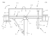
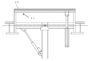
- FIG. 1 shows an example of a gyro-type heliostat device of the present invention that can be used in the photovoltaic power generation method of the present invention.
- the direction from the front to the back is the east-west direction
- the left-right direction is the north-south direction.
- the heliostat device 1 includes a power generation panel 2, a gyro mechanism 3, and a support column 4 as a whole.
- the power generation panel 2 is inclined to the west.
- the power generation panel 2 includes a solar cell panel 5 and a frame 6.
- a solar cell panel 5 and a frame 6.
- four rectangular solar cell panels 5 are provided, but one or more solar cell panels 5 may be used, and the number, size, and shape are not particularly limited. These four solar cell panels are supported by one frame 6.
- the shape, material, and the like of the frame 6 can be appropriately determined each time. What is necessary is just to have the intensity
- the shape of the power generation panel 2 itself is not particularly limited.
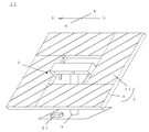
- the power generation panel 2 as a whole has a square shape. That is, on one frame 6, four solar cell panels 5 are arranged in a square shape so as to leave a central portion. By arranging in this way, it is possible to effectively prevent the wind from blowing from the central portion of the power generation panel 2 even when the wind is blowing, and the power generation panel 2 to be shaken or toppled by strong wind.
- the support column 4 is not particularly limited as long as it can support the power generation panel 2 and the gyro mechanism 3, and the thickness and length thereof are not particularly limited. What is necessary is just to prepare a suitable thing according to the magnitude
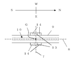
- FIG. 2 is a side view of the heliostat device 1 of FIG. 1 viewed from the back side (east side).
- the power generation panel 2 is in a horizontal state.
- FIG. 3 is a plan view of the vicinity of the cylindrical body of the gyro mechanism.
- the gyro mechanism 3 is connected to a frame 6, and an elevation angle rotation shaft 7 having an east-west direction as an axial direction for rotating the frame 6 (and the power generation panel 2) in the north-south direction, and And an azimuth rotation axis 8 with the north-south direction as the axial direction for rotation in the east-west direction.
- the elevation rotation axis 7 and the azimuth rotation axis 8 are orthogonal to each other. Further, these intersecting points coincide with the center of gravity G of the power generation panel 2 supported by the gyro mechanism 3.
- the conventional pedestal table is not a gyro type, and naturally, the center of the gyro and the center of gravity G do not coincide with each other, and a considerable force is required to rotate the power generation panel.
- the power generation panel 2 can be easily rotated with a much smaller force than before, and the angle of the solar cell panel 5 can be adjusted with less power.
- a cylindrical body 9 is provided so that its longitudinal direction is along the azimuth rotation axis 8. Further, an azimuth rotary shaft 10 is provided that penetrates the cylinder 9 in the longitudinal direction and is positioned on the azimuth rotary shaft 8. Furthermore, a connecting cover 11 that connects both ends of the penetrating azimuth rotating shaft 10 is provided, and a connecting arm 12 that connects to the frame 6 is provided at the tip of the connecting cover 11. .
- the connection cover 11 should just be able to rotate in the east-west direction by making the azimuth rotation shaft 10 into a rotating shaft. For example, the two are welded to each other and are completely connected to each other, and the connecting cover 11 can be rotated along with the axial rotation of the azimuth rotating shaft 10 itself.
- the outer shape of the cylindrical body 9 may be a prismatic shape or a cylindrical shape. Any material can be used as long as the azimuth rotating shaft 10 can penetrate the inside thereof.
- the connecting cover 11 has a U-shape, and includes a top plate 15 and two side plates 16 joined so as to sandwich the top plate 15. Side plates 16 are connected to both ends of the azimuth shaft 10 penetrating the cylinder 9. When the power generation panel 2 is in a horizontal state, the top plate 15 is positioned above the cylindrical mold 9.
- the connecting arm 12 is connected to the side plate 16 opposite to the side joined to the top plate 15, and the frame 6 is connected to the connecting arm 12 as described above. With such a configuration, the cylindrical body 9, the azimuth rotation shaft 10, the connection cover 11, the connection arm 12, and the frame 6 are integrated.
- the support 4 is provided with a bearing 14, and the pair of elevation rotation shafts 13 are supported by the bearing 14 so as to be rotatable.
- connection cover 11 can be rotated in the east-west direction with the azimuth rotation shaft 10 as the rotation axis, and the connection cover 11 is connected to the frame 6 and further to the solar cell panel 5 via the connection arm 12. So that they can be rotated together. That is, the power generation panel 2 can be rotated in the east-west direction, and the east-west angle of the panel surface of the solar cell panel 5 can be adjusted.
- the cylinder body 9 can be rotated in the north-south direction with the elevation angle rotation shaft 13 as a rotation axis.
- the cylinder body 9 includes an azimuth rotation shaft 10 and a connection cover 11 passing therethrough. Since it is connected to the frame 6 and further to the solar cell panel 5 via the connecting arm 12, they can be rotated integrally. That is, the power generation panel 2 can be rotated in the north-south direction, and the angle of the panel surface of the solar cell panel 5 in the north-south direction can be adjusted.
- the power generation panel 2 can be easily and freely rotated in the east-west direction and the north-south direction on the support column 4, and the angle of the panel surface of the solar cell panel 5 can be adjusted with a high degree of freedom. it can.
- the angle of the panel surface of the solar cell panel 5 can be freely adjusted as compared with the conventional graduation table type, and the occurrence of shadow interference can be further prevented.
- a gyro-type heliostat device of the present invention having the power generation panel of FIG. 1 and a conventional graduation table type as shown in FIG. 12 having the same shape of the power generation panel.
- the angle adjustment in the east-west direction can actually rotate only horizontally. That is, the lower side (and the upper side) of the power generation panel can only rotate so as to be always parallel to the ground (the height positions at both ends of the lower side are always the same).
- the entire power generation panel can be rotated in the east-west direction after adjusting the angle in the north-south direction. That is, rotation adjustment can be performed so that the height positions of both ends of the lower side (and upper side) of the power generation panel are different from each other, and rotation adjustment can be performed so that the height positions are the same.
- the gyro type as in the present invention can adjust the angle of the power generation panel with a higher degree of freedom than the conventional graduation table type. Therefore, even if the distance between the heliostat devices has conventionally caused shadow interference, the gyro type as in the present invention can prevent the occurrence of shadow interference depending on the angle adjustment. That is, heliostat devices can be arranged closer to each other, and the power generation efficiency per unit land area can be improved.
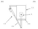
- the gyro mechanism 3 further includes an elevation angle adjustment actuator 17 and an azimuth angle adjustment actuator 18.
- the means for rotating the power generation panel 2 in the gyro mechanism 3 as described above is not particularly limited, but if it is an actuator, it can be simply rotated by a motor drive.
- the arrangement position of the elevation angle adjusting actuator 17 the position shown in FIG.
- the column 4 is attached so as to connect the lower surface side of the cylindrical body 9.
- the south side of the cylindrical body 9 can be pushed and the power generation panel 2 can be rotated to the north side.
- the arm 19 contracts, the south side of the cylindrical body 9 is pulled, and the power generation panel 2 can be rotated to the south side.
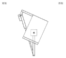
- FIG. 4 shows an example of the arrangement position of the azimuth angle adjusting actuator 18.
- FIG. 4 is a schematic view of the azimuth adjusting actuator 18 as seen from the north side.
- An azimuth angle adjusting actuator 18 is attached so as to connect a portion protruding east from the connection cover 11 and a portion protruding from the lower surface of the cylindrical body 9.
- the connecting cover 11 is inclined to the west side, and the power generation panel 2 can be rotated to the west side.
- FIG. 5 shows a state when rotating from the state of FIG. 4 to the west side.
- connection cover 11 is inclined to the east side, and the power generation panel 2 can be rotated to the east side.
- the connection cover 11 is inclined to the east side, and the power generation panel 2 can be rotated to the east side.
- the truss structure is taken, so that wind resistance can be obtained.
- each actuator can be appropriately arranged so as to obtain the required maximum inclination angle.
- the storage battery 21 can be arrange
- the rotation control of the power generation panel 2 can be performed with an extremely small force. Therefore, it is possible to suppress power consumption required for rotational driving of the power generation panel 2. Therefore, unlike the conventional device, the gyro mechanism 3 is sufficiently operated by the storage battery 21 provided in each heliostat device without drawing a large-scale wiring for supplying electric power from the outside, and the power generation panel 2 The angle of the panel surface of the solar cell panel 5 can be adjusted. In terms of power supply, it becomes independent. The cost and maintenance required for installing the wiring can be omitted, which is simple.
- FIG. 6 an example of the heliostat apparatus of another aspect is shown.
- an auxiliary solar cell panel 22 is further provided. Here, it is arranged on the connecting cover 11.
- the electric power obtained by the auxiliary solar cell panel 22 can be stored in the storage battery 21. For this reason, it can be made more independent.
- size, etc. of the auxiliary solar cell panel 22 are not specifically limited, What is necessary is just enough to charge the storage battery 21.
- the solar cell panel (or power generation panel) is a fixed type
- the solar tracking type is provided with a heliostat device
- the type is a graticule type
- each heliostat device can be arranged closer to the scale table type device, and as a whole, the required area is about the same as that of the fixed type, that is, 1 .3 or so.
- the gyro-type heliostat device of the present invention can have the same installation area as that of the fixed type, and can obtain solar energy of the same level as the pedestal table type device. For this reason, power generation efficiency can be improved compared with the past. Moreover, since the center of the gyro and the center of gravity of the power generation panel coincide with each other, rotation control can be easily performed with extremely small force.
- FIG. 13 shows an example of a heliostat device provided with a reflecting mirror.
- a heliostat device 23 of FIG. 13 four rectangular reflecting mirrors 24 are provided.
- Other configurations such as the configuration of the frame, the gyro mechanism, the support column, and the like can be the same.
- the reflecting mirror 24 can be freely rotated in the east-west direction and the north-south direction, and the angle of the reflecting surface can be appropriately adjusted.
- substantially the same effects can be obtained, for example, the force required for rotation is small, the degree of freedom of rotation control is high, and the occurrence of shadow interference can be suppressed as compared to the conventional case.
- a plurality of heliostat devices as shown in FIG. 1 are arranged on the ground.
- position is not specifically limited, It can determine suitably according to the land area which can be installed, and the solar energy amount which is due to collect.
- an arrangement position is not specifically limited, For example, it can arrange
- a gyro mechanism including a frame, a cylindrical body, a column, an actuator, a storage battery, an auxiliary solar cell, etc.
- a battery panel or the like By arranging a battery panel or the like, the above-described effects can be obtained.
- a wind countermeasure when a plurality of solar cell panels are arranged on one frame as shown in FIG. 1, it is preferable to arrange them in a square shape and provide a space in the central portion.
- the sun supported by the frame is rotated by rotating the frame and the solar cell panel integrally in the north-south direction using the elevation rotation axis as the rotation axis.
- the north-south angle of the panel surface of the battery panel can be adjusted.
- the angle of the east-west direction of the panel surface of the solar cell panel supported by the frame is adjusted by rotating the frame and the solar cell panel integrally in the east-west direction with the azimuth rotation axis as the rotation axis. Can do.
- connection cover and the connection arm are arranged with the azimuth rotation shaft on the azimuth rotation axis as the rotation axis.
- the frame can be rotated integrally in the east-west direction.
- the cylindrical body, the azimuth rotation shaft, the connection cover, the connection arm, and the frame can be integrally rotated in the north-south direction using the pair of elevation rotation shafts on the elevation rotation shaft as the rotation axes. it can.
- the power generation panel is rotated, and the angle of the panel surface of the solar cell panel (the angle of the power generation panel) can be easily adjusted with a small force.
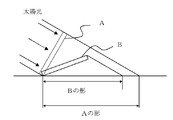
- FIG. 7 shows a state where the power generation panel is installed at a different angle with respect to sunlight. This is a state when A is installed perpendicular to sunlight, and B is a state when installed at an angle lower than the state of A.
- the amount of sunlight radiated to the power generation panel is greater when the power is A.
- the area of the shadow on the ground is also larger when A.
- the power generation panel oriented perpendicular to the sunlight may cause shadows on other panel surfaces.
- the positions of the heliostats are separated from each other, the land use efficiency decreases, resulting in a decrease in power generation efficiency.
- the generation of shadow interference is determined depending on whether or not the occurrence of shadow interference, and the power generation panel is adjusted while adjusting the angle of the power generation panel. I do. More specifically, first, when the power generation panel is oriented perpendicular to the sunlight, the angle of the power generation panel is adjusted to be perpendicular to the sunlight in the time zone when no shadow is generated on the other panel surface. .
- the angle of the power generation panel is adjusted under two conditions.
- the first is to adjust the power generation panel so that the shadow of the power generation panel deviates from the other panel surface and is generated on the ground.
- the second is to adjust based on the size of the area of the shadow generated on the ground.
- more sunlight energy can be recovered when the light is directed perpendicular to sunlight, and the shadow on the ground at that time is also larger. That is, the angle is adjusted in consideration of the size of the shadow on the ground while satisfying the first condition. For example, it is preferable to adjust the angle so that the shadow becomes larger.
- the control method is to reduce the area where sunlight hits the ground while preventing shadow interference, but this control method also takes into account the size of the shadow area on the ground. The inventor found for the first time.
- FIG. 8 shows the relationship of the rotation axes of the gyro type heliostat device. If the x, y, and z axes are taken in the east, north, and zenith directions, respectively, as shown in FIG. 8, in the gyro type, the rotation axis in the north-south direction becomes the x axis (elevation angle rotation axis), and y ′ after rotation of the x axis. The axis becomes the rotation axis in the east-west direction (azimuth rotation axis).
- FIG. 9 is an explanatory diagram showing an adjustment method for preventing shadow interference.
- the shape of the solar cell panel mounted on the heliostat device is square, and this is rotated about two axes as described above, and the four corners at that time are defined as positions Pa, Pb, Pc, Pd ( (P1a, P1b, P1c, P1d on the front panel, P2a, P2b, P2c, P2d on the rear panel).
- the position vectors of the four corners with the center of the solar cell panel as the origin O (0, 0, 0) are Pa, Pb, Pc, and Pd.
- the vectors Pa and Pd and the z components of the vectors Pb and Pc do not have the same value except in the south-central time. Therefore, except for the south-central time, Zp1a ⁇ Zp1b, Zp1c ⁇ Zp1d 2), Also, Zp2a ⁇ Zp2b, Zp2c ⁇ Zp2d (Formula 3) It has become.
- the y-axis is not parallel to the ground due to the x-axis rotation (the y′-axis, that is, the y-axis having an angle corresponding to the x-axis rotation with respect to the ground) is the rotation axis in the east-west direction. Therefore, if the north-south axis has a certain angle (zero at the north and south poles, and usually always has a certain finite angle), the y ' The line segment P1aP1b and the line segment P1cP1d do not become parallel to the ground by the rotation. In addition, if the solar cell panels in the rear row also take the same rotation angle with respect to these line segments, the shadow generated for a certain solar direction vector (sunlight) will not interfere with the solar cell panel behind. It can always take a certain value.
- the gyro type can be controlled so as not to cause shadow interference as shown in FIG. According to the control for avoiding such shadow interference, it is possible to reduce the portion of the land that is not exposed to the sun, so that the amount of photovoltaic power generation per site can be increased.
- FIG. 10 shows an example of the solar fluctuation curve.
- FIG. 10 is a plot of the movement of the sun during the spring equinox, winter solstice, and summer solstice. The sun moves along such a curve. For this reason, the position (altitude, azimuth angle) of the sun at a certain time can be specified, and the adjustment angle of the power generation panel that is perpendicular to the sunlight can be obtained in advance.
- the arrangement interval between the respective heliostat devices is determined, it can be easily determined whether or not shadow interference occurs at that time. If no shadow interference occurs, the angle is controlled so as to be perpendicular to sunlight as described above.
- shadow interference occurs, adjustment is performed so as to satisfy the above two conditions.
- a value satisfying the above-described expression 1, expression 1 ′ (z component), etc. is obtained so that the shadow interference disappears.
- the sun moves according to this fluctuation curve, and therefore the adjustment angle of the power generation panel that is perpendicular to the sunlight is also known in advance.
- the angle can be adjusted to be perpendicular to the sunlight at the sun position (altitude, azimuth angle) at 10 am on that day. If adjustment is made in consideration of the solar fluctuation curve in this way, it is not necessary to move the power generation panel largely and wastefully to eliminate the shadow interference, and it is possible to keep a large shadow area on the ground. Therefore, not the power generation panel but the amount of sun hitting the ground can be suppressed, and solar energy can be recovered efficiently.
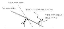
- FIG. 11 shows an example of the presence or absence of shadow interference at 8:00 am and 10:00 am.
- the boundary of sunlight and the shadow formed by the upper part of the power generation panel in the front row are drawn. If the power generation panel of each heliostat device is directed perpendicular to the sunlight at 8:00 am, the front panel panel surface causes a shadow on the other panel surface in the rear column. However, if the angle of the power generation panel of each heliostat device is adjusted to an angle that is perpendicular to the sunlight at 10 am on that day, shadow interference can be prevented at 8 am .
- the degree to which the angle is adjusted by shifting to the south / central time side may be determined each time, and is not particularly limited.
- the present invention is not limited to the above embodiment.
- the above-described embodiment is an exemplification, and the present invention has substantially the same configuration as the technical idea described in the claims of the present invention, and any device that exhibits the same function and effect is the present invention. It is included in the technical scope of the invention.
Landscapes
- Engineering & Computer Science (AREA)
- Life Sciences & Earth Sciences (AREA)
- Sustainable Development (AREA)
- Physics & Mathematics (AREA)
- Sustainable Energy (AREA)
- Thermal Sciences (AREA)
- Chemical & Material Sciences (AREA)
- Combustion & Propulsion (AREA)
- Mechanical Engineering (AREA)
- General Engineering & Computer Science (AREA)
- Photovoltaic Devices (AREA)
Abstract
La présente invention concerne un appareil héliostat comportant : un cadre qui soutient un miroir réfléchissant ou un panneau de cellules solaires ; un mécanisme gyroscopique qui comporte un arbre rotatif à angle d'élévation pour faire tourner le cadre dans une direction nord-sud et comporte un arbre rotatif à angle azimutal pour faire tourner le cadre dans une direction est-ouest, les arbres rotatifs étant mutuellement orthogonaux ; et une colonne de support qui soutient le cadre par l'intermédiaire du mécanisme gyroscopique. Le cadre, le miroir réfléchissant, etc. sont mis en rotation de façon intégrée, dans la direction nord-sud, autour de l'arbre rotatif à angle d'élévation, en tant qu'axe de rotation, de façon à ajuster l'angle de la surface réfléchissante, etc. du miroir réfléchissant dans la direction nord-sud. Le cadre, le miroir réfléchissant, etc. sont mis en rotation de façon intégrée, dans la direction ouest-est, autour de l'arbre rotatif à angle azimutal, en tant qu'axe de rotation, de façon à ajuster l'angle de la surface réfléchissante, etc., du miroir réfléchissant dans la direction ouest-est. Le centre de gravité d'un panneau de génération d'énergie coïncide avec le point d'intersection auquel l'arbre rotatif à angle d'élévation et l'arbre rotatif à angle azimutal du mécanisme gyroscopique sont mutuellement orthogonaux. Par conséquent, l'invention concerne un appareil d'héliostat qui est d'un type configuré pour suivre le mouvement du soleil et qui peut obtenir de l'énergie solaire plus efficacement que les produits classiques, tout en causant rarement une interférence d'ombrage, même lorsque l'intervalle d'agencement est étroit.
Priority Applications (3)
| Application Number | Priority Date | Filing Date | Title |
|---|---|---|---|
| US16/312,767 US20190165721A1 (en) | 2016-06-24 | 2017-06-22 | Heliostat apparatus and solar power generating method |
| CN201780039136.5A CN109690208A (zh) | 2016-06-24 | 2017-06-22 | 定日镜装置及太阳能发电方法 |
| EP17815492.8A EP3477219A4 (fr) | 2016-06-24 | 2017-06-22 | Appareil d'héliostat et procédé de génération d'énergie solaire |
Applications Claiming Priority (4)
| Application Number | Priority Date | Filing Date | Title |
|---|---|---|---|
| JP2016-125265 | 2016-06-24 | ||
| JP2016125265A JP2017227408A (ja) | 2016-06-24 | 2016-06-24 | ヘリオスタット装置 |
| JP2016125269A JP2017229195A (ja) | 2016-06-24 | 2016-06-24 | 太陽光発電方法 |
| JP2016-125269 | 2016-06-24 |
Publications (1)
| Publication Number | Publication Date |
|---|---|
| WO2017222026A1 true WO2017222026A1 (fr) | 2017-12-28 |
Family
ID=60783207
Family Applications (1)
| Application Number | Title | Priority Date | Filing Date |
|---|---|---|---|
| PCT/JP2017/023091 WO2017222026A1 (fr) | 2016-06-24 | 2017-06-22 | Appareil d'héliostat et procédé de génération d'énergie solaire |
Country Status (4)
| Country | Link |
|---|---|
| US (1) | US20190165721A1 (fr) |
| EP (1) | EP3477219A4 (fr) |
| CN (1) | CN109690208A (fr) |
| WO (1) | WO2017222026A1 (fr) |
Families Citing this family (3)
| Publication number | Priority date | Publication date | Assignee | Title |
|---|---|---|---|---|
| AU2017323869A1 (en) * | 2016-09-07 | 2019-03-28 | C I Corporation Pty Ltd | A dual axis solar tracker assembly |
| JP6535402B1 (ja) | 2018-05-31 | 2019-06-26 | 株式会社SolarFlame | 太陽追尾装置 |
| CN110414059B (zh) * | 2019-06-28 | 2020-12-01 | 浙江大学 | 塔式太阳能热电站中平面定日镜的辐射能密度模拟方法 |
Citations (12)
| Publication number | Priority date | Publication date | Assignee | Title |
|---|---|---|---|---|
| US4586488A (en) * | 1983-12-15 | 1986-05-06 | Noto Vincent H | Reflective solar tracking system |
| JP2004235284A (ja) * | 2003-01-29 | 2004-08-19 | Daido Steel Co Ltd | 集光式太陽光発電装置の太陽電池パネルの設置方法 |
| DE102008023549A1 (de) * | 2008-05-14 | 2009-11-19 | Dieckmann, Klaus E., Dipl.-Ing. | Kardanisch gelagerte Prozessfläche |
| JP3158018U (ja) * | 2009-12-08 | 2010-03-11 | 干布太陽能股▲ふん▼有限公司 | ソーラーエネルギー太陽追尾装置構造 |
| JP2010205762A (ja) * | 2009-02-27 | 2010-09-16 | Mitsubishi Electric Corp | 追尾型太陽光発電装置 |
| JP2011066030A (ja) * | 2009-09-15 | 2011-03-31 | Mitsubishi Electric Corp | 追尾型太陽光発電システム |
| WO2013129177A1 (fr) * | 2012-02-29 | 2013-09-06 | 三菱重工業株式会社 | Dispositif de collecte de lumière, équipement de collecte de chaleur équipé de celui-ci, et équipement de génération d'énergie thermique solaire |
| JP2013225650A (ja) * | 2012-04-23 | 2013-10-31 | Topper Sun Energy Technology Co Ltd | 太陽光発電機ユニットの自動太陽追尾調整コントロール装置 |
| WO2014071683A1 (fr) * | 2012-11-06 | 2014-05-15 | Liu Jianzhong | Support de suivi à arbre double |
| JP2014527794A (ja) * | 2011-08-15 | 2014-10-16 | モーガン ソーラー インコーポレーテッド | 自己安定型の太陽光追尾装置 |
| WO2015037230A1 (fr) * | 2013-09-10 | 2015-03-19 | 株式会社SolarFlame | Dispositif d'héliostat, dispositif de collecte thermique solaire, et dispositif photovoltaïque de concentration solaire |
| JP2017028907A (ja) * | 2015-07-24 | 2017-02-02 | 裕 玉浦 | 追尾型太陽光発電装置とその制御方法 |
Family Cites Families (7)
| Publication number | Priority date | Publication date | Assignee | Title |
|---|---|---|---|---|
| WO2005098327A1 (fr) * | 2004-03-30 | 2005-10-20 | Solar Hytech Co., Ltd. | Heliostat et procede de controle de celui-ci |
| WO2008084121A1 (fr) * | 2006-12-29 | 2008-07-17 | Hispanotracker, S.L. | Suiveur solaire bidirectionnel |
| CN101236287A (zh) * | 2008-02-26 | 2008-08-06 | 苏建国 | 定日镜装置 |
| CN101877560B (zh) * | 2010-04-02 | 2012-07-04 | 刘建中 | 自动跟踪太阳光装置 |
| CN102563919B (zh) * | 2010-12-28 | 2013-12-11 | 北京应天阳光太阳能技术有限公司 | 一种采用自旋仰角跟踪方式的太阳炉 |
| CN103455044B (zh) * | 2012-05-29 | 2016-12-14 | 太阳光电能源科技股份有限公司 | 太阳能发电机组的自动追日调控装置 |
| JP2015181324A (ja) * | 2013-08-26 | 2015-10-15 | Thk株式会社 | 太陽光追尾装置 |
-
2017
- 2017-06-22 CN CN201780039136.5A patent/CN109690208A/zh active Pending
- 2017-06-22 WO PCT/JP2017/023091 patent/WO2017222026A1/fr unknown
- 2017-06-22 US US16/312,767 patent/US20190165721A1/en not_active Abandoned
- 2017-06-22 EP EP17815492.8A patent/EP3477219A4/fr not_active Withdrawn
Patent Citations (12)
| Publication number | Priority date | Publication date | Assignee | Title |
|---|---|---|---|---|
| US4586488A (en) * | 1983-12-15 | 1986-05-06 | Noto Vincent H | Reflective solar tracking system |
| JP2004235284A (ja) * | 2003-01-29 | 2004-08-19 | Daido Steel Co Ltd | 集光式太陽光発電装置の太陽電池パネルの設置方法 |
| DE102008023549A1 (de) * | 2008-05-14 | 2009-11-19 | Dieckmann, Klaus E., Dipl.-Ing. | Kardanisch gelagerte Prozessfläche |
| JP2010205762A (ja) * | 2009-02-27 | 2010-09-16 | Mitsubishi Electric Corp | 追尾型太陽光発電装置 |
| JP2011066030A (ja) * | 2009-09-15 | 2011-03-31 | Mitsubishi Electric Corp | 追尾型太陽光発電システム |
| JP3158018U (ja) * | 2009-12-08 | 2010-03-11 | 干布太陽能股▲ふん▼有限公司 | ソーラーエネルギー太陽追尾装置構造 |
| JP2014527794A (ja) * | 2011-08-15 | 2014-10-16 | モーガン ソーラー インコーポレーテッド | 自己安定型の太陽光追尾装置 |
| WO2013129177A1 (fr) * | 2012-02-29 | 2013-09-06 | 三菱重工業株式会社 | Dispositif de collecte de lumière, équipement de collecte de chaleur équipé de celui-ci, et équipement de génération d'énergie thermique solaire |
| JP2013225650A (ja) * | 2012-04-23 | 2013-10-31 | Topper Sun Energy Technology Co Ltd | 太陽光発電機ユニットの自動太陽追尾調整コントロール装置 |
| WO2014071683A1 (fr) * | 2012-11-06 | 2014-05-15 | Liu Jianzhong | Support de suivi à arbre double |
| WO2015037230A1 (fr) * | 2013-09-10 | 2015-03-19 | 株式会社SolarFlame | Dispositif d'héliostat, dispositif de collecte thermique solaire, et dispositif photovoltaïque de concentration solaire |
| JP2017028907A (ja) * | 2015-07-24 | 2017-02-02 | 裕 玉浦 | 追尾型太陽光発電装置とその制御方法 |
Non-Patent Citations (1)
| Title |
|---|
| See also references of EP3477219A4 * |
Also Published As
| Publication number | Publication date |
|---|---|
| EP3477219A1 (fr) | 2019-05-01 |
| EP3477219A4 (fr) | 2020-01-29 |
| CN109690208A (zh) | 2019-04-26 |
| US20190165721A1 (en) | 2019-05-30 |
Similar Documents
| Publication | Publication Date | Title |
|---|---|---|
| US10008977B2 (en) | Heliostat apparatus and solar heat collecting apparatus and concentrating photovoltaic apparatus | |
| JP2019047623A (ja) | 太陽光発電方法 | |
| WO2015037230A1 (fr) | Dispositif d'héliostat, dispositif de collecte thermique solaire, et dispositif photovoltaïque de concentration solaire | |
| CA2731583A1 (fr) | Systeme de poursuite solaire photovoltaique | |
| WO2017222026A1 (fr) | Appareil d'héliostat et procédé de génération d'énergie solaire | |
| JP2010205762A (ja) | 追尾型太陽光発電装置 | |
| CN103149947A (zh) | 一种带反阴影跟踪的太阳能跟踪方法 | |
| CN109302136A (zh) | 一种太阳能追踪系统 | |
| JP2012246651A (ja) | パネル組立体の架台、追尾型太陽光発電装置、及び追尾型太陽光発電システム | |
| KR20190115436A (ko) | 계절에 따라 자동으로 각도가 조절되는 태양광발전 장치 | |
| JP6342632B2 (ja) | 太陽光集光発電装置 | |
| JP2009266890A (ja) | 追尾集光型太陽電池装置 | |
| KR101065055B1 (ko) | 태양광 추적장치 | |
| JP5576839B2 (ja) | 太陽追尾装置 | |
| JP2017227408A (ja) | ヘリオスタット装置 | |
| JP2013172145A (ja) | 追尾型太陽光発電装置 | |
| JP2017229195A (ja) | 太陽光発電方法 | |
| JP3156066U (ja) | 可動庇 | |
| JP2013162038A (ja) | 集光式太陽光発電システム | |
| JP2017028907A (ja) | 追尾型太陽光発電装置とその制御方法 | |
| CN102638194A (zh) | 一种太阳能三轴并联跟踪器 | |
| CN203070103U (zh) | 一种简化双轴联动型太阳能光伏发电系统 | |
| KR20100066065A (ko) | 태양광 위치 추적 발전 장치 | |
| KR101647566B1 (ko) | 태양 추적식 태양광 발전장치 | |
| KR100767704B1 (ko) | 태양추적형 태양광 발전장치 |
Legal Events
| Date | Code | Title | Description |
|---|---|---|---|
| 121 | Ep: the epo has been informed by wipo that ep was designated in this application |
Ref document number: 17815492 Country of ref document: EP Kind code of ref document: A1 |
|
| NENP | Non-entry into the national phase |
Ref country code: DE |
|
| ENP | Entry into the national phase |
Ref document number: 2017815492 Country of ref document: EP Effective date: 20190124 |