WO2017221971A1 - タービン、ガスタービン - Google Patents
タービン、ガスタービン Download PDFInfo
- Publication number
- WO2017221971A1 WO2017221971A1 PCT/JP2017/022821 JP2017022821W WO2017221971A1 WO 2017221971 A1 WO2017221971 A1 WO 2017221971A1 JP 2017022821 W JP2017022821 W JP 2017022821W WO 2017221971 A1 WO2017221971 A1 WO 2017221971A1
- Authority
- WO
- WIPO (PCT)
- Prior art keywords
- turbine
- inclined surface
- circumferential direction
- inner cylinder
- axis
- Prior art date
- Legal status (The legal status is an assumption and is not a legal conclusion. Google has not performed a legal analysis and makes no representation as to the accuracy of the status listed.)
- Ceased
Links
Images




Classifications
-
- F—MECHANICAL ENGINEERING; LIGHTING; HEATING; WEAPONS; BLASTING
- F01—MACHINES OR ENGINES IN GENERAL; ENGINE PLANTS IN GENERAL; STEAM ENGINES
- F01D—NON-POSITIVE DISPLACEMENT MACHINES OR ENGINES, e.g. STEAM TURBINES
- F01D25/00—Component parts, details, or accessories, not provided for in, or of interest apart from, other groups
- F01D25/24—Casings; Casing parts, e.g. diaphragms, casing fastenings
-
- F—MECHANICAL ENGINEERING; LIGHTING; HEATING; WEAPONS; BLASTING
- F01—MACHINES OR ENGINES IN GENERAL; ENGINE PLANTS IN GENERAL; STEAM ENGINES
- F01D—NON-POSITIVE DISPLACEMENT MACHINES OR ENGINES, e.g. STEAM TURBINES
- F01D25/00—Component parts, details, or accessories, not provided for in, or of interest apart from, other groups
- F01D25/30—Exhaust heads, chambers, or the like
-
- F—MECHANICAL ENGINEERING; LIGHTING; HEATING; WEAPONS; BLASTING
- F02—COMBUSTION ENGINES; HOT-GAS OR COMBUSTION-PRODUCT ENGINE PLANTS
- F02C—GAS-TURBINE PLANTS; AIR INTAKES FOR JET-PROPULSION PLANTS; CONTROLLING FUEL SUPPLY IN AIR-BREATHING JET-PROPULSION PLANTS
- F02C7/00—Features, components parts, details or accessories, not provided for in, or of interest apart form groups F02C1/00 - F02C6/00; Air intakes for jet-propulsion plants
Definitions
- the present invention relates to a turbine and a gas turbine.
- a typical gas turbine includes a compressor, a combustor, and a turbine.
- the compressor generates high-pressure air by compressing outside air.
- the combustor generates high-temperature and high-pressure combustion gas by mixing fuel with high-pressure air and burning it.
- the turbine is driven by combustion gas.
- a diffuser is provided on the downstream side of the turbine (see Patent Document 1 below). More specifically, the diffuser connects an inner cylinder provided on the inner peripheral side, an outer cylinder that defines an exhaust passage by covering the inner cylinder from the outer peripheral side, and the inner cylinder and the outer cylinder. And a plurality of struts extending in the radial direction of the turbine.
- the exhaust passage gradually increases in diameter from the upstream side to the downstream side in the direction in which the combustion gas flows.
- the flow of the combustion gas discharged from the turbine includes an axial component and a swirl component (swirl component) swirling in the circumferential direction with respect to the axial direction.
- the struts described above extend in the radial direction of the turbine. For this reason, when the flow of exhaust gas passes around the strut, shape resistance is generated by the strut, or flow separation occurs. This may cause a pressure loss in the exhaust gas flow.
- An object of the present invention is to provide a turbine with improved performance and a gas turbine.
- a turbine includes a turbine rotor that extends along an axis and is rotatable toward one side in a circumferential direction of the axis, a turbine casing that covers the turbine rotor from an outer peripheral side, and the turbine A plurality of turbine rotor blades arranged on the outer circumferential surface of the rotor in the circumferential direction of the axis, wherein at least a portion on the other side in the axial direction is curved from one side in the circumferential direction to the other side; A plurality of turbine stationary blades arranged in the circumferential direction and adjacent to the turbine rotor blade on the circumferential surface, and provided on the other axial side of the turbine rotor blade, the axial direction A diffuser that defines an exhaust passage through which exhaust gas flows from one side to the other side, and the diffuser includes an inner cylinder that extends along the axis.
- An outer cylinder that covers the inner cylinder from the outer periphery side, and that defines an exhaust passage between the inner cylinder and the inner cylinder, and is provided in the exhaust passage with a circumferential interval between the inner cylinder and the inner cylinder
- a plurality of struts connected to the outer cylinder and formed with a first surface facing one side in the circumferential direction, the first surface going radially outward from the outer circumferential surface of the inner cylinder It has the 1st inclined surface extended from the circumferential direction one side to the other side.
- the fluid that has passed through the turbine rotor blade often forms a swirl flow as a result of the flow pattern design of the turbine rotor blade and the turbine stationary blade.
- the swirl flow becomes larger than that at rated load.
- the exhaust gas is easily separated from the inner cylinder.
- the vorticity generated by the boundary layer is wound around both sides of the structure to generate a horseshoe vortex having a spiral vortex structure.
- the first inclined surface extends from the circumferential one side to the other side in the radial direction from the outer circumferential surface of the inner cylinder, in the region on the circumferential one side of the first inclined surface.
- a horseshoe vortex containing components extending in the axial direction develops outstandingly.
- the momentum with respect to the fluid (exhaust gas) in the low momentum region in the vicinity of the first inclined surface that is a solid wall surface Therefore, the flow of the exhaust gas is positively attached to the inner cylinder side (radially inside). Thereby, it can suppress that the flow of exhaust gas peels from an inner cylinder.
- the first inclined surface is formed on the strut, a pressure gradient from the outer peripheral side toward the inner cylinder is formed in the vicinity of the inner cylinder. Specifically, the pressure in the region on one side in the circumferential direction of the first inclined surface is higher than the pressure in the region on the other side in the circumferential direction. Thereby, the flow which goes to the other side from the circumferential direction one side arises on the circumferential direction one side of the strut. As a result, pressure can be supplied to the other circumferential side of the strut. Therefore, it can suppress that the flow of exhaust gas peels from the inner cylinder also on the other circumferential side of the strut. As described above, even when the swirl flow is large, it is possible to suppress the pressure loss in the exhaust flow path caused by the separation of the flow from the outer peripheral surface of the inner cylinder.
- the first surface is provided on the radially outer side of the first inclined surface, and is directed from the other side in the circumferential direction toward the one side in the radial direction from the inner side to the outer side. It may have a first outer inclined surface extending in the direction.
- a horseshoe vortex including a component extending in the axial direction is formed in a region on one circumferential side of the first outer inclined surface.
- momentum is added to the exhaust gas flow in the low momentum region in the vicinity of the first inclined surface, which is a solid wall surface, in the region on one side in the circumferential direction of the first outer inclined surface. Therefore, the flow of the exhaust gas is positively attached to the outer cylinder side (radially outer side). That is, it is possible to reduce the possibility of the exhaust gas flow separating from the outer cylinder on one side in the circumferential direction of the first outer inclined surface.
- the first inclined surface is formed on the strut, a pressure gradient from the outer peripheral side toward the inner cylinder is formed in the vicinity of the inner cylinder. Specifically, the pressure in the region on the one side in the circumferential direction of the first outer inclined surface is higher than the pressure in the region on the other side in the circumferential direction. That is, a pressure gradient is formed in which the pressure decreases from one circumferential side of the strut toward the other side. Due to this pressure gradient, the flow of the exhaust gas flows so as to be pressed toward the outer peripheral surface of the inner cylinder.
- the strut is formed with a second surface facing the other circumferential side, and the second surface is directed radially outward from the outer circumferential surface of the inner cylinder. You may have the 2nd inclined surface extended from the circumferential direction one side to the other side.
- the second surface is provided on the radially outer side of the second inclined surface, and moves from the other side in the circumferential direction toward the one side as it goes from the radially inner side to the outer side. It may have a 2nd outside inclined surface extended.
- the second inclined surface may extend from the outer peripheral surface of the inner cylinder to the inner peripheral surface of the outer cylinder.
- the first inclined surface extends from the outer peripheral surface of the inner cylinder to the inner peripheral surface of the outer cylinder.
- the first inclined surface continuously extends without being bent from the outer peripheral surface of the inner cylinder to the inner peripheral surface of the outer cylinder.
- a gas turbine includes a compressor that generates high-pressure air, a combustor that generates high-temperature and high-pressure combustion gas by mixing fuel in the high-pressure air and burning it, and the combustion gas And the turbine according to any one of the above aspects driven by the motor.
- a turbine with improved performance and a gas turbine can be provided.
- a gas turbine 100 includes a compressor 1 that generates high-pressure air, a combustor 3 that generates combustion gas by mixing fuel with high-pressure air, and combustion. And a turbine 2 driven by gas.
- the compressor 1 includes a compressor rotor 11 that extends along the axis Am and a compressor casing 12 that covers the compressor rotor 11 from the outer peripheral side.
- a plurality of compressor blade stages 13 arranged at intervals in the axis Am direction are provided on the outer peripheral surface of the compressor rotor 11.
- Each compressor blade stage 13 has a plurality of compressor blades 14 arranged on the outer peripheral surface of the compressor rotor 11 at intervals in the circumferential direction of the axis Am.
- a plurality of compressor vane stages 15 arranged at intervals in the axis Am direction are provided on the inner peripheral surface of the compressor casing 12.
- the compressor vane stages 15 are alternately arranged in the direction of the axis Am with respect to the compressor rotor stage 13 described above.
- Each compressor stationary blade stage 15 has a plurality of compressor stationary blades 16 arranged on the inner peripheral surface of the compressor casing 12 at intervals in the circumferential direction of the axis Am.
- the combustor 3 is provided between the compressor casing 12 and a turbine casing 22 (described later). High-pressure air generated by the compressor 1 is guided to the combustor 3. A fuel is mixed with this high-pressure air and burned to generate high-temperature and high-pressure combustion gas. The combustion gas flows into the turbine 2 and drives it.
- the turbine 2 includes a turbine rotor 21 extending along the axis Am, a turbine casing 22 that covers the turbine rotor 21 from the outer peripheral side, and a diffuser 4.
- a plurality of turbine rotor blade stages 23 arranged at intervals in the axis Am direction are provided on the outer peripheral surface of the turbine rotor 21.
- Each turbine blade stage 23 has a plurality of turbine blades 24 arranged on the outer peripheral surface of the turbine rotor 21 at intervals in the circumferential direction of the axis Am.
- a plurality of turbine vane stages 25 arranged at intervals in the axis Am direction are provided on the inner peripheral surface of the turbine casing 22.
- the turbine stationary blade stages 25 are alternately arranged in the axis Am direction with respect to the turbine rotor blade stages 23.
- Each turbine stationary blade stage 25 has a plurality of turbine stationary blades 26 arranged on the inner peripheral surface of the turbine casing 22 at intervals in the circumferential direction of the axis Am.
- the compressor rotor 11 and the turbine rotor 21 are integrally connected in the direction of the axis Am to form a gas turbine rotor 91.
- the compressor casing 12 and the turbine casing 22 are integrally connected along the axis Am to form a gas turbine casing 92.
- the gas turbine rotor 91 is integrally rotatable around the axis Am within the gas turbine casing 92.
- the diffuser 4 is provided integrally with the turbine casing 22 (gas turbine casing 92). More specifically, the diffuser 4 includes an inner cylinder 41 extending along the axis Am, an outer cylinder 42 that covers the inner cylinder 41 from the outer peripheral side, and a plurality of first cylinders that connect the inner cylinder 41 and the outer cylinder 42. A strut 43 (strut) and a second strut 44. A space surrounded by the outer peripheral surface 41A of the inner cylinder 41, the inner peripheral surface 42A of the outer cylinder 42, and a pair of first struts 43 adjacent in the circumferential direction is an exhaust passage C through which exhaust gas discharged from the turbine 2 flows. It is said that.
- the inner cylinder 41 of the diffuser 4 extends along the axis Am, and a bearing device (not shown) that rotatably supports the shaft end portion 91A of the gas turbine rotor 91 is provided inside thereof.
- the outer peripheral surface of the inner cylinder 41 is gradually reduced in diameter as it goes from one side to the other side in the axis Am direction.
- the outer cylinder 42 has a cylindrical shape that covers the inner cylinder 41 from the outer peripheral side.
- the inner peripheral surface 42A of the outer cylinder 42 is gradually enlarged in diameter from one side to the other side in the axis Am direction. That is, the space (exhaust flow path C) defined between the outer cylinder 42 and the inner cylinder 41 is its cross-sectional area (when viewed from the axis Am direction) as it goes from one side to the other side in the axis Am direction.
- the cross-sectional area is gradually expanding. Thereby, the kinetic energy of the fluid (exhaust gas) flowing through the exhaust passage C is converted into pressure.
- first strut 43 and a second strut 44 are provided between the inner cylinder 41 and the outer cylinder 42.
- the first strut 43 and the second strut 44 are mainly provided to fix and support the outer cylinder 42 with respect to the inner cylinder 41.
- the first strut 43 faces the final stage located on the most other side in the axis Am direction among the plurality of turbine rotor blade stages 23.
- six first struts 43 are provided that extend radially from the inner cylinder 41 toward the outer peripheral side. These six first struts 43 are arranged at equal intervals in the circumferential direction of the axis Am.
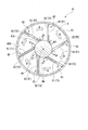
- Each first strut 43 adopts a form (tangential strut) inclined with respect to the tangential direction of the outer peripheral surface 41A of the inner cylinder 41. More specifically, the first strut 43 extends from the other side in the circumferential direction of the axis Am toward one side as it goes from the inner side in the radial direction of the axis Am to the outer side.
- a surface of the first strut 43 facing the one side in the circumferential direction is a first surface S1.
- the surface facing the other circumferential side of the first strut 43 is a second surface S2.
- the first surface S1 and the second surface S2 both extend in the same direction from the radially inner side (the outer peripheral surface of the inner tube 41) to the outer side (the inner peripheral surface of the outer tube 42). .
- the first surface S1 has a first inclined surface T1 that extends from one side in the circumferential direction toward the other side in the radial direction from the inner side to the outer side.
- the second surface S2 has a second inclined surface T2 extending from one side in the circumferential direction toward the other side from the inner side in the radial direction toward the outer side.
- the radially inner ends of the first inclined surface T1 and the second inclined surface T2 are respectively connected to the outer peripheral surface 41A of the inner cylinder 41, and the radially outer ends are respectively connected to the inner peripheral surface 42A of the outer cylinder 42. It is connected.
- the second strut 44 is a member provided to support the load of the outer cylinder 42 with respect to the inner cylinder 41, and is provided mainly for the purpose of distributing the load burden of the first strut 43.
- the second strut 44 is provided at a position spaced from the first strut 43 on the other side in the axis Am direction.
- two second struts 44 extending in a direction away from the outer peripheral surface 41A of the inner cylinder 41 are provided. Each second strut 44 extends parallel to the radial direction of the axis Am.
- the compressor rotor 11 (gas turbine rotor 91) is first rotationally driven by an external drive source. As the compressor rotor 11 rotates, external air is sequentially compressed to generate high-pressure air. This high-pressure air is supplied into the combustor 3 through the compressor casing 12. In the combustor 3, the fuel is mixed with the high-pressure air and burned to generate high-temperature and high-pressure combustion gas. Combustion gas is supplied into the turbine 2 through the turbine casing 22. In the turbine 2, the combustion gas sequentially collides with the turbine rotor blade stage 23 and the turbine stationary blade stage 25, whereby a rotational driving force is given to the turbine rotor 21 (gas turbine rotor 91). This rotational energy is used to drive the generator G connected to the shaft end. The combustion gas that has driven the turbine 2 is discharged to the outside after the pressure (static pressure) is increased as it passes through the exhaust passage C of the diffuser 4 as exhaust gas.
- the pressure static pressure
- the trailing edge side (the portion on the other side in the axis Am direction) of the turbine blade 24 at the final stage is curved from one side in the circumferential direction to the other side, and The turbine rotor 21 rotates from the other side in the circumferential direction toward one side.
- the exhaust gas flowing into the diffuser 4 is given a swirl flow component swirling in the circumferential direction of the axis Am. (The arrow A in FIG.
- FIG. 3 represents the swirling direction of this swirling flow.
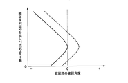
- the horizontal axis represents the turning angle of the swirling flow.
- the plus (+) side of the horizontal axis indicates a state in which the swirling flow is flowing from the other side in the circumferential direction to the one side, and the minus ( ⁇ ) side is a direction in which the swirling flow is from the one side in the circumferential direction toward the other side. It shows the flowing state.
- the vertical axis represents the position coordinates in the radial direction on the first strut 43 with the end on the radially inner side (inner cylinder 41 side) of the first strut 43 as the origin.
- the gas turbine 100 is designed so that the swirl flow becomes as small as possible in order to reduce pressure loss due to interference between the flow and the flow path structure during rated operation.
- the region including the end portion on the inner cylinder 41 side of the first strut 43 and the end portion on the outer cylinder 42 side are defined.
- a swirling flow in the negative direction is generated.
- a positive swirl flow is generated.
- the swirling flow around the first strut 43 shows a distribution as shown by a solid line in FIG. That is, a swirling flow in the negative direction is generated over the entire extension region of the first strut 43.
- the first surface S1 of the first strut 43 has the first inclined surface T1 extending from the one side in the circumferential direction toward the other side from the inner side in the radial direction. That is, this 1st inclined surface T1 is extended so that it may incline in the direction opposite to said turning component as it goes to an outer side from radial inside.
- the vortex V1 as a horseshoe vortex containing the component extended to an axis line Am direction develops outstandingly.
- the horseshoe vortex is a vortex having a spiral tubular structure generated when a vorticity generated by a boundary layer is wound on both sides of the structure when the structure is present in the flow.
- the vortex V1 forms a horseshoe-shaped vortex tube that extends so as to surround the first strut 43 from the other side in the axis Am direction when viewed from the outside in the radial direction.
- the vortex V1 flows along the first inclined surface T1 toward the outer peripheral surface 41A of the inner cylinder 41, and then flows again toward the first inclined surface T1 while being separated from the outer peripheral surface 41A. That is, when viewed from one side in the axis Am direction, the vortex V1 rotates counterclockwise.
- the pressure in the region on one side in the circumferential direction of the first inclined surface T1 becomes higher than the pressure in the region on the other side in the circumferential direction of the second inclined surface T2.
- a pressure gradient is formed in which the pressure decreases from one circumferential side to the other side. Due to this pressure gradient, the exhaust gas flows so as to be pressed toward the outer peripheral surface 41 ⁇ / b> A of the inner cylinder 41. As a result, pressure can be supplied to the other circumferential side of the second inclined surface T2.
- the configuration of the first strut 53 is different from that of the first embodiment. More specifically, the first surface S12 of the first strut 53 includes a first inclined surface T12 positioned relatively radially inward and a first outer inclined surface positioned radially outward of the first inclined surface T12. T13.
- the second surface S22 includes a second inclined surface T14 that is positioned relatively radially inward and a second outer inclined surface T15 that is positioned radially outward of the second inclined surface T14.
- the first inclined surface T12 extends from the outer peripheral surface 41A of the inner cylinder 41 toward the radially outer side. Specifically, the first inclined surface T12 extends from one circumferential side to the other side from the outer circumferential surface 41A of the inner cylinder 41 toward the radially outer side. On the other hand, the first outer inclined surface T13 extends from the other end in the circumferential direction toward one side from the radially outer end of the first inclined surface T12 toward the outer side in the radial direction.
- the second inclined surface T14 extends from the outer peripheral surface 41A of the inner cylinder 41 to the inner peripheral surface 42A of the outer cylinder 42 outward in the radial direction. Specifically, the second inclined surface T14 extends from the one side in the circumferential direction toward the other side from the outer circumferential surface 41A of the inner cylinder 41 toward the radially outer side. On the other hand, the second outer inclined surface T15 extends from the other side in the circumferential direction toward the one side as it goes from the radially outer end of the second inclined surface T14 to the outer side in the radial direction. That is, the first inclined surface T12 and the second inclined surface T14 extend in parallel to each other.
- first outer inclined surface T13 and the second outer inclined surface T15 extend in parallel to each other. Furthermore, in this embodiment, the extension dimension of the first outer inclined surface T13 is smaller than the extension dimension of the first inclined surface T12, and the extension dimension of the second outer inclined surface T15 is the extension of the second inclined surface T14. Smaller than current dimensions.
- the first outer inclined surface T13 is formed. Accordingly, the separation of the flow on the inner peripheral surface 42A of the outer cylinder 42 can also be suppressed. More specifically, a vortex V2 as a horseshoe vortex including a component extending in the direction of the axis Am is formed in a region on one side in the circumferential direction of the first outer inclined surface T13. The vortex V2 flows along the first outer inclined surface T13 toward the inner peripheral surface 42A of the outer cylinder 42, and then flows again toward the first outer inclined surface T13 while being separated from the inner peripheral surface 42A. .
- the vortex V2 when viewed from one side in the direction of the axis Am, the vortex V2 is turning clockwise. Since the vortex V2 is formed, momentum is added to the boundary layer formed in the vicinity of the first outer inclined surface T13 in the region on one side in the circumferential direction of the first outer inclined surface T13.
- the gas flow is positively attached to the inner peripheral surface 42 ⁇ / b> A (radially outer side) of the outer cylinder 42. That is, it is possible to reduce the possibility that the exhaust gas flow is separated from the outer cylinder 42 on one side in the circumferential direction of the first outer inclined surface T13.
- the pressure in the region on one side in the circumferential direction of the first outer inclined surface T13 is higher than the pressure in the region on the other side in the circumferential direction of the second outer inclined surface T15.
- the flow which goes to the other side from the circumferential direction one side across the first strut 53 is generated as in the first embodiment. Therefore, it is possible to reduce the possibility of the exhaust gas flow separating from the outer cylinder 42 also on the other circumferential side of the first strut 53. Thereby, the pressure loss in the exhaust flow path C by a flow peeling from the inner peripheral surface of the outer cylinder 42 can be suppressed.
- the component flowing in the relatively radially inner region of the swirling flow swirling in the exhaust flow path C from the other circumferential side to the one side is applied to the second inclined surface T14.
- a flow can be positively attached to the outer peripheral surface 41 ⁇ / b> A of the inner cylinder 41. That is, the separation of the flow on the outer peripheral surface 41A of the inner cylinder 41 can be further suppressed.
- the component flowing in the relatively radially outer region flows from the radially inner side toward the outer side along the second outer inclined surface T15.
- the flow can be positively attached to the inner peripheral surface 42 ⁇ / b> A of the outer cylinder 42. That is, the separation of the flow on the inner peripheral surface 42A of the outer cylinder 42 can be further suppressed.
- the configuration of the first strut 63 is different from the above embodiments. More specifically, in the first strut 63, the second outer inclined surface T15 in the second embodiment is not formed, and the entire second surface S23 extends from the outer peripheral surface of the inner cylinder 41 to the outer cylinder. The second inclined surface T34 extends uniformly over the inner peripheral surface of 42.
- the second inclined surface T34 extends from the outer circumferential surface 41A of the inner cylinder 41 toward the other side in the circumferential direction as it goes radially outward.
- the first inclined surface T12 positioned relatively radially inward and the first inclined surface T12 positioned radially outward of the first inclined surface T12.
- One outer inclined surface T13 is formed. That is, in the radially outer portion of the first strut 63, the dimension in the circumferential direction is set larger than the other portions.
- the outer peripheral surface 41A of the inner cylinder 41 and the inner periphery of the outer cylinder 42 are formed by forming the first inclined surface T12 and the first outer inclined surface T13. Flow separation from the surface 42A can be suppressed.
- the entire second surface S23 is a second inclined surface T34 that extends uniformly, the radial dimension of the first strut 63 is larger in the circumferential direction than the other portions. ing.
- the rigidity of the 1st strut 63 can be raised compared with the structure by which the dimension in the circumferential direction of the 1st strut 63 is made the same over the whole region of radial direction, for example. That is, even when an external force is applied to the first strut 63, the external force can be sufficiently resisted.
- first struts 43 first struts 53, first struts 63
- first struts 53, first struts 63 the configuration in which six first struts 43 (first struts 53, first struts 63) are provided has been described.
- the number of the first struts 43 is not limited depending on the above-described embodiment, and may be appropriately determined according to the design and specifications.
- the configuration in which the second strut 44 is provided on the other side of the first strut 43 in the axis Am direction has been described.
- the second strut 44 is not necessarily provided, and the first strut 43 (first strut 53, first strut). 63) alone may be provided.
- the configuration of the inner cylinder 41 is not limited depending on the embodiment.
- the example in which the inner cylinder 41 is configured to reduce the diameter from one side to the other side in the axis Am direction has been described.
- the inner cylinder 41 is not necessarily configured as described above, and may extend in parallel to the axis Am. Even if it is such a structure, if the outer cylinder 42 is diameter-expanded toward the other side from the one side of the axis Am direction, the function as the diffuser 4 can be exhibited.
- first inclined surface T12 and the first outer inclined surface T13 are connected to each other, and the second inclined surface T14 and the second outer inclined surface T15 are connected to each other.
- another surface extending in the radial direction may be formed between the first inclined surface T12 and the first outer inclined surface T13.
- another surface extending in the radial direction may be formed between the second inclined surface T14 and the second outer inclined surface T15.
- a turbine with improved performance and a gas turbine can be provided.
Landscapes
- Engineering & Computer Science (AREA)
- Mechanical Engineering (AREA)
- General Engineering & Computer Science (AREA)
- Chemical & Material Sciences (AREA)
- Combustion & Propulsion (AREA)
- Supercharger (AREA)
- Structures Of Non-Positive Displacement Pumps (AREA)
Abstract
タービン(2)は、軸線(Am)の周方向一方側に向かって回転可能なタービンロータと(91)、タービンケーシング(92)と、タービンロータ(91)の外周面上で軸線(Am)の周方向に配列され、少なくとも軸線(Am)方向他方側の部分が周方向一方側から他方側に向かって湾曲している複数のタービン動翼(24)と、周方向に配列された複数のタービン静翼(26)と、軸線(Am)方向一方側から他方側に向かって排気ガスが流通する排気流路(C)を画成するディフューザ(4)と、を備える。ディフューザ(4)は、内筒(41)と、内筒(41)との間に排気流路(C)を画成する外筒(42)と、周方向一方側を向く第一面(S1)が形成された複数のストラット(43)と、を有する。第一面(S1)は、内筒(41)の外周面(41A)から径方向外側に向かうにしたがって周方向一方側から他方側に延びる第一傾斜面(T1)を有する。
Description
本発明は、タービン、ガスタービンに関する。
本願は、2016年6月21日に日本に出願された特願2016-122543号について優先権を主張し、その内容をここに援用する。
本願は、2016年6月21日に日本に出願された特願2016-122543号について優先権を主張し、その内容をここに援用する。
一般的なガスタービンは、圧縮機と、燃焼器と、タービンと、を備えている。圧縮機は、外気を圧縮して高圧空気を生成する。燃焼器は、高圧空気に燃料を混合して燃焼させることで高温高圧の燃焼ガスを生成する。タービンは、燃焼ガスによって駆動される。
上記タービンの下流側にはディフューザが設けられることが一般的である(下記特許文献1参照)。より具体的には、ディフューザは、内周側に設けられた内筒と、この内筒を外周側から覆うことで排気流路を画成する外筒と、これら内筒及び外筒を接続し、タービンの径方向に延びる複数のストラットと、を有している。排気流路は、燃焼ガスの流れる方向の上流側から下流側に向かうにしたがって次第に拡径している。これにより、タービンを駆動した燃焼ガス(排気ガス)は、ディフューザを通過することで静圧が上昇した状態となって外部に排出される。
上記タービンの下流側にはディフューザが設けられることが一般的である(下記特許文献1参照)。より具体的には、ディフューザは、内周側に設けられた内筒と、この内筒を外周側から覆うことで排気流路を画成する外筒と、これら内筒及び外筒を接続し、タービンの径方向に延びる複数のストラットと、を有している。排気流路は、燃焼ガスの流れる方向の上流側から下流側に向かうにしたがって次第に拡径している。これにより、タービンを駆動した燃焼ガス(排気ガス)は、ディフューザを通過することで静圧が上昇した状態となって外部に排出される。
ここで、タービンから排出される燃焼ガスの流れには、軸線方向成分と、軸線方向に対する周方向に旋回する旋回流成分(スワール成分)とが含まれている。一方で、上記のストラットは、タービンの径方向に延びている。このため、排気ガスの流れがストラットの周囲を通過する際に、ストラットによって形状抵抗が生じたり、流れの剥離を生じたりする。これにより、排気ガスの流れに圧力損失を生じてしまう虞がある。
本発明は、性能の向上したタービン、及びガスタービンを提供することを目的とする。
本発明の第一の態様に係るタービンは、軸線に沿って延びるとともに、該軸線の周方向一方側に向かって回転可能なタービンロータと、前記タービンロータを外周側から覆うタービンケーシングと、前記タービンロータの外周面上で前記軸線の周方向に配列され、少なくとも前記軸線方向他方側の部分が周方向一方側から他方側に向かって湾曲している複数のタービン動翼と、前記タービンケーシングの内周面上で前記タービン動翼に対して前記軸線方向に隣接して設けられるとともに、周方向に配列された複数のタービン静翼と、前記タービン動翼の軸線方向他方側に設けられ、軸線方向一方側から他方側に向かって排気ガスが流通する排気流路を画成するディフューザと、を備え、前記ディフューザは、前記軸線に沿って延びる内筒と、前記内筒を外周側から覆うとともに、前記内筒との間に前記排気流路を画成する外筒と、前記排気流路内で周方向に間隔をあけて設けられ、前記内筒と前記外筒とを接続するとともに、周方向一方側を向く第一面が形成された複数のストラットと、を有し、前記第一面は、前記内筒の外周面から径方向外側に向かうにしたがって周方向一方側から他方側に延びる第一傾斜面を有する。
ここで、タービン動翼を通過した流体は、タービン動翼及びタービン静翼のフローパターン設計の結果として、旋回流を形成することが多い。また、部分負荷時のように、軸線方向の流速が比較的に小さい場合には、旋回流が定格負荷時に比べて大きくなる。このように旋回流が大きくなれば、排気ガスが内筒から剥離し易くなってしまう。
ここで一般に、流体の流れの中に構造体が存在する場合、構造体の両側に境界層によって生じた渦度が巻き付くことにより、渦管状の渦構造を有する馬蹄渦が生成される。本実施形態では、第一傾斜面が、内筒の外周面から径方向外側に向かうにしたがって周方向一方側から他方側に延びていることから、第一傾斜面の周方向一方側の領域では、軸線方向に延びる成分を含む馬蹄渦が卓越して発達する。このように馬蹄渦が発達することで、第一傾斜面の周方向一方側の領域では、固体壁面である第一傾斜面近傍の低運動量領域中における流体(排気ガス)の流体に対して運動量が付加されるため、排気ガスの流れが内筒側(径方向内側)に積極的に付着するようになる。これにより、排気ガスの流れが内筒から剥離してしまうことを抑制することができる。
加えて、ストラットに第一傾斜面が形成されていることで、内筒の近傍では外周側から内筒に向かう圧力勾配が形成される。具体的には、第一傾斜面の周方向一方側の領域の圧力は、周方向他方側の領域の圧力よりも高くなる。これにより、ストラットの周方向一方側で、周方向一方側から他方側に向かう流れが生じる。その結果、ストラットの周方向他方側に圧力を供給することができる。したがって、ストラットの周方向他方側でも、排気ガスの流れが内筒から剥離してしまうことを抑制できる。
以上のように、旋回流が大きい場合であっても、内筒の外周面から流れが剥離することによって生じる排気流路内での圧力損失を抑制することができる。
ここで一般に、流体の流れの中に構造体が存在する場合、構造体の両側に境界層によって生じた渦度が巻き付くことにより、渦管状の渦構造を有する馬蹄渦が生成される。本実施形態では、第一傾斜面が、内筒の外周面から径方向外側に向かうにしたがって周方向一方側から他方側に延びていることから、第一傾斜面の周方向一方側の領域では、軸線方向に延びる成分を含む馬蹄渦が卓越して発達する。このように馬蹄渦が発達することで、第一傾斜面の周方向一方側の領域では、固体壁面である第一傾斜面近傍の低運動量領域中における流体(排気ガス)の流体に対して運動量が付加されるため、排気ガスの流れが内筒側(径方向内側)に積極的に付着するようになる。これにより、排気ガスの流れが内筒から剥離してしまうことを抑制することができる。
加えて、ストラットに第一傾斜面が形成されていることで、内筒の近傍では外周側から内筒に向かう圧力勾配が形成される。具体的には、第一傾斜面の周方向一方側の領域の圧力は、周方向他方側の領域の圧力よりも高くなる。これにより、ストラットの周方向一方側で、周方向一方側から他方側に向かう流れが生じる。その結果、ストラットの周方向他方側に圧力を供給することができる。したがって、ストラットの周方向他方側でも、排気ガスの流れが内筒から剥離してしまうことを抑制できる。
以上のように、旋回流が大きい場合であっても、内筒の外周面から流れが剥離することによって生じる排気流路内での圧力損失を抑制することができる。
本発明の第二の態様に係るタービンでは、前記第一面は、前記第一傾斜面の径方向外側に設けられ、径方向内側から外側に向かうにしたがって、周方向他方側から一方側に向かって延びる第一外側傾斜面を有してもよい。
この構成によれば、第一外側傾斜面の周方向一方側の領域では、軸線方向に延びる成分を含む馬蹄渦が形成される。この馬蹄渦が形成されることで、第一外側傾斜面の周方向一方側の領域では、固体壁面である第一傾斜面近傍の低運動量領域中における排気ガスの流れに対して運動量が付加されるため、排気ガスの流れが外筒側(径方向外側)に積極的に付着するようになる。すなわち、第一外側傾斜面の周方向一方側で、排気ガスの流れが外筒から剥離する虞を低減することができる。
加えて、ストラットに第一傾斜面が形成されていることで、内筒の近傍では外周側から内筒に向かう圧力勾配が形成される。具体的には、第一外側傾斜面の周方向一方側の領域の圧力は、周方向他方側の領域の圧力よりも高くなる。すなわち、ストラットの周方向一方側から他方側に向かって圧力が減少する圧力勾配が形成される。この圧力勾配により、排気ガスの流れは、内筒の外周面に向かって押し付けられるように流れる。その結果、ストラットの周方向他方側に圧力を供給することができ、ストラットの周方向他方側でも、排気ガスの流れが外筒から剥離する虞を低減することができる。これにより、外筒の内周面から流れが剥離することによる排気流路内での圧力損失を抑制することができる。
加えて、ストラットに第一傾斜面が形成されていることで、内筒の近傍では外周側から内筒に向かう圧力勾配が形成される。具体的には、第一外側傾斜面の周方向一方側の領域の圧力は、周方向他方側の領域の圧力よりも高くなる。すなわち、ストラットの周方向一方側から他方側に向かって圧力が減少する圧力勾配が形成される。この圧力勾配により、排気ガスの流れは、内筒の外周面に向かって押し付けられるように流れる。その結果、ストラットの周方向他方側に圧力を供給することができ、ストラットの周方向他方側でも、排気ガスの流れが外筒から剥離する虞を低減することができる。これにより、外筒の内周面から流れが剥離することによる排気流路内での圧力損失を抑制することができる。
本発明の第三の態様に係るタービンでは、前記ストラットには、周方向他方側を向く第二面が形成され、前記第二面は、前記内筒の外周面から径方向外側に向かうにしたがって周方向一方側から他方側に延びる第二傾斜面を有してもよい。
この構成では、周方向一方側に向かって旋回する旋回流のうち、相対的に径方向内側の領域を流れる成分は、第二傾斜面に沿って径方向外側から内側に向かって流れる。これにより、内筒の外周面に対して積極的に流れを付着させることができる。すなわち、内筒の外周面上における流れの剥離をさらに抑制することができる。
本発明の第四の態様に係るタービンでは、前記第二面は、前記第二傾斜面の径方向外側に設けられ、径方向内側から外側に向かうにしたがって、周方向他方側から一方側に向かって延びる第二外側傾斜面を有してもよい。
この構成では、周方向一方側に向かって旋回する旋回流のうち、相対的に径方向外側の領域を流れる成分は、第二外側傾斜面に沿って径方向内側から外側に向かって流れる。これにより、外筒の内周面に対して積極的に流れを付着させることができる。すなわち、外筒の内周面上における流れの剥離をさらに抑制することができる。
本発明の第五の態様に係るタービンでは、前記第二傾斜面は、前記内筒の外周面から前記外筒の内周面にわたって延びていてもよい。
この構成によれば、第一傾斜面が、内筒の外周面から外筒の内周面にわたって延びている。言い換えると、この第一傾斜面は、内筒の外周面から外筒の内周面にかけて屈曲することなく、連続的に延びている。これにより、例えば第一傾斜面に屈曲部が形成されている構成に比べて、ストラットの剛性を高めることができる。
本発明の第六の態様に係るガスタービンは、高圧空気を生成する圧縮機と、前記高圧空気に燃料を混合させて燃焼させることで高温高圧の燃焼ガスを生成する燃焼器と、前記燃焼ガスによって駆動される上記のいずれか一の態様に係るタービンと、を備える。
この構成によれば、タービンにおける圧力損失が抑制されることで効率的に運転可能なガスタービンを得ることができる。
本発明によれば、性能が向上したタービン、及びガスタービンを提供することができる。
[第一実施形態]
本発明の第一実施形態について、図面を参照して説明する。図1に示すように、本実施形態に係るガスタービン100は、高圧空気を生成する圧縮機1と、高圧空気に燃料を混合して燃焼させることで燃焼ガスを生成する燃焼器3と、燃焼ガスによって駆動されるタービン2と、を備えている。
本発明の第一実施形態について、図面を参照して説明する。図1に示すように、本実施形態に係るガスタービン100は、高圧空気を生成する圧縮機1と、高圧空気に燃料を混合して燃焼させることで燃焼ガスを生成する燃焼器3と、燃焼ガスによって駆動されるタービン2と、を備えている。
圧縮機1は、軸線Amに沿って延びる圧縮機ロータ11と、圧縮機ロータ11を外周側から覆う圧縮機ケーシング12と、を有している。圧縮機ロータ11の外周面には、軸線Am方向に間隔をあけて配列された複数の圧縮機動翼段13が設けられている。各圧縮機動翼段13は、圧縮機ロータ11の外周面上で軸線Amの周方向に間隔をあけて配列された複数の圧縮機動翼14を有している。圧縮機ケーシング12の内周面には、軸線Am方向に間隔をあけて配列された複数の圧縮機静翼段15が設けられている。圧縮機静翼段15は、上記の圧縮機動翼段13に対して軸線Am方向に交互に配列されている。各圧縮機静翼段15は、圧縮機ケーシング12の内周面上で軸線Amの周方向に間隔をあけて配列された複数の圧縮機静翼16を有している。
燃焼器3は、圧縮機ケーシング12とタービンケーシング22(後述)との間に設けられている。燃焼器3には、圧縮機1で生成された高圧空気が導かれる。この高圧空気に燃料を混合し、燃焼させることで、高温高圧の燃焼ガスが生成される。燃焼ガスは、タービン2に流入してこれを駆動する。
タービン2は、軸線Amに沿って延びるタービンロータ21と、タービンロータ21を外周側から覆うタービンケーシング22と、ディフューザ4と、を有している。タービンロータ21の外周面には、軸線Am方向に間隔をあけて配列された複数のタービン動翼段23が設けられている。各タービン動翼段23は、タービンロータ21の外周面上で軸線Amの周方向に間隔をあけて配列された複数のタービン動翼24を有している。タービンケーシング22の内周面には、軸線Am方向に間隔をあけて配列された複数のタービン静翼段25が設けられている。タービン静翼段25は、上記のタービン動翼段23に対して軸線Am方向に交互に配列されている。各タービン静翼段25は、タービンケーシング22の内周面上で軸線Amの周方向に間隔をあけて配列された複数のタービン静翼26を有している。
圧縮機ロータ11とタービンロータ21とは、軸線Am方向に一体に接続されることで、ガスタービンロータ91を形成している。同様に、圧縮機ケーシング12とタービンケーシング22とは、軸線Amに沿って一体に接続されることで、ガスタービンケーシング92を形成している。ガスタービンロータ91は、ガスタービンケーシング92の内部で軸線Am回りに一体に回転可能とされている。
ディフューザ4は、タービンケーシング22(ガスタービンケーシング92)に一体に設けられている。より具体的には、ディフューザ4は、軸線Amに沿って延びる内筒41と、内筒41を外周側から覆う外筒42と、これら内筒41と外筒42とを接続する複数の第一ストラット43(ストラット)、及び第二ストラット44と、を有している。内筒41の外周面41A、外筒42の内周面42A、及び周方向に隣り合う一対の第一ストラット43によって囲まれる空間は、タービン2から排出された排気ガスが流通する排気流路Cとされている。
続いて、図2を参照してディフューザ4の詳細な構成について説明する。ディフューザ4の内筒41は、軸線Amに沿って延びており、その内側には上記のガスタービンロータ91の軸端部91Aを回転可能に支持する軸受装置(図示省略)が設けられている。内筒41の外周面は、軸線Am方向一方側から他方側に向かうにしたがって次第に縮径している。
外筒42は、内筒41を外周側から覆う筒状をなしている。外筒42の内周面42Aは、軸線Am方向一方側から他方側に向かうにしたがって次第に拡径している。すなわち、外筒42と内筒41との間に画成される空間(排気流路C)は、軸線Am方向一方側から他方側に向かうにしたがって、その断面積(軸線Am方向から見た場合の断面積)が次第に拡大している。これにより、排気流路C内を流通する流体(排気ガス)の運動エネルギーは、圧力に変換されるようになっている。
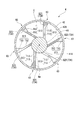
内筒41と外筒42との間には、第一ストラット43、及び第二ストラット44が設けられている。第一ストラット43及び第二ストラット44は、主として外筒42を内筒41に対して固定・支持するために設けられている。第一ストラット43は、複数のタービン動翼段23のうちで軸線Am方向の最も他方側に位置する最終段を臨んでいる。図3に示すように、本実施形態では、内筒41を中心として外周側に向かって放射状に延びる6つの第一ストラット43が設けられている。これら6つの第一ストラット43は、軸線Amの周方向に等間隔をあけて配列されている。
各第一ストラット43は、内筒41の外周面41Aの接線方向に対して傾斜した形式(タンジェンシャルストラット)を採っている。より具体的には、第一ストラット43は、軸線Amの径方向内側から外側に向かうにしたがって、軸線Amの周方向他方側から一方側に向かって延びている。第一ストラット43の周方向一方側を向く面は、第一面S1とされている。一方で、第一ストラット43の周方向他方側を向く面は、第二面S2とされている。本実施形態では、これら第一面S1、及び第二面S2は、いずれも径方向内側(内筒41の外周面)から外側(外筒42の内周面)にわたって同一の方向に延びている。具体的には、第一面S1は、径方向内側から外側に向かうにしたがって周方向一方側から他方側に向かって延びる第一傾斜面T1を有している。第二面S2は、径方向内側から外側に向かうにしたがって周方向一方側から他方側に向かって延びる第二傾斜面T2を有している。第一傾斜面T1及び第二傾斜面T2の径方向内側の端部は、それぞれ内筒41の外周面41Aに接続され、径方向外側の端部は、それぞれ外筒42の内周面42Aに接続されている。
第二ストラット44は、内筒41に対して外筒42の荷重を支持させるために設けられる部材であって、第一ストラット43の荷重負担を分散することを主な目的として設けられる。第二ストラット44は、第一ストラット43から軸線Am方向他方側に離間した位置に設けられている。本実施形態では、内筒41の外周面41Aから互いに離間する方向に延びる2つの第二ストラット44が設けられている。各第二ストラット44は、軸線Amの径方向に対して平行に延びている。
以上のように構成されたガスタービン100を運転するに当たっては、まず外部の駆動源によって圧縮機ロータ11(ガスタービンロータ91)を回転駆動する。圧縮機ロータ11の回転に伴って外部の空気が順次圧縮され、高圧空気が生成される。この高圧空気は、圧縮機ケーシング12を通じて燃焼器3内に供給される。燃焼器3内では、燃料がこの高圧空気に混合されて燃焼し、高温高圧の燃焼ガスが生成される。燃焼ガスはタービンケーシング22を通じてタービン2内に供給される。タービン2内では、タービン動翼段23、及びタービン静翼段25に燃焼ガスが順次衝突することで、タービンロータ21(ガスタービンロータ91)に対して回転駆動力が与えられる。この回転エネルギーは、軸端に連結された発電機Gの駆動に利用される。タービン2を駆動した燃焼ガスは、排気ガスとしてディフューザ4の排気流路Cを通過する際に圧力(静圧)が高められた後、外部に排出される。
続いて、上記のディフューザ4内における排気ガスの挙動について、図3と図4を参照して説明する。上述したように、本実施形態に係るタービン2では、最終段のタービン動翼24の後縁側(軸線Am方向他方側の部分)が周方向一方側から他方側に向かって湾曲しており、かつタービンロータ21は周方向他方側から一方側に向かって回転している。このとき、ディフューザ4内に流入する排気ガスには、軸線Amの周方向に旋回する旋回流成分が付与される。(図3中における矢印Aは、この旋回流の旋回方向を表している。)特に、ガスタービン100が定格運転されている場合、第一ストラット43の周囲における旋回流の旋回角度は、図4のグラフ中の破線で示すような分布を示すことが知られている。
なお、図4のグラフにおいて、横軸は旋回流の旋回角度を表している。横軸のプラス(+)側は、旋回流が周方向他方側から一方側に向かって流れている状態を示し、マイナス(-)側は、旋回流が周方向一方側から他方側に向かって流れている状態を示している。縦軸は第一ストラット43の径方向内側(内筒41側)の端部を原点とする第一ストラット43上における径方向の位置座標を表している。
一般にガスタービン100は、定格運転時において流れと流路内構造物との干渉による圧力損失を小さくするために、旋回流が極力小さくなるように設計されている。本実施形態では、一例として同図中の破線で示すように、ガスタービン100の定格運転時には、第一ストラット43の内筒41側の端部を含む領域、及び外筒42側の端部を含む領域では、マイナス方向の旋回流が生じる。一方で、これら2つの領域に囲まれた領域では、プラス方向の旋回流が生じる。
他方で、ガスタービン100が部分負荷で運転されている状態では、旋回流が大きくなる。この結果、流路内の構造物からの流れの剥離の影響が大きくなる傾向がある。また、これに伴って圧力損失が増加する。本実施形態では、一例として第一ストラット43の周囲における旋回流は、図4中の実線で示すような分布を示している。すなわち、第一ストラット43の延在領域の全体にわたって、マイナス方向の旋回流が生じる。
ここで、上記のように、第一ストラット43の第一面S1は、径方向内側から外側に向かうにしたがって周方向一方側から他方側に延びる第一傾斜面T1を有している。すなわち、この第一傾斜面T1は、径方向内側から外側に向かうにしたがって、上記の旋回成分とは反対の方向に傾斜するように延びている。これにより、第一傾斜面T1の周方向一方側の領域では、軸線Am方向に延びる成分を含む馬蹄渦としての渦V1が卓越して発達する。なお、馬蹄渦とは、流れの中に構造体が存在する場合に構造体の両側に境界層によって生じた渦度が巻き付くことにより生成される渦管状の構造を有する渦である。
この渦V1は、径方向外側から見て、第一ストラット43を軸線Am方向他方側から囲むように延びる馬蹄形の渦管を形成する。また、この渦V1は、第一傾斜面T1に沿って内筒41の外周面41Aに向かって流れた後、外周面41Aから離間しながら、再び第一傾斜面T1に向かうように流れる。すなわち、軸線Am方向一方側から見た場合、渦V1は反時計回りに旋回している。このような渦V1が形成されることで、第一傾斜面T1の周方向一方側の領域では、第一傾斜面T1の近傍で形成される境界層に対して運動量が付加されるため、排気ガスの流れが内筒41の外周面41Aに積極的に付着するようになる。すなわち、第一傾斜面T1の周方向一方側で、排気ガスの流れが内筒41から剥離する虞を低減することができる。
この渦V1は、径方向外側から見て、第一ストラット43を軸線Am方向他方側から囲むように延びる馬蹄形の渦管を形成する。また、この渦V1は、第一傾斜面T1に沿って内筒41の外周面41Aに向かって流れた後、外周面41Aから離間しながら、再び第一傾斜面T1に向かうように流れる。すなわち、軸線Am方向一方側から見た場合、渦V1は反時計回りに旋回している。このような渦V1が形成されることで、第一傾斜面T1の周方向一方側の領域では、第一傾斜面T1の近傍で形成される境界層に対して運動量が付加されるため、排気ガスの流れが内筒41の外周面41Aに積極的に付着するようになる。すなわち、第一傾斜面T1の周方向一方側で、排気ガスの流れが内筒41から剥離する虞を低減することができる。
加えて、上記の渦V1が形成されるため、第一傾斜面T1の周方向一方側の領域の圧力は、第二傾斜面T2の周方向他方側の領域の圧力よりも高くなる。これにより、第一ストラット43の周方向一方側では、周方向一方側から他方側に向かって圧力が減少する圧力勾配が形成される。この圧力勾配により、排気ガスは内筒41の外周面41Aに向かって押し付けられるように流れる。その結果、第二傾斜面T2の周方向他方側に圧力を供給することができる。したがって、第二傾斜面T2の周方向他方側でも、排気ガスの流れが内筒41の外周面41Aから剥離する虞を低減することができる。これにより、排気流路C内での圧力損失を抑制することができる。
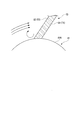
一方で、例えば図6に示すように、第一ストラット43が上記とは反対の方向に傾斜している場合(すなわち、径方向内側から外側に向かうにしたがって、周方向他方側から一方側に傾斜している場合)、内筒41の外周面41A近傍では径方向内側から外側に向かう圧力勾配が形成されてしまう。これにより、外周面41Aの近傍に形成される境界層の安定性が損なわれる虞がある。しかしながら、本実施形態に係るタービン2、及びこれを備えるガスタービン100では、上述の通り、部分負荷時における第一ストラット43周辺での圧力損失を抑制することができる。
特に、上記第一ストラット43のようなタンジェンシャルストラットの形状・姿勢を決定するに当たっては、主に定格運転時における排気ガスの挙動のみを想定することが従来一般的であった。すなわち、一例として軸線Am方向一方側から見て旋回流が周方向他方側から一方側に向かって旋回している場合には、ストラットもこれに対応させて、径方向内側から外側に向かうにしたがって周方向他方側から一方側に向かって傾斜する構成とすることが一般的であった。しかしながら、図4のグラフに基づいて上述したように、ガスタービン100が部分負荷で運転されている場合には、圧力損失の低減を図る上でこのような構成が必ずしも最適ではないことが、本願発明者による新たな知見として得られた。この知見に基づいて、本実施形態では第一ストラット43が上述のような構成を採っている。
[第二実施形態]
次に、本発明の第二実施形態について図7を参照して説明する。なお、上記第一実施形態と同様の構成については同一の符号を付し、詳細な説明を省略する。同図に示すように、本実施形態に係るディフューザ4では、第一ストラット53の構成が上記第一実施形態と相違している。より具体的には、第一ストラット53の第一面S12は、相対的に径方向内側に位置する第一傾斜面T12と、第一傾斜面T12の径方向外側に位置する第一外側傾斜面T13と、を有している。第二面S22は、相対的に径方向内側に位置する第二傾斜面T14と、第二傾斜面T14の径方向外側に位置する第二外側傾斜面T15と、を有している。
次に、本発明の第二実施形態について図7を参照して説明する。なお、上記第一実施形態と同様の構成については同一の符号を付し、詳細な説明を省略する。同図に示すように、本実施形態に係るディフューザ4では、第一ストラット53の構成が上記第一実施形態と相違している。より具体的には、第一ストラット53の第一面S12は、相対的に径方向内側に位置する第一傾斜面T12と、第一傾斜面T12の径方向外側に位置する第一外側傾斜面T13と、を有している。第二面S22は、相対的に径方向内側に位置する第二傾斜面T14と、第二傾斜面T14の径方向外側に位置する第二外側傾斜面T15と、を有している。
第一傾斜面T12は、内筒41の外周面41Aから径方向外側に向かって延びている。具体的には、第一傾斜面T12は、内筒41の外周面41Aから径方向外側に向かうにしたがって、周方向一方側から他方側に向かって延びている。一方で、第一外側傾斜面T13は、第一傾斜面T12の径方向外側の端部から径方向外側に向かうにしたがって、周方向他方側から一方側に向かって延びている。
第二傾斜面T14は、内筒41の外周面41Aから径方向外側に向かって外筒42の内周面42Aまで延びている。具体的には、第二傾斜面T14は、内筒41の外周面41Aから径方向外側に向かうにしたがって、周方向一方側から他方側に向かって延びている。一方で、第二外側傾斜面T15は、第二傾斜面T14の径方向外側の端部から径方向外側に向かうにしたがって、周方向他方側から一方側に向かって延びている。すなわち、上記の第一傾斜面T12と第二傾斜面T14とは互いに平行に延びている。同様に、第一外側傾斜面T13と第二外側傾斜面T15とは互いに平行に延びている。さらに、本実施形態では第一外側傾斜面T13の延在寸法は、第一傾斜面T12の延在寸法よりも小さく、第二外側傾斜面T15の延在寸法は、第二傾斜面T14の延在寸法よりも小さい。
このような構成によれば、第一傾斜面T12が形成されていることによって内筒41の外周面41A上における流れの剥離を抑制できることに加えて、第一外側傾斜面T13が形成されていることによって外筒42の内周面42A上における流れの剥離をも抑制することができる。より具体的には、第一外側傾斜面T13の周方向一方側の領域では、軸線Am方向に延びる成分を含む馬蹄渦としての渦V2が形成される。この渦V2は、第一外側傾斜面T13に沿って外筒42の内周面42Aに向かって流れた後、内周面42Aから離間しながら、再び第一外側傾斜面T13に向かうように流れる。すなわち、軸線Am方向一方側から見た場合、渦V2は時計回りに旋回している。この渦V2が形成されることで、第一外側傾斜面T13の周方向一方側の領域では、第一外側傾斜面T13の近傍で形成される境界層に対して運動量が付加されるため、排気ガスの流れが外筒42の内周面42A(径方向外側)に積極的に付着するようになる。すなわち、第一外側傾斜面T13の周方向一方側で、排気ガスの流れが外筒42から剥離する虞を低減することができる。
加えて、上記の渦V2が形成されるため、第一外側傾斜面T13の周方向一方側の領域の圧力は、第二外側傾斜面T15の周方向他方側の領域の圧力よりも高くなる。これにより、上記第一実施形態と同様に、第一ストラット53を挟んで周方向一方側から他方側に向かう流れが生じる。したがって、第一ストラット53の周方向他方側でも、排気ガスの流れが外筒42から剥離する虞を低減することができる。これにより、外筒42の内周面から流れが剥離することによる排気流路C内での圧力損失を抑制することができる。
さらに、上記の構成では、排気流路C中を、周方向他方側から一方側に向かって旋回する旋回流のうち、相対的に径方向内側の領域を流れる成分は、第二傾斜面T14に沿って径方向外側から内側に向かって流れる。これにより、内筒41の外周面41Aに対して積極的に流れを付着させることができる。すなわち、内筒41の外周面41A上における流れの剥離をさらに抑制することができる。
また、排気流路C中の旋回流のうち、相対的に径方向外側の領域を流れる成分は、第二外側傾斜面T15に沿って径方向内側から外側に向かって流れる。これにより、外筒42の内周面42Aに対して積極的に流れを付着させることができる。すなわち、外筒42の内周面42A上における流れの剥離をさらに抑制することができる。
[第三実施形態]
続いて、本発明の第三実施形態について図8を参照して説明する。なお、上記の各実施形態と同様の構成については同一の符号を付し、詳細な説明を省略する。同図に示すように、本実施形態に係るディフューザ4では、第一ストラット63の構成が上記の各実施形態とは相違している。より具体的には、この第一ストラット63では、上記の第二実施形態における第二外側傾斜面T15が形成されておらず、第二面S23の全体が、内筒41の外周面から外筒42の内周面にわたって一様に延びる第二傾斜面T34とされている。第二傾斜面T34は、内筒41の外周面41Aから径方向外側に向かうにしたがって、周方向一方側から他方側に向かって延びている。一方で、第一面S13には、上記の第二実施形態と同様に、相対的に径方向内側に位置する第一傾斜面T12と、この第一傾斜面T12の径方向外側に位置する第一外側傾斜面T13とが形成されている。すなわち、この第一ストラット63の径方向外側の部分では、周方向における寸法が他の部分よりも大きく設定されている。
続いて、本発明の第三実施形態について図8を参照して説明する。なお、上記の各実施形態と同様の構成については同一の符号を付し、詳細な説明を省略する。同図に示すように、本実施形態に係るディフューザ4では、第一ストラット63の構成が上記の各実施形態とは相違している。より具体的には、この第一ストラット63では、上記の第二実施形態における第二外側傾斜面T15が形成されておらず、第二面S23の全体が、内筒41の外周面から外筒42の内周面にわたって一様に延びる第二傾斜面T34とされている。第二傾斜面T34は、内筒41の外周面41Aから径方向外側に向かうにしたがって、周方向一方側から他方側に向かって延びている。一方で、第一面S13には、上記の第二実施形態と同様に、相対的に径方向内側に位置する第一傾斜面T12と、この第一傾斜面T12の径方向外側に位置する第一外側傾斜面T13とが形成されている。すなわち、この第一ストラット63の径方向外側の部分では、周方向における寸法が他の部分よりも大きく設定されている。
このような構成によれば、上記第二実施形態と同様に、第一傾斜面T12及び第一外側傾斜面T13が形成されることによって、内筒41の外周面41A及び外筒42の内周面42Aからの流れの剥離を抑制することができる。加えて、第二面S23の全体が、一様に延びる第二傾斜面T34とされることで、第一ストラット63の径方向外側の部分では、周方向における寸法が他の部分よりも大きくなっている。これにより、例えば第一ストラット63の周方向における寸法が径方向の全域にわたって同一とされている構成に比べて、第一ストラット63の剛性を高めることができる。すなわち、第一ストラット63に対して外力が加わった場合であっても、この外力に対して十分に抗することができる。
以上、本発明の各実施形態について図面を参照して説明した。なお、上記各実施形態で説明した構成はあくまで一例であり、本発明の要旨を逸脱しない限りにおいて、上記構成に種々の変更を加えることが可能である。
例えば、上記各実施形態では、第一ストラット43(第一ストラット53、第一ストラット63)が6個設けられている構成について説明した。しかしながら、第一ストラット43(第一ストラット53、第一ストラット63)の数は上記実施形態によっては限定されず、設計や仕様に応じて適宜決定されてよい。
さらに、上記各実施形態では、第一ストラット43の軸線Am方向他方側に第二ストラット44が設けられている構成について説明した。しかしながら、内筒41に対して外筒42を安定的に支持・固定することができる場合には、必ずしも第二ストラット44を設ける必要はなく、第一ストラット43(第一ストラット53、第一ストラット63)のみが設けられていてもよい。
加えて、内筒41の構成は、上記実施形態によっては限定されない。特に、上記実施形態では、内筒41が軸線Am方向一方側から他方側に向かって縮径するように構成された例について説明した。しかしながら、内筒41は必ずしも上記のような構成を採る必要はなく、軸線Amに対して平行に延びていてもよい。このような構成であっても、外筒42が軸線Am方向一方側から他方側に向かって拡径していれば、ディフューザ4としての機能を発揮することができる。
さらに加えて、上記第二実施形態では、第一傾斜面T12と第一外側傾斜面T13とが互いに接続され、第二傾斜面T14と第二外側傾斜面T15とが互いに接続されている構成について説明した。しかしながら、第一傾斜面T12と第一外側傾斜面T13との間に、例えば径方向に延びる他の面が形成されていてもよい。同様に、第二傾斜面T14と第二外側傾斜面T15との間に、例えば径方向に延びる他の面が形成されていてもよい。
本発明によれば、性能が向上したタービン、及びガスタービンを提供することができる。
1 圧縮機
2 タービン
3 燃焼器
4 ディフューザ
11圧縮機ロータ
12 圧縮機ケーシング
13 圧縮機動翼段
14 圧縮機動翼
15 圧縮機静翼段
16 圧縮機静翼
21 タービンロータ
22 タービンケーシング
23 タービン動翼段
24 タービン動翼
25 タービン静翼段
26 タービン静翼
41 内筒
41A 内筒の外周面
42 外筒
42A 外筒の内周面
43,53,63 第一ストラット(ストラット)
44 第二ストラット
91 ガスタービンロータ
91A 軸端部
92 ガスタービンケーシング
100 ガスタービン
Am 軸線
C 排気流路
G 発電機
S1,S12,S13 第一面
S2,S22,S23 第二面
T1,T12 第一傾斜面
T13 第一外側傾斜面
T2,T14,T34 第二傾斜面
T15 第二外側傾斜面
V1,V2 渦
2 タービン
3 燃焼器
4 ディフューザ
11圧縮機ロータ
12 圧縮機ケーシング
13 圧縮機動翼段
14 圧縮機動翼
15 圧縮機静翼段
16 圧縮機静翼
21 タービンロータ
22 タービンケーシング
23 タービン動翼段
24 タービン動翼
25 タービン静翼段
26 タービン静翼
41 内筒
41A 内筒の外周面
42 外筒
42A 外筒の内周面
43,53,63 第一ストラット(ストラット)
44 第二ストラット
91 ガスタービンロータ
91A 軸端部
92 ガスタービンケーシング
100 ガスタービン
Am 軸線
C 排気流路
G 発電機
S1,S12,S13 第一面
S2,S22,S23 第二面
T1,T12 第一傾斜面
T13 第一外側傾斜面
T2,T14,T34 第二傾斜面
T15 第二外側傾斜面
V1,V2 渦
Claims (6)
- 軸線に沿って延びるとともに、該軸線の周方向一方側に向かって回転可能なタービンロータと、
前記タービンロータを外周側から覆うタービンケーシングと、
前記タービンロータの外周面上で前記軸線の周方向に配列され、少なくとも前記軸線方向他方側の部分が周方向一方側から他方側に向かって湾曲している複数のタービン動翼と、
前記タービンケーシングの内周面上で前記タービン動翼に対して前記軸線方向に隣接して設けられるとともに、周方向に配列された複数のタービン静翼と、
前記タービン動翼の軸線方向他方側に設けられ、軸線方向一方側から他方側に向かって排気ガスが流通する排気流路を画成するディフューザと、
を備え、
前記ディフューザは、
前記軸線に沿って延びる内筒と、
前記内筒を外周側から覆うとともに、前記内筒との間に前記排気流路を画成する外筒と、
前記排気流路内で周方向に間隔をあけて設けられ、前記内筒と前記外筒とを接続するとともに、周方向一方側を向く第一面が形成された複数のストラットと、
を有し、
前記第一面は、
前記内筒の外周面から径方向外側に向かうにしたがって周方向一方側から他方側に延びる第一傾斜面を有するタービン。 - 前記第一面は、前記第一傾斜面の径方向外側に設けられ、径方向内側から外側に向かうにしたがって、周方向他方側から一方側に向かって延びる第一外側傾斜面を有する請求項1に記載のタービン。
- 前記ストラットには、周方向他方側を向く第二面が形成され、
該第二面は、前記内筒の外周面から径方向外側に向かうにしたがって周方向一方側から他方側に延びる第二傾斜面を有する請求項1又は2に記載のタービン。 - 前記第二面は、前記第二傾斜面の径方向外側に設けられ、径方向内側から外側に向かうにしたがって、周方向他方側から一方側に向かって延びる第二外側傾斜面を有する請求項3に記載のタービン。
- 前記第二傾斜面は、前記内筒の外周面から前記外筒の内周面にわたって延びている請求項3に記載のタービン。
- 高圧空気を生成する圧縮機と、
前記高圧空気に燃料を混合させて燃焼させることで高温高圧の燃焼ガスを生成する燃焼器と、
前記燃焼ガスによって駆動される請求項1から5のいずれか一項に記載のタービンと、を備えるガスタービン。
Applications Claiming Priority (2)
| Application Number | Priority Date | Filing Date | Title |
|---|---|---|---|
| JP2016122543A JP2017227147A (ja) | 2016-06-21 | 2016-06-21 | タービン、ガスタービン |
| JP2016-122543 | 2016-06-21 |
Publications (1)
| Publication Number | Publication Date |
|---|---|
| WO2017221971A1 true WO2017221971A1 (ja) | 2017-12-28 |
Family
ID=60783444
Family Applications (1)
| Application Number | Title | Priority Date | Filing Date |
|---|---|---|---|
| PCT/JP2017/022821 Ceased WO2017221971A1 (ja) | 2016-06-21 | 2017-06-21 | タービン、ガスタービン |
Country Status (2)
| Country | Link |
|---|---|
| JP (1) | JP2017227147A (ja) |
| WO (1) | WO2017221971A1 (ja) |
Cited By (1)
| Publication number | Priority date | Publication date | Assignee | Title |
|---|---|---|---|---|
| CN116940747A (zh) * | 2021-03-24 | 2023-10-24 | 三菱重工业株式会社 | 涡轮及燃气涡轮 |
Citations (4)
| Publication number | Priority date | Publication date | Assignee | Title |
|---|---|---|---|---|
| JPH03107505A (ja) * | 1989-09-20 | 1991-05-07 | Hitachi Ltd | 蒸気タービンの環状デイフューザ |
| JP2005290985A (ja) * | 2003-10-09 | 2005-10-20 | Mitsubishi Heavy Ind Ltd | 軸流タービンの排気ディフューザー |
| JP2014194191A (ja) * | 2013-03-29 | 2014-10-09 | Mitsubishi Heavy Ind Ltd | 軸流回転機械、及びディフューザ |
| US20150143816A1 (en) * | 2013-11-22 | 2015-05-28 | Anil L. Salunkhe | Modular industrial gas turbine exhaust system |
-
2016
- 2016-06-21 JP JP2016122543A patent/JP2017227147A/ja active Pending
-
2017
- 2017-06-21 WO PCT/JP2017/022821 patent/WO2017221971A1/ja not_active Ceased
Patent Citations (4)
| Publication number | Priority date | Publication date | Assignee | Title |
|---|---|---|---|---|
| JPH03107505A (ja) * | 1989-09-20 | 1991-05-07 | Hitachi Ltd | 蒸気タービンの環状デイフューザ |
| JP2005290985A (ja) * | 2003-10-09 | 2005-10-20 | Mitsubishi Heavy Ind Ltd | 軸流タービンの排気ディフューザー |
| JP2014194191A (ja) * | 2013-03-29 | 2014-10-09 | Mitsubishi Heavy Ind Ltd | 軸流回転機械、及びディフューザ |
| US20150143816A1 (en) * | 2013-11-22 | 2015-05-28 | Anil L. Salunkhe | Modular industrial gas turbine exhaust system |
Cited By (2)
| Publication number | Priority date | Publication date | Assignee | Title |
|---|---|---|---|---|
| CN116940747A (zh) * | 2021-03-24 | 2023-10-24 | 三菱重工业株式会社 | 涡轮及燃气涡轮 |
| US12305573B2 (en) | 2021-03-24 | 2025-05-20 | Mitsubishi Heavy Industries, Ltd. | Gas turbine engine exhaust diffuser having multiple inclined surfaces at different angles |
Also Published As
| Publication number | Publication date |
|---|---|
| JP2017227147A (ja) | 2017-12-28 |
Similar Documents
| Publication | Publication Date | Title |
|---|---|---|
| JP6497183B2 (ja) | 遠心圧縮機 | |
| US10260366B2 (en) | Sealing device and turbo machine | |
| JP6768074B2 (ja) | 妨げられていない排気口を備えたエンジン冷却ファン筐体シュラウド | |
| JP5972374B2 (ja) | 軸流流体機械 | |
| EP2617961A1 (en) | Turbine scroll structure | |
| KR101720449B1 (ko) | 축류 회전 기계 및 디퓨저 | |
| JP6035946B2 (ja) | エンジンダクト及び航空機エンジン | |
| WO2011034044A1 (ja) | 排出スクロール及びターボ機械 | |
| WO2018124068A1 (ja) | タービン及びガスタービン | |
| JPWO2018181855A1 (ja) | 蒸気タービンの排気室、及び、蒸気タービン | |
| JP6745233B2 (ja) | タービン及びガスタービン | |
| WO2017110973A1 (ja) | ガスタービンエンジン | |
| WO2017221971A1 (ja) | タービン、ガスタービン | |
| JP6730853B2 (ja) | 蒸気タービン | |
| JP6503698B2 (ja) | 軸流機械の翼 | |
| KR101898398B1 (ko) | 터빈 동익 열, 터빈 단락 및 축류 터빈 | |
| JP6821426B2 (ja) | ディフューザ、タービン及びガスタービン | |
| JP2014013037A (ja) | タービン排気ディフューザ | |
| JP6659825B2 (ja) | タービンエンジン用のディフューザおよびタービンエンジン用のディフューザを形成する方法 | |
| JP6820735B2 (ja) | タービン及びガスタービン | |
| JP5428962B2 (ja) | 軸流圧縮機及びガスタービンエンジン | |
| JP2018141450A (ja) | タービン及びガスタービン | |
| JP5725904B2 (ja) | ガスタービン |
Legal Events
| Date | Code | Title | Description |
|---|---|---|---|
| 121 | Ep: the epo has been informed by wipo that ep was designated in this application |
Ref document number: 17815439 Country of ref document: EP Kind code of ref document: A1 |
|
| NENP | Non-entry into the national phase |
Ref country code: DE |
|
| 122 | Ep: pct application non-entry in european phase |
Ref document number: 17815439 Country of ref document: EP Kind code of ref document: A1 |