WO2017221959A1 - 液晶光学素子及び液晶光学素子の製造方法 - Google Patents
液晶光学素子及び液晶光学素子の製造方法 Download PDFInfo
- Publication number
- WO2017221959A1 WO2017221959A1 PCT/JP2017/022793 JP2017022793W WO2017221959A1 WO 2017221959 A1 WO2017221959 A1 WO 2017221959A1 JP 2017022793 W JP2017022793 W JP 2017022793W WO 2017221959 A1 WO2017221959 A1 WO 2017221959A1
- Authority
- WO
- WIPO (PCT)
- Prior art keywords
- liquid crystal
- substrate
- film
- alignment
- group
- Prior art date
Links
Images


Classifications
-
- G—PHYSICS
- G02—OPTICS
- G02F—OPTICAL DEVICES OR ARRANGEMENTS FOR THE CONTROL OF LIGHT BY MODIFICATION OF THE OPTICAL PROPERTIES OF THE MEDIA OF THE ELEMENTS INVOLVED THEREIN; NON-LINEAR OPTICS; FREQUENCY-CHANGING OF LIGHT; OPTICAL LOGIC ELEMENTS; OPTICAL ANALOGUE/DIGITAL CONVERTERS
- G02F1/00—Devices or arrangements for the control of the intensity, colour, phase, polarisation or direction of light arriving from an independent light source, e.g. switching, gating or modulating; Non-linear optics
- G02F1/01—Devices or arrangements for the control of the intensity, colour, phase, polarisation or direction of light arriving from an independent light source, e.g. switching, gating or modulating; Non-linear optics for the control of the intensity, phase, polarisation or colour
- G02F1/13—Devices or arrangements for the control of the intensity, colour, phase, polarisation or direction of light arriving from an independent light source, e.g. switching, gating or modulating; Non-linear optics for the control of the intensity, phase, polarisation or colour based on liquid crystals, e.g. single liquid crystal display cells
- G02F1/133—Constructional arrangements; Operation of liquid crystal cells; Circuit arrangements
- G02F1/1333—Constructional arrangements; Manufacturing methods
- G02F1/1337—Surface-induced orientation of the liquid crystal molecules, e.g. by alignment layers
- G02F1/133753—Surface-induced orientation of the liquid crystal molecules, e.g. by alignment layers with different alignment orientations or pretilt angles on a same surface, e.g. for grey scale or improved viewing angle
-
- G—PHYSICS
- G02—OPTICS
- G02B—OPTICAL ELEMENTS, SYSTEMS OR APPARATUS
- G02B1/00—Optical elements characterised by the material of which they are made; Optical coatings for optical elements
- G02B1/08—Optical elements characterised by the material of which they are made; Optical coatings for optical elements made of polarising materials
-
- G—PHYSICS
- G02—OPTICS
- G02B—OPTICAL ELEMENTS, SYSTEMS OR APPARATUS
- G02B3/00—Simple or compound lenses
- G02B3/02—Simple or compound lenses with non-spherical faces
- G02B3/08—Simple or compound lenses with non-spherical faces with discontinuous faces, e.g. Fresnel lens
-
- G—PHYSICS
- G02—OPTICS
- G02B—OPTICAL ELEMENTS, SYSTEMS OR APPARATUS
- G02B5/00—Optical elements other than lenses
- G02B5/30—Polarising elements
-
- G—PHYSICS
- G02—OPTICS
- G02F—OPTICAL DEVICES OR ARRANGEMENTS FOR THE CONTROL OF LIGHT BY MODIFICATION OF THE OPTICAL PROPERTIES OF THE MEDIA OF THE ELEMENTS INVOLVED THEREIN; NON-LINEAR OPTICS; FREQUENCY-CHANGING OF LIGHT; OPTICAL LOGIC ELEMENTS; OPTICAL ANALOGUE/DIGITAL CONVERTERS
- G02F1/00—Devices or arrangements for the control of the intensity, colour, phase, polarisation or direction of light arriving from an independent light source, e.g. switching, gating or modulating; Non-linear optics
- G02F1/01—Devices or arrangements for the control of the intensity, colour, phase, polarisation or direction of light arriving from an independent light source, e.g. switching, gating or modulating; Non-linear optics for the control of the intensity, phase, polarisation or colour
- G02F1/13—Devices or arrangements for the control of the intensity, colour, phase, polarisation or direction of light arriving from an independent light source, e.g. switching, gating or modulating; Non-linear optics for the control of the intensity, phase, polarisation or colour based on liquid crystals, e.g. single liquid crystal display cells
- G02F1/133—Constructional arrangements; Operation of liquid crystal cells; Circuit arrangements
- G02F1/1333—Constructional arrangements; Manufacturing methods
- G02F1/1337—Surface-induced orientation of the liquid crystal molecules, e.g. by alignment layers
- G02F1/133753—Surface-induced orientation of the liquid crystal molecules, e.g. by alignment layers with different alignment orientations or pretilt angles on a same surface, e.g. for grey scale or improved viewing angle
- G02F1/133761—Surface-induced orientation of the liquid crystal molecules, e.g. by alignment layers with different alignment orientations or pretilt angles on a same surface, e.g. for grey scale or improved viewing angle with different pretilt angles
Definitions
- the present invention relates to a liquid crystal optical element whose optical characteristics are variable using liquid crystal.
- the present invention relates to a liquid crystal optical element having a function of condensing and diffusing polarized light and converting a polarization state of incident light as a liquid crystal Fresnel lens.
- One of the optical elements using a liquid crystal cell is a liquid crystal Fresnel lens.
- a liquid crystal Fresnel lens In order to form a liquid crystal Fresnel lens, it is important to form a substrate that regulates the orientation of the liquid crystal. For the formation of this substrate, a nanoimprint method is often used.
- Patent Document 1 shows that a liquid crystal lens having a large lens power can be realized by forming a liquid crystal cell using a substrate having a Fresnel structure formed on one side.
- Non-Patent Document 2 a method of creating a liquid crystal Fresnel lens by controlling a voltage applied to a comb field electrode arranged on one substrate is also known (Patent Document 2).
- Patent Document 2 it is disclosed that the focal length of the lens and the refractive state of incident light can be controlled by controlling the voltage applied between the electrodes and controlling the refractive index distribution of the liquid crystal Fresnel lens.
- Non-Patent Documents 1 and 2 There is also a method using a substrate on which a Fresnel pattern is created by mask exposure.
- the liquid crystal sandwiched between the two substrates is used only for controlling the refractive index of the lens by changing the direction of the director to change the anisotropy in the light traveling direction. Therefore, it is impossible to change the condensing characteristic according to the polarization state of the incident light, or to change the polarization state of the incident light and collect the light.
- JP 2014-38349 A Japanese Unexamined Patent Publication No. 2015-165312.
- An object of the present invention is to provide a liquid crystal optical element whose optical characteristics are variable using liquid crystal, specifically a liquid crystal Fresnel lens, more specifically, a liquid crystal Fresnel lens obtained by a high-quality and simple method. is there.
- a liquid crystal alignment film provided with alignment molecules, wherein the alignment molecules are positioned at a predetermined distance from a predetermined point of the liquid crystal alignment film, and the alignment direction of the alignment molecules is The liquid crystal aligning film which makes the angle according to the said distance with respect to the straight line parallel to the plane to form.
- ⁇ 2> When the angle of the alignment direction at the position of the predetermined distance r1 is ⁇ 1, and the angle of the alignment direction of the alignment molecules at the position of the distance r2 closest to the predetermined distance r1 is ⁇ 2, the angle ⁇ 1
- ⁇ 3> The liquid crystal alignment film according to any one of ⁇ 1> and ⁇ 2>, wherein the angle corresponding to the distance has an angular distribution that approximates and / or corresponds to a Fresnel lens shape.
- ⁇ is from the center of the Fresnel lens. It is preferable to indicate an angle in the m-th Fresnel band separated by a distance r, where ⁇ is a wavelength and f is a focal length.
- the oriented molecule is a polymer having at least one photoreactive group selected from the group consisting of photocrosslinking, photoisomerization, photofleece transition, and photolysis ⁇ 1> to ⁇ 3> A liquid crystal alignment film according to any one of the above.
- the oriented molecule is a polymer having a side chain that generates at least one photoreaction selected from the group consisting of photocrosslinking, photoisomerization, photofleece transition, and photolysis.
- ⁇ 6> A substrate having the liquid crystal alignment film according to any one of ⁇ 1> to ⁇ 5> on one side.
- ⁇ 7> a first substrate that is a substrate according to ⁇ 6>; and a second substrate;
- the first and second substrates are spaced apart in parallel with a space, and the liquid crystal alignment film of the first substrate is disposed to face the second substrate, and the first and second substrates Are arranged such that a first normal passing through a first point which is a normal of the first substrate and is a predetermined point of the first substrate is a normal of the second substrate.
- the second substrate is the substrate according to ⁇ 6>, A first normal passing through a first central point which is a normal of the first substrate and is a central point of the first substrate, and the second substrate;
- liquid crystal cell according to ⁇ 7> or ⁇ 8> comprising a liquid crystal in the space.
- a liquid crystal optical element comprising the liquid crystal cell according to ⁇ 9>.
- a method for producing a liquid crystal alignment film particularly a method for producing a liquid crystal alignment film according to any one of ⁇ 1> to ⁇ 5>, A) forming a film having a polymer having a group that generates at least one photoreaction selected from the group consisting of photocrosslinking, photoisomerization, photofleece transition, and photolysis; and B) predetermined of the film Irradiating the position with a predetermined polarized ultraviolet ray; Depending on the polymer used, etc., optionally C) a step of heating after irradiation;
- the liquid crystal alignment comprising an alignment molecule having an angle corresponding to the distance with respect to a straight line parallel to a plane formed by the film, the alignment direction of the polymer located at a predetermined distance from a predetermined point of the film Said method of obtaining a membrane.
- ⁇ 13> The method according to ⁇ 12>, wherein the group in the side chain of the polymer in A).
- ⁇ 14> The method according to ⁇ 12> or ⁇ 13>, wherein in B), the predetermined polarized ultraviolet light is polarized ultraviolet light condensed.
- ⁇ 15> The method according to any one of ⁇ 12> to ⁇ 14>, wherein in A), A) -1) the film is formed on a substrate.
- the second substrate is a substrate obtained by the method according to ⁇ 15>, In F), the first and second substrates are defined by a first normal passing through a first central point that is a normal of the first substrate and a central point of the first substrate.
- the second substrate is disposed so as to coincide with a second normal that passes through a second center point that is a normal line of the second substrate and that is a center point of the second substrate.
- a method for producing a liquid crystal cell O) preparing first and second substrates; P1) A step of forming a first film on one side of the first substrate, wherein the first film is at least selected from the group consisting of photocrosslinking, photoisomerization, photofleece transition, and photolysis Having a first polymer having a first group that produces one photoreaction; P2) forming a second film that may be the same as or different from the first film on one side of the second substrate, the second film being photocrosslinked, photoisomerized Having a second polymer having a second group that produces at least one photoreaction selected from the group consisting of: photofleece transition, and photolysis; Q) The first substrate having the first film and the second substrate having the second film are separated in parallel so as to have a space so that the first film and the second film face each other.
- a second liquid crystal alignment film having a first liquid crystal alignment film having a first alignment molecule that forms an angle corresponding to the distance, and is located at a predetermined distance from a predetermined second point of the second film.
- Second liquid crystal alignment comprising a second alignment molecule having an angle corresponding to the distance with respect to a second straight line parallel to a second plane formed by the second film, the alignment direction of the polymer A method as described above for obtaining a liquid crystal cell having a film.
- ⁇ 20> The method according to ⁇ 19>, wherein the first group has in the side chain of the first polymer and / or the second group has in the side chain of the second polymer.
- the predetermined polarized ultraviolet light is polarized ultraviolet light condensed.
- liquid crystal optical element whose optical characteristics are variable using liquid crystal, specifically a liquid crystal Fresnel lens, more specifically a liquid crystal Fresnel lens obtained by a high-quality and simple technique.
- FIG. 1 shows a cross-sectional view of an optical (depending on shape) Fresnel lens. It is a figure which shows the angle
- HWP half-wave plate
- the present application discloses a liquid crystal alignment film provided with alignment molecules.
- the alignment direction of the alignment molecule depends on the distance with respect to a straight line parallel to the plane formed by the liquid crystal alignment film. Are arranged at an angle.
- FIG. 1 is a schematic diagram for explaining a liquid crystal alignment film of the present invention.
- the alignment molecules M ⁇ b> 0 are at substantially the same distance as a certain point (center point) O of the liquid crystal alignment film 1.
- the orientation direction is indicated by an arrow Y0 and is substantially horizontal.
- the oriented molecule M1 is disposed at a position away from the point O by r1.
- the orientation direction of the orientation molecule M1 is indicated by an arrow Y1.
- all the oriented molecules M1 arranged at a distance of r1 from the point O show the same orientation direction.
- Y2 has an angle inclined from Y1.
- the alignment molecule M2 is arranged at a position (r2> r1) away from the point O by r2.
- the orientation direction of the orientation molecule M2 is indicated by an arrow Y2.
- the oriented molecules M2 arranged at a distance of r2 from the point O show the same orientation direction.
- Y2 has an angle more inclined than Y1.
- all the alignment molecules at a predetermined distance, for example, at the position r1, from the predetermined point (point O) of the liquid crystal alignment film have the same alignment direction, and are straight lines parallel to the plane formed by the liquid crystal alignment film.
- the oriented molecules With respect to L, the oriented molecules have the same angle (orientated molecules located at a distance r1).
- the oriented molecules arranged at the distance of r2 (r2> r1) are also the same as the angle L2 ( ⁇ 2 ⁇ ⁇ 1) with respect to the straight line L. )). Therefore, the liquid crystal alignment film of the present application has a predetermined angular distribution corresponding to the distance from a certain point (center point) O.
- the predetermined angular distribution of the liquid crystal alignment film of the present application can form an anisotropic spatial distribution in two dimensions, can set the anisotropic orientation to a desired value, and / or conform to the design of the anisotropic orientation. It is better to achieve what can be set. Specifically, the following distribution is preferable.
- the absolute value ⁇ of the difference between the angle ⁇ 1 and the angle ⁇ 2 is more than 0 ° and less than 90 °, preferably more than 0 ° and less than 60 °, more preferably 0. 0.
- the angle is preferably 1 to 60 °.
- r1, r2, ⁇ 1, and ⁇ 2 use the same symbols as in FIG. 1, but here, more general values are shown.
- liquid crystal alignment film of the present application has the above-described angular distribution, a liquid crystal optical element having variable optical characteristics using liquid crystals can be obtained. Further, by having the angular distribution, it is possible to provide a liquid crystal alignment film having an angular distribution that approximates and / or corresponds to the Fresnel lens shape, and provides a liquid crystal Fresnel lens by using the liquid crystal alignment film. can do.
- the liquid crystal Fresnel lens will be described in detail later.
- an angular distribution satisfying the above equation [7] (where ⁇ is a distance r from the center of the Fresnel lens in the mth Fresnel band). It is preferable to have an angle, ⁇ is a wavelength, and f is a focal length.
- the alignment molecules in the liquid crystal alignment film of the present application have the alignment direction described above.
- the alignment molecule may be a polymer having a group that causes at least one photoreaction selected from the group consisting of photocrosslinking, photoisomerization, photofleece transition, and photolysis. Moreover, it is good to have this group in the side chain of the said polymer
- the polymer that can be used for the alignment molecules will be described in detail later.
- the present application provides a substrate having the above-mentioned liquid crystal alignment film on one side.
- substrate is a board
- the substrate for example, when the liquid crystal display element is a transmissive type, a highly transparent substrate is preferably used. In that case, there is no particular limitation, and a glass substrate or a plastic substrate such as an acrylic substrate or a polycarbonate substrate can be used. In consideration of application to a reflective liquid crystal display element, an opaque substrate such as a silicon wafer can also be used. A method for forming the liquid crystal alignment film of the present application on the substrate will be described in detail later. Depending on the method to be formed, a highly transparent substrate may be used in some cases.
- liquid crystal cell comprising a substrate having a liquid crystal alignment film
- the present application provides a liquid crystal cell including a substrate having the above-described liquid crystal alignment film on one side.
- the liquid crystal cell two substrates are arranged in parallel with each other, and at least one of the substrates is preferably a substrate having the above-described liquid crystal alignment film on one side. At this time, it is preferable to arrange one side having the liquid crystal alignment film so as to face another substrate.
- a first point which is a normal point of the substrate and is a predetermined point (point O) of the substrate may coincide with the normal of a substrate other than the first substrate.
- both the two substrates are substrates having the above-described liquid crystal alignment film on one side (referred to as “first substrate” and “second substrate”)
- first substrate and “second substrate”
- second substrate it is preferable to align the so-called optical axes.
- the first normal passing through the first point which is the normal of the first substrate and is a predetermined point (point O) of the first substrate is the normal of the second substrate.
- both substrates so as to coincide with the second normal passing through the second point which is a predetermined point (point O) of the second substrate.
- the orientation direction (first orientation direction) of the orientation molecules (first orientation molecules) of the first substrate and the orientation direction (second orientation direction) of the orientation molecules (second orientation molecules) of the second substrate. (Direction) is preferably configured as follows.
- the first alignment direction and the second alignment direction are completely matched, that is, the first alignment direction and the second alignment direction are the same.
- the angle should be zero.
- the liquid crystal arranged between the two substrates is spatially the same direction from the first substrate to the second substrate (same as the first alignment direction). And the same in the second orientation direction).
- the first alignment direction and the second alignment direction do not coincide with each other, and a predetermined alignment (the first alignment direction and the second alignment direction).
- the first and second substrates may be arranged so that the angle with the direction is not zero.
- the liquid crystal molecules arranged between the two substrates have the same orientation direction as the first orientation direction in the vicinity of the first substrate, and the second This is the same as the second alignment direction in the vicinity of the substrate, and the so-called “twist” gradually changes spatially from the first alignment direction to the second alignment direction from the first substrate to the second substrate.
- the alignment direction of the liquid crystal molecules can be arranged so as to have a “structure”.
- the liquid crystal cell includes a liquid crystal between two substrates.
- a liquid crystal optical element in this application.
- liquid crystal molecules constituting the liquid crystal are aligned along the alignment direction of the liquid crystal alignment film. The orientation and physical properties of the liquid crystal molecules depend on the liquid crystal molecules constituting the liquid crystal, but can be changed by an external stimulus selected from the group consisting of light, electric field, magnetic field, and heat.
- a liquid crystal display element for example, a liquid crystal Fresnel lens
- a liquid crystal optical element having a desired characteristic for example, a liquid crystal Fresnel lens
- the liquid crystal alignment film described above can be manufactured, for example, by the following method.
- the liquid crystal alignment film that is, the alignment direction of the polymer located at a predetermined distance from a predetermined point of the film is at an angle corresponding to the distance with respect to a straight line parallel to the plane formed by the film.
- a liquid crystal alignment film including alignment molecules can be obtained.
- the group is preferably present in the side chain of the polymer.
- step B) it is preferable to use condensed polarized ultraviolet light as the predetermined polarized ultraviolet light. Thereby, polarized ultraviolet rays can be irradiated to a predetermined position. Further, by using the condensed polarized ultraviolet light, the alignment molecules in the obtained liquid crystal alignment film can have the above-mentioned desired angular distribution. Step A), step B), and step C) will be described in detail later.
- ⁇ Method for producing substrate having liquid crystal alignment film> Before the step A), it is preferable to first prepare a substrate, and in the step A), a film is formed on the substrate.
- a liquid crystal cell or a liquid crystal optical element can be obtained by the following manufacturing method using the substrate obtained above. That is, D) a step of preparing a first substrate which is a substrate as described above; E) preparing a second substrate (here, a substrate other than a “substrate having a liquid crystal alignment film”); and F) providing a liquid crystal between the first substrate and the second substrate; Have In the step F), the first and second substrates are arranged in parallel and spaced apart so that the liquid crystal alignment film of the first substrate faces the second substrate, and the first and second substrates are arranged.
- a liquid crystal cell or a liquid crystal optical element can be obtained.
- any method may be used as long as the liquid crystal can be provided between the first substrate and the second substrate.
- the first substrate and the second substrate are arranged in parallel.
- the second substrate when a substrate having a liquid crystal alignment film is used, it is preferable to perform so-called optical axis alignment between the first substrate and the second substrate.
- the first normal line passing through the first center point that is the normal line of the first substrate and is the center point of the first substrate is the second normal line. It is preferable to arrange so as to coincide with the second normal that passes through the second center point that is the normal line of the second substrate and that is the center point of the second substrate.
- the alignment direction of the alignment molecules (first alignment direction) on the first substrate and the alignment direction of the alignment molecules (second alignment direction) on the second substrate are matched. It is good.
- numerator liquid crystal molecule which comprises a liquid crystal is orientated by having the process of applying the external stimulus chosen from the group which consists of light, an electric field, a magnetic field, and heat.
- the external stimulus chosen from the group which consists of light, an electric field, a magnetic field, and heat.
- an optical phase is generated according to the distance from the center point of the liquid crystal alignment film, whereby a liquid crystal optical element having desired characteristics can be obtained.
- the production method A is a method in which a liquid crystal alignment film or a substrate having a liquid crystal alignment film is first formed, and then a liquid crystal cell or a liquid crystal optical element is obtained using the substrate.
- the production method B is a method for producing a liquid crystal cell or a liquid crystal optical element by preparing a so-called empty cell, forming a liquid crystal alignment film in the empty cell, and then filling the liquid crystal.
- the first film and the second film from the side of the first substrate that does not have the first film or the side of the second substrate that does not have the second film.
- the orientation direction of the first polymer located at a predetermined distance from the predetermined first point of the first film is A second liquid crystal alignment film having a first liquid crystal alignment film having a first alignment molecule forming an angle corresponding to the distance, and at a predetermined distance from a predetermined second point of the second film;
- By having a second liquid crystal alignment film having second alignment molecules whose alignment direction is at an angle corresponding to the distance with respect to a second straight line parallel to the second plane formed by the second film A liquid crystal cell can be obtained.
- the first group may be present in the side chain of the first polymer and / or the second group may be present in the side chain of the second polymer.
- step R it is preferable to use condensed polarized ultraviolet light as the predetermined polarized ultraviolet light. Thereby, polarized ultraviolet rays can be irradiated to a predetermined position. Further, the first and second alignment molecules in the obtained first and second liquid crystal alignment films can have a desired angular distribution described above or later.
- the first polymer and the second polymer are different from each other, or the amount (energy) of irradiation light in the step R) is controlled so that the alignment direction of the first alignment molecules (first 1 orientation direction) and the orientation direction of the second orientation molecules (first orientation direction) can be controlled.
- the angle between the first alignment direction and the second alignment direction is 90 °, more complex characteristics can be controlled for the obtained liquid crystal optical element.
- the manufacturing method B has advantages such as i) that the liquid crystal alignment film of two substrates can be manufactured at a time, and ii) the so-called optical axis alignment of the two substrates is unnecessary. Have.
- a liquid crystal cell or a liquid crystal optical element having a liquid crystal By filling a so-called empty cell obtained after step S) with a liquid crystal, a liquid crystal cell or a liquid crystal optical element having a liquid crystal can be obtained.
- the subsequent work specifically the work of the step of applying an external stimulus selected from the group consisting of light, electric field, magnetic field, and heat, is the same as manufacturing method A.
- the present application can provide a liquid crystal alignment film, a substrate having the film, a liquid crystal cell including the substrate, or a liquid crystal optical element.
- the present application will be described more specifically.
- the present application can provide a liquid crystal Fresnel lens as a liquid crystal optical element.
- the liquid crystal Fresnel lens will be described in detail.
- an optical (depending on shape) Fresnel lens will be described.
- a Fresnel lens is formed by cutting a normal lens at a certain radius.
- FIG. 2 is a cross-sectional view of a Fresnel lens.
- the phase ⁇ given in the lens is usually expressed by the following formula [1] where n is the refractive index of the material and d is the thickness d.
- a desired Fresnel pattern can be designed by changing the geometric phase as the phase of the lens along the Fresnel pattern.
- HWP half-wave plate
- RCP right-handed circularly polarized light
- This phase is referred to as a geometric phase, and this phase can be changed by changing the direction of the fast axis of the HWP.
- the orientation direction of the liquid crystal molecules is controlled spatially, the spatial distribution of the geometric phase can be controlled, and this spatial distribution of the geometric phase corresponds to the surface (including spherical and aspherical) phases of the Fresnel lens.
- a liquid crystal Fresnel lens capable of controlling polarization can be formed.
- the Jones vector of the LCP is expressed by the following equation [3], and the phase change is e ⁇ i2 ⁇ . That is, when the Fresnel lens is designed so that the RCP is condensed when incident, the emitted light diffuses when the LCP is incident.
- the switching radius rm of the Fresnel pattern can be calculated by the following formula [4] where the design wavelength ⁇ and the focal length are f.
- the phase in the same Fresnel band r (rm ⁇ r ⁇ rm + 1) is ⁇ r
- the phase distribution in the Fresnel band r can be calculated by the following equation [5]. Therefore, a liquid crystal Fresnel lens capable of controlling polarization can be formed by forming a liquid crystal cell so as to form the above-described phase distribution.
- the liquid crystal optical element of the present invention for example, a liquid crystal Fresnel lens, has a function of condensing and diffusing polarized light and a function of converting the polarization state of incident light.
- a liquid crystal Fresnel lens When right-handed circularly polarized light is incident, it is condensed, and when left-handed circularly polarized light is incident, it is diffused.
- linearly polarized light since the linearly polarized light is considered to be the sum of left and right circularly polarized light, both condensing and diffusing occur simultaneously. It is possible to change the characteristics of light collection and diffusion by setting various optical anisotropic spatial distributions that can be expressed by the orientation of the liquid crystal.
- the liquid crystal optical element of the present invention such as a liquid crystal Fresnel lens, exhibits characteristics, for example, Fresnel lens characteristics, by arbitrarily controlling the alignment of the liquid crystal, so that the liquid crystal alignment and physical properties are controlled from the outside even after the liquid crystal cell is created. By doing so, the characteristics can be changed.
- the liquid crystal alignment and physical properties can be changed by applying a voltage to the liquid crystal cell to change the liquid crystal alignment, changing the temperature of the liquid crystal cell by heating, cooling, light irradiation, etc.
- the method of changing a physical property etc. is mentioned, it is not limited to these.
- the method of changing the alignment of the liquid crystal by applying a voltage to the liquid crystal cell is preferable because the alignment state of the liquid crystal can be easily changed.
- the method of controlling the physical properties of the liquid crystal by changing the temperature of the liquid crystal cell is particularly preferable when applied to an element that reflects the external environment.
- the liquid crystal alignment film of the present application has alignment molecules.
- the alignment molecule may be a polymer having a group that causes at least one photoreaction selected from the group consisting of photocrosslinking, photoisomerization, photofleece transition, and photolysis. Moreover, it is good to have this group in the side chain of a polymer
- the photoreaction should exhibit anisotropy by irradiation with polarized ultraviolet rays.
- the mechanism for developing anisotropy by irradiation with polarized ultraviolet rays is as follows: 1) the polymer in a certain direction is decomposed by irradiation with ultraviolet rays, and anisotropy is exhibited; Isomerization or dimerization) occurs and anisotropy develops. 3) Irradiation with ultraviolet rays at an angle causes reactions (isomerization or dimerization, etc.) to occur in side chains in a specific direction. Although what produces a directivity etc. can be mentioned, It is not limited to these.
- the photoreaction is preferably photoisomerization, photodimerization, or photofleece transition, more preferably photoisomerization or photodimerization.
- the liquid crystal alignment film of this application can be formed from the composition which has the said polymer, ie, a photo-alignment agent.
- the photo-alignment agent contains the polymer in a form dissolved in an organic solvent.
- the photo-alignment agent may contain 1 to 15% by mass of the polymer, more preferably 2 to 10% by mass, and still more preferably 2 to 8% by mass.
- these material systems include, but are not limited to, polyimide precursors, polyimides, polyamides, polyacrylates, polymethacrylates, poly N-substituted maleimides, polystyrenes, polyitaconates, polysiloxanes, and the like.
- heat-resistant resins such as polyimide precursors and polyimides are very preferable, and polyacrylate materials and polymethacrylates are preferable from the viewpoint of production by low-temperature baking and ease of synthesis of monomers and polymers. .
- Polyamic acid and polyamic acid ester correspond to the polyimide precursor or the polyimide polyimide precursor.
- the polyamic acid can be obtained by reacting a diamine component and a tetracarboxylic acid component, and the polyamic acid ester can be obtained by condensation polymerization of a diester of tetracarboxylic acid and a diamine.
- Polyimide can be obtained by subjecting these polyimide precursors to a heat dehydration reaction and dehydration condensation using a catalyst such as an acid or a base.
- the polyimide precursor has a structure represented by the following formula [A]. In the formula, R 1 represents a tetravalent organic group.
- R 2 represents a divalent organic group.
- a 1 and A 2 each independently represents a hydrogen atom or an alkyl group having 1 to 4 carbon atoms.
- a 3 and A 4 each independently represent a hydrogen atom, an alkyl group having 1 to 5 carbon atoms, or an acetyl group.
- n represents a positive integer.
- a polyamic acid composed of the structural formula of the repeating unit represented by the formula [D] or a polyimide obtained by imidizing the polyamic acid is preferable.
- R 1 and R 2 have the same meaning as defined in formula [A].
- the diamine diamine component is a diamine having two primary or secondary amino groups in the molecule
- examples of the tetracarboxylic acid component include tetracarboxylic acid, tetracarboxylic dianhydride, and tetracarboxylic acid dihalide.
- examples of the tetracarboxylic acid diester include tetracarboxylic acid dialkyl ester and tetracarboxylic acid dialkyl ester dihalide.
- the diamine used in the polyimide polymer contained in the photo-alignment agent of the present invention is not particularly limited, and R 2 has the following structure as long as the properties of the obtained liquid crystal optical element, for example, a liquid crystal Fresnel lens are not impaired. Diamine can be used.
- the point in a formula is a part directly connected to an amino group.
- these diamine structures play a very important role in improving the rubbing resistance, so that positive introduction is preferable, and Y-82 and Y-94 to Y-108 are particularly preferable.
- Tetracarboxylic dianhydride can be represented by the following general formula (TC).
- TC Tetracarboxylic dianhydride
- X is a tetravalent organic group, and its structure is not particularly limited.
- alicyclic tetracarboxylic acid anhydrides as shown in X-1 to 26 are preferred, and X -2, X-3, X-4, X-6, X-9, X-10, X-11, X-12, X-13, X-14, X-15, X-16, X-17 X-18, X-19, X-20, X-21, X-22, X-23, X-24, X-25, and X-26 are preferred.
- aromatic tetracarboxylic dianhydrides such as X27 to 46 are preferred from the viewpoint of orientation, and in particular, X-27, X-28, X-33, X-34, X-35, X-40, X-41, X-42, X-43, X-44, X-45 and X-46 are preferred. Particularly preferred are X-1, X-2, X-18 to 22, X-25, and X-26, which have moderate orientation and solubility.
- Preferred polyimide precursor or polyimide (1) examples of the polyimide precursor contained in the composition (photo-alignment agent) for forming a liquid crystal alignment film that exhibits anisotropy by irradiation with polarized ultraviolet rays, which is important in the present invention, or the type of polyimide include the following structures: Examples thereof include those containing formulas (1) to (5) in the main chain structure.
- Z 1 to Z 4 each independently represent at least one selected from the group consisting of a hydrogen atom, a methyl group, and a benzene ring
- R 1 represents a hydrogen atom, a methyl group
- R 2 is a hydrogen atom, a fluorine atom, or the following formula (wherein R 3 is a hydrogen atom) Or an alkyl chain having 1 to 18 carbon atoms
- m represents an integer of 1 to 3
- a black dot represents a binding site. A black dot indicates a bond to another organic group.
- the structures of (1) and (4) represent the structure of the polyimide precursor, and can be derived into the structure of (5) by firing a material having these structures at a high temperature.
- a part of the polyimide precursor may be partly imidized or intentionally imidized depending on the application, and may be converted to a solvent-soluble polyimide (also called soluble polyimide), In that case, the structure of (1) to (5) is mixed.
- the structure represented by (5) is important, and a varnish containing a polyimide precursor or a varnish containing soluble polyimide (generally a photo-alignment agent) is applied to a substrate and heated and fired (5 ). The firing temperature at this time is often between 200 ° C.
- the polymer of the formula [D] obtained above by the usual synthesis method is added to the alkyl group having 1 to 8 carbon atoms of A 1 and A 2 represented by the formula [A] and the formula [A]. It is also possible to introduce an alkyl group having 1 to 5 carbon atoms or an acetyl group of A 3 and A 4 shown.
- the film containing the polymer [5] used is decomposed by ultraviolet irradiation
- the film containing the polymer [5] is irradiated with polarized ultraviolet light to form a decomposition part and a non-decomposition part on the film surface.
- a film having retardation, that is, uniaxial orientation can be formed.
- Decomposition occurs when irradiated with ultraviolet rays, but this decomposition product can be removed by heat treatment or washing with a solvent, etc., and these treatments can further promote reorientation of polymer chains.
- the alignment quality of the liquid crystal can be further improved.
- the heating temperature is preferably between 150 ° C. and 250 ° C.
- the temperature is low, the sublimation and evaporation of the decomposition products cannot be sufficiently promoted, and if it is too high, the polymer chains are also decomposed. Since there is a possibility, it is more preferably 200 ° C. to 230 ° C.
- the heating time is not particularly limited, but it is preferably 5 to 30 minutes because the decomposition product cannot be sufficiently removed if it is too short.
- the membrane When the membrane is washed, it is preferable to use a solvent in which bismaleimide as a decomposition product is dissolved.
- the solvent is not particularly limited as long as it is a solvent capable of dissolving bismaleimide.
- the organic solvent alone may also elute the polymer itself, which may reduce the orientation, and is preferably water or water. It is preferable to carry out the contact treatment with a mixed solvent of an organic solvent.
- the mass ratio of water and the organic solvent is preferably 20/80 to 80/20, more preferably 40/60 to 60/40.
- organic solvent examples include 2-propanol, methanol, ethanol, 1-methoxy-2-propanol, ethyl lactate, diacetone alcohol, methyl 3-methoxypropionate, and ethyl 3-ethoxypropionate.
- 2-propanol, methanol, or ethanol is preferable, and 2-propanol is particularly preferable.
- the contact treatment for the purpose of removing the organic solvent used, either or both of rinsing with water, 2-propanol, acetone and other low boiling solvents, drying, or both may be performed.
- a treatment for sufficiently bringing the film into contact with the liquid such as an immersion treatment or a spray treatment, is preferable.
- the contact treatment a method of immersing the film in an aqueous liquid composed of water or a mixed solvent of water and an organic solvent, preferably 10 seconds to 1 hour, more preferably 1 minute to 30 minutes is preferable.
- the contact treatment may be performed at normal temperature or preferably at 10 to 80 ° C., more preferably 20 to 50 ° C.
- a means for enhancing contact such as ultrasonic waves can be applied as necessary.
- R 2 is the following (6) to (10) (wherein X 1 and X 2 each independently represents a carbon atom or a nitrogen atom, and Y 1 and Y 2 are each independently And represents a hydrogen atom, a methyl group, a cyano group, a fluorine atom or a chlorine atom, X 3 represents an oxygen atom or a sulfur atom, X 4 represents a single bond, a carbon atom, an oxygen atom or a sulfur atom, R 4 and R 5 each independently represents a hydrogen atom, a methyl group, a methoxy group, a dimethylamino group, a fluorine atom or a chlorine atom, p represents an integer of 1 to 4, and q represents an integer of 1 to 3.
- isomerization, dimerization, decomposition, etc. occur due to ultraviolet irradiation, etc., and this is used to irradiate polarized ultraviolet rays to a polyimide film containing these structures. Retardation and uniaxial orientation can be imparted at a portion that has not been changed in structure.
- a polyimide precursor or polyimide having the following structure.
- the firing temperature is preferably between 180 ° C. and 250 ° C., and more preferably 200 ° C. to 230 ° C. from the viewpoint of imidization reaction and reorientation. You may wash
- the polymer used may include a polymer having a structure represented by the following formulas (6) to (8) or (11) as part of the side chain in the photo-alignment agent of the present invention.
- X 1 and X 2 each independently represent a carbon atom or a nitrogen atom
- Y 1 and Y 2 each independently represent a hydrogen atom, a methyl group, cyano A group, a fluorine atom, or a chlorine atom
- X 3 represents an oxygen atom or a sulfur atom
- X 4 represents a single bond, a carbon atom, an oxygen atom, or a sulfur atom
- R 4 and R 5 are independent of each other.
- Ar represents 2,5-furanylene, thiophene-2,5-diyl, pyrimidine-2,5-diyl, pyridine-2 , 5-diyl, phenylene, 1,4- or 2,6-naphthylene, 2,5- or 2,6-benzofuranylene, or 2,5- or 2,6-benzothiophenylene, Bonding hydrogen atom Some methyl group, a methoxy group, dimethylamino group, or a fluorine atom, or even replaced by a chlorine atom.
- p represents an integer of 1 to 4
- a black dot represents a bond to a hydrogen atom or another organic group.
- the general formulas (6) to (8) and (11) are known to cause isomerization reaction, dimerization reaction, and the like by light irradiation as described above, and a polymer having these as side chains is irradiated with polarized ultraviolet rays. Thus, retardation and uniaxial orientation can be imparted at a portion that is not a portion where the structure has changed. A more specific structure is shown below, but is not limited thereto.
- the polymer main chain structure is not particularly limited as long as it is a polymer having these side chain structures, but preferably a polyimide precursor, polyimide, polyamide, polyacrylate, polymethacrylate, poly N-substituted maleimide, polystyrene, polyitaconate, polysiloxane. Etc.
- a polyimide precursor polyimide
- polyamide polyacrylate
- polymethacrylate poly N-substituted maleimide
- polystyrene polyitaconate
- polysiloxane polysiloxane.
- Etc a polyimide precursor, polyimide, polyamide, polyacrylate, polymethacrylate, poly N-substituted maleimide, polystyrene, polyitaconate, polysiloxane.
- the polymer has liquid crystallinity, it is close to the liquid crystal phase transition temperature. Reheating can be further promoted by heating at, and the liquid crystal orientation can be improved.
- the preferred temperature for the reorientation treatment cannot be limited because it varies depending on the polymer structure, but the liquid crystal phase transition temperature is examined in advance by DSC (differential scanning calorimetry) or POM (observation with a polarizing microscope with a heating mechanism). It is preferable to use a temperature range.
- Polymer-Polymer with specific side chain Polyacrylate, polymethacrylate, polyN-substituted maleimide, polystyrene, polyitaconate having a structure represented by the following general formula (wherein the broken line represents a bond to another organic group) as part of the side chain Polysiloxane can also be used as photo-alignment.
- the structures of the formulas (12) and (13) are known to associate with each other by hydrogen bonding and exhibit liquid crystallinity, and many of the above polymers having these as side chains exhibit liquid crystallinity. Since the formulas (6) to (11) described above cause isomerization or crosslinking reaction by ultraviolet irradiation, the polymers containing the formulas (6) to (11) and the formulas (12) and (13) are liquid crystals having photoreactivity. It becomes a functional polymer. When this hydrogen bonding liquid crystalline polymer is irradiated with polarized ultraviolet rays and heated, self-organization occurs and retardation can be obtained, and as a result, it can be used as a liquid crystal alignment film. A more specific structure is shown below, but is not limited thereto.
- A, B, and D are each independently a single bond, —O—, —CH 2 —, —COO—, —OCO—, —CONH—, —NH—CO—, —CH ⁇ CH—CO—. O— or —O—CO—CH ⁇ CH—;
- Y 1 is a monovalent benzene ring, naphthalene ring, biphenyl ring, furan ring, pyrrole ring or alicyclic hydrocarbon having 5 to 8 carbon atoms.
- a group formed by bonding the same or different 2 to 6 rings selected from those substituents through a linking group B, and the hydrogen atoms bonded to them are each independently- COOR 0 (wherein R 0 represents a hydrogen atom or an alkyl group having 1 to 5 carbon atoms), —NO 2 , —CN, —CH ⁇ C (CN) 2 , —CH ⁇ CH—CN, a halogen group, Substituted with an alkyl group having 1 to 5 carbon atoms or an alkyloxy group having 1 to 5 carbon atoms.
- X is a single bond, —COO—, —OCO—, —N ⁇ N—, —CH ⁇ CH—, —C ⁇ C—, —CH ⁇ CH—CO—O—, or —O—CO.
- re-orientation can be further promoted by irradiating polarized ultraviolet rays after the film formation and heating near the liquid crystal phase transition temperature, and the liquid crystal alignment can be improved.
- the preferred temperature for the reorientation treatment cannot be limited because it varies depending on the polymer structure, but the liquid crystal temperature range is examined in advance by examining the liquid crystal phase transition temperature using DSC (differential scanning calorimetry) or POM (observation with a polarizing microscope with a heating mechanism). Is preferably used.
- Polymer-(IV) Other polymers- Regarding the photo-alignment agent of the present invention, only the polymer component for forming the liquid crystal alignment film exhibiting anisotropy by irradiation with polarized ultraviolet rays as described above may be used. In view of the above, polymer components other than the above may be mixed and used. Examples of preferred materials other than those mentioned above include polyamic acid, soluble polyimide, polyamic acid ester and the like.
- the non-photosensitive polyamic acid and polyimide are preferably 10 to 1000 parts by weight, more preferably 10 to 800 parts by weight with respect to 100 parts by weight of the polymer that exhibits anisotropy by irradiation with polarized ultraviolet rays. A part by mass can be contained.
- the photo-alignment agent of the present invention may contain components other than the above polymer components. Examples thereof include solvents and compounds that improve the film thickness uniformity and surface smoothness when a photo-alignment agent is applied, and compounds that improve the adhesion between the liquid crystal alignment film and the substrate.
- Examples of the compound that improves the uniformity of the film thickness and the surface smoothness include a fluorine-based surfactant, a silicone-based surfactant, and a nonionic surfactant. More specifically, for example, F-top EF301, EF303, EF352 (manufactured by Tochem Products), MegaFuck F171, F173, R-30 (manufactured by Dainippon Ink), Florard FC430, FC431 (manufactured by Sumitomo 3M) ), Asahi Guard AG710, Surflon S-382, SC101, SC102, SC103, SC104, SC105, SC106 (Asahi Glass Co., Ltd.).
- the use ratio of these surfactants is preferably 0.01 to 2 parts by mass, more preferably 0.01 to 1 part by mass with respect to 100 parts by mass of the resin component contained in the photoalignment agent.
- the compound that improves the adhesion between the liquid crystal alignment film and the substrate include the following functional silane-containing compounds and epoxy group-containing compounds.
- phenoplast additives for improving the adhesion between the substrate and the film, the following phenoplast additives, block isocyanates, hydroxyethylamide crosslinking agents, etc. Also good. Specific additives are shown below, but are not limited to this structure.
- the photoalignment agent used in the liquid crystal display element of the present invention preferably contains a crosslinkable additive that can improve rubbing resistance.
- crosslinkable additives include phenoplast additives, aminoplast additives, epoxy additives, acrylic additives, silane coupling agents, blocked isocyanate additives, oxazoline compounds, ⁇ -hydroxyalkyl Examples thereof include, but are not limited to, amide (primimide) crosslinking agents. Specific examples of the phenoplast-based additive are shown below, but are not limited thereto.
- Crosslinkable compounds having at least one substituent selected from the group consisting of hydroxyl groups or alkoxyl groups include, for example, amino resins having hydroxyl groups or alkoxyl groups, such as melamine resins, urea resins, and guanamines. Resins, glycoluril-formaldehyde resins, succinylamide-formaldehyde resins, ethyleneurea-formaldehyde resins, and the like.
- this crosslinkable compound for example, a melamine derivative, a benzoguanamine derivative or glycoluril in which a hydrogen atom of an amino group is substituted with a methylol group or an alkoxymethyl group or both can be used.
- the melamine derivative and benzoguanamine derivative may exist as a dimer or a trimer. These preferably have an average of 3 to 6 methylol groups or alkoxymethyl groups per triazine ring.
- Examples of such melamine derivatives or benzoguanamine derivatives include MX-750, which has an average of 3.7 substituted methoxymethyl groups per triazine ring, and an average of 5. methoxymethyl groups per triazine ring.
- methoxymethylated melamines such as Cymel 300, 301, 303, 350, 370, 771, 325, 327, 703, 712, Cymel 235, 236 Methoxymethylated butoxymethylated melamine such as 238, 212, 253, 254, butoxymethylated melamine such as Cymel 506, 508, carboxyl group-containing methoxymethylated isobutoxymethylated melamine such as Cymel 1141, Cymel 1123 and the like
- Methoxymethylated ethoxy A methoxymethylated butoxymethylated benzoguanamine such as thymel 1128-10, butoxymethylated benzoguanamine such as thymel 1128, carboxyl group-containing methoxymethylated ethoxymethylated benzoguanamine such as thymel 1125-80 Cyanamide).
- glycoluril include butoxymethylated glycoluril such as Cymel 1170, methylol
- Epoxy additives examples include bisphenolacetone glycidyl ether, phenol novolac epoxy resin, cresol novolac epoxy resin, triglycidyl isocyanurate, tetraglycidylaminodiphenylene, tetraglycidyl-m-xylene.
- the crosslinkable compound having an oxetane oxetane group is a crosslinkable compound having at least two oxetane groups represented by the following formula [4].
- Block isocyanate additive examples of the compound containing two or more blocked isocyanate groups include compounds having a blocked isocyanate group represented by the following formula (5).
- Z is each independently an alkyl group having 1 to 3 carbon atoms, a hydroxyl group, or an organic group represented by the following formula (6), and at least one of Z is an organic group represented by the following formula (6) It is.
- Examples of the compound containing two or more blocked isocyanate groups other than the above formula (7) include the following compounds.
- Oxazoline compounds include 2,2'-bis (2-oxazoline), 1,2,4-tris- (2-oxazolinyl-2) -benzene, 4-furan-2-ylmethylene-2-phenyl- 4H-oxazol-5-one, 1,4-bis (4,5-dihydro-2-oxazolyl) benzene, 1,3-bis (4,5-dihydro-2-oxazolyl) benzene, 2,3-bis ( 4-isopropenyl-2-oxazolin-2-yl) butane, 2,2′-bis-4-benzyl-2-oxazoline, 2,6-bis (isopropyl-2-oxazolin-2-yl) pyridine, 2, 2'-isopropylidenebis (4-tert-butyl-2-oxazoline), 2,2'-isopropylidenebis (4-phenyl-2-oxazoline), 2,2'-me Renbisu (4-tert-but
- Primid Cross-Linking Agent is a compound having a hydroxyalkylamide group.
- component (B) has a hydroxyalkylamide group
- other structures are not particularly limited, but from the viewpoint of availability, a preferred example includes a compound represented by the following formula (2).
- X 2 is an n-valent organic group containing an aliphatic hydrocarbon group having 1 to 20 carbon atoms or an aromatic hydrocarbon group.
- n is an integer of 2 to 6.
- R 2 and R 3 are each independently a hydrogen atom, an optionally substituted alkyl group having 1 to 4 carbon atoms, an optionally substituted alkenyl group having 2 to 4 carbon atoms, or An alkynyl group having 2 to 4 carbon atoms which may have a substituent. Further, at least one of R 2 and R 3 represents a hydrocarbon group substituted with a hydroxy group.
- X 2 (2) directly attached to atoms in a carbonyl group, it is preferable from the viewpoint of the liquid crystal orientation is a carbon atom, which do not form an aromatic ring.
- X 2 in the formula (2) is preferably an aliphatic hydrocarbon group and more preferably 1 to 10 carbon atoms from the viewpoint of liquid crystal alignment and solubility.
- n is preferably 2 to 4 from the viewpoint of solubility.
- R 2 and R 3 are preferably a structure represented by the following formula (3) from the viewpoint of reactivity, and a structure represented by the following formula (4) More preferably.
- R 4 to R 7 are each independently a hydrocarbon group substituted with a hydrogen atom, a hydrocarbon group, or a hydroxy group.
- preferred component (B) include the following compounds.
- crosslinkable additives may be added, but a plurality of kinds may be added as long as the characteristics of the present invention are not impaired.
- a preferred addition amount is 0.1 to 30% by weight, preferably 0.5 to 10% by weight.
- Crosslinkable compounds having a polymerizable unsaturated bond include trimethylolpropane tri (meth) acrylate, pentaerythritol tri (meth) acrylate, dipentaerythritol penta (meth) acrylate, tri Crosslinkable compounds having three polymerizable unsaturated groups in the molecule such as (meth) acryloyloxyethoxytrimethylolpropane and glycerin polyglycidyl ether poly (meth) acrylate, ethylene glycol di (meth) acrylate, diethylene glycol di ( (Meth) acrylate, tetraethylene glycol di (meth) acrylate, polyethylene glycol di (meth) acrylate, propylene glycol di (meth) acrylate, polypropylene glycol di (meth) acrylate Relate, butylene glycol di (meth) acrylate, neopent
- a 1 is a group selected from a cyclohexyl ring, a bicyclohexyl ring, a benzene ring, a biphenyl ring, a terphenyl ring, a naphthalene ring, a fluorene ring, an anthracene ring, or a phenanthrene ring
- a 2 is It is a group selected from the following formula [5a] or [5b], and n is an integer of 1 to 4.
- crosslinkable compound contained in the liquid crystal aligning agent of this invention may be one type, and may be combined two or more types.
- Thiairan compounds include phenyl glycidyl ether, butyl glycidyl ether, 3,3,3-trifluoromethyl propylene oxide, styrene oxide, hexafluoropropylene oxide, cyclohexene oxide, N-glycidyl phthalimide, (nonafluoro-N-butyl) Epoxide, perfluoroethyl glycidyl ether, epichlorohydrin, epibromohydrin, N, N-diglycidyl aniline, and 3- [2- (perfluorohexyl) ethoxy] -1,2-epoxypropane, ethylene glycol di Glycidyl ether, polyethylene glycol diglycidyl ether, propylene glycol diglycidyl ether, tripropylene glycol diglycidyl ether, polypropylene glycol Diglycidyl ether, neopentyl glycol
- Aziridine Compound Examples of the aziridine compound include 2,4,6-tris (1′-aziridinyl) -1,3,5-triazine, ⁇ -aziridinylpropionic acid-2,2-dihydroxymethyl-butanol triester, 4,6-tris (2-methyl-1-aziridinyl) -1,3,5-triazine, 2,4,6-tris (2-ethyl-1-aziridinyl) -1,3,5-triazine, 4, 4′-bis (ethyleneiminocarbonylamino) diphenylmethane, bis (2-ethyl-1-aziridinyl) benzene-1,3-dicarboxylic acid amide, tris (2-ethyl-1-aziridinyl) benzene-1,3,5- Tricarboxylic acid amide, bis (2-ethyl-1-aziridinyl) sebacic acid amide, 1,6-bis (ethyleneimino
- the amount used is preferably 0.1 to 30 parts by mass with respect to 100 parts by mass of the polymer component contained in the photoalignment agent, and more The amount is preferably 1 to 20 parts by mass. If the amount used is less than 0.1 parts by mass, the effect of improving the adhesion cannot be expected, and if it exceeds 30 parts by mass, the liquid crystal orientation may be deteriorated.
- the photo-alignment agent of the present invention is a dielectric or conductive material for the purpose of changing the electrical properties such as the dielectric constant and conductivity of the liquid crystal alignment film, as long as the effects of the present invention are not impaired.
- a crosslinkable compound for the purpose of increasing the hardness and density of the liquid crystal alignment film may be added.
- the organic solvent (solvent) used for the photo-alignment agent of the present invention is an organic solvent used to dissolve each polymer.
- the organic solvent is not particularly limited as long as it dissolves the coalescing component. Specific examples are given below.
- the organic solvent contained in the photo-alignment agent is preferably 90 to 99% by mass, more preferably 93 to 98% by mass.
- the above-mentioned photo-alignment agent can be suitably used for forming the liquid crystal alignment film of the present invention, specifically, the liquid crystal alignment film used for the liquid crystal Fresnel lens.
- a photo-alignment agent is applied on a substrate to form a coating film, and the coating film has a polarization orientation pattern designed by the above formula. It is possible to use a method that undergoes a step of irradiating radiation along.
- nematic liquid crystal, ferroelectric liquid crystal and the like conventionally used in liquid crystal display elements can be used as they are.
- cyanobiphenyls such as 4-cyano-4′-n-pentylbiphenyl and 4-cyano-4′-n-heptyloxybiphenyl
- cholesteryl esters such as cholesteryl acetate and cholesteryl benzoate
- Carbonates such as ruboxyphenyl ethyl carbonate and 4-carboxyphenyl-n-butyl carbonate
- phenyl esters such as benzoic acid phenyl ester and phthalic acid biphenyl ester
- benzylidene-2-naphthylamine, 4′-n-butoxybenzylidene- Schiff bases such as 4-acetylaniline
- benzidines such as N, N′-bisbenzylidenebenzidine and p
- Example 1 MA1 (10.29 g, 20.0 mmol) was dissolved in THF (94.1 g), deaerated with a diaphragm pump, and then AIBN (0.164 g, 1.0 mmol) was added to deaerate again. . Thereafter, the mixture was reacted at 50 ° C. for 30 hours to obtain a polymer solution of methacrylate. This polymer solution was added dropwise to methanol (1000 ml), and the resulting precipitate was filtered. This precipitate was washed with methanol and dried under reduced pressure in an oven at 40 ° C. to obtain methacrylate polymer powder (A). The number average molecular weight of this polymer was 19000, and the weight average molecular weight was 39000.
- the liquid crystal phase transition temperature of the obtained methacrylate polymer was 150 ° C. to 300 ° C.
- CH 2 Cl 2 (98.5 g) was added to the obtained methacrylate polymer powder (A) (1.5 g), and the mixture was stirred and dissolved at room temperature for 5 hours to obtain a liquid crystal aligning agent (A1).
- Fresnel pattern design A Fresnel lens was designed with a reference wavelength of 633 nm and a focal length of 200 mm. At this time, the Fresnel lens has the highest concentration when the phase difference of the switching unit is 2 ⁇ . When the phase is ⁇ and the distance from the center is r, the phase distribution of the Fresnel lens is as shown in FIG.
- a liquid crystal Fresnel lens is formed by changing the geometric phase along the Fresnel phase distribution shown in FIG.
- the geometric phase ⁇ is represented by the following formula [6], where ⁇ is the slow axis direction of the uniaxial anisotropic medium.
- the slow axis direction ⁇ in the m-th Fresnel band counted from the center was calculated by the following formula [7].
- the liquid crystal aligning agent (A1) obtained above was spin-coated on the prepared glass substrate. Subsequently, it dried for 90 second with a 70 degreeC hotplate, and formed the liquid crystal aligning film with a film thickness of 100 nm. Next, the cells were laminated so that the film-forming surfaces of the formed glass substrates face each other, thereby producing an empty cell.
- the produced empty cell was irradiated with 1800 mJ / cm 2 along an arbitrary pattern with linearly polarized ultraviolet light (LPUV) having a wavelength of 325 nm condensed to a diameter of 20 ⁇ m using the apparatus shown in FIG.
- LPUV linearly polarized ultraviolet light
- An arbitrary pattern to be irradiated was drawn by operating the galvanometer mirror along the pattern programmed by the PC.
- the polarization direction of the LPUV to be drawn was adjusted to be circularly polarized immediately after exiting the galvanometer mirror and controlled by rotating the polarizer.
- the empty cell was heated at 155 ° C. for 15 minutes, and then low molecular liquid crystal 5CB was injected into the cell.
- a photomicrograph of the liquid crystal Fresnel lens formed is shown in FIG. As can be seen from the micrograph of FIG. 8, an anisotropic spatial distribution is formed along the Fresnel pattern.
- the condensing characteristic and polarization conversion characteristic of the formed liquid crystal Fresnel lens were measured.
- RCP clockwise circularly polarized light
- LCP counterclockwise circularly polarized light
- LP linearly polarized light
- the refractive index of the liquid crystal was adjusted by controlling the temperature of the liquid crystal Fresnel lens with a temperature controller.
- the intensity distribution of the emitted light was obtained with a beam profiler.
- the acquired profiler image is shown in FIG.
- the normalized intensity distribution graph is shown in the lower part of FIG. That is, the lower part of FIG. 9 is a graph showing the intensity distribution of the dotted line portion on the profiler image (the upper part of FIG. 9).
- the incident beam (the left end in FIG. 9) has a very weak strength when normalized, and therefore the graph multiplied by 100 is indicated by a broken line.
- FIG. 10 ellipticity is represented by white to black, clockwise circularly polarized light (RCP) is represented by 1 (black), and counterclockwise circularly polarized light (LCP) is represented by -1 (white).
- RCP clockwise circularly polarized light
- LCP counterclockwise circularly polarized light
- FIG. 10 ellipticity is ⁇ 1 (white) for both RCP and LP that are confirmed to be condensed, it can be seen that the light is converted into LCP and condensed.
Landscapes
- Physics & Mathematics (AREA)
- General Physics & Mathematics (AREA)
- Optics & Photonics (AREA)
- Nonlinear Science (AREA)
- Chemical & Material Sciences (AREA)
- Crystallography & Structural Chemistry (AREA)
- Spectroscopy & Molecular Physics (AREA)
- Mathematical Physics (AREA)
- Liquid Crystal (AREA)
Abstract
Description
この基板の形成には、ナノインプリント法がよく用いられている。
特許文献1には、片側にフレネル構造を作成した基板を用いて液晶セルを作成することで、レンズパワーの大きい液晶レンズが実現できることが示されている。
また、マスク露光によりフレネルパターンを作成した基板を用いる手法もある(非特許文献1、2)。しかしながら、これら文献に開示された液晶フレネルレンズの場合、2枚の基板間に挟持された液晶はダイレクタの向きを光の進行方向に異方性を変化させレンズの屈折率をコントロールするためだけに用いられるため、入射光の偏光状態によって、集光特性を変化させたり、入射光の偏光状態を変換して集光させたりすることはできない。
<1> 配向分子を備えた液晶配向膜であって、前記配向分子は、前記液晶配向膜の所定の点から所定距離の位置にあるとき、前記配向分子の配向方向が、前記液晶配向膜が形成する平面と平行な直線に対して、前記距離に応じた角度をなす、液晶配向膜。
<2> 前記所定距離r1の位置にある前記配向方向の角度がθ1であり、前記所定距離r1に最近接する距離r2の位置にある配向分子の配向方向の角度がθ2であるとき、角度θ1とθ2との差Δθが0°を越えて90°未満、好ましくは0°を越えて60°以下である<1>記載の液晶配向膜。
<3> 前記距離に応じた前記角度が、フレネルレンズ形状に近似するか及び/又は相当する角度分布を有する<1>又は<2>のいずれかに記載の液晶配向膜。なお、「フレネルレンズ形状に近似するか及び/又は相当する角度分布を有する」については後に詳述するが、下記数式[7]を満たすような角度分布(数式中、θはフレネルレンズにおける中心から距離r離れたm番目のフレネル帯における角度を示す。λは波長、fは焦点距離を、それぞれ示す。)を有するのがよい。

<5> 前記配向分子が、光架橋、光異性化、光フリース転移、及び光分解からなる群から選ばれる少なくとも1種の光反応を生じる側鎖を有する高分子である<1>~<4>のいずれかに記載の液晶配向膜。
<6> <1>~<5>のいずれかに記載の液晶配向膜を片面に有する基板。
第2の基板;を有し、
前記第1及び第2の基板を、空間を備えて平行離間させ、且つ前記第1の基板の液晶配向膜を第2の基板に対向するように配置し、且つ
前記第1及び第2の基板を、前記第1の基板の法線であって前記第1の基板の所定の点である第1の点を通る第1の法線が前記第2の基板の法線となるように、配置する、
液晶セル。
<8> 前記第2の基板が、<6>記載の基板であり、
前記第1及び第2の基板を、前記第1の基板の法線であって前記第1の基板の中心点である第1の中心点を通る第1の法線と、前記第2の基板の法線であって前記第2の基板の中心点である第2の中心点を通る第21の法線と一致するように、配置する、<7>記載の液晶セル。
<10> <9>記載の液晶セルを備える液晶光学素子。
<11> 光、電界、磁界、及び熱からなる群から選ばれる外部刺激により、前記距離に応じた光学位相を有する<7>~<9>のいずれかに記載の液晶セル又は<10>記載の液晶光学素子。
液晶配向膜の製造方法、特に<1>~<5>のいずれかに記載の液晶配向膜の製造方法であって、
A)光架橋、光異性化、光フリース転移、及び光分解からなる群から選ばれる少なくとも1種の光反応を生じる基を有する高分子を有する膜を形成する工程;及び
B)前記膜の所定位置に所定の偏光紫外線を照射する工程;を有し、
用いる高分子などによっては、C)照射後に加熱する工程;を任意に有し、
前記膜の所定の点から所定の距離の位置にある高分子の配向方向を、前記膜が形成する平面と平行な直線に対して、前記距離に応じた角度をなす配向分子を備える上記液晶配向膜を得る、上記方法。
<14> 前記B)において、前記所定の偏光紫外線が集光した偏光紫外光である<12>又は<13>記載の方法。
<15> 前記A)において、A)-1)前記膜を基板上に形成する<12>~<14>のいずれかに記載の方法。
D) <15>記載の方法により得られた基板である第1の基板を準備する工程;
E) 第2の基板を準備する工程;及び
F) 前記第1の基板及び第2の基板との間に液晶を備える工程;
を有し、
前記F)において、前記第1及び第2の基板を、前記第1の基板の液晶配向膜を第2の基板に対向するように、平行離間させて配置し、且つ前記第1及び第2の基板を、前記第1の基板の法線であって前記第1の基板の中心点である第1の中心点を通る第1の法線が前記第2の基板の法線となるように配置する、
液晶セル又は液晶光学素子の製造方法。
前記F)において、前記第1及び第2の基板を、前記第1の基板の法線であって前記第1の基板の中心点である第1の中心点を通る第1の法線が前記第2の基板の法線であって前記第2の基板の中心点である第2の中心点を通る第2の法線と一致するように配置する、<16>記載の方法。
<18> <16>又は<17>記載の方法で得られた液晶光学素子に、光、電界、磁界、及び熱からなる群から選ばれる外部刺激を加える工程を有することにより、前記距離に応じた光学位相を有する液晶光学素子を得る、液晶光学素子の製造方法。
O)第1及び第2の基板を準備する工程;
P1)第1の基板の片面上に第1の膜を形成する工程であって、該第1の膜が、光架橋、光異性化、光フリース転移、及び光分解からなる群から選ばれる少なくとも1種の光反応を生じる第1の基を有する第1の高分子を有する工程;
P2)第2の基板の片面上に前記第1の膜と同じであっても異なってもよい第2の膜を形成する工程であって、該第2の膜が、光架橋、光異性化、光フリース転移、及び光分解からなる群から選ばれる少なくとも1種の光反応を生じる第2の基を有する第2の高分子を有する工程;
Q)前記第1の膜を備える第1の基板及び前記第2の膜を備える第2の基板を、第1の膜及び第2の膜が対向するように、空間を備えるように平行離間して配置する工程;
R)前記第1の膜を有しない前記第1の基板の面側から、又は、前記第2の膜を有しない前記第2の基板の面側から、前記第1の膜及び前記第2の膜の所定位置に所定の偏光紫外線を照射する工程;を有し、
用いる第1及び/又は第2の高分子などによっては、S)照射後、前記第1及び第2の基板を加熱する工程;を任意に有し、
前記第1の膜の所定の第1の点から所定距離の位置にある第1の高分子の配向方向を、前記第1の膜が形成する第1の平面と平行な第1の直線に対して、前記距離に応じた角度をなす第1の配向分子を備える第1の液晶配向膜を有し、且つ
前記第2の膜の所定の第2の点から所定距離の位置にある第2の高分子の配向方向を、前記第2の膜が形成する第2の平面と平行な第2の直線に対して、前記距離に応じた角度をなす第2の配向分子を備える第2の液晶配向膜を有する、液晶セルを得る、上記方法。
<21> 前記R)において、前記所定の偏光紫外線が集光した偏光紫外光である<19>又は<20>記載の方法。
<22> 前記工程R)後(ただし、工程S)を有する場合には工程S)後)、T)液晶を前記空間に充填する工程;をさらに有する<19>~<21>のいずれかに記載の方法又は液晶光学素子の製造方法。
<23> U) <22>記載の方法で得られた液晶セル又は液晶光学素子に、光、電界、磁界、及び熱からなる群から選ばれる外部刺激を加える工程を有することにより、前記距離に応じた光学位相を有する液晶光学素子を得る、液晶光学素子の製造方法。
<液晶配向膜>
本願は、配向分子を備えた液晶配向膜を開示する。
本願において、配向分子が、液晶配向膜の所定の点から所定距離の位置にあるとき、該配向分子の配向方向が、液晶配向膜が形成する平面と平行な直線に対して、前記距離に応じた角度をなすように配置される。
本願の液晶配向膜について、特に本願の液晶配向膜における配向分子の配向方向について、図1を用いて説明する。
図1は、本発明の液晶配向膜を説明する模式図である。
また、配向分子M1は、点Oからr1離れた距離の位置に配置されている。該配向分子M1の配向方向は矢印Y1で示されている。ここで、点Oからr1離れた距離に配置される配向分子M1は全て同じ配向方向を示す。図1では、Y2はY1より傾いた角度を有している。
さらに、配向分子M2は、点Oからr2離れた距離(r2>r1)の位置に配置されている。該配向分子M2の配向方向は矢印Y2で示されている。ここで、点Oからr2離れた距離に配置される配向分子M2は全て同じ配向方向を示す。図1では、Y2はY1よりもさらに傾いた角度を有している。
このように、液晶配向膜の所定の点(点O)から所定距離、例えばr1の位置の配向分子は全て、その配向方向が全て同じ方向であり、液晶配向膜が形成する平面と平行な直線Lに対して、同一の角度(距離r1離れた位置にある配向分子は角度θ1)を有する。
また、同様に、r2離れた距離(r2>r1)の位置に配置される配向分子も、直線Lに対して、同一の角度(距離r2離れた位置にある配向分子は角度θ2(θ2≠θ1))を有する。
したがって、本願の液晶配向膜は、ある点(中心点)Oからの距離に応じた、所定の角度分布を有する。
具体的には次のような分布であるのがよい。
即ち、液晶配向膜の所定の点(点O)から所定距離r1にある配向分子M1の配向方向の角度θ1とは異なる配向方向の角度θ2を有する配向分子M2が存在し、且つ該配向分子M2がr1に最近接する距離r2に存在する場合、角度θ1と角度θ2との差の絶対値Δθが0°を越えて90°未満、好ましくは0°を越えて60°以下、より好ましくは0.1~60°であるのがよい。
なお、ここで、r1、r2、θ1、θ2は、図1と同じ記号を用いているが、ここではより一般化した値を示している。
本願の液晶配向膜が、上記角度分布を有することにより、液晶を用いて光学特性を可変にした液晶光学素子を得ることができる。
また、上記角度分布を有することにより、フレネルレンズ形状に近似するか及び/又は相当する角度分布を有する液晶配向膜を提供することができ、該液晶配向膜を用いることにより、液晶フレネルレンズを提供することができる。
なお、液晶フレネルレンズについては後に詳述するが、液晶フレネルレンズにおいて、上記数式[7]を満たすような角度分布(数式中、θはフレネルレンズにおける中心から距離r離れたm番目のフレネル帯における角度を示す。λは波長、fは焦点距離を、それぞれ示す。)を有するのがよい。

本願の液晶配向膜における配向分子は、上述の配向方向を有する。
該配向分子は、光架橋、光異性化、光フリース転移、及び光分解からなる群から選ばれる少なくとも1種の光反応を生じる基を有する高分子であるのがよい。
また、該基は、上記高分子の側鎖に有するのがよい。
なお、配向分子に用いることができる高分子については、後に詳述する。
本願は、上述の液晶配向膜を片面に有する基板を提供する。
基板は、液晶素子に用いられる基板であれば、特に限定されない。基板として、例えば、液晶表示素子が透過型である場合、透明性の高い基板が用いられることが好ましい。その場合、特に限定はされず、ガラス基板、またはアクリル基板やポリカーボネート基板等のプラスチック基板等を用いることができる。
また、反射型の液晶表示素子への適用を考慮し、シリコンウェハなどの不透明な基板も使用できる。
なお、基板上に本願の液晶配向膜を形成する方法については、後に詳述するが、形成する方法によっては、透明性の高い基板を用いるのがよい場合がある。
本願は、上述の液晶配向膜を片面に有する基板を備える液晶セルを提供する。
該液晶セルにおいて、基板を2枚平行離間させて配置させるが、該基板のうち少なくとも1枚が、上述の液晶配向膜を片面に有する基板であるのがよい。この際、液晶配向膜を有する片面を、他の基板と対向するように配置するのがよい。
2枚の基板の配置において、1枚のみが上述の液晶配向膜を片面に有する基板である場合、該基板の法線であって該基板の所定の点(点O)である第1の点を通る第1の法線が、第1の基板以外の基板の法線と一致するのがよい。
具体的には、第1の基板の法線であって該第1の基板の所定の点(点O)である第1の点を通る第1の法線が、第2の基板の法線であって該第2の基板の所定の点(点O)である第2の点を通る第2の法線と一致するように、双方の基板を配置するのがよい。
なお、第1の基板の配向分子(第1の配向分子)の配向方向(第1の配向方向)と、第2の基板の配向分子(第2の配向分子)の配向方向(第2の配向方向)とを、以下のように構成するのがよい。
液晶セルは、上述しているように、2枚の基板の間に液晶を備える。なお、液晶を備えるものを、本願において、液晶光学素子という場合もある。
液晶を備える液晶セル又は液晶光学素子において、該液晶を構成する液晶分子は、液晶配向膜の配向方向に沿って、配向する。
なお、液晶分子の配向や物性は、液晶を構成する液晶分子に依存するが、光、電界、磁界及び熱からなる群から選ばれる外部刺激により、変化させることができる。これにより、液晶表示素子、例えば液晶フレネルレンズ、の特性(位相)をコントロールすることができ、所望の特性を有する液晶光学素子、例えば液晶フレネルレンズを提供することができる。
上述の液晶配向膜は、例えば次の方法で製造することができる。
即ち、A)光架橋、光異性化、光フリース転移、及び光分解からなる群から選ばれる少なくとも1種の光反応を生じる基を有する高分子を有する膜を形成する工程;及び
B)前記膜の所定位置に所定の偏光紫外線を照射する工程;
を有し、
用いる高分子などによっては、C)照射後に加熱する工程;を任意に有することにより、
上記液晶配向膜を、即ち前記膜の所定の点から所定の距離の位置にある高分子の配向方向を、前記膜が形成する平面と平行な直線に対して、前記距離に応じた角度をなす配向分子を備える液晶配向膜を、得ることができる。
工程A)において、前記基が高分子の側鎖に有するのがよい。
また、工程B)において、所定の偏光紫外線として、集光した偏光紫外光を用いるのがよい。これにより、所定位置に偏光紫外線を照射することができる。また、集光した偏光紫外光を用いることにより、得られた液晶配向膜において、配向分子が、上述の所望の角度分布を有することができる。
なお、工程A)、工程B)、工程C)については、後に詳述する。
上記工程A)前に、まず基板を準備する工程を有し、上記工程A)において、該基板上に膜を形成するのがよい。
上記で得られた基板を用いて、以下の製造方法により、液晶セル又は液晶光学素子を得ることができる。
即ち、D)上記で基板である第1の基板を準備する工程;
E)第2の基板(ここでは、「液晶配向膜を有する基板」以外の基板)を準備する工程;及び
F)第1の基板及び第2の基板との間に液晶を備える工程;
を有し、
上記工程F)において、第1及び第2の基板を、第1の基板の液晶配向膜を第2の基板に対向するように、平行離間させて配置し、且つ第1及び第2の基板を、第1の基板の法線であって該第1の基板の中心点である第1の中心点を通る第1の法線が第2の基板の法線となるように配置することにより、液晶セル又は液晶光学素子を得ることができる。
工程F)は、液晶を第1の基板及び第2の基板との間に備えることができれば、いずれの手法を用いてもよく、例えばi)第1の基板及び第2の基板を平行配置し、空間ができた後に液晶を充填する手法;であっても、ii)第1の基板上に液晶を配置し、さらに液晶上に第2の基板を配置する手法;であっても、iii)その他の手法;であってもよい。
なお、工程E)、工程F)については、後に詳述する。
具体的には、第1及び第2の基板を、第1の基板の法線であって該第1の基板の中心点である第1の中心点を通る第1の法線が、第2の基板の法線であって該第2の基板の中心点である第2の中心点を通る第2の法線と一致するように配置するのがよい。
また、光軸だけでなく、第1の基板での配向分子の配向方向(第1の配向方向)と、第2の基板での配向分子の配向方向(第2の配向方向)とを一致させるのがよい。
上記製造方法Aは、まず液晶配向膜又は液晶配向膜を有する基板を形成し、その後に該基板を用いて液晶セル又は液晶光学素子を得る方法である。一方、製造方法Bは、いわゆる空セルを準備し、該空セルにおいて液晶配向膜を形成し、その後に液晶を充填して液晶セル又は液晶光学素子を製造方法である。
即ち、O)第1及び第2の基板を準備する工程;
P1)第1の基板の片面上に第1の膜を形成する工程であって、該第1の膜が、光架橋、光異性化、光フリース転移、及び光分解からなる群から選ばれる少なくとも1種の光反応を生じる第1の基を有する第1の高分子を有する工程;
P2)第2の基板の片面上に前記第1の膜と同じであっても異なってもよい第2の膜を形成する工程であって、該第2の膜が、光架橋、光異性化、光フリース転移、及び光分解からなる群から選ばれる少なくとも1種の光反応を生じる第2の基を有する第2の高分子を有する工程;
Q)第1の膜を備える第1の基板及び第2の膜を備える第2の基板を、第1の膜及び第2の膜が対向するように、空間を備えるように平行離間して配置する工程;及び
R)第1の基板の第1の膜を有しない面側から、又は、第2の基板の第2の膜を有しない面側から、第1の膜及び前記第2の膜の所定位置に所定の偏光紫外線を照射する工程;を有し、
用いる第1及び/又は第2の高分子などによっては、S)照射後、第1及び第2の基板を加熱する工程;を任意に有し、
第1の膜の所定の第1の点から所定距離の位置にある第1の高分子の配向方向を、第1の膜が形成する第1の平面と平行な第1の直線に対して、該距離に応じた角度をなす第1の配向分子を備える第1の液晶配向膜を有し、且つ
第2の膜の所定の第2の点から所定距離の位置にある第2の高分子の配向方向を、第2の膜が形成する第2の平面と平行な第2の直線に対して、距離に応じた角度をなす第2の配向分子を備える第2の液晶配向膜を有することにより、
液晶セルを得ることができる。
工程R)において、所定の偏光紫外線として、集光した偏光紫外光を用いるのがよい。これにより、所定位置に偏光紫外線を照射することができる。また、得られる第1及び第2の液晶配向膜における第1及び第2の配向分子が、上述又は後述する、所望の角度分布を有することができる。
なお、第1の高分子と第2の高分子とを異なる高分子とするか、又は工程R)における照射光の量(エネルギー)をコントロールすることにより、第1の配向分子の配向方向(第1の配向方向)と第2の配向分子の配向方向(第1の配向方向)を制御することができる。例えば、第1の配向方向と第2の配向方向とのなす角度が90°とすれば、得られる液晶光学素子について、より複雑な特性のコントロールが可能となる。
製造方法Bは、製造方法Aと比較して、i)2枚の基板の液晶配向膜を一度に製造できる点、ii)2枚の基板のいわゆる光軸合わせが不要な点、などの利点を有する。
その後の作業、具体的には光、電界、磁界、及び熱からなる群から選ばれる外部刺激を加える工程の作業については、製造方法Aと同じである。
以降、本願について、より具体的に説明する。
本願は、液晶光学素子として液晶フレネルレンズを提供することができる。以降、液晶フレネルレンズについて詳述する。
液晶フレネルレンズの説明の前に、まずは光学(形状による)フレネルレンズについて説明する。
フレネルレンズは、通常の球面レンズとは違い通常のレンズを一定の半径ごとに切った形になっている。図2は、フレネルレンズの断面図である。
レンズ内で与えられる位相φは材料の屈折率をn、厚さdとすると通常、下記式[1]で表される。
液晶フレネルレンズの光学異方性空間分布が同じ領域を半波長板(HWP)と考えると、その時の右回り円偏光(RCP)は、図3のように表される。図3のX軸とHWPの速軸の成す角をθとしたとき,波長板を透過したRCPのジョーンズベクトルは、下記式[2]から、左回り円偏光(LCP)に変換され、ei2θという位相を生じることが分かる。
また、このとき、速軸の成す角が同じLCPを入射したときLCPのジョーンズベクトルは、下記式[3]となり、位相変化はe-i2θとなる。すなわち、RCPが入射時に集光するようフレネルレンズを設計した場合、LCPを入射すると出射光は拡散することになる。
このとき、同一フレネル帯r内(rm<r<rm+1)における位相をφrとするとフレネル帯r内での位相分布は下記式[5]で計算できる。
したがって、上述の位相分布を形成するように液晶セルを作成することにより、偏光制御可能な液晶フレネルレンズを作成することができる。

本発明の液晶光学素子、例えば液晶フレネルレンズは、液晶の配向を任意に制御することにより特性、例えばフレネルレンズ特性を発現するため、液晶セル作成後においても、外部から液晶の配向や物性をコントロールすることで特性を変化させることができる。
液晶セル作成後に、液晶の配向や物性を変化さえる手法としては、液晶セルに電圧を印加し液晶の配向を変化させる手法、加熱や冷却、及び光照射などによって液晶セルの温度を変えて液晶の物性を変える手法などが挙げられるが、これらに限定されない。
その中でも、液晶セルに電圧を印加することで、液晶の配向を変化させる手法が、簡便に液晶の配向状態を変化できることから好ましい。また、液晶セルの温度を変化させることで液晶の物性を制御する手法は外部環境を反映するような素子に適用する場合は特に好ましい。
本願の液晶配向膜は、配向分子を有する。
該配向分子は、光架橋、光異性化、光フリース転移、及び光分解からなる群から選ばれる少なくとも1種の光反応を生じる基を有する高分子であるのがよい。
また、該基は、高分子の側鎖に有するのがよい。
本願において、該光反応は、偏光紫外線照射によって異方性を発現するのがよい。
偏光紫外線照射によって異方性を発現する機構としては、1)紫外線照射により一定方向のポリマーが分解し、異方性を発現するもの、2)偏光紫外線照射により一定方向のポリマー部位にて反応(異性化または二量化など)が生じ、異方性を発現するもの、3)角度をつけて紫外線を照射することにより、特定方向の側鎖にて反応(異性化または二量化など)が生じ異方性を生じるもの、などを挙げることができるがこれらに限定されない。
光反応として、好ましくは光異性化、光二量化、光フリース転移、より好ましくは光異性化、光二量化であるのがよい。
本願の液晶配向膜は、上記高分子を有する組成物、即ち光配向剤から形成することができる。
光配向剤は、上記高分子を有機溶媒に溶解した形態で含有する。
光配向剤は、上記高分子を1~15質量%、より好ましくは2~10質量%、さらに好ましくは2~8質量%含有するのがよい。
これらの材料系としては、主にポリイミド前駆体、ポリイミド、ポリアミド、ポリアクリレート、ポリメタクリレート、ポリN置換マレイミド、ポリスチレン、ポリイタコナート、ポリシロキサン等が挙げられるが、これらに限定しない。使用環境によってはポリイミド前駆体やポリイミドなどの耐熱性樹脂が非常に好ましく、低温焼成による製造の観点や、モノマー・ポリマーの合成のしやすさの観点においてはポリアクリレート系材料やポリメタクリレートなどが好ましい。
以降、上記高分子について、詳述する。
ポリイミド前駆体、又はポリイミド
ポリイミド前駆体は、ポリアミック酸およびポリアミック酸エステルが該当する。ポリアミック酸はジアミン成分とテトラカルボン酸成分とを反応させて得ることができ、ポリアミック酸エステルはテトラカルボン酸のジエステル体とジアミンとを縮合重合させることにより得ることができる。ポリイミドはこれらのポリイミド前駆体を加熱脱水反応、酸や塩基などの触媒を用いた脱水縮合を行うことにより得ることができる。
ポリイミド前駆体は、下記の式[A]で示される構造を有する。式中、R1は4価の有機基を示す。R2は2価の有機基を示す。A1及びA2はそれぞれ独立して、水素原子又は炭素数1~4のアルキル基を示す。A3及びA4はそれぞれ独立して、水素原子、炭素数1~5のアルキル基又はアセチル基を示す。nは正の整数を示す。


ジアミン成分としては、分子内に1級又は2級のアミノ基を2個有するジアミンであり、テトラカルボン酸成分としては、テトラカルボン酸、テトラカルボン酸二無水物、テトラカルボン酸ジハライドなどが挙げられ、テトラカルボン酸ジエステル体はテトラカルボン酸ジアルキルエステル又はテトラカルボン酸ジアルキルエステルジハライドが挙げられる。
本発明の光配向剤に含有されるポリイミド系重合体に用いられるジアミンは特に限定されず、得られる液晶光学素子、例えば液晶フレネルレンズの特性を損ねない範囲において、R2が下記の構造を持つジアミンを用いることが可能である。なお、式中の点は、アミノ基に直結する部分である。


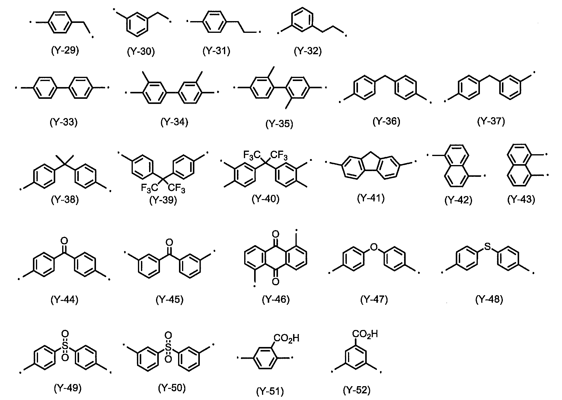

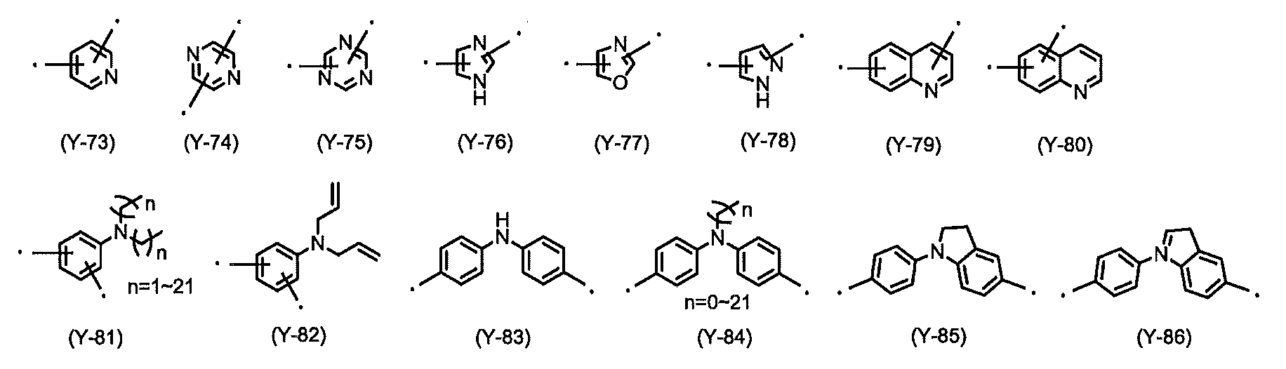


テトラカルボン酸二無水物は下記一般式(TC)で表すことができる。下記式中、Xは4価の有機基であり、その構造は特に限定されない。

具体的なXの例を以下に示すが、これらの構造に限定はしない。


本発明で重要となる偏光紫外線照射によって異方性を発現する液晶配向膜を形成するための組成物(光配向剤)に含有されるポリイミド前駆体、又はポリイミドの種類の例としては、下記構造式(1)~(5)を主鎖構造中に含有するものが挙げられる。
式(1)~(5)中、Z1~Z4はそれぞれ独立して、水素原子、メチル基、及びベンゼン環からなる群から選ばれる少なくとも1種を示し、R1は水素原子、メチル基、エチル基、プロピル基、イソプロピル基、イソブチル基、及びt-ブチル基からなる群より選ばれる有機基を表し、R2は水素原子、フッ素原子、または下記式(式中、R3は水素原子または炭素数1~18のアルキル鎖を表し、mは1~3の整数を表す。黒点は結合部位を表す)に表される有機基を表す。黒点は別の有機基への結合を示す。

本発明においては(5)で表される構造が重要であり、ポリイミド前駆体を含有するワニスや可溶性ポリイミドを含有するワニス(総じて光配向剤)を基板に塗布し、加熱焼成することで(5)に誘導する。この時の焼成温度は200℃から250℃の間で行われることが多く、温度が低すぎるとイミド化に時間がかかり、温度が高すぎると分解反応も併発するため、好ましくは210℃~240℃である。
また、通常の合成手法で、上記で得られた式[D]の重合体に、式[A]で示されるA1及びA2の炭素数1~8のアルキル基、及び式[A]で示されるA3及びA4の炭素数1~5のアルキル基又はアセチル基を導入することもできる。
紫外線を照射した際、分解物が生じるが、この分解物は加熱処理や溶媒による洗浄などで除去することができ、これらの処理を行うことで更にポリマー鎖の再配向なども促すことができるため、液晶の配向品質を更に向上させることができる。加熱処理を行う場合、加熱温度は150℃から250℃の間で行うのが好ましいが、温度が低いと分解物の昇華や蒸発が十分に促進できず、高すぎるとポリマー鎖の分解も併発する可能性があるため、更に好ましくは200℃~230℃である。加熱時間は特に限定はしないが、短すぎると分解物が十分に除去できないため、好ましくは5~30分である。
水と有機溶媒との混合溶媒としては、水と有機溶媒との質量比が、好ましくは20/80~80/20、より好ましくは40/60~60/40である。有機溶媒としては、2-プロパノール、メタノール、エタノール、1-メトキシ-2-プロパノール、乳酸エチル、ジアセトンアルコール、3-メトキシプロピオン酸メチル、又は3-エトキシプロピオン酸エチルが挙げられる。なかでも、2-プロパノール、メタノール、又はエタノールが好ましく、特に、2-プロパノールが好ましい。
上記接触処理の後に、使用した有機溶媒を除去する目的で、水、2-プロパノール、アセトンなどの低沸点溶媒によるすすぎ(リンス)や乾燥のいずれか、又は両方を行ってよい。
液晶配向膜の接触処理としては、浸漬処理、噴霧(スプレー)処理などの、膜と液とが十分に接触する処理が好ましい。接触処理としては、水、又は水と有機溶媒との混合溶媒からなる水性液に膜を、好ましくは10秒~1時間、より好ましくは1分~30分浸漬処理する方法が好ましい。接触処理は常温でも加温してもよいが、好ましくは10~80℃、より好ましくは20~50℃で実施される。また、必要に応じて超音波などの接触を高める手段を施すことができる。
一般式[A]において、R2に以下の(6)~(10)(式中、X1、X2はそれぞれ独立して炭素原子、又は窒素原子を表し、Y1、Y2はそれぞれ独立して水素原子、メチル基、シアノ基、フッ素原子、又は塩素原子を表し、X3は酸素原子、又は硫黄原子を表し、X4は単結合、炭素原子、酸素原子、又は硫黄原子を表し、R4、R5はそれぞれ独立して水素原子、メチル基、メトキシ基、ジメチルアミノ基、フッ素原子、又は塩素原子を表し、pは1~4の整数を表し、qは1~3の整数を表し、破線は別の有機基への結合を示す。)に示す構造を有するポリイミド前駆体やポリイミドも本発明の光配向剤に含めることができる。


必要に応じて純水や溶媒などで洗浄を行っても良い。
使用される高分子が、下記式(6)~(8)又は(11)で表される構造を側鎖の一部として有する高分子を本発明の光配向剤に含めることもできる。式(6)~(8)又は(11)中、X1、X2はそれぞれ独立して炭素原子、又は窒素原子を表し、Y1、Y2はそれぞれ独立して水素原子、メチル基、シアノ基、フッ素原子、又は塩素原子を表し、X3は酸素原子、又は硫黄原子を表し、X4は単結合、炭素原子、酸素原子、又は硫黄原子を表し、R4、R5はそれぞれ独立して水素原子、メチル基、メトキシ基、ジメチルアミノ基、フッ素原子、又は塩素原子を表し、Arは2、5-フラニレン、チオフェン-2,5-ジイル、ピリミジン-2,5-ジイル、ピリジン-2,5-ジイル、フェニレン、1,4-または2,6-ナフチレン、2,5-もしくは2,6-ベンゾフラニレン、又は2,5-もしくは2,6-ベンゾチオフェニレンを表し、これらの芳香環に結合する水素原子の一部はメチル基、メトキシ基、ジメチルアミノ基、フッ素原子、又は塩素原子に置き換わっても良い。pは1~4の整数を表し、黒点は水素原子または別の有機基への結合を示す。


これらの重合体を本発明の光配向剤に含めて使用する場合、成膜後焼成し紫外線を照射したものでも良好な特性が得られるが、ポリマーが液晶性を有する場合、液晶相転移温度近傍で加熱することで更に再配向を促すことができ、液晶配向性を向上させることができる。再配向処理の好ましい温度はポリマーの構造によって異なるため限定は出来ないが、DSC(示差走査熱量分析)やPOM(加熱機構付偏光顕微鏡観察)などであらかじめ液晶相転移温度を調べ、その近傍での温度域を使用するのが好ましい。
下記一般式(式中、破線は別の有機基への結合を示す。)にて表される構造を側鎖の一部として有するポリアクリレート、ポリメタクリレート、ポリN置換マレイミド、ポリスチレン、ポリイタコナート、ポリシロキサンを光配向として用いることもできる。


これらのポリマーを液晶配向膜として使用する場合、成膜後偏光紫外線を照射し、液晶相転移温度近傍で加熱することで更に再配向を促すことができ、液晶配向性を向上させることができる。再配向処理の好ましい温度はポリマーの構造によって異なるため限定は出来ないが、DSC(示差走査熱量分析)やPOM(加熱機構付偏光顕微鏡観察)などであらかじめ液晶相転移温度を調べ、その液晶温度域を使用するのが好ましい。
本発明の光配向剤について、上記で述べた偏光紫外線照射によって異方性を発現する液晶配向膜を形成するための重合体成分のみでも良く、当該特性を損なわない範囲であれば、他の特性の観点で上記以外の重合体成分を混合して用いても良い。
上記以外の重合体として好ましい材料例としてはポリアミック酸、可溶性ポリイミド、ポリアミック酸エステルなどが挙げられる。
例えば、光配向剤中において、非感光性ポリアミック酸、ポリイミドを、偏光紫外線照射によって異方性を発現する重合体100質量部に対して、好ましくは10~1000質量部、より好ましくは10~800質量部含有させることができる。
本発明の光配向剤は、上記の重合体成分以外の成分を含有してもよい。その例としては、光配向剤を塗布した際の膜厚均一性や表面平滑性を向上させる溶媒や化合物、液晶配向膜と基板との密着性を向上させる化合物などである。
例えば、イソプロピルアルコール、メトキシメチルペンタノール、メチルセロソルブ、エチルセロソルブ、ブチルセロソルブ、メチルセロソルブアセテート、エチルセロソルブアセテート、ブチルカルビトール、エチルカルビトール、エチルカルビトールアセテート、エチレングリコール、エチレングリコールモノアセテート、エチレングリコールモノイソプロピルエーテル、エチレングリコールモノブチルエーテル、プロピレングリコール、プロピレングリコールモノブチルエーテル、プロピレングリコールモノアセテート、プロピレングリコールモノメチルエーテル、プロピレングリコール-tert-ブチルエーテル、ジプロピレングリコールモノメチルエーテル、ジエチレングリコール、ジエチレングリコールモノアセテート、ジエチレングリコールジメチルエーテル、ジプロピレングリコールモノアセテートモノメチルエーテル、ジプロピレングリコールモノメチルエーテル、ジプロピレングリコールモノエチルエーテル、ジプロピレングリコールモノアセテートモノエチルエーテル、ジプロピレングリコールモノプロピルエーテル、ジプロピレングリコールモノアセテートモノプロピルエーテル、3-メチル-3-メトキシブチルアセテート、トリプロピレングリコールメチルエーテル、3-メチル-3-メトキシブタノール、ジイソプロピルエーテル、エチルイソブチルエーテル、ジイソブチレン、アミルアセテート、ブチルブチレート、ブチルエーテル、ジイソブチルケトン、メチルシクロへキセン、プロピルエーテル、ジヘキシルエーテル、1-ヘキサノール、n-へキサン、n-ペンタン、n-オクタン、ジエチルエーテル、乳酸メチル、乳酸エチル、酢酸メチル、酢酸エチル、酢酸n-ブチル、酢酸プロピレングリコールモノエチルエーテル、ピルビン酸メチル、ピルビン酸エチル、3-メトキシプロピオン酸メチル、3-エトキシプロピオン酸メチルエチル、3-メトキシプロピオン酸エチル、3-エトキシプロピオン酸、3-メトキシプロピオン酸、3-メトキシプロピオン酸プロピル、3-メトキシプロピオン酸ブチル、1-メトキシ-2-プロパノール、1-エトキシ-2-プロパノール、1-ブトキシ-2-プロパノール、1-フェノキシ-2-プロパノール、プロピレングリコールモノアセテート、プロピレングリコールジアセテート、プロピレングリコール-1-モノメチルエーテル-2-アセテート、プロピレングリコール-1-モノエチルエーテル-2-アセテート、ジプロピレングリコール、2-(2-エトキシプロポキシ)プロパノール、乳酸メチルエステル、乳酸エチルエステル、乳酸n-プロピルエステル、乳酸n-ブチルエステル、乳酸イソアミルエステルなどの低表面張力を有する溶媒などが挙げられる。
これらの貧溶媒は1種類でも複数種類を混合して用いてもよい。上記のような溶媒を用いる場合は、光配向剤に含まれる溶媒全体の5~80質量%であることが好ましく、より好ましくは20~60質量%である。
より具体的には、例えば、エフトップEF301、EF303、EF352(トーケムプロダクツ社製))、メガファックF171、F173、R-30(大日本インキ社製)、フロラードFC430、FC431(住友スリーエム社製)、アサヒガードAG710、サーフロンS-382、SC101、SC102、SC103、SC104、SC105、SC106(旭硝子社製)などが挙げられる。これらの界面活性剤の使用割合は、光配向剤に含有される樹脂成分の100質量部に対して、好ましくは0.01~2質量部、より好ましくは0.01~1質量部である。
例えば、3-アミノプロピルトリメトキシシラン、3-アミノプロピルトリエトキシシラン、2-アミノプロピルトリメトキシシラン、2-アミノプロピルトリエトキシシラン、N-(2-アミノエチル)-3-アミノプロピルトリメトキシシラン、N-(2-アミノエチル)-3-アミノプロピルメチルジメトキシシラン、3-ウレイドプロピルトリメトキシシラン、3-ウレイドプロピルトリエトキシシラン、N-エトキシカルボニル-3-アミノプロピルトリメトキシシラン、N-エトキシカルボニル-3-アミノプロピルトリエトキシシラン、N-トリエトキシシリルプロピルトリエチレントリアミン、N-トリメトキシシリルプロピルトリエチレントリアミン、10-トリメトキシシリル-1,4,7-トリアザデカン、10-トリエトキシシリル-1,4,7-トリアザデカン、9-トリメトキシシリル-3,6-ジアザノニルアセテート、9-トリエトキシシリル-3,6-ジアザノニルアセテート、N-ベンジル-3-アミノプロピルトリメトキシシラン、N-ベンジル-3-アミノプロピルトリエトキシシラン、N-フェニル-3-アミノプロピルトリメトキシシラン、N-フェニル-3-アミノプロピルトリエトキシシラン、N-ビス(オキシエチレン)-3-アミノプロピルトリメトキシシラン、N-ビス(オキシエチレン)-3-アミノプロピルトリエトキシシラン、エチレングリコールジグリシジルエーテル、ポリエチレングリコールジグリシジルエーテル、プロピレングリコールジグリシジルエーテル、トリプロピレングリコールジグリシジルエーテル、ポリプロピレングリコールジグリシジルエーテル、ネオペンチルグリコールジグリシジルエーテル、1,6-ヘキサンジオールジグリシジルエーテル、グリセリンジグリシジルエーテル、2,2-ジブロモネオペンチルグリコールジグリシジルエーテル、1,3,5,6-テトラグリシジル-2,4-ヘキサンジオール、N,N,N’,N’-テトラグリシジル-m-キシレンジアミン、1,3-ビス(N,N-ジグリシジルアミノメチル)シクロヘキサン、N,N,N’,N’-テトラグリシジル-4、4’-ジアミノジフェニルメタンなどが挙げられる。
架橋性添加剤の例としては、フェノプラスト系添加剤、アミノプラスト系添加剤、エポキシ系添加剤、アクリル系添加剤、シランカップリング剤、ブロックイソシアネート系添加剤、オキサゾリン系化合物、β-ヒドロキシアルキルアミド(プリミド)系架橋剤などが挙げられるが、これらに限定されることはない。
フェノプラスト系添加剤の具体例を以下に示すが、これらに限定されるものではない。


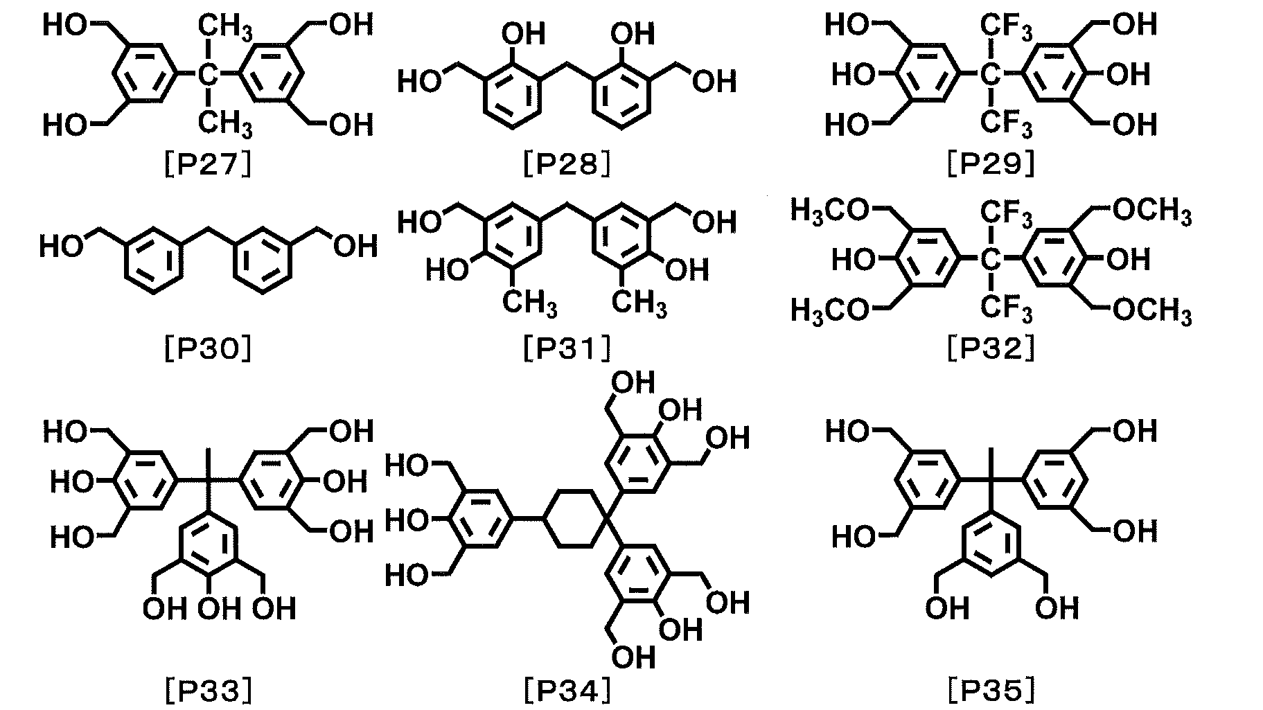


ヒドロキシル基又はアルコキシル基からなる群より選ばれる少なくとも1種の置換基を有する架橋性化合物としては、例えば、ヒドロキシル基又はアルコキシル基を有するアミノ樹脂、例えばメラミン樹脂、尿素樹脂、グアナミン樹脂、グリコールウリル-ホルムアルデヒド樹脂、スクシニルアミド-ホルムアルデヒド樹脂、エチレン尿素-ホルムアルデヒド樹脂などが挙げられる。
この架橋性化合物は、例えば、アミノ基の水素原子がメチロール基又はアルコキシメチル基又はその両方で置換されたメラミン誘導体、ベンゾグアナミン誘導体又はグリコールウリルを用いることができる。このメラミン誘導体及びベンゾグアナミン誘導体は二量体又は三量体として存在することも可能である。これらはトリアジン環1個当たり、メチロール基又はアルコキシメチル基を平均3個以上6個以下有するものが好ましい。
このようなメラミン誘導体又はベンゾグアナミン誘導体の例としては、市販品のトリアジン環1個当たりメトキシメチル基が平均3.7個置換されているMX-750、トリアジン環1個当たりメトキシメチル基が平均5.8個置換されているMW-30(以上、三和ケミカル製)や、サイメル300、301、303、350、370、771、325、327、703、712などのメトキシメチル化メラミン、サイメル235、236、238、212、253、254などのメトキシメチル化ブトキシメチル化メラミン、サイメル506、508などのブトキシメチル化メラミン、サイメル1141のようなカルボキシル基含有メトキシメチル化イソブトキシメチル化メラミン、サイメル1123のようなメトキシメチル化エトキシメチル化ベンゾグアナミン、サイメル1123-10のようなメトキシメチル化ブトキシメチル化ベンゾグアナミン、サイメル1128のようなブトキシメチル化ベンゾグアナミン、サイメル1125-80のようなカルボキシル基含有メトキシメチル化エトキシメチル化ベンゾグアナミン(以上、三井サイアナミド製)が挙げられる。また、グリコールウリルの例として、サイメル1170のようなブトキシメチル化グリコールウリル、サイメル1172のようなメチロール化グリコールウリル等、パウダーリンク1174のようなメトキシメチロール化グリコールウリル等が挙げられる。
エポキシ基又はイソシアネート基を有する架橋性化合物としては、例えばビスフェノールアセトングリシジルエーテル、フェノールノボラックエポキシ樹脂、クレゾールノボラックエポキシ樹脂、トリグリシジルイソシアヌレート、テトラグリシジルアミノジフェニレン、テトラグリシジル-m-キシレンジアミン、テトラグリシジル-1,3-ビス(アミノエチル)シクロヘキサン、テトラフェニルグリシジルエーテルエタン、トリフェニルグリシジルエーテルエタン、ビスフェノールヘキサフルオロアセトジグリシジルエーテル、1,3-ビス(1-(2,3-エポキシプロポキシ)-1-トリフルオロメチル-2,2,2-トリフルオロメチル)ベンゼン、4,4-ビス(2,3-エポキシプロポキシ)オクタフルオロビフェニル、トリグリシジル-p-アミノフェノール、テトラグリシジルメタキシレンジアミン、2-(4-(2,3-エポキシプロポキシ)フェニル)-2-(4-(1,1-ビス(4-(2,3-エポキシプロポキシ)フェニル)エチル)フェニル)プロパン、1,3-ビス(4-(1-(4-(2,3-エポキシプロポキシ)フェニル)-1-(4-(1-(4-(2,3-エポキシプロポキシフェニル)-1-メチルエチル)フェニル)エチル)フェノキシ)-2-プロパノール等が挙げられる。エポキシ基を2つ以上含有する化合物としては、具体的には、以下のような化合物が例示される。


オキセタン基を有する架橋性化合物としては、下記の式[4]で示すオキセタン基を少なくとも2個有する架橋性化合物である。


ブロックイソシアネート基を2つ以上含有する化合物としては、下記式(5)で表されるブロックイソシアネート基を有する化合物が例示される。 Zはそれぞれ独立して、炭素数1~3のアルキル基、水酸基又は下記式(6)で表される有機基であり、Zの少なくとも1つは、下記式(6)で表される有機基である。


オキサゾリン化合物としては、2,2’-ビス(2-オキサゾリン)、1,2,4-トリス-(2-オキサゾリニル-2)-ベンゼン、4-フラン-2-イルメチレン-2-フェニル-4H-オキサゾール-5-オン、1,4-ビス(4,5-ジヒドロ-2-オキサゾリル)ベンゼン、1,3-ビス(4,5-ジヒドロ-2-オキサゾリル)ベンゼン、2,3-ビス(4-イソプロペニル-2-オキサゾリン-2-イル)ブタン、2,2’-ビス-4-ベンジル-2-オキサゾリン、2,6-ビス(イソプロピル-2-オキサゾリン-2-イル)ピリジン、2,2’-イソプロピリデンビス(4-tert-ブチル-2-オキサゾリン)、2,2’-イソプロピリデンビス(4-フェニル-2-オキサゾリン)、2,2’-メチレンビス(4-tert-ブチル-2-オキサゾリン)、及び2,2’-メチレンビス(4-フェニル-2-オキサゾリン)が挙げられる。これらの他、エポクロス(商品名、株式会社日本触媒製)のようなオキサゾリルを有するポリマーやオリゴマーも挙げることができる。
プリミド系架橋剤とは、ヒドロキシアルキルアミド基を有する化合物である。(B)成分は、ヒドロキシアルキルアミド基を有していれば、その他の構造は特に限定されないが、入手性等の点から、好ましい例として、下記式(2)で表される化合物が挙げられる。式中、X2は炭素数1~20の脂肪族炭化水素基、又は芳香族炭化水素基を含むn価の有機基である。nは2~6の整数である。R2及びR3は、それぞれ独立して、水素原子、置換基を有してもよい炭素数1~4のアルキル基、置換基を有してもよい炭素数2~4のアルケニル基、又は置換基を有してもよい炭素数2~4のアルキニル基である。また、R2及びR3のうち少なくとも1つは、ヒドロキシ基で置換された炭化水素基を表す。

式(2)中、nは、溶解性の観点から、2~4が好ましい。


好ましい添加量は0.1重量%~30重量%であり、好ましくは0.5重量%~10重量%である。
重合性不飽和結合を有する架橋性化合物としては、トリメチロールプロパントリ(メタ)アクリレート、ペンタエリスリトールトリ(メタ)アクリレート、ジペンタエリスリトールペンタ(メタ)アクリレート、トリ(メタ)アクリロイルオキシエトキシトリメチロールプロパン、グリセリンポリグリシジルエーテルポリ(メタ)アクリレート等の重合性不飽和基を分子内に3個有する架橋性化合物、さらに、エチレングリコールジ(メタ)アクリレート、ジエチレングリコールジ(メタ)アクリレート、テトラエチレングリコールジ(メタ)アクリレート、ポリエチレングリコールジ(メタ)アクリレート、プロピレングリコールジ(メタ)アクリレート、ポリプロピレングリコールジ(メタ)アクリレート、ブチレングリコールジ(メタ)アクリレート、ネオペンチルグリコールジ(メタ)アクリレート、エチレンオキサイドビスフェノールA型ジ(メタ)アクリレート、プロピレンオキサイドビスフェノール型ジ(メタ)アクリレート、1,6-へキサンジオールジ(メタ)アクリレート、グリセリンジ(メタ)アクリレート、ペンタエリスリトールジ(メタ)アクリレート、エチレングリコールジグリシジルエーテルジ(メタ)アクリレート、ジエチレングリコールジグリシジルエーテルジ(メタ)アクリレート、フタル酸ジグリシジルエステルジ(メタ)アクリレート、ヒドロキシピバリン酸ネオペンチルグリコールジ(メタ)アクリレート等の重合性不飽和基を分子内に2個有する架橋性化合物、加えて、2-ヒドロキシエチル(メタ)アクリレート、2-ヒドロキシプロピル(メタ)アクリレート、2-ヒドロキシブチル(メタ)アクリレート、2-フェノキシ-2-ヒドロキシプロピル(メタ)アクリレート、2-(メタ)アクリロイルオキシ-2-ヒドロキシプロピルフタレート、3-クロロ-2-ヒドロキシプロピル(メタ)アクリレート、グリセリンモノ(メタ)アクリレート、2-(メタ)アクリロイルオキシエチルリン酸エステル、N-メチロール(メタ)アクリルアミド等の重合性不飽和基を分子内に1個有する架橋性化合物が挙げられる。
加えて、下記の式[5]で示される化合物を用いることもできる。

チイラン化合物としては、フェニルグリシジルエーテル、ブチルグリシジルエーテル、3,3,3-トリフルオロメチルプロピレンオキシド、スチレンオキシド、ヘキサフルオロプロピレンオキシド、シクロヘキセンオキシド、N-グリシジルフタルイミド、(ノナフルオロ-N-ブチル)エポキシド、パーフルオロエチルグリシジルエーテル、エピクロロヒドリン、エピブロモヒドリン、N,N-ジグリシジルアニリン、及び3-[2-(パーフルオロヘキシル)エトキシ]-1,2-エポキシプロパン、エチレングリコールジグリシジルエーテル、ポリエチレングリコールジグリシジルエーテル、プロピレングリコールジグリシジルエーテル、トリプロピレングリコールジグリシジルエーテル、ポリプロピレングリコールジグリシジルエーテル、ネオペンチルグリコールジグリシジルエーテル、1,6-ヘキサンジオールジグリシジルエーテル、グリセリンジグリシジルエーテル、2,2-ジブロモネオペンチルグリコールジグリシジルエーテル、及び3-(N,N-ジグリシジル)アミノプロピルトリメトキシシラン、1,3,5,6-テトラグリシジル-2,4-ヘキサンジオール、N,N,N’,N’-テトラグリシジル-m-キシレンジアミン、1,3-ビス(N,N-ジグリシジルアミノメチル)シクロヘキサン、N,N,N’,N’,-テトラグリシジル-4,4’-ジアミノジフェニルメタン、及び3-(N-アリル-N-グリシジル)アミノプロピルトリメトキシシランにおけるグリシジル基の酸素を、例えばJ.Org.Chem.,28,229(1963)に記載されている方法に従って硫黄に置換し、前記グリシジル基をエチレンスルフィド基に変換したもの、が挙げられる。
アジリジン化合物としては、2,4,6-トリス(1’-アジリジニル)-1,3,5-トリアジン、ω-アジリジニルプロピオン酸-2,2-ジヒドロキシメチル-ブタノールトリエステル、2,4,6-トリス(2-メチル-1-アジリジニル)-1,3,5-トリアジン、2,4,6-トリス(2-エチル-1-アジリジニル)-1,3,5-トリアジン、4,4’-ビス(エチレンイミノカルボニルアミノ)ジフェニルメタン、ビス(2-エチル-1-アジリジニル)ベンゼン-1,3-ジカルボン酸アミド、トリス(2-エチル-1-アジリジニル)ベンゼン-1,3,5-トリカルボン酸アミド、ビス(2-エチル-1-アジリジニル)セバシン酸アミド、1,6-ビス(エチレンイミノカルボニルアミノ)ヘキサン、2,4-ジエチレンウレイドトルエン、1,1’-カルボニル-ビス-エチレンイミン、ポリメチレン-ビス-エチレンユリア(C2~C4)、及びN,N’-ビス(4,6-ジエチレンイミノ-1,3,5-トリアジン-2-イル)-ヘキサメチレンジアミンが挙げられる。これらの他、アジリジニルを有するオリゴマーやポリマーも挙げることができる。


本発明の光配向剤において、各重合体を溶解するのに使用される有機溶媒としては、本発明の光配向剤に用いる有機溶媒(溶剤)は、重合体成分を溶解させる有機溶媒であれば特に限定されない。その具体例を以下に挙げる。
N,N-ジメチルホルムアミド、N,N-ジメチルアセトアミド、N-メチル-2-ピロリドン、N-メチルカプロラクタム、2-ピロリドン、N-エチルピロリドン、N-ビニルピロリドン、ジメチルスルホキシド、テトラメチル尿素、ピリジン、ジメチルスルホン、γ-ブチロラクトン、3-メトキシ-N,N-ジメチルプロパンアミド、3-エトキシ-N,N-ジメチルプロパンアミド、3-ブトキシ-N,N-ジメチルプロパンアミド、1,3-ジメチル-イミダゾリジノン、エチルアミルケトン、メチルノニルケトン、メチルエチルケトン、メチルイソアミルケトン、メチルイソプロピルケトン、シクロヘキサノン、エチレンカーボネート、プロピレンカーボネート、ジグライム、4-ヒドロキシ-4-メチル-2-ペンタノンなどが挙げられる。これらは単独で使用しても、混合して使用してもよい。
上述の光配向剤は、本発明の液晶配向膜、具体的には液晶フレネルレンズに用いられる液晶配向膜を形成するために好適に使用することができる。
本発明の光配向剤を用いて液晶配向膜を形成するには、基板上に、光配向剤を塗布して塗膜を形成し、該塗膜に上述の式により設計した偏光方位のパターンに沿って放射線を照射する工程を経る方法によることができる。
本発明の液晶フレネルレンズに用いられる液晶は、従来、液晶表示素子などに用いられているネマチック液晶や強誘電性液晶などをそのまま用いることができる。
具体的には、4-シアノ-4’-n-ペンチルビフェニル、4-シアノ-4’-n-へプチルオキシビフェニル等のシアノビフェニル類;コレステリルアセテート、コレステリルベンゾエート等のコレステリルエステル類;4-カ ルボキシフェニルエチルカーボネート、4-カルボキシフェニル-n-ブチルカーボネート等の炭酸エステル類;安息香酸フェニルエステル、フタル酸ビフェニ ルエステル等のフェニルエステル類;ベンジリデン-2-ナフチルアミン、4’-n-ブトキシベンジリデン-4-アセチルアニリン等のシッフ塩基類;N,N’-ビスベンジリデンベンジジン、p-ジアニスアルベンジジン等のベンジジン類;4,4’-アゾキシジアニソール、4,4’-ジ-n-ブトキシ アゾキシベンゼン等のアゾキシベンゼン類;以下に具体的に示すフェニルシクロヘキシル系、ターフェニル系、フェニルビシクロヘキシル系などの液晶;などを挙げることができるがこれらに限定されない。


(メタクリルモノマー)
下記のMA1を用いた。該MA1は、非特許文献(Macromolecules 2002, 35, 706-713)に記載の合成法にて合成した。

THF:テトラヒドロフラン
CH2Cl2:ジクロロメタン
(重合開始剤)
AIBN:2,2’-アゾビスイソブチロニトリル
[相転移温度の測定]
実施例により得られたポリマーの液晶相転移温度は示差走査熱量測定(DSC)DSC3100SR(マック・サイエンス社製)を用いて測定した。
MA1(10.29g、20.0mmol)をTHF(94.1g)中に溶解し、ダイアフラムポンプで脱気を行った後、AIBN(0.164g、1.0mmol)を加え再び脱気を行った。この後50℃で30時間反応させメタクリレートのポリマー溶液を得た。このポリマー溶液をメタノール(1000ml)に滴下し、得られた沈殿物をろ過した。この沈澱物をメタノールで洗浄し、40℃のオーブン中で減圧乾燥しメタクリレートポリマー粉末(A)を得た。このポリマーの数平均分子量は19000、重量平均分子量は39000であった。
得られたメタクリレートポリマー粉末(A)(1.5g)にCH2Cl2(98.5g)を加え、室温で5時間攪拌して溶解させ液晶配向剤(A1)を得た。
使用する光の基準波長633 nm,焦点距離200 mmとしてフレネルレンズを設計した。この時、フレネルレンズは切替部の位相差が2πのとき最も集光度が高くなる。位相をδ、中心からの距離をrとしたとき、フレネルレンズの位相分布は図5のようになる。

上記で得られた液晶配向剤(A1)を、準備されたガラス基板にスピンコートした。次いで、70℃のホットプレートで90秒間乾燥し、膜厚100nmの液晶配向膜を形成した。
次いで、製膜したガラス基板の製膜面が向かい合うように張り合わせ、空セルを作製した。
作製した空セルに対して直径20μmに集光した波長325nmの直線偏光紫外光(LPUV)を下記図7の装置を用いて、任意のパターンに沿って1800mJ/cm2照射した。
図8の顕微鏡写真の通り、フレネルパターンに沿って異方性空間分布が形成されていることが分かる。
測定はλ=633nmのHe-Neレーザを用いて右回り円偏光(RCP)、左回り円偏光(LCP)、直線偏光(LP)を入射することで実施した。その際、温度コントローラーで液晶フレネルレンズの温度をコントロールすることにより、液晶の屈折率を調整した。ビームプロファイラで出射光の強度分布を取得した。取得したプロファイラ画像を図9に示す。
Incident beam(図9左端)は、規格化した際に強度が非常に弱いため、100倍にしたグラフを破線で示す。
即ち、右回り円偏光(図9中、「RCP」と記載)を入射した場合(図9の右から2番目、特に下段)には入射光に比べて強度が中心部に集中しており集光していることがわかる。
直線偏光(図9中、「LP」と記載)を入射した場合(図9の左から2番目、特に下段)にも集光していることがわかる。しかし、LPを入射した場合においては、RCPを入射した場合に比べて強度が約半分になっており、LPの右回り成分のみが集光していることがわかる。
また、左回り円偏光(図9中、「LCP」と記載)を入射した場合(図9の右端、特に下段)、図9の右端の下段の図において、強度が観察されないこと、即ち集光が見られないことがわかる。これは、LCPを入射した場合に、LCPの拡散が生じているためと考えられる。
これらの結果から、本実施例で得られた液晶フレネルレンズは、入射光の偏光状態により異なる特性が得られることがわかる。なお、この特性は、設計条件とよく一致している。
図10から次のことがわかる。即ち、集光が確認されているRCPとLPともに楕円率が-1(白)となっているため、LCPに変換されて集光していることがわかる。なお、図10の白黒図面では不明瞭ではあるが、図10中の「白」となっている箇所は、LCPに変換されて集光していることを示し、図10中の「白」以外の箇所は、光強度がゼロ又は非常に弱いことを示す。
図9の結果と図10の結果を合わせて考慮すると、本実施例で得られた液晶フレネルレンズは、右回り成分を左回りに変換し集光していることがわかる。
Claims (20)
- 配向分子を備えた液晶配向膜であって、前記配向分子は、前記液晶配向膜の所定の点から所定距離の位置にあるとき、前記配向分子の配向方向が、前記液晶配向膜が形成する平面と平行な直線に対して、前記距離に応じた角度をなす、液晶配向膜。
- 前記所定距離r1の位置にある前記配向方向の角度がθ1であり、前記所定距離r1に最近接する距離r2の位置にある配向分子の配向方向の角度がθ2であり、角度θ1とθ2との差Δθが0°を越えて90°未満である請求項1記載の液晶配向膜。
- 前記距離に応じた前記角度が、フレネルレンズ形状に近似する角度分布を有する請求項1又は請求項2記載の液晶配向膜。
- 前記配向分子が、光架橋、光異性化、光フリース転移、及び光分解からなる群から選ばれる少なくとも1種の光反応を生じる基を有する高分子である請求項1~3のいずれか1項記載の液晶配向膜。
- 前記配向分子が、光架橋、光異性化、光フリース転移、及び光分解からなる群から選ばれる少なくとも1種の光反応を生じる側鎖を有する高分子である請求項1~4のいずれか1項記載の液晶配向膜。
- 請求項1~5のいずれか1項記載の液晶配向膜を片面に有する基板。
- 請求項6記載の基板である第1の基板;及び
第2の基板;を有し、
前記第1及び第2の基板を、空間を備えて平行離間させ、且つ前記第1の基板の液晶配向膜を第2の基板に対向するように配置し、且つ
前記第1及び第2の基板を、前記第1の基板の法線であって前記第1の基板の所定の点である第1の点を通る第1の法線が前記第2の基板の法線となるように、配置する、
液晶セル。 - 前記第2の基板が、請求項6記載の基板であり、
前記第1及び第2の基板を、前記第1の基板の法線であって前記第1の基板の中心点である第1の中心点を通る第1の法線と、前記第2の基板の法線であって前記第2の基板の中心点である第2の中心点を通る第21の法線と一致するように、配置する、請求項7記載の液晶セル。 - 前記空間に液晶を備える、請求項7又は請求項8記載の液晶セル。
- 請求項9記載の液晶セルを備える液晶光学素子。
- 液晶配向膜の製造方法であって、
A)光架橋、光異性化、光フリース転移、及び光分解からなる群から選ばれる少なくとも1種の光反応を生じる基を有する高分子を有する膜を形成する工程;及び
B)前記膜の所定位置に所定の偏光紫外線を照射する工程;
を有し、
前記膜の所定の点から所定の距離の位置にある高分子の配向方向を、前記膜が形成する平面と平行な直線に対して、前記距離に応じた角度をなす配向分子を備える液晶配向膜を得る、上記方法。 - 前記A)において、前記基が前記高分子の側鎖に有する、請求項11記載の方法。
- 前記B)において、前記所定の偏光紫外線が集光した偏光紫外線である請求項11又は請求項12記載の方法。
- 前記A)において、A)-1)前記膜を基板上に形成する請求項11~13のいずれか1項記載の方法。
- D) 請求項14記載の方法により得られた基板である第1の基板を準備する工程;
E) 第2の基板を準備する工程;及び
F) 前記第1の基板及び第2の基板との間に液晶を備える工程;
を有し、
前記F)において、前記第1及び第2の基板を、前記第1の基板の液晶配向膜を第2の基板に対向するように、平行離間させて配置し、且つ前記第1及び第2の基板を、前記第1の基板の法線であって前記第1の基板の中心点である第1の中心点を通る第1の法線が前記第2の基板の法線となるように配置する、
液晶セル又は液晶光学素子の製造方法。 - 前記第2の基板が、請求項14記載の方法により得られた基板であり、
前記F)において、前記第1及び第2の基板を、前記第1の基板の法線であって前記第1の基板の中心点である第1の中心点を通る第1の法線が前記第2の基板の法線であって前記第2の基板の中心点である第2の中心点を通る第2の法線と一致するように配置する、請求項15記載の方法。 - 液晶セルの製造方法であって、
O)第1及び第2の基板を準備する工程;
P1)第1の基板の片面上に第1の膜を形成する工程であって、該第1の膜が、光架橋、光異性化、光フリース転移、及び光分解からなる群から選ばれる少なくとも1種の光反応を生じる第1の基を有する第1の高分子を有する工程;
P2)第2の基板の片面上に前記第1の膜と同じであっても異なってもよい第2の膜を形成する工程であって、該第2の膜が、光架橋、光異性化、光フリース転移、及び光分解からなる群から選ばれる少なくとも1種の光反応を生じる第2の基を有する第2の高分子を有する工程;
Q)前記第1の膜を備える第1の基板及び前記第2の膜を備える第2の基板を、第1の膜及び第2の膜が対向するように、空間を備えるように平行離間して配置する工程;及び
R)前記第1の膜を有しない前記第1の基板の面側から、又は、前記第2の膜を有しない前記第2の基板の面側から、前記第1の膜及び前記第2の膜の所定位置に所定の偏光紫外線を照射する工程;
を有し、
前記第1の膜の所定の第1の点から所定距離の位置にある第1の高分子の配向方向を、前記第1の膜が形成する第1の平面と平行な第1の直線に対して、前記距離に応じた角度をなす第1の配向分子を備える第1の液晶配向膜を有し、且つ
前記第2の膜の所定の第2の点から所定距離の位置にある第2の高分子の配向方向を、前記第2の膜が形成する第2の平面と平行な第2の直線に対して、前記距離に応じた角度をなす第2の配向分子を備える第2の液晶配向膜を有する、液晶セルを得る、上記方法。 - 前記第1の基が前記第1の高分子の側鎖に有するか、及び/又は前記第2の基が前記第2の高分子の側鎖に有する請求項17記載の方法。
- 前記R)において、前記所定の偏光紫外線が集光した偏光紫外線である請求項17又は請求項18記載の方法。
- 前記工程R)後、T)液晶を前記空間に充填する工程;をさらに有する請求項17~19のいずれか1項記載の方法又は液晶光学素子の製造方法。
Priority Applications (3)
| Application Number | Priority Date | Filing Date | Title |
|---|---|---|---|
| CN201780051423.8A CN109643036B (zh) | 2016-06-22 | 2017-06-21 | 液晶光学元件和液晶光学元件的制造方法 |
| JP2018524128A JP7131771B2 (ja) | 2016-06-22 | 2017-06-21 | 液晶光学素子及び液晶光学素子の製造方法 |
| KR1020197001719A KR102478693B1 (ko) | 2016-06-22 | 2017-06-21 | 액정 광학 소자 및 액정 광학 소자의 제조 방법 |
Applications Claiming Priority (2)
| Application Number | Priority Date | Filing Date | Title |
|---|---|---|---|
| JP2016123217 | 2016-06-22 | ||
| JP2016-123217 | 2016-06-22 |
Publications (1)
| Publication Number | Publication Date |
|---|---|
| WO2017221959A1 true WO2017221959A1 (ja) | 2017-12-28 |
Family
ID=60784308
Family Applications (1)
| Application Number | Title | Priority Date | Filing Date |
|---|---|---|---|
| PCT/JP2017/022793 WO2017221959A1 (ja) | 2016-06-22 | 2017-06-21 | 液晶光学素子及び液晶光学素子の製造方法 |
Country Status (5)
| Country | Link |
|---|---|
| JP (1) | JP7131771B2 (ja) |
| KR (1) | KR102478693B1 (ja) |
| CN (1) | CN109643036B (ja) |
| TW (1) | TWI814704B (ja) |
| WO (1) | WO2017221959A1 (ja) |
Cited By (1)
| Publication number | Priority date | Publication date | Assignee | Title |
|---|---|---|---|---|
| CN107229161A (zh) * | 2017-07-28 | 2017-10-03 | 广西天山电子股份有限公司 | 一种偏振相关的平面液晶透镜及其制备方法 |
Families Citing this family (1)
| Publication number | Priority date | Publication date | Assignee | Title |
|---|---|---|---|---|
| CN111580310B (zh) * | 2020-06-18 | 2023-08-29 | 京东方科技集团股份有限公司 | 液晶透镜、其制作方法及显示装置 |
Citations (4)
| Publication number | Priority date | Publication date | Assignee | Title |
|---|---|---|---|---|
| JPH09197363A (ja) * | 1996-01-23 | 1997-07-31 | Asahi Glass Co Ltd | 光変調素子及び光ヘッド装置 |
| JP2000122062A (ja) * | 1998-10-13 | 2000-04-28 | Sony Corp | 光学素子とその製造方法、及び光学装置とその製造方法 |
| JP2002357804A (ja) * | 2001-06-01 | 2002-12-13 | Nippon Hoso Kyokai <Nhk> | 回折型液晶レンズ及び多焦点回折型液晶レンズ |
| JP2016108417A (ja) * | 2014-12-04 | 2016-06-20 | 日産化学工業株式会社 | 液晶配向剤、液晶配向膜及び液晶表示素子 |
Family Cites Families (6)
| Publication number | Priority date | Publication date | Assignee | Title |
|---|---|---|---|---|
| KR19980051988A (ko) * | 1996-12-24 | 1998-09-25 | 손욱 | 액정 표시 장치의 제조 방법 |
| JP5383601B2 (ja) | 2009-07-06 | 2014-01-08 | シチズンホールディングス株式会社 | 液晶レンズ |
| KR101615926B1 (ko) | 2009-07-28 | 2016-04-28 | 삼성디스플레이 주식회사 | 액정표시장치 및 이의 제조방법 |
| US9551902B2 (en) * | 2010-03-16 | 2017-01-24 | Industry-University Cooperation Foundation Hanyang University | Liquid crystal display with an alignment control layer containing polymerized mesogen and a manufacturing method of the liquid crystal display |
| KR101461047B1 (ko) * | 2010-08-09 | 2014-11-13 | 제이에스알 가부시끼가이샤 | 광지향성 제어 유닛 및 그의 제조 방법, 2d/3d 변환 가능 표시 모듈, 그리고 액정 배향제 |
| JP5893190B2 (ja) | 2015-04-08 | 2016-03-23 | 株式会社東芝 | フレネルレンズ型の液晶レンズ装置及び画像表示装置及び駆動装置 |
-
2017
- 2017-06-21 WO PCT/JP2017/022793 patent/WO2017221959A1/ja active Application Filing
- 2017-06-21 JP JP2018524128A patent/JP7131771B2/ja active Active
- 2017-06-21 TW TW106120779A patent/TWI814704B/zh active
- 2017-06-21 CN CN201780051423.8A patent/CN109643036B/zh active Active
- 2017-06-21 KR KR1020197001719A patent/KR102478693B1/ko active IP Right Grant
Patent Citations (4)
| Publication number | Priority date | Publication date | Assignee | Title |
|---|---|---|---|---|
| JPH09197363A (ja) * | 1996-01-23 | 1997-07-31 | Asahi Glass Co Ltd | 光変調素子及び光ヘッド装置 |
| JP2000122062A (ja) * | 1998-10-13 | 2000-04-28 | Sony Corp | 光学素子とその製造方法、及び光学装置とその製造方法 |
| JP2002357804A (ja) * | 2001-06-01 | 2002-12-13 | Nippon Hoso Kyokai <Nhk> | 回折型液晶レンズ及び多焦点回折型液晶レンズ |
| JP2016108417A (ja) * | 2014-12-04 | 2016-06-20 | 日産化学工業株式会社 | 液晶配向剤、液晶配向膜及び液晶表示素子 |
Cited By (1)
| Publication number | Priority date | Publication date | Assignee | Title |
|---|---|---|---|---|
| CN107229161A (zh) * | 2017-07-28 | 2017-10-03 | 广西天山电子股份有限公司 | 一种偏振相关的平面液晶透镜及其制备方法 |
Also Published As
| Publication number | Publication date |
|---|---|
| CN109643036B (zh) | 2022-09-23 |
| CN109643036A (zh) | 2019-04-16 |
| TW201815914A (zh) | 2018-05-01 |
| KR102478693B1 (ko) | 2022-12-16 |
| JPWO2017221959A1 (ja) | 2019-04-11 |
| TWI814704B (zh) | 2023-09-11 |
| JP7131771B2 (ja) | 2022-09-06 |
| KR20190020762A (ko) | 2019-03-04 |
Similar Documents
| Publication | Publication Date | Title |
|---|---|---|
| JP6504377B2 (ja) | 重合体 | |
| KR101951501B1 (ko) | 액정 배향 처리제, 액정 배향막 및 액정 표시 소자 | |
| JP6497520B2 (ja) | 液晶配向処理剤、液晶配向膜および液晶表示素子 | |
| JP6299977B2 (ja) | 液晶配向処理剤、液晶配向膜および液晶表示素子 | |
| KR20160052632A (ko) | 액정 배향 처리제, 액정 배향막 및 액정 표시 소자 | |
| KR20160104103A (ko) | 조성물, 액정 배향 처리제, 액정 배향막 및 액정 표시 소자 | |
| KR20150087401A (ko) | 액정 배향 처리제, 액정 배향막 및 액정 표시 소자 | |
| KR20140045556A (ko) | 조성물, 액정 배향 처리제, 액정 배향막 및 액정 표시 소자 | |
| WO2017221959A1 (ja) | 液晶光学素子及び液晶光学素子の製造方法 | |
| KR20140009447A (ko) | 조성물, 액정 배향 처리제, 액정 배향막, 및 액정 표시 소자 | |
| WO2017110977A1 (ja) | 液晶表示素子、液晶光学素子及び液晶構造体安定化膜用組成物 | |
| KR101842740B1 (ko) | 조성물, 액정 배향 처리제, 액정 배향막, 및 액정 표시 소자 | |
| WO2018122936A1 (ja) | 液晶配向剤、液晶配向膜、及び液晶表示素子 | |
| JP6981254B2 (ja) | 液晶表示素子、液晶光学素子及び液晶構造体安定化膜用組成物 | |
| WO2016076412A1 (ja) | 液晶配向処理剤、液晶配向膜及び液晶表示素子 |
Legal Events
| Date | Code | Title | Description |
|---|---|---|---|
| 121 | Ep: the epo has been informed by wipo that ep was designated in this application |
Ref document number: 17815427 Country of ref document: EP Kind code of ref document: A1 |
|
| ENP | Entry into the national phase |
Ref document number: 2018524128 Country of ref document: JP Kind code of ref document: A |
|
| NENP | Non-entry into the national phase |
Ref country code: DE |
|
| ENP | Entry into the national phase |
Ref document number: 20197001719 Country of ref document: KR Kind code of ref document: A |
|
| 122 | Ep: pct application non-entry in european phase |
Ref document number: 17815427 Country of ref document: EP Kind code of ref document: A1 |