WO2017221785A1 - ショーケース - Google Patents
ショーケース Download PDFInfo
- Publication number
- WO2017221785A1 WO2017221785A1 PCT/JP2017/021971 JP2017021971W WO2017221785A1 WO 2017221785 A1 WO2017221785 A1 WO 2017221785A1 JP 2017021971 W JP2017021971 W JP 2017021971W WO 2017221785 A1 WO2017221785 A1 WO 2017221785A1
- Authority
- WO
- WIPO (PCT)
- Prior art keywords
- side plate
- abutting
- rectifying member
- showcase
- rectifying
- Prior art date
- Legal status (The legal status is an assumption and is not a legal conclusion. Google has not performed a legal analysis and makes no representation as to the accuracy of the status listed.)
- Ceased
Links
Images


Classifications
-
- A—HUMAN NECESSITIES
- A47—FURNITURE; DOMESTIC ARTICLES OR APPLIANCES; COFFEE MILLS; SPICE MILLS; SUCTION CLEANERS IN GENERAL
- A47F—SPECIAL FURNITURE, FITTINGS, OR ACCESSORIES FOR SHOPS, STOREHOUSES, BARS, RESTAURANTS OR THE LIKE; PAYING COUNTERS
- A47F3/00—Show cases or show cabinets
- A47F3/04—Show cases or show cabinets air-conditioned, refrigerated
-
- F—MECHANICAL ENGINEERING; LIGHTING; HEATING; WEAPONS; BLASTING
- F25—REFRIGERATION OR COOLING; COMBINED HEATING AND REFRIGERATION SYSTEMS; HEAT PUMP SYSTEMS; MANUFACTURE OR STORAGE OF ICE; LIQUEFACTION SOLIDIFICATION OF GASES
- F25D—REFRIGERATORS; COLD ROOMS; ICE-BOXES; COOLING OR FREEZING APPARATUS NOT OTHERWISE PROVIDED FOR
- F25D17/00—Arrangements for circulating cooling fluids; Arrangements for circulating gas, e.g. air, within refrigerated spaces
- F25D17/04—Arrangements for circulating cooling fluids; Arrangements for circulating gas, e.g. air, within refrigerated spaces for circulating air, e.g. by convection
- F25D17/06—Arrangements for circulating cooling fluids; Arrangements for circulating gas, e.g. air, within refrigerated spaces for circulating air, e.g. by convection by forced circulation
- F25D17/08—Arrangements for circulating cooling fluids; Arrangements for circulating gas, e.g. air, within refrigerated spaces for circulating air, e.g. by convection by forced circulation using ducts
Definitions
- the embodiment of the present invention relates to a showcase.
- an air curtain device In order to prevent the cooled air in the showcase from flowing outside, an air curtain device is used.
- a honeycomb-shaped rectifying member is used to rectify air. Since dust accumulates in the rectifying member when air flows, it is necessary to periodically remove the rectifying member from the showcase and clean the rectifying member.
- a first abutting member and a second abutting member that sandwich the rectifying member from the front-rear direction, and a spring that urges the second abutting member disposed rearward forward And a detaching device.
- the detaching device holds the rectifying member by sandwiching both contact members in the front-rear direction by the biasing force of the spring.
- the second contact member is moved rearward against the biasing force of the spring, the second contact member is separated from the rectifying member, and the rectifying member can be removed from the showcase.
- the second contact member may move backward without the user's intention, and the rectifying member may be detached from the showcase.
- the problem to be solved by the present invention is to provide a showcase in which the straightening member is prevented from unintentionally coming off.
- the showcase according to the embodiment includes a first contact member, a second contact member, and a separation regulating portion.
- the first abutting member comes into contact with a rectifying member that rectifies air flowing in the showcase at a first end of the rectifying member.
- the second contact member is disposed at the second end of the rectifying member and is movable away from the rectifying member.
- the separation regulating portion regulates movement of the second abutting member, which is in contact with the rectifying member so as to sandwich the rectifying member together with the first abutting member, to move away from the rectifying member. And a second state in which the second contact member is allowed to move away from the rectifying member.
- the showcase 1 of the present embodiment is a vertical showcase that is installed and used in a store S such as a supermarket.
- the showcase 1 includes a pair of main body assemblies 11 formed so as to extend in the left-right direction X of the showcase 1 and heat-insulating side plates attached to ends of the main body assemblies 11 in the left-right direction X at the installation site. 66.
- the showcase 1 includes a pair of main body assemblies 11, but the number of the main body assemblies 11 included in the showcase is not particularly limited, and may be one or three or more.
- each main body assembly 11 has a heat insulating wall 12 and a rear plate 13 provided in the heat insulating wall 12.
- the heat insulation wall 12 has a cross section perpendicular to the left-right direction X formed in a C shape with the front Y1 opening. That is, the heat insulating wall 12 includes a rear heat insulating wall 12a extending in the vertical direction Z, an upper heat insulating wall 12b extending from the upper end of the rear heat insulating wall 12a to the front Y1, and a lower end of the rear heat insulating wall 12a (the end of the lower Z2). And a lower heat insulating wall 12c extending from the front to the front Y1.
- a space formed by the heat insulating walls 12a, 12b, and 12c opens to the front Y1.
- the rear plate 13 extends substantially in the vertical direction Z. More specifically, the rear plate 13 is inclined so as to protrude rearward Y2 toward the upper side Z1.
- the rear plate 13 is formed with an outlet (not shown).
- a rear duct D1 is formed between the rear plate 13 and the rear heat insulating wall 12a.
- a top plate 15 extending to the front Y1 is attached to the upper end portion of the rear plate 13.
- An upper duct D2 is formed between the top plate 15 and the upper heat insulating wall 12b. The upper duct D2 communicates with the rear duct D1.
- a contact piece 16 is attached to the front end of the top plate 15 so as to protrude toward the front Y ⁇ b> 1 as it goes upward Z ⁇ b> 1.
- the top plate 15 and the contact piece 16 are formed, for example, by bending a metal plate material.
- a plurality of attachment / detachment hinges 19 are attached to the lower surface of the top plate 15.
- Each detachable hinge 19 has a first detachable arm portion 19a and a second detachable arm portion 19b.
- the detachable hinge 19 can adjust the angle formed by the first detachable arm portion 19a and the second detachable arm portion 19b. Both the detachable arm portions 19a and 19b can be formed of a metal such as stainless steel.
- the first detachable arm portion 19 a is disposed so as to extend in the front-rear direction Y, and is attached to the front end portion of the top plate 15 by a screw member or the like (not shown).
- the second detachable arm portion 19b extends downward Z2 from the front end portion of the first detachable arm portion 19a.
- the second detachable arm portion 19b can rotate around the axis C1 along the left-right direction X with respect to the first detachable arm portion 19a.
- Each detachable hinge 19 includes a detachable spring (biasing member) 19c that urges the second detachable arm portion 19b toward the front Y1 with respect to the first detachable arm portion 19a.
- the plurality of detachable hinges 19 are arranged side by side in the left-right direction X with a space therebetween.
- a second side plate (second abutting member) 20 is attached to the second attaching / detaching arm portion 19b of each attaching / detaching hinge 19 with a rivet or an adhesive (not shown). As will be described later, the second side plate 20 sandwiches the rectifying member 36 in the front-rear direction Y together with the first side plate 31. When the second side plate 20 is in the first contact position P1 where the second side plate 20 contacts the rectifying member 36, Each extends in the left-right direction X. The second side plate 20 is disposed at the second end of the rectifying member 36, that is, at the rear Y ⁇ b> 2 from the rectifying member 36.
- the second side plate 20 As the second detachable arm portion 19b of the detachable hinge 19 rotates about the axis C1, the second side plate 20 also rotates (moves) about the axis C1. Accordingly, the second side plate 20 moves so as to approach the rectifying member 36 or to be separated from the rectifying member 36.
- a contact piece 21 extending in the front Y1 is attached to the upper end portion of the second side plate 20.
- the movement range regulation part which regulates that the 2nd side board 20 moves (moves) ahead Y1 rather than the 2nd contact position P2 mentioned later by this contact piece 21 and the contact piece 16 of the top plate 15. 23.
- a gap S ⁇ b> 1 is formed between the contact piece 21 and the contact piece 16 of the top plate 15.
- the second detachable arm portion 19b is moved forward Y1 by the urging force of the detachable spring 19c.
- the second side plate 20 is moved to the second contact position P2 of the front Y1 from the first contact position P1.
- the second contact position P2 is a position closer to the first side plate 31 than the first contact position P1.
- the second side plate 20 has a second protrusion (projection) 22 that protrudes forward Y1 from the lower end portion of the contact surface 20a with which a later-described rectifying member 36 of the second side plate 20 contacts. Is provided.
- the second protrusion 22 protrudes so as to approach the first side plate 31.
- the second protrusion 22 is inclined so as to protrude downward Z2 toward the front Y1.
- the second side plate 20, the contact piece 21, and the second projection 22 are integrally formed by bending a metal plate material or the like.
- one stopper hinge (hinge, separation regulating portion) 25 is attached to the lower surface of the top plate 15.
- the stopper hinge 25 has a first stopper arm portion (first arm portion) 25a and a second stopper arm portion (second arm portion) 25b.
- the stopper hinge 25 can adjust the angle formed by the first stopper arm portion 25a and the second stopper arm portion 25b.
- Both stopper arm portions 25a and 25b can be formed of a metal such as stainless steel.
- the first stopper arm portion 25a is disposed so as to extend in the front-rear direction Y, and is attached to the front end portion of the top plate 15 by a screw member or the like (not shown).
- the second stopper arm portion 25b hangs down from the first stopper arm portion 25a downward Z2 by gravity (self-weight) acting on the second stopper arm portion 25b in a natural state where no external force is applied.
- This state is the first state P6 in which the stopper hinge 25 is opened.
- the second stopper arm portion 25b is rotatable around the axis C2 along the front-rear direction Y with respect to the first stopper arm portion 25a.
- An extension member 26 is attached to the second stopper arm portion 25b so as to protrude downward Z2 (outside in the radial direction of the rotation axis C2) from the second stopper arm portion 25b.
- the extension member 26 is formed in a plate shape with resin or the like.
- the extension member 26 and the second stopper arm portion 25b are fixed by a connecting member 27 such as a rivet.
- the stopper hinge 25 is, for example, arranged so as to be adjacent in the left-right direction X with respect to the attaching / detaching hinge 19 arranged at the center among the three attaching / detaching hinges 19.
- the extension member 26 contacts the back surface of the second side plate 20 at the first contact position P1 so as to be orthogonal. Accordingly, the stopper hinge 25 restricts the second side plate 20 from moving rearwardly Y2 (so as to be separated from the rectifying member 36). As shown in FIG. 3, the lower end portion of the extension member 26 at this time has a height equal to the lower end portion of the second protrusion 22 or is disposed above the lower end portion of the second protrusion 22 in Z ⁇ b> 1. preferable. By being configured in this way, the extension member 26 is less likely to be a hindrance when a product is put into the showcase 1.
- the operator manually rotates the second stopper arm portion 25b around the axis C2 and moves the second stopper arm portion 25b.
- the extension member 26 is arranged so as to extend in the left-right direction X. That is, the second stopper arm 25b and the extending member 26 are pushed up so as to be horizontal.
- This state is the second state P7 in which the stopper hinge 25 is closed.
- the stopper hinge 25 allows the second side plate 20 to move rearward Y2 (so as to be separated from the rectifying member 36).
- the second stopper arm portion 25b When the operator releases his / her hand from the second stopper arm portion 25b, the second stopper arm portion 25b hangs down in the downward direction Z2 due to its own weight. Thus, the operator can operate the second stopper arm portion 25b to switch the stopper hinge 25 between the first state P6 and the second state P7.
- the support member 30 is disposed in front Y1 of the upper heat insulating wall 12b.
- the upper end portion of the support member 30 is attached to the upper heat insulating wall 12b.
- the support member 30 seals the front Y1 of the upper duct D2.
- a first side plate (first contact member) 31 is attached to the rear end portion of the support member 30.
- the first side plate 31 extends in the up-down direction Z and the left-right direction X, respectively.
- the first side plate 31 is disposed so as to face the second side plate 20 with the rectifying member 36 interposed therebetween.
- a contact piece 32 extending to the rear Y2 is attached to the upper end portion of the first side plate 31.
- the first side plate 31 is provided with a first protrusion 33 that protrudes backward Y2 from the lower end portion of the contact surface 31a with which the rectifying member 36 of the first side plate 31 contacts.
- a honeycomb-shaped rectifying member 36 is disposed between the first side plate 31 and the second side plate 20 at the first contact position P1.
- a number of through holes 36 a extending in the vertical direction Z are formed in the rectifying member 36.
- the rectifying member 36 can be formed of resin or the like.
- the rectifying member 36 rectifies the air flowing through the showcase 1.
- the first side plate 31 contacts the rectifying member 36 at the first end of the front Y1 of the rectifying member 36.
- the second side plate 20 contacts the rectifying member 36 at the rear Y2 of the rectifying member 36.
- the side plates 31 and 20 are in contact with the rectifying member 36 so as to sandwich the rectifying member 36.
- the detachable spring 19c biases the second side plate 20 forward Y1 so that the second side plate 20 sandwiches the rectifying member 36 together with the first side plate 31.
- the rectifying member 36 is supported by the first protrusion 33 and the second protrusion 22 on the lower side Z2.
- the rectifying member 36 is held by the contact pieces 32 and 21 at the upper Z1.
- a support portion 41 is attached to the support member 30 via connecting members 39 and 40.
- a notch 39 a is formed in the lower part of the connecting member 39.
- the support portion 41 is formed in a C shape when viewed in the left-right direction X.
- the support part 41 can be deformed so as to widen or narrow the C-shaped opening.
- the support part 41 holds the LED 42.
- LED42 is arrange
- Sockets 43 are attached to both ends of the LED 42.
- An end of a lead wire 44 is connected to the socket 43.
- An upper end portion of the illumination cover 46 is fixed to the support member 30 by a screw member 47. The lower end portion of the illumination cover 46 is locked to the notch 39 a of the connecting member 39.
- a bottom plate 51 extending to the front Y ⁇ b> 1 is attached to the lower end portion of the rear plate 13.
- a heat exchange chamber D3 is formed between the bottom plate 51 and the lower heat insulating wall 12c.
- the heat exchange chamber D3 communicates with the rear duct D1.
- a display space S3 in which the front Y1 is opened is formed between the rear plate 13, the top plate 15, and the bottom plate 51. That is, the direction in which the display space S3 is open in the showcase 1 is the front Y1.
- a post 53 extending in the vertical direction Z is attached to the rear plate 13.
- the support column 53 is formed with a plurality of communication holes at intervals in the vertical direction Z.
- a plurality of display shelves 54 are detachably attached to the column 53.
- the position of the display shelf 54 in the vertical direction Z with respect to the support column 53 can be changed.
- the plurality of display shelves 54 divide the display space S3 in the vertical direction Z.
- the heat insulating wall 12 is supported by a base 57 formed of an iron plate or the like.
- a suction port 58 is formed between the front end portion of the bottom plate 51 and the base 57.
- the suction port 58 communicates with the heat exchange chamber D3.
- the heat exchange chamber D3 is partitioned by a partition plate 59.
- a blower 60 is attached to a hole (not shown) formed in the partition plate 59.
- a cooler 61 is attached to a portion where the heat exchange chamber D3 and the rear duct D1 communicate with each other.
- the cooler 61 is connected to a refrigeration circuit (not shown) provided outside the showcase 1 and having a compressor, a condenser, and the like. In the cooler 61, the refrigerant cooled by the refrigeration circuit flows.
- the side plate 66 includes a partition plate 67 formed in a C shape with an opening in the front Y ⁇ b> 1, and a window portion 68 attached to a recess of the partition plate 67.
- the window 68 is made of a transparent material such as glass. Through the window 68, the display space S3 can be viewed from the left-right direction X.
- the showcase 1 includes a control unit 71.
- the control unit 71 is connected to the lead wire 44 of the socket 43 and the blower 60 described above.
- the LED 42 and the blower 60 are controlled by the control unit 71.
- the cooler 61 is cooled by the refrigerant cooled in the refrigeration circuit.
- the control unit 71 supplies power to the LED 42 via the lead wire 44 and the socket 43 to light the LED 42. Illumination light emitted from the LED 42 is applied to each display shelf 54 and the like.
- the control unit 71 supplies power to the blower 60, the blower 60 flows air A1 as shown in FIG.
- the air A1 is cooled by the cooler 61.
- Part of the cooled air A2 becomes air A3 that flows toward the lower Z2 through the rear duct D1, the upper duct D2, and the rectifying member 36.
- the air A3 is rectified when passing through the numerous through holes 36a of the rectifying member 36.
- dust accumulates on the rectifying member 36.
- the air A3 flowing toward the lower side Z2 through the front Y1 of each display shelf 54 prevents the air in the display space S3 from flowing out.
- the air A3 flows into the heat exchange chamber D3 through the suction port 58, and flows again toward the cooler 61 by the blower 60.
- the remaining portion of the cooled air A2 flowing in the rear duct D1 flows from the outlet of the rear plate 13 to the front Y1, and cools the display space S3.
- the showcase 1 When the showcase 1 is operated for a certain period of time, the showcase 1 is stopped and the rectifying member 36 is cleaned as described below.
- the second stopper arm portion 25b of the stopper hinge 25 is hung downward Z2 by its own weight, and the stopper hinge 25 is in the opened first state P6.
- the operator operates the extension member 26 with the left hand and pushes up the second stopper arm portion 25b of the stopper hinge 25 so as to be horizontal as shown in FIG.
- the stopper hinge 25 is closed to the second state P7. The operator holds this state with his left hand.
- the second side plate 20 is moved to the rear Y2 with the right hand, for example, against the urging force of the detachable spring 19c.
- the second side plate 20 is separated from the rectifying member 36, and the rectifying member 36 falls downward Z2.
- the operator releases the left hand from the stopper hinge 25 and supports the rectifying member 36 with the left hand.
- the second side plate 20 is moved forward Y1 by the urging force of the detachable spring 19c as shown in FIG.
- the contact piece 21 contacts the contact piece 16 of the movement range restricting portion 23 and the second side plate 20 is moved to the second contact position P2, the second side plate 20 is more forward than the second contact position P2.
- the second stopper arm portion 25b of the stopper hinge 25 hangs down by its own weight, and the stopper hinge 25 enters the opened first state P6.
- the rectifying member 36 is cleaned, and dust and the like are removed from the rectifying member 36.
- the rectifying member 36 may be replaced with a new rectifying member 36.
- the operator operates the extension member 26 with the left hand and pushes up the second stopper arm 25b so as to be horizontal. As a result, the stopper hinge 25 is closed to the second state P7. The operator holds this state with his left hand.
- the second side plate 20 is moved to the rear Y2 with the right hand up to about FIG. 7, and this state is maintained.
- the stopper hinge 25 does not enter the first state P6.
- the straightening member 36 is disposed between the first side plate 31 and the second side plate 20 with the left hand, and the second side plate 20 is moved forward Y1 with the right hand. At this time, the straightening member 36 is brought into contact with the contact pieces 21 and 32 from the lower side Z2, so that the straightening member 36 can be easily positioned in the vertical direction Z. The operator releases the right hand from the second side plate 20. Both side plates 31 and 20 abut against the rectifying member 36 by the urging force of the detachable spring 19c. The urging force of the detachable spring 19c makes it difficult for the second side plate 20 to be separated from the rectifying member 36, and the rectifying member 36 is reliably prevented from coming off unintentionally.
- the second stopper arm portion 25b of the stopper hinge 25 hangs down by its own weight, and the stopper hinge 25 enters the opened first state P6. Since the first protrusion 33 is provided on the first side plate 31 and the second protrusion 22 is provided on the second side plate 20, the rectifying member 36 is unlikely to fall between the first side plate 31 and the second side plate 20. Even if the operator accidentally touches the second side plate 20, the rectifying member 36 cannot be removed from the showcase 1 because the stopper hinge 25 is in the first state P6.
- the operator rectifies the second side plate 20 by moving the second side plate 20 rearward Y2 to the second state P7 where the stopper hinge 25 is closed. After separating from the member 36, the rectifying member 36 is removed from the showcase 1. On the other hand, if the stopper hinge 25 is opened to the first state P6, the second side plate 20 cannot be moved rearward Y2, so that even if the second side plate 20 is accidentally touched, the rectifying member 36 is not likely to be detached from the showcase 1. . Therefore, it is possible to suppress the rectifying member 36 from being unintentionally detached.
- the second side plate 20 is less likely to be separated from the rectifying member 36, and the rectifying member 36 can be more reliably prevented from being unintentionally detached.
- the second stopper arm portion 25b of the stopper hinge 25 Only by releasing the hand from the second stopper arm portion 25b of the stopper hinge 25, the second stopper arm portion 25b hangs downward Z2 due to its own weight, and the stopper hinge 25 can be brought into the first state P6.
- the stopper hinge 25 in the first state P6 only the second stopper arm portion 25b is hung by its own weight, and no urging force such as a spring acts on the second stopper arm portion 25b. Can be raised to the second state P7 where the stopper hinge 25 is easily closed.
- the second protrusion 22 on the second side plate 20 By providing the second protrusion 22 on the second side plate 20, it is possible to prevent the rectifying member 36 from falling between the first side plate 31 and the second side plate 20. Since the showcase 1 includes the movement range restricting portion 23, the second side plate 20 moves too far forward Y1 after the rectifying member 36 is removed from the showcase 1, and it becomes difficult to attach the rectifying member 36 to the showcase 1. Can be suppressed.
- the attachment / detachment hinge 19 may not include the attachment / detachment spring 19c. This is because the rectifying member 36 cannot be removed from the showcase 1 by setting the stopper hinge 25 to the first state P6.
- a stopper hinge 25 in which the first stopper arm portion 25a is attached to the top plate 15 is used as the separation restricting portion.
- the configuration of the separation restricting portion is not limited to this.
- the first stopper arm 25 a of the stopper hinge 25 may be attached to the rear surface of the second side plate 20.
- the stopper hinge 25 when the stopper hinge 25 is closed, even if the second stopper arm portion 25 b comes into contact with the top plate 15, the second stopper arm portion 25 b at that time is substantially parallel to the top plate 15. For this reason, the stopper hinge 25 is in a second state in which the second side plate 20 at the first contact position P1 is allowed to move backward Y2.
- a switching member that can rotate around an axis along the vertical direction Z may be used as the separation restricting portion.
- This switching member is preferably formed in a non-circular rectangle or the like when viewed in the vertical direction Z.
- the switching member contacts the second side plate 20 at the first contact position P1 by adjusting the position around the axis of the switching member, the switching member restricts the second side plate 20 from moving backward Y2. Enter the first state.
- the switching member does not contact the second side plate 20 at the first contact position P1
- the switching member enters the second state that allows the second side plate 20 to move rearward Y2.
- the side plates 31 and 20 When the side plates 31 and 20 have a sufficiently strong force to sandwich the rectifying member 36 in the front-rear direction Y, the side plates 31 and 20 do not need to be provided with the protrusions 33 and 22.
- the position of the second side plate 20 when the detachable spring 19c is fully extended is slightly forward Y1 from the first contact position P1, the showcase 1 is moved to the movement range restricting portion 23, that is, The contact pieces 16 and 21 may not be provided.
- the first side plate 31 and the second side plate 20 sandwich the rectifying member 36 in the front-rear direction Y as the second side plate 20 rotates around the axis C1.
- the first side plate 31 and the second side plate 20 may sandwich the rectifying member 36 in the front-rear direction Y by the second side plate 20 moving in parallel in the front-rear direction Y.
- a rail extending in the front-rear direction Y is provided on the top plate 15, and the second side plate 20 is moved along this rail.
- the movement range restricting unit 23 restricts the second side plate 20 from moving to the front Y1 from the second contact position P2.
- the movement range restricting unit may restrict the second side plate 20 from moving forward Y1 from the first contact position P1.
- the straightening member 36 can be prevented from being unintentionally detached.
Landscapes
- Engineering & Computer Science (AREA)
- Physics & Mathematics (AREA)
- Thermal Sciences (AREA)
- Chemical & Material Sciences (AREA)
- Combustion & Propulsion (AREA)
- Mechanical Engineering (AREA)
- General Engineering & Computer Science (AREA)
- Freezers Or Refrigerated Showcases (AREA)
Abstract
実施形態のショーケースは、第一当接部材と、第二当接部材と、離間規制部と、を持つ。第一当接部材は、ショーケース内を流れる空気を整流する整流部材に前記整流部材の第一端で当接する。第二当接部材は、前記整流部材の第二端に配置され、前記整流部材から離間するように可動する。離間規制部は、前記第一当接部材とともに前記整流部材を挟むように前記整流部材に当接した前記第二当接部材が前記整流部材から離間するように可動するのを規制する第一状態と、前記第二当接部材が前記整流部材から離間するように可動するのを許容する第二状態と、に切替え可能である。
Description
本発明の実施形態は、ショーケースに関する。
ショーケース内の冷却された空気が外部に流れ出るのを防止するために、エアカーテン装置が用いられている。エアカーテン装置では、空気を整流するためにハニカム状の整流部材が用いられる。
空気が流れる際に整流部材に埃が溜まるために、ショーケースから整流部材を定期的に取り外して整流部材を清掃する必要がある。
空気が流れる際に整流部材に埃が溜まるために、ショーケースから整流部材を定期的に取り外して整流部材を清掃する必要がある。
ショーケースから整流部材を取り外す構成の1つとして、整流部材を前後方向から挟む第一当接部材及び第二当接部材と、後方に配置された第二当接部材を前方に付勢するバネと、を備える取り外し装置がある。取り外し装置は、バネに外力が作用していないときには、バネの付勢力により両当接部材を前後方向に挟むことで整流部材を保持する。
一方で、バネの付勢力に抗して第二当接部材を後方に移動させると、第二当接部材が整流部材から離間して、ショーケースから整流部材を取り外すことができる。
一方で、バネの付勢力に抗して第二当接部材を後方に移動させると、第二当接部材が整流部材から離間して、ショーケースから整流部材を取り外すことができる。
しかしながら、ショーケースの使用者等が誤って第二当接部材に触れると、使用者が意図することなく第二当接部材が後方に移動し、ショーケースから整流部材が外れる恐れがある。
本発明が解決しようとする課題は、整流部材が意図することなく外れるのを抑えたショーケースを提供することである。
実施形態のショーケースは、第一当接部材と、第二当接部材と、離間規制部と、を持つ。第一当接部材は、ショーケース内を流れる空気を整流する整流部材に前記整流部材の第一端で当接する。第二当接部材は、前記整流部材の第二端に配置され、前記整流部材から離間するように可動する。離間規制部は、前記第一当接部材とともに前記整流部材を挟むように前記整流部材に当接した前記第二当接部材が前記整流部材から離間するように可動するのを規制する第一状態と、前記第二当接部材が前記整流部材から離間するように可動するのを許容する第二状態と、に切替え可能である。
以下、実施形態のショーケースを、図面を参照して説明する。
図1及び図2に示すように、本実施形態のショーケース1は、例えばスーパーマーケット等の店舗S内に据え付けて用いられる縦型のショーケースである。
ショーケース1は、ショーケース1の左右方向Xに延びるように形成された一対の本体組立体11と、据え付け現場において各本体組立体11の左右方向Xの端部に取付けられた断熱性の側板66と、を備えている。
この例では、ショーケース1は一対の本体組立体11を備えているが、ショーケースが備える本体組立体11の数は特に限定されず、1つでもよいし、3つ以上でもよい。
ショーケース1は、ショーケース1の左右方向Xに延びるように形成された一対の本体組立体11と、据え付け現場において各本体組立体11の左右方向Xの端部に取付けられた断熱性の側板66と、を備えている。
この例では、ショーケース1は一対の本体組立体11を備えているが、ショーケースが備える本体組立体11の数は特に限定されず、1つでもよいし、3つ以上でもよい。
図2に示すように、各本体組立体11は、断熱壁12と、断熱壁12内に設けられた後板13とを有している。
断熱壁12は、左右方向Xに直交する断面が、前方Y1が開口するC字形に形成されている。すなわち、断熱壁12は、上下方向Zに延びる後部断熱壁12aと、後部断熱壁12aの上端部から前方Y1に延びる上部断熱壁12bと、後部断熱壁12aの下端部(下方Z2の端部)から前方Y1に延びる下部断熱壁12cと、を有している。断熱壁12a、12b、12cにより形成される空間は、前方Y1に開口する。
後板13は、ほぼ上下方向Zに延びている。より詳しくは、後板13は、上方Z1に向かうにしたがって後方Y2に突出するように傾いている。後板13には、図示しない吹出し口が形成されている。
後板13と後部断熱壁12aとの間には、後部ダクトD1が形成される。
後板13の上端部には、前方Y1に延びる天板15が取付けられている。天板15と上部断熱壁12bとの間には、上部ダクトD2が形成される。上部ダクトD2は、後部ダクトD1に連通する。
断熱壁12は、左右方向Xに直交する断面が、前方Y1が開口するC字形に形成されている。すなわち、断熱壁12は、上下方向Zに延びる後部断熱壁12aと、後部断熱壁12aの上端部から前方Y1に延びる上部断熱壁12bと、後部断熱壁12aの下端部(下方Z2の端部)から前方Y1に延びる下部断熱壁12cと、を有している。断熱壁12a、12b、12cにより形成される空間は、前方Y1に開口する。
後板13は、ほぼ上下方向Zに延びている。より詳しくは、後板13は、上方Z1に向かうにしたがって後方Y2に突出するように傾いている。後板13には、図示しない吹出し口が形成されている。
後板13と後部断熱壁12aとの間には、後部ダクトD1が形成される。
後板13の上端部には、前方Y1に延びる天板15が取付けられている。天板15と上部断熱壁12bとの間には、上部ダクトD2が形成される。上部ダクトD2は、後部ダクトD1に連通する。
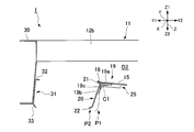
図3に示すように、天板15の前端部には、上方Z1に向かうにしたがって前方Y1に突出するように傾いた当接片16が取付けられている。天板15及び当接片16は、例えば金属製の板材を折り曲げること等により形成されている。
図3及び図4に示すように、天板15の下面には、複数の着脱用ヒンジ19(本実施形態では、例えば3つの着脱用ヒンジ19)が取付けられている。各着脱用ヒンジ19は、第一着脱腕部19aと、第二着脱腕部19bと、を有している。着脱用ヒンジ19は、第一着脱腕部19aと第二着脱腕部19bとのなす角度を調節可能である。両着脱腕部19a、19bは、ステンレス鋼等の金属で形成することができる。
第一着脱腕部19aは、前後方向Yに延びるように配置され、天板15の前端部に図示しないネジ部材等により取付けられている。第二着脱腕部19bは、第一着脱腕部19aの前端部から下方Z2に延びている。第二着脱腕部19bは、第一着脱腕部19aに対して左右方向Xに沿う軸線C1周りに回転移動することが可能である。
各着脱用ヒンジ19は、第一着脱腕部19aに対して第二着脱腕部19bを前方Y1に付勢する着脱バネ(付勢部材)19cを有している。
複数の着脱用ヒンジ19は、左右方向Xに間隔を空けて並べて配置されている。
図3及び図4に示すように、天板15の下面には、複数の着脱用ヒンジ19(本実施形態では、例えば3つの着脱用ヒンジ19)が取付けられている。各着脱用ヒンジ19は、第一着脱腕部19aと、第二着脱腕部19bと、を有している。着脱用ヒンジ19は、第一着脱腕部19aと第二着脱腕部19bとのなす角度を調節可能である。両着脱腕部19a、19bは、ステンレス鋼等の金属で形成することができる。
第一着脱腕部19aは、前後方向Yに延びるように配置され、天板15の前端部に図示しないネジ部材等により取付けられている。第二着脱腕部19bは、第一着脱腕部19aの前端部から下方Z2に延びている。第二着脱腕部19bは、第一着脱腕部19aに対して左右方向Xに沿う軸線C1周りに回転移動することが可能である。
各着脱用ヒンジ19は、第一着脱腕部19aに対して第二着脱腕部19bを前方Y1に付勢する着脱バネ(付勢部材)19cを有している。
複数の着脱用ヒンジ19は、左右方向Xに間隔を空けて並べて配置されている。
各着脱用ヒンジ19の第二着脱腕部19bには、第二側板(第二当接部材)20が、図示しないリベットや接着剤等で取付けられている。第二側板20は、後述するように第一側板31とともに整流部材36を前後方向Yに挟み第二側板20が整流部材36に当接した第一当接位置P1にあるときには、上下方向Z及び左右方向Xにそれぞれ延びている。
第二側板20は、整流部材36の第二端、すなわち整流部材36よりも後方Y2に配置されている。着脱用ヒンジ19の第二着脱腕部19bが軸線C1周りに回転移動することで、第二側板20も軸線C1周りに回転移動(可動)する。これにより、第二側板20は、整流部材36に接近したり整流部材36から離間したりするように可動する。
第二側板20の上端部には、前方Y1に延びる当接片21が取付けられている。なお、この当接片21及び天板15の当接片16で、後述する第二当接位置P2よりも前方Y1に、第二側板20が可動(移動)するのを規制する移動範囲規制部23を構成する。当接片21と天板15の当接片16との間には、隙間S1が形成されている。
第二側板20は、整流部材36の第二端、すなわち整流部材36よりも後方Y2に配置されている。着脱用ヒンジ19の第二着脱腕部19bが軸線C1周りに回転移動することで、第二側板20も軸線C1周りに回転移動(可動)する。これにより、第二側板20は、整流部材36に接近したり整流部材36から離間したりするように可動する。
第二側板20の上端部には、前方Y1に延びる当接片21が取付けられている。なお、この当接片21及び天板15の当接片16で、後述する第二当接位置P2よりも前方Y1に、第二側板20が可動(移動)するのを規制する移動範囲規制部23を構成する。当接片21と天板15の当接片16との間には、隙間S1が形成されている。
図5に示すように、第二側板20の前方Y1に整流部材36が配置されていない場合には、第二着脱腕部19bは着脱バネ19cの付勢力により前方Y1に可動する。このとき、第二側板20は前述の第一当接位置P1よりも前方Y1の第二当接位置P2に可動する。第二当接位置P2は、第一当接位置P1よりも第一側板31に近付いた位置である。第二側板20の当接片21が天板15の当接片16に当接することで、第二側板20は第二当接位置P2よりも前方Y1に可動するのが規制される。言い換えれば、第二側板20は第二当接位置P2よりも第一側板31に近付くのが規制される。
図3に示すように、第二側板20には、第二側板20における後述する整流部材36が当接する当接面20aの下端部から前方Y1に突出する第二突部(突部)22が設けられている。第二突部22は、第一側板31に近付くように突出する。第二突部22は、前方Y1に向かうにしたがって下方Z2に突出するように傾いている。
第二側板20、当接片21、及び第二突部22は、金属製の板材を折り曲げること等により一体に形成されている。
第二側板20が第一当接位置P1にあるときには、当接片21は天板15の当接片16から下方Z2に離間している。
第二側板20、当接片21、及び第二突部22は、金属製の板材を折り曲げること等により一体に形成されている。
第二側板20が第一当接位置P1にあるときには、当接片21は天板15の当接片16から下方Z2に離間している。
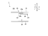
図3及び図4に示すように、天板15の下面には、1つのストッパヒンジ(ヒンジ、離間規制部)25が取付けられている。ストッパヒンジ25は、第一ストッパ腕部(第一腕部)25aと、第二ストッパ腕部(第二腕部)25bと、を有している。ストッパヒンジ25は、第一ストッパ腕部25aと第二ストッパ腕部25bとのなす角度を調節可能である。両ストッパ腕部25a、25bは、ステンレス鋼等の金属で形成することができる。
第一ストッパ腕部25aは、前後方向Yに延びるように配置され、天板15の前端部に図示しないネジ部材等により取付けられている。
第二ストッパ腕部25bは、外力が作用しない自然状態では第二ストッパ腕部25bに作用する重力(自重)により第一ストッパ腕部25aから下方Z2に垂れ下がっている。
この状態が、ストッパヒンジ25が開いた第一状態P6である。第二ストッパ腕部25bは、第一ストッパ腕部25aに対して前後方向Yに沿う軸線C2周りに回転可能である。
第一ストッパ腕部25aは、前後方向Yに延びるように配置され、天板15の前端部に図示しないネジ部材等により取付けられている。
第二ストッパ腕部25bは、外力が作用しない自然状態では第二ストッパ腕部25bに作用する重力(自重)により第一ストッパ腕部25aから下方Z2に垂れ下がっている。
この状態が、ストッパヒンジ25が開いた第一状態P6である。第二ストッパ腕部25bは、第一ストッパ腕部25aに対して前後方向Yに沿う軸線C2周りに回転可能である。
第二ストッパ腕部25bには、第二ストッパ腕部25bよりも下方Z2(回転の軸線C2の径方向外側)に突出する延長部材26が取付けられている。延長部材26は、樹脂等で板状に形成されている。延長部材26と第二ストッパ腕部25bとは、リベット等の接続部材27で固定されている。
ストッパヒンジ25は、例えば3つの着脱用ヒンジ19のうち中央に配置された着脱用ヒンジ19に対して左右方向Xに隣り合うように配置されている。
ストッパヒンジ25は、例えば3つの着脱用ヒンジ19のうち中央に配置された着脱用ヒンジ19に対して左右方向Xに隣り合うように配置されている。
ストッパヒンジ25が開いた第一状態P6にあるときに、第一当接位置P1にある第二側板20の背面に延長部材26が直交するように当接する。これにより、ストッパヒンジ25は第二側板20が後方Y2に(整流部材36から離間するように)可動するのを規制する。
図3に示すように、このときの延長部材26の下端部は、第二突部22の下端部に等しい高さか、第二突部22の下端部よりも上方Z1に配置されていることが好ましい。このように構成されることで、ショーケース1内に商品を入れる際に延長部材26が支障となりにくくなる。
図3に示すように、このときの延長部材26の下端部は、第二突部22の下端部に等しい高さか、第二突部22の下端部よりも上方Z1に配置されていることが好ましい。このように構成されることで、ショーケース1内に商品を入れる際に延長部材26が支障となりにくくなる。
一方で、図6に示すように、第二ストッパ腕部25bに作用する重力に抗して、作業者が手で第二ストッパ腕部25bを軸線C2周りに回転させ、第二ストッパ腕部25b及び延長部材26が左右方向Xに延びる向きになるように配置する。すなわち、第二ストッパ腕部25b及び延長部材26が水平になるように押し上げる。この状態が、ストッパヒンジ25が閉じた第二状態P7である。このとき、延長部材26は第二側板20に当接しないため、ストッパヒンジ25は第二側板20が後方Y2に(整流部材36から離間するように)可動するのを許容する。作業者が第二ストッパ腕部25bから手を放すと、第二ストッパ腕部25bは自重により下方Z2に垂れ下がる。
このように、作業者が第二ストッパ腕部25bを操作することで、ストッパヒンジ25は第一状態P6と第二状態P7とに切替え可能である。
このように、作業者が第二ストッパ腕部25bを操作することで、ストッパヒンジ25は第一状態P6と第二状態P7とに切替え可能である。
図3に示すように、上部断熱壁12bよりも前方Y1には、支持部材30が配置されている。支持部材30の上端部は、上部断熱壁12bに取付けられている。支持部材30は、上部ダクトD2の前方Y1を封止している。
支持部材30の後端部には、第一側板(第一当接部材)31が取付けられている。第一側板31は、上下方向Z及び左右方向Xにそれぞれ延びている。第一側板31は、整流部材36を挟んで第二側板20に対向するように配置されている。
第一側板31の上端部には、後方Y2に延びる当接片32が取付けられている。第一側板31には、第一側板31における整流部材36が当接する当接面31aの下端部から後方Y2に突出する第一突部33が設けられている。
支持部材30の後端部には、第一側板(第一当接部材)31が取付けられている。第一側板31は、上下方向Z及び左右方向Xにそれぞれ延びている。第一側板31は、整流部材36を挟んで第二側板20に対向するように配置されている。
第一側板31の上端部には、後方Y2に延びる当接片32が取付けられている。第一側板31には、第一側板31における整流部材36が当接する当接面31aの下端部から後方Y2に突出する第一突部33が設けられている。
第一側板31と、第一当接位置P1にある第二側板20との間には、ハニカム状の整流部材36が配置されている。整流部材36には、上下方向Zに延びる貫通孔36aが多数形成されている。整流部材36は、樹脂等で形成することができる。整流部材36は、ショーケース1内を流れる空気を整流する。第一側板31は、整流部材36に整流部材36の前方Y1の第一端で当接する。第二側板20は、整流部材36に整流部材36の後方Y2で当接する。側板31、20は、整流部材36を挟むように整流部材36に当接している。着脱バネ19cは、第二側板20が第一側板31とともに整流部材36を挟むように第二側板20を前方Y1に付勢する。
整流部材36は、下方Z2を第一突部33及び第二突部22により支持されている。整流部材36は、上方Z1を当接片32、21により保持されている。
整流部材36は、下方Z2を第一突部33及び第二突部22により支持されている。整流部材36は、上方Z1を当接片32、21により保持されている。
図3に示すように、支持部材30には、連結部材39、40を介して支持部41が取付けられている。連結部材39の下部には、切欠き39aが形成されている。支持部41は、左右方向Xに見たときにC字形に形成されている。支持部41は、C字形の開口を広げたり狭めたりするように変形させることができる。支持部41には、LED42が保持されている。LED42は、左右方向Xに延びるように配置されている。LED42の両端部には、ソケット43が取付けられている。ソケット43には、リード線44の端部が接続されている。
支持部材30には、照明カバー46の上端部がネジ部材47により固定されている。照明カバー46の下端部は、連結部材39の切欠き39aに係止されている。
支持部材30には、照明カバー46の上端部がネジ部材47により固定されている。照明カバー46の下端部は、連結部材39の切欠き39aに係止されている。
図2に示すように、後板13の下端部には、前方Y1に延びる底板51が取付けられている。底板51と下部断熱壁12cとの間には、熱交換室D3が形成される。熱交換室D3は、後部ダクトD1に連通する。後板13、天板15、及び底板51の間には、前方Y1が開口する陳列空間S3が形成される。すなわち、ショーケース1において陳列空間S3が開口している方向が前方Y1である。
後板13には、上下方向Zに延びる支柱53が取付けられている。この支柱53には、図示はしないが、上下方向Zに間隔を空けて複数の連通孔が形成されている。支柱53には、複数の陳列棚54が着脱可能に取付けられている。陳列棚54のフック54aを係合させる支柱53の連通孔の位置を変えることで、支柱53に対する陳列棚54の上下方向Zの位置を変更させることができる。
複数の陳列棚54は、陳列空間S3を上下方向Zに区画する。
後板13には、上下方向Zに延びる支柱53が取付けられている。この支柱53には、図示はしないが、上下方向Zに間隔を空けて複数の連通孔が形成されている。支柱53には、複数の陳列棚54が着脱可能に取付けられている。陳列棚54のフック54aを係合させる支柱53の連通孔の位置を変えることで、支柱53に対する陳列棚54の上下方向Zの位置を変更させることができる。
複数の陳列棚54は、陳列空間S3を上下方向Zに区画する。
断熱壁12は、鉄板等で形成された基台57で支持されている。底板51の前端部と基台57との間には、吸込口58が形成されている。吸込口58は、熱交換室D3に連通する。熱交換室D3は、仕切り板59で仕切られている。仕切り板59に形成された図示しない孔部には、送風機60が取付けられている。
熱交換室D3と後部ダクトD1とが連通する部分には、冷却器61が取付けられている。冷却器61は、ショーケース1の外部に設けられた、圧縮機や凝縮器等を有する図示しない冷凍回路に接続されている。冷却器61内には、冷凍回路により冷却された冷媒が流れる。
熱交換室D3と後部ダクトD1とが連通する部分には、冷却器61が取付けられている。冷却器61は、ショーケース1の外部に設けられた、圧縮機や凝縮器等を有する図示しない冷凍回路に接続されている。冷却器61内には、冷凍回路により冷却された冷媒が流れる。
側板66は、前方Y1が開口するC字形に形成された仕切り板67と、仕切り板67の凹部に取付けられた窓部68と、を有する。窓部68は、ガラス等の透明な材料で形成されている。
窓部68を通して、陳列空間S3を左右方向Xから視認することができる。
窓部68を通して、陳列空間S3を左右方向Xから視認することができる。
ショーケース1は制御部71を備えている。制御部71には、前述のソケット43のリード線44及び送風機60が接続されている。LED42及び送風機60は、制御部71に制御される。
次に、以上のように構成されたショーケース1の動作について説明する。
冷凍回路で冷やされた冷媒より、冷却器61が冷却される。ショーケース1を起動すると、制御部71は、リード線44及びソケット43を介してLED42に電力を供給し、LED42を点灯させる。LED42が発した照明光は、各陳列棚54等に照射される。
制御部71が送風機60に電力を供給すると、送風機60は、図2に示すように空気A1を流す。この空気A1は冷却器61で冷却される。冷却された空気A2の一部は、後部ダクトD1、上部ダクトD2、及び整流部材36を通って下方Z2に向かって流れる空気A3となる。整流部材36の多数の貫通孔36a内を通る際に、空気A3は整流される。
空気A3が整流部材36を通る際に、整流部材36に埃が溜まる。
各陳列棚54の前方Y1を下方Z2に向かって流れる空気A3は、陳列空間S3内の空気が外部に流れ出るのを防止する。
冷凍回路で冷やされた冷媒より、冷却器61が冷却される。ショーケース1を起動すると、制御部71は、リード線44及びソケット43を介してLED42に電力を供給し、LED42を点灯させる。LED42が発した照明光は、各陳列棚54等に照射される。
制御部71が送風機60に電力を供給すると、送風機60は、図2に示すように空気A1を流す。この空気A1は冷却器61で冷却される。冷却された空気A2の一部は、後部ダクトD1、上部ダクトD2、及び整流部材36を通って下方Z2に向かって流れる空気A3となる。整流部材36の多数の貫通孔36a内を通る際に、空気A3は整流される。
空気A3が整流部材36を通る際に、整流部材36に埃が溜まる。
各陳列棚54の前方Y1を下方Z2に向かって流れる空気A3は、陳列空間S3内の空気が外部に流れ出るのを防止する。
空気A3は、吸込口58を通って熱交換室D3内に流れ込み、送風機60により再び冷却器61に向かって流れる。
後部ダクトD1内を流れる冷却された空気A2の残部は、後板13の吹出し口から前方Y1に流れ、陳列空間S3内を冷却する。
後部ダクトD1内を流れる冷却された空気A2の残部は、後板13の吹出し口から前方Y1に流れ、陳列空間S3内を冷却する。
ショーケース1を一定時間動作させたら、ショーケース1を停止させて整流部材36を以下に説明するように清掃する。予め、ストッパヒンジ25の第二ストッパ腕部25bは自重により下方Z2に垂れ下がっていて、ストッパヒンジ25は開いた第一状態P6になっている。
まず、作業者は、例えば左手で延長部材26を操作し、図6に示すように、ストッパヒンジ25の第二ストッパ腕部25bが水平になるように押し上げる。これにより、ストッパヒンジ25を閉じた第二状態P7にする。作業者は、左手でこの状態を保持しておく。
まず、作業者は、例えば左手で延長部材26を操作し、図6に示すように、ストッパヒンジ25の第二ストッパ腕部25bが水平になるように押し上げる。これにより、ストッパヒンジ25を閉じた第二状態P7にする。作業者は、左手でこの状態を保持しておく。
次に、図7に示すように、着脱バネ19cの付勢力に抗して、第二側板20を例えば右手で後方Y2に可動させる。第二側板20が整流部材36から離間し、整流部材36が下方Z2に落ちる。作業者は、例えば左手をストッパヒンジ25から放し、左手で整流部材36を支える。第二側板20から右手を離すと、図5に示すように第二側板20は着脱バネ19cの付勢力により前方Y1に可動する。しかし、移動範囲規制部23の当接片16に当接片21が当接して第二側板20が第二当接位置P2に可動すると、第二側板20は第二当接位置P2よりも前方Y1に可動できなくなる。
ストッパヒンジ25の第二ストッパ腕部25bは自重により垂れ下がり、ストッパヒンジ25は開いた第一状態P6になる。
ストッパヒンジ25の第二ストッパ腕部25bは自重により垂れ下がり、ストッパヒンジ25は開いた第一状態P6になる。
整流部材36を清掃し、整流部材36から埃等を取り除く。なお、整流部材36を新しい整流部材36に交換してもよい。
作業者は、例えば左手で延長部材26を操作し、第二ストッパ腕部25bが水平になるように押し上げる。これにより、ストッパヒンジ25を閉じた第二状態P7にする。作業者は、左手でこの状態を保持しておく。
次に、着脱バネ19cの付勢力に抗して、第二側板20を右手で図7程度まで後方Y2に可動させ、この状態を保持する。ここで、延長部材26から左手を離しても、第二ストッパ腕部25bが第二側板20に下方Z2から支持されることで、第二ストッパ腕部25bが垂れ下がらない。このため、ストッパヒンジ25が第一状態P6にならない。
作業者は、例えば左手で延長部材26を操作し、第二ストッパ腕部25bが水平になるように押し上げる。これにより、ストッパヒンジ25を閉じた第二状態P7にする。作業者は、左手でこの状態を保持しておく。
次に、着脱バネ19cの付勢力に抗して、第二側板20を右手で図7程度まで後方Y2に可動させ、この状態を保持する。ここで、延長部材26から左手を離しても、第二ストッパ腕部25bが第二側板20に下方Z2から支持されることで、第二ストッパ腕部25bが垂れ下がらない。このため、ストッパヒンジ25が第一状態P6にならない。
左手で第一側板31と第二側板20との間に整流部材36を配置し、右手で第二側板20を前方Y1に可動させる。このとき、当接片21、32に下方Z2から整流部材36を当接させることで、整流部材36の上下方向Zの位置決めが容易になる。
作業者は、第二側板20から右手を放す。着脱バネ19cの付勢力により、両側板31、20が整流部材36に当接する。着脱バネ19cの付勢力により第二側板20が整流部材36から離間しにくくなり、整流部材36が意図することなく外れるのが確実に抑えられる。
ストッパヒンジ25の第二ストッパ腕部25bは自重により垂れ下がり、ストッパヒンジ25は開いた第一状態P6になる。第一側板31に第一突部33、第二側板20に第二突部22がそれぞれ設けられているため、第一側板31と第二側板20との間から整流部材36が落ちにくくなる。
作業者が誤って第二側板20に触れても、ストッパヒンジ25が第一状態P6であるため、ショーケース1から整流部材36が外れない。
作業者は、第二側板20から右手を放す。着脱バネ19cの付勢力により、両側板31、20が整流部材36に当接する。着脱バネ19cの付勢力により第二側板20が整流部材36から離間しにくくなり、整流部材36が意図することなく外れるのが確実に抑えられる。
ストッパヒンジ25の第二ストッパ腕部25bは自重により垂れ下がり、ストッパヒンジ25は開いた第一状態P6になる。第一側板31に第一突部33、第二側板20に第二突部22がそれぞれ設けられているため、第一側板31と第二側板20との間から整流部材36が落ちにくくなる。
作業者が誤って第二側板20に触れても、ストッパヒンジ25が第一状態P6であるため、ショーケース1から整流部材36が外れない。
以上説明したように、本実施形態のショーケース1によれば、作業者は、ストッパヒンジ25を閉じた第二状態P7にし、第二側板20を後方Y2に可動して第二側板20を整流部材36から離間させてから、ショーケース1から整流部材36を取外す。一方で、ストッパヒンジ25を開いた第一状態P6にすると第二側板20が後方Y2に可動できなくなるため、誤って第二側板20に触れてもショーケース1から整流部材36が外れる恐れはない。
したがって、整流部材36が意図することなく外れるのを抑えることができる。
したがって、整流部材36が意図することなく外れるのを抑えることができる。
ショーケース1が着脱バネ19cを備えることで、第二側板20が整流部材36から離間しにくくなり、整流部材36が意図することなく外れるのをより確実に抑えることができる。
ストッパヒンジ25の第二ストッパ腕部25bから手を放すだけで、第二ストッパ腕部25bが自重により下方Z2に垂れ下がり、ストッパヒンジ25を開いた第一状態P6にすることができる。第一状態P6のストッパヒンジ25は、第二ストッパ腕部25bが自重により垂れ下がっているだけで、第二ストッパ腕部25bにバネ等の付勢力は作用していないため、第二ストッパ腕部25bを押し上げてストッパヒンジ25を容易に閉じた第二状態P7にすることができる。
ストッパヒンジ25の第二ストッパ腕部25bから手を放すだけで、第二ストッパ腕部25bが自重により下方Z2に垂れ下がり、ストッパヒンジ25を開いた第一状態P6にすることができる。第一状態P6のストッパヒンジ25は、第二ストッパ腕部25bが自重により垂れ下がっているだけで、第二ストッパ腕部25bにバネ等の付勢力は作用していないため、第二ストッパ腕部25bを押し上げてストッパヒンジ25を容易に閉じた第二状態P7にすることができる。
第二側板20に第二突部22が設けられていることで、第一側板31と第二側板20との間から整流部材36が落ちるのを抑制することができる。
ショーケース1が移動範囲規制部23を備えることで、ショーケース1から整流部材36を取外した後で第二側板20が前方Y1に可動し過ぎてショーケース1に整流部材36を取付けにくくなるのを抑えることができる。
ショーケース1が移動範囲規制部23を備えることで、ショーケース1から整流部材36を取外した後で第二側板20が前方Y1に可動し過ぎてショーケース1に整流部材36を取付けにくくなるのを抑えることができる。
なお、本実施形態では、着脱用ヒンジ19は着脱バネ19cを備えなくてもよい。ストッパヒンジ25を開いた第一状態P6にすることで、ショーケース1から整流部材36が外れなくなるためである。
離間規制部として、第一ストッパ腕部25aが天板15に取付けられたストッパヒンジ25を用いた。しかし、離間規制部の構成はこれに限定されない。
例えば、このストッパヒンジ25の第一ストッパ腕部25aを第二側板20の後面に取付けてもよい。開いた状態のストッパヒンジ25の第二ストッパ腕部25bが天板15に直交するように当接することで、ストッパヒンジ25は、第一当接位置P1にある第二側板20が後方Y2に可動するのを規制する第一状態になる。一方で、ストッパヒンジ25が閉じたときに、第二ストッパ腕部25bが天板15に当接してもそのときの第二ストッパ腕部25bが天板15に略平行になっている。このため、ストッパヒンジ25は、第一当接位置P1にある第二側板20が後方Y2に可動するのを許容する第二状態になる。
例えば、このストッパヒンジ25の第一ストッパ腕部25aを第二側板20の後面に取付けてもよい。開いた状態のストッパヒンジ25の第二ストッパ腕部25bが天板15に直交するように当接することで、ストッパヒンジ25は、第一当接位置P1にある第二側板20が後方Y2に可動するのを規制する第一状態になる。一方で、ストッパヒンジ25が閉じたときに、第二ストッパ腕部25bが天板15に当接してもそのときの第二ストッパ腕部25bが天板15に略平行になっている。このため、ストッパヒンジ25は、第一当接位置P1にある第二側板20が後方Y2に可動するのを許容する第二状態になる。
離間規制部として、上下方向Zに沿う軸線周りに回転可能な切替え部材を用いてもよい。この切替え部材は、上下方向Zに見たときに非円形状の矩形等に形成されることが好ましい。切替え部材の軸線周りの位置を調節して切替え部材が第一当接位置P1にある第二側板20に当接したときに、切替え部材は第二側板20が後方Y2に可動するのを規制する第一状態になる。
一方で、切替え部材が第一当接位置P1にある第二側板20に当接しないときに、切替え部材は第二側板20が後方Y2に可動するのを許容する第二状態になる。
一方で、切替え部材が第一当接位置P1にある第二側板20に当接しないときに、切替え部材は第二側板20が後方Y2に可動するのを許容する第二状態になる。
側板31、20が整流部材36を前後方向Yに挟む力が十分に強い場合等には、側板31、20には突部33、22は設けられなくてもよい。
着脱バネ19cが伸びきる状態になるときの第二側板20の位置が、第一当接位置P1よりもわずかに前方Y1である場合等には、ショーケース1は移動範囲規制部23、すなわち当接片16、21を備えなくてもよい。
着脱バネ19cが伸びきる状態になるときの第二側板20の位置が、第一当接位置P1よりもわずかに前方Y1である場合等には、ショーケース1は移動範囲規制部23、すなわち当接片16、21を備えなくてもよい。
前記実施形態では、第二側板20が軸線C1周りに回転移動することで、第一側板31及び第二側板20が整流部材36を前後方向Yに挟むとした。しかし、第二側板20が前後方向Yに平行移動することで、第一側板31及び第二側板20が整流部材36を前後方向Yに挟むとしてもよい。この場合、例えば、天板15に前後方向Yに延びるレールを設け、このレールに沿って第二側板20を可動させる。
実施形態では、移動範囲規制部23は、第二側板20が第二当接位置P2よりも前方Y1に可動するのを規制した。しかし、移動範囲規制部は、第二側板20が第一当接位置P1よりも前方Y1に可動するのを規制してもよい。
実施形態では、移動範囲規制部23は、第二側板20が第二当接位置P2よりも前方Y1に可動するのを規制した。しかし、移動範囲規制部は、第二側板20が第一当接位置P1よりも前方Y1に可動するのを規制してもよい。
以上説明した少なくともひとつの実施形態によれば、ストッパヒンジ25を持つことにより、整流部材36が意図することなく外れるのを抑えることができる。
本発明のいくつかの実施形態を説明したが、これらの実施形態は、例として提示したものであり、発明の範囲を限定することは意図していない。これら実施形態は、その他の様々な形態で実施されることが可能であり、発明の要旨を逸脱しない範囲で、種々の省略、置き換え、変更を行うことができる。これら実施形態やその変形は、発明の範囲や要旨に含まれると同様に、特許請求の範囲に記載された発明とその均等の範囲に含まれるものである。
1…ショーケース、19c…着脱バネ(付勢部材)、20…第二側板(第二当接部材)、22…第二突部(突部)、23…移動範囲規制部、25…ストッパヒンジ(ヒンジ、離間規制部)、25a…第一ストッパ腕部(第一腕部)、25b…第二ストッパ腕部(第二腕部)、31…第一側板(第一当接部材)、36…整流部材、P1…第一当接位置、P2…第二当接位置、P6…第一状態、P7…第二状態、Z2…下方
Claims (5)
- ショーケース内を流れる空気を整流する整流部材に前記整流部材の第一端で当接する第一当接部材と、
前記整流部材の第二端に配置され、前記整流部材から離間するように可動する第二当接部材と、
前記第一当接部材とともに前記整流部材を挟むように前記整流部材に当接した前記第二当接部材が前記整流部材から離間するように可動するのを規制する第一状態と、前記第二当接部材が前記整流部材から離間するように可動するのを許容する第二状態と、に切替え可能な離間規制部と、
を備えるショーケース。 - 前記第二当接部材が前記第一当接部材とともに前記整流部材を挟むように前記第二当接部材を付勢する付勢部材を備える請求項1に記載のショーケース。
- 前記離間規制部は、第一腕部と第二腕部とのなす角度を調節可能なヒンジであり、
前記第二腕部に重力が作用して前記第二腕部が前記第一腕部から垂れ下がったときに、前記離間規制部が前記第一状態になる請求項1又は2に記載のショーケース。 - 前記第二当接部材には、前記第二当接部材における前記整流部材が当接する当接面の下方の端部から前記第一当接部材に近付くように突出する突部が設けられている請求項1から3のいずれか一項に記載のショーケース。
- 前記第二当接部材が前記整流部材に当接した第一当接位置、又は前記第一当接位置よりも前記第一当接部材に近付いた第二当接位置、よりも前記第一当接部材に近付くように、前記第二当接部材が可動するのを規制する移動範囲規制部を備える請求項1から4のいずれか一項に記載のショーケース。
Priority Applications (1)
| Application Number | Priority Date | Filing Date | Title |
|---|---|---|---|
| JP2018523965A JPWO2017221785A1 (ja) | 2016-06-21 | 2017-06-14 | ショーケース |
Applications Claiming Priority (2)
| Application Number | Priority Date | Filing Date | Title |
|---|---|---|---|
| JP2016123012 | 2016-06-21 | ||
| JP2016-123012 | 2016-06-21 |
Publications (1)
| Publication Number | Publication Date |
|---|---|
| WO2017221785A1 true WO2017221785A1 (ja) | 2017-12-28 |
Family
ID=60784757
Family Applications (1)
| Application Number | Title | Priority Date | Filing Date |
|---|---|---|---|
| PCT/JP2017/021971 Ceased WO2017221785A1 (ja) | 2016-06-21 | 2017-06-14 | ショーケース |
Country Status (2)
| Country | Link |
|---|---|
| JP (1) | JPWO2017221785A1 (ja) |
| WO (1) | WO2017221785A1 (ja) |
Citations (4)
| Publication number | Priority date | Publication date | Assignee | Title |
|---|---|---|---|---|
| JPS561076U (ja) * | 1979-06-19 | 1981-01-07 | ||
| JPS6360871U (ja) * | 1986-10-06 | 1988-04-22 | ||
| US4807446A (en) * | 1986-01-24 | 1989-02-28 | Sanden Corporation | Air outlet nozzles for an air circulation device in a refrigerated display cabinet |
| JPH07110187A (ja) * | 1993-10-14 | 1995-04-25 | Sanyo Electric Co Ltd | ショーケース等の部品取付用装置 |
-
2017
- 2017-06-14 JP JP2018523965A patent/JPWO2017221785A1/ja active Pending
- 2017-06-14 WO PCT/JP2017/021971 patent/WO2017221785A1/ja not_active Ceased
Patent Citations (4)
| Publication number | Priority date | Publication date | Assignee | Title |
|---|---|---|---|---|
| JPS561076U (ja) * | 1979-06-19 | 1981-01-07 | ||
| US4807446A (en) * | 1986-01-24 | 1989-02-28 | Sanden Corporation | Air outlet nozzles for an air circulation device in a refrigerated display cabinet |
| JPS6360871U (ja) * | 1986-10-06 | 1988-04-22 | ||
| JPH07110187A (ja) * | 1993-10-14 | 1995-04-25 | Sanyo Electric Co Ltd | ショーケース等の部品取付用装置 |
Also Published As
| Publication number | Publication date |
|---|---|
| JPWO2017221785A1 (ja) | 2019-04-11 |
Similar Documents
| Publication | Publication Date | Title |
|---|---|---|
| JP2012236437A (ja) | 車両用空調装置 | |
| JP2016020766A (ja) | 空気調和機の室内機 | |
| WO2017221785A1 (ja) | ショーケース | |
| JP6589351B2 (ja) | デッキ | |
| CN101206054B (zh) | 空调器 | |
| EP2759781B1 (en) | Floor-standing indoor unit of air-conditioning apparatus | |
| JP2016144599A (ja) | ショーケース | |
| JP2009072282A (ja) | ショーケース | |
| JP2014145542A5 (ja) | ||
| JP2012172856A (ja) | 空気調和機 | |
| JP2014236782A (ja) | ショーケース | |
| JP5118924B2 (ja) | ショーケース | |
| JP5085191B2 (ja) | オープンショーケース | |
| JP2002209684A (ja) | ショーケースの商品棚 | |
| JP5736488B1 (ja) | フックおよびオープンショーケース | |
| JP6692143B2 (ja) | 収納箱の吊り下げ構造 | |
| KR20100066178A (ko) | 공기조화기 | |
| KR20130054626A (ko) | 공기조화시스템의 실내기 | |
| KR20080026810A (ko) | 공기조화기 | |
| JP2008206640A (ja) | オープンショーケース | |
| KR100767789B1 (ko) | 공기조화기의 디스플레이장치 | |
| KR20100043987A (ko) | 공기 조화기 | |
| JP5985445B2 (ja) | 空調システム | |
| JP6679827B2 (ja) | ショーケース | |
| CN215112263U (zh) | 一种安装架 |
Legal Events
| Date | Code | Title | Description |
|---|---|---|---|
| 121 | Ep: the epo has been informed by wipo that ep was designated in this application |
Ref document number: 17815254 Country of ref document: EP Kind code of ref document: A1 |
|
| ENP | Entry into the national phase |
Ref document number: 2018523965 Country of ref document: JP Kind code of ref document: A |
|
| NENP | Non-entry into the national phase |
Ref country code: DE |
|
| 122 | Ep: pct application non-entry in european phase |
Ref document number: 17815254 Country of ref document: EP Kind code of ref document: A1 |