WO2017217062A1 - 撮影画像判定装置 - Google Patents
撮影画像判定装置 Download PDFInfo
- Publication number
- WO2017217062A1 WO2017217062A1 PCT/JP2017/011926 JP2017011926W WO2017217062A1 WO 2017217062 A1 WO2017217062 A1 WO 2017217062A1 JP 2017011926 W JP2017011926 W JP 2017011926W WO 2017217062 A1 WO2017217062 A1 WO 2017217062A1
- Authority
- WO
- WIPO (PCT)
- Prior art keywords
- captured image
- synchronization signal
- unit
- display
- divided
- Prior art date
- Legal status (The legal status is an assumption and is not a legal conclusion. Google has not performed a legal analysis and makes no representation as to the accuracy of the status listed.)
- Ceased
Links
Images



Classifications
-
- H—ELECTRICITY
- H04—ELECTRIC COMMUNICATION TECHNIQUE
- H04N—PICTORIAL COMMUNICATION, e.g. TELEVISION
- H04N5/00—Details of television systems
- H04N5/04—Synchronising
- H04N5/08—Separation of synchronising signals from picture signals
- H04N5/10—Separation of line synchronising signal from frame synchronising signal or vice versa
-
- H—ELECTRICITY
- H04—ELECTRIC COMMUNICATION TECHNIQUE
- H04N—PICTORIAL COMMUNICATION, e.g. TELEVISION
- H04N7/00—Television systems
- H04N7/18—Closed-circuit television [CCTV] systems, i.e. systems in which the video signal is not broadcast
-
- B—PERFORMING OPERATIONS; TRANSPORTING
- B60—VEHICLES IN GENERAL
- B60R—VEHICLES, VEHICLE FITTINGS, OR VEHICLE PARTS, NOT OTHERWISE PROVIDED FOR
- B60R2300/00—Details of viewing arrangements using cameras and displays, specially adapted for use in a vehicle
- B60R2300/80—Details of viewing arrangements using cameras and displays, specially adapted for use in a vehicle characterised by the intended use of the viewing arrangement
- B60R2300/806—Details of viewing arrangements using cameras and displays, specially adapted for use in a vehicle characterised by the intended use of the viewing arrangement for aiding parking
-
- H—ELECTRICITY
- H04—ELECTRIC COMMUNICATION TECHNIQUE
- H04N—PICTORIAL COMMUNICATION, e.g. TELEVISION
- H04N17/00—Diagnosis, testing or measuring for television systems or their details
Definitions
- the present invention relates to a captured image determination device that determines display abnormality of a captured image captured by a camera.
- a captured image determination device that determines display abnormality of a captured image when driving an image by displaying a captured image of an in-vehicle camera on a monitor screen in a vehicle is known (for example, see Patent Document 1).
- color information at a predetermined sampling interval (for example, a predetermined number of times per second) set using a synchronization signal input to the display unit is added, and the added value for one second is the first value.
- the threshold value is smaller than 1, the display abnormality (black image state) is determined.
- the display abnormality is determined based on the addition value of the color signal for one second, even if the display abnormality of the entire captured image can be determined, a part of the captured image (for example, display anomalies of some horizontal lines) cannot be determined. As a result, the entire captured image must be hidden, which is inconvenient for driving assistance.
- the characteristic configuration of the photographed image determination device includes a synchronization signal extraction unit that extracts a vertical synchronization signal and a horizontal synchronization signal used to display a photographed image photographed by a camera, and a time for measuring a pulse interval time in the vertical synchronization signal.
- a measurement unit, a divided region setting unit configured to divide a frame of the captured image displayed in accordance with the pulse interval time with a virtual line in a horizontal direction and set a plurality of divided regions partitioned by the virtual line;
- a pulse number measurement unit that measures the number of pulses of the horizontal synchronization signal corresponding to the divided region, and whether or not an affirmative condition that the pulse number measured by the pulse number measurement unit is equal to or greater than a predetermined value is satisfied.
- a determination unit for determination is a determination unit for determination.
- a vertical synchronization signal and a horizontal synchronization signal that synchronize the output timing of a video signal are used to display an image captured by a camera on a monitor screen of a vehicle.
- the vertical synchronization signal and the horizontal synchronization signal are extracted, and determination is performed using the extracted vertical synchronization signal and horizontal synchronization signal.
- the determination is made not by using the color signal for each pixel but by using the horizontal synchronization signal set for each horizontal line on the frame, so that the amount of calculation can be reduced.
- the pulse interval time in the vertical synchronization signal is measured, and a divided region is set by dividing the frame of the captured image displayed according to the pulse interval time with a horizontal virtual line. Then, it is determined whether or not the number of pulses of the horizontal synchronizing signal corresponding to this divided area is equal to or greater than a predetermined value. That is, when the number of pulses of the horizontal synchronization signal corresponding to the divided area of the photographed image is less than a predetermined value, it is determined that a part of the horizontal line included in the divided area is not normally displayed.
- Another characteristic configuration includes a priority setting unit that sets a priority for displaying a plurality of the divided areas, and the determination unit sets the priority of the divided areas determined not to satisfy the positive condition to be equal to or lower than the priority.
- a non-display signal that does not display the captured image corresponding to the divided area is output.
- the priority order setting unit sets the priority order higher in the divided area below the captured image.
- Another characteristic configuration is that a masking signal for masking the divided area that does not satisfy the positive condition is output.
- the user can surely watch only the display area of the captured image on the monitor screen.
- the in-vehicle camera 1 uses a CCD (charge coupled device) or CIS (CMOS image sensor) or other imaging device to take a two-dimensional image of 15 to 30 frames per second in time series, digitally convert it into video data ( It is a camera that outputs a captured image PI) in real time.
- CCD charge coupled device
- CIS CMOS image sensor
- the in-vehicle camera 1 includes an optical unit 11 configured by a lens, an optical path, and the like, and a signal processing unit 12 configured by an image sensor, a signal processing circuit, a synchronization signal generation circuit, and the like.
- the lens is a wide-angle lens, and has a lens barrel (optical path) for preventing disturbance light entering from the lens to the light receiving surface of the image sensor.
- the signal processing unit 12 includes an image sensor that converts a scene around the vehicle into an analog image signal by photoelectric conversion, a signal processing circuit that converts the analog signal into a digital image signal by an A / D converter, a vertical synchronization signal, and a horizontal synchronization signal Is a semiconductor chip integrated with a synchronizing signal generating circuit for generating
- the digital image signal converted by the signal processing circuit includes a luminance signal and a color difference signal for each pixel, and the digital image signal is synchronized with the vertical synchronization signal and the horizontal synchronization signal to generate a captured image PI. .
- the vertical synchronization signal is composed of pulses having a rectangular waveform, and moves in the vertical direction of the captured image PI (moves from the lower right to the upper left of the screen) with one pulse. That is, the pulse interval time T of the vertical synchronization signal corresponds to the reciprocal of the frame rate of the captured image PI.
- the horizontal synchronization signal is composed of pulses having a rectangular waveform, and moves in the horizontal direction of the captured image PI (moves to the left end of the horizontal line immediately below) with one pulse. That is, the pulse number Pi of the horizontal synchronization signal corresponds to the number of video lines (horizontal lines) in the horizontal direction of the captured image PI.
- the frequency of the vertical synchronization signal is configured at 30 Hz
- the frequency of the horizontal synchronization signal is configured at 24 kHz. That is, the captured image PI is generated at 30 frames F per second, and 800 horizontal lines are generated for each frame F of the captured image PI.
- the captured image PI output by the signal processing unit 12 is subjected to correction processing by the image processing unit 2 and output as a display screen VI by the display unit 3. It has been described that the digital image signal converted by the signal processing unit 12 is synchronized with the vertical synchronization signal and the horizontal synchronization signal to generate the captured image PI. However, the captured image PI is displayed on the display screen. It will be in the state of VI. That is, in the present embodiment, the captured image PI subjected to the correction process is defined as the display screen VI, and the digital image signal converted by the signal processing unit 12 is displayed in synchronization with the vertical synchronization signal and the horizontal synchronization signal. A screen VI is generated.
- a display screen VI is generated by superimposing a guide image G on a captured image PI.
- the guide image G include an expected route C (dotted line display) that changes according to the steering angle of the vehicle, a vehicle extension line E (solid line display) drawn at a fixed position regardless of the steering angle.
- Information of various sensors including a steering sensor and a shift sensor is input to the image processing unit 2, and the position of the guide image G is changed according to the driving situation of the driver. As a result, the driver can smoothly park in the parking space while viewing the display screen VI.
- the display unit 3 is also used, for example, as a monitor device for a navigation system.
- This monitor device may be configured with, for example, a liquid crystal display, and may include a touch panel that can be operated by a tribar with a finger.
- the horizontal synchronization signal is not normally output, and image disturbance may occur in a part of the video.
- image disturbance occurs, a part of the image is lost, and there is a possibility that surrounding conditions such as obstacles cannot be accurately grasped.
- the display abnormality of a part of the captured image PI is efficiently detected using the captured image determination device X.
- the captured image determination device X includes a synchronization signal extraction unit 4, a calculation unit 6, and a determination unit 7.
- Each of these functional units is configured by a CPU that executes various processes, software having a memory as a core, or cooperation of hardware and software. Note that each functional unit does not have to have an independent physical configuration, and each function may be realized. That is, the functional units may be merged or may be incorporated in the signal processing unit 12. Each functional unit can be omitted as appropriate without departing from the gist of the present invention.
- the synchronization signal extraction unit 4 extracts a vertical synchronization signal and a horizontal synchronization signal used for displaying the captured image PI of the in-vehicle camera 1 on the display screen VI.
- the vertical synchronization signal and the horizontal synchronization signal are extracted as a pulse having a rectangular waveform for each frame F.
- the calculation unit 6 includes a time measurement unit 61, a divided region setting unit 62, and a pulse number measurement unit 63.
- the time measuring unit 61 measures a pulse interval time T in the vertical synchronization signal (see FIG. 1).
- This pulse interval time T is a time during which one frame F is displayed, and is set to 33.3 ms in this embodiment.
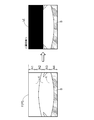
- the divided area setting unit 62 divides the frame F of the captured image PI displayed according to the pulse interval time T with the horizontal virtual line K, and sets a plurality of divided areas Ai partitioned by the virtual line K. (See FIG. 1).
- the divided areas Ai are arranged in parallel in the vertical direction of the frame F, and one divided area Ai has a divided synchronization time (T / N) obtained by dividing the pulse interval time T into four equal parts. Yes.
- the determination unit 7 determines whether or not an affirmative condition that the pulse number Pi of the horizontal synchronization signal for each divided region Ai measured by the pulse number measurement unit 63 is equal to or greater than a predetermined value is satisfied.
- a predetermined value for example, 195 lines
- the determination part 7 is comprised so that the display signal which displays the division area Ai which satisfies the affirmation condition in which each pulse number Pi of a horizontal synchronizing signal is more than predetermined value will be output to the image process part 2.
- FIG. Upon receiving this display signal, the image processing unit 2 generates the display screen VI by superimposing the guide image G or the like on the divided area Ai of the captured image PI to be displayed.
- the determination unit 7 does not determine by adding the luminance signal or color difference signal for each pixel, but uses the horizontal synchronization signal set for each horizontal line on the frame F. The amount of calculation can be reduced. Moreover, it is possible to easily grasp that an abnormality has occurred in the horizontal synchronization signal as the cause of the image disturbance.
- the captured image determination device X of the present embodiment includes a priority order setting unit 5 that sets a priority order for displaying the divided areas Ai on the display screen VI. Specifically, the priorities according to the driving conditions of the vehicle are mapped, and the priorities of the divided areas Ai are set for each frame F based on information from the sensor and the captured image PI. For example, when the vehicle is parking, that is, when the shift lever is in the R range, or the parking area and its surrounding image (parked vehicle, etc.) are shown in the captured image PI of the in-vehicle camera 1 (see FIG. 1), All the divided areas Ai are set to the same priority.
- the lower priority is set to the lower divided area Ai (as it goes from the divided area A1 to the divided area A4).
- the determination unit 7 is set to be equal to or lower than the priority order of the divided areas Ai that do not satisfy the positive condition that the number of pulses Pi of the horizontal synchronization signal is equal to or greater than a predetermined value.
- a non-display signal that does not display the divided area Ai (the captured image corresponding to the divided area Ai) is output to the image processing unit 2.
- the determination unit 7 outputs to the image processing unit 2 a masking signal for masking the divided area Ai (captured image corresponding to the divided area Ai) that does not satisfy the positive condition.
- the entire display screen VI becomes a black image in the state of FIG. 1, and the upper half of the display screen VI becomes a black image in the state of FIG.
- the driver can surely watch only the display area of the captured image PI on the display screen VI.
- the masking process is not limited to a black-painted image, and may be a white-painted image or a predetermined illustration.
- FIG. 1 for example, “Video is distorted. Please check the situation around the vehicle directly” is displayed on the display screen VI and / or by voice. Will do. As a result, the driver can safely confirm the surrounding situation without a sense of incongruity.
- the vertical synchronization signal is extracted to measure the pulse interval time T and the horizontal synchronization signal is extracted (# 44).
- the pulse interval time T is divided by a preset number N of divided areas to calculate a divided synchronization time (T / N) (# 45).
- the count number i is incremented to 1 (# 46), and the pulse of the horizontal synchronizing signal in the divided area A1 is detected (# 47).
- the display determination (# 53) subroutine will be described with reference to FIG. Priorities are set for the divided areas Ai for which an affirmative flag or a negative flag is set (# 530). Next, when there is no divided area Ai for which a negative flag is set (# 531N réelle determination), since the captured image PI is normal, the determination result is a display signal for displaying all the divided areas Ai (# 536).
- the divided area Aimax having the highest priority is selected (# 532).
- the priorities of the plurality of divided areas Ai are equal, the plurality of divided areas Ai are selected as the divided areas Aimax having the highest priority.
- the divided area Ai becomes a display signal (# 534).
- the determination result of the display determination subroutine (# 53) may be used for failure determination of the in-vehicle camera 1, and is not necessarily limited to the use for displaying the captured image PI of the in-vehicle camera 1 on the display screen VI.
- the number of divided areas Ai may be further finely divided within the range of the total number of pulses of the horizontal synchronization signal set in one frame F, and is not particularly limited. As the number of divided areas Ai increases, the display area and non-display area of the display screen VI are subdivided, and fine monitor display according to the driving situation can be realized. Further, the determination unit 7 sets an affirmative condition in which the number of pulses Pi of the horizontal synchronization signal for each divided region Ai is equal to a predetermined value (in the above-described embodiment, 200 horizontal synchronization signals that should originally exist in the divided region Ai). You may determine whether you are satisfied. In this case, more accurate determination can be performed.
- a predetermined value in the above-described embodiment, 200 horizontal synchronization signals that should originally exist in the divided region Ai
- the divided regions Ai need not be equally spaced.
- the area of the divided region Ai may be increased as the priority is higher.
- the display screen VI can be made easier to see.
- the display abnormality determination process is executed in real time every time a vertical synchronization signal is detected, but may be executed at predetermined intervals. In this case, the first determination result is applied until the next determination process is started.
- the time measuring unit 61 may measure from the pulse interval time T of the vertical synchronization signal predetermined for the in-vehicle camera 1.
- a storage unit that accumulates the determination result in the display abnormality determination process may be provided separately. In this case, the number of occurrences of display abnormality may be counted, and the driver may be informed that the vehicle-mounted camera 1 is faulty if the number of occurrences is equal to or greater than a predetermined number.
- the present invention can be used for a captured image determination device that determines a display abnormality when a captured image captured by an in-vehicle camera is displayed on a monitor screen of a vehicle.
Landscapes
- Engineering & Computer Science (AREA)
- Multimedia (AREA)
- Signal Processing (AREA)
- Health & Medical Sciences (AREA)
- Biomedical Technology (AREA)
- General Health & Medical Sciences (AREA)
- Closed-Circuit Television Systems (AREA)
- Mechanical Engineering (AREA)
- Testing, Inspecting, Measuring Of Stereoscopic Televisions And Televisions (AREA)
Abstract
撮影画像の一部の表示異常を効率的に検出できる撮影画像判定装置を提供する。カメラの撮影画像を表示するために用いられる垂直同期信号および水平同期信号を抽出する同期信号抽出部と、垂直同期信号におけるパルス間隔時間を計測する時間計測部と、パルス間隔時間に応じて表示される撮影画像のフレームを水平方向の仮想線で分割し、仮想線で区画された複数の分割領域を設定する分割領域設定部と、夫々の分割領域に対応する水平同期信号のパルス数を計測するパルス数計測部と、パルス数計測部で計測されたパルス数が所定値以上となる肯定条件を満足するか否かを判定する判定部と、を備えている。
Description
本発明は、カメラで撮影した撮影画像の表示異常を判定する撮影画像判定装置に関する。
従来、車載カメラの撮影画像を車内のモニター画面に表示して運転支援を行う際、撮影画像の表示異常を判定する撮影画像判定装置が知られている(例えば、特許文献1参照)。
特許文献1の撮影画像判定装置では、表示部に入力される同期信号を用いて設定された所定のサンプリング間隔(例えば1秒間に所定回数)の色情報を加算し、1秒間の加算値が第1の閾値よりも小さい場合に表示異常(黒画状態)と判定するものである。
しかしながら、従来の画像表示装置では、1秒間の色信号の加算値に基づいて表示異常を判定しているため、撮影画像全体の表示異常を判定することができても、撮影画像の一部(例えば、一部の水平ライン)の表示異常を判定することができない。その結果、撮影画像全体を非表示にせざるを得ず、運転支援をする上で使い勝手が悪い。
そこで、撮影画像の一部の表示異常を効率的に検出できる撮影画像判定装置が求められている。
撮影画像判定装置の特徴構成は、カメラで撮影した撮影画像を表示するために用いられる垂直同期信号および水平同期信号を抽出する同期信号抽出部と、前記垂直同期信号におけるパルス間隔時間を計測する時間計測部と、前記パルス間隔時間に応じて表示される前記撮影画像のフレームを水平方向の仮想線で分割し、当該仮想線で区画された複数の分割領域を設定する分割領域設定部と、夫々の前記分割領域に対応する前記水平同期信号のパルス数を計測するパルス数計測部と、前記パルス数計測部で計測された前記パルス数が所定値以上となる肯定条件を満足するか否かを判定する判定部と、を備えている点にある。
一般的に、カメラの撮影画像を車両のモニター画面等に表示するために、映像信号の出力タイミングを同期させる垂直同期信号および水平同期信号が用いられている。本構成では、この垂直同期信号および水平同期信号を抽出し、抽出された垂直同期信号および水平同期信号を用いて判定している。つまり、1画素ごとの色信号で判定するのではなく、フレーム上の水平ラインごとに設定される水平同期信号を用いて判定しているので、演算量を少なくすることができる。
また、本構成では、垂直同期信号におけるパルス間隔時間を計測し、このパルス間隔時間に応じて表示される撮影画像のフレームを、水平方向の仮想線で分割した分割領域を設定している。そして、この分割領域に対応する水平同期信号のパルス数が所定値以上か否かを判定している。つまり、撮影画像の分割領域に対応する水平同期信号のパルス数が所定値を下回った場合、分割領域に含まれる水平ラインの一部が正常に表示されていないと判定するものである。
その結果、撮影画像全体を非表示にするのではなく、撮影画像の分割領域のみ非表示とすることが可能となる。例えば、車両のバンパー付近の画像が正常であれば、状況に応じてバンパー付近の画像のみを表示させれば良く、効率的な駐車支援をすることができる。
このように、撮影画像の一部の表示異常を効率的に検出できる撮影画像判定装置を提供できた。
このように、撮影画像の一部の表示異常を効率的に検出できる撮影画像判定装置を提供できた。
他の特徴構成は、複数の前記分割領域を表示させる優先順位を設定する優先順位設定部を備え、前記判定部は、前記肯定条件を満足しないと判定した前記分割領域の前記優先順位以下に設定された前記分割領域に対応する前記撮影画像を表示させない非表示信号を出力する点にある。このとき、前記優先順位設定部は、前記撮影画像の下方にある前記分割領域ほど前記優先順位を高く設定すると好適である。
本構成のように、肯定条件を満足しない分割領域の優先順位以下の分割領域を全て非表示とすることで、例えば優先順位の高いモニター画面下部のみ表示することができる。一方、分割領域の優先順位が全て等しい場合、モニター画面全体が非表示となる。その結果、モニター画面の中間部のみが非表示となるように飛び画像で表示されることが防止され、利用者が違和感を覚えることがない。
他の特徴構成は、前記肯定条件を満足しない前記分割領域をマスキング処理するマスキング信号を出力する点にある。
本構成のように、肯定条件を満足しない分割領域をマスキング処理すれば、利用者は、モニター画面上で撮影画像の表示領域のみを確実に注視することができる。
以下に、本発明に係る撮影画像判定装置の実施形態について、図面に基づいて説明する。本実施形態では、撮影画像判定装置Xを用いて、車両の後部に備えられた車載カメラ1(カメラの一例)で撮影した撮影画像PIを車両内のモニター画面に表示画面VIとして表示する一例を説明する。ただし、以下の実施形態に限定されることなく、その要旨を逸脱しない範囲内で種々の変形が可能である。
車載カメラ1は、CCD(charge coupled device)やCIS(CMOS image sensor)などの撮像素子を用いて、毎秒15~30フレームFの2次元画像を時系列に撮影し、デジタル変換して動画データ(撮影画像PI)をリアルタイムに出力するカメラである。なお、本実施形態では、毎秒30フレームFで撮影する車載カメラ1として説明する。
図3に示すように、車載カメラ1は、レンズや光路などで構成される光学ユニット11と、撮像素子、信号処理回路や同期信号発生回路などで構成される信号処理部12とを備えている。本実施形態における光学ユニット11は、レンズが広角レンズで構成され、レンズから撮像素子の受光面までに侵入する外乱光を防ぐための鏡筒(光路)を有している。
信号処理部12は、車両周辺の情景を光電変換によりアナログ画像信号に変換する撮像素子と、A/Dコンバータによってアナログ信号をデジタル画像信号に変換する信号処理回路と、垂直同期信号および水平同期信号を発生する同期信号発生回路と、が一体化された半導体チップである。信号処理回路で変換されるデジタル画像信号には、画素ごとの輝度信号や色差信号が含まれており、このデジタル画像信号が垂直同期信号および水平同期信号で同期されて撮影画像PIが生成される。
図1に示すように、垂直同期信号は、矩形状の波形を有するパルスで構成され、1つのパルスで撮影画像PIの垂直方向に移動(画面右下から左上に移動)するものである。つまり、垂直同期信号のパルス間隔時間Tが撮影画像PIのフレームレートの逆数に相当する。また、水平同期信号は、矩形状の波形を有するパルスで構成され、1つのパルスで撮影画像PIの水平方向に移動(直下の水平ラインの左端に移動)するものである。つまり、水平同期信号のパルス数Piが撮影画像PIの水平方向の映像ライン(水平ライン)の本数に相当する。本実施形態における信号処理部12では、垂直同期信号の周波数が30Hzで構成され、水平同期信号の周波数が24kHzで構成されている。つまり、撮影画像PIが毎秒30フレームFで生成され、撮影画像PIのフレームFごとに800本の水平ラインが生成されている。
図3に示すように、信号処理部12で出力された撮影画像PIは、画像処理部2によって補正処理が実行されて、表示部3で表示画面VIとして出力される。なお、信号処理部12で変換されたデジタル画像信号が垂直同期信号および水平同期信号で同期されて撮影画像PIが生成されると説明したが、撮影画像PIが外部に表示されるのは表示画面VIの状態となる。つまり、本実施形態では、補正処理が施された撮影画像PIを表示画面VIとして定義しており、信号処理部12で変換されたデジタル画像信号が垂直同期信号および水平同期信号で同期されて表示画面VIが生成されることとなる。
図1に示すように、本実施形態の画像処理部2の一例として、撮影画像PIにガイド画像Gを重畳して表示画面VIを生成している。このガイド画像Gとして、車両の舵角に応じて変化する予想進路線C(点線表示)や、舵角に関係なく一定位置に描画される車両延長線E(実線表示)などが挙げられる。画像処理部2には、ステアリングセンサやシフトセンサなどで構成される各種センサの情報が入力され、ドライバーの運転状況に応じてガイド画像Gの位置が変更される。これによって、ドライバーが、表示画面VIを見ながら駐車スペースに円滑に駐車することが可能となる。
表示部3は、例えば、ナビゲーションシステムのモニター装置が兼用される。このモニター装置は、例えば液晶ディスプレイによって構成され、トライバーが指で操作可能なタッチパネルを備えていても良い。
このように生成された表示画面VIでは、水平同期信号が正常に出力されず、映像の一部に画像乱れが発生することがある。画像乱れが発生した場合、画像の一部が欠落した状態となって、障害物などの周囲の状況を的確に把握できないおそれがある。つまり、ドライバー自らが車両周辺の状況を確認するように注意喚起したり、状況に応じて画像乱れの発生していない映像のみを表示して正確な情報をドライバーに伝達したりすることが重要である。
そこで、本実施形態では、撮影画像判定装置Xを用いて、撮影画像PIの一部の表示異常を効率的に検出することとしている。図3に示すように、この撮影画像判定装置Xは、同期信号抽出部4と、演算部6と、判定部7とを備えている。これら各機能部は各種処理を実行するCPUやメモリを中核としたソフトウェア、又はハードウェアとソフトウェアとの協働により構成されている。なお、各機能部は、夫々独立した物理構成を有する必要はなく、夫々の機能が実現されれば良い。つまり、各機能部を併合しても良いし、信号処理部12に組み込まれていても良い。また、各機能部は、本発明の要旨を逸脱しない限りにおいて、適宜省略することができる。
同期信号抽出部4は、車載カメラ1の撮影画像PIを表示画面VIに表示するために用いられる垂直同期信号および水平同期信号を抽出する。この垂直同期信号および水平同期信号は、フレームFごとに矩形状の波形を有するパルスとして抽出される。
演算部6は、時間計測部61と、分割領域設定部62と、パルス数計測部63とを有している。時間計測部61は、垂直同期信号におけるパルス間隔時間Tを計測する(図1参照)。このパルス間隔時間Tは、1つのフレームFが表示される時間であり、本実施形態では33.3msで設定されている。分割領域設定部62は、パルス間隔時間Tに応じて表示される撮影画像PIのフレームFを水平方向の仮想線Kで分割し、この仮想線Kで区画された複数の分割領域Aiを設定する(図1参照)。本実施形態では、フレームFを3つの仮想線Kで分割しており、フレームFの垂直方向に4つの分割領域Ai(i=1~N,N=4)が設定されている。また、この分割領域Aiは、フレームFの垂直方向に等間隔に並列しており、1つの分割領域Aiは、パルス間隔時間Tを4等分した分割同期時間(T/N)を有している。
パルス数計測部63は、分割領域設定部62で分割された分割領域Aiに対応する水平同期信号のパルス数Pi(i=1~N,N=4)を計測する。換言すると、パルス数計測部63は、パルス間隔時間Tを分割領域Aiの個数である分割領域数Nで除算した分割同期時間(T/N)における水平同期信号の各パルス数Piを計測するものである。このパルス数計測部63で計測された水平同期信号の各パルス数Piは、各分割領域Aiに関連付けられている。
判定部7は、パルス数計測部63で計測された分割領域Aiごとの水平同期信号のパルス数Piが所定値以上である肯定条件を満足するか否かを判定する。上述したように、本実施形態では撮影画像PIのフレームFごとに800本の水平ラインが生成されているので、1つの分割領域Aiに存在する200本の水平ライン(パルス数Pi)に対して、映像乱れを視覚的に認識させない所定値(例えば、195本)として設定されることとなる。そして、判定部7は、水平同期信号の各パルス数Piが所定値以上である肯定条件を満足する分割領域Aiを表示させる表示信号を画像処理部2に出力するように構成されている。この表示信号を受けた画像処理部2は、表示される撮影画像PIの分割領域Aiにガイド画像Gなどを重畳させて表示画面VIを生成することとなる。
このように、判定部7は、画素ごとの輝度信号や色差信号を加算して判定するのではなく、フレームF上の水平ラインごとに設定される水平同期信号を用いて判定しているので、演算量を少なくすることができる。しかも、画像乱れの原因として、水平同期信号に異常が発生していることを容易に把握することができる。
本実施形態の撮影画像判定装置Xでは、分割領域Aiを表示画面VIに表示させる優先順位を設定する優先順位設定部5を備えている。具体的には、車両の運転状況に応じた優先順位がマップ化されており、センサや撮影画像PIからの情報に基づいて、フレームFごとに分割領域Aiの優先順位が設定される。例えば、車両が駐車を実行している段階、つまりシフトレバーがRレンジ、又は駐車領域およびその周辺画像(駐車車両等)が車載カメラ1の撮影画像PIに写っている場合(図1参照)、全ての分割領域Aiが同じ優先順位に設定される。一方、車両が駐車を終えた段階、つまり、シフトレバーがPレンジ、又は車両のバンパーB付近の画像のみが車載カメラ1の撮影画像PIに写っている場合(図2参照)、撮影画像PIの下方にある分割領域Aiほど(分割領域A1から分割領域A4に向かうに従って)優先順位が高く設定される。
この優先順位設定部5を備える撮影画像判定装置Xにおいて、判定部7は、水平同期信号の各パルス数Piが所定値以上である肯定条件を満足しない分割領域Aiの優先順位以下に設定された分割領域Ai(分割領域Aiに対応する撮影画像)を表示しない非表示信号を画像処理部2に出力するように構成される。これによって、図1に示すように車両が駐車を実行している段階では、優先順位が全て同じに設定されているので、いずれか1つの分割領域Aiが肯定条件を満足しないとき、表示画面VI全体(全ての分割領域Ai)を表示しないこととなる。一方、図2に示すように車両が駐車を終えた段階では、分割領域A2のみが肯定条件を満足しないとき、表示画面VIの上半分(分割領域A1,A2)を表示しないこととなる。このように、車両のバンパーB付近の画像が正常であれば、状況に応じてバンパーB付近の画像を表示させればよく、効率的な運転支援をすることができる。
また、判定部7は、肯定条件を満足しない分割領域Ai(分割領域Aiに対応する撮影画像)をマスキング処理するマスキング信号を画像処理部2に出力する。このマスキング処理は、例えば、図1の状態では、表示画面VI全体が黒塗り画像となり、図2の状態では、表示画面VIの上半分が黒塗り画像となる。その結果、ドライバーは、表示画面VI上で撮影画像PIの表示領域のみを確実に注視することができる。なお、マスキング処理は黒塗り画像に限定されず、白塗り画像にしたり、所定のイラストを施したりしても良い。
また、車載カメラ1の信号処理部12に不具合があることをドライバーに報知する報知部を備えていても良い。この場合、図1に示すように、例えば「映像が乱れています。車両周辺の状況を直接確認してください。」と表示画面VIで報知したり、音声で報知したり、又はその両方で報知したりすることとなる。その結果、ドライバーは、違和感なく周囲の状況を安全確認することができる。
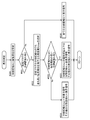
続いて、図4~図5を用いて、本実施形態における表示異常の判定処理を説明する。図4に示すように、まず、カウント数i=0に設定(#41)すると共に、信号処理部12にアクセスする(#42)。垂直同期信号が検出されない場合(#43No判定)、再度、信号処理部12にアクセスする(#42)。
一方、垂直同期信号が検出された場合(#43Yes判定)、垂直同期信号を抽出してパルス間隔時間Tを計測すると共に、水平同期信号を抽出する(#44)。次いで、パルス間隔時間Tを予め設定された分割領域数Nで除算し、分割同期時間(T/N)を算出する(#45)。次いで、カウント数i=1にインクリメント(#46)して、分割領域A1における水平同期信号のパルスを検出する(#47)。
次いで、垂直同期信号が検出されてから所定時間としての分割同期時間(T/N)が経過していない場合(#48No判定)、再度、分割領域A1における水平同期信号のパルスを検出する(#47)。一方、垂直同期信号が検出されてから所定時間(T/N)が経過した場合(#48Yes判定)、検出された分割領域A1における水平同期信号のパルス総個数であるパルス数P1が所定値(P1=195)以上か否かを判定する(#49)。
分割領域A1における水平同期信号のパルス数P1が所定値以上である場合(#49Yes判定)、分割領域A1に肯定フラグを立て(#50)、パルス数P1が所定値より小さい場合(#49Nо判定)、分割領域A1に否定フラグを立てる(#51)。次いで、カウント数iが分割領域数Nに達していない場合(#52No判定)、経過時間をリセットし(#54)、カウント数i=i+1にインクリメントし(#46)、分割領域Aiについて#47~#52を繰り返す。一方、カウント数iが分割領域数Nに達している場合(#52Yes判定)、表示判定を行い(#53)、判定結果を画像処理部2に出力する(#55)。
ここで、表示判定(#53)のサブルーチンについて、図5を用いて説明する。肯定フラグ又は否定フラグが立てられた分割領域Aiに、優先順位を設定する(#530)。次いで、否定フラグが立てられた分割領域Aiがない場合(#531Nо判定)、撮影画像PIが正常であるので、判定結果は、全ての分割領域Aiを表示する表示信号となる(#536)。
一方、否定フラグが立てられた分割領域Aiがある場合(#531Yes判定)、否定フラグが立てられた分割領域Aiのうち、最も高い優先順位を有する分割領域Aimaxを選択する(#532)。このとき、複数の分割領域Aiの優先順位が等しい場合、複数の分割領域Aiが最も高い優先順位を有する分割領域Aimaxとして選択される。そして、最も高い優先順位を有する分割領域Aimaxよりも優先順位の低い分割領域Aiがない場合(#533No判定)、判定結果は、最も高い優先順位を有する分割領域Aimaxのみが非表示信号となり、その他の分割領域Aiが表示信号となる(#534)。逆に、最も高い優先順位を有する分割領域Aimaxよりも優先順位の低い分割領域Aiがある場合(#533Yes判定)、最も高い優先順位を有する分割領域Aimaxの優先順位以下の分割領域Aiが非表示信号となり、その他の分割領域Aiが表示信号となる(#535)。上述した表示異常の判定処理は、垂直同期信号が検出される度にリアルタイムに実行されるので、各ステップはパルス間隔時間Tごとに反復されることとなる。
なお、表示異常の判定処理における各ステップは、本発明の要旨を逸脱しない範囲内で適宜順番を入れ替えても良い。また、表示判定サブルーチン(#53)の判定結果を、車載カメラ1の故障判定に用いても良く、必ずしも表示画面VIに車載カメラ1の撮影画像PIを表示する用途に限定されない。
[その他の実施形態]
(1)分割領域Aiの数は、1つのフレームFに設定される水平同期信号の総パルス数の範囲内で、更に細かく分割しても良く、特に限定されない。分割領域Aiの数が増えるほど、表示画面VIの表示領域および非表示領域が細分化され、運転状況に応じたきめ細かいモニター表示を実現することができる。また、判定部7は、分割領域Aiごとの水平同期信号のパルス数Piが、所定値(上述した実施形態では、分割領域Aiに本来存在すべき水平同期信号として200本)と等しい肯定条件を満足するか否かを判定しても良い。
この場合、より精度の高い判定を行うことができる。
(2)分割領域Aiは等間隔でなくても良く、例えば、優先度が高いほど分割領域Aiの面積を増大させても良い。この場合、優先順位の高い分割領域Aiの表示エリアが拡大されるので、更に見やすい表示画面VIとすることができる。
(3)上述した実施形態では、表示異常の判定処理を垂直同期信号が検出される度にリアルタイムに実行するとして説明したが、所定間隔おきに実行しても良い。この場合、先頭の判定結果が次の判定処理が開始されるまで適用されることとなる。
(4)時間計測部61は、車載カメラ1に予め定められた垂直同期信号のパルス間隔時間Tから計測しても良い。この場合、垂直同期信号が検出されれば、次の垂直同期信号が検出されるまで待機する必要がないので、車載カメラ1が撮影した撮影画像PIを表示画面VIとして表示するまでの時間を短縮することが可能となる。
(5)表示異常の判定処理における判定結果を蓄積する記憶部を別に設けても良い。この場合、表示異常の発生回数をカウントして、発生回数が所定回数以上であれば車載カメラ1の故障であるとしてドライバーに報知しても良い。
(1)分割領域Aiの数は、1つのフレームFに設定される水平同期信号の総パルス数の範囲内で、更に細かく分割しても良く、特に限定されない。分割領域Aiの数が増えるほど、表示画面VIの表示領域および非表示領域が細分化され、運転状況に応じたきめ細かいモニター表示を実現することができる。また、判定部7は、分割領域Aiごとの水平同期信号のパルス数Piが、所定値(上述した実施形態では、分割領域Aiに本来存在すべき水平同期信号として200本)と等しい肯定条件を満足するか否かを判定しても良い。
この場合、より精度の高い判定を行うことができる。
(2)分割領域Aiは等間隔でなくても良く、例えば、優先度が高いほど分割領域Aiの面積を増大させても良い。この場合、優先順位の高い分割領域Aiの表示エリアが拡大されるので、更に見やすい表示画面VIとすることができる。
(3)上述した実施形態では、表示異常の判定処理を垂直同期信号が検出される度にリアルタイムに実行するとして説明したが、所定間隔おきに実行しても良い。この場合、先頭の判定結果が次の判定処理が開始されるまで適用されることとなる。
(4)時間計測部61は、車載カメラ1に予め定められた垂直同期信号のパルス間隔時間Tから計測しても良い。この場合、垂直同期信号が検出されれば、次の垂直同期信号が検出されるまで待機する必要がないので、車載カメラ1が撮影した撮影画像PIを表示画面VIとして表示するまでの時間を短縮することが可能となる。
(5)表示異常の判定処理における判定結果を蓄積する記憶部を別に設けても良い。この場合、表示異常の発生回数をカウントして、発生回数が所定回数以上であれば車載カメラ1の故障であるとしてドライバーに報知しても良い。
本発明は、車載カメラで撮影した撮影画像を車両のモニター画面などに表示するときの表示異常を判定する撮影画像判定装置に利用可能である。
1 車載カメラ(カメラ)
4 同期信号抽出部
5 優先順位設定部
7 判定部
61 時間計測部
62 分割領域設定部
63 パルス数計測部
Ai 分割領域
F フレーム
K 仮想線
PI 撮影画像
Pi パルス数
T パルス間隔時間
X 撮影画像判定装置
4 同期信号抽出部
5 優先順位設定部
7 判定部
61 時間計測部
62 分割領域設定部
63 パルス数計測部
Ai 分割領域
F フレーム
K 仮想線
PI 撮影画像
Pi パルス数
T パルス間隔時間
X 撮影画像判定装置
Claims (4)
- カメラで撮影した撮影画像を表示するために用いられる垂直同期信号および水平同期信号を抽出する同期信号抽出部と、
前記垂直同期信号におけるパルス間隔時間を計測する時間計測部と、
前記パルス間隔時間に応じて表示される前記撮影画像のフレームを水平方向の仮想線で分割し、当該仮想線で区画された複数の分割領域を設定する分割領域設定部と、
夫々の前記分割領域に対応する前記水平同期信号のパルス数を計測するパルス数計測部と、
前記パルス数計測部で計測された前記パルス数が所定値以上となる肯定条件を満足するか否かを判定する判定部と、を備えている撮影画像判定装置。 - 複数の前記分割領域を表示させる優先順位を設定する優先順位設定部を備え、
前記判定部は、前記肯定条件を満足しないと判定した前記分割領域の前記優先順位以下に設定された前記分割領域に対応する前記撮影画像を表示させない非表示信号を出力する請求項1に記載の撮影画像判定装置。 - 前記優先順位設定部は、前記撮影画像の下方にある前記分割領域ほど前記優先順位を高く設定する請求項2に記載の撮影画像判定装置。
- 前記判定部は、前記肯定条件を満足しないと判定した前記分割領域に対応する前記撮影画像をマスキング処理するマスキング信号を出力する請求項1~3のいずれか一項に記載の撮影画像判定装置。
Priority Applications (1)
| Application Number | Priority Date | Filing Date | Title |
|---|---|---|---|
| US16/309,129 US10742851B2 (en) | 2016-06-13 | 2017-03-24 | Captured image decision device |
Applications Claiming Priority (2)
| Application Number | Priority Date | Filing Date | Title |
|---|---|---|---|
| JP2016-116882 | 2016-06-13 | ||
| JP2016116882A JP2017224876A (ja) | 2016-06-13 | 2016-06-13 | 撮影画像判定装置 |
Publications (1)
| Publication Number | Publication Date |
|---|---|
| WO2017217062A1 true WO2017217062A1 (ja) | 2017-12-21 |
Family
ID=60663205
Family Applications (1)
| Application Number | Title | Priority Date | Filing Date |
|---|---|---|---|
| PCT/JP2017/011926 Ceased WO2017217062A1 (ja) | 2016-06-13 | 2017-03-24 | 撮影画像判定装置 |
Country Status (3)
| Country | Link |
|---|---|
| US (1) | US10742851B2 (ja) |
| JP (1) | JP2017224876A (ja) |
| WO (1) | WO2017217062A1 (ja) |
Families Citing this family (7)
| Publication number | Priority date | Publication date | Assignee | Title |
|---|---|---|---|---|
| US10816354B2 (en) | 2017-08-22 | 2020-10-27 | Tusimple, Inc. | Verification module system and method for motion-based lane detection with multiple sensors |
| US11009356B2 (en) | 2018-02-14 | 2021-05-18 | Tusimple, Inc. | Lane marking localization and fusion |
| US11009365B2 (en) * | 2018-02-14 | 2021-05-18 | Tusimple, Inc. | Lane marking localization |
| US12270661B2 (en) | 2018-02-14 | 2025-04-08 | Tusimple, Inc. | Lane marking localization and fusion |
| EP3893150A1 (en) | 2020-04-09 | 2021-10-13 | Tusimple, Inc. | Camera pose estimation techniques |
| CN112004080B (zh) * | 2020-08-28 | 2021-06-11 | 安徽江淮汽车集团股份有限公司 | 汽车显示设备的故障检测方法、设备、存储介质及装置 |
| KR20230161708A (ko) | 2022-05-19 | 2023-11-28 | 현대자동차주식회사 | 차량 및 그 제어 방법 |
Citations (5)
| Publication number | Priority date | Publication date | Assignee | Title |
|---|---|---|---|---|
| JP2001134244A (ja) * | 1999-11-09 | 2001-05-18 | Toshiba Corp | 平面表示装置及びその駆動方法 |
| JP2006229341A (ja) * | 2005-02-15 | 2006-08-31 | Sanyo Electric Co Ltd | 撮像装置 |
| JP2007318558A (ja) * | 2006-05-26 | 2007-12-06 | Fujitsu Ten Ltd | 画像処理装置 |
| JP2010176030A (ja) * | 2009-01-30 | 2010-08-12 | Fujitsu Ten Ltd | 表示装置および表示制御装置 |
| JP2014187496A (ja) * | 2013-03-22 | 2014-10-02 | Denso Corp | 故障検出装置 |
Family Cites Families (3)
| Publication number | Priority date | Publication date | Assignee | Title |
|---|---|---|---|---|
| JPH08317313A (ja) | 1995-05-19 | 1996-11-29 | Fujitsu General Ltd | ディスプレイ装置 |
| JP2007096633A (ja) * | 2005-09-28 | 2007-04-12 | Matsushita Electric Ind Co Ltd | 映像信号処理装置およびデジタルカメラ |
| JP2009044572A (ja) | 2007-08-10 | 2009-02-26 | Fujitsu Ten Ltd | 異常検知装置、画像表示装置及び異常検知方法 |
-
2016
- 2016-06-13 JP JP2016116882A patent/JP2017224876A/ja active Pending
-
2017
- 2017-03-24 US US16/309,129 patent/US10742851B2/en not_active Expired - Fee Related
- 2017-03-24 WO PCT/JP2017/011926 patent/WO2017217062A1/ja not_active Ceased
Patent Citations (5)
| Publication number | Priority date | Publication date | Assignee | Title |
|---|---|---|---|---|
| JP2001134244A (ja) * | 1999-11-09 | 2001-05-18 | Toshiba Corp | 平面表示装置及びその駆動方法 |
| JP2006229341A (ja) * | 2005-02-15 | 2006-08-31 | Sanyo Electric Co Ltd | 撮像装置 |
| JP2007318558A (ja) * | 2006-05-26 | 2007-12-06 | Fujitsu Ten Ltd | 画像処理装置 |
| JP2010176030A (ja) * | 2009-01-30 | 2010-08-12 | Fujitsu Ten Ltd | 表示装置および表示制御装置 |
| JP2014187496A (ja) * | 2013-03-22 | 2014-10-02 | Denso Corp | 故障検出装置 |
Also Published As
| Publication number | Publication date |
|---|---|
| US10742851B2 (en) | 2020-08-11 |
| JP2017224876A (ja) | 2017-12-21 |
| US20190312993A1 (en) | 2019-10-10 |
Similar Documents
| Publication | Publication Date | Title |
|---|---|---|
| JP2017224876A (ja) | 撮影画像判定装置 | |
| TWI600558B (zh) | Dynamic lane detection system and method | |
| US8854466B2 (en) | Rearward view assistance apparatus displaying cropped vehicle rearward image | |
| US9669761B2 (en) | Around view monitoring apparatus and method thereof | |
| US9001204B2 (en) | Vehicle peripheral monitoring device | |
| JP2010033106A (ja) | 運転者支援装置、運転者支援方法および運転者支援処理プログラム | |
| US20190122387A1 (en) | Apparatus and method for image processing according to vehicle speed | |
| JPWO2018042976A1 (ja) | 画像生成装置、画像生成方法、記録媒体、および画像表示システム | |
| US20220417427A1 (en) | Image processing apparatus that retouches and displays picked-up image, image processing method, and storage medium | |
| JP5519413B2 (ja) | 瞳孔隠蔽状態検出装置及びそれを備えた車載カメラ | |
| JP5240517B2 (ja) | 車載カメラの校正装置 | |
| JP2007235532A (ja) | 車両用監視装置 | |
| EP3200445B1 (en) | Image capture device, vehicle, and fluctuation detecting method | |
| KR102632361B1 (ko) | 어라운드 뷰 영상 제공 시스템 | |
| JP2012147308A (ja) | 画像処理装置、画像表示システム、及び、画像処理方法 | |
| JP6754993B2 (ja) | 車載映像表示装置、車載映像表示方法、およびプログラム | |
| KR20130029962A (ko) | 차량용 영상 표시 장치 및 차량용 카메라로부터 입력된 급격한 영상 변화 표시 방법 | |
| US12537911B2 (en) | Video processing apparatus | |
| EP4258653A1 (en) | Image processing device that can measure distance to object, movable apparatus, image processing method, and storage medium | |
| KR20150025391A (ko) | 충격방향을 감지하고 표시하는 장치 및 방법 | |
| CN101253763A (zh) | 摄像装置 | |
| JP5940248B2 (ja) | 車両の画像処理システム | |
| KR20160030680A (ko) | 차량내 영상 시스템 및 영상처리 방법 | |
| JP2007323495A (ja) | 画像合成装置 | |
| JP2016225904A (ja) | 画像信号処理装置 |
Legal Events
| Date | Code | Title | Description |
|---|---|---|---|
| 121 | Ep: the epo has been informed by wipo that ep was designated in this application |
Ref document number: 17812968 Country of ref document: EP Kind code of ref document: A1 |
|
| NENP | Non-entry into the national phase |
Ref country code: DE |
|
| 122 | Ep: pct application non-entry in european phase |
Ref document number: 17812968 Country of ref document: EP Kind code of ref document: A1 |