WO2017213095A1 - 車両の排気バルブ装置 - Google Patents
車両の排気バルブ装置 Download PDFInfo
- Publication number
- WO2017213095A1 WO2017213095A1 PCT/JP2017/020859 JP2017020859W WO2017213095A1 WO 2017213095 A1 WO2017213095 A1 WO 2017213095A1 JP 2017020859 W JP2017020859 W JP 2017020859W WO 2017213095 A1 WO2017213095 A1 WO 2017213095A1
- Authority
- WO
- WIPO (PCT)
- Prior art keywords
- joint member
- exhaust valve
- slits
- valve device
- exhaust
- Prior art date
- Legal status (The legal status is an assumption and is not a legal conclusion. Google has not performed a legal analysis and makes no representation as to the accuracy of the status listed.)
- Ceased
Links
Images




Classifications
-
- F—MECHANICAL ENGINEERING; LIGHTING; HEATING; WEAPONS; BLASTING
- F01—MACHINES OR ENGINES IN GENERAL; ENGINE PLANTS IN GENERAL; STEAM ENGINES
- F01N—GAS-FLOW SILENCERS OR EXHAUST APPARATUS FOR MACHINES OR ENGINES IN GENERAL; GAS-FLOW SILENCERS OR EXHAUST APPARATUS FOR INTERNAL-COMBUSTION ENGINES
- F01N13/00—Exhaust or silencing apparatus characterised by constructional features
- F01N13/08—Other arrangements or adaptations of exhaust conduits
-
- F—MECHANICAL ENGINEERING; LIGHTING; HEATING; WEAPONS; BLASTING
- F02—COMBUSTION ENGINES; HOT-GAS OR COMBUSTION-PRODUCT ENGINE PLANTS
- F02D—CONTROLLING COMBUSTION ENGINES
- F02D9/00—Controlling engines by throttling air or fuel-and-air induction conduits or exhaust conduits
- F02D9/04—Controlling engines by throttling air or fuel-and-air induction conduits or exhaust conduits concerning exhaust conduits
-
- F—MECHANICAL ENGINEERING; LIGHTING; HEATING; WEAPONS; BLASTING
- F02—COMBUSTION ENGINES; HOT-GAS OR COMBUSTION-PRODUCT ENGINE PLANTS
- F02D—CONTROLLING COMBUSTION ENGINES
- F02D9/00—Controlling engines by throttling air or fuel-and-air induction conduits or exhaust conduits
- F02D9/08—Throttle valves specially adapted therefor; Arrangements of such valves in conduits
- F02D9/10—Throttle valves specially adapted therefor; Arrangements of such valves in conduits having pivotally-mounted flaps
-
- F—MECHANICAL ENGINEERING; LIGHTING; HEATING; WEAPONS; BLASTING
- F16—ENGINEERING ELEMENTS AND UNITS; GENERAL MEASURES FOR PRODUCING AND MAINTAINING EFFECTIVE FUNCTIONING OF MACHINES OR INSTALLATIONS; THERMAL INSULATION IN GENERAL
- F16D—COUPLINGS FOR TRANSMITTING ROTATION; CLUTCHES; BRAKES
- F16D3/00—Yielding couplings, i.e. with means permitting movement between the connected parts during the drive
- F16D3/50—Yielding couplings, i.e. with means permitting movement between the connected parts during the drive with the coupling parts connected by one or more intermediate members
-
- F—MECHANICAL ENGINEERING; LIGHTING; HEATING; WEAPONS; BLASTING
- F16—ENGINEERING ELEMENTS AND UNITS; GENERAL MEASURES FOR PRODUCING AND MAINTAINING EFFECTIVE FUNCTIONING OF MACHINES OR INSTALLATIONS; THERMAL INSULATION IN GENERAL
- F16K—VALVES; TAPS; COCKS; ACTUATING-FLOATS; DEVICES FOR VENTING OR AERATING
- F16K1/00—Lift valves or globe valves, i.e. cut-off apparatus with closure members having at least a component of their opening and closing motion perpendicular to the closing faces
- F16K1/32—Details
-
- F—MECHANICAL ENGINEERING; LIGHTING; HEATING; WEAPONS; BLASTING
- F16—ENGINEERING ELEMENTS AND UNITS; GENERAL MEASURES FOR PRODUCING AND MAINTAINING EFFECTIVE FUNCTIONING OF MACHINES OR INSTALLATIONS; THERMAL INSULATION IN GENERAL
- F16K—VALVES; TAPS; COCKS; ACTUATING-FLOATS; DEVICES FOR VENTING OR AERATING
- F16K49/00—Means in or on valves for heating or cooling
Definitions
- the present invention relates to an exhaust valve device for a vehicle, and more particularly, to an exhaust valve structure provided in an exhaust passage of the vehicle.
- An exhaust valve may be provided in the exhaust passage of a four-wheeled vehicle or a two-wheeled vehicle, and is used for various applications such as reduction of exhaust noise, switching of exhaust sound quality, or early warm-up of an engine using exhaust heat. It's being used.
- the exhaust valve provided in the exhaust passage is driven to the closed side to restrict the flow of the exhaust gas.
- the exhaust pressure usually guided to the silencer is guided to bypass the silencer by opening and closing the exhaust valve to increase the sound pressure.
- exhaust gas is guided to the engine side by opening and closing the exhaust valve, and the temperature of the engine is raised by the heat.
- the joint member is manufactured by bending a wire made of spring steel into a C shape.
- an actuator is disposed in the vicinity of the exhaust valve via the joint member. Are connected. And since the motor built in the actuator, the plastic gear, etc. are weak to heat, the joint member is required to have high heat insulation.
- Patent Document 1 has a problem that a large amount of heat is transmitted to the actuator through the joint member, causing troubles such as failure.
- the present invention has been made to solve such problems, and an object of the present invention is to provide a vehicle exhaust valve device that can achieve high heat insulation and protect an actuator. .
- an exhaust valve device for a vehicle supports an exhaust valve that can be opened and closed by a rotating shaft in an exhaust passage, and an actuator for driving the exhaust valve is disposed in the vicinity of the exhaust passage.
- an exhaust valve device for a vehicle in which the output shaft of the actuator is opposed to the rotation shaft so that the axis is coincident with the rotation shaft, and the output shaft and the rotation shaft are connected via a joint member.
- the plate-like conductive portions are connected to each other and have a shape that is continuous in the axial direction.
- the joint member has rigidity capable of transmitting the rotation of the output shaft of the actuator to the rotation shaft of the exhaust valve while suppressing elastic deformation.
- the connection parts adjacent via the plate-like conductive part are arranged without overlapping each other when viewed from the axial direction.
- the slits are alternately formed from two directions in which a phase of approximately 180 ° is opposed to the axis of the joint member.
- the joint member is manufactured by a metal injection method.
- the joint member is preferably manufactured by a lost wax method.
- the exhaust valve device for a vehicle of the present invention since the plate-like conductive portions are connected to each other via the connecting portions and are connected in the axial direction, the heat from the exhaust valve follows the zigzag path and conducts heat. As a result, the heat conduction path is extended. At the same time, the heat conduction area is limited to be equivalent to the cross-sectional areas of the plate-like conduction part and the connecting part and is reduced, so that the heat insulating property of the joint member becomes high. Moreover, much heat is taken away by the traveling wind due to the increase in the surface area of the joint member. Due to these factors, the amount of heat transmitted to the actuator via the joint member can be reduced, and the actuator can be protected.
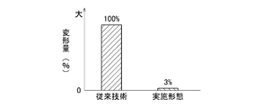
- FIG. 3 is a sectional view taken along the line III-III in FIG. It is the test result which compared the deformation amount of the twist direction of the joint member at the time of rotation transmission with the prior art. It is a test result which compared with the prior art the amount of heat transmitted to an actuator via a joint member.
- FIG. 7 is a sectional view taken along the line VII-VII in FIG. 6 showing the joint member. It is a front view which shows the joint member of 3rd Embodiment. It is a longitudinal cross-sectional view which similarly shows a joint member.
- FIG. 9 is a sectional view taken along the line XX of FIG. 8 showing the joint member.
- FIG. 1 is a cross-sectional view of an exhaust passage of a four-wheeled vehicle to which an exhaust valve device 1 of the present embodiment is applied as viewed from the rear.
- the description regarding the upper and lower sides of the following description is a direction on drawing to the last, and is not structural limitation.
- the exhaust passage 2 extends in the front-rear direction under the floor of the vehicle. Although not shown, its front end is connected to an engine exhaust manifold, and its rear end is connected to a silencer.
- the exhaust passage 2 is in the form of a pipe having a cylindrical cross section, and its upper half is shown in FIG.
- a rotation shaft 3 is disposed in the exhaust passage 2 so as to penetrate in the vertical direction, and both upper and lower ends of the rotation shaft 3 are rotatably supported by a bearing 4 (only the upper side is shown).
- a disk-shaped butterfly exhaust valve 5 is fixed to the rotation shaft 3 in the exhaust passage 2 and can rotate about the axis L (also an axis of a joint member 9 described later) together with the rotation shaft 3. .
- the exhaust valve 5 of the present embodiment is intended to reduce exhaust noise, and is normally switched to an open position along the exhaust circulation direction shown in the drawing to allow the exhaust gas to flow. Then, for example, in a high engine speed range, the exhaust valve 5 is switched to a closed position where the exhaust valve 5 is closed to a predetermined opening, thereby restricting the flow of exhaust gas and reducing exhaust noise.
- the function of the exhaust valve 5 of the present invention is not limited to this, and can be applied to various uses.
- a pair of leg portions 6a of a bracket 6 formed by bending a steel plate is welded on the exhaust passage 2, and a base plate 7 is welded on a main body surface 6b connecting the upper portions of both leg portions 6a.
- An actuator 8 for opening and closing the exhaust valve 5 is fixed on the base plate 7 with a screw (not shown), and the output shaft 8a of the actuator 8 is in a position coinciding with the axis L, and the base plate 7 and the body surface 6b of the bracket 6 are connected. And protrudes downward.
- the output shaft 8a opposes the rotational shaft 3 of the exhaust valve 5 protruding upward from the exhaust passage 2 with a predetermined interval, and between the output shaft 8a and the rotational shaft 3.
- the joint member 9 is disposed so as to be positioned on the axis L.
- the output shaft 8a of the actuator 8 and the rotating shaft 3 of the exhaust valve 5 are connected by the joint member 9. That is, a plate-like engagement piece 10 projects from the upper portion of the joint member 9, an engagement groove 11 is formed at the tip of the output shaft 8 a of the actuator 8, and the engagement piece 10 is placed in the engagement groove 11. The rotation of the output shaft 8a is transmitted to the joint member 9 by being fitted.
- an engagement hole 12 having a square section is formed in the lower portion of the joint member 9, and an engagement piece 13 having a square section is formed on the upper end of the rotation shaft 3 of the exhaust valve 5. Is inserted into the engagement hole 12 so that the rotation of the joint member 9 is transmitted to the rotation shaft 3.
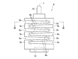
- FIG. 2 is a front view showing the joint member 9 of the first embodiment
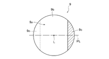
- FIG. 3 is a sectional view taken along the line III-III of FIG.
- the joint member 9 has a cylindrical shape extending in the vertical direction along the axis L.
- the engaging piece 10 protrudes from the upper part and the engaging hole 12 is recessed from the lower part.
- slits 9 a are alternately formed from two directions whose phases are opposed to the axis L by 180 °, and the slits 9 a are arranged in parallel in the direction of the axis L.
- a plate-like conductive portion 9b is formed between the slits 9a adjacent to each other in the axis L direction, and the depth of each slit 9a is shallower than the diameter of the joint member 9 in the direction orthogonal to the axis L.
- the connecting part 9c is left in the collar part.
- the plate-like conductive portions 9b are divided in the direction of the axis L by the respective slits 9a and are connected to each other via the respective connecting portions 9c, and such a plurality of plate-like conductive portions 9b are connected in the direction of the axis L.
- the joint member 9 is configured by being connected.
- the slit 9a is formed in a tapered cross section so that the width becomes narrower toward the extreme side of the slit 9a, but the cross-sectional shape of the slit 9a is not limited to this.
- the slit 9a is formed from a direction orthogonal to the axis L, but it is not necessary to be a complete orthogonal direction, and the formation direction of the slit 9a may be other than the orthogonal direction.
- the shape, arrangement, and the like of the slit 9a are set so that sufficient rigidity is secured to the joint member 9 even after the formation of each slit 9a. More specifically, since the elastic deformation in the torsional direction around the axis L of the joint member 9 at the time of rotation transmission is caused by the bending of the plate-like conductive portion 9b and the connecting portion 9c, the slit 9a is formed. Therefore, the shape and arrangement of the slits 9a are set so that the thickness of the plate-like conductive portion 9b and the connecting portion 9c is not reduced more than necessary. However, as described below, an excessive thickness of the plate-like conductive portion 9b and the connecting portion 9c causes a decrease in heat insulation due to an increase in the heat transfer area, and thus is set in consideration of the balance between the two.
- the material of the joint member 9 is a metal material such as stainless steel (SUS) or heat resistant steel (SUH) that is excellent in heat resistance and corrosion resistance in consideration of use in a high temperature environment, specifically, SUS303, SUS304. SUS316, SUS410, SUS420, SUS430, SUS431, SUS630, etc. are used.
- a metal injection method (metal powder injection molding method) is applied. Since the manufacturing method is a well-known technique, only a brief description will be given, but after mixing the raw metal powder and a binder (binder), the mixture is injection-molded into a mold, and then the molded product is degreased in a vacuum furnace and heated to a high temperature. It is a manufacturing method that is completed by sintering. Application of this metal injection method makes it possible to manufacture the joint member 9 easily and inexpensively, for example, as compared with production by cutting. Note that precision casting by the lost wax method may be applied instead of the metal injection method, and even in this case, the joint member 9 can be manufactured easily and inexpensively.
- the metal injection method is a kind of injection molding, a product shape that can be molded with a small number of molds is desirable, and the shape of the joint member 9 described above is a result of taking this point into consideration as well as ensuring rigidity. That is, the joint member 9 can be formed by a pair of molds by setting a mold parting line PL along the formation direction of the slits 9a as shown in FIG.
- the exhaust valve 5 can accurately rotate the output shaft 8a of the actuator 8 while suppressing elastic deformation in the torsional direction about the axis L. Can be transmitted to the rotary shaft 3. Therefore, the exhaust valve 5 can always be driven to open and close in accordance with the control amount of the actuator 8, thereby realizing high controllability.
- the heat transmitted to the joint member 9 from the exhaust valve 5 heated by the exhaust gas flows from the lowermost plate-like conductive portion 9b of the joint member 9 to the plate-like conductive portion directly above via the connecting portion 9c continuous therewith. 9b, and further transmitted from the plate-like conductive portion 9b to the plate-like conductive portion 9b immediately above through the connecting portion 9c continuous therewith. After repeating the above, it is transmitted to the output shaft 8a of the actuator 8.
- the heat from the exhaust valve 5 is zigzag in the order of the plate-like conductive portion 9b, the connecting portion 9c, the plate-like conductive portion 9b, and the connecting portion 9c from the lower part of the joint member 9, as shown by the arrows in FIG. Since the heat conduction follows the path, the heat conduction path is greatly extended, and the heat conduction area is limited to the cross-sectional area of the plate-like conduction part 9b and the connecting part 9c to be greatly reduced. Due to these factors, the heat insulating property of the joint member 9 becomes very high, and the amount of heat transmitted to the actuator 8 through the joint member 9 can be reduced to protect the actuator 8, thereby preventing troubles such as failure. can do.
- the adjacent connecting portions 9c via the plate-like conductive portions 9b are located at the most spaced positions (joint members without overlapping each other when viewed from the axis L direction). 9 on the opposite side of the diameter direction). For this reason, a long plate-like conductive portion 9b substantially corresponding to the diameter of the joint member 9 is formed, and the heat conduction path can be extended most with the same number of slits, so that the heat insulation is very excellent.
- the surface area of the joint member 9 is greatly increased by the formation of the slit 9a.
- the joint member 9 is always exposed to the traveling wind and cooled, and the cooling action increases as the contact area with the traveling wind increases. For this reason, in this embodiment, most of the heat transmitted through the inside of the joint member 9 is taken away by the traveling wind, and the amount of heat transmitted to the actuator 8 is further reduced by that amount. This factor also contributes to trouble.
- FIG. 4 shows test results comparing the amount of deformation of the joint member 9 in the torsional direction during rotation transmission with that of the prior art (Patent Document 1).
- Patent Document 1 shows test results comparing the amount of deformation of the joint member 9 in the torsional direction during rotation transmission with that of the prior art (Patent Document 1).
- the amount of deformation in the torsional direction is reduced to 3% compared to that of the prior art, and from this test result, the controllability is improved. I can prove it.
- FIG. 5 is a test result in which the amount of heat transmitted to the actuator 8 through the joint member 9 is compared with the prior art (Patent Document 1). As shown in this figure, according to the joint member 9 of the present embodiment, the amount of heat transfer is further reduced as compared with that of the prior art, and the improvement in heat insulation can be proved from this test result.
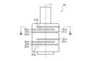
- FIG. 6 is a front view showing the joint member of the second embodiment
- FIG. 7 is a sectional view taken along the line VII-VII of FIG. 6 showing the joint member.
- the joint member 21 of the present embodiment is also provided with a connection structure for connecting the upper part to the output shaft 8a of the actuator 8 and the lower part to the rotating shaft 3 of the exhaust valve 5.
- the connection structure may be the same connection structure as in the first embodiment, or another connection structure. This also applies to a third embodiment described later.
- slits 21a are alternately formed from three directions whose phases are shifted by 90 ° with respect to the axis L, and the slits 21a are arranged in parallel in the direction of the axis L.
- a region between adjacent slits 21a is a plate-like conductive portion 21b, and a region left at the most end of each slit 21a is a connecting portion 21c, and each plate-like conduction is made via each connecting portion 21c.
- the part 21b is connected and continues in the axis L direction.
- the metal exemplified in the first embodiment is appropriately selected, and the manufacturing method is manufactured by cutting each slit with a metal saw, for example, similarly to the coupling of Patent Document 2. ing.
- the metal injection method of the first embodiment may be applied. This also applies to a third embodiment described later.
- the shape and arrangement of the slits 21a are set so that the joint member 21 has sufficient rigidity. Therefore, although not redundantly described, the controllability is improved by accurately transmitting the rotation of the output shaft 8a of the actuator 8 to the rotating shaft 3 of the exhaust valve 5 while suppressing elastic deformation in the torsional direction. Can do.
- the connecting portions 21c adjacent in the direction of the axis L only have a few regions overlapping each other, and most of the regions do not overlap. Therefore, as in the first embodiment, heat from the exhaust valve 5 follows the zigzag path from the lower part of the joint member 21 in the order of the plate-like conductive portion 21b, the connecting portion 21c, the plate-like conductive portion 21b, and the connecting portion 21c.
- the heat conduction path is lengthened by conduction, and the heat conduction area is limited to be equivalent to the cross-sectional areas of the plate-like conduction part 21b and the coupling part 21c, thereby reducing heat insulation.
- the surface area of the joint member 21 is increased due to the formation of the slits 21a, cooling by running wind can be expected. As a result, the amount of heat transmitted to the actuator 8 via the joint member 21 can be reduced, and troubles such as failure can be prevented.
- FIG. 8 is a front view showing the joint member of the third embodiment
- FIG. 9 is a longitudinal sectional view showing the joint member
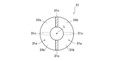
- FIG. 10 is a sectional view taken along the line XX of FIG.
- the joint member 31 has a cylindrical shape, and a through hole 31d is formed along the axis L at the center thereof.
- a pair of slits 31a are formed from two directions with a phase opposite to the axis L at a position coincident with the axis L, and each of the slits 31a is set as one set.
- a pair of slits 31 a are arranged in parallel in the direction of the axis L while shifting the phase by 90 ° alternately with respect to the axis L.
- a region between adjacent sets of slits 31a is a plate-like conductive portion 31b, and a pair of regions remaining between the sets of slits 31a is a connecting portion 31c, and each connecting portion 31c is interposed via each connecting portion 31c.
- Each plate-like conduction part 31b is connected and continues in the direction of the axis L.
- the shape and arrangement of the slit 31a and the inner diameter of the through hole 31d are set so that sufficient rigidity is ensured in the joint member 31, so that elastic deformation in the twisting direction is suppressed.
- the rotation of the output shaft 8a of the actuator 8 can be accurately transmitted to the rotation shaft 3 of the exhaust valve 5, and the controllability can be improved.
- the connecting portions 31c adjacent in the direction of the axis L do not overlap, the heat from the exhaust valve 5 flows from the lower part of the joint member 31 to the plate-like conductive portion 31b, the pair of connecting portions 31c, and the plate-like shape.
- the conduction portion 31b and the pair of connecting portions 31c follow the zigzag path in this order to conduct heat, the heat conduction path becomes long, and the heat conduction area is limited to the cross-sectional area of the plate-like conduction portion 31b and the connecting portion 31c.
- the heat insulation is improved.
- the surface area of the joint member 31 is increased by the formation of the slit 31a, cooling by traveling wind can be expected. As a result, the amount of heat transmitted to the actuator 8 via the joint member 31 can be reduced, and troubles such as failure can be prevented.
- the aspect of the present invention is not limited to this embodiment.
- the exhaust valve device for a four-wheel vehicle is embodied, but the present invention may be applied to a two-wheel vehicle or a three-wheel vehicle instead.
- the materials, shapes, and the like of the joint members 9, 21, and 31 are not limited to the above embodiment, and can be arbitrarily changed.
Landscapes
- Engineering & Computer Science (AREA)
- General Engineering & Computer Science (AREA)
- Mechanical Engineering (AREA)
- Chemical & Material Sciences (AREA)
- Combustion & Propulsion (AREA)
- Exhaust Silencers (AREA)
Abstract
排気通路(2)内で排気バルブ(5)を回動軸(3)により開閉可能に支持し、排気通路の近傍に配設されたアクチュエータ(8)の出力軸(8a)を回動軸に相対向させて金属材料からなるジョイント部材(9)により連結する。ジョイント部材の外周面に軸線Lに対して180°位相を対向させた2方向から交互にスリット(9a)を形成し、各スリットの最奧部に残された連結部(9c)を介して各スリット間の板状伝導部(9b)が軸線方向に連なる形状とすることで、ジョイント部材内での熱伝導経路を延長化し且つ熱伝導面積を縮小する。また、ジョイント部材に十分な剛性が確保されるようにスリットの形状や配置等を設定し、回転伝達時のジョイント部材の捩り方向の弾性変形を抑制する。
Description
本発明は、車両の排気バルブ装置に係り、特に車両の排気通路に設けられた排気バルブの構造に関する。
4輪車両や2輪車両の排気通路には排気バルブが設けられる場合があり、排気騒音の低減や排気音質の切換、或いは排気熱を利用したエンジンの早期暖機等のような種々の用途に利用されている。例えば排気騒音を低減する場合には、排気通路に設けた排気バルブを閉側に駆動して排ガスの流通を制限する。また排気音質を切り換える場合には、通常は消音器に案内される排ガスを排気バルブの開閉により消音器を迂回するように導いて音圧を高める。またエンジンを早期暖機する場合には、排気バルブの開閉により排ガスをエンジン側に導いてその熱でエンジンを昇温する。
何れの用途においても、排気バルブをアクチュエータにより開閉駆動する必要があり、そのために、例えば特許文献1に記載のような排気バルブ装置が採用されている。当該特許文献1の技術では、排気通路内で排気バルブを開閉可能に支持すると共に、排気通路にブラケットを介してアクチュエータを固定支持し、アクチュエータの出力軸をジョイント部材を介して回動軸に連結している。
排気バルブ装置の組立の際に、アクチュエータの出力軸と排気バルブの回動軸との間に偏芯や偏角が生じる場合があることから、偏芯や偏角を吸収可能な可撓性を付与するために、ジョイント部材はバネ鋼からなる線材をC字状に湾曲形成して製作されている。
ところで、本発明の車両の排気バルブ装置では、高温(例えば800°程度)の排気通路内に配設された排気バルブを開閉するために、その近接位置にアクチュエータが配設されてジョイント部材を介して連結されている。そして、アクチュエータに内蔵されたモータやプラスチック製のギヤ等は熱に弱いことから、ジョイント部材には高い断熱性が要求される。
しかしながら、特許文献1に記載の排気バルブ装置では、ジョイント部材を介して多量の熱がアクチュエータに伝達され、故障等のトラブルを引き起こしてしまうという問題があった。
本発明はこのような問題点を解決するためになされたもので、その目的とするところは、高い断熱性を達成してアクチュエータを保護することができる車両の排気バルブ装置を提供することにある。
上記の目的を達成するため、本発明の車両の排気バルブ装置は、排気通路内で排気バルブを回動軸により開閉可能に支持し、排気バルブの駆動用のアクチュエータを排気通路の近傍に配設し、アクチュエータの出力軸を回動軸に対して軸線を一致させて相対向させると共に、出力軸と回動軸とをジョイント部材を介して連結した車両の排気バルブ装置であって、ジョイント部材が、金属材料からなり、その外側面に軸線に対して異なる位相で複数のスリットが軸線方向に並設されることにより、各スリットの最奧部に残された連結部を介して各スリット間の板状伝導部が互いに連結されて軸線方向に連なった形状を有することを特徴とする。
その他の態様として、ジョイント部材が、弾性変形を抑制しつつアクチュエータの出力軸の回転を排気バルブの回動軸に伝達可能な剛性を備えることが好ましい。
その他の態様として、板状伝導部を介して隣り合う連結部が、軸線方向から見て互いに重なることなく配置されることが好ましい。
その他の態様として、スリットが、ジョイント部材の軸線に対して略180°位相を対向させた2方向から交互に形成されることが好ましい。
その他の態様として、板状伝導部を介して隣り合う連結部が、軸線方向から見て互いに重なることなく配置されることが好ましい。
その他の態様として、スリットが、ジョイント部材の軸線に対して略180°位相を対向させた2方向から交互に形成されることが好ましい。
その他の態様として、ジョイント部材を、メタルインジェクション法により製作することが好ましい。
その他の態様として、ジョイント部材を、ロストワックス法により製作することが好ましい。
その他の態様として、ジョイント部材を、ロストワックス法により製作することが好ましい。
本発明の車両の排気バルブ装置によれば、各連結部を介して板状伝導部が互いに連結されて軸線方向に連なっているため、排気バルブからの熱がジグザグ状の経路を辿って熱伝導されて熱伝導経路が延長化される。これと共に熱伝導面積が板状伝導部や連結部の断面積相当に制限されて縮小されることから、ジョイント部材の断熱性が高いものとなる。また、ジョイント部材の表面積の増加により熱の多くが走行風に奪われる。これらの要因により、ジョイント部材を介してアクチュエータに伝達される熱量を減少可能となり、アクチュエータを保護することができる。
[第1実施形態]
以下、本発明を4輪車両の排気バルブ装置に具体化した第1実施形態を説明する。
図1は本実施形態の排気バルブ装置1が適用された4輪車両の排気通路を後方より見た断面図である。なお、以下の説明の上下に関する記載は、あくまで図面上の方向であり、構造的な限定ではない。
以下、本発明を4輪車両の排気バルブ装置に具体化した第1実施形態を説明する。
図1は本実施形態の排気バルブ装置1が適用された4輪車両の排気通路を後方より見た断面図である。なお、以下の説明の上下に関する記載は、あくまで図面上の方向であり、構造的な限定ではない。
排気通路2は車両の床下で前後方向に延設されており、図示はしないが、その前端はエンジンの排気マニホールドに連結され、後端は消音器に連結されている。排気通路2は円筒断面のパイプ状をなし、図1ではその上側約半分が示されている。排気通路2には上下方向に貫通するように回動軸3が配設され、回動軸3の上下両端は軸受け4(上側のみ示す)に回動可能に支持されている。
排気通路2内において回動軸3には円盤状をなすバタフライ式の排気バルブ5が固定され、回動軸3と共に軸線L(後述するジョイント部材9の軸線でもある)を中心として回動し得る。本実施形態の排気バルブ5は排気騒音の低減を目的としたものであり、通常時には図に示す排気流通方向に沿った開位置に切り換えられて排ガスの流通を許容している。そして、例えばエンジンの高回転域では排気バルブ5が所定開度まで閉じた閉位置に切り換えられ、排ガスの流通を制限して排気騒音を低減する。但し、本発明の排気バルブ5の機能はこれに限るものではなく、種々の用途に適用可能である。
排気通路2上には鋼板を折曲形成したブラケット6の一対の脚部6aが溶接され、両脚部6aの上部を連結する本体面6b上にはベース板7が溶接されている。ベース板7上には排気バルブ5を開閉駆動するためのアクチュエータ8が図示しないビスにより固定され、アクチュエータ8の出力軸8aは上記軸線Lと一致した位置でベース板7及びブラケット6の本体面6bを貫通して下方に突出している。結果として出力軸8aは、排気通路2から上方に突出した排気バルブ5の回動軸3に対して所定の間隔をおいて相対向し、これらの出力軸8aと回動軸3との間には軸線L上に位置するようにジョイント部材9が配設されている。
ジョイント部材9の構成については後述するが、このジョイント部材9によりアクチュエータ8の出力軸8aと排気バルブ5の回動軸3とが連結されている。即ち、ジョイント部材9の上部には板状の係合片10が突設され、アクチュエータ8の出力軸8aの先端には係合溝11が形成され、係合片10が係合溝11内に嵌め込まれることにより出力軸8aの回転がジョイント部材9の伝達されるようになっている。
また、ジョイント部材9の下部には断面四角状の係合孔12が凹設され、排気バルブ5の回動軸3の上端は同じく断面四角状の係合片13が形成され、係合片13が係合孔12内に嵌め込まれることによりジョイント部材9の回転が回動軸3に伝達されるようになっている。
次いで、ジョイント部材9の構成について説明する。
まず、ジョイント部材9の形状について述べる。
図2は第1実施形態のジョイント部材9を示す正面図、図3は同じくジョイント部材9を示す図2のIII-III線断面図である。
まず、ジョイント部材9の形状について述べる。
図2は第1実施形態のジョイント部材9を示す正面図、図3は同じくジョイント部材9を示す図2のIII-III線断面図である。
全体としてジョイント部材9は軸線Lに沿って上下方向に延びる円筒状をなし、上記したように上部には係合片10が突設され、下部には係合孔12が凹設されている。ジョイント部材9の外周面には、軸線Lに対して180°位相を対向させた2方向から交互にスリット9aが形成され、各スリット9aは軸線L方向に並設されている。軸線L方向において隣り合うスリット9a間には板状伝導部9bが形成され、軸線Lと直交する方向では各スリット9aの深さがジョイント部材9の直径よりも浅いことから、各スリット9aの最奧部に連結部9cが残されている。
結果として、板状伝導部9bは各スリット9aにより軸線L方向に分断されると共に、各連結部9cを介して互いに連結されており、このような複数の板状伝導部9bが軸線L方向に連なることでジョイント部材9が構成されている。
なお本実施形態では、スリット9aの最奧部側ほど幅狭となるようにスリット9aがテーパ状断面に形成されているが、スリット9aの断面形状はこれに限定されるものではない。また本実施形態では、軸線Lに対して直交する方向からスリット9aを形成したが、完全な直交方向である必要はなく、スリット9aの形成方向を直交方向以外としてもよい。
そして、以下に述べるジョイント部材9の材質を前提として、各スリット9aの形成後においてもジョイント部材9に十分な剛性が確保されるように、スリット9aの形状や配置等が設定されている。より具体的には、回転伝達の際のジョイント部材9の軸線Lを中心とした捩り方向への弾性変形は、板状伝導部9bや連結部9cの撓みに起因することから、スリット9aの形成により板状伝導部9bや連結部9cの肉厚が必要以上に減少しないように、スリット9aの形状や配置等が設定されている。但し、以下に述べるように板状伝導部9bや連結部9cの過剰な肉厚は熱伝達面積の増大による断熱性の低下を引き起こすことから、両者のバランスを考慮した上で設定されている。
次いで、ジョイント部材9の材質及び製造方法について述べる。
ジョイント部材9の材質としては、高温環境での使用を考慮して耐熱性及び耐腐食性に優れたステンレス鋼(SUS)や耐熱鋼(SUH)等の金属材料、具体的には、SUS303、SUS304、SUS316、SUS410、SUS420、SUS430、SUS431、SUS630等が用いられている。
ジョイント部材9の材質としては、高温環境での使用を考慮して耐熱性及び耐腐食性に優れたステンレス鋼(SUS)や耐熱鋼(SUH)等の金属材料、具体的には、SUS303、SUS304、SUS316、SUS410、SUS420、SUS430、SUS431、SUS630等が用いられている。
またジョイント部材9の製造方法としては、メタルインジェクション法(金属粉末射出成形法)が適用されている。当該製法は周知技術であるため概略説明にとどめるが、原料となる金属粉末とバインダー(結合剤)とを混合し、その混合物を金型に射出成形した後、成型品を真空炉で脱脂及び高温焼結して完成させる製法である。このメタルインジェクション法の適用により、例えば切削加工による製作等に比較してジョイント部材9を容易且つ安価に製造可能となる。なお、メタルインジェクション法に代えてロストワックス法による精密鋳造を適用してもよく、この場合でもジョイント部材9を容易且つ安価に製造可能となる。
メタルインジェクション法は射出成形の一種であるため、少ない金型数で成形可能な製品形状が望ましく、上記したジョイント部材9の形状は剛性の確保のみならず、この点も考慮した結果である。即ち、図3に示すようにスリット9aの形成方向に沿った金型のパーティングラインPLを設定することで、一対の金型によりジョイント部材9を形成可能としている。
以上のように構成されたジョイント部材9は十分な剛性を有するが故に、軸線Lを中心とした捩り方向への弾性変形を抑制しつつ、アクチュエータ8の出力軸8aの回転を正確に排気バルブ5の回動軸3に伝達可能である。よって、常にアクチュエータ8の制御量に対応して排気バルブ5を開閉駆動でき、これにより高い制御性を実現することができる。
また、排ガスで昇温された排気バルブ5からジョイント部材9に伝達された熱は、ジョイント部材9の最下段の板状伝導部9bからこれと連続する連結部9cを経て直上の板状伝導部9bに伝達され、さらにその板状伝導部9bからこれと連続する連結部9cを経て直上の板状伝導部9bに伝達され、以上を繰り返した後にアクチュエータ8の出力軸8aに伝達される。
結果として排気バルブ5からの熱は、図2中に矢印で示すように、ジョイント部材9の下部から板状伝導部9b、連結部9c、板状伝導部9b、連結部9cの順にジグザグ状の経路を辿って熱伝導されるため、熱伝導経路が大幅に延長化されると共に、熱伝導面積が板状伝導部9bや連結部9cの断面積相当に制限されて大幅に縮小される。これらの要因によりジョイント部材9の断熱性は非常に高いものとなり、ジョイント部材9を介してアクチュエータ8に伝達される熱量を減少させてアクチュエータ8を保護でき、これにより故障等のトラブルを未然に防止することができる。
特に図3から明らかなように、本実施形態のジョイント部材9では、板状伝導部9bを介して隣り合う連結部9cが、軸線L方向から見て互いに重なることなく最も離間した位置(ジョイント部材9の直径方向の反対側)に配置されている。このためジョイント部材9の直径にほぼ相当する長い板状伝導部9bが形成され、同一のスリット数において最も熱伝導経路を延長化できることから、断熱性に関して非常に優れたものとなっている。
加えて、スリット9aの形成によりジョイント部材9の表面積は大幅に増加している。車両の走行中にジョイント部材9は常に走行風に晒されて冷却されており、その冷却作用は走行風との接触面積が広いほど高まる。このため本実施形態ではジョイント部材9の内部を伝達される熱の多くが走行風に奪われ、その分だけアクチュエータ8に伝達される熱量がさらに減少するため、この要因もトラブル未然に貢献する。
図4は回転伝達時のジョイント部材9の捩り方向の変形量を従来技術(特許文献1)と比較した試験結果である。この図に示すように、本実施形態のジョイント部材9によれば捩り方向の変形量が従来技術のものと比較して3%にまで減少しており、この試験結果からも制御性の向上を証明できる。
また、図5はジョイント部材9を経てアクチュエータ8に伝達される熱量を従来技術(特許文献1)と比較した試験結果である。この図に示すように、本実施形態のジョイント部材9によれば伝熱量が従来技術のものよりもさらに減少しており、この試験結果からも断熱性の向上を証明できる。
[第2実施形態]
次に、本発明を別の4輪車両の排気バルブ装置1に具体化した第2実施形態を説明する。
図6は第2実施形態のジョイント部材を示す正面図、図7は同じくジョイント部材を示す図6のVII-VII線断面図である。
次に、本発明を別の4輪車両の排気バルブ装置1に具体化した第2実施形態を説明する。
図6は第2実施形態のジョイント部材を示す正面図、図7は同じくジョイント部材を示す図6のVII-VII線断面図である。
本実施形態のジョイント部材21も、その上部をアクチュエータ8の出力軸8aに、下部を排気バルブ5の回動軸3に連結するための連結構造が設けられている。連結構造の構成は第1実施形態と同様の連結構造を採用してもよいし、他の連結構造を採用してもよい。この点は、後述する第3実施形態についても同様である。
円筒状をなすジョイント部材21の外周面には、軸線Lに対して90°位相をずらした3方向から交互にスリット21aが形成され、各スリット21aは軸線L方向に並設されている。第1実施形態と同じく隣り合うスリット21a間の領域を板状伝導部21bとし、各スリット21aの最奧部に残された領域を連結部21cとし、各連結部21cを介して各板状伝導部21bが連結されて軸線L方向に連なっている。
ジョイント部材21の材質としては、例えば第1実施形態で例示した金属が適宜選択され、また製造方法については、例えば特許文献2のカップリングと同様に、メタルソーにより各スリットを切削加工して製作されている。但し、金型数が増加するものの、第1実施形態のメタルインジェクション法を適用してもよい。この点も、後述する第3実施形態についても同様である。
そして本実施形態においても、ジョイント部材21に十分な剛性が確保されるようにスリット21aの形状や配置等が設定されている。従って、重複する説明はしないが、捩り方向への弾性変形を抑制しつつアクチュエータ8の出力軸8aの回転を正確に排気バルブ5の回動軸3に伝達して、その制御性を向上することができる。
また図7に示すように、軸線L方向で隣り合う連結部21cは僅かな領域が互いに重なるだけで、大部分の領域は重なっていない。よって第1実施形態と同じく、排気バルブ5からの熱がジョイント部材21の下部から板状伝導部21b、連結部21c、板状伝導部21b、連結部21cの順にジグザグ状の経路を辿って熱伝導されて熱伝導経路が長くなり、且つ熱伝導面積が板状伝導部21bや連結部21cの断面積相当に制限されて縮小され、これにより断熱性が向上している。また、スリット21aの形成によりジョイント部材21の表面積が増加しているため、走行風による冷却も期待できる。結果としてジョイント部材21を介してアクチュエータ8に伝達される熱量を減少させて、故障等のトラブルを未然に防止することができる。
[第3実施形態]
次に、本発明を別の4輪車両の排気バルブ装置1に具体化した第3実施形態を説明する。
図8は第3実施形態のジョイント部材を示す正面図、図9は同じくジョイント部材を示す縦断面図、図10は同じくジョイント部材を示す図8のX-X線断面図である。
次に、本発明を別の4輪車両の排気バルブ装置1に具体化した第3実施形態を説明する。
図8は第3実施形態のジョイント部材を示す正面図、図9は同じくジョイント部材を示す縦断面図、図10は同じくジョイント部材を示す図8のX-X線断面図である。
ジョイント部材31は円筒状をなし、その中心には軸線Lに沿って貫通孔31dが形成されている。ジョイント部材31の外周面には、軸線L方向で一致する位置で軸線Lに対して180°位相を対向させた2方向から一対のスリット31aが形成され、これらのスリット31aを1組として、各組のスリット31aが軸線Lに対して交互に90°位相をずらしながら軸線L方向に並設されている。第1実施形態と同じく隣り合う各組のスリット31a間の領域を板状伝導部31bとし、各組のスリット31a間に残された一対の領域を連結部31cとし、各連結部31cを介して各板状伝導部31bが連結されて軸線L方向に連なっている。
そして本実施形態においても、ジョイント部材31に十分な剛性が確保されるようにスリット31aの形状や配置及び貫通孔31dの内径等が設定されているため、捩り方向への弾性変形を抑制しつつアクチュエータ8の出力軸8aの回転を正確に排気バルブ5の回動軸3に伝達して、その制御性を向上することができる。
また図10に示すように、軸線L方向で隣り合う連結部31cが重なっていないため、排気バルブ5からの熱がジョイント部材31の下部から板状伝導部31b、一対の連結部31c、板状伝導部31b、一対の連結部31cの順にジグザグ状の経路を辿って熱伝導されて熱伝導経路が長くなり、且つ熱伝導面積が板状伝導部31bや連結部31cの断面積相当に制限されて縮小され、これにより断熱性が向上している。また、スリット31aの形成によりジョイント部材31の表面積が増加しているため、走行風による冷却も期待できる。結果としてジョイント部材31を介してアクチュエータ8に伝達される熱量を減少させて、故障等のトラブルを未然に防止することができる。
以上で実施形態の説明を終えるが、本発明の態様はこの実施形態に限定されるものではない。例えば上記実施形態では、4輪車両用の排気バルブ装置に具体化したが、これらに代えて2輪車両や3輪車両に適用してもよい。またジョイント部材9,21,31の材質や形状等についても、上記実施形態に限定されるものではなく任意に変更可能である。
2 排気通路
3 回動軸
5 排気バルブ
8 アクチュエータ
8a 出力軸
9 ジョイント部材
9a スリット
9b 板状伝導部
9c 連結部
3 回動軸
5 排気バルブ
8 アクチュエータ
8a 出力軸
9 ジョイント部材
9a スリット
9b 板状伝導部
9c 連結部
Claims (6)
- 排気通路内で排気バルブを回動軸により開閉可能に支持し、該排気バルブの駆動用のアクチュエータを前記排気通路の近傍に配設し、該アクチュエータの出力軸を前記回動軸に対して軸線を一致させて相対向させると共に、該出力軸と前記回動軸とをジョイント部材を介して連結した車両の排気バルブ装置であって、
前記ジョイント部材が、
金属材料からなり、
その外側面に前記軸線に対して異なる位相で複数のスリットが前記軸線方向に並設されることにより、前記各スリットの最奧部に残された連結部を介して各スリット間の板状伝導部が互いに連結されて前記軸線方向に連なった形状を有する
ことを特徴とする車両の排気バルブ装置。 - 前記ジョイント部材は、弾性変形を抑制しつつ前記アクチュエータの出力軸の回転を前記排気バルブの回動軸に伝達可能な剛性を備えた
ことを特徴とする請求項1に記載の車両の排気バルブ装置。 - 前記板状伝導部を介して隣り合う前記連結部は、前記軸線方向から見て互いに重なることなく配置されている
ことを特徴とする請求項1または2に記載の車両の排気バルブ装置。 - 前記スリットは、前記ジョイント部材の軸線に対して略180°位相を対向させた2方向から交互に形成されている
ことを特徴とする請求項1乃至3の何れか1項に記載の車両の排気バルブ装置。 - 前記ジョイント部材は、メタルインジェクション法により製作された
ことを特徴とする請求項1乃至4の何れか1項に記載の車両の排気バルブ装置。 - 前記ジョイント部材は、ロストワックス法により製作された
ことを特徴とする請求項1乃至4の何れか1項に記載の車両の排気バルブ装置。
Applications Claiming Priority (2)
| Application Number | Priority Date | Filing Date | Title |
|---|---|---|---|
| JP2016-113594 | 2016-06-07 | ||
| JP2016113594A JP6767174B2 (ja) | 2016-06-07 | 2016-06-07 | 車両の排気バルブ構造 |
Publications (1)
| Publication Number | Publication Date |
|---|---|
| WO2017213095A1 true WO2017213095A1 (ja) | 2017-12-14 |
Family
ID=60578636
Family Applications (1)
| Application Number | Title | Priority Date | Filing Date |
|---|---|---|---|
| PCT/JP2017/020859 Ceased WO2017213095A1 (ja) | 2016-06-07 | 2017-06-05 | 車両の排気バルブ装置 |
Country Status (2)
| Country | Link |
|---|---|
| JP (1) | JP6767174B2 (ja) |
| WO (1) | WO2017213095A1 (ja) |
Cited By (1)
| Publication number | Priority date | Publication date | Assignee | Title |
|---|---|---|---|---|
| CN113266452A (zh) * | 2020-02-14 | 2021-08-17 | 株式会社三国 | 车辆的排气阀装置 |
Families Citing this family (1)
| Publication number | Priority date | Publication date | Assignee | Title |
|---|---|---|---|---|
| KR102258745B1 (ko) * | 2018-08-21 | 2021-05-31 | 디젠스 주식회사 | 소음기용 능동전자밸브 |
Citations (6)
| Publication number | Priority date | Publication date | Assignee | Title |
|---|---|---|---|---|
| JP2000154984A (ja) * | 1998-11-17 | 2000-06-06 | Actronics Co Ltd | モジュラー化複合ヒートシンク |
| JP2002004894A (ja) * | 2000-06-26 | 2002-01-09 | Bosch Braking Systems Co Ltd | 排気管バルブ装置の制御方法 |
| JP2005308012A (ja) * | 2004-04-19 | 2005-11-04 | Seiko Epson Corp | 歯車、その製造方法、その歯車を備えた精密機器 |
| JP2008051341A (ja) * | 1997-11-05 | 2008-03-06 | Kitz Corp | バタフライ弁 |
| DE102009013815A1 (de) * | 2009-03-18 | 2010-09-23 | Friedrich Boysen Gmbh & Co. Kg | Klappeneinrichtung |
| JP2013519055A (ja) * | 2011-04-12 | 2013-05-23 | タイジョウ グァンフゥイ オートマティック コントロール サイテック カンパニー リミテッド | 電動式フローティングボールバルブ |
Family Cites Families (3)
| Publication number | Priority date | Publication date | Assignee | Title |
|---|---|---|---|---|
| US3844137A (en) * | 1973-07-16 | 1974-10-29 | Cyclo Index Corp | Flexible coupling |
| JP2000337398A (ja) * | 1999-05-31 | 2000-12-05 | Realix:Kk | カップリング |
| JP2005297824A (ja) * | 2004-04-13 | 2005-10-27 | Koyo Seiko Co Ltd | 電動パワーステアリング装置 |
-
2016
- 2016-06-07 JP JP2016113594A patent/JP6767174B2/ja active Active
-
2017
- 2017-06-05 WO PCT/JP2017/020859 patent/WO2017213095A1/ja not_active Ceased
Patent Citations (6)
| Publication number | Priority date | Publication date | Assignee | Title |
|---|---|---|---|---|
| JP2008051341A (ja) * | 1997-11-05 | 2008-03-06 | Kitz Corp | バタフライ弁 |
| JP2000154984A (ja) * | 1998-11-17 | 2000-06-06 | Actronics Co Ltd | モジュラー化複合ヒートシンク |
| JP2002004894A (ja) * | 2000-06-26 | 2002-01-09 | Bosch Braking Systems Co Ltd | 排気管バルブ装置の制御方法 |
| JP2005308012A (ja) * | 2004-04-19 | 2005-11-04 | Seiko Epson Corp | 歯車、その製造方法、その歯車を備えた精密機器 |
| DE102009013815A1 (de) * | 2009-03-18 | 2010-09-23 | Friedrich Boysen Gmbh & Co. Kg | Klappeneinrichtung |
| JP2013519055A (ja) * | 2011-04-12 | 2013-05-23 | タイジョウ グァンフゥイ オートマティック コントロール サイテック カンパニー リミテッド | 電動式フローティングボールバルブ |
Cited By (2)
| Publication number | Priority date | Publication date | Assignee | Title |
|---|---|---|---|---|
| CN113266452A (zh) * | 2020-02-14 | 2021-08-17 | 株式会社三国 | 车辆的排气阀装置 |
| CN113266452B (zh) * | 2020-02-14 | 2024-05-14 | 株式会社三国 | 车辆的排气阀装置 |
Also Published As
| Publication number | Publication date |
|---|---|
| JP2017218962A (ja) | 2017-12-14 |
| JP6767174B2 (ja) | 2020-10-14 |
Similar Documents
| Publication | Publication Date | Title |
|---|---|---|
| JP6357038B2 (ja) | マルチ流量制御バルブを有するエンジン | |
| JP4749898B2 (ja) | 蝶弁式絞り弁 | |
| JP3558792B2 (ja) | インテークマニホールドと吸気制御装置及びその製造方法 | |
| JP6291247B2 (ja) | スロットル装置 | |
| JP2006037952A (ja) | チタン・アルミナイド製羽根車及びそれへの鋼製シャフト接続 | |
| WO2017213095A1 (ja) | 車両の排気バルブ装置 | |
| US20200217410A1 (en) | Actuator | |
| WO2014011922A1 (en) | Thermostat valve | |
| US10119451B2 (en) | Internal combustion engine cooling | |
| CN103061896B (zh) | 具有至少两个分开制造的和为了共同运动而相互装配在一起的节气门的节气门装置 | |
| JP7064825B2 (ja) | 流量制御弁 | |
| JP5527583B2 (ja) | 内燃機関用吸気装置 | |
| JP2013185489A (ja) | 電子スロットル | |
| JP2014035245A (ja) | 回転角センサの回転体 | |
| JP2014037880A (ja) | コネクタ部材 | |
| JPH0791555A (ja) | 高温度用水冷式ちょう形弁 | |
| JP4793290B2 (ja) | 流体制御弁 | |
| JP2020118195A (ja) | 制御弁 | |
| CN205225468U (zh) | 用于发动机的节气门 | |
| JP2007120487A (ja) | 吸気通路開閉装置の製造方法 | |
| CN103104352A (zh) | 节气门装置 | |
| JP4302408B2 (ja) | 内燃機関用スロットルバルブの製造方法 | |
| JP6656473B2 (ja) | 排気ガス再循環バルブ、および排気ガス再循環バルブの製造方法 | |
| JP2019002303A (ja) | Egrクーラバイパスバルブ | |
| JP2017180439A (ja) | スロットル装置 |
Legal Events
| Date | Code | Title | Description |
|---|---|---|---|
| 121 | Ep: the epo has been informed by wipo that ep was designated in this application |
Ref document number: 17810270 Country of ref document: EP Kind code of ref document: A1 |
|
| NENP | Non-entry into the national phase |
Ref country code: DE |
|
| 122 | Ep: pct application non-entry in european phase |
Ref document number: 17810270 Country of ref document: EP Kind code of ref document: A1 |