WO2017212820A1 - エジェクタ式冷凍サイクル装置 - Google Patents
エジェクタ式冷凍サイクル装置 Download PDFInfo
- Publication number
- WO2017212820A1 WO2017212820A1 PCT/JP2017/016680 JP2017016680W WO2017212820A1 WO 2017212820 A1 WO2017212820 A1 WO 2017212820A1 JP 2017016680 W JP2017016680 W JP 2017016680W WO 2017212820 A1 WO2017212820 A1 WO 2017212820A1
- Authority
- WO
- WIPO (PCT)
- Prior art keywords
- refrigerant
- heat exchanger
- outdoor heat
- ejector
- air
- Prior art date
- Legal status (The legal status is an assumption and is not a legal conclusion. Google has not performed a legal analysis and makes no representation as to the accuracy of the status listed.)
- Ceased
Links
Images


Classifications
-
- B—PERFORMING OPERATIONS; TRANSPORTING
- B60—VEHICLES IN GENERAL
- B60H—ARRANGEMENTS OF HEATING, COOLING, VENTILATING OR OTHER AIR-TREATING DEVICES SPECIALLY ADAPTED FOR PASSENGER OR GOODS SPACES OF VEHICLES
- B60H1/00—Heating, cooling or ventilating [HVAC] devices
- B60H1/32—Cooling devices
- B60H1/3204—Cooling devices using compression
- B60H1/323—Cooling devices using compression characterised by comprising auxiliary or multiple systems, e.g. plurality of evaporators, or by involving auxiliary cooling devices
-
- F—MECHANICAL ENGINEERING; LIGHTING; HEATING; WEAPONS; BLASTING
- F25—REFRIGERATION OR COOLING; COMBINED HEATING AND REFRIGERATION SYSTEMS; HEAT PUMP SYSTEMS; MANUFACTURE OR STORAGE OF ICE; LIQUEFACTION SOLIDIFICATION OF GASES
- F25B—REFRIGERATION MACHINES, PLANTS OR SYSTEMS; COMBINED HEATING AND REFRIGERATION SYSTEMS; HEAT PUMP SYSTEMS
- F25B41/00—Fluid-circulation arrangements
-
- B—PERFORMING OPERATIONS; TRANSPORTING
- B60—VEHICLES IN GENERAL
- B60H—ARRANGEMENTS OF HEATING, COOLING, VENTILATING OR OTHER AIR-TREATING DEVICES SPECIALLY ADAPTED FOR PASSENGER OR GOODS SPACES OF VEHICLES
- B60H1/00—Heating, cooling or ventilating [HVAC] devices
- B60H1/22—Heating, cooling or ventilating [HVAC] devices the heat being derived otherwise than from the propulsion plant
-
- B—PERFORMING OPERATIONS; TRANSPORTING
- B60—VEHICLES IN GENERAL
- B60H—ARRANGEMENTS OF HEATING, COOLING, VENTILATING OR OTHER AIR-TREATING DEVICES SPECIALLY ADAPTED FOR PASSENGER OR GOODS SPACES OF VEHICLES
- B60H1/00—Heating, cooling or ventilating [HVAC] devices
- B60H1/32—Cooling devices
-
- F—MECHANICAL ENGINEERING; LIGHTING; HEATING; WEAPONS; BLASTING
- F25—REFRIGERATION OR COOLING; COMBINED HEATING AND REFRIGERATION SYSTEMS; HEAT PUMP SYSTEMS; MANUFACTURE OR STORAGE OF ICE; LIQUEFACTION SOLIDIFICATION OF GASES
- F25B—REFRIGERATION MACHINES, PLANTS OR SYSTEMS; COMBINED HEATING AND REFRIGERATION SYSTEMS; HEAT PUMP SYSTEMS
- F25B1/00—Compression machines, plants or systems with non-reversible cycle
-
- F—MECHANICAL ENGINEERING; LIGHTING; HEATING; WEAPONS; BLASTING
- F25—REFRIGERATION OR COOLING; COMBINED HEATING AND REFRIGERATION SYSTEMS; HEAT PUMP SYSTEMS; MANUFACTURE OR STORAGE OF ICE; LIQUEFACTION SOLIDIFICATION OF GASES
- F25B—REFRIGERATION MACHINES, PLANTS OR SYSTEMS; COMBINED HEATING AND REFRIGERATION SYSTEMS; HEAT PUMP SYSTEMS
- F25B39/00—Evaporators; Condensers
-
- F—MECHANICAL ENGINEERING; LIGHTING; HEATING; WEAPONS; BLASTING
- F25—REFRIGERATION OR COOLING; COMBINED HEATING AND REFRIGERATION SYSTEMS; HEAT PUMP SYSTEMS; MANUFACTURE OR STORAGE OF ICE; LIQUEFACTION SOLIDIFICATION OF GASES
- F25B—REFRIGERATION MACHINES, PLANTS OR SYSTEMS; COMBINED HEATING AND REFRIGERATION SYSTEMS; HEAT PUMP SYSTEMS
- F25B40/00—Subcoolers, desuperheaters or superheaters
-
- F—MECHANICAL ENGINEERING; LIGHTING; HEATING; WEAPONS; BLASTING
- F25—REFRIGERATION OR COOLING; COMBINED HEATING AND REFRIGERATION SYSTEMS; HEAT PUMP SYSTEMS; MANUFACTURE OR STORAGE OF ICE; LIQUEFACTION SOLIDIFICATION OF GASES
- F25B—REFRIGERATION MACHINES, PLANTS OR SYSTEMS; COMBINED HEATING AND REFRIGERATION SYSTEMS; HEAT PUMP SYSTEMS
- F25B5/00—Compression machines, plants or systems, with several evaporator circuits, e.g. for varying refrigerating capacity
- F25B5/04—Compression machines, plants or systems, with several evaporator circuits, e.g. for varying refrigerating capacity arranged in series
-
- B—PERFORMING OPERATIONS; TRANSPORTING
- B60—VEHICLES IN GENERAL
- B60H—ARRANGEMENTS OF HEATING, COOLING, VENTILATING OR OTHER AIR-TREATING DEVICES SPECIALLY ADAPTED FOR PASSENGER OR GOODS SPACES OF VEHICLES
- B60H1/00—Heating, cooling or ventilating [HVAC] devices
- B60H1/32—Cooling devices
- B60H2001/3286—Constructional features
- B60H2001/3298—Ejector-type refrigerant circuits
-
- F—MECHANICAL ENGINEERING; LIGHTING; HEATING; WEAPONS; BLASTING
- F25—REFRIGERATION OR COOLING; COMBINED HEATING AND REFRIGERATION SYSTEMS; HEAT PUMP SYSTEMS; MANUFACTURE OR STORAGE OF ICE; LIQUEFACTION SOLIDIFICATION OF GASES
- F25B—REFRIGERATION MACHINES, PLANTS OR SYSTEMS; COMBINED HEATING AND REFRIGERATION SYSTEMS; HEAT PUMP SYSTEMS
- F25B2341/00—Details of ejectors not being used as compression device; Details of flow restrictors or expansion valves
- F25B2341/001—Ejectors not being used as compression device
- F25B2341/0011—Ejectors with the cooled primary flow at reduced or low pressure
-
- F—MECHANICAL ENGINEERING; LIGHTING; HEATING; WEAPONS; BLASTING
- F25—REFRIGERATION OR COOLING; COMBINED HEATING AND REFRIGERATION SYSTEMS; HEAT PUMP SYSTEMS; MANUFACTURE OR STORAGE OF ICE; LIQUEFACTION SOLIDIFICATION OF GASES
- F25B—REFRIGERATION MACHINES, PLANTS OR SYSTEMS; COMBINED HEATING AND REFRIGERATION SYSTEMS; HEAT PUMP SYSTEMS
- F25B2341/00—Details of ejectors not being used as compression device; Details of flow restrictors or expansion valves
- F25B2341/001—Ejectors not being used as compression device
- F25B2341/0012—Ejectors with the cooled primary flow at high pressure
-
- F—MECHANICAL ENGINEERING; LIGHTING; HEATING; WEAPONS; BLASTING
- F25—REFRIGERATION OR COOLING; COMBINED HEATING AND REFRIGERATION SYSTEMS; HEAT PUMP SYSTEMS; MANUFACTURE OR STORAGE OF ICE; LIQUEFACTION SOLIDIFICATION OF GASES
- F25B—REFRIGERATION MACHINES, PLANTS OR SYSTEMS; COMBINED HEATING AND REFRIGERATION SYSTEMS; HEAT PUMP SYSTEMS
- F25B2400/00—General features or devices for refrigeration machines, plants or systems, combined heating and refrigeration systems or heat-pump systems, i.e. not limited to a particular subgroup of F25B
- F25B2400/04—Refrigeration circuit bypassing means
-
- F—MECHANICAL ENGINEERING; LIGHTING; HEATING; WEAPONS; BLASTING
- F25—REFRIGERATION OR COOLING; COMBINED HEATING AND REFRIGERATION SYSTEMS; HEAT PUMP SYSTEMS; MANUFACTURE OR STORAGE OF ICE; LIQUEFACTION SOLIDIFICATION OF GASES
- F25B—REFRIGERATION MACHINES, PLANTS OR SYSTEMS; COMBINED HEATING AND REFRIGERATION SYSTEMS; HEAT PUMP SYSTEMS
- F25B2500/00—Problems to be solved
- F25B2500/18—Optimization, e.g. high integration of refrigeration components
Definitions
- the present disclosure relates to an ejector-type refrigeration cycle apparatus including an ejector.
- Patent Document 1 describes an air conditioner including a refrigeration cycle capable of switching between a cooling operation and a heating operation.
- This prior art has a compressor, a first heat exchanger, a second heat exchanger, a third heat exchanger, a first expansion device, and a second expansion device.
- the first heat exchanger is arranged in the air conditioning duct, and the ventilation rate is adjusted by a damper.
- the second heat exchanger is disposed in the air conditioning duct and upstream of the first heat exchanger.
- the third heat exchanger is disposed outside the air conditioning duct.
- These devices include a compressor, a first heat exchanger, a first expansion device, a third heat exchanger, a first on-off valve, a second expansion device, and a second heat exchanger in the refrigerant flow. Are connected in this order to form a loop.
- a refrigerant passage that is opened and closed by a second on-off valve is provided between the inflow side and the outflow side of the first expansion device.
- a refrigerant passage that is opened and closed by a third on-off valve is provided between the outflow side of the first heat exchanger and the inflow side of the second expansion device.
- a refrigerant passage that is opened and closed by a fourth on-off valve is provided between the outflow side of the third heat exchanger and the suction side of the compressor.
- the first on-off valve and the second on-off valve are opened, the third on-off valve and the fourth on-off valve are closed, and the damper is set at a position where there is no air flow through the first heat exchanger.
- the refrigerant discharged from the compressor passes through the first heat exchanger without radiating heat, passes through the first on-off valve, radiates heat at the third heat exchanger, and is depressurized by the second expansion valve.
- the second heat exchanger absorbs heat.
- the air sent from the upstream through the air conditioning duct is cooled when passing through the second heat exchanger, and is supplied to the temperature-controlled space bypassing the first heat exchanger.
- the fourth on-off valve is opened, the first on-off valve, the second on-off valve, and the third on-off valve are closed, and the damper is at a position where the ventilation amount of the first heat exchanger is maximized.
- the refrigerant discharged from the compressor dissipates heat in the first heat exchanger, is depressurized by the first expansion device, absorbs heat in the third heat exchanger, and does not pass through the second heat exchanger. Returned to the compressor.
- the air sent from the upstream inside the air conditioning duct does not exchange any heat in the second heat exchanger, but is heated and supplied to the temperature-controlled space when passing through the first heat exchanger. .
- the present disclosure improves both heating capacity and cycle efficiency during heating operation of a refrigeration cycle apparatus capable of switching between heating operation in which refrigerant absorbs heat in an outdoor heat exchanger and operation in which refrigerant dissipates heat in an outdoor heat exchanger. For the purpose.
- An ejector refrigeration cycle apparatus is: A compressor that sucks and compresses and discharges the refrigerant; A radiator that exchanges heat between the refrigerant compressed by the compressor and the air blown into the air-conditioning target space; A first decompression unit that decompresses the refrigerant heat-exchanged by the radiator; A first outdoor heat exchanger that exchanges heat between the refrigerant decompressed by the first decompression unit and the outside air; A nozzle part for reducing the pressure of the refrigerant flowing out of the radiator, a refrigerant suction port for sucking the refrigerant heat-exchanged by the first outdoor heat exchanger by the suction action of the refrigerant jetted from the nozzle part, and jetted from the nozzle part; An ejector having a boosting unit that boosts the pressure by mixing the refrigerant sucked from the refrigerant sucked from the refrigerant suction port; A branching part for branching
- the refrigerant absorbs heat from the outside air in the first outdoor heat exchanger and the second outdoor heat exchanger, and the air is blown into the air-conditioned space by the radiator. Since heat is dissipated, heating operation can be realized.
- the refrigerant radiates heat to the outside air by the first outdoor heat exchanger and the second outdoor heat exchanger.
- the heating capacity and cycle efficiency can be improved by the boosting effect of the ejector.
- the first outdoor heat exchanger can evaporate the refrigerant at an evaporation pressure lower than the compressor suction pressure by an amount corresponding to the boosting effect in the ejector. Therefore, in the first outdoor heat exchanger The refrigerant evaporation temperature can be lowered. Therefore, the heating capacity can be improved. Further, since the suction pressure of the compressor can be increased by the boosting effect at the ejector, the driving power of the compressor can be reduced, and consequently the cycle efficiency can be improved.
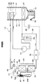
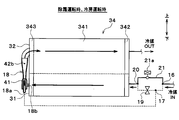
- 1 is an overall configuration diagram of an ejector refrigeration cycle apparatus in a first embodiment. It is sectional drawing of the ejector in 1st Embodiment. It is a schematic diagram of the outdoor heat exchanger unit in 1st Embodiment, and has shown the refrigerant
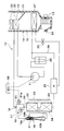
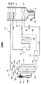
- FIG. 1 is an overall configuration diagram of an ejector refrigeration cycle apparatus according to a first embodiment, showing a refrigerant flow state during cooling operation.
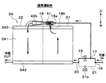
- FIG. 2nd Embodiment It is a schematic diagram of the outdoor heat exchanger unit in 2nd Embodiment, and has shown the refrigerant
- An ejector refrigeration cycle apparatus 10 shown in FIG. 1 is applied to a vehicle air conditioner.
- the vehicle air conditioner is an air conditioner that uses a vehicle interior as a space to be air conditioned.
- the ejector refrigeration cycle apparatus 10 adjusts the temperature of the air blown into the vehicle compartment by cooling or heating the air blown into the vehicle compartment.
- the air blown into the passenger compartment is a temperature adjustment target fluid of the ejector refrigeration cycle apparatus 10.
- the refrigerant of the ejector refrigeration cycle apparatus 10 is an HFC-based refrigerant (specifically, R134a), and the ejector refrigeration cycle apparatus 10 constitutes a subcritical refrigeration cycle.
- the subcritical refrigeration cycle is a refrigeration cycle in which the high-pressure side refrigerant pressure does not exceed the critical pressure of the refrigerant.
- the refrigerant of the ejector refrigeration cycle apparatus 10 may be an HFO refrigerant (specifically, R1234yf) or the like.
- Refrigeration oil for lubricating the compressor 11 is mixed in the refrigerant, and a part of the refrigeration oil circulates in the cycle together with the refrigerant.
- the compressor 11 sucks the refrigerant and discharges it until it becomes a high-pressure refrigerant.
- the compressor 11 is an electric compressor, and a fixed capacity type compression mechanism and an electric motor that drives the compression mechanism are accommodated in the housing of the compressor 11.
- the compression mechanism of the compressor 11 is various compression mechanisms such as a scroll-type compression mechanism and a vane-type compression mechanism.
- the operation (specifically, the rotational speed) of the electric motor of the compressor 11 is controlled by a control signal output from the control device 50.
- the electric motor of the compressor 11 is an AC motor or a DC motor.
- the compressor 11 may be an engine-driven compressor.
- the engine-driven compressor is driven by the rotational driving force transmitted from the vehicle running engine via pulleys, belts, and the like.
- the engine-driven compressor is a variable capacity compressor, a fixed capacity compressor, or the like.
- the variable capacity compressor is a compressor that can adjust the refrigerant discharge capacity by changing the discharge capacity.
- the fixed capacity compressor is a compressor that adjusts the refrigerant discharge capacity by changing the operating rate of the compressor by the on / off of an electromagnetic clutch.
- a radiator 12 is connected to the discharge port side of the compressor 11.
- the radiator 12 is a heat exchanger for heat dissipation that radiates and cools the high-pressure refrigerant by exchanging heat between the high-pressure refrigerant discharged from the compressor 11 and the air blown by the blower 13.
- the blower 13 blows air into the passenger compartment.
- the radiator 12 and the blower 13 are disposed in the casing 15 of the indoor air conditioning unit 14.
- the refrigerant inlet of the first branch portion 16 is connected to the refrigerant outlet side of the radiator 12.
- the first branch portion 16 branches the flow of the refrigerant that has flowed out of the radiator 12.
- the first branch portion 16 is configured by a three-way joint having three inflow / outflow ports, and one of the three inflow / outflow ports is a refrigerant inflow port and the remaining two are refrigerant outflow ports.
- Such a three-way joint may be formed by joining pipes having different pipe diameters, or may be formed by providing a plurality of refrigerant passages in a metal block or a resin block.
- the refrigerant inlet of the second branch part 17 is connected to one refrigerant outlet of the first branch part 16.
- the second branch portion 17 branches the flow of the refrigerant that has flowed out from one refrigerant outlet of the first branch portion 16.
- the second branch portion 17 is configured by a three-way joint having three inflow / outflow ports, and one of the three inflow / outflow ports is a refrigerant inflow port, and the remaining two are refrigerant outflow ports.
- Such a three-way joint may be formed by joining pipes having different pipe diameters, or may be formed by providing a plurality of refrigerant passages in a metal block or a resin block.
- the refrigerant inlet 18 a of the ejector 18 is connected to one refrigerant outlet of the second branch portion 17.
- One refrigerant inlet of the junction 20 is connected to the other refrigerant outlet of the second branch portion 17 via a high-pressure side fixed throttle 19.
- the high-pressure side fixed throttle 19 is a first decompression unit that decompresses the liquid refrigerant flowing out of the radiator 12.
- the high-pressure side fixed throttle 19 is an orifice, a capillary tube, a nozzle, or the like.
- the confluence portion 20 is composed of a three-way joint similar to the first branch portion 16, and two of the three inflow / outflow ports are refrigerant inflow ports and the remaining one is a refrigerant outflow port.
- a three-way joint may be formed by joining pipes having different pipe diameters, or may be formed by providing a plurality of refrigerant passages in a metal block or a resin block.
- the other refrigerant outlet of the first branch part 16 is connected to the other refrigerant inlet of the merge part 20 via the first bypass passage 21.
- a first on-off valve 21 a is disposed in the first bypass passage 21.
- the first bypass passage 21 is a first bypass portion in which the refrigerant heat-exchanged by the radiator 12 bypasses the high-pressure side fixed throttle 19 and the nozzle portion 41 of the ejector 18 and flows to the first outdoor heat exchanger 22.
- the first opening / closing valve 21 a is an opening / closing part that opens and closes the first bypass passage 21.
- the first on-off valve 21a is a solenoid valve. The operation of the first on-off valve 21 a is controlled by a control signal output from the control device 50.
- a refrigerant suction port 18 b of the ejector 18 is connected to the refrigerant outlet of the junction 20 via the first outdoor heat exchanger 22.
- the first outdoor heat exchanger 22 is a heat exchanger that exchanges heat between the high-pressure refrigerant discharged from the compressor 11 and the air outside the vehicle (hereinafter referred to as “outside air”) blown by the outdoor blower 23.
- the first outdoor heat exchanger 22 is arranged on the vehicle front side in the engine room.
- the outdoor blower 23 is an electric blower in which the number of rotations (in other words, the amount of blown air) is controlled by a control voltage output from the control device 50.
- the ejector 18 functions as a pressure reducing unit that depressurizes the high-pressure refrigerant that has flowed out of the radiator 12, and sucks and transports the refrigerant through the suction action of the injected refrigerant that is injected from the nozzle unit 41 at a high speed. It functions as a refrigerant circulation part (in other words, a refrigerant transport part) to be circulated.
- the ejector 18 includes a nozzle part 41 and a body part 42.
- the nozzle portion 41 is formed of a substantially cylindrical metal (for example, a stainless alloy) that gradually tapers in the flow direction of the refrigerant, and isentropically depressurizes the refrigerant that flows into the inside from the refrigerant inlet 18a.
- the refrigerant is injected from the refrigerant injection port 41b provided on the most downstream side of the refrigerant flow.
- a refrigerant passage for reducing the pressure of the refrigerant flowing from the refrigerant inlet 18a is formed inside the nozzle portion 41.
- the refrigerant passage inside the nozzle portion 41 includes a minimum passage area portion 41d having the smallest refrigerant passage area, a tapered portion 41e that gradually reduces the refrigerant passage area toward the minimum passage area portion 41d, and a minimum passage area portion 41d.
- a divergent portion 41f that gradually expands the refrigerant passage area from the refrigerant outlet 41b toward the refrigerant injection port 41b is formed.
- the tapered portion 41e is formed in a truncated cone shape that gradually reduces the refrigerant passage area toward the minimum passage area portion 41d.
- the divergent portion 41f is arranged concentrically with the tapered portion 41e and is formed in a truncated cone shape that gradually increases the refrigerant passage area from the minimum passage area portion 41d toward the refrigerant injection port 41b.
- the body part 42 is formed of a substantially cylindrical metal (for example, aluminum), and forms the outer shell of the ejector 18.
- the body part 42 functions as a fixing member that supports and fixes the nozzle part 41 therein.
- the nozzle portion 41 is fixed by press-fitting or the like so as to be accommodated inside the longitudinal end of the body portion 42.
- a refrigerant suction port 18 b is formed in a portion corresponding to the outer peripheral side of the nozzle portion 41 in the outer peripheral side surface of the body portion 42.
- the refrigerant suction port 18 b is provided so as to penetrate the inside and outside of the body portion 42 and communicate with the refrigerant injection port 41 b of the nozzle portion 41.
- the refrigerant suction port 18 b is a through hole that sucks the refrigerant flowing out of the first outdoor heat exchanger 22 into the ejector 18 by the suction action of the refrigerant injected from the refrigerant injection port 41 b of the nozzle portion 41.
- an inlet space for allowing the refrigerant to flow is formed in the periphery of the refrigerant suction port 18b inside the body portion 42.
- a suction passage 42c is formed between the outer peripheral wall surface around the tapered tip of the nozzle portion 41 and the inner peripheral wall surface of the body portion 42 to guide the suction refrigerant flowing into the body portion 42 to the diffuser portion 42b. Yes.
- the refrigerant passage area of the suction passage 42c is gradually reduced toward the refrigerant flow direction.
- the flow rate of the suction refrigerant flowing through the suction passage 42c is gradually increased, and energy loss (in other words, when the suction refrigerant and the injection refrigerant are mixed in the diffuser portion 42b). Mixing loss).
- the diffuser portion 42b is disposed so as to be continuous with the outlet side of the suction passage 42c, and is formed so that the refrigerant passage area gradually increases.
- the diffuser part 42b fulfill
- the wall surface shape of the inner peripheral wall surface of the body portion 42 forming the diffuser portion 42b is formed by combining a plurality of curves. Since the degree of spread of the refrigerant passage cross-sectional area of the diffuser portion 42b gradually increases in the refrigerant flow direction and then decreases again, the refrigerant can be increased in an isentropic manner.
- a refrigerant inlet of a three-way valve 25 is connected to the refrigerant outlet side of the ejector 18 via a second outdoor heat exchanger 24.
- the second outdoor heat exchanger 24 is a heat exchanger that exchanges heat between the high-pressure refrigerant flowing out from the ejector 18 and the outside air blown by the outdoor blower 23.
- the second outdoor heat exchanger 24 is arranged on the vehicle front side in the engine room.
- the three-way valve 25 has a refrigerant circuit that causes the refrigerant heat-exchanged by the second outdoor heat exchanger 24 to flow out to the refrigerant inlet side of the low-pressure side fixed throttle 26 and the refrigerant heat-exchanged by the second outdoor heat exchanger 24.
- the refrigerant circuit that flows out to the second bypass passage 28 side is switched.
- the second bypass passage 28 is a second bypass part through which the refrigerant heat-exchanged by the second outdoor heat exchanger 24 flows bypassing the low-pressure side fixed throttle 26 and the evaporator 27.
- the three-way valve 25 is an electromagnetic valve that opens and closes the refrigerant passage on the low-pressure side fixed throttle 26 side and the second bypass passage 28. The operation of the three-way valve 25 is controlled by a control signal output from the control device 50.
- One refrigerant outlet of the three-way valve 25 is connected to the refrigerant inlet side of the evaporator 27 via a low pressure side fixed throttle 26.
- the refrigerant outlet side of the evaporator 27 is connected to the refrigerant inlet of the gas-liquid separator 29.
- the other refrigerant outlet of the three-way valve 25 is connected to the refrigerant inlet side of the second bypass passage 28.
- the refrigerant outlet side of the second bypass passage 28 is connected to the refrigerant inlet of the gas-liquid separator 29.
- the gas-liquid separator 29 is a gas-liquid separator that separates the gas-liquid of the refrigerant flowing into the interior.
- the gas-liquid separator 29 has a function as a liquid storage unit that stores the separated liquid-phase refrigerant as an excess liquid-phase refrigerant in the cycle.
- the gas-phase refrigerant outlet of the gas-liquid separator 29 is connected to the suction side of the compressor 11.
- the low-pressure side fixed throttle 26 is a second decompression unit that decompresses the liquid-phase refrigerant that has flowed out of the second outdoor heat exchanger 24.
- the low-pressure side fixed throttle 26 is an orifice, a capillary tube, a nozzle, or the like.
- the evaporator 27 performs heat exchange between the low-pressure refrigerant decompressed by the low-pressure-side fixed restrictor 26 and the air blown from the blower 13 toward the vehicle interior, thereby evaporating the low-pressure refrigerant and exerting an endothermic effect. Heat exchanger.
- the blower 13 is an electric blower in which the number of rotations (in other words, the amount of blown air) is controlled by a control voltage output from the control device 50.
- the evaporator 27 is disposed in the casing 15 of the indoor air conditioning unit 14.
- the indoor air conditioning unit 14 is a unit that blows out the air whose temperature has been adjusted by the ejector refrigeration cycle apparatus 10 into the passenger compartment.
- the indoor air conditioning unit 14 is disposed inside the instrument panel at the forefront of the vehicle interior.
- the outer shell of the indoor air conditioning unit 14 is formed by a casing 15.
- the blower 13, the evaporator 27, the radiator 12, the auxiliary heater 30, the air mix door 31, and the like are accommodated.
- the casing 15 forms an air passage for air blown into the passenger compartment.
- the casing 15 is formed of a resin (for example, polypropylene) having a certain degree of elasticity and excellent in strength.
- the inside / outside air switching device 32 is disposed on the most upstream side of the air flow in the casing 15.
- the inside / outside air switching device 32 is an inside / outside air switching unit that switches and introduces vehicle interior air (hereinafter referred to as inside air) and outside air into the casing 15.
- the inside / outside air switching device 32 has an inside air introduction port, an outside air introduction port, and an inside / outside air switching door.
- the inside air introduction port introduces inside air into the casing 15.
- the outside air introduction port introduces outside air into the casing 15.
- the inside / outside air switching door continuously adjusts the opening area of the inside air introduction port and the outside air introduction port to continuously change the air volume ratio between the inside air volume and the outside air volume.
- the inside / outside air switching door is driven by an electric actuator for the inside / outside air switching door.
- the operation of the electric actuator of the inside / outside air switching door is controlled by a control signal output from the control device 50.
- the blower 13 is arranged on the downstream side of the air flow of the inside / outside air switching device 32.
- the blower 13 is a blower that blows air sucked through the inside / outside air switching device 32 toward the vehicle interior.
- the blower 13 is an electric blower that drives a centrifugal multiblade fan with an electric motor.
- the number of rotations of the blower 13 (in other words, the amount of blown air) is controlled by a control voltage output from the control device 50.
- the evaporator 27, the radiator 12, and the auxiliary heater 30 are arranged in this order with respect to the air flow on the downstream side of the air flow of the blower 13.
- the auxiliary heater 30 is an electric heater that generates heat when power is supplied from the control device 50, and is a heating heat exchanger that heats the air that has passed through the radiator 12.
- the auxiliary heater 30 has a PTC element or a nichrome wire.
- a cold air bypass passage 33 is formed in the casing 15.
- the cold air bypass passage 33 is an air passage that causes the air that has passed through the evaporator 27 to flow downstream by bypassing the radiator 12 and the auxiliary heater 30.
- An air mix door 31 is disposed downstream of the evaporator 27 and upstream of the radiator 12 and the auxiliary heater 30.
- the air mix door 31 is an air volume ratio adjusting unit that adjusts the air volume ratio between the air passing through the evaporator 27 and the air passing through the radiator 12 and the auxiliary heater 30 and the air passing through the cold air bypass passage 33.
- the air mix door 31 is driven by an electric actuator for driving the air mix door.
- the operation of the electric actuator of the air mix door 31 is controlled by a control signal output from the control device 50.
- a mixing space for mixing the air that has passed through the auxiliary heater 30 and the air that has passed through the cold air bypass passage 33 is provided on the downstream side of the air flow of the auxiliary heater 30 and the cold air bypass passage 33.
- An opening hole (not shown) that blows the conditioned air mixed in the mixing space into the vehicle interior, which is the air-conditioning target space, is disposed in the most downstream portion of the air flow of the casing 15.
- face opening holes, foot opening holes, and defroster opening holes are provided as the opening holes.
- the face opening hole blows air-conditioned air toward the upper body of the passenger in the passenger compartment.
- the foot opening hole blows air-conditioned air toward the passenger's feet.
- the defroster opening hole blows conditioned air toward the inner surface of the front window glass of the vehicle.
- the air flow downstream side of the face opening hole, the foot opening hole and the defroster opening hole is respectively connected to a face air outlet (not shown), a foot air outlet (not shown), and a defroster air outlet (not shown) provided in the vehicle interior via a duct (not shown). It is connected to the.
- a face door for adjusting the opening area of the face opening hole
- a foot door for adjusting the opening area of the foot opening hole
- a defroster for adjusting the opening area of the opening hole
- the face door, foot door, and defroster door are outlet mode switching units that switch the outlet mode.
- the face door, the foot door, and the defroster door are connected to an electric actuator for driving the air outlet mode door via a link mechanism and the like, and are rotated in conjunction with each other.
- the operation of the electric actuator for driving the outlet mode door is controlled by a control signal output from the control device 50.
- the control device 50 is composed of a well-known microcomputer including a CPU, ROM, RAM and the like and its peripheral circuits.
- the control device 50 performs various calculations and processes based on the control program stored in the ROM, and controls the operation of various control target devices.
- the control device 50 is connected to a group of sensors for air conditioning control, such as an inside air temperature sensor, an outside air temperature sensor, a solar radiation sensor, an evaporator temperature sensor, an outlet side temperature sensor, and an outlet side pressure sensor. Is entered.
- sensors for air conditioning control such as an inside air temperature sensor, an outside air temperature sensor, a solar radiation sensor, an evaporator temperature sensor, an outlet side temperature sensor, and an outlet side pressure sensor. Is entered.
- the interior air temperature sensor detects the passenger compartment temperature.
- the outside air temperature sensor detects the outside air temperature.
- the solar radiation sensor detects the amount of solar radiation in the passenger compartment.
- the evaporator temperature sensor detects the temperature of air blown from the evaporator 27 (in other words, the temperature of the evaporator).
- the outlet side temperature sensor detects the temperature of the radiator 12 outlet side refrigerant.
- the outlet side pressure sensor detects the pressure of the radiator 12 outlet side refrigerant.
- a control panel (not shown) arranged near the instrument panel at the front of the passenger compartment is connected to the input side of the control device 50. Operation signals from various operation switches provided on the operation panel are input to the control device 50.
- the various operation switches include an air conditioning operation switch and a vehicle interior temperature setting switch.
- the air conditioning operation switch is a switch for requesting that air conditioning in the vehicle interior is performed.
- the vehicle interior temperature setting switch is a switch for setting the vehicle interior temperature.
- the control device 50 is configured integrally with a control unit that controls the operation of various control target devices connected to the output side.
- the configuration (specifically, hardware and software) that controls the operation of each control target device in the control device 50 constitutes a control unit of each control target device.
- the configuration for controlling the operation of the compressor 11 constitutes a discharge capacity control unit.
- the configuration for controlling the operation of the first on-off valve 21a constitutes an on-off control unit.
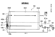
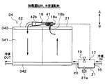
- the first outdoor heat exchanger 22, the second outdoor heat exchanger 24, and the ejector 18 constitute an outdoor heat exchanger unit 34.
- the outdoor heat exchanger unit 34 is a cross flow type heat exchanger in which a refrigerant as an internal fluid flows in a horizontal direction.
- the up and down arrows in FIG. 3 indicate the vertical direction of the vehicle.
- the outdoor heat exchanger unit 34 includes a core part 341 and tank parts 342 and 343.
- the core part 341 is a substantially rectangular heat exchange part including a tube (not shown) and a fin (not shown).
- the tube is a tube through which the refrigerant flows.
- a plurality of tubes are arranged in parallel to each other.
- the plurality of tubes are arranged such that the longitudinal direction thereof coincides with the horizontal direction.
- the plurality of tubes are arranged side by side in the vertical direction.
- the fin is a heat transfer member formed in a wave shape and is joined to the tube.
- the heat transfer area with the air is increased by the fins to promote heat exchange between the refrigerant and the air.
- the tank portions 342 and 343 extend in a direction (vertical direction in the present embodiment) perpendicular to the tube longitudinal direction at end portions in the longitudinal direction of the tubes (end portions in the left-right direction in the present embodiment), and a plurality of tubes. It communicates.
- the tank units 342 and 343 perform distribution and collection of the refrigerant with respect to the plurality of tubes.
- a partition is provided in the tank portions 342 and 343 so that the refrigerant flow direction in the core portion 341 makes a U-turn once. Specifically, a partition is provided between a part constituting the first outdoor heat exchanger 22 and a part constituting the second outdoor heat exchanger 24 in the tank parts 342 and 343. Thereby, the refrigerant
- the ejector 18 is arranged on the side of the core portion 341.
- the ejector 18 is disposed so that the axial direction of the nozzle portion 41 is parallel to the longitudinal direction of the tank portions 342 and 343.
- the ejector 18 is fixed to the outer surfaces of the tank portions 342 and 343.
- the ejector 18 and the outdoor heat exchanger unit 34 are made of an aluminum alloy and are joined to each other by brazing.
- the refrigerant suction port 18 b of the ejector 18 is connected to the tank portions 342 and 343 of the first outdoor heat exchanger 22.
- the refrigerant outlet of the ejector 18 is connected to the tank portions 342 and 343 of the second outdoor heat exchanger 24.
- the control device 50 operates the compressor 11, the blower 13, the outdoor blower 23, and the like. Thereby, the compressor 11 sucks the refrigerant, compresses it, and discharges it.
- the control device 50 determines the operation mode of the ejector-type refrigeration cycle device 10 as one of heating operation, defrosting operation, and cooling operation. For example, the control device 50 determines the operation mode to be either the heating operation or the cooling operation based on the target outlet temperature TAO, and arrives at the first outdoor heat exchanger 22 and the second outdoor heat exchanger 24 in the heating operation. When frost is generated, the defrosting operation is determined.
- the target blowout temperature TAO is a value determined so as to quickly bring the inside air temperature close to the desired target temperature of the occupant, and is calculated by the following mathematical formula.
- TAO Kset ⁇ Tset ⁇ Kr ⁇ Tr ⁇ Kam ⁇ Tam ⁇ Ks ⁇ Ts + C
- Tset is a target temperature in the vehicle interior set by the vehicle interior temperature setting switch
- Tr is the vehicle interior temperature detected by the internal air temperature sensor
- Tam is the outside air temperature detected by the external air temperature sensor.
- Ts is the amount of solar radiation detected by the solar radiation sensor.
- Kset, Kr, Kam, Ks are control gains
- C is a correction constant.
- the control device 50 determines the operation mode as a cooling operation, and when the target blowing temperature TAO is in a high temperature range, the control device 50 determines the operation mode as a heating operation.
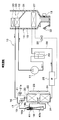
- control device 50 performs control so that the first on-off valve 21a is closed and the three-way valve 25 closes the refrigerant passage on the low-pressure side fixed throttle 26 side and opens the second bypass passage 28.
- control device 50 controls the air mix door 31 to open the air passage on the radiator 12 side and close the cold air bypass passage 33 side.
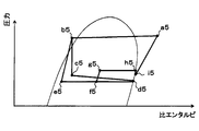
- the high-temperature and high-pressure refrigerant discharged from the compressor 11 flows into the radiator 12 (point a5 in FIG. 5) and is blown from the blower 13.
- the heat exchange is performed, and the heat is dissipated and condensed (point a5 ⁇ b5 in FIG. 5).
- the refrigerant radiated by the radiator 12 flows from the first branching portion 16 to the second branching portion 17 and branches at the second branching portion 17 to the high-pressure side fixed restrictor 19 side and the nozzle portion 41 side of the ejector 18. .
- the refrigerant branched to the high pressure side fixed throttle 19 side at the second branch portion 17 flows into the high pressure side fixed throttle 19 and is decompressed in an isoenthalpy manner (b5 point ⁇ c5 point in FIG. 5).
- the refrigerant depressurized by the high-pressure-side fixed throttle 19 flows into the first outdoor heat exchanger 22, absorbs heat from the outside air blown from the outdoor blower 23, and evaporates (point c5 ⁇ d5 in FIG. 5).
- the refrigerant branched to the nozzle portion 41 side of the ejector 18 at the second branch portion 17 flows into the refrigerant inlet 18a of the nozzle portion 41 of the ejector 18, is decompressed in an isentropic manner, and is discharged from the refrigerant injection port 41b. Injection is performed (b5 point ⁇ e5 point in FIG. 5).
- the refrigerant flowing out of the first outdoor heat exchanger 22 is sucked from the refrigerant suction port 18b by the suction action of the refrigerant injected from the refrigerant injection port 41b.
- the refrigerant injected from the refrigerant injection port 41b and the refrigerant sucked from the refrigerant suction port 18b flow into the diffuser part 42b (point e5 ⁇ f5 point, point d5 ⁇ f5 point in FIG. 5).
- the kinetic energy of the refrigerant is converted into pressure energy by expanding the refrigerant passage area.
- the pressure of the mixed refrigerant rises while the refrigerant injected from the refrigerant injection port 41b and the refrigerant sucked from the refrigerant suction port 18b are mixed (f5 point ⁇ g5 point in FIG. 5).
- the refrigerant flowing out of the diffuser part 42b flows into the second outdoor heat exchanger 24, absorbs heat from the outside air blown from the outdoor blower 23, and evaporates (g5 point ⁇ h5 point in FIG. 5).
- the refrigerant that has flowed out of the second outdoor heat exchanger 24 flows into the gas-liquid separator 29 and is gas-liquid separated (point h5 ⁇ point i5 in FIG. 5).
- the gas-phase refrigerant separated by the gas-liquid separator 29 is sucked from the suction port of the compressor 11 and compressed again (point i5 ⁇ point a5 in FIG. 5).
- the reason why the points h5 and i5 in FIG. 5 are different is that the gas-phase refrigerant flowing out from the gas-liquid separator 29 reaches the suction port of the compressor 11 from the gas-phase refrigerant outlet of the gas-liquid separator 29. This is because pressure loss occurs when circulating through the refrigerant piping. Therefore, in an ideal cycle, it is desirable that the points h5 and i5 coincide.
- the ejector refrigeration cycle apparatus 10 operates as described above in the heating operation, and can heat the air blown into the passenger compartment.
- the ejector type refrigeration cycle apparatus 10 causes the compressor 11 to suck the refrigerant whose pressure has been increased by the diffuser portion 42b of the ejector 18 during the heating operation. ) Can be improved.
- the refrigerant pressure of the first outdoor heat exchanger 22 can be lowered by the amount that the ejector 18 pressurizes the refrigerant, the heat absorption capability of the first outdoor heat exchanger 22 can be improved, and thus the heating capability can be improved.
- control device 50 controls the first on-off valve 21a to open and the three-way valve 25 to close the refrigerant passage on the low-pressure side fixed throttle 26 side and open the second bypass passage 28.
- control device 50 controls the air mix door 31 to close the radiator 12 side and open the cold air bypass passage 33 side.
- the high-temperature and high-pressure refrigerant discharged from the compressor 11 flows into the radiator 12 and flows out of the radiator 12 without exchanging heat. This is because the air blown from the blower 13 passes through the cold air bypass passage 33 without passing through the radiator 12.
- the refrigerant that has flowed out of the radiator 12 flows through the first branch portion 16 ⁇ the first bypass passage 21 ⁇ the merging portion 20 through a path having a small passage resistance, and the first outdoor heat exchanger 22 flows in.
- the refrigerant flowing into the first outdoor heat exchanger 22 exchanges heat with the outside air blown from the outdoor blower 23, dissipates heat, and condenses.
- the refrigerant radiated by the first outdoor heat exchanger 22 flows into the refrigerant suction port 18b of the ejector 18 and flows out from the diffuser portion 42b. Since the refrigerant does not flow into the nozzle portion 41 of the ejector 18, the ejector 18 functions as a simple refrigerant flow path without fulfilling the functions as the decompression portion and the refrigerant circulation portion.
- the refrigerant that has flowed out of the diffuser portion 42b flows into the second outdoor heat exchanger 24, exchanges heat with the outside air blown from the outdoor blower 23, dissipates heat, and condenses.
- the refrigerant dissipated in the second outdoor heat exchanger 24 flows into the gas-liquid separator 29 and is gas-liquid separated.
- the gas-phase refrigerant separated by the gas-liquid separator 29 is sucked from the suction port of the compressor 11 and compressed again.
- the ejector refrigeration cycle apparatus 10 operates as described above in the defrosting operation, and the high-temperature refrigerant flows through the first outdoor heat exchanger 22 and the second outdoor heat exchanger 24. Therefore, the first outdoor heat exchanger 22 and the second outdoor heat exchanger 22 The frost adhering to the two outdoor heat exchangers 24 can be melted and defrosted.
- control device 50 controls the first on-off valve 21a to open, and the three-way valve 25 to open the refrigerant passage on the low-pressure side fixed throttle 26 side and close the second bypass passage 28.
- control device 50 controls the air mix door 31 to a predetermined opening.
- the high-temperature and high-pressure refrigerant discharged from the compressor 11 flows into the radiator 12.
- the air mix door 31 closes the radiator 12 side
- the refrigerant flowing into the radiator 12 flows out of the radiator 12 without exchanging heat.
- the air mix door 31 opens the radiator 12 side
- the refrigerant flowing into the radiator 12 exchanges heat with the air blown from the blower 13, and dissipates and condenses.
- the refrigerant that has flowed out of the radiator 12 flows through the first branch portion 16 ⁇ the first bypass passage 21 ⁇ the merging portion 20 through a path having a small passage resistance, and the first outdoor heat exchanger 22 flows in.
- the refrigerant flowing into the first outdoor heat exchanger 22 exchanges heat with the outside air blown from the outdoor blower 23, dissipates heat, and condenses.
- the refrigerant radiated by the first outdoor heat exchanger 22 flows into the refrigerant suction port 18b of the ejector 18 and flows out from the diffuser portion 42b. Since the refrigerant does not flow into the nozzle portion 41 of the ejector 18, the ejector 18 functions as a simple refrigerant flow path without fulfilling the functions as the decompression portion and the refrigerant circulation portion.
- the refrigerant that has flowed out of the diffuser portion 42b flows into the second outdoor heat exchanger 24, absorbs heat from the outside air blown from the outdoor blower 23, and evaporates.
- the refrigerant that has flowed out of the second outdoor heat exchanger 24 is decompressed in an enthalpy manner by the low-pressure-side fixed restrictor 26 and flows into the evaporator 27.
- the refrigerant flowing into the evaporator 27 absorbs heat from the air blown from the blower 13 and evaporates. Thereby, the air blown into the passenger compartment is cooled.
- the refrigerant that has flowed out of the evaporator 27 flows into the gas-liquid separator 29 and is gas-liquid separated.
- the gas-phase refrigerant separated by the gas-liquid separator 29 is sucked from the suction port of the compressor 11 and compressed again.
- the ejector refrigeration cycle apparatus 10 operates as described above in the cooling operation, and can cool the air blown into the passenger compartment.
- the compressor 11 sucks and compresses and discharges the refrigerant.
- the radiator 12 exchanges heat between the refrigerant compressed by the compressor 11 and the air blown into the passenger compartment.
- the high pressure side fixed throttle 19 depressurizes the refrigerant heat-exchanged by the radiator 12.
- the first outdoor heat exchanger 22 exchanges heat between the refrigerant decompressed by the high pressure side fixed throttle 19 and the outside air.
- the ejector 18 decompresses the refrigerant flowing out of the radiator 12 at the nozzle portion 41, sucks the refrigerant from the refrigerant suction port 18 b by the suction action of the jetted refrigerant injected from the nozzle portion 41, and sucks it from the jetted refrigerant and the refrigerant suction port.
- the sucked refrigerant thus mixed is mixed and boosted by the booster 42b.
- the second outdoor heat exchanger 24 exchanges heat between the refrigerant pressurized by the ejector 18 and the outside air.
- the second branch part 17 branches the refrigerant heat-exchanged by the radiator 12 to the high-pressure side fixed throttle 19 side and the nozzle part 41 side of the ejector 18.
- the refrigerant heat-exchanged by the radiator 12 bypasses the high-pressure side fixed throttle 19 and the nozzle portion 41 of the ejector 18 and flows to the first outdoor heat exchanger 22.
- the first on-off valve 21 a opens and closes the first bypass passage 21.
- the refrigerant absorbs heat from the outside air in the first outdoor heat exchanger 22 and the second outdoor heat exchanger 24, and the refrigerant is air-conditioned in the radiator 12. Since heat is radiated to the air blown to the air, heating operation can be realized.
- the first on-off valve 21a opens the first bypass passage 21, it is possible to realize an operation (specifically, a defrosting operation and a cooling operation) in which heat is radiated to the outside air by the first outdoor heat exchanger 22 and the second outdoor heat exchanger 24. .
- the heating capacity and cycle efficiency can be improved by the boosting effect of the ejector 18.
- the first outdoor heat exchanger 22 can evaporate the refrigerant at an evaporation pressure lower than the compressor suction pressure by an amount corresponding to the pressure increasing effect in the ejector 18.
- the refrigerant evaporation temperature at 22 can be lowered. Therefore, the heating capacity can be improved. Further, since the suction pressure of the compressor 11 can be increased by the boosting effect of the ejector 18, the driving power of the compressor 11 can be reduced, and the cycle efficiency can be improved.
- the heating capacity and cycle efficiency during the heating operation Both can be improved.
- the low pressure side fixed throttle 26 depressurizes the refrigerant heat-exchanged by the second outdoor heat exchanger 24.
- the evaporator 27 exchanges heat between the refrigerant decompressed by the low-pressure side fixed throttle 26 and the air blown into the passenger compartment.
- the refrigerant heat-exchanged by the second outdoor heat exchanger 24 flows by bypassing the low-pressure side fixed throttle 26 and the evaporator 27.
- the switching unit 25 is configured so that the refrigerant heat-exchanged in the second outdoor heat exchanger 24 flows through the low-pressure side fixed throttle 26 and the evaporator 27 and is sucked into the compressor 11, and heat is generated in the second outdoor heat exchanger 24.
- the state where the exchanged refrigerant flows through the second bypass passage 28 and is sucked into the compressor 11 is switched.
- the switching unit 25 switches the refrigerant flow, whereby the air blown into the passenger compartment is cooled and dehumidified by the second outdoor heat exchanger 24.
- the operation to be performed specifically, the cooling operation
- the operation in which the air blown into the vehicle interior is not cooled and dehumidified by the second outdoor heat exchanger 24 specifically, the defrosting operation
- the ejector 18 is fixed to the first outdoor heat exchanger 22 and the second outdoor heat exchanger 24. Therefore, since the 1st outdoor heat exchanger 22, the 2nd outdoor heat exchanger 24, and the ejector 18 become one heat exchanger unit 34, the structure of the ejector-type refrigeration cycle apparatus 10 can be simplified.
- the ejector 18 is arranged such that the axial direction of the nozzle portion 41 is parallel to the longitudinal direction of the tank portions 342 and 343 of the first outdoor heat exchanger 22 and the second outdoor heat exchanger 24. Yes. Thereby, the physique of the heat exchanger unit 34 can be reduced in size.
- the first outdoor heat exchanger 22 and the second outdoor heat exchanger 24 are configured such that the refrigerant flows in the horizontal direction in the core portion 341, and the ejector 18 is disposed on the side of the core portion 341. Has been placed.
- the physique of the heat exchanger unit 34 having the so-called crossflow type first outdoor heat exchanger 22 and the second outdoor heat exchanger 24 can be reduced in size.
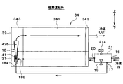
- the outdoor heat exchanger unit 34 is a cross flow type heat exchanger in which the refrigerant as the internal fluid flows in the horizontal direction.
- the heat exchanger unit 34 is a downflow type heat exchanger in which a refrigerant as an internal fluid flows in the vertical direction.
- the tube of the core part 341 of the outdoor heat exchanger unit 34 is arranged in parallel with each other.
- the plurality of tubes are arranged such that the longitudinal direction thereof coincides with the vertical direction.
- the plurality of tubes are arranged side by side in the horizontal direction.
- the tank portions 342 and 343 of the outdoor heat exchanger unit 34 are arranged in a direction (horizontal direction in the present embodiment) orthogonal to the longitudinal direction of the tube at an end portion in the longitudinal direction of the tube (end portion in the vertical direction in the present embodiment). ).
- the refrigerant flow direction in the core part 341 of the first outdoor heat exchanger 22 and the refrigerant flow direction in the core part 341 of the second outdoor heat exchanger 24 are opposite to each other.
- the ejector 18 is disposed above the core portion 341.
- the ejector 18 is disposed so that the axial direction of the nozzle portion 41 is parallel to the longitudinal direction of the tank portions 342 and 343.
- the ejector 18 is fixed to the outer surfaces of the tank portions 342 and 343.
- the ejector 18 and the outdoor heat exchanger unit 34 are made of an aluminum alloy and are joined to each other by brazing.
- the refrigerant suction port 18 b of the ejector 18 is connected to the tank portions 342 and 343 of the first outdoor heat exchanger 22.
- the refrigerant outlet of the ejector 18 is connected to the tank portions 342 and 343 of the second outdoor heat exchanger 24.
- the first outdoor heat exchanger 22 and the second outdoor heat exchanger 24 are configured such that the refrigerant flows in the vertical direction in the core portion 341, and the ejector 18 is configured so as to be connected to the outdoor heat exchanger unit 34. It is disposed above the core part 341. Thereby, the physique of the heat exchanger unit 34 which has what is called a downflow type 1st outdoor heat exchanger 22 and the 2nd outdoor heat exchanger 24 can be reduced in size.
- the ejector 18 is provided outside the tank portions 342 and 343 of the outdoor heat exchanger unit 34.
- the ejector 18 is provided outside the tank portions 342 and 343 of the outdoor heat exchanger unit 34.
- FIGS. May be accommodated in the tank portions 342 and 343 of the outdoor heat exchanger unit 34.
- the size of the heat exchanger unit 34 can be further reduced, and the piping structure between the first outdoor heat exchanger 22 and the second outdoor heat exchanger 24 and the ejector 18 can be simplified.
- the outdoor heat exchanger unit 34 may have a vertically symmetric configuration with respect to the second embodiment. That is, the first outdoor heat exchanger 22 and the second outdoor heat exchanger 24 are configured such that the refrigerant flows in the vertical direction at the core portion 341, and the ejector 18 is configured to have the core portion 341 of the outdoor heat exchanger unit 34. It may be arranged below. Thereby, there can exist an effect similar to the said 2nd Embodiment.
- the partition is provided in the tank parts 342 and 343 so that the refrigerant flow direction in the core part 341 of the outdoor heat exchanger unit 34 makes a U-turn once, but the outdoor heat exchanger unit Partitions may be provided in the tank portions 342 and 343 so that the refrigerant flow direction in the core portion 341 of the 34 U-turns a plurality of times.
- the application of the ejector refrigeration cycle apparatus 10 described in the above embodiment is not limited to a vehicle air conditioner.
- the present invention may be applied to a stationary air conditioner, a freezer / refrigerator and the like.
- the ejector 18 has a fixed nozzle portion in which the refrigerant passage area of the minimum passage area portion does not change, but the refrigerant passage area of the minimum passage area portion is changed as the ejector 18.
- variable nozzle portion has a configuration in which a needle-like or conical valve body is disposed in the passage of the variable nozzle portion, and the valve passage is displaced by an electric actuator or the like to adjust the refrigerant passage area.
- fixed throttles are adopted as the high-pressure side fixed throttle 19 and the low-pressure side fixed throttle 26.
- a temperature type expansion valve or an electric expansion is used as the high-pressure side fixed throttle 19 and the low-pressure side fixed throttle 26.
- a variable throttle mechanism such as a valve may be employed.
- R134a or R1234yf or the like is adopted as the refrigerant, but the refrigerant is not limited to this.
- R600a, R410A, R404A, R32, R1234yfxf, R407C, or the like may be employed as the refrigerant.
- a mixed refrigerant obtained by mixing a plurality of kinds of refrigerants among these refrigerants may be employed.
Landscapes
- Engineering & Computer Science (AREA)
- Physics & Mathematics (AREA)
- Thermal Sciences (AREA)
- Mechanical Engineering (AREA)
- General Engineering & Computer Science (AREA)
- Air-Conditioning For Vehicles (AREA)
Priority Applications (3)
| Application Number | Priority Date | Filing Date | Title |
|---|---|---|---|
| CN201780035349.0A CN109312960A (zh) | 2016-06-08 | 2017-04-27 | 喷射器式制冷循环装置 |
| DE112017002892.2T DE112017002892T5 (de) | 2016-06-08 | 2017-04-27 | Ejektor-Kühlkreisvorrichtung |
| US16/307,272 US10759258B2 (en) | 2016-06-08 | 2017-04-27 | Ejector refrigeration cycle device |
Applications Claiming Priority (2)
| Application Number | Priority Date | Filing Date | Title |
|---|---|---|---|
| JP2016114240A JP2017219262A (ja) | 2016-06-08 | 2016-06-08 | エジェクタ式冷凍サイクル装置 |
| JP2016-114240 | 2016-06-08 |
Publications (1)
| Publication Number | Publication Date |
|---|---|
| WO2017212820A1 true WO2017212820A1 (ja) | 2017-12-14 |
Family
ID=60577791
Family Applications (1)
| Application Number | Title | Priority Date | Filing Date |
|---|---|---|---|
| PCT/JP2017/016680 Ceased WO2017212820A1 (ja) | 2016-06-08 | 2017-04-27 | エジェクタ式冷凍サイクル装置 |
Country Status (5)
| Country | Link |
|---|---|
| US (1) | US10759258B2 (enExample) |
| JP (1) | JP2017219262A (enExample) |
| CN (1) | CN109312960A (enExample) |
| DE (1) | DE112017002892T5 (enExample) |
| WO (1) | WO2017212820A1 (enExample) |
Families Citing this family (4)
| Publication number | Priority date | Publication date | Assignee | Title |
|---|---|---|---|---|
| US10760838B2 (en) * | 2017-12-20 | 2020-09-01 | Lennox Industries Inc. | Method and apparatus for refrigerant detector calibration confirmation |
| WO2019155805A1 (ja) * | 2018-02-08 | 2019-08-15 | 株式会社デンソー | エジェクタ式冷凍サイクル、および流量調整弁 |
| JP7031482B2 (ja) * | 2018-02-08 | 2022-03-08 | 株式会社デンソー | エジェクタ式冷凍サイクル、および流量調整弁 |
| JP7135450B2 (ja) * | 2018-05-31 | 2022-09-13 | 株式会社デンソー | 冷凍サイクル装置 |
Citations (6)
| Publication number | Priority date | Publication date | Assignee | Title |
|---|---|---|---|---|
| JP2006118849A (ja) * | 2004-09-22 | 2006-05-11 | Denso Corp | エジェクタ式冷凍サイクル |
| JP2007057222A (ja) * | 2005-04-05 | 2007-03-08 | Denso Corp | エジェクタ式冷凍サイクル用ユニット |
| US20110120182A1 (en) * | 2008-01-18 | 2011-05-26 | Roland Haussmann | Plate Evaporator, In Particular For A Refrigerant Circuit |
| JP2012242020A (ja) * | 2011-05-20 | 2012-12-10 | Denso Corp | ヒートポンプ装置 |
| JP2014016085A (ja) * | 2012-07-09 | 2014-01-30 | Denso Corp | 冷凍サイクル装置 |
| JP2014156143A (ja) * | 2013-02-14 | 2014-08-28 | Panasonic Corp | 車両用空調装置 |
Family Cites Families (6)
| Publication number | Priority date | Publication date | Assignee | Title |
|---|---|---|---|---|
| JP3486851B2 (ja) | 1993-05-28 | 2004-01-13 | 株式会社ゼクセルヴァレオクライメートコントロール | 空気調和装置 |
| JP5625610B2 (ja) * | 2010-08-18 | 2014-11-19 | 株式会社デンソー | エジェクタ式冷凍サイクル本発明は、エジェクタを備えるエジェクタ式冷凍サイクルに関する。 |
| JP5831423B2 (ja) * | 2012-10-08 | 2015-12-09 | 株式会社デンソー | 冷凍サイクル装置 |
| JP6011507B2 (ja) * | 2013-10-08 | 2016-10-19 | 株式会社デンソー | 冷凍サイクル装置 |
| CN203964434U (zh) * | 2014-03-27 | 2014-11-26 | 广东美的暖通设备有限公司 | 热泵空调器 |
| JP6193955B2 (ja) | 2014-12-11 | 2017-09-06 | Ckd株式会社 | 流体制御バルブ |
-
2016
- 2016-06-08 JP JP2016114240A patent/JP2017219262A/ja active Pending
-
2017
- 2017-04-27 US US16/307,272 patent/US10759258B2/en active Active
- 2017-04-27 WO PCT/JP2017/016680 patent/WO2017212820A1/ja not_active Ceased
- 2017-04-27 DE DE112017002892.2T patent/DE112017002892T5/de active Pending
- 2017-04-27 CN CN201780035349.0A patent/CN109312960A/zh active Pending
Patent Citations (6)
| Publication number | Priority date | Publication date | Assignee | Title |
|---|---|---|---|---|
| JP2006118849A (ja) * | 2004-09-22 | 2006-05-11 | Denso Corp | エジェクタ式冷凍サイクル |
| JP2007057222A (ja) * | 2005-04-05 | 2007-03-08 | Denso Corp | エジェクタ式冷凍サイクル用ユニット |
| US20110120182A1 (en) * | 2008-01-18 | 2011-05-26 | Roland Haussmann | Plate Evaporator, In Particular For A Refrigerant Circuit |
| JP2012242020A (ja) * | 2011-05-20 | 2012-12-10 | Denso Corp | ヒートポンプ装置 |
| JP2014016085A (ja) * | 2012-07-09 | 2014-01-30 | Denso Corp | 冷凍サイクル装置 |
| JP2014156143A (ja) * | 2013-02-14 | 2014-08-28 | Panasonic Corp | 車両用空調装置 |
Also Published As
| Publication number | Publication date |
|---|---|
| CN109312960A (zh) | 2019-02-05 |
| DE112017002892T5 (de) | 2019-02-14 |
| US20190217684A1 (en) | 2019-07-18 |
| JP2017219262A (ja) | 2017-12-14 |
| US10759258B2 (en) | 2020-09-01 |
Similar Documents
| Publication | Publication Date | Title |
|---|---|---|
| JP6547781B2 (ja) | 冷凍サイクル装置 | |
| CN105121977B (zh) | 制冷循环装置 | |
| JP6277888B2 (ja) | 冷凍サイクル装置 | |
| JP6011507B2 (ja) | 冷凍サイクル装置 | |
| CN109416203B (zh) | 喷射器式制冷循环 | |
| JP2013068407A (ja) | 冷凍サイクル装置 | |
| JP6708161B2 (ja) | エジェクタ式冷凍サイクル | |
| WO2014076905A1 (ja) | 冷凍サイクル装置 | |
| US11480197B2 (en) | Ejector module | |
| WO2017212820A1 (ja) | エジェクタ式冷凍サイクル装置 | |
| JP7135583B2 (ja) | 冷凍サイクル装置 | |
| JP2019105422A (ja) | 車両用ジョイントブロック | |
| JP6225709B2 (ja) | 空調装置 | |
| WO2017217142A1 (ja) | 冷凍サイクル装置 | |
| JP6642297B2 (ja) | エジェクタ式冷凍サイクル | |
| JP7468237B2 (ja) | 冷凍サイクル装置 | |
| WO2019017169A1 (ja) | エジェクタモジュール | |
| JP2016050761A (ja) | エジェクタ式冷凍サイクル | |
| JP6720932B2 (ja) | エジェクタ式冷凍サイクル | |
| JP7768378B2 (ja) | ヒートポンプサイクル装置 | |
| WO2018159321A1 (ja) | エジェクタモジュール |
Legal Events
| Date | Code | Title | Description |
|---|---|---|---|
| 121 | Ep: the epo has been informed by wipo that ep was designated in this application |
Ref document number: 17810002 Country of ref document: EP Kind code of ref document: A1 |
|
| 122 | Ep: pct application non-entry in european phase |
Ref document number: 17810002 Country of ref document: EP Kind code of ref document: A1 |