WO2017204068A1 - Dispositif à ressort à gaz - Google Patents
Dispositif à ressort à gaz Download PDFInfo
- Publication number
- WO2017204068A1 WO2017204068A1 PCT/JP2017/018622 JP2017018622W WO2017204068A1 WO 2017204068 A1 WO2017204068 A1 WO 2017204068A1 JP 2017018622 W JP2017018622 W JP 2017018622W WO 2017204068 A1 WO2017204068 A1 WO 2017204068A1
- Authority
- WO
- WIPO (PCT)
- Prior art keywords
- piston
- gas spring
- rod
- spring device
- push rod
- Prior art date
Links
Images


Classifications
-
- F—MECHANICAL ENGINEERING; LIGHTING; HEATING; WEAPONS; BLASTING
- F16—ENGINEERING ELEMENTS AND UNITS; GENERAL MEASURES FOR PRODUCING AND MAINTAINING EFFECTIVE FUNCTIONING OF MACHINES OR INSTALLATIONS; THERMAL INSULATION IN GENERAL
- F16F—SPRINGS; SHOCK-ABSORBERS; MEANS FOR DAMPING VIBRATION
- F16F9/00—Springs, vibration-dampers, shock-absorbers, or similarly-constructed movement-dampers using a fluid or the equivalent as damping medium
- F16F9/32—Details
- F16F9/56—Means for adjusting the length of, or for locking, the spring or damper, e.g. at the end of the stroke
Definitions
- the present invention relates to a gas spring device suitable for use in, for example, a back angle adjustment mechanism, a height adjustment mechanism, and the like equipped in a chair, a bed, and the like.
- a gas spring device is used for a back angle adjustment mechanism that adjusts the angle of the backrest of the chair and a height adjustment mechanism that adjusts the height of the seat portion of the chair.
- This gas spring device pushes the end of the push rod protruding from the piston rod into the piston rod by a rotatable external lever.
- the valve part provided in the push rod part can be opened and closed, and the expansion-contraction dimension of the piston rod part can be adjusted (for example, refer patent document 1).
- the gas spring device according to Patent Document 1 is configured such that the end of the push rod protruding from the piston rod is pushed by a rotatable external lever.
- the external lever abuts obliquely against the end of the push rod portion, so that a lateral force may be applied to the push rod portion.
- a lateral force is applied to the push rod part, the push rod part is pressed against the inner peripheral surface of the piston rod part and the sliding resistance increases, so that the operability of the push rod part may be deteriorated.
- An object of the present invention is to provide a gas spring device that can improve the operability of the push rod part by reducing the sliding resistance of the push rod part with respect to the piston rod part.
- a gas spring device includes a cylinder in which pressurized gas is sealed, and a piston portion that is slidably inserted into the cylinder and defines the inside of the cylinder in two chambers.
- a piston rod portion having one end connected to the piston portion and the other end extending to the outside of the cylinder, a communication passage communicating the two chambers formed in the cylinder, and opening and closing the communication passage
- a gas spring device comprising a push rod portion having a valve portion, wherein the push rod portion is operated from outside to open the communication path and adjust an axial length of the piston rod portion with respect to the cylinder; Of the push rod portion, at least the end portion on the side opposite to the piston portion is formed using a resin material.
- the sliding resistance of the push rod part with respect to the piston rod part can be reduced, and the operability of the push rod part can be improved.
- the gas spring device according to the embodiment of the present invention is applied to a back angle adjustment mechanism that adjusts the angle of the backrest of a chair
- the mounting eye is arranged on the upper side and the piston rod part is arranged on the lower side
- the configuration of each part is described according to the upper position and the lower position.
- the mounting eye can be disposed on the lower side
- the piston rod portion can be disposed on the upper side
- the gas spring device can be used while being tilted sideways.
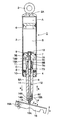
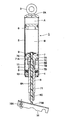
- the gas spring device 1 can elastically support a chair back (not shown) and adjust the angle of the back.
- the gas spring device 1 includes a cylinder 2, a piston portion 7, a piston rod portion 8, a communication passage 9, and a push rod portion 12 which will be described later.
- the cylinder 2 is formed as a cylindrical body that forms the outer shell of the gas spring device 1.
- the upper end of the cylinder 2 is gas-liquid tightly closed by the cap 2A.
- An attachment eye 3 for attaching the cylinder 2 to one fixed portion (not shown) is attached to the cap 2A.
- a rod guide 4 is fixed by caulking to the lower end side of the cylinder 2.
- This rod guide 4 supports the piston rod part 8 so that sliding is possible,
- the seal member 5 which seals between the piston rod parts 8 fluid-tightly is provided in the upper position.
- the free piston 6 is located on the upper side of the cylinder 2 and is slidably inserted into the cylinder 2.
- the free piston 6 defines a gas chamber A between itself and the cap 2 ⁇ / b> A, and pressurized gas is sealed in the gas chamber A.
- hydraulic oil is sealed between the free piston 6 and the seal member 5.
- the piston part 7 is provided in the cylinder 2.
- the piston portion 7 is formed in a stepped cylindrical shape by, for example, cutting a metal material.
- the piston portion 7 includes a thick cylindrical partition wall portion 7A inserted in the cylinder 2 so as to be slidable in the axial direction, and a cylindrical shaft extending downward from the center of the partition wall portion 7A.
- Part 7B The partition wall portion 7 ⁇ / b> A defines the inside of the cylinder 2 into two chambers: an upper oil chamber B between the free piston 6 and a lower oil chamber C between the seal member 5.
- a small-diameter hole 7C extending in the axial direction across the shaft portion 7B and a large-diameter hole 7D extending in the axial direction by expanding the lower end of the small-diameter hole 7C are provided at the axial center of the partition wall portion 7A. It has been. Further, a passage portion 7E that connects the small diameter hole 7C and the lower oil chamber C is formed in the piston portion 7. In the passage portion 7E, one end on the inner diameter side of the piston portion 7 opens at an upper portion of the small diameter hole 7C, and the other end on the outer diameter side opens on the outer peripheral surface of the shaft portion 7B.
- the small-diameter hole 7C of the piston portion 7 forms a valve seat portion that is opened and closed by a valve member 13 of the push rod portion 12 described later.
- the small diameter hole 7C constitutes an insertion hole 10 described later, and the small diameter hole 7C and the passage portion 7E constitute a communication path 9 described later.
- the piston rod portion 8 is formed as a hollow rod-like body extending in the axial direction of the cylinder 2.
- the piston rod portion 8 is formed, for example, as a stepped cylindrical body having a small diameter and a long diameter by cutting a metal material.
- the piston rod portion 8 is configured integrally with the piston portion 7 by caulking and fixing the upper end side to the large-diameter hole 7D of the piston portion 7 in the cylinder 2.
- the lower end side of the piston rod portion 8 extends to the outside of the cylinder 2 via the seal member 5 and the rod guide 4.
- the piston rod portion 8 is formed with a rod hole 8A located at the center of the axis. Further, the piston rod portion 8 is formed with an enlarged diameter accommodating portion 8B that is located at the upper end portion of the rod hole 8A and accommodates a later-described bearing 11 and the like. On the other hand, on the lower end side of the piston rod portion 8, a screw portion 8C for attaching the piston rod portion 8 to another fixing portion (not shown) is formed.
- the communication passage 9 communicates the upper oil chamber B and the lower oil chamber C formed in the cylinder 2.
- the communication passage 9 is formed by the upper portion of the small diameter hole 7C of the piston portion 7 and the passage portion 7E.
- the insertion hole 10 is provided so as to penetrate the piston portion 7 and the piston rod portion 8 in the axial direction.
- the insertion hole 10 is constituted by a small diameter hole 7 ⁇ / b> C of the piston portion 7 and a rod hole 8 ⁇ / b> A of the piston rod portion 8.
- a push rod portion 12 described later is inserted into the insertion hole 10 so as to be movable in the axial direction.
- the bearing 11 is inserted into the small diameter hole 7 ⁇ / b> C of the piston portion 7.
- the bearing 11 is configured as a sliding bearing formed in a cylindrical shape from a material having self-lubricating properties.
- the bearing 11 supports the lower part of the valve member 13 constituting the push rod portion 12 so as to be movable in the axial direction.
- the push rod portion 12 is operated from the outside to communicate (open) or block (close) the communication passage 9 between the upper oil chamber B and the lower oil chamber C.
- the push rod portion 12 includes a valve member 13, a rod member 14, and a cap member 15 which will be described later.
- the valve member 13 is disposed across the small diameter hole 7C of the piston portion 7 and the rod hole 8A (expanded diameter accommodating portion 8B) of the piston rod portion 8.
- the valve member 13 constitutes a rod body together with a rod member 14 to be described later, and constitutes a valve portion.
- the valve member 13 is formed as a metal stepped rod-like body, and is inserted into the axial center positions of the piston portion 7 and the piston rod portion 8 so as to be movable in the axial direction.
- a reduced diameter portion 13A is provided at a position near the upper side of the valve member 13 so as to face the passage portion 7E.
- the reduced diameter portion 13A is formed in such a manner that the outer peripheral surface of the valve member 13 located above and below the reduced diameter portion 13A is in fluid-tight sliding contact with the small diameter hole 7C of the piston portion 7, thereby An annular passage 13B can be formed between the two.
- the upper end surface of the valve member 13 receives the pressure in the upper oil chamber B, and is biased in the direction of arrow a (downward) by the pressure difference from the lower end surface that has received the atmospheric pressure. Yes.
- the annular passage 13B communicates with the upper oil chamber B by the valve member 13 being pushed together with the rod member 14 and the like in a direction indicated by an arrow b (upward).
- the piston portion 7 can be freely moved in the axial direction with respect to the cylinder 2.
- the protrusion dimension of the piston rod part 8 with respect to the cylinder 2 ie, the angle of the backrest, can be adjusted.
- the rod member 14 constitutes a rod body together with the valve member 13, and is inserted into the insertion hole 10 together with the valve member 13 so as to be movable in the axial direction.
- the rod member 14 is formed as a metal stepped rod like the valve member 13.
- the rod member 14 is in contact with the lower end surface of the valve member 13 at the upper end surface on the piston portion 7 side.
- the lower end of the rod member 14 on the side opposite to the piston 7 is reduced in diameter from the stepped portion 14A, and this portion is a small-diameter shaft portion 14B.
- the small-diameter shaft portion 14 ⁇ / b> B forms a support for attaching a cap member 15 described later, and is press-fitted into the attachment hole 15 ⁇ / b> B of the cap member 15.
- the cap member 15 is provided at the lower end of the rod member 14 on the side opposite to the piston 7.
- the cap member 15 prevents the lower portion of the push rod portion 12 from being laterally displaced (displaced in the radial direction) when pressed from below by an external lever 16 described later.
- the cap member 15 is formed in a bottomed cylindrical shape with a resin material such as graphite having self-lubricating properties, such as graphite, tetrafluoroethylene (PTFE), molybdenum disulfide, and tungsten disulfide, and protrudes from the piston rod portion 8. And attached to the rod member 14. More specifically, the cap member 15 has a bullet shape in which the lower end portion 15A has a convex spherical shape.
- the outer diameter dimension (diameter dimension) of the cap member 15 is set to be approximately the same as the outer diameter dimension of the rod member 14, preferably slightly larger than the outer diameter dimension of the rod member 14.
- the cap hole made of a resin material having self-lubricating property before the metal rod member 14 is formed in the rod hole 8A. 15 can be brought into contact.
- a mounting hole 15B is formed by opening upward.
- the small diameter shaft portion 14B of the rod member 14 is press-fitted into the mounting hole 15B.
- the cap member 15 can always make the contact state with the external lever 16 constant by making the lower end portion 15A have a convex spherical shape.
- the external lever 16 is attached to the other fixed part mentioned above so that rotation is possible via the pin 16A. Therefore, the external lever 16 can push the push rod portion 12 in the direction indicated by the arrow b by rotating the other end portion in the direction indicated by the arrow c with the pin 16A as a fulcrum. In this state, the protruding dimension (expansion / contraction amount) of the piston rod portion 8 relative to the cylinder 2 can be adjusted.
- the gas spring device 1 according to the first embodiment is configured as described above. Next, the operation of the gas spring device 1 will be described.
- the push rod portion 12 causes the upper oil chamber B and the lower oil chamber C to communicate with each other when the annular passage 13B of the valve member 13 reaches the upper oil chamber B.
- the piston portion 7 is free to move in the axial direction with respect to the cylinder 2. Therefore, by pushing the cylinder 2 in the direction of arrow a, the piston rod portion 8 can be pushed into the cylinder 2 and reduced.
- the piston rod portion 8 can be extended from the cylinder 2 by pulling the cylinder 2 in the direction indicated by the arrow b.
- the external lever 16 when the external lever 16 is rotated to push the push rod portion 12, the external lever 16 does not contact the push rod portion 12 at a right angle, and the external lever has an angle ⁇ larger than the right angle. 16 contacts the lower part of the push rod part 12.
- This angle ⁇ is, for example, about 45 degrees.
- a lateral force that is, a force that pushes the push rod portion 12 in the radial direction (arrow d direction) acts on the push rod portion 12 due to the external lever 16 abutting obliquely.
- the rod member 14 constituting the push rod portion 12 is pressed against the inner peripheral surface of the rod hole 8 ⁇ / b> A of the piston rod portion 8.
- the sliding resistance when the push rod portion 12 moves in the axial direction increases, so that the push operability of the push rod portion 12 may be deteriorated.
- the push rod portion 12 having the valve member 13 that opens and closes the communication passage 9 that connects the upper oil chamber B and the lower oil chamber C formed in the cylinder 2.
- the lower end portion of the rod member 14 serving as the end portion on the side opposite to the piston 7 is formed by using a resin material by forming a cap member 15.
- the cap member 15 can be slid with respect to the external lever 16, and the lateral force acting on the push rod portion 12 can be obtained. It is possible to suppress the sliding resistance generated in
- the piston portion 7 and the piston rod portion 8 are provided with an insertion hole 10 penetrating in the axial direction.
- the push rod part 12 is inserted into the insertion hole 10 so as to be movable in the axial direction and has a valve body 13 and an end part of the rod member 14 constituting the rod body on the side opposite to the piston part 7.
- the cap member 15 is made of a resin material provided in a state of protruding from the piston rod portion 8. Therefore, when the cap member 15 is worn or damaged, it can be easily replaced with a new cap member 15.
- the cap member 15 is configured to attach the attachment hole 15B to the small diameter shaft portion 14B of the rod member 14 by press fitting. Thereby, the cap member 15 can be attached to the rod member 14 with a simple configuration.
- the cap member 15 has a convex spherical surface at the lower end 15A as the end on the side opposite to the piston, so that the contact state of the lower end 15A of the cap member 15 with respect to the external lever 16 can be always constant. it can. Thereby, since the positioning work regarding the mounting direction of the cap member 15 can be omitted, the mounting work can be simplified. In addition, since the cap member 15 can be processed by itself, the processing of the convex spherical surface can be easily performed, and the cost can be reduced.
- the outer diameter dimension (diameter dimension) of the cap member 15 is set to be approximately the same as or slightly larger than the outer diameter dimension of the rod member 14. Thereby, the cap member 15 can be brought into sliding contact with the rod hole 8 ⁇ / b> A, and the push rod portion 12 can be smoothly moved in the insertion hole 10.
- FIG. 3 shows a second embodiment of the present invention.
- a feature of the present embodiment is that a sliding bearing is arranged on the inner peripheral side of the piston rod portion and in a portion sliding with the push rod portion.
- the same components as those in the first embodiment are denoted by the same reference numerals, and the description thereof is omitted.
- the piston rod portion 21 according to the second embodiment is formed as a hollow rod-shaped body made of a metal material in substantially the same manner as the piston rod portion 8 according to the first embodiment described above.
- a rod hole 21A and an enlarged diameter accommodating portion (not shown) are formed.
- a screw portion 21B is formed on the outer peripheral side.
- the piston rod portion 21 according to the second embodiment has the bearing housing portion 21C formed by expanding the lower end side of the rod hole 21A, and therefore the piston rod portion 8 according to the first embodiment. Is different.
- the sliding bearing 22 is on the inner peripheral side of the piston rod portion 21 and slides with the push rod portion 12, i.e., press-fits into the bearing housing portion 21 ⁇ / b> C of the piston rod portion 21. It is inserted using the means.
- the slide bearing 22 is formed in a cylindrical shape from, for example, a self-lubricating metal material or resin material, and supports the cap member 15 slidably in the axial direction on the inner peripheral surface thereof.
- a sliding bearing 22 having self-lubricating properties is provided on the inner peripheral side of the piston rod portion 21 and in a portion that slides with the push rod portion 12.
- the slide bearing 22 can support the cap member 15 so as to be slidable in the axial direction, and the operability of the push rod portion 12 can be further improved.
- FIG. 4 shows a third embodiment of the present invention.
- the feature of the present embodiment is that the inner side of the piston rod portion is provided with a sliding bearing at a portion that slides with the push rod portion.
- the cap member is attached to the push rod portion by screwing. Note that in the third embodiment, the same components as those in the first embodiment described above are denoted by the same reference numerals, and description thereof is omitted.
- the piston rod portion 31 according to the third embodiment is similar to the piston rod portion 21 according to the second embodiment described above, with a rod hole 31 ⁇ / b> A, an enlarged diameter accommodating portion (not shown), and a screw portion. 31B and the bearing accommodating part 31C are provided. A sliding bearing 32 made of a metal material or a resin material having a self-lubricating property is inserted into the bearing housing portion 31C.
- the rod member 33 according to the third embodiment forms a part of the rod main body and is formed as a metal stepped rod-like body, almost the same as the rod member 14 according to the first embodiment.
- the rod member 33 according to the third embodiment is different from the rod member 14 according to the first embodiment in that a step portion 33A and a screw shaft 33B are formed at the lower end portion.
- the cap member 34 according to the third embodiment is provided at the lower end of the rod member 33 in substantially the same manner as the cap member 15 according to the first embodiment.
- the cap member 34 is formed into a bottomed cylindrical shape by a self-lubricating resin material, and the lower end portion 34A is formed in a convex spherical shape. Further, a mounting hole 34B is formed in the cap member 34 so as to open upward.
- the cap member 34 according to the third embodiment is different from the cap member 15 according to the first embodiment in that the mounting hole 34B is formed as a screw hole that engages with the screw shaft 33B of the rod member 33. It is different.
- the cap member 34 can be easily attached to the rod member 33 by screwing the attachment hole 34 ⁇ / b> B made of a female screw into the screw shaft 33 ⁇ / b> B of the rod member 33. Further, the cap member 34 can be easily replaced.
- FIG. 5 shows a fourth embodiment of the present invention.
- the feature of the present embodiment is that the inner side of the piston rod portion is provided with a sliding bearing at a portion that slides with the push rod portion. Further, the push rod portion is configured to attach the cap member to the lower end portion without reducing the diameter of the lower end portion.
- the same components as those in the first embodiment described above are denoted by the same reference numerals, and description thereof is omitted.
- the piston rod portion 41 according to the fourth embodiment is substantially the same as the piston rod portion 21 according to the second embodiment described above, and includes a rod hole 41 ⁇ / b> A, an enlarged diameter accommodating portion (not shown), a screw. A portion 41B and a bearing housing portion 41C are provided.
- the piston rod portion 41 according to the fourth embodiment is different in that the bearing housing portion 41 ⁇ / b> C is disposed at the back so that a slide bearing 42 described later does not interfere with the cap member 44 in the axial direction. This is different from the piston rod portion 21 according to the embodiment. Accordingly, a cap insertion hole 41D is formed in the piston rod portion 41 with a larger diameter dimension than the rod hole 41A.
- the sliding bearing 42 according to the fourth embodiment is made of a self-lubricating metal material or resin material and is inserted into the bearing housing portion 41C of the piston rod portion 41. It is fitted.
- the rod member 43 according to the fourth embodiment is a part of the rod main body, and is formed as a metal stepped rod-like body, almost the same as the rod member 14 according to the first embodiment.
- the rod member 33 according to the fourth embodiment is different from the rod member 14 according to the first embodiment in that a step portion and a small diameter shaft portion are not formed at the lower end portion.
- the cap member 44 according to the fourth embodiment is provided at the lower end of the rod member 43 in substantially the same manner as the cap member 15 according to the first embodiment.
- the cap member 44 is formed in a bottomed cylindrical shape by a self-lubricating resin material, and the lower end portion 44A is formed in a convex spherical shape. Further, an attachment hole 44B is formed in the cap member 44 so as to open upward.
- the cap member 44 according to the fourth embodiment is different from the cap member 15 according to the first embodiment in that the cap member 44 is formed to have a larger diameter than the cap member 15 according to the first embodiment. ing. Specifically, the inner diameter dimension of the mounting hole 44B of the cap member 44 is set to a dimension in which the rod member 33 is inserted. Further, the cap member 44 is inserted into the cap insertion hole 41D of the piston rod portion 41 with a small gap.
- the cap member 44 is formed to have a large diameter, the cap member 44 can be attached without performing stepping on the lower end portion of the rod member 43. Thereby, the processing cost for providing the cap member 44 can be reduced.
- FIG. 6 shows a fifth embodiment of the present invention.
- the feature of the present embodiment is that the inner side of the piston rod portion is provided with a sliding bearing at a portion that slides with the push rod portion.
- the cap member is attached by engaging with a pin provided on the push rod portion. Note that in the fifth embodiment, the same components as those in the first embodiment described above are denoted by the same reference numerals, and description thereof is omitted.
- the piston rod portion 51 according to the fifth embodiment is similar to the piston rod portion 21 according to the second embodiment described above, with a rod hole 51 ⁇ / b> A, an enlarged diameter accommodating portion (not shown), and a screw portion. 51B and the bearing accommodating part 51C are provided. A sliding bearing 52 made of a metal material or a resin material having a self-lubricating property is inserted into the bearing housing portion 51C.
- the rod member 53 according to the fifth embodiment is a part of the rod main body and is formed as a metal stepped rod-like body, almost the same as the rod member 14 according to the first embodiment. Further, a step portion 53A and a small-diameter shaft portion 53B are provided at the lower end portion of the rod member 53. However, the rod member 53 according to the fifth embodiment is different from the rod member 14 according to the first embodiment in that an engagement pin 53C is provided on the small diameter shaft portion 53B so as to protrude outward in the radial direction. is doing.
- the cap member 54 according to the fifth embodiment is provided at the lower end of the rod member 53 in substantially the same manner as the cap member 15 according to the first embodiment.
- the cap member 54 is formed in a bottomed cylindrical shape by a self-lubricating resin material, and the lower end portion 54A is formed in a convex spherical shape. Further, a mounting hole 54B is formed in the cap member 54 so as to open upward.
- the cap member 54 according to the fifth embodiment is the first embodiment in that an engagement groove 54C that engages with the engagement pin 53C of the rod member 53 is formed on the inner peripheral surface of the mounting hole 54B. This is different from the cap member 15 of the form.
- the engaging groove 54C of the cap member 54 is formed as a substantially L-shaped concave groove that extends in the axial direction from the opening end of the mounting hole 54B and then bends in the circumferential direction. Therefore, the cap member 54 is inserted into the mounting hole 54B so that the engaging pin 53C of the rod member 53 enters along the engaging groove 54C, and then the cap member 54 is attached to the rod member 53. Rotate against. Thereby, the engagement groove 54 ⁇ / b> C of the cap member 54 and the engagement pin 53 ⁇ / b> C of the rod member 53 can be engaged, and the cap member 54 can be attached to the rod member 53 in a retaining state.
- the cap member 54 can be easily attached to the rod member 53 by engaging the engagement pin 53C of the rod member 53 with the engagement groove 54C of the cap member 54. it can. Further, the cap member 54 can be easily replaced.
- FIG. 7 shows a sixth embodiment of the present invention.
- the feature of this embodiment is that the rod member of the push rod portion is formed of a resin material. Note that in the sixth embodiment, the same components as those in the first embodiment described above are denoted by the same reference numerals, and descriptions thereof are omitted.
- the push rod portion 61 according to the sixth embodiment is constituted by the valve member 13 described in the first embodiment and a rod member 62 described later.
- the rod member 62 according to the sixth embodiment is formed as a rod-shaped body from a resin material having self-lubricating properties, for example.
- the rod member 62 is disposed in the rod hole 8A of the piston rod portion 8 so as to be movable in the axial direction.
- the upper end surface of the rod member 62 is in contact with the lower end surface of the valve member 13.
- the lower end side of the rod member 62 protrudes from the rod hole 8A, and the lower end portion 62A is formed in a convex spherical shape.
- the lower end 62A is in contact with the external lever 16.
- the rod member 62 made of a self-lubricating resin material can be smoothly slid with respect to the piston rod portion 8, and the push rod portion 61 operates well. Can be made. In addition, the number of parts can be reduced.
- FIG. 8 shows a seventh embodiment of the present invention.
- the push rod portion is formed of a resin material over the entire length from the end on the anti-piston portion side to the end on the piston portion side. Note that in the seventh embodiment, the same components as those in the first embodiment described above are denoted by the same reference numerals, and descriptions thereof are omitted.
- the push rod portion 71 has a total length from the upper end portion on the anti-piston portion 7 side to the lower end portion on the piston portion 7 side, that is, the insertion hole 10. It is formed as a single member over the entire length of penetration.
- the push rod portion 71 is formed as a stepped rod-shaped body from a resin material having self-lubricating properties, for example.
- the push rod portion 71 is a valve portion 71 ⁇ / b> A that opens and closes the communication passage 9 in the small diameter hole 7 ⁇ / b> C of the piston portion 7 at the upper side portion.
- the lower end portion 71 ⁇ / b> B of the push rod portion 71 protrudes from the insertion hole 10, is formed in a convex spherical shape, and is in contact with the external lever 16.
- the push rod portion 71 has the entire length from the end portion on the anti-piston portion 7 side to the end portion on the piston portion 7 side made of a resin material. Therefore, the push rod portion 71 can be smoothly slid with respect to the piston rod portion 8, and the operability can be improved. In addition, the number of parts can be further reduced.
- FIG. 9 shows an eighth embodiment of the present invention.
- a feature of the present embodiment is that the piston portion and the piston rod portion are formed as a single member, and the push rod portion is formed of a resin material over the entire length.
- the same components as those in the first embodiment described above are denoted by the same reference numerals, and description thereof is omitted.
- the piston-rod member 81 is formed of a piston portion 82 and a piston rod portion 83.
- a piston portion 82 and a piston rod portion 83 are integrally formed as a sintered metal body using, for example, a sintering process.
- the piston-rod member 81 is provided with an insertion hole 84 extending between the piston portion 82 and the piston rod portion 83.
- a passage portion 82 ⁇ / b> A is formed in the piston portion 82 so as to communicate with the insertion hole 84.
- a screw portion 83A for attaching the piston rod portion 83 to another fixing portion is formed in the lower portion of the piston rod portion 83.
- the push rod portion 85 has a full length from the upper end portion on the anti-piston portion 82 side to the lower end portion on the piston portion 82 side, that is, the full length penetrating the insertion hole 84. It is formed as a single member.
- the push rod portion 85 is formed as a stepped rod-shaped body from a resin material having self-lubricating properties, for example.
- the push rod portion 85 has a valve portion 85A on the upper side portion.
- the lower end portion 85 ⁇ / b> B of the push rod portion 85 protrudes from the insertion hole 84 and is formed in a convex spherical shape, and is in contact with the external lever 16.
- the piston portion 82 and the piston rod portion 83 are formed as one piston-rod member 81 by using a sintering process. Thereby, the number of parts can be reduced and the assembly workability can be improved. In addition, since the piston-rod member 81 formed integrally can shorten the axial dimension, the overall length of the gas spring device 1 can be shortened.
- the push rod portion 85 is formed of a resin material over the entire length from the end on the anti-piston portion 82 side to the end on the piston portion 82 side. Therefore, the push rod portion 85 can be smoothly slid in the insertion hole 84, and the operability can be improved. In addition, the number of parts can be reduced.
- the gas spring device 1 is applied to a back angle adjustment mechanism that adjusts the angle of the backrest of the chair.
- this invention is not restricted to this, For example, it is good also as a structure which applies the gas spring apparatus 1 to the height adjustment mechanism which adjusts the height of the seat part of a chair.
- the gas spring device 1 can be applied to a bed or the like other than a chair.
- a cylinder in which pressurized gas is enclosed a piston portion slidably inserted into the cylinder and defining the inside of the cylinder in two chambers, and one end thereof
- a piston rod portion connected to the piston portion, the other end extending to the outside of the cylinder, a communication passage communicating the two chambers formed in the cylinder, and a valve portion for opening and closing the communication passage.
- a push rod portion having a push rod portion, wherein the push rod portion is operated from the outside to open the communication path and adjust an axial length of the piston rod portion with respect to the cylinder.
- the portions at least the end portion on the side opposite to the piston portion is formed using a resin material.
- a sliding bearing is disposed on the inner peripheral side of the piston rod portion and in a portion sliding with the push rod portion.
- the piston part and the piston rod part are provided with an insertion hole penetrating in the axial direction, and the push rod part is axially formed in the insertion hole.
- a cap body made of a resin material provided in a state of protruding from the piston rod section at the end of the rod body on the side opposite to the piston section. ing.
- the push rod portion is formed of a resin material over the entire length from the end portion on the anti-piston portion side to the end portion on the piston portion side.
- the end of the cap member has a convex spherical shape.
- the outer diameter of the cap member is set to be the same as or slightly larger than the outer diameter of the rod body.
- the piston part and the piston rod part are formed by a single member.
Landscapes
- Engineering & Computer Science (AREA)
- General Engineering & Computer Science (AREA)
- Mechanical Engineering (AREA)
- Fluid-Damping Devices (AREA)
Abstract
La présente invention réduit la résistance au glissement d'une partie formant tige de poussée par rapport à une partie formant tige de piston et améliore ainsi la mobilité de la partie formant tige de poussée. Une partie formant tige de poussée (12) a un élément de soupape (13) qui ouvre et ferme un trajet de communication (9) communiquant entre une chambre à huile supérieure (B) et une chambre à huile inférieure (C) formée dans un cylindre (2). Dans la partie formant tige de poussée (12), l'extrémité inférieure d'un élément de tige (14), qui est l'extrémité opposée à un piston (7), est formée pour servir d'élément de capuchon (15) et est ainsi formée d'un matériau à base de résine.
Priority Applications (1)
| Application Number | Priority Date | Filing Date | Title |
|---|---|---|---|
| JP2018519223A JPWO2017204068A1 (ja) | 2016-05-27 | 2017-05-18 | ガススプリング装置 |
Applications Claiming Priority (2)
| Application Number | Priority Date | Filing Date | Title |
|---|---|---|---|
| JP2016-106183 | 2016-05-27 | ||
| JP2016106183 | 2016-05-27 |
Publications (1)
| Publication Number | Publication Date |
|---|---|
| WO2017204068A1 true WO2017204068A1 (fr) | 2017-11-30 |
Family
ID=60412159
Family Applications (1)
| Application Number | Title | Priority Date | Filing Date |
|---|---|---|---|
| PCT/JP2017/018622 WO2017204068A1 (fr) | 2016-05-27 | 2017-05-18 | Dispositif à ressort à gaz |
Country Status (3)
| Country | Link |
|---|---|
| JP (1) | JPWO2017204068A1 (fr) |
| TW (1) | TW201802369A (fr) |
| WO (1) | WO2017204068A1 (fr) |
Cited By (2)
| Publication number | Priority date | Publication date | Assignee | Title |
|---|---|---|---|---|
| CN109869432A (zh) * | 2019-04-10 | 2019-06-11 | 杭飞鹏 | 氮气弹簧结构 |
| CN113757291A (zh) * | 2020-06-03 | 2021-12-07 | 达建工业股份有限公司 | 自行车气压避震器 |
Families Citing this family (1)
| Publication number | Priority date | Publication date | Assignee | Title |
|---|---|---|---|---|
| CN112107098B (zh) * | 2020-09-28 | 2023-05-05 | 代小花 | 一种环保用行李箱自适应地形拖动设备 |
Citations (7)
| Publication number | Priority date | Publication date | Assignee | Title |
|---|---|---|---|---|
| JPS52129896U (fr) * | 1976-03-30 | 1977-10-03 | ||
| JPS6221160Y2 (fr) * | 1981-07-31 | 1987-05-29 | ||
| JPS6351944U (fr) * | 1986-09-20 | 1988-04-07 | ||
| JPH01320516A (ja) * | 1988-06-22 | 1989-12-26 | Hitachi Constr Mach Co Ltd | 操作レバー装置 |
| JPH10205570A (ja) * | 1997-01-21 | 1998-08-04 | Kayaba Ind Co Ltd | シリンダ装置 |
| JP2002002591A (ja) * | 2000-06-23 | 2002-01-09 | Showa Corp | 船舶推進機用チルト装置 |
| JP2011005951A (ja) * | 2009-06-25 | 2011-01-13 | Nifco Inc | 押上装置 |
-
2017
- 2017-05-18 WO PCT/JP2017/018622 patent/WO2017204068A1/fr active Application Filing
- 2017-05-18 JP JP2018519223A patent/JPWO2017204068A1/ja active Pending
- 2017-05-18 TW TW106116476A patent/TW201802369A/zh unknown
Patent Citations (7)
| Publication number | Priority date | Publication date | Assignee | Title |
|---|---|---|---|---|
| JPS52129896U (fr) * | 1976-03-30 | 1977-10-03 | ||
| JPS6221160Y2 (fr) * | 1981-07-31 | 1987-05-29 | ||
| JPS6351944U (fr) * | 1986-09-20 | 1988-04-07 | ||
| JPH01320516A (ja) * | 1988-06-22 | 1989-12-26 | Hitachi Constr Mach Co Ltd | 操作レバー装置 |
| JPH10205570A (ja) * | 1997-01-21 | 1998-08-04 | Kayaba Ind Co Ltd | シリンダ装置 |
| JP2002002591A (ja) * | 2000-06-23 | 2002-01-09 | Showa Corp | 船舶推進機用チルト装置 |
| JP2011005951A (ja) * | 2009-06-25 | 2011-01-13 | Nifco Inc | 押上装置 |
Cited By (2)
| Publication number | Priority date | Publication date | Assignee | Title |
|---|---|---|---|---|
| CN109869432A (zh) * | 2019-04-10 | 2019-06-11 | 杭飞鹏 | 氮气弹簧结构 |
| CN113757291A (zh) * | 2020-06-03 | 2021-12-07 | 达建工业股份有限公司 | 自行车气压避震器 |
Also Published As
| Publication number | Publication date |
|---|---|
| JPWO2017204068A1 (ja) | 2019-03-14 |
| TW201802369A (zh) | 2018-01-16 |
Similar Documents
| Publication | Publication Date | Title |
|---|---|---|
| WO2017204068A1 (fr) | Dispositif à ressort à gaz | |
| JP4382799B2 (ja) | 緩衝調整素子 | |
| KR100511547B1 (ko) | 길이조정가능한가스스프링 | |
| JP2010209960A (ja) | 油圧式ダンパ | |
| WO2014132529A1 (fr) | Valve de nivellement | |
| JP2009299453A (ja) | シリンダ装置、スプリングダンパー及びこれを用いたドアクローザ | |
| JP4205699B2 (ja) | いす用の支持コラム | |
| JP6769840B2 (ja) | 減圧弁装置 | |
| JP5365800B2 (ja) | シリンダ装置 | |
| JP2013113443A (ja) | 油圧制御式のリザーバチャンババルブ | |
| US9951867B2 (en) | Piston damper | |
| JP2018096460A (ja) | バルブ | |
| JP5185692B2 (ja) | 倍力開閉弁 | |
| JP2002005211A (ja) | 反力調整式ガススプリング | |
| WO2015173978A1 (fr) | Ensemble piston-cylindre | |
| WO2018056216A1 (fr) | Amortisseur | |
| US9207687B2 (en) | Low noise relief valve | |
| JP4478473B2 (ja) | バルブコア | |
| JP2006336585A (ja) | アーム式動弁装置 | |
| JP6554000B2 (ja) | ショックアブソーバ | |
| JP6864652B2 (ja) | 電動弁および冷凍サイクルシステム | |
| JP5296473B2 (ja) | パイロアクチュエータ | |
| JP5260202B2 (ja) | ガス用ソケット | |
| CN218582136U (zh) | 一种阻尼力调节机构及手轮调节阻尼力的减震器 | |
| JP7496615B2 (ja) | ピストンの支持構造及びダンパー |
Legal Events
| Date | Code | Title | Description |
|---|---|---|---|
| ENP | Entry into the national phase |
Ref document number: 2018519223 Country of ref document: JP Kind code of ref document: A |
|
| 121 | Ep: the epo has been informed by wipo that ep was designated in this application |
Ref document number: 17802660 Country of ref document: EP Kind code of ref document: A1 |
|
| NENP | Non-entry into the national phase |
Ref country code: DE |
|
| 122 | Ep: pct application non-entry in european phase |
Ref document number: 17802660 Country of ref document: EP Kind code of ref document: A1 |