WO2017204068A1 - Gas spring device - Google Patents
Gas spring device Download PDFInfo
- Publication number
- WO2017204068A1 WO2017204068A1 PCT/JP2017/018622 JP2017018622W WO2017204068A1 WO 2017204068 A1 WO2017204068 A1 WO 2017204068A1 JP 2017018622 W JP2017018622 W JP 2017018622W WO 2017204068 A1 WO2017204068 A1 WO 2017204068A1
- Authority
- WO
- WIPO (PCT)
- Prior art keywords
- piston
- gas spring
- rod
- spring device
- push rod
- Prior art date
Links
Images


Classifications
-
- F—MECHANICAL ENGINEERING; LIGHTING; HEATING; WEAPONS; BLASTING
- F16—ENGINEERING ELEMENTS AND UNITS; GENERAL MEASURES FOR PRODUCING AND MAINTAINING EFFECTIVE FUNCTIONING OF MACHINES OR INSTALLATIONS; THERMAL INSULATION IN GENERAL
- F16F—SPRINGS; SHOCK-ABSORBERS; MEANS FOR DAMPING VIBRATION
- F16F9/00—Springs, vibration-dampers, shock-absorbers, or similarly-constructed movement-dampers using a fluid or the equivalent as damping medium
- F16F9/32—Details
- F16F9/56—Means for adjusting the length of, or for locking, the spring or damper, e.g. at the end of the stroke
Definitions
- the present invention relates to a gas spring device suitable for use in, for example, a back angle adjustment mechanism, a height adjustment mechanism, and the like equipped in a chair, a bed, and the like.
- a gas spring device is used for a back angle adjustment mechanism that adjusts the angle of the backrest of the chair and a height adjustment mechanism that adjusts the height of the seat portion of the chair.
- This gas spring device pushes the end of the push rod protruding from the piston rod into the piston rod by a rotatable external lever.
- the valve part provided in the push rod part can be opened and closed, and the expansion-contraction dimension of the piston rod part can be adjusted (for example, refer patent document 1).
- the gas spring device according to Patent Document 1 is configured such that the end of the push rod protruding from the piston rod is pushed by a rotatable external lever.
- the external lever abuts obliquely against the end of the push rod portion, so that a lateral force may be applied to the push rod portion.
- a lateral force is applied to the push rod part, the push rod part is pressed against the inner peripheral surface of the piston rod part and the sliding resistance increases, so that the operability of the push rod part may be deteriorated.
- An object of the present invention is to provide a gas spring device that can improve the operability of the push rod part by reducing the sliding resistance of the push rod part with respect to the piston rod part.
- a gas spring device includes a cylinder in which pressurized gas is sealed, and a piston portion that is slidably inserted into the cylinder and defines the inside of the cylinder in two chambers.
- a piston rod portion having one end connected to the piston portion and the other end extending to the outside of the cylinder, a communication passage communicating the two chambers formed in the cylinder, and opening and closing the communication passage
- a gas spring device comprising a push rod portion having a valve portion, wherein the push rod portion is operated from outside to open the communication path and adjust an axial length of the piston rod portion with respect to the cylinder; Of the push rod portion, at least the end portion on the side opposite to the piston portion is formed using a resin material.
- the sliding resistance of the push rod part with respect to the piston rod part can be reduced, and the operability of the push rod part can be improved.
- the gas spring device according to the embodiment of the present invention is applied to a back angle adjustment mechanism that adjusts the angle of the backrest of a chair
- the mounting eye is arranged on the upper side and the piston rod part is arranged on the lower side
- the configuration of each part is described according to the upper position and the lower position.
- the mounting eye can be disposed on the lower side
- the piston rod portion can be disposed on the upper side
- the gas spring device can be used while being tilted sideways.
- the gas spring device 1 can elastically support a chair back (not shown) and adjust the angle of the back.
- the gas spring device 1 includes a cylinder 2, a piston portion 7, a piston rod portion 8, a communication passage 9, and a push rod portion 12 which will be described later.
- the cylinder 2 is formed as a cylindrical body that forms the outer shell of the gas spring device 1.
- the upper end of the cylinder 2 is gas-liquid tightly closed by the cap 2A.
- An attachment eye 3 for attaching the cylinder 2 to one fixed portion (not shown) is attached to the cap 2A.
- a rod guide 4 is fixed by caulking to the lower end side of the cylinder 2.
- This rod guide 4 supports the piston rod part 8 so that sliding is possible,
- the seal member 5 which seals between the piston rod parts 8 fluid-tightly is provided in the upper position.
- the free piston 6 is located on the upper side of the cylinder 2 and is slidably inserted into the cylinder 2.
- the free piston 6 defines a gas chamber A between itself and the cap 2 ⁇ / b> A, and pressurized gas is sealed in the gas chamber A.
- hydraulic oil is sealed between the free piston 6 and the seal member 5.
- the piston part 7 is provided in the cylinder 2.
- the piston portion 7 is formed in a stepped cylindrical shape by, for example, cutting a metal material.
- the piston portion 7 includes a thick cylindrical partition wall portion 7A inserted in the cylinder 2 so as to be slidable in the axial direction, and a cylindrical shaft extending downward from the center of the partition wall portion 7A.
- Part 7B The partition wall portion 7 ⁇ / b> A defines the inside of the cylinder 2 into two chambers: an upper oil chamber B between the free piston 6 and a lower oil chamber C between the seal member 5.
- a small-diameter hole 7C extending in the axial direction across the shaft portion 7B and a large-diameter hole 7D extending in the axial direction by expanding the lower end of the small-diameter hole 7C are provided at the axial center of the partition wall portion 7A. It has been. Further, a passage portion 7E that connects the small diameter hole 7C and the lower oil chamber C is formed in the piston portion 7. In the passage portion 7E, one end on the inner diameter side of the piston portion 7 opens at an upper portion of the small diameter hole 7C, and the other end on the outer diameter side opens on the outer peripheral surface of the shaft portion 7B.
- the small-diameter hole 7C of the piston portion 7 forms a valve seat portion that is opened and closed by a valve member 13 of the push rod portion 12 described later.
- the small diameter hole 7C constitutes an insertion hole 10 described later, and the small diameter hole 7C and the passage portion 7E constitute a communication path 9 described later.
- the piston rod portion 8 is formed as a hollow rod-like body extending in the axial direction of the cylinder 2.
- the piston rod portion 8 is formed, for example, as a stepped cylindrical body having a small diameter and a long diameter by cutting a metal material.
- the piston rod portion 8 is configured integrally with the piston portion 7 by caulking and fixing the upper end side to the large-diameter hole 7D of the piston portion 7 in the cylinder 2.
- the lower end side of the piston rod portion 8 extends to the outside of the cylinder 2 via the seal member 5 and the rod guide 4.
- the piston rod portion 8 is formed with a rod hole 8A located at the center of the axis. Further, the piston rod portion 8 is formed with an enlarged diameter accommodating portion 8B that is located at the upper end portion of the rod hole 8A and accommodates a later-described bearing 11 and the like. On the other hand, on the lower end side of the piston rod portion 8, a screw portion 8C for attaching the piston rod portion 8 to another fixing portion (not shown) is formed.
- the communication passage 9 communicates the upper oil chamber B and the lower oil chamber C formed in the cylinder 2.
- the communication passage 9 is formed by the upper portion of the small diameter hole 7C of the piston portion 7 and the passage portion 7E.
- the insertion hole 10 is provided so as to penetrate the piston portion 7 and the piston rod portion 8 in the axial direction.
- the insertion hole 10 is constituted by a small diameter hole 7 ⁇ / b> C of the piston portion 7 and a rod hole 8 ⁇ / b> A of the piston rod portion 8.
- a push rod portion 12 described later is inserted into the insertion hole 10 so as to be movable in the axial direction.
- the bearing 11 is inserted into the small diameter hole 7 ⁇ / b> C of the piston portion 7.
- the bearing 11 is configured as a sliding bearing formed in a cylindrical shape from a material having self-lubricating properties.
- the bearing 11 supports the lower part of the valve member 13 constituting the push rod portion 12 so as to be movable in the axial direction.
- the push rod portion 12 is operated from the outside to communicate (open) or block (close) the communication passage 9 between the upper oil chamber B and the lower oil chamber C.
- the push rod portion 12 includes a valve member 13, a rod member 14, and a cap member 15 which will be described later.
- the valve member 13 is disposed across the small diameter hole 7C of the piston portion 7 and the rod hole 8A (expanded diameter accommodating portion 8B) of the piston rod portion 8.
- the valve member 13 constitutes a rod body together with a rod member 14 to be described later, and constitutes a valve portion.
- the valve member 13 is formed as a metal stepped rod-like body, and is inserted into the axial center positions of the piston portion 7 and the piston rod portion 8 so as to be movable in the axial direction.
- a reduced diameter portion 13A is provided at a position near the upper side of the valve member 13 so as to face the passage portion 7E.
- the reduced diameter portion 13A is formed in such a manner that the outer peripheral surface of the valve member 13 located above and below the reduced diameter portion 13A is in fluid-tight sliding contact with the small diameter hole 7C of the piston portion 7, thereby An annular passage 13B can be formed between the two.
- the upper end surface of the valve member 13 receives the pressure in the upper oil chamber B, and is biased in the direction of arrow a (downward) by the pressure difference from the lower end surface that has received the atmospheric pressure. Yes.
- the annular passage 13B communicates with the upper oil chamber B by the valve member 13 being pushed together with the rod member 14 and the like in a direction indicated by an arrow b (upward).
- the piston portion 7 can be freely moved in the axial direction with respect to the cylinder 2.
- the protrusion dimension of the piston rod part 8 with respect to the cylinder 2 ie, the angle of the backrest, can be adjusted.
- the rod member 14 constitutes a rod body together with the valve member 13, and is inserted into the insertion hole 10 together with the valve member 13 so as to be movable in the axial direction.
- the rod member 14 is formed as a metal stepped rod like the valve member 13.
- the rod member 14 is in contact with the lower end surface of the valve member 13 at the upper end surface on the piston portion 7 side.
- the lower end of the rod member 14 on the side opposite to the piston 7 is reduced in diameter from the stepped portion 14A, and this portion is a small-diameter shaft portion 14B.
- the small-diameter shaft portion 14 ⁇ / b> B forms a support for attaching a cap member 15 described later, and is press-fitted into the attachment hole 15 ⁇ / b> B of the cap member 15.
- the cap member 15 is provided at the lower end of the rod member 14 on the side opposite to the piston 7.
- the cap member 15 prevents the lower portion of the push rod portion 12 from being laterally displaced (displaced in the radial direction) when pressed from below by an external lever 16 described later.
- the cap member 15 is formed in a bottomed cylindrical shape with a resin material such as graphite having self-lubricating properties, such as graphite, tetrafluoroethylene (PTFE), molybdenum disulfide, and tungsten disulfide, and protrudes from the piston rod portion 8. And attached to the rod member 14. More specifically, the cap member 15 has a bullet shape in which the lower end portion 15A has a convex spherical shape.
- the outer diameter dimension (diameter dimension) of the cap member 15 is set to be approximately the same as the outer diameter dimension of the rod member 14, preferably slightly larger than the outer diameter dimension of the rod member 14.
- the cap hole made of a resin material having self-lubricating property before the metal rod member 14 is formed in the rod hole 8A. 15 can be brought into contact.
- a mounting hole 15B is formed by opening upward.
- the small diameter shaft portion 14B of the rod member 14 is press-fitted into the mounting hole 15B.
- the cap member 15 can always make the contact state with the external lever 16 constant by making the lower end portion 15A have a convex spherical shape.
- the external lever 16 is attached to the other fixed part mentioned above so that rotation is possible via the pin 16A. Therefore, the external lever 16 can push the push rod portion 12 in the direction indicated by the arrow b by rotating the other end portion in the direction indicated by the arrow c with the pin 16A as a fulcrum. In this state, the protruding dimension (expansion / contraction amount) of the piston rod portion 8 relative to the cylinder 2 can be adjusted.
- the gas spring device 1 according to the first embodiment is configured as described above. Next, the operation of the gas spring device 1 will be described.
- the push rod portion 12 causes the upper oil chamber B and the lower oil chamber C to communicate with each other when the annular passage 13B of the valve member 13 reaches the upper oil chamber B.
- the piston portion 7 is free to move in the axial direction with respect to the cylinder 2. Therefore, by pushing the cylinder 2 in the direction of arrow a, the piston rod portion 8 can be pushed into the cylinder 2 and reduced.
- the piston rod portion 8 can be extended from the cylinder 2 by pulling the cylinder 2 in the direction indicated by the arrow b.
- the external lever 16 when the external lever 16 is rotated to push the push rod portion 12, the external lever 16 does not contact the push rod portion 12 at a right angle, and the external lever has an angle ⁇ larger than the right angle. 16 contacts the lower part of the push rod part 12.
- This angle ⁇ is, for example, about 45 degrees.
- a lateral force that is, a force that pushes the push rod portion 12 in the radial direction (arrow d direction) acts on the push rod portion 12 due to the external lever 16 abutting obliquely.
- the rod member 14 constituting the push rod portion 12 is pressed against the inner peripheral surface of the rod hole 8 ⁇ / b> A of the piston rod portion 8.
- the sliding resistance when the push rod portion 12 moves in the axial direction increases, so that the push operability of the push rod portion 12 may be deteriorated.
- the push rod portion 12 having the valve member 13 that opens and closes the communication passage 9 that connects the upper oil chamber B and the lower oil chamber C formed in the cylinder 2.
- the lower end portion of the rod member 14 serving as the end portion on the side opposite to the piston 7 is formed by using a resin material by forming a cap member 15.
- the cap member 15 can be slid with respect to the external lever 16, and the lateral force acting on the push rod portion 12 can be obtained. It is possible to suppress the sliding resistance generated in
- the piston portion 7 and the piston rod portion 8 are provided with an insertion hole 10 penetrating in the axial direction.
- the push rod part 12 is inserted into the insertion hole 10 so as to be movable in the axial direction and has a valve body 13 and an end part of the rod member 14 constituting the rod body on the side opposite to the piston part 7.
- the cap member 15 is made of a resin material provided in a state of protruding from the piston rod portion 8. Therefore, when the cap member 15 is worn or damaged, it can be easily replaced with a new cap member 15.
- the cap member 15 is configured to attach the attachment hole 15B to the small diameter shaft portion 14B of the rod member 14 by press fitting. Thereby, the cap member 15 can be attached to the rod member 14 with a simple configuration.
- the cap member 15 has a convex spherical surface at the lower end 15A as the end on the side opposite to the piston, so that the contact state of the lower end 15A of the cap member 15 with respect to the external lever 16 can be always constant. it can. Thereby, since the positioning work regarding the mounting direction of the cap member 15 can be omitted, the mounting work can be simplified. In addition, since the cap member 15 can be processed by itself, the processing of the convex spherical surface can be easily performed, and the cost can be reduced.
- the outer diameter dimension (diameter dimension) of the cap member 15 is set to be approximately the same as or slightly larger than the outer diameter dimension of the rod member 14. Thereby, the cap member 15 can be brought into sliding contact with the rod hole 8 ⁇ / b> A, and the push rod portion 12 can be smoothly moved in the insertion hole 10.
- FIG. 3 shows a second embodiment of the present invention.
- a feature of the present embodiment is that a sliding bearing is arranged on the inner peripheral side of the piston rod portion and in a portion sliding with the push rod portion.
- the same components as those in the first embodiment are denoted by the same reference numerals, and the description thereof is omitted.
- the piston rod portion 21 according to the second embodiment is formed as a hollow rod-shaped body made of a metal material in substantially the same manner as the piston rod portion 8 according to the first embodiment described above.
- a rod hole 21A and an enlarged diameter accommodating portion (not shown) are formed.
- a screw portion 21B is formed on the outer peripheral side.
- the piston rod portion 21 according to the second embodiment has the bearing housing portion 21C formed by expanding the lower end side of the rod hole 21A, and therefore the piston rod portion 8 according to the first embodiment. Is different.
- the sliding bearing 22 is on the inner peripheral side of the piston rod portion 21 and slides with the push rod portion 12, i.e., press-fits into the bearing housing portion 21 ⁇ / b> C of the piston rod portion 21. It is inserted using the means.
- the slide bearing 22 is formed in a cylindrical shape from, for example, a self-lubricating metal material or resin material, and supports the cap member 15 slidably in the axial direction on the inner peripheral surface thereof.
- a sliding bearing 22 having self-lubricating properties is provided on the inner peripheral side of the piston rod portion 21 and in a portion that slides with the push rod portion 12.
- the slide bearing 22 can support the cap member 15 so as to be slidable in the axial direction, and the operability of the push rod portion 12 can be further improved.
- FIG. 4 shows a third embodiment of the present invention.
- the feature of the present embodiment is that the inner side of the piston rod portion is provided with a sliding bearing at a portion that slides with the push rod portion.
- the cap member is attached to the push rod portion by screwing. Note that in the third embodiment, the same components as those in the first embodiment described above are denoted by the same reference numerals, and description thereof is omitted.
- the piston rod portion 31 according to the third embodiment is similar to the piston rod portion 21 according to the second embodiment described above, with a rod hole 31 ⁇ / b> A, an enlarged diameter accommodating portion (not shown), and a screw portion. 31B and the bearing accommodating part 31C are provided. A sliding bearing 32 made of a metal material or a resin material having a self-lubricating property is inserted into the bearing housing portion 31C.
- the rod member 33 according to the third embodiment forms a part of the rod main body and is formed as a metal stepped rod-like body, almost the same as the rod member 14 according to the first embodiment.
- the rod member 33 according to the third embodiment is different from the rod member 14 according to the first embodiment in that a step portion 33A and a screw shaft 33B are formed at the lower end portion.
- the cap member 34 according to the third embodiment is provided at the lower end of the rod member 33 in substantially the same manner as the cap member 15 according to the first embodiment.
- the cap member 34 is formed into a bottomed cylindrical shape by a self-lubricating resin material, and the lower end portion 34A is formed in a convex spherical shape. Further, a mounting hole 34B is formed in the cap member 34 so as to open upward.
- the cap member 34 according to the third embodiment is different from the cap member 15 according to the first embodiment in that the mounting hole 34B is formed as a screw hole that engages with the screw shaft 33B of the rod member 33. It is different.
- the cap member 34 can be easily attached to the rod member 33 by screwing the attachment hole 34 ⁇ / b> B made of a female screw into the screw shaft 33 ⁇ / b> B of the rod member 33. Further, the cap member 34 can be easily replaced.
- FIG. 5 shows a fourth embodiment of the present invention.
- the feature of the present embodiment is that the inner side of the piston rod portion is provided with a sliding bearing at a portion that slides with the push rod portion. Further, the push rod portion is configured to attach the cap member to the lower end portion without reducing the diameter of the lower end portion.
- the same components as those in the first embodiment described above are denoted by the same reference numerals, and description thereof is omitted.
- the piston rod portion 41 according to the fourth embodiment is substantially the same as the piston rod portion 21 according to the second embodiment described above, and includes a rod hole 41 ⁇ / b> A, an enlarged diameter accommodating portion (not shown), a screw. A portion 41B and a bearing housing portion 41C are provided.
- the piston rod portion 41 according to the fourth embodiment is different in that the bearing housing portion 41 ⁇ / b> C is disposed at the back so that a slide bearing 42 described later does not interfere with the cap member 44 in the axial direction. This is different from the piston rod portion 21 according to the embodiment. Accordingly, a cap insertion hole 41D is formed in the piston rod portion 41 with a larger diameter dimension than the rod hole 41A.
- the sliding bearing 42 according to the fourth embodiment is made of a self-lubricating metal material or resin material and is inserted into the bearing housing portion 41C of the piston rod portion 41. It is fitted.
- the rod member 43 according to the fourth embodiment is a part of the rod main body, and is formed as a metal stepped rod-like body, almost the same as the rod member 14 according to the first embodiment.
- the rod member 33 according to the fourth embodiment is different from the rod member 14 according to the first embodiment in that a step portion and a small diameter shaft portion are not formed at the lower end portion.
- the cap member 44 according to the fourth embodiment is provided at the lower end of the rod member 43 in substantially the same manner as the cap member 15 according to the first embodiment.
- the cap member 44 is formed in a bottomed cylindrical shape by a self-lubricating resin material, and the lower end portion 44A is formed in a convex spherical shape. Further, an attachment hole 44B is formed in the cap member 44 so as to open upward.
- the cap member 44 according to the fourth embodiment is different from the cap member 15 according to the first embodiment in that the cap member 44 is formed to have a larger diameter than the cap member 15 according to the first embodiment. ing. Specifically, the inner diameter dimension of the mounting hole 44B of the cap member 44 is set to a dimension in which the rod member 33 is inserted. Further, the cap member 44 is inserted into the cap insertion hole 41D of the piston rod portion 41 with a small gap.
- the cap member 44 is formed to have a large diameter, the cap member 44 can be attached without performing stepping on the lower end portion of the rod member 43. Thereby, the processing cost for providing the cap member 44 can be reduced.
- FIG. 6 shows a fifth embodiment of the present invention.
- the feature of the present embodiment is that the inner side of the piston rod portion is provided with a sliding bearing at a portion that slides with the push rod portion.
- the cap member is attached by engaging with a pin provided on the push rod portion. Note that in the fifth embodiment, the same components as those in the first embodiment described above are denoted by the same reference numerals, and description thereof is omitted.
- the piston rod portion 51 according to the fifth embodiment is similar to the piston rod portion 21 according to the second embodiment described above, with a rod hole 51 ⁇ / b> A, an enlarged diameter accommodating portion (not shown), and a screw portion. 51B and the bearing accommodating part 51C are provided. A sliding bearing 52 made of a metal material or a resin material having a self-lubricating property is inserted into the bearing housing portion 51C.
- the rod member 53 according to the fifth embodiment is a part of the rod main body and is formed as a metal stepped rod-like body, almost the same as the rod member 14 according to the first embodiment. Further, a step portion 53A and a small-diameter shaft portion 53B are provided at the lower end portion of the rod member 53. However, the rod member 53 according to the fifth embodiment is different from the rod member 14 according to the first embodiment in that an engagement pin 53C is provided on the small diameter shaft portion 53B so as to protrude outward in the radial direction. is doing.
- the cap member 54 according to the fifth embodiment is provided at the lower end of the rod member 53 in substantially the same manner as the cap member 15 according to the first embodiment.
- the cap member 54 is formed in a bottomed cylindrical shape by a self-lubricating resin material, and the lower end portion 54A is formed in a convex spherical shape. Further, a mounting hole 54B is formed in the cap member 54 so as to open upward.
- the cap member 54 according to the fifth embodiment is the first embodiment in that an engagement groove 54C that engages with the engagement pin 53C of the rod member 53 is formed on the inner peripheral surface of the mounting hole 54B. This is different from the cap member 15 of the form.
- the engaging groove 54C of the cap member 54 is formed as a substantially L-shaped concave groove that extends in the axial direction from the opening end of the mounting hole 54B and then bends in the circumferential direction. Therefore, the cap member 54 is inserted into the mounting hole 54B so that the engaging pin 53C of the rod member 53 enters along the engaging groove 54C, and then the cap member 54 is attached to the rod member 53. Rotate against. Thereby, the engagement groove 54 ⁇ / b> C of the cap member 54 and the engagement pin 53 ⁇ / b> C of the rod member 53 can be engaged, and the cap member 54 can be attached to the rod member 53 in a retaining state.
- the cap member 54 can be easily attached to the rod member 53 by engaging the engagement pin 53C of the rod member 53 with the engagement groove 54C of the cap member 54. it can. Further, the cap member 54 can be easily replaced.
- FIG. 7 shows a sixth embodiment of the present invention.
- the feature of this embodiment is that the rod member of the push rod portion is formed of a resin material. Note that in the sixth embodiment, the same components as those in the first embodiment described above are denoted by the same reference numerals, and descriptions thereof are omitted.
- the push rod portion 61 according to the sixth embodiment is constituted by the valve member 13 described in the first embodiment and a rod member 62 described later.
- the rod member 62 according to the sixth embodiment is formed as a rod-shaped body from a resin material having self-lubricating properties, for example.
- the rod member 62 is disposed in the rod hole 8A of the piston rod portion 8 so as to be movable in the axial direction.
- the upper end surface of the rod member 62 is in contact with the lower end surface of the valve member 13.
- the lower end side of the rod member 62 protrudes from the rod hole 8A, and the lower end portion 62A is formed in a convex spherical shape.
- the lower end 62A is in contact with the external lever 16.
- the rod member 62 made of a self-lubricating resin material can be smoothly slid with respect to the piston rod portion 8, and the push rod portion 61 operates well. Can be made. In addition, the number of parts can be reduced.
- FIG. 8 shows a seventh embodiment of the present invention.
- the push rod portion is formed of a resin material over the entire length from the end on the anti-piston portion side to the end on the piston portion side. Note that in the seventh embodiment, the same components as those in the first embodiment described above are denoted by the same reference numerals, and descriptions thereof are omitted.
- the push rod portion 71 has a total length from the upper end portion on the anti-piston portion 7 side to the lower end portion on the piston portion 7 side, that is, the insertion hole 10. It is formed as a single member over the entire length of penetration.
- the push rod portion 71 is formed as a stepped rod-shaped body from a resin material having self-lubricating properties, for example.
- the push rod portion 71 is a valve portion 71 ⁇ / b> A that opens and closes the communication passage 9 in the small diameter hole 7 ⁇ / b> C of the piston portion 7 at the upper side portion.
- the lower end portion 71 ⁇ / b> B of the push rod portion 71 protrudes from the insertion hole 10, is formed in a convex spherical shape, and is in contact with the external lever 16.
- the push rod portion 71 has the entire length from the end portion on the anti-piston portion 7 side to the end portion on the piston portion 7 side made of a resin material. Therefore, the push rod portion 71 can be smoothly slid with respect to the piston rod portion 8, and the operability can be improved. In addition, the number of parts can be further reduced.
- FIG. 9 shows an eighth embodiment of the present invention.
- a feature of the present embodiment is that the piston portion and the piston rod portion are formed as a single member, and the push rod portion is formed of a resin material over the entire length.
- the same components as those in the first embodiment described above are denoted by the same reference numerals, and description thereof is omitted.
- the piston-rod member 81 is formed of a piston portion 82 and a piston rod portion 83.
- a piston portion 82 and a piston rod portion 83 are integrally formed as a sintered metal body using, for example, a sintering process.
- the piston-rod member 81 is provided with an insertion hole 84 extending between the piston portion 82 and the piston rod portion 83.
- a passage portion 82 ⁇ / b> A is formed in the piston portion 82 so as to communicate with the insertion hole 84.
- a screw portion 83A for attaching the piston rod portion 83 to another fixing portion is formed in the lower portion of the piston rod portion 83.
- the push rod portion 85 has a full length from the upper end portion on the anti-piston portion 82 side to the lower end portion on the piston portion 82 side, that is, the full length penetrating the insertion hole 84. It is formed as a single member.
- the push rod portion 85 is formed as a stepped rod-shaped body from a resin material having self-lubricating properties, for example.
- the push rod portion 85 has a valve portion 85A on the upper side portion.
- the lower end portion 85 ⁇ / b> B of the push rod portion 85 protrudes from the insertion hole 84 and is formed in a convex spherical shape, and is in contact with the external lever 16.
- the piston portion 82 and the piston rod portion 83 are formed as one piston-rod member 81 by using a sintering process. Thereby, the number of parts can be reduced and the assembly workability can be improved. In addition, since the piston-rod member 81 formed integrally can shorten the axial dimension, the overall length of the gas spring device 1 can be shortened.
- the push rod portion 85 is formed of a resin material over the entire length from the end on the anti-piston portion 82 side to the end on the piston portion 82 side. Therefore, the push rod portion 85 can be smoothly slid in the insertion hole 84, and the operability can be improved. In addition, the number of parts can be reduced.
- the gas spring device 1 is applied to a back angle adjustment mechanism that adjusts the angle of the backrest of the chair.
- this invention is not restricted to this, For example, it is good also as a structure which applies the gas spring apparatus 1 to the height adjustment mechanism which adjusts the height of the seat part of a chair.
- the gas spring device 1 can be applied to a bed or the like other than a chair.
- a cylinder in which pressurized gas is enclosed a piston portion slidably inserted into the cylinder and defining the inside of the cylinder in two chambers, and one end thereof
- a piston rod portion connected to the piston portion, the other end extending to the outside of the cylinder, a communication passage communicating the two chambers formed in the cylinder, and a valve portion for opening and closing the communication passage.
- a push rod portion having a push rod portion, wherein the push rod portion is operated from the outside to open the communication path and adjust an axial length of the piston rod portion with respect to the cylinder.
- the portions at least the end portion on the side opposite to the piston portion is formed using a resin material.
- a sliding bearing is disposed on the inner peripheral side of the piston rod portion and in a portion sliding with the push rod portion.
- the piston part and the piston rod part are provided with an insertion hole penetrating in the axial direction, and the push rod part is axially formed in the insertion hole.
- a cap body made of a resin material provided in a state of protruding from the piston rod section at the end of the rod body on the side opposite to the piston section. ing.
- the push rod portion is formed of a resin material over the entire length from the end portion on the anti-piston portion side to the end portion on the piston portion side.
- the end of the cap member has a convex spherical shape.
- the outer diameter of the cap member is set to be the same as or slightly larger than the outer diameter of the rod body.
- the piston part and the piston rod part are formed by a single member.
Abstract
The present invention reduces the sliding resistance of a push rod part with respect to a piston rod part and thus improves the movability of the push rod part. A push rod part 12 has a valve member 13 that opens and closes a communication path 9 communicating between an upper oil chamber B and a lower oil chamber C formed in a cylinder 2. In the push rod part 12, the lower end of a rod member 14, which is the end opposite from a piston 7, is formed to serve as a cap member 15 and is thus formed of a resin material.
Description
本発明は、例えば椅子、ベッド等に装備される背角調整機構、高さ調整機構等に用いて好適なガススプリング装置に関する。
The present invention relates to a gas spring device suitable for use in, for example, a back angle adjustment mechanism, a height adjustment mechanism, and the like equipped in a chair, a bed, and the like.
一般に、椅子、ベッド等には、利用者の体格や姿勢に応じて各部の角度、高さ等の調整が可能になったものがある。例えば、椅子の背もたれの角度を調整する背角調整機構、椅子の座部の高さを調整する高さ調整機構には、ガススプリング装置が用いられている。
Generally, there are chairs, beds, etc. that can adjust the angle, height, etc. of each part according to the physique and posture of the user. For example, a gas spring device is used for a back angle adjustment mechanism that adjusts the angle of the backrest of the chair and a height adjustment mechanism that adjusts the height of the seat portion of the chair.
このガススプリング装置は、ピストンロッドから突出したプッシュロッド部の端部を、回動自在の外部レバーによってピストンロッド内に押込む。これにより、プッシュロッド部に設けられた弁部を開閉し、ピストンロッド部の伸縮寸法を調整することができる(例えば、特許文献1参照)。
This gas spring device pushes the end of the push rod protruding from the piston rod into the piston rod by a rotatable external lever. Thereby, the valve part provided in the push rod part can be opened and closed, and the expansion-contraction dimension of the piston rod part can be adjusted (for example, refer patent document 1).
ところで、特許文献1によるガススプリング装置は、ピストンロッドから突出したプッシュロッド部の端部を、回動自在の外部レバーによって押動する構成としている。この構成では、プッシュロッド部の端部に対して外部レバーが斜めに当接するから、プッシュロッド部には、横力が加わることがある。プッシュロッド部に横力が加えられた場合には、ピストンロッド部の内周面にプッシュロッド部が押付けられて摺動抵抗が増大するから、プッシュロッド部の動作性が悪くなる虞がある。
By the way, the gas spring device according to Patent Document 1 is configured such that the end of the push rod protruding from the piston rod is pushed by a rotatable external lever. In this configuration, the external lever abuts obliquely against the end of the push rod portion, so that a lateral force may be applied to the push rod portion. When a lateral force is applied to the push rod part, the push rod part is pressed against the inner peripheral surface of the piston rod part and the sliding resistance increases, so that the operability of the push rod part may be deteriorated.
本発明の目的は、ピストンロッド部に対するプッシュロッド部の摺動抵抗を小さくすることにより、プッシュロッド部の動作性を良好にできるようにしたガススプリング装置を提供することにある。
An object of the present invention is to provide a gas spring device that can improve the operability of the push rod part by reducing the sliding resistance of the push rod part with respect to the piston rod part.
本発明の一実施形態に係るによるガススプリング装置は、内部に加圧ガスが封入されたシリンダと、該シリンダ内に摺動可能に挿入されて当該シリンダ内を2室に画成するピストン部と、一端が前記ピストン部に連結され、他端が前記シリンダの外部に延出されたピストンロッド部と、前記シリンダ内に形成された前記2室を連通する連通路と、該連通路を開閉する弁部を有するプッシュロッド部とを備え、前記プッシュロッド部を外部から操作して前記連通路を開放して前記ピストンロッド部の前記シリンダに対する軸方向長さを調整可能としたガススプリング装置において、前記プッシュロッド部のうち、少なくとも反ピストン部側の端部は、樹脂材料を用いて形成されていることを特徴とする。
A gas spring device according to an embodiment of the present invention includes a cylinder in which pressurized gas is sealed, and a piston portion that is slidably inserted into the cylinder and defines the inside of the cylinder in two chambers. A piston rod portion having one end connected to the piston portion and the other end extending to the outside of the cylinder, a communication passage communicating the two chambers formed in the cylinder, and opening and closing the communication passage A gas spring device comprising a push rod portion having a valve portion, wherein the push rod portion is operated from outside to open the communication path and adjust an axial length of the piston rod portion with respect to the cylinder; Of the push rod portion, at least the end portion on the side opposite to the piston portion is formed using a resin material.
本発明の一実施形態によれば、ピストンロッド部に対するプッシュロッド部の摺動抵抗を小さくすることができ、プッシュロッド部の動作性を良好にできる。
According to one embodiment of the present invention, the sliding resistance of the push rod part with respect to the piston rod part can be reduced, and the operability of the push rod part can be improved.
以下、本発明の実施の形態に係るガススプリング装置を、椅子の背もたれの角度を調整する背角調整機構に適用した場合を例に挙げ、添付図面に従って詳細に説明する。なお、実施の形態では、取付アイを上側に配置し、ピストンロッド部を下側に配置した場合を例示し、この上側位置、下側位置に従って各部の構成を説明している。一方、ガススプリング装置は、取付アイを下側に配置し、ピストンロッド部を上側に配置することもでき、さらに、横向きに倒して用いることもできる。
Hereinafter, a case where the gas spring device according to the embodiment of the present invention is applied to a back angle adjustment mechanism that adjusts the angle of the backrest of a chair will be described as an example and described in detail with reference to the accompanying drawings. In the embodiment, the case where the mounting eye is arranged on the upper side and the piston rod part is arranged on the lower side is illustrated, and the configuration of each part is described according to the upper position and the lower position. On the other hand, in the gas spring device, the mounting eye can be disposed on the lower side, the piston rod portion can be disposed on the upper side, and further, the gas spring device can be used while being tilted sideways.
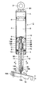
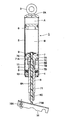
図1および図2は本発明の第1の実施の形態を示している。図1において、第1の実施の形態によるガススプリング装置1は、椅子の背もたれ(図示せず)を弾性的に支持すると共に、背もたれの角度を調整することができる。ガススプリング装置1は、後述するシリンダ2、ピストン部7、ピストンロッド部8、連通路9、プッシュロッド部12を含んで構成されている。
1 and 2 show a first embodiment of the present invention. In FIG. 1, the gas spring device 1 according to the first embodiment can elastically support a chair back (not shown) and adjust the angle of the back. The gas spring device 1 includes a cylinder 2, a piston portion 7, a piston rod portion 8, a communication passage 9, and a push rod portion 12 which will be described later.
シリンダ2は、ガススプリング装置1の外殻をなす円筒体として形成されている。シリンダ2は、その上端がキャップ2Aによって気液密に閉塞されている。このキャップ2Aには、シリンダ2を一の固定部(図示せず)に取付けるための取付アイ3が取付けられている。
The cylinder 2 is formed as a cylindrical body that forms the outer shell of the gas spring device 1. The upper end of the cylinder 2 is gas-liquid tightly closed by the cap 2A. An attachment eye 3 for attaching the cylinder 2 to one fixed portion (not shown) is attached to the cap 2A.
一方、シリンダ2の下端側には、ロッドガイド4がかしめ固定されている。このロッドガイド4は、ピストンロッド部8を摺動可能に支持するもので、その上側位置には、ピストンロッド部8との間を液密にシールするシール部材5が設けられている。
On the other hand, a rod guide 4 is fixed by caulking to the lower end side of the cylinder 2. This rod guide 4 supports the piston rod part 8 so that sliding is possible, The seal member 5 which seals between the piston rod parts 8 fluid-tightly is provided in the upper position.
フリーピストン6は、シリンダ2の上側寄りに位置して該シリンダ2内に摺動自在に挿嵌されている。フリーピストン6は、キャップ2Aとの間にガス室Aを画成し、該ガス室A内には、加圧ガスが封入されている。また、フリーピストン6の下側には、シール部材5との間に作動油が封入されている。
The free piston 6 is located on the upper side of the cylinder 2 and is slidably inserted into the cylinder 2. The free piston 6 defines a gas chamber A between itself and the cap 2 </ b> A, and pressurized gas is sealed in the gas chamber A. In addition, hydraulic oil is sealed between the free piston 6 and the seal member 5.
ピストン部7は、シリンダ2内に設けられている。ピストン部7は、例えば、金属材料に切削加工等を施すことにより段付円筒状に形成されている。具体的には、ピストン部7は、シリンダ2内に軸方向に摺動可能に挿入された厚肉な円筒状の隔壁部7Aと、該隔壁部7Aの中央から下向きに延びた筒状の軸部7Bとを含んで構成されている。隔壁部7Aは、シリンダ2内を、フリーピストン6との間の上側油室Bと、シール部材5との間の下側油室Cとの2室に画成している。
The piston part 7 is provided in the cylinder 2. The piston portion 7 is formed in a stepped cylindrical shape by, for example, cutting a metal material. Specifically, the piston portion 7 includes a thick cylindrical partition wall portion 7A inserted in the cylinder 2 so as to be slidable in the axial direction, and a cylindrical shaft extending downward from the center of the partition wall portion 7A. Part 7B. The partition wall portion 7 </ b> A defines the inside of the cylinder 2 into two chambers: an upper oil chamber B between the free piston 6 and a lower oil chamber C between the seal member 5.
一方、隔壁部7Aの軸中心には、軸部7Bに亘って軸方向に延びた小径孔7Cと、該小径孔7Cの下端を拡径して軸方向に延びた大径孔7Dとが設けられている。さらに、ピストン部7には、小径孔7Cと下側油室Cとを連通する通路部7Eが形成されている。この通路部7Eは、ピストン部7の内径側の一端が小径孔7Cの上側部位に開口し、外径側の他端が軸部7Bの外周面に開口している。ピストン部7の小径孔7Cは、後述するプッシュロッド部12の弁部材13によって開閉される弁座部を形成している。しかも、小径孔7Cは、後述の挿通孔10を構成し、小径孔7Cと通路部7Eとは、後述の連通路9を構成している。
On the other hand, a small-diameter hole 7C extending in the axial direction across the shaft portion 7B and a large-diameter hole 7D extending in the axial direction by expanding the lower end of the small-diameter hole 7C are provided at the axial center of the partition wall portion 7A. It has been. Further, a passage portion 7E that connects the small diameter hole 7C and the lower oil chamber C is formed in the piston portion 7. In the passage portion 7E, one end on the inner diameter side of the piston portion 7 opens at an upper portion of the small diameter hole 7C, and the other end on the outer diameter side opens on the outer peripheral surface of the shaft portion 7B. The small-diameter hole 7C of the piston portion 7 forms a valve seat portion that is opened and closed by a valve member 13 of the push rod portion 12 described later. In addition, the small diameter hole 7C constitutes an insertion hole 10 described later, and the small diameter hole 7C and the passage portion 7E constitute a communication path 9 described later.
ピストンロッド部8は、シリンダ2の軸方向に延びる中空な棒状体として形成されている。ピストンロッド部8は、例えば、金属材料に切削加工等を施すことにより小径で長尺な段付円筒体として形成されている。ピストンロッド部8は、上端側がシリンダ2内でピストン部7の大径孔7Dにかしめ固定されることにより、ピストン部7と一体的に構成されている。一方、ピストンロッド部8の下端側は、シール部材5、ロッドガイド4を介してシリンダ2の外部に延出されている。
The piston rod portion 8 is formed as a hollow rod-like body extending in the axial direction of the cylinder 2. The piston rod portion 8 is formed, for example, as a stepped cylindrical body having a small diameter and a long diameter by cutting a metal material. The piston rod portion 8 is configured integrally with the piston portion 7 by caulking and fixing the upper end side to the large-diameter hole 7D of the piston portion 7 in the cylinder 2. On the other hand, the lower end side of the piston rod portion 8 extends to the outside of the cylinder 2 via the seal member 5 and the rod guide 4.
ピストンロッド部8には、軸中心に位置してロッド孔8Aが形成されている。また、ピストンロッド部8には、ロッド孔8Aの上端部に位置して後述の軸受11等を収容するための拡径収容部8Bが形成されている。一方、ピストンロッド部8の下端側には、当該ピストンロッド部8を他の固定部(図示せず)に取付けるためのねじ部8Cが形成されている。
The piston rod portion 8 is formed with a rod hole 8A located at the center of the axis. Further, the piston rod portion 8 is formed with an enlarged diameter accommodating portion 8B that is located at the upper end portion of the rod hole 8A and accommodates a later-described bearing 11 and the like. On the other hand, on the lower end side of the piston rod portion 8, a screw portion 8C for attaching the piston rod portion 8 to another fixing portion (not shown) is formed.
連通路9は、シリンダ2内に形成された上側油室Bと下側油室Cとを連通するものである。この連通路9は、ピストン部7の小径孔7Cの上側部分と通路部7Eとによって形成されている。
The communication passage 9 communicates the upper oil chamber B and the lower oil chamber C formed in the cylinder 2. The communication passage 9 is formed by the upper portion of the small diameter hole 7C of the piston portion 7 and the passage portion 7E.
挿通孔10は、ピストン部7とピストンロッド部8とに亘り軸方向に貫通して設けられている。この挿通孔10は、ピストン部7の小径孔7Cとピストンロッド部8のロッド孔8Aとにより構成されている。挿通孔10には、後述のプッシュロッド部12が軸方向に移動可能に挿通されている。
The insertion hole 10 is provided so as to penetrate the piston portion 7 and the piston rod portion 8 in the axial direction. The insertion hole 10 is constituted by a small diameter hole 7 </ b> C of the piston portion 7 and a rod hole 8 </ b> A of the piston rod portion 8. A push rod portion 12 described later is inserted into the insertion hole 10 so as to be movable in the axial direction.
軸受11は、ピストン部7の小径孔7C内に挿嵌されている。この軸受11は、自己潤滑性を有する材料によって円筒状に形成された滑り軸受として構成されている。軸受11は、プッシュロッド部12を構成する弁部材13の下側部分を軸方向に移動可能に支持している。
The bearing 11 is inserted into the small diameter hole 7 </ b> C of the piston portion 7. The bearing 11 is configured as a sliding bearing formed in a cylindrical shape from a material having self-lubricating properties. The bearing 11 supports the lower part of the valve member 13 constituting the push rod portion 12 so as to be movable in the axial direction.
次に、本発明の特徴部分となる第1の実施の形態によるプッシュロッド部12の構成について説明する。
Next, the configuration of the push rod portion 12 according to the first embodiment, which is a characteristic part of the present invention, will be described.
プッシュロッド部12は、外部から操作されることにより、上側油室Bと下側油室Cとの間で連通路9を連通(開)または遮断(閉)させるものである。プッシュロッド部12は、後述の弁部材13、ロッド部材14およびキャップ部材15によって構成されている。
The push rod portion 12 is operated from the outside to communicate (open) or block (close) the communication passage 9 between the upper oil chamber B and the lower oil chamber C. The push rod portion 12 includes a valve member 13, a rod member 14, and a cap member 15 which will be described later.
弁部材13は、ピストン部7の小径孔7Cとピストンロッド部8のロッド孔8A(拡径収容部8B)とに亘って配設されている。この弁部材13は、後述のロッド部材14と一緒にロッド本体を構成すると共に、弁部を構成している。弁部材13は、金属製の段付棒状体として形成され、ピストン部7およびピストンロッド部8の軸中心位置に軸方向に移動可能に挿嵌されている。
The valve member 13 is disposed across the small diameter hole 7C of the piston portion 7 and the rod hole 8A (expanded diameter accommodating portion 8B) of the piston rod portion 8. The valve member 13 constitutes a rod body together with a rod member 14 to be described later, and constitutes a valve portion. The valve member 13 is formed as a metal stepped rod-like body, and is inserted into the axial center positions of the piston portion 7 and the piston rod portion 8 so as to be movable in the axial direction.
弁部材13の上側寄り位置には、通路部7Eと対面して縮径部13Aが設けられている。この縮径部13Aは、当該縮径部13Aよりも上側および下側に位置する弁部材13の外周面がピストン部7の小径孔7Cに対して液密に摺接することにより、小径孔7Cとの間に環状通路13Bを形成することができる。ここで、弁部材13は、上端面が上側油室B内の圧力を受承しており、大気圧を受承した下端面との圧力差によって矢示a方向(下向き)に付勢されている。
A reduced diameter portion 13A is provided at a position near the upper side of the valve member 13 so as to face the passage portion 7E. The reduced diameter portion 13A is formed in such a manner that the outer peripheral surface of the valve member 13 located above and below the reduced diameter portion 13A is in fluid-tight sliding contact with the small diameter hole 7C of the piston portion 7, thereby An annular passage 13B can be formed between the two. Here, the upper end surface of the valve member 13 receives the pressure in the upper oil chamber B, and is biased in the direction of arrow a (downward) by the pressure difference from the lower end surface that has received the atmospheric pressure. Yes.
また、環状通路13Bは、弁部材13がロッド部材14等と共に矢示b方向(上向き)に所定寸法押動されることにより、上側油室Bに連通する。このように、環状通路13Bによって上側油室Bと下側油室Cとを連通させた状態では、シリンダ2に対してピストン部7を軸方向に自由に移動させることができる。これにより、シリンダ2に対するピストンロッド部8の突出寸法、即ち、背もたれの角度を調整することができる。
Further, the annular passage 13B communicates with the upper oil chamber B by the valve member 13 being pushed together with the rod member 14 and the like in a direction indicated by an arrow b (upward). Thus, in a state where the upper oil chamber B and the lower oil chamber C are communicated with each other by the annular passage 13B, the piston portion 7 can be freely moved in the axial direction with respect to the cylinder 2. Thereby, the protrusion dimension of the piston rod part 8 with respect to the cylinder 2, ie, the angle of the backrest, can be adjusted.
ロッド部材14は、弁部材13と共にロッド本体を構成するもので、該弁部材13と一緒に挿通孔10に軸方向に移動可能に挿通されている。ロッド部材14は、弁部材13と同様に、金属製の段付棒状体として形成されている。ロッド部材14は、ピストン部7側の上端面が弁部材13の下端面と当接している。
The rod member 14 constitutes a rod body together with the valve member 13, and is inserted into the insertion hole 10 together with the valve member 13 so as to be movable in the axial direction. The rod member 14 is formed as a metal stepped rod like the valve member 13. The rod member 14 is in contact with the lower end surface of the valve member 13 at the upper end surface on the piston portion 7 side.
一方、図2に示すように、反ピストン部7側となるロッド部材14の下端部は、段部14Aから下側が縮径され、この部分が小径軸部14Bとなっている。この小径軸部14Bは、後述のキャップ部材15を取付けるための支柱をなし、キャップ部材15の取付穴15Bに圧入される。
On the other hand, as shown in FIG. 2, the lower end of the rod member 14 on the side opposite to the piston 7 is reduced in diameter from the stepped portion 14A, and this portion is a small-diameter shaft portion 14B. The small-diameter shaft portion 14 </ b> B forms a support for attaching a cap member 15 described later, and is press-fitted into the attachment hole 15 </ b> B of the cap member 15.
キャップ部材15は、ロッド部材14の反ピストン部7側となる下端部に設けられている。キャップ部材15は、後述する外部レバー16によって下側から押圧されたときに、プッシュロッド部12の下側部分が横ずれ(径方向に変位)するのを防止するものである。キャップ部材15は、例えば、自己潤滑性を有する黒鉛、4フッ化エチレン(PTFE)、二硫化モリブデン、二硫化タングステン等の樹脂材料によって有底筒状に形成され、ピストンロッド部8から突出した状態でロッド部材14に取付けられている。より具体的には、キャップ部材15は、下端部15Aが凸球面状となる弾丸形状をなしている。
The cap member 15 is provided at the lower end of the rod member 14 on the side opposite to the piston 7. The cap member 15 prevents the lower portion of the push rod portion 12 from being laterally displaced (displaced in the radial direction) when pressed from below by an external lever 16 described later. The cap member 15 is formed in a bottomed cylindrical shape with a resin material such as graphite having self-lubricating properties, such as graphite, tetrafluoroethylene (PTFE), molybdenum disulfide, and tungsten disulfide, and protrudes from the piston rod portion 8. And attached to the rod member 14. More specifically, the cap member 15 has a bullet shape in which the lower end portion 15A has a convex spherical shape.
また、キャップ部材15の外径寸法(直径寸法)は、ロッド部材14の外径寸法とほぼ同じ寸法、好ましくはロッド部材14の外径寸法よりも多少大きな寸法に設定されている。キャップ部材15の外径寸法を、ロッド部材14の外径寸法よりも大きく形成した場合、ロッド孔8Aには、金属製のロッド部材14よりも先に自己潤滑性を有する樹脂材料からなるキャップ部材15を接触させることができる。
Further, the outer diameter dimension (diameter dimension) of the cap member 15 is set to be approximately the same as the outer diameter dimension of the rod member 14, preferably slightly larger than the outer diameter dimension of the rod member 14. When the outer diameter of the cap member 15 is larger than the outer diameter of the rod member 14, the cap hole made of a resin material having self-lubricating property before the metal rod member 14 is formed in the rod hole 8A. 15 can be brought into contact.
キャップ部材15内には、上向きに開口して取付穴15Bが形成されている。この取付穴15Bには、ロッド部材14の小径軸部14Bが圧入される。さらに、キャップ部材15は、下端部15Aを凸球面状としたことにより、外部レバー16に対する当接状態を常に一定にすることができる。
In the cap member 15, a mounting hole 15B is formed by opening upward. The small diameter shaft portion 14B of the rod member 14 is press-fitted into the mounting hole 15B. Furthermore, the cap member 15 can always make the contact state with the external lever 16 constant by making the lower end portion 15A have a convex spherical shape.
なお、図1に示すように、外部レバー16は、その一端部が前述した他の固定部にピン16Aを介して回動可能に取付けられている。従って、外部レバー16は、ピン16Aを支点として他端部を矢示c方向に回動させることにより、プッシュロッド部12を矢示b方向に押動することができる。この状態では、シリンダ2に対するピストンロッド部8の突出寸法(伸縮量)を調整することができる。
In addition, as shown in FIG. 1, the external lever 16 is attached to the other fixed part mentioned above so that rotation is possible via the pin 16A. Therefore, the external lever 16 can push the push rod portion 12 in the direction indicated by the arrow b by rotating the other end portion in the direction indicated by the arrow c with the pin 16A as a fulcrum. In this state, the protruding dimension (expansion / contraction amount) of the piston rod portion 8 relative to the cylinder 2 can be adjusted.
第1の実施の形態によるガススプリング装置1はこのように構成されるが、次に、ガススプリング装置1の作動について説明する。
The gas spring device 1 according to the first embodiment is configured as described above. Next, the operation of the gas spring device 1 will be described.
外部レバー16を矢示c方向に回動操作し、プッシュロッド部12を矢示b方向に移動させる。これにより、プッシュロッド部12は、弁部材13の環状通路13Bが上側油室Bに達することにより、この上側油室Bと下側油室Cとを連通させる。この状態では、上側油室Bと下側油室Cとの間で作動油を自由に行き来させることができるから、ピストン部7は、シリンダ2に対して軸方向の移動が自由になる。従って、シリンダ2を矢示a方向に押動することにより、ピストンロッド部8をシリンダ2内に押込んで縮小させることができる。一方、シリンダ2を矢示b方向に引っ張ることにより、該ピストンロッド部8をシリンダ2から伸長させることができる。
Rotate the external lever 16 in the direction indicated by the arrow c to move the push rod portion 12 in the direction indicated by the arrow b. Accordingly, the push rod portion 12 causes the upper oil chamber B and the lower oil chamber C to communicate with each other when the annular passage 13B of the valve member 13 reaches the upper oil chamber B. In this state, since the hydraulic oil can freely move back and forth between the upper oil chamber B and the lower oil chamber C, the piston portion 7 is free to move in the axial direction with respect to the cylinder 2. Therefore, by pushing the cylinder 2 in the direction of arrow a, the piston rod portion 8 can be pushed into the cylinder 2 and reduced. On the other hand, the piston rod portion 8 can be extended from the cylinder 2 by pulling the cylinder 2 in the direction indicated by the arrow b.
そして、シリンダ2に対するピストンロッド部8の伸長位置を決定したら、外部レバー16によるプッシュロッド部12の押動を解除する。これにより、各油室B,C間を遮断することができ、ピストンロッド部8の位置を固定することができる。
When the extension position of the piston rod portion 8 with respect to the cylinder 2 is determined, the push rod portion 12 is released from being pushed by the external lever 16. Thereby, between each oil chamber B and C can be interrupted | blocked, and the position of the piston rod part 8 can be fixed.
ここで、外部レバー16を回動させてプッシュロッド部12を押動した場合には、プッシュロッド部12に対して外部レバー16が直角に当接せず、直角よりも大きな角度αをもって外部レバー16がプッシュロッド部12の下部に当接する。この角度αは、例えば45度程度となっている。この場合、プッシュロッド部12には、外部レバー16が斜めに当接したことによって横力、即ち、プッシュロッド部12を径方向(矢示d方向)に押す力が作用する。このため、プッシュロッド部12を構成するロッド部材14は、ピストンロッド部8のロッド孔8Aの内周面に押付けられる。これにより、プッシュロッド部12が軸方向に移動するときの摺動抵抗が増大するから、プッシュロッド部12の押動操作性が悪くなる虞がある。
Here, when the external lever 16 is rotated to push the push rod portion 12, the external lever 16 does not contact the push rod portion 12 at a right angle, and the external lever has an angle α larger than the right angle. 16 contacts the lower part of the push rod part 12. This angle α is, for example, about 45 degrees. In this case, a lateral force, that is, a force that pushes the push rod portion 12 in the radial direction (arrow d direction) acts on the push rod portion 12 due to the external lever 16 abutting obliquely. For this reason, the rod member 14 constituting the push rod portion 12 is pressed against the inner peripheral surface of the rod hole 8 </ b> A of the piston rod portion 8. As a result, the sliding resistance when the push rod portion 12 moves in the axial direction increases, so that the push operability of the push rod portion 12 may be deteriorated.
然るに、第1の実施の形態によれば、シリンダ2内に形成された上側油室Bと下側油室Cとを連通する連通路9を開閉する弁部材13を有するプッシュロッド部12のうち、反ピストン部7側の端部となるロッド部材14の下端部は、キャップ部材15とすることにより樹脂材料を用いて形成している。
However, according to the first embodiment, the push rod portion 12 having the valve member 13 that opens and closes the communication passage 9 that connects the upper oil chamber B and the lower oil chamber C formed in the cylinder 2. The lower end portion of the rod member 14 serving as the end portion on the side opposite to the piston 7 is formed by using a resin material by forming a cap member 15.
これにより、キャップ部材15を形成する樹脂材料を、自己潤滑性を有する樹脂材料とすることにより、外部レバー16に対してキャップ部材15を滑らせることができ、プッシュロッド部12に作用する横力で発生する摺動抵抗を抑制することができる。
As a result, by making the resin material forming the cap member 15 a resin material having self-lubricating property, the cap member 15 can be slid with respect to the external lever 16, and the lateral force acting on the push rod portion 12 can be obtained. It is possible to suppress the sliding resistance generated in
この結果、ピストンロッド部8に対するプッシュロッド部12の摺動抵抗が小さくなるから、ピストンロッド部8とプッシュロッド部12との間のかじりを防止でき、プッシュロッド部12を押動するときの操作性を良好にすることができる。
As a result, since the sliding resistance of the push rod portion 12 with respect to the piston rod portion 8 is reduced, it is possible to prevent galling between the piston rod portion 8 and the push rod portion 12, and to operate the push rod portion 12 for pushing. Property can be improved.
また、ピストン部7とピストンロッド部8とには、軸方向に貫通した挿通孔10が設けられている。この上で、プッシュロッド部12は、挿通孔10に軸方向に移動可能に挿通され弁部材13を有するロッド本体と、このロッド本体を構成するロッド部材14の反ピストン部7側の端部に前記ピストンロッド部8から突出した状態で設けられた樹脂材料からなるキャップ部材15とにより構成されている。従って、キャップ部材15が摩耗または損傷した場合には、新しいキャップ部材15に容易に交換することができる。
Further, the piston portion 7 and the piston rod portion 8 are provided with an insertion hole 10 penetrating in the axial direction. On this, the push rod part 12 is inserted into the insertion hole 10 so as to be movable in the axial direction and has a valve body 13 and an end part of the rod member 14 constituting the rod body on the side opposite to the piston part 7. The cap member 15 is made of a resin material provided in a state of protruding from the piston rod portion 8. Therefore, when the cap member 15 is worn or damaged, it can be easily replaced with a new cap member 15.
一方、キャップ部材15は、その取付穴15Bをロッド部材14の小径軸部14Bに圧入によって取付ける構成としている。これにより、簡単な構成をもってキャップ部材15を、ロッド部材14に取付けることができる。
On the other hand, the cap member 15 is configured to attach the attachment hole 15B to the small diameter shaft portion 14B of the rod member 14 by press fitting. Thereby, the cap member 15 can be attached to the rod member 14 with a simple configuration.
また、キャップ部材15には、反ピストン側となる端部としての下端部15Aを凸球面状としているから、外部レバー16に対するキャップ部材15の下端部15Aの当接状態を常に一定にすることができる。これにより、キャップ部材15の取付方向に関する位置決め作業を省略することができるから、取付作業を簡略化することができる。しかも、キャップ部材15は、単体で加工することができるから、凸球面状の加工を容易に行うことができ、低コスト化を図ることができる。
Further, the cap member 15 has a convex spherical surface at the lower end 15A as the end on the side opposite to the piston, so that the contact state of the lower end 15A of the cap member 15 with respect to the external lever 16 can be always constant. it can. Thereby, since the positioning work regarding the mounting direction of the cap member 15 can be omitted, the mounting work can be simplified. In addition, since the cap member 15 can be processed by itself, the processing of the convex spherical surface can be easily performed, and the cost can be reduced.
さらに、キャップ部材15の外径寸法(直径寸法)は、ロッド部材14の外径寸法とほぼ同じ寸法または多少大きな寸法に設定されている。これにより、キャップ部材15をロッド孔8Aに摺接させることができ、プッシュロッド部12を挿通孔10内で円滑に移動させることができる。
Furthermore, the outer diameter dimension (diameter dimension) of the cap member 15 is set to be approximately the same as or slightly larger than the outer diameter dimension of the rod member 14. Thereby, the cap member 15 can be brought into sliding contact with the rod hole 8 </ b> A, and the push rod portion 12 can be smoothly moved in the insertion hole 10.
次に、図3は本発明の第2の実施の形態を示している。本実施の形態の特徴は、ピストンロッド部の内周側であって、プッシュロッド部と摺動する部位には、滑り軸受が配されていることにある。なお、第2の実施の形態では、前述した第1の実施の形態と同一の構成要素に同一の符号を付し、その説明を省略するものとする。
Next, FIG. 3 shows a second embodiment of the present invention. A feature of the present embodiment is that a sliding bearing is arranged on the inner peripheral side of the piston rod portion and in a portion sliding with the push rod portion. In the second embodiment, the same components as those in the first embodiment are denoted by the same reference numerals, and the description thereof is omitted.
図3において、第2の実施の形態によるピストンロッド部21は、前述した第1の実施の形態によるピストンロッド部8とほぼ同様に、金属材料からなる中空な棒状体として形成され、その軸中心に位置してロッド孔21Aと拡径収容部(図示せず)が形成されている。また、ピストンロッド部21の下端側には、外周側にねじ部21Bが形成されている。しかし、第2の実施の形態によるピストンロッド部21は、ロッド孔21Aの下端側を拡径することにより軸受収容部21Cが形成されている点で、第1の実施の形態によるピストンロッド部8と相違している。
In FIG. 3, the piston rod portion 21 according to the second embodiment is formed as a hollow rod-shaped body made of a metal material in substantially the same manner as the piston rod portion 8 according to the first embodiment described above. A rod hole 21A and an enlarged diameter accommodating portion (not shown) are formed. Further, on the lower end side of the piston rod portion 21, a screw portion 21B is formed on the outer peripheral side. However, the piston rod portion 21 according to the second embodiment has the bearing housing portion 21C formed by expanding the lower end side of the rod hole 21A, and therefore the piston rod portion 8 according to the first embodiment. Is different.
第2の実施の形態による滑り軸受22は、ピストンロッド部21の内周側であって、プッシュロッド部12と摺動する部位、即ち、ピストンロッド部21の軸受収容部21Cに、例えば圧入等の手段を用いて挿嵌されている。この滑り軸受22は、例えば自己潤滑性を有する金属材料または樹脂材料から円筒状に形成され、その内周面でキャップ部材15を軸方向に摺動可能に支持している。
The sliding bearing 22 according to the second embodiment is on the inner peripheral side of the piston rod portion 21 and slides with the push rod portion 12, i.e., press-fits into the bearing housing portion 21 </ b> C of the piston rod portion 21. It is inserted using the means. The slide bearing 22 is formed in a cylindrical shape from, for example, a self-lubricating metal material or resin material, and supports the cap member 15 slidably in the axial direction on the inner peripheral surface thereof.
かくして、このように構成された第2の実施の形態においても、前述した第1の実施の形態とほぼ同様の作用効果を得ることができる。特に、第2の実施の形態によれば、ピストンロッド部21の内周側であって、プッシュロッド部12と摺動する部位には、自己潤滑性を有する滑り軸受22を設ける構成としている。これにより、滑り軸受22は、キャップ部材15を軸方向に摺動可能に支持することができ、プッシュロッド部12の動作性をより一層良好にすることができる。
Thus, also in the second embodiment configured as described above, it is possible to obtain substantially the same operational effects as those of the first embodiment described above. In particular, according to the second embodiment, a sliding bearing 22 having self-lubricating properties is provided on the inner peripheral side of the piston rod portion 21 and in a portion that slides with the push rod portion 12. Thereby, the slide bearing 22 can support the cap member 15 so as to be slidable in the axial direction, and the operability of the push rod portion 12 can be further improved.
次に、図4は本発明の第3の実施の形態を示している。本実施の形態の特徴は、ピストンロッド部の内周側であって、プッシュロッド部と摺動する部位には、滑り軸受が配されている。また、キャップ部材は、プッシュロッド部に対し螺合によって取付けられている。なお、第3の実施の形態では、前述した第1の実施の形態と同一の構成要素に同一の符号を付し、その説明を省略するものとする。
Next, FIG. 4 shows a third embodiment of the present invention. The feature of the present embodiment is that the inner side of the piston rod portion is provided with a sliding bearing at a portion that slides with the push rod portion. The cap member is attached to the push rod portion by screwing. Note that in the third embodiment, the same components as those in the first embodiment described above are denoted by the same reference numerals, and description thereof is omitted.
図4において、第3の実施の形態によるピストンロッド部31は、前述した第2の実施の形態によるピストンロッド部21と同様に、ロッド孔31A、拡径収容部(図示せず)、ねじ部31Bおよび軸受収容部31Cを備えている。この軸受収容部31Cには、自己潤滑性を有する金属材料または樹脂材料からなる滑り軸受32が挿嵌されている。
In FIG. 4, the piston rod portion 31 according to the third embodiment is similar to the piston rod portion 21 according to the second embodiment described above, with a rod hole 31 </ b> A, an enlarged diameter accommodating portion (not shown), and a screw portion. 31B and the bearing accommodating part 31C are provided. A sliding bearing 32 made of a metal material or a resin material having a self-lubricating property is inserted into the bearing housing portion 31C.
第3の実施の形態によるロッド部材33は、第1の実施の形態によるロッド部材14とほぼ同様に、ロッド本体の一部をなすもので、金属製の段付棒状体として形成されている。しかし、第3の実施の形態によるロッド部材33は、下端部に段部33Aとねじ軸33Bが形成されている点で、第1の実施の形態によるロッド部材14と相違している。
The rod member 33 according to the third embodiment forms a part of the rod main body and is formed as a metal stepped rod-like body, almost the same as the rod member 14 according to the first embodiment. However, the rod member 33 according to the third embodiment is different from the rod member 14 according to the first embodiment in that a step portion 33A and a screw shaft 33B are formed at the lower end portion.
第3の実施の形態によるキャップ部材34は、第1の実施の形態によるキャップ部材15とほぼ同様に、ロッド部材33の下端部に設けられている。このキャップ部材34は、自己潤滑性を有する樹脂材料によって有底筒状に形成され、下端部34Aが凸球面状に形成されている。さらに、キャップ部材34内には、上向きに開口して取付穴34Bが形成されている。しかし、第3の実施の形態によるキャップ部材34は、取付穴34Bがロッド部材33のねじ軸33Bに螺合するねじ穴として形成されている点で、第1の実施の形態によるキャップ部材15と相違している。
The cap member 34 according to the third embodiment is provided at the lower end of the rod member 33 in substantially the same manner as the cap member 15 according to the first embodiment. The cap member 34 is formed into a bottomed cylindrical shape by a self-lubricating resin material, and the lower end portion 34A is formed in a convex spherical shape. Further, a mounting hole 34B is formed in the cap member 34 so as to open upward. However, the cap member 34 according to the third embodiment is different from the cap member 15 according to the first embodiment in that the mounting hole 34B is formed as a screw hole that engages with the screw shaft 33B of the rod member 33. It is different.
かくして、このように構成された第3の実施の形態においても、前述した第1、第2の実施の形態とほぼ同様の作用効果を得ることができる。特に、第3の実施の形態によれば、ロッド部材33のねじ軸33Bに雌ねじからなる取付穴34Bを螺合することにより、キャップ部材34をロッド部材33に容易に取付けることができる。また、キャップ部材34を容易に交換することができる。
Thus, also in the third embodiment configured as described above, it is possible to obtain substantially the same operational effects as those of the first and second embodiments described above. In particular, according to the third embodiment, the cap member 34 can be easily attached to the rod member 33 by screwing the attachment hole 34 </ b> B made of a female screw into the screw shaft 33 </ b> B of the rod member 33. Further, the cap member 34 can be easily replaced.
次に、図5は本発明の第4の実施の形態を示している。本実施の形態の特徴は、ピストンロッド部の内周側であって、プッシュロッド部と摺動する部位には、滑り軸受が配されている。また、プッシュロッド部は、下端部を縮径することなく、この下端部にキャップ部材を取付ける構成としている。なお、第4の実施の形態では、前述した第1の実施の形態と同一の構成要素に同一の符号を付し、その説明を省略するものとする。
Next, FIG. 5 shows a fourth embodiment of the present invention. The feature of the present embodiment is that the inner side of the piston rod portion is provided with a sliding bearing at a portion that slides with the push rod portion. Further, the push rod portion is configured to attach the cap member to the lower end portion without reducing the diameter of the lower end portion. Note that in the fourth embodiment, the same components as those in the first embodiment described above are denoted by the same reference numerals, and description thereof is omitted.
図5において、第4の実施の形態によるピストンロッド部41は、前述した第2の実施の形態によるピストンロッド部21とほぼ同様に、ロッド孔41A、拡径収容部(図示せず)、ねじ部41Bおよび軸受収容部41Cを備えている。しかし、第4の実施の形態によるピストンロッド部41は、後述の滑り軸受42がキャップ部材44に軸方向で干渉しないように、軸受収容部41Cが奥部に配置されている点で、第2の実施の形態によるピストンロッド部21と相違している。これに伴い、ピストンロッド部41には、ロッド孔41Aよりも大きな直径寸法をもってキャップ挿通孔41Dが形成されている。
In FIG. 5, the piston rod portion 41 according to the fourth embodiment is substantially the same as the piston rod portion 21 according to the second embodiment described above, and includes a rod hole 41 </ b> A, an enlarged diameter accommodating portion (not shown), a screw. A portion 41B and a bearing housing portion 41C are provided. However, the piston rod portion 41 according to the fourth embodiment is different in that the bearing housing portion 41 </ b> C is disposed at the back so that a slide bearing 42 described later does not interfere with the cap member 44 in the axial direction. This is different from the piston rod portion 21 according to the embodiment. Accordingly, a cap insertion hole 41D is formed in the piston rod portion 41 with a larger diameter dimension than the rod hole 41A.
第4の実施の形態による滑り軸受42は、第2の実施の形態による滑り軸受22と同様に、自己潤滑性を有する金属材料または樹脂材料からなり、ピストンロッド部41の軸受収容部41Cに挿嵌されている。
Similar to the sliding bearing 22 according to the second embodiment, the sliding bearing 42 according to the fourth embodiment is made of a self-lubricating metal material or resin material and is inserted into the bearing housing portion 41C of the piston rod portion 41. It is fitted.
第4の実施の形態によるロッド部材43は、第1の実施の形態によるロッド部材14とほぼ同様に、ロッド本体の一部をなすもので、金属製の段付棒状体として形成されている。しかし、第4の実施の形態によるロッド部材33は、下端部に段部と小径軸部とが形成されていない点で、第1の実施の形態によるロッド部材14と相違している。
The rod member 43 according to the fourth embodiment is a part of the rod main body, and is formed as a metal stepped rod-like body, almost the same as the rod member 14 according to the first embodiment. However, the rod member 33 according to the fourth embodiment is different from the rod member 14 according to the first embodiment in that a step portion and a small diameter shaft portion are not formed at the lower end portion.
第4の実施の形態によるキャップ部材44は、第1の実施の形態によるキャップ部材15とほぼ同様に、ロッド部材43の下端部に設けられている。このキャップ部材44は、自己潤滑性を有する樹脂材料によって有底筒状に形成され、下端部44Aが凸球面状に形成されている。また、キャップ部材44内には、上向きに開口して取付穴44Bが形成されている。
The cap member 44 according to the fourth embodiment is provided at the lower end of the rod member 43 in substantially the same manner as the cap member 15 according to the first embodiment. The cap member 44 is formed in a bottomed cylindrical shape by a self-lubricating resin material, and the lower end portion 44A is formed in a convex spherical shape. Further, an attachment hole 44B is formed in the cap member 44 so as to open upward.
しかし、第4の実施の形態によるキャップ部材44は、第1の実施の形態によるキャップ部材15よりも大径に形成されている点で、この第1の実施の形態によるキャップ部材15と相違している。具体的には、キャップ部材44の取付穴44Bの内径寸法が、ロッド部材33が挿嵌される寸法に設定されている。さらに、キャップ部材44は、ピストンロッド部41のキャップ挿通孔41D内に小さな隙間をもって挿入されている。
However, the cap member 44 according to the fourth embodiment is different from the cap member 15 according to the first embodiment in that the cap member 44 is formed to have a larger diameter than the cap member 15 according to the first embodiment. ing. Specifically, the inner diameter dimension of the mounting hole 44B of the cap member 44 is set to a dimension in which the rod member 33 is inserted. Further, the cap member 44 is inserted into the cap insertion hole 41D of the piston rod portion 41 with a small gap.
かくして、このように構成された第4の実施の形態においても、前述した各実施の形態とほぼ同様の作用効果を得ることができる。特に、第4の実施の形態によれば、キャップ部材44を大径に形成したことにより、ロッド部材43の下端部に段付加工を施すことなく、キャップ部材44を取付けることができる。これにより、キャップ部材44を設けるための加工コストを低減することができる。
Thus, also in the fourth embodiment configured as described above, it is possible to obtain substantially the same operational effects as the above-described embodiments. In particular, according to the fourth embodiment, since the cap member 44 is formed to have a large diameter, the cap member 44 can be attached without performing stepping on the lower end portion of the rod member 43. Thereby, the processing cost for providing the cap member 44 can be reduced.
次に、図6は本発明の第5の実施の形態を示している。本実施の形態の特徴は、ピストンロッド部の内周側であって、プッシュロッド部と摺動する部位には、滑り軸受が配されている。また、キャップ部材は、プッシュロッド部に設けたピンに係合することで取付けられている。なお、第5の実施の形態では、前述した第1の実施の形態と同一の構成要素に同一の符号を付し、その説明を省略するものとする。
Next, FIG. 6 shows a fifth embodiment of the present invention. The feature of the present embodiment is that the inner side of the piston rod portion is provided with a sliding bearing at a portion that slides with the push rod portion. Moreover, the cap member is attached by engaging with a pin provided on the push rod portion. Note that in the fifth embodiment, the same components as those in the first embodiment described above are denoted by the same reference numerals, and description thereof is omitted.
図6において、第5の実施の形態によるピストンロッド部51は、前述した第2の実施の形態によるピストンロッド部21と同様に、ロッド孔51A、拡径収容部(図示せず)、ねじ部51Bおよび軸受収容部51Cを備えている。この軸受収容部51Cには、自己潤滑性を有する金属材料または樹脂材料からなる滑り軸受52が挿嵌されている。
In FIG. 6, the piston rod portion 51 according to the fifth embodiment is similar to the piston rod portion 21 according to the second embodiment described above, with a rod hole 51 </ b> A, an enlarged diameter accommodating portion (not shown), and a screw portion. 51B and the bearing accommodating part 51C are provided. A sliding bearing 52 made of a metal material or a resin material having a self-lubricating property is inserted into the bearing housing portion 51C.
第5の実施の形態によるロッド部材53は、第1の実施の形態によるロッド部材14とほぼ同様に、ロッド本体の一部をなすもので、金属製の段付棒状体として形成されている。また、ロッド部材53の下端部には、段部53Aと小径軸部53Bとが設けられている。しかし、第5の実施の形態によるロッド部材53は、小径軸部53Bに径方向の外側に突出して係合ピン53Cが設けられている点で、第1の実施の形態によるロッド部材14と相違している。
The rod member 53 according to the fifth embodiment is a part of the rod main body and is formed as a metal stepped rod-like body, almost the same as the rod member 14 according to the first embodiment. Further, a step portion 53A and a small-diameter shaft portion 53B are provided at the lower end portion of the rod member 53. However, the rod member 53 according to the fifth embodiment is different from the rod member 14 according to the first embodiment in that an engagement pin 53C is provided on the small diameter shaft portion 53B so as to protrude outward in the radial direction. is doing.
第5の実施の形態によるキャップ部材54は、第1の実施の形態によるキャップ部材15とほぼ同様に、ロッド部材53の下端部に設けられている。このキャップ部材54は、自己潤滑性を有する樹脂材料によって有底筒状に形成され、下端部54Aが凸球面状に形成されている。さらに、キャップ部材54内には、上向きに開口して取付穴54Bが形成されている。しかし、第5の実施の形態によるキャップ部材54は、取付穴54Bの内周面にロッド部材53の係合ピン53Cに係合する係合溝54Cが形成されている点で、第1の実施の形態によるキャップ部材15と相違している。
The cap member 54 according to the fifth embodiment is provided at the lower end of the rod member 53 in substantially the same manner as the cap member 15 according to the first embodiment. The cap member 54 is formed in a bottomed cylindrical shape by a self-lubricating resin material, and the lower end portion 54A is formed in a convex spherical shape. Further, a mounting hole 54B is formed in the cap member 54 so as to open upward. However, the cap member 54 according to the fifth embodiment is the first embodiment in that an engagement groove 54C that engages with the engagement pin 53C of the rod member 53 is formed on the inner peripheral surface of the mounting hole 54B. This is different from the cap member 15 of the form.
ここで、キャップ部材54の係合溝54Cは、取付穴54Bの開口端から軸方向に延びた後に、周方向に屈曲した略L字状の凹溝として形成されている。従って、キャップ部材54は、ロッド部材53の係合ピン53Cが係合溝54Cに沿って進入するように、取付穴54Bに小径軸部53Bを挿入させた後、キャップ部材54をロッド部材53に対して回転させる。これにより、キャップ部材54の係合溝54Cとロッド部材53の係合ピン53Cとを係合させることができ、キャップ部材54をロッド部材53に抜止め状態で取付けることができる。
Here, the engaging groove 54C of the cap member 54 is formed as a substantially L-shaped concave groove that extends in the axial direction from the opening end of the mounting hole 54B and then bends in the circumferential direction. Therefore, the cap member 54 is inserted into the mounting hole 54B so that the engaging pin 53C of the rod member 53 enters along the engaging groove 54C, and then the cap member 54 is attached to the rod member 53. Rotate against. Thereby, the engagement groove 54 </ b> C of the cap member 54 and the engagement pin 53 </ b> C of the rod member 53 can be engaged, and the cap member 54 can be attached to the rod member 53 in a retaining state.
かくして、このように構成された第5の実施の形態においても、前述した各実施の形態とほぼ同様の作用効果を得ることができる。特に、第5の実施の形態によれば、キャップ部材54の係合溝54Cに、ロッド部材53の係合ピン53Cを係合させることにより、キャップ部材54をロッド部材53に容易に取付けることができる。また、キャップ部材54を容易に交換することができる。
Thus, also in the fifth embodiment configured as described above, it is possible to obtain substantially the same operational effects as those of the above-described embodiments. In particular, according to the fifth embodiment, the cap member 54 can be easily attached to the rod member 53 by engaging the engagement pin 53C of the rod member 53 with the engagement groove 54C of the cap member 54. it can. Further, the cap member 54 can be easily replaced.
次に、図7は本発明の第6の実施の形態を示している。本実施の形態の特徴は、プッシュロッド部のロッド部材を樹脂材料によって形成したことにある。なお、第6の実施の形態では、前述した第1の実施の形態と同一の構成要素に同一の符号を付し、その説明を省略するものとする。
Next, FIG. 7 shows a sixth embodiment of the present invention. The feature of this embodiment is that the rod member of the push rod portion is formed of a resin material. Note that in the sixth embodiment, the same components as those in the first embodiment described above are denoted by the same reference numerals, and descriptions thereof are omitted.
図7において、第6の実施の形態によるプッシュロッド部61は、第1の実施の形態で述べた弁部材13と後述のロッド部材62とにより構成されている。
In FIG. 7, the push rod portion 61 according to the sixth embodiment is constituted by the valve member 13 described in the first embodiment and a rod member 62 described later.
第6の実施の形態によるロッド部材62は、例えば自己潤滑性を有する樹脂材料から棒状体として形成されている。ロッド部材62は、ピストンロッド部8のロッド孔8A内に軸方向に移動可能に配されている。ロッド部材62の上端面は、弁部材13の下端面と当接している。一方、ロッド部材62の下端側は、ロッド孔8Aから突出し、その下端部62Aが凸球面状に形成されている。この下端部62Aは、外部レバー16に当接されている。
The rod member 62 according to the sixth embodiment is formed as a rod-shaped body from a resin material having self-lubricating properties, for example. The rod member 62 is disposed in the rod hole 8A of the piston rod portion 8 so as to be movable in the axial direction. The upper end surface of the rod member 62 is in contact with the lower end surface of the valve member 13. On the other hand, the lower end side of the rod member 62 protrudes from the rod hole 8A, and the lower end portion 62A is formed in a convex spherical shape. The lower end 62A is in contact with the external lever 16.
かくして、このように構成された第6の実施の形態においても、前述した各実施の形態とほぼ同様の作用効果を得ることができる。特に、第6の実施の形態によれば、自己潤滑性を有する樹脂材料からなるロッド部材62は、ピストンロッド部8に対して円滑に摺動させることができ、プッシュロッド部61を良好に動作させることができる。また、部品点数を削減することができる。
Thus, in the sixth embodiment configured as described above, it is possible to obtain substantially the same operational effects as those of the above-described embodiments. In particular, according to the sixth embodiment, the rod member 62 made of a self-lubricating resin material can be smoothly slid with respect to the piston rod portion 8, and the push rod portion 61 operates well. Can be made. In addition, the number of parts can be reduced.
次に、図8は本発明の第7の実施の形態を示している。本実施の形態の特徴は、プッシュロッド部は、反ピストン部側の端部からピストン部側の端部までの全長が樹脂材料によって形成されていることにある。なお、第7の実施の形態では、前述した第1の実施の形態と同一の構成要素に同一の符号を付し、その説明を省略するものとする。
Next, FIG. 8 shows a seventh embodiment of the present invention. The feature of this embodiment is that the push rod portion is formed of a resin material over the entire length from the end on the anti-piston portion side to the end on the piston portion side. Note that in the seventh embodiment, the same components as those in the first embodiment described above are denoted by the same reference numerals, and descriptions thereof are omitted.
図8において、第7の実施の形態によるプッシュロッド部71は、反ピストン部7側となる上側の端部からピストン部7側となる下側の端部までの全長、即ち、挿通孔10を貫通した全長に亘って単一部材として形成されている。プッシュロッド部71は、例えば自己潤滑性を有する樹脂材料から段付棒状体として形成されている。プッシュロッド部71は、上側部位がピストン部7の小径孔7C内で、連通路9を開閉する弁部71Aとなっている。一方、プッシュロッド部71の下端部71Bは、挿通孔10から突出して凸球面状に形成され、外部レバー16に当接している。
In FIG. 8, the push rod portion 71 according to the seventh embodiment has a total length from the upper end portion on the anti-piston portion 7 side to the lower end portion on the piston portion 7 side, that is, the insertion hole 10. It is formed as a single member over the entire length of penetration. The push rod portion 71 is formed as a stepped rod-shaped body from a resin material having self-lubricating properties, for example. The push rod portion 71 is a valve portion 71 </ b> A that opens and closes the communication passage 9 in the small diameter hole 7 </ b> C of the piston portion 7 at the upper side portion. On the other hand, the lower end portion 71 </ b> B of the push rod portion 71 protrudes from the insertion hole 10, is formed in a convex spherical shape, and is in contact with the external lever 16.
かくして、このように構成された第7の実施の形態においても、前述した各実施の形態とほぼ同様の作用効果を得ることができる。特に、第7の実施の形態によれば、プッシュロッド部71は、反ピストン部7側の端部からピストン部7側の端部までの全長が樹脂材料によって形成されている。従って、プッシュロッド部71は、ピストンロッド部8に対して円滑に摺動させることができ、動作性を良好にすることができる。また、部品点数をさらに削減することができる。
Thus, also in the seventh embodiment configured as described above, it is possible to obtain substantially the same operational effects as the above-described embodiments. In particular, according to the seventh embodiment, the push rod portion 71 has the entire length from the end portion on the anti-piston portion 7 side to the end portion on the piston portion 7 side made of a resin material. Therefore, the push rod portion 71 can be smoothly slid with respect to the piston rod portion 8, and the operability can be improved. In addition, the number of parts can be further reduced.
次に、図9は本発明の第8の実施の形態を示している。本実施の形態の特徴は、ピストン部とピストンロッド部とを単一部材として形成すると共に、プッシュロッド部を全長に亘って樹脂材料によって形成したことにある。なお、第8の実施の形態では、前述した第1の実施の形態と同一の構成要素に同一の符号を付し、その説明を省略するものとする。
Next, FIG. 9 shows an eighth embodiment of the present invention. A feature of the present embodiment is that the piston portion and the piston rod portion are formed as a single member, and the push rod portion is formed of a resin material over the entire length. In the eighth embodiment, the same components as those in the first embodiment described above are denoted by the same reference numerals, and description thereof is omitted.
図9において、第8の実施の形態によるピストン-ロッド部材81は、ピストン部82とピストンロッド部83とによって形成されている。このピストン-ロッド部材81は、ピストン部82とピストンロッド部83とを、例えば焼結加工を用いた焼結金属体として一体形成している。
In FIG. 9, the piston-rod member 81 according to the eighth embodiment is formed of a piston portion 82 and a piston rod portion 83. In the piston-rod member 81, a piston portion 82 and a piston rod portion 83 are integrally formed as a sintered metal body using, for example, a sintering process.
ピストン-ロッド部材81には、ピストン部82とピストンロッド部83とに亘って挿通孔84が設けられている。ピストン部82には、挿通孔84に連通するように通路部82Aが形成されている。また、ピストンロッド部83の下側部位には、ピストンロッド部83を他の固定部(図示せず)に取付けるためのねじ部83Aが形成されている。
The piston-rod member 81 is provided with an insertion hole 84 extending between the piston portion 82 and the piston rod portion 83. A passage portion 82 </ b> A is formed in the piston portion 82 so as to communicate with the insertion hole 84. Further, a screw portion 83A for attaching the piston rod portion 83 to another fixing portion (not shown) is formed in the lower portion of the piston rod portion 83.
第8の実施の形態によるプッシュロッド部85は、反ピストン部82側となる上側の端部からピストン部82側となる下側の端部までの全長、即ち、挿通孔84を貫通した全長に亘って単一部材として形成されている。プッシュロッド部85は、例えば自己潤滑性を有する樹脂材料から段付棒状体として形成されている。プッシュロッド部85は、上側部位が弁部85Aとなっている。一方、プッシュロッド部85の下端部85Bは、挿通孔84から突出して凸球面状に形成され、外部レバー16に当接している。
The push rod portion 85 according to the eighth embodiment has a full length from the upper end portion on the anti-piston portion 82 side to the lower end portion on the piston portion 82 side, that is, the full length penetrating the insertion hole 84. It is formed as a single member. The push rod portion 85 is formed as a stepped rod-shaped body from a resin material having self-lubricating properties, for example. The push rod portion 85 has a valve portion 85A on the upper side portion. On the other hand, the lower end portion 85 </ b> B of the push rod portion 85 protrudes from the insertion hole 84 and is formed in a convex spherical shape, and is in contact with the external lever 16.
かくして、このように構成された第8の実施の形態においても、前述した各実施の形態とほぼ同様の作用効果を得ることができる。特に、第8の実施の形態によれば、ピストン部82とピストンロッド部83とを、焼結加工を用いて1個のピストン-ロッド部材81として形成している。これにより、部品点数を削減して組立作業性等を向上することができる。しかも、一体形成されたピストン-ロッド部材81は、軸方向寸法を短縮することができるから、ガススプリング装置1の全長を短くすることができる。
Thus, also in the eighth embodiment configured as described above, it is possible to obtain substantially the same operational effects as those of the above-described embodiments. In particular, according to the eighth embodiment, the piston portion 82 and the piston rod portion 83 are formed as one piston-rod member 81 by using a sintering process. Thereby, the number of parts can be reduced and the assembly workability can be improved. In addition, since the piston-rod member 81 formed integrally can shorten the axial dimension, the overall length of the gas spring device 1 can be shortened.
また、プッシュロッド部85は、反ピストン部82側の端部からピストン部82側の端部までの全長が樹脂材料によって形成されている。従って、プッシュロッド部85は、挿通孔84内で円滑に摺動させることができ、動作性を良好にすることができる。また、部品点数を削減することができる。
Further, the push rod portion 85 is formed of a resin material over the entire length from the end on the anti-piston portion 82 side to the end on the piston portion 82 side. Therefore, the push rod portion 85 can be smoothly slid in the insertion hole 84, and the operability can be improved. In addition, the number of parts can be reduced.
なお、各実施の形態では、ガススプリング装置1を椅子の背もたれの角度を調整する背角調整機構に適用した場合を例に挙げて説明した。しかし、本発明はこれに限らず、例えば、ガススプリング装置1を椅子の座部の高さを調整する高さ調整機構に適用する構成としてもよい。また、ガススプリング装置1は、椅子以外にもベッド等に適用することもできる。
In each embodiment, the case where the gas spring device 1 is applied to a back angle adjustment mechanism that adjusts the angle of the backrest of the chair has been described as an example. However, this invention is not restricted to this, For example, it is good also as a structure which applies the gas spring apparatus 1 to the height adjustment mechanism which adjusts the height of the seat part of a chair. Further, the gas spring device 1 can be applied to a bed or the like other than a chair.
以上説明した実施形態に基づくガススプリング装置として、例えば、以下に述べる態様のものが考えられる。
As the gas spring device based on the embodiment described above, for example, the following modes can be considered.
ガススプリング装置の第1の態様としては、内部に加圧ガスが封入されたシリンダと、該シリンダ内に摺動可能に挿入されて当該シリンダ内を2室に画成するピストン部と、一端が前記ピストン部に連結され、他端が前記シリンダの外部に延出されたピストンロッド部と、前記シリンダ内に形成された前記2室を連通する連通路と、該連通路を開閉する弁部を有するプッシュロッド部とを備え、前記プッシュロッド部を外部から操作して前記連通路を開放して前記ピストンロッド部の前記シリンダに対する軸方向長さを調整可能としたガススプリング装置において、前記プッシュロッド部のうち、少なくとも反ピストン部側の端部は、樹脂材料を用いて形成されている。
As a first aspect of the gas spring device, a cylinder in which pressurized gas is enclosed, a piston portion slidably inserted into the cylinder and defining the inside of the cylinder in two chambers, and one end thereof A piston rod portion connected to the piston portion, the other end extending to the outside of the cylinder, a communication passage communicating the two chambers formed in the cylinder, and a valve portion for opening and closing the communication passage. A push rod portion having a push rod portion, wherein the push rod portion is operated from the outside to open the communication path and adjust an axial length of the piston rod portion with respect to the cylinder. Of the portions, at least the end portion on the side opposite to the piston portion is formed using a resin material.
第2の態様としては、第1の態様において、前記ピストンロッド部の内周側であって、前記プッシュロッド部と摺動する部位には、滑り軸受が配されている。
As a second aspect, in the first aspect, a sliding bearing is disposed on the inner peripheral side of the piston rod portion and in a portion sliding with the push rod portion.
第3の態様としては、第1の態様において、前記ピストン部と前記ピストンロッド部とには、軸方向に貫通した挿通孔が設けられており、前記プッシュロッド部は、前記挿通孔に軸方向に移動可能に挿通され前記弁部を有するロッド本体と、前記ロッド本体の前記反ピストン部側の端部に前記ピストンロッド部から突出した状態で設けられた樹脂材料からなるキャップ部材とにより構成されている。
As a third aspect, in the first aspect, the piston part and the piston rod part are provided with an insertion hole penetrating in the axial direction, and the push rod part is axially formed in the insertion hole. And a cap body made of a resin material provided in a state of protruding from the piston rod section at the end of the rod body on the side opposite to the piston section. ing.
第4の態様としては、第1の態様において、前記プッシュロッド部は、前記反ピストン部側の端部からピストン部側の端部までの全長が樹脂材料によって形成されている。
As a fourth aspect, in the first aspect, the push rod portion is formed of a resin material over the entire length from the end portion on the anti-piston portion side to the end portion on the piston portion side.
第5の態様としては、第3の態様において、前記キャップ部材の端部は、凸球面状である。
As a fifth aspect, in the third aspect, the end of the cap member has a convex spherical shape.
第6の態様としては、第3乃至第4の態様において、前記キャップ部材の外径寸法は、前記ロッド本体の外径寸法と同じまたは多少大きい寸法に設定される。
As a sixth aspect, in the third to fourth aspects, the outer diameter of the cap member is set to be the same as or slightly larger than the outer diameter of the rod body.
第7の態様としては、第3の態様において、前記ピストン部と前記ピストンロッド部とを単一部材によって形成されている。
As a seventh aspect, in the third aspect, the piston part and the piston rod part are formed by a single member.
以上、本発明の幾つかの実施形態のみを説明したが、本発明の新規の教示や利点から実質的に外れることなく例示の実施形態に、多様な変更または改良を加えることが可能であることが当業者には容易に理解できるであろう。従って、その様な変更または改良を加えた形態も本発明の技術的範囲に含むことを意図する。上記実施形態を任意に組み合わせても良い。
Although only a few embodiments of the present invention have been described above, various modifications or improvements can be made to the illustrated embodiments without substantially departing from the novel teachings and advantages of the present invention. Will be easily understood by those skilled in the art. Therefore, it is intended that the embodiment added with such changes or improvements is also included in the technical scope of the present invention. You may combine the said embodiment arbitrarily.
本願は、2016年5月27日付出願の日本国特許出願第2016-106183号に基づく優先権を主張する。2016年5月27日付出願の日本国特許出願第2016-106183号の明細書、特許請求の範囲、図面、及び要約書を含む全開示内容は、参照により本願に全体として組み込まれる。
This application claims priority based on Japanese Patent Application No. 2016-106183 filed on May 27, 2016. The entire disclosure including the specification, claims, drawings, and abstract of Japanese Patent Application No. 2016-106183 filed on May 27, 2016 is incorporated herein by reference in its entirety.
1 ガススプリング装置 2 シリンダ 7,82 ピストン部 8,21,31,41,51,83 ピストンロッド部 9 連通路 10,84 挿通孔 12,61,71,85 プッシュロッド部 13 弁部材(弁部、ロッド本体) 14,33,43,53,62 ロッド部材(ロッド本体) 15,34,44,54 キャップ部材 16 外部レバー 22,32,42,52 滑り軸受 71A,85A 弁部 B 上側油室 C 下側油室
1 Gas spring device 2 Cylinder 7, 82 Piston part 8, 21, 31, 41, 51, 83 Piston rod part 9 Communication path 10, 84 Insertion hole 12, 61, 71, 85 Push rod part 13 Valve member (valve part, Rod body) 14, 33, 43, 53, 62 Rod member (rod body) 15, 34, 44, 54 Cap member 16 External lever 22, 32, 42, 52 Slide bearing 71A, 85A Valve part B Upper oil chamber C Below Side oil chamber
Claims (7)
- ガススプリング装置であって、該ガススプリング装置は、
シリンダの内部に加圧ガスが封入された前記シリンダと、
該シリンダ内に摺動可能に挿入されて当該シリンダ内を2室に画成するピストン部と、
一端が前記ピストン部に連結され、他端が前記シリンダの外部に延出されたピストンロッド部と、
前記シリンダ内に形成された前記2室を連通する連通路と、
該連通路を開閉する弁部を有するプッシュロッド部とを備え、
前記プッシュロッド部を外部から操作することにより、前記連通路を開放して前記ピストンロッド部の前記シリンダに対する軸方向長さを調整可能とし、
前記プッシュロッド部のうち、少なくとも反ピストン部側の端部は、樹脂材料を用いて形成されていることを特徴とするガススプリング装置。 A gas spring device, the gas spring device comprising:
The cylinder in which pressurized gas is sealed inside the cylinder;
A piston part slidably inserted into the cylinder and defining the inside of the cylinder into two chambers;
A piston rod part having one end connected to the piston part and the other end extending to the outside of the cylinder;
A communication passage communicating the two chambers formed in the cylinder;
A push rod part having a valve part for opening and closing the communication path,
By operating the push rod part from the outside, it is possible to adjust the axial length of the piston rod part with respect to the cylinder by opening the communication path,
Among the push rod parts, at least the end part on the side opposite to the piston part is formed using a resin material. - 請求項1に記載のガススプリング装置において、
前記ピストンロッド部の内周側であって、前記プッシュロッド部と摺動する部位には、滑り軸受が配されていることを特徴とするガススプリング装置。 The gas spring device according to claim 1, wherein
A gas spring device characterized in that a sliding bearing is disposed on a portion that slides with the push rod portion on the inner peripheral side of the piston rod portion. - 請求項1または2に記載のガススプリング装置において、
前記ピストン部と前記ピストンロッド部とには、該ピストン部と該ピストンロッド部の軸方向に貫通した挿通孔が設けられており、
前記プッシュロッド部は、
前記挿通孔に軸方向に移動可能に挿通され前記弁部を有するロッド本体と、
前記ロッド本体の前記反ピストン部側の端部に前記ピストンロッド部から突出した状態で設けられた樹脂材料からなるキャップ部材とを備えていることを特徴とするガススプリング装置。 The gas spring device according to claim 1 or 2,
The piston part and the piston rod part are provided with an insertion hole penetrating in the axial direction of the piston part and the piston rod part,
The push rod part is
A rod body inserted through the insertion hole so as to be movable in the axial direction and having the valve portion;
A gas spring device comprising: a cap member made of a resin material provided in a state of protruding from the piston rod portion at an end of the rod body on the side opposite to the piston portion. - 請求項1または2に記載のガススプリング装置において、
前記プッシュロッド部は、前記反ピストン部側の端部からピストン部側の端部までの全長が樹脂材料によって形成されていることを特徴とするガススプリング装置。 The gas spring device according to claim 1 or 2,
A gas spring device characterized in that the push rod part is formed of a resin material over the entire length from the end part on the side opposite to the piston part to the end part on the piston part side. - 請求項3に記載のガススプリング装置において、
前記キャップ部材の端部は、凸球面状であることを特徴とするガススプリング装置。 In the gas spring device according to claim 3,
An end portion of the cap member has a convex spherical shape. - 請求項3または4に記載のガススプリング装置において、
前記キャップ部材の外径寸法は、前記ロッド本体の外径寸法と同じまたは多少大きい寸法に設定されることを特徴とするガススプリング装置。 The gas spring device according to claim 3 or 4,
The gas spring device is characterized in that the outer diameter of the cap member is set to be the same as or slightly larger than the outer diameter of the rod body. - 請求項3に記載のガススプリング装置において、
前記ピストン部と前記ピストンロッド部とを単一部材によって形成されていることを特徴とするガススプリング装置。 In the gas spring device according to claim 3,
The gas spring device, wherein the piston part and the piston rod part are formed by a single member.
Priority Applications (1)
| Application Number | Priority Date | Filing Date | Title |
|---|---|---|---|
| JP2018519223A JPWO2017204068A1 (en) | 2016-05-27 | 2017-05-18 | Gas spring device |
Applications Claiming Priority (2)
| Application Number | Priority Date | Filing Date | Title |
|---|---|---|---|
| JP2016106183 | 2016-05-27 | ||
| JP2016-106183 | 2016-05-27 |
Publications (1)
| Publication Number | Publication Date |
|---|---|
| WO2017204068A1 true WO2017204068A1 (en) | 2017-11-30 |
Family
ID=60412159
Family Applications (1)
| Application Number | Title | Priority Date | Filing Date |
|---|---|---|---|
| PCT/JP2017/018622 WO2017204068A1 (en) | 2016-05-27 | 2017-05-18 | Gas spring device |
Country Status (3)
| Country | Link |
|---|---|
| JP (1) | JPWO2017204068A1 (en) |
| TW (1) | TW201802369A (en) |
| WO (1) | WO2017204068A1 (en) |
Cited By (2)
| Publication number | Priority date | Publication date | Assignee | Title |
|---|---|---|---|---|
| CN109869432A (en) * | 2019-04-10 | 2019-06-11 | 杭飞鹏 | Nitrogen gas spring structure |
| CN113757291A (en) * | 2020-06-03 | 2021-12-07 | 达建工业股份有限公司 | Pneumatic shock-proof device for bicycle |
Families Citing this family (1)
| Publication number | Priority date | Publication date | Assignee | Title |
|---|---|---|---|---|
| CN112107098B (en) * | 2020-09-28 | 2023-05-05 | 代小花 | Environment-friendly luggage case self-adaptive terrain dragging equipment |
Citations (7)
| Publication number | Priority date | Publication date | Assignee | Title |
|---|---|---|---|---|
| JPS52129896U (en) * | 1976-03-30 | 1977-10-03 | ||
| JPS6221160Y2 (en) * | 1981-07-31 | 1987-05-29 | ||
| JPS6351944U (en) * | 1986-09-20 | 1988-04-07 | ||
| JPH01320516A (en) * | 1988-06-22 | 1989-12-26 | Hitachi Constr Mach Co Ltd | Operating lever device |
| JPH10205570A (en) * | 1997-01-21 | 1998-08-04 | Kayaba Ind Co Ltd | Cylinder device |
| JP2002002591A (en) * | 2000-06-23 | 2002-01-09 | Showa Corp | Ship propelling machine tilting device |
| JP2011005951A (en) * | 2009-06-25 | 2011-01-13 | Nifco Inc | Pushing up device |
-
2017
- 2017-05-18 WO PCT/JP2017/018622 patent/WO2017204068A1/en active Application Filing
- 2017-05-18 JP JP2018519223A patent/JPWO2017204068A1/en active Pending
- 2017-05-18 TW TW106116476A patent/TW201802369A/en unknown
Patent Citations (7)
| Publication number | Priority date | Publication date | Assignee | Title |
|---|---|---|---|---|
| JPS52129896U (en) * | 1976-03-30 | 1977-10-03 | ||
| JPS6221160Y2 (en) * | 1981-07-31 | 1987-05-29 | ||
| JPS6351944U (en) * | 1986-09-20 | 1988-04-07 | ||
| JPH01320516A (en) * | 1988-06-22 | 1989-12-26 | Hitachi Constr Mach Co Ltd | Operating lever device |
| JPH10205570A (en) * | 1997-01-21 | 1998-08-04 | Kayaba Ind Co Ltd | Cylinder device |
| JP2002002591A (en) * | 2000-06-23 | 2002-01-09 | Showa Corp | Ship propelling machine tilting device |
| JP2011005951A (en) * | 2009-06-25 | 2011-01-13 | Nifco Inc | Pushing up device |
Cited By (2)
| Publication number | Priority date | Publication date | Assignee | Title |
|---|---|---|---|---|
| CN109869432A (en) * | 2019-04-10 | 2019-06-11 | 杭飞鹏 | Nitrogen gas spring structure |
| CN113757291A (en) * | 2020-06-03 | 2021-12-07 | 达建工业股份有限公司 | Pneumatic shock-proof device for bicycle |
Also Published As
| Publication number | Publication date |
|---|---|
| JPWO2017204068A1 (en) | 2019-03-14 |
| TW201802369A (en) | 2018-01-16 |
Similar Documents
| Publication | Publication Date | Title |
|---|---|---|
| WO2017204068A1 (en) | Gas spring device | |
| JP4382799B2 (en) | Buffer adjustment element | |
| KR100511547B1 (en) | Adjustable-length gas spring | |
| WO2014132529A1 (en) | Leveling valve | |
| JP2010209960A (en) | Hydraulic damper | |
| JP2009299453A (en) | Cylinder device, spring damper, and door closer using it | |
| JP4205699B2 (en) | Chair support column | |
| JP6769840B2 (en) | Pressure reducing valve device | |
| JP5365800B2 (en) | Cylinder device | |
| JP2013113443A (en) | Reservoir chamber valve of hydraulic control type | |
| US9951867B2 (en) | Piston damper | |
| JP2018096460A (en) | Valve | |
| JP5185692B2 (en) | Booster on / off valve | |
| JP2002005211A (en) | Reaction adjustable gas spring | |
| WO2015173978A1 (en) | Piston-cylinder device | |
| WO2018056216A1 (en) | Shock absorber | |
| US9207687B2 (en) | Low noise relief valve | |
| JP4478473B2 (en) | Valve core | |
| JP2006336585A (en) | Arm type valve system | |
| JP6554000B2 (en) | shock absorber | |
| JP6864652B2 (en) | Electric valve and refrigeration cycle system | |
| JP5296473B2 (en) | Pyro actuator | |
| JP5260202B2 (en) | Gas socket | |
| CN218582136U (en) | Damping force adjusting mechanism and damper with hand wheel for adjusting damping force | |
| US20040103498A1 (en) | System for actuating a gas damper |
Legal Events
| Date | Code | Title | Description |
|---|---|---|---|
| ENP | Entry into the national phase |
Ref document number: 2018519223 Country of ref document: JP Kind code of ref document: A |
|
| 121 | Ep: the epo has been informed by wipo that ep was designated in this application |
Ref document number: 17802660 Country of ref document: EP Kind code of ref document: A1 |
|
| NENP | Non-entry into the national phase |
Ref country code: DE |
|
| 122 | Ep: pct application non-entry in european phase |
Ref document number: 17802660 Country of ref document: EP Kind code of ref document: A1 |