WO2017204037A1 - 車載圧縮装置 - Google Patents
車載圧縮装置 Download PDFInfo
- Publication number
- WO2017204037A1 WO2017204037A1 PCT/JP2017/018360 JP2017018360W WO2017204037A1 WO 2017204037 A1 WO2017204037 A1 WO 2017204037A1 JP 2017018360 W JP2017018360 W JP 2017018360W WO 2017204037 A1 WO2017204037 A1 WO 2017204037A1
- Authority
- WO
- WIPO (PCT)
- Prior art keywords
- vehicle
- piston
- stroke
- compression device
- compressor
- Prior art date
- Legal status (The legal status is an assumption and is not a legal conclusion. Google has not performed a legal analysis and makes no representation as to the accuracy of the status listed.)
- Ceased
Links
Images




Classifications
-
- F—MECHANICAL ENGINEERING; LIGHTING; HEATING; WEAPONS; BLASTING
- F04—POSITIVE - DISPLACEMENT MACHINES FOR LIQUIDS; PUMPS FOR LIQUIDS OR ELASTIC FLUIDS
- F04B—POSITIVE-DISPLACEMENT MACHINES FOR LIQUIDS; PUMPS
- F04B49/00—Control, e.g. of pump delivery, or pump pressure of, or safety measures for, machines, pumps, or pumping installations, not otherwise provided for, or of interest apart from, groups F04B1/00 - F04B47/00
- F04B49/12—Control, e.g. of pump delivery, or pump pressure of, or safety measures for, machines, pumps, or pumping installations, not otherwise provided for, or of interest apart from, groups F04B1/00 - F04B47/00 by varying the length of stroke of the working members
-
- B—PERFORMING OPERATIONS; TRANSPORTING
- B60—VEHICLES IN GENERAL
- B60G—VEHICLE SUSPENSION ARRANGEMENTS
- B60G17/00—Resilient suspensions having means for adjusting the spring or vibration-damper characteristics, for regulating the distance between a supporting surface and a sprung part of vehicle or for locking suspension during use to meet varying vehicular or surface conditions, e.g. due to speed or load
- B60G17/015—Resilient suspensions having means for adjusting the spring or vibration-damper characteristics, for regulating the distance between a supporting surface and a sprung part of vehicle or for locking suspension during use to meet varying vehicular or surface conditions, e.g. due to speed or load the regulating means comprising electric or electronic elements
- B60G17/0152—Resilient suspensions having means for adjusting the spring or vibration-damper characteristics, for regulating the distance between a supporting surface and a sprung part of vehicle or for locking suspension during use to meet varying vehicular or surface conditions, e.g. due to speed or load the regulating means comprising electric or electronic elements characterised by the action on a particular type of suspension unit
- B60G17/0155—Resilient suspensions having means for adjusting the spring or vibration-damper characteristics, for regulating the distance between a supporting surface and a sprung part of vehicle or for locking suspension during use to meet varying vehicular or surface conditions, e.g. due to speed or load the regulating means comprising electric or electronic elements characterised by the action on a particular type of suspension unit pneumatic unit
-
- B—PERFORMING OPERATIONS; TRANSPORTING
- B60—VEHICLES IN GENERAL
- B60G—VEHICLE SUSPENSION ARRANGEMENTS
- B60G17/00—Resilient suspensions having means for adjusting the spring or vibration-damper characteristics, for regulating the distance between a supporting surface and a sprung part of vehicle or for locking suspension during use to meet varying vehicular or surface conditions, e.g. due to speed or load
- B60G17/015—Resilient suspensions having means for adjusting the spring or vibration-damper characteristics, for regulating the distance between a supporting surface and a sprung part of vehicle or for locking suspension during use to meet varying vehicular or surface conditions, e.g. due to speed or load the regulating means comprising electric or electronic elements
- B60G17/016—Resilient suspensions having means for adjusting the spring or vibration-damper characteristics, for regulating the distance between a supporting surface and a sprung part of vehicle or for locking suspension during use to meet varying vehicular or surface conditions, e.g. due to speed or load the regulating means comprising electric or electronic elements characterised by their responsiveness, when the vehicle is travelling, to specific motion, a specific condition, or driver input
- B60G17/0165—Resilient suspensions having means for adjusting the spring or vibration-damper characteristics, for regulating the distance between a supporting surface and a sprung part of vehicle or for locking suspension during use to meet varying vehicular or surface conditions, e.g. due to speed or load the regulating means comprising electric or electronic elements characterised by their responsiveness, when the vehicle is travelling, to specific motion, a specific condition, or driver input to an external condition, e.g. rough road surface, side wind
-
- B—PERFORMING OPERATIONS; TRANSPORTING
- B60—VEHICLES IN GENERAL
- B60G—VEHICLE SUSPENSION ARRANGEMENTS
- B60G17/00—Resilient suspensions having means for adjusting the spring or vibration-damper characteristics, for regulating the distance between a supporting surface and a sprung part of vehicle or for locking suspension during use to meet varying vehicular or surface conditions, e.g. due to speed or load
- B60G17/02—Spring characteristics, e.g. mechanical springs and mechanical adjusting means
- B60G17/04—Spring characteristics, e.g. mechanical springs and mechanical adjusting means fluid spring characteristics
- B60G17/052—Pneumatic spring characteristics
- B60G17/0523—Regulating distributors or valves for pneumatic springs
-
- F—MECHANICAL ENGINEERING; LIGHTING; HEATING; WEAPONS; BLASTING
- F04—POSITIVE - DISPLACEMENT MACHINES FOR LIQUIDS; PUMPS FOR LIQUIDS OR ELASTIC FLUIDS
- F04B—POSITIVE-DISPLACEMENT MACHINES FOR LIQUIDS; PUMPS
- F04B35/00—Piston pumps specially adapted for elastic fluids and characterised by the driving means to their working members, or by combination with, or adaptation to, specific driving engines or motors, not otherwise provided for
- F04B35/04—Piston pumps specially adapted for elastic fluids and characterised by the driving means to their working members, or by combination with, or adaptation to, specific driving engines or motors, not otherwise provided for the means being electric
- F04B35/045—Piston pumps specially adapted for elastic fluids and characterised by the driving means to their working members, or by combination with, or adaptation to, specific driving engines or motors, not otherwise provided for the means being electric using solenoids
-
- F—MECHANICAL ENGINEERING; LIGHTING; HEATING; WEAPONS; BLASTING
- F04—POSITIVE - DISPLACEMENT MACHINES FOR LIQUIDS; PUMPS FOR LIQUIDS OR ELASTIC FLUIDS
- F04B—POSITIVE-DISPLACEMENT MACHINES FOR LIQUIDS; PUMPS
- F04B39/00—Component parts, details, or accessories, of pumps or pumping systems specially adapted for elastic fluids, not otherwise provided for in, or of interest apart from, groups F04B25/00 - F04B37/00
- F04B39/0027—Pulsation and noise damping means
-
- F—MECHANICAL ENGINEERING; LIGHTING; HEATING; WEAPONS; BLASTING
- F04—POSITIVE - DISPLACEMENT MACHINES FOR LIQUIDS; PUMPS FOR LIQUIDS OR ELASTIC FLUIDS
- F04B—POSITIVE-DISPLACEMENT MACHINES FOR LIQUIDS; PUMPS
- F04B49/00—Control, e.g. of pump delivery, or pump pressure of, or safety measures for, machines, pumps, or pumping installations, not otherwise provided for, or of interest apart from, groups F04B1/00 - F04B47/00
- F04B49/06—Control using electricity
-
- B—PERFORMING OPERATIONS; TRANSPORTING
- B60—VEHICLES IN GENERAL
- B60G—VEHICLE SUSPENSION ARRANGEMENTS
- B60G2202/00—Indexing codes relating to the type of spring, damper or actuator
- B60G2202/40—Type of actuator
- B60G2202/42—Electric actuator
- B60G2202/422—Linear motor
-
- B—PERFORMING OPERATIONS; TRANSPORTING
- B60—VEHICLES IN GENERAL
- B60G—VEHICLE SUSPENSION ARRANGEMENTS
- B60G2400/00—Indexing codes relating to detected, measured or calculated conditions or factors
- B60G2400/20—Speed
- B60G2400/204—Vehicle speed
-
- B—PERFORMING OPERATIONS; TRANSPORTING
- B60—VEHICLES IN GENERAL
- B60G—VEHICLE SUSPENSION ARRANGEMENTS
- B60G2400/00—Indexing codes relating to detected, measured or calculated conditions or factors
- B60G2400/25—Stroke; Height; Displacement
- B60G2400/252—Stroke; Height; Displacement vertical
-
- B—PERFORMING OPERATIONS; TRANSPORTING
- B60—VEHICLES IN GENERAL
- B60G—VEHICLE SUSPENSION ARRANGEMENTS
- B60G2400/00—Indexing codes relating to detected, measured or calculated conditions or factors
- B60G2400/30—Propulsion unit conditions
- B60G2400/38—Speed of engine rotation
-
- B—PERFORMING OPERATIONS; TRANSPORTING
- B60—VEHICLES IN GENERAL
- B60G—VEHICLE SUSPENSION ARRANGEMENTS
- B60G2400/00—Indexing codes relating to detected, measured or calculated conditions or factors
- B60G2400/50—Pressure
- B60G2400/51—Pressure in suspension unit
- B60G2400/512—Pressure in suspension unit in spring
- B60G2400/5122—Fluid spring
- B60G2400/51222—Pneumatic
-
- B—PERFORMING OPERATIONS; TRANSPORTING
- B60—VEHICLES IN GENERAL
- B60G—VEHICLE SUSPENSION ARRANGEMENTS
- B60G2400/00—Indexing codes relating to detected, measured or calculated conditions or factors
- B60G2400/80—Exterior conditions
- B60G2400/82—Ground surface
- B60G2400/823—Obstacle sensing
-
- B—PERFORMING OPERATIONS; TRANSPORTING
- B60—VEHICLES IN GENERAL
- B60G—VEHICLE SUSPENSION ARRANGEMENTS
- B60G2500/00—Indexing codes relating to the regulated action or device
- B60G2500/20—Spring action or springs
- B60G2500/205—Air-compressor operation
-
- B—PERFORMING OPERATIONS; TRANSPORTING
- B60—VEHICLES IN GENERAL
- B60G—VEHICLE SUSPENSION ARRANGEMENTS
- B60G2500/00—Indexing codes relating to the regulated action or device
- B60G2500/30—Height or ground clearance
Definitions
- the present invention relates to an in-vehicle compression device mounted on a vehicle such as a four-wheeled vehicle.
- Some vehicles such as four-wheeled vehicles are equipped with an in-vehicle compression device for adjusting the vehicle height.
- This type of on-vehicle compressor includes a compressor, an electric motor that rotationally drives the compressor, and a control device that controls the rotational speed of the electric motor.
- the compressor reciprocates the piston with a crank mechanism coupled to the output shaft of the electric motor to generate compressed air.
- control device reduces the noise of the compressor by stopping or driving the electric motor at a low speed when the engine speed is low (see, for example, Patent Document 1).
- the vehicle-mounted compression apparatus described in Patent Document 1 operates the compressor (compression operation) when the engine speed is low and when the vehicle battery voltage is low and sufficient current cannot be supplied. There is a possibility that it cannot be done.
- An object of the present invention is to provide an in-vehicle compression device capable of operating a compressor with a low current and operating a compressor with low noise and low vibration according to the state of the vehicle.
- An in-vehicle compression device is connected to a compressor having a cylinder and a piston that is slidable in the cylinder and forms a compression chamber, and is reciprocally connected to the piston.
- a linear motor having a mover; and a control device that controls driving of the linear motor.
- the on-vehicle compression device supplies the working fluid compressed in the compression chamber to a pressure device provided in the vehicle, and the control device variably adjusts the stroke of the piston according to the state of the vehicle.
- the compressor can be operated with a low current, and the compressor can be operated with low noise and low vibration according to the state of the vehicle.
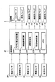
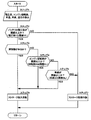
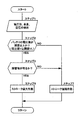
- FIG. 3 It is sectional drawing which shows the whole structure of the compressor by this Embodiment. It is a pneumatic circuit diagram showing an air suspension mechanism using a compressor. It is a block diagram which shows the electrical structure of a vehicle-mounted compression apparatus. It is a flowchart which shows the control processing which the control apparatus in FIG. 3 performs. It is a flowchart which shows the control processing by a 1st modification. It is a flowchart which shows the control processing by the 2nd modification. It is a flowchart which shows the control processing by a 3rd modification.
- the compressor 1 includes a linear motor 2, a compression unit 9 having a cylinder 10 and a piston 11, and an air dryer 17.
- the air dryer 17 side (left side in FIG. 1) of the compressor 1 is defined as one end side
- the linear motor 2 side (right side in FIG. 1) of the compressor 1 is defined as the other end side.
- the linear motor 2 is located on the other end side of the compressor 1 and is provided as a drive source for the compressor 1.
- the linear motor 2 includes a motor case 3 and a linear base 4 that constitute an outer shell of the linear motor 2, an armature 5, a mover 6, a spring 7, and the like.
- the linear motor 2 is connected to a control device 27 described later. That is, in the linear motor 2, the control device 27 controls the current flowing in the coil 5 ⁇ / b> B of the armature 5, thereby causing the mover 6 to reciprocate in the axial direction and cause the piston 11 to generate a reciprocating driving force.
- the motor case 3 is formed as a hollow container made of a metal material such as an aluminum material, for example, and has a bottomed cylindrical shape with one end opened and the other end closed. Inside the motor case 3, an armature 5, a mover 6, a spring 7, and the like are accommodated. A linear base 4 is engaged with the opening end side of the motor case 3 so as to close the opening. In other words, the motor case 3 is fixed to the linear base 4 with screws or the like.
- the armature 5 is fixed in the motor case 3 as a stator.
- the armature 5 includes a core 5A formed of, for example, a powder magnetic core, laminated magnetic steel sheets, and magnetic pieces, and a plurality of coils 5B wound in a predetermined direction and housed in the core 5A. ing.
- the mover 6 is located on the inner peripheral side of the armature 5 and extends along the axial direction (left and right directions in FIG. 1) of the motor case 3. That is, the mover 6 is disposed in the motor case 3 along the central axis of the linear motor 2.
- the mover 6 includes a yoke 6A formed in a flat plate shape using a magnetic material, and a plurality of permanent magnets 6B arranged in a flat plate shape on the front and back surfaces of the yoke 6A.
- the movable element 6 reciprocates in the motor case 3 when a current is applied to the coil 5B of the armature 5.
- mover 6 reciprocates the below-mentioned piston 11 connected to the one end side.
- mover 6 is variably adjusted by control of the control apparatus 27 mentioned later.
- the amount of stroke of the mover 6 can be adjusted by changing the value of the current flowing through the coil 5B of the armature 5, for example, without changing the top dead center of the mover 6 or by adjusting the bottom dead center. This can be done by adjusting the top dead center and the bottom dead center.
- the top dead center of the mover 6 is a position where the mover 6 is moved to the most end side
- the bottom dead center is a position where the mover 6 is moved to the most other end side.
- the spring 7 is located on the other side of the linear motor 2 and is provided in the motor case 3. One end of the spring 7 is fixed to one end of the armature 5 using a connector 7A, and the other end of the spring 7 is attached to the other end of the mover 6 so as to be movable in the axial direction using a connector 7B. It has been.
- the spring 7 is formed by a compression coil spring, for example, and is attached so as to urge the mover 6 toward the other end side of the compressor 1. In this case, the spring 7 expands and contracts in the axial direction as the mover 6 reciprocates.
- the suction port 8 is located at the other end of the linear motor 2 and is provided at the bottom of the motor case 3. This suction port 8 sucks air into the motor case 3 from the outside during the suction stroke of the compressor 1.
- the suction port 8 is connected to a suction conduit 25 described later.
- the compression unit 9 is provided between the linear motor 2 and the air dryer 17.
- the compression unit 9 includes a cylinder 10, a piston 11, an intake valve 12, a valve plate 13, a cylinder head 14, and a discharge valve 16. This compression part 9 drives the piston 11 by the reciprocating motion of the mover 6 of the linear motor 2 to compress the outside air and generate compressed air (working gas).
- the cylinder 10 has one end side closed by a valve plate 13 and the other end side fixed to the linear base 4.
- the cylinder 10 is formed in a cylindrical shape using, for example, an aluminum material, and a piston 11 is accommodated therein so as to be capable of reciprocating (slidable).
- the inside of the cylinder 10 is defined by a non-compression chamber 10A communicating with the inside of the motor case 3 by the piston 11 and a compression chamber 10B on the cylinder head 14 side.
- the piston 11 is inserted in the cylinder 10 so as to be able to reciprocate.
- the piston 11 defines a non-compression chamber 10A and a compression chamber 10B in the cylinder 10.
- the piston 11 is connected to one end side of the mover 6 of the linear motor 2 via a piston pin 11A and a coupling tool 11B.
- the piston 11 is provided along the axial direction of the linear motor 2 (motor case 3).
- the piston 11 is disposed on the axis of the moving direction of the mover 6 of the linear motor 2.
- the piston 11 reciprocates in the cylinder 10 in conjunction with the reciprocation of the mover 6.
- the mover 6 is controlled so that the stroke amount is variably controlled by a control device 27 described later.
- the piston 11 is variably adjusted in the stroke amount in the cylinder 10. That is, when the stroke amount of the mover 6 operates to the maximum, the compressed air supplied from the compression chamber 10B to the air suspension 21 via the air dryer 17 described later increases. Therefore, since the extension operation of the air suspension 21 is performed quickly, the raising operation of the vehicle height can be performed quickly.
- the piston 11 is provided with a communication hole 11C that allows the non-compression chamber 10A and the compression chamber 10B to communicate with each other, and an intake valve 12 is screwed or caulked into the communication hole 11C.
- the intake valve 12 opens the communication hole 11C in the suction stroke of the compressor 1 to connect the non-compression chamber 10A and the compression chamber 10B, and closes the communication hole 11C in the compression stroke to compress the non-compression chamber 10A.
- the chamber 10B is shut off.
- the valve plate 13 and the cylinder head 14 are attached to one end side of the cylinder 10 so as to close one end side of the cylinder 10.
- This cylinder head 14 closes the other end side opening of the air dryer 17 by engaging with the other end side of the air dryer 17 as a discharge portion for discharging compressed air.
- a plurality of fixtures 15 are provided between the cylinder head 14 and the linear base 4 for sandwiching and fixing the cylinder 10 between the cylinder head 14 and the linear base 4.
- the discharge valve 16 is provided between the valve plate 13 and the cylinder head 14 and constitutes a reed valve that is attached to and detached from the valve plate 13.
- the discharge valve 16 is made of a thin circular plate having elasticity (spring property), and is sandwiched between the valve plate 13 and the cylinder head 14.
- the discharge valve 16 is seated on the valve plate 13 in the suction stroke of the compressor 1 to shut off the compression chamber 10B and the air dryer 17, and is separated from the valve plate 13 in the compression stroke to be in the compression chamber 10B and the air dryer 17. To communicate.
- the air dryer 17 is located on one end side of the compressor 1 and is provided on the opposite side of the linear motor 2 with the compression unit 9 interposed therebetween.
- the air dryers 17 are arranged in series so that the axial direction thereof is along the axial direction of the piston 11. That is, the axis of the air dryer 17 and the axis of the piston 11 extend substantially in a straight line.
- the air dryer 17 is disposed on the axis of the moving direction of the mover 6 and the piston 11 of the linear motor 2.
- the air dryer 17 includes a housing 17A, filters 17B1 and 17B2, a desiccant 17C, a spring 17D, and an exhaust pipe 17E.
- the air dryer 17 supplies compressed air (dry air) in a dry state when supplying compressed air from the compressor 1 to each air suspension 21 described later.
- the housing 17A is formed as a hollow container made of a resin material such as resin, and has a bottomed cylindrical shape with one end closed and the other open. The other end of the housing 17A is engaged with the cylinder head 14, thereby closing the open end of the housing 17A.
- the housing 17A is defined by filters 17B1 and 17B2, and the filters 17B1 and 17B2 are filled with a desiccant 17C. The filters 17B1 and 17B2 prevent part of the desiccant 17C from flowing out.
- a spring 17D is provided between the filter 17B2 and the cylinder head 14 to urge the filter 17B2 toward one end of the compressor 1 at all times.
- the housing 17A may be formed of a metal material such as an aluminum material.
- the exhaust pipe 17E passes through the filters 17B1 and 17B2 between the filters 17B1 and 17B2, and is provided so that one end side and the other end side of the air dryer 17 communicate with each other.
- One end side of the exhaust pipe 17E communicates with the exhaust port 19 through an exhaust valve 20 described later, and the other end side of the exhaust pipe 17E communicates with a space between the filter 17B2 and the cylinder head 14.
- the exhaust pipe 17E circulates compressed air (non-dried compressed air in which moisture is not adsorbed by the desiccant 17C) toward the exhaust port 19 in the direction of exhausting it to the outside atmosphere.
- the supply / discharge port 18 is located on one end side of the air dryer 17 and is provided on one circumferential side of the bottom of the housing 17A.
- the supply / discharge port 18 is connected to a supply / exhaust conduit 22 described later, and supplies compressed air compressed in the compression chamber 10 ⁇ / b> B toward the air suspension 21 while being dried by the air dryer 17.
- the exhausted dry compressed air is discharged into the housing 17A of the air dryer 17.
- the exhaust port 19 is located on one end side of the air dryer 17 and is provided on the other side in the circumferential direction of the bottom portion of the housing 17A.
- the exhaust port 19 is connected to an exhaust pipe 26 described later, and exhausts compressed air from the exhaust pipe 17E toward the outside.
- an exhaust valve 20 is provided between the exhaust port 19 and the exhaust pipe 17E.
- the exhaust valve 20 is a valve that communicates and blocks the exhaust port 19 connected to the exhaust pipe line 26 from the atmosphere (outside air).
- the exhaust valve 20 is configured by an ON / OFF type (open / close type) electromagnetic valve, and is connected to a control device 27 described later. That is, the exhaust valve 20 is opened by the control device 27 so that the exhaust port 19 is opened to allow the compressed air to be discharged from the exhaust pipe 17E, and the exhaust port 19 is closed and the compressed air from the exhaust pipe 17E is closed. It is selectively switched to the closed position (b) where the discharge is cut off.
- the exhaust valve 20 is normally closed to block the exhaust pipe 17E from the exhaust port 19. When the exhaust valve 20 is opened, the exhaust pipe 17E is communicated with the exhaust port 19, and the compressed air in the exhaust pipe 17E is discharged (released) into the atmosphere through the exhaust port 19 and the exhaust pipe line 26.
- the air suspension 21 functions as an air spring between the vehicle axle side and the vehicle body side (none shown) so as to correspond to the front, rear, left, and right wheels (none shown) of the vehicle, respectively. There are four in between.
- the air suspension 21 may be provided only on the front wheel side or only on the rear wheel side of the vehicle.
- the air suspension 21 constitutes the pressure device of the present invention, and is supplied with the working fluid (compressed air) compressed in the compression chamber 10 ⁇ / b> B of the compressor 1.
- each air suspension 21 expands or contracts upward or downward according to the supply / discharge amount (compressed air amount) at this time, and adjusts the vehicle height. Is supported so as to be movable upward and downward.
- These air suspensions 21 are connected to the compressor 1 via supply / exhaust pipelines 22 and branch pipelines 23.
- One end side of the supply / exhaust pipe line 22 located on the upstream side thereof is connected to the supply / exhaust port 18 of the compressor 1, and the other end side located on the downstream side thereof is connected to each branch pipe line 23.
- the supply / exhaust conduit 22 and the branch conduits 23 supply / discharge compressed air to / from the air suspensions 21.
- the supply / exhaust valve 24 is located between each air suspension 21 and the compressor 1 and is provided in the middle of each branch pipe 23.
- the air supply / exhaust valve 24 is configured by an ON / OFF type electromagnetic valve in substantially the same manner as the exhaust valve 20 and is connected to a control device 27 described later. That is, the air supply / exhaust valve 24 is controlled by the control device 27 to open each branch line 23 and open / close the branch line 23 with the open position (c) allowing the compressed air to be supplied to and discharged from each air suspension 21. It is selectively switched to a closed position (d) where the supply and discharge of compressed air to each air suspension 21 is shut off.
- the suction pipe 25 is connected to the suction port 8 of the compressor 1.
- the suction pipe 25 is always in communication with the atmosphere, and allows the air sucked from the intake filter 25A to flow into the compressor 1.
- the exhaust pipe line 26 is connected to the exhaust port 19 of the compressor 1.
- This exhaust pipe 26 is always in communication with the atmosphere, and when the exhaust valve 20 is opened, it communicates with the exhaust pipe 17E through the exhaust port 19, and the compressed air in the exhaust pipe 17E is discharged (released) into the atmosphere. To do.
- the control device 27 is mounted on the vehicle and controls the driving of the linear motor 2 according to the state (driving state) of the vehicle.
- the control device 27 constitutes the on-vehicle compression device of the present invention together with the compressor 1.
- a voltage sensor 28 serving as a battery voltage detecting unit for detecting a battery voltage of a battery (not shown) mounted on the vehicle, and a rotational speed for detecting the rotational speed of an engine (not shown).
- a sensor 29, a speed sensor 30 for detecting the traveling speed of the vehicle, a vehicle height sensor 31 for detecting the height dimension (vehicle height) of the vehicle, and a pressure sensor 32 for detecting air pressure acting on the air suspension 21 are connected. .
- the rotational speed sensor 29 constitutes a rotational speed detection section of the present invention
- the speed sensor 30 constitutes a speed detection section of the present invention
- the pressure sensor 32 is provided in the air suspension 21, for example, the vehicle height sensor 31 is provided in the vehicle body, and these sensors 31 and 32 constitute the obstacle detection unit of the present invention.
- the linear motor 2 of the compressor 1 (the coil 5B of the armature 5), the exhaust valve 20 of the compressor 1, and the supply / exhaust valve 24 provided in each branch line 23 are connected to the output side of the control device 27.
- the control device 27 detects each air suspension 21 when, for example, it is determined that the vehicle height adjustment is necessary according to the vehicle state (driving state) and when the vehicle height adjustment switch (not shown) is operated by the driver.
- the linear motor 2, the exhaust valve 20, and each supply / exhaust valve 24 are controlled in order to expand or contract the above and below.
- the control device 27 includes a battery voltage determination unit 27A, a rotation speed determination unit 27B, a speed determination unit 27C, an obstacle determination unit 27D, and a memory 27E.
- the battery voltage determination unit 27A determines, based on the detection signal output from the voltage sensor 28, whether or not the battery voltage value V is equal to or greater than a voltage threshold value VL (predetermined voltage value VL) stored in the memory 27E. It is.
- the voltage threshold value VL can be set to be equal to or higher than the voltage value necessary for maximizing the stroke amount of the mover 6.
- the case where the battery voltage is lower than the voltage threshold VL may be due to deterioration over time, or in the case of an electric vehicle, the amount of charge may be reduced due to traveling of the vehicle, and the amount of battery charge may be reduced.
- the rotational speed determination unit 27B determines whether or not the engine rotational speed N is equal to or greater than the rotational speed threshold value NL (predetermined rotational speed NL) stored in the memory 27E.
- the rotation speed threshold NL can be set by, for example, an experimental value based on the noise performance of the engine, the noise performance of the vehicle, or the like.
- the speed determination unit 27C determines whether or not the vehicle speed S is equal to or higher than a speed threshold SL (predetermined speed SL) stored in the memory 27E in advance based on the detection signal output from the speed sensor 30.
- a speed threshold SL is set, for example, by an experimental value based on noise performance corresponding to the traveling speed of the vehicle (contact noise between the road surface and the tire when the vehicle travels, wind noise, etc., hereinafter referred to as road noise). Can do. That is, the road noise usually increases as the traveling speed of the vehicle increases. Therefore, the speed determination unit 27C determines by replacing the road noise with the traveling speed of the vehicle.
- the obstacle determination unit 27D determines whether there is an obstacle in the upper or lower direction of the vehicle based on the detection signals output from the vehicle height sensor 31 and the pressure sensor 32. In this case, the obstacle determination unit 27D observes temporal changes between the detection value of the vehicle height sensor 31 and the detection value of the pressure sensor 32 to determine whether there is an obstacle in the upward or downward direction of the vehicle. Deciding.
- the obstacle determination unit 27D for example, when the detection value of the pressure sensor 32 is greatly reduced while the detection value of the vehicle height sensor 31 is fixed to a constant value for a predetermined time. It can be determined that there is an obstacle (in contact) below the vehicle. Further, the obstacle determination unit 27D, for example, when the detection value of the pressure sensor 32 is greatly increased even though the detection value of the vehicle height sensor 31 is fixed to a constant value for a predetermined time. It can be determined that there is an obstacle above (in contact with).
- the memory 27E is composed of, for example, a flash memory, ROM, RAM, EEPROM, or the like.
- the processing program for determining whether or not there is an obstacle in the upward or downward direction of the vehicle in addition to the processing program for determining whether or not there is an obstacle in the upward or downward direction of the vehicle, the processing program for executing the processing flow shown in FIG.
- a processing program for determining whether the stroke of the movable element 6 is to be maximally operated or shortened is stored.
- the memory 27E stores various predetermined values (voltage threshold value VL, rotation speed threshold value NL, speed threshold value SL) used in the processing program.
- the state of the vehicle that is, the battery voltage value V, the engine speed N, the vehicle speed S, and the presence or absence of an obstacle (vehicle height, air pressure) are stored (saved) in the memory 27E so as to be sequentially updated.
- the on-vehicle compression device has the above-described configuration, and the operation thereof will be described next.
- the permanent magnet 6 ⁇ / b> B of the mover 6 receives thrust in the axial direction, and moves the entire mover 6 toward one end side of the compressor 1.
- the mover 6 moves toward the other end of the compressor 1 by the urging force of the spring 7 by reversing the direction of the current.
- the thrust of the reciprocating motion of the mover 6 is transmitted to the piston 11 via the connector 11B.
- the piston 11 reciprocates in the cylinder 10 and alternately repeats a suction stroke in which the piston 11 moves away from the cylinder head 14 and a compression stroke in which the piston 11 approaches the cylinder head 14.
- the pressure in the compression chamber 10B increases, and when the pressure in the compression chamber 10B becomes higher than the valve opening pressure of the discharge valve 16, the discharge valve 16 opens.
- the compressed air in the compression chamber 10 ⁇ / b> B flows into the air dryer 17.
- the air dryer 17 adsorbs and removes moisture by bringing the compressed air into contact with the desiccant 17 ⁇ / b> C, and supplies the dried compressed air toward the air suspension 21 through the supply / discharge port 18.
- the air supply / exhaust valve 24 is switched from the closed position (d) to the open position (c).
- the compressed air is supplied to each air suspension 21 via the supply / discharge line 22 and the branch line 23.
- the air supply / exhaust valve 24 is switched to the closed position (d) to close the branch pipe 23.
- the air supply / exhaust valve 24 is switched to the open position (c) and the exhaust valve 20 is switched from the closed position (b) to the open position (a).
- the compressed air in each air suspension 21 is led out into the compressor 1 through the branch line 23 and the supply / discharge line 22.
- the compressed air that has flowed into the compressor 1 through the supply / discharge port 18 flows back in the air dryer 17 to take away moisture adsorbed by the desiccant 17C, and regenerates the desiccant 17C.
- the compressed air is discharged (released) to the outside through the exhaust pipe 17E, the exhaust valve 20, the exhaust port 19, and the exhaust pipe 26.
- the compressed air is discharged from each air suspension 21, and each air suspension 21 shifts to a contracted state, whereby the vehicle height can be lowered.
- the linear motor 2 is used for the compressor 1.
- the compressor 1 can be operated even when the supply battery voltage is low. Further, by shortening the stroke of the mover 6, the compressor 1 can be operated with low vibration and low noise.
- control processing shown in FIG. 4 is performed until the vehicle height adjustment is completed after the vehicle control device determines that the vehicle height adjustment is necessary or after the vehicle height adjustment switch is turned on by the driver. It is repeatedly executed every predetermined period.
- the control device 27 When the processing operation of FIG. 4 is started, the control device 27 outputs the voltage value V of the battery output from the voltage sensor 28 in step 1, the engine speed N output from the speed sensor 29, and the speed sensor 30.
- the detected vehicle speed S, the vehicle height output from the vehicle height sensor 31, and the air pressure acting on the air suspension 21 output from the pressure sensor 32 are detected. These detection values are stored in the memory 27E of the control device 27 in an updatable manner.
- step 2 it is determined whether or not the battery voltage value V is equal to or higher than the voltage threshold VL (voltage value V ⁇ threshold VL). That is, the battery voltage determination unit 27A of the control device 27 determines whether or not the battery has a voltage value sufficient to operate the movable element 6 with the maximum stroke. If “YES” in step 2, that is, if it is determined that the voltage value V is greater than or equal to the threshold value VL, the process proceeds to step 3. On the other hand, if “NO” in step 2, that is, if it is determined that the voltage value V is less than the threshold value VL, the process proceeds to step 7.
- step 3 it is determined whether there is an obstacle. That is, the obstacle determination unit 27D of the control device 27 determines whether there is an obstacle above or below the vehicle. Specifically, the obstacle determination unit 27D, for example, when the detection value of the pressure sensor 32 is greatly reduced while the detection value of the vehicle height sensor 31 is fixed to a constant value for a predetermined time. It can be determined that there is an obstacle (in contact) below the vehicle. Further, the obstacle determination unit 27D, for example, when the detection value of the pressure sensor 32 is greatly increased even though the detection value of the vehicle height sensor 31 is fixed to a constant value for a predetermined time. It can be determined that there is an obstacle above (in contact with).
- the process proceeds to another control process (not shown). Specifically, the control device 27 stops the expansion operation of the air suspension 21 (stops the operation of the compressor 1), switches the supply / exhaust valve 24 to the open position (c), and closes the exhaust valve 20 to the closed position. Switching from (b) to the open position (a). Accordingly, the compressed air is discharged from the air suspension 21 and each air suspension 21 shifts to a contracted state, whereby the vehicle height can be lowered.
- step 3 If “YES” in step 3, that is, if it is determined that there is an obstacle below the vehicle, the process proceeds to step 6. On the other hand, if “NO” in step 3, that is, if it is determined that there is no obstacle (no obstacle is detected), the process proceeds to step 4.
- step 4 it is determined whether or not the engine speed N is equal to or higher than the speed threshold NL (speed N ⁇ threshold NL). That is, the rotational speed determination unit 27B of the control device 27 compares the engine driving sound based on the engine rotational speed N with the driving sound of the compressor 1 when the movable element 6 of the compressor 1 is operated with the maximum stroke. Judge whether it is large or not. If “YES” in step 4, that is, if it is determined that the engine speed N is greater than or equal to the threshold NL, the process proceeds to step 6. On the other hand, if “NO” in the step 4, that is, if it is determined that the engine speed N is lower than the threshold value NL, the process proceeds to a step 5.
- Step 5 determines whether or not the vehicle speed S is equal to or higher than the speed threshold SL (vehicle speed S ⁇ threshold SL). That is, the speed determination unit 27C of the control device 27 determines whether or not the road noise based on the vehicle speed S is larger than the driving sound of the compressor 1 when the movable element 6 of the compressor 1 is operated with the maximum stroke. Replace with the vehicle speed. If “YES” in step 5, that is, if it is determined that the vehicle speed S is equal to or higher than the threshold SL, the process proceeds to step 6. On the other hand, if “NO” in the step 5, that is, if it is determined that the vehicle speed S is slower than the threshold SL, the process proceeds to a step 7.
- Step 6 sets the stroke of the mover 6 to maximum operation. That is, the control device 27 supplies a current to the coil 5B of the armature 5 so that the stroke of the mover 6 is maximized. As a result, compressed air can be quickly supplied from the compressor 1 to the air suspension 21, and as a result, the vehicle height can be quickly raised.
- the collision with the obstacle can be quickly avoided.
- the engine speed N is equal to or higher than the threshold NL (“YES” in step 4) and / or when the vehicle speed S is equal to or higher than the threshold SL (“YES” in step 5)
- the vehicle interior noise engine drive sound, Road noise, etc.
- the stroke of the mover 6 of the compressor 1 is operated to the maximum, the driving sound of the compressor 1 is not noticeable, and the responsiveness of the air suspension 21 can be increased and the vehicle height can be raised quickly.
- Step 7 is to shorten the stroke of the mover 6. That is, the control device 27 supplies a current to the coil 5B of the armature 5 so that the stroke of the mover 6 becomes small.
- the bottom dead center is adjusted without changing the top dead center of the mover 6, for example, by changing the current value flowing through the coil 5 ⁇ / b> B of the armature 5. Or by adjusting the top dead center and the bottom dead center of the mover 6.
- the compressor 1 can be driven with low current, low vibration, and low noise (low noise). Accordingly, even when the supply voltage of the battery is low (“NO” in step 2), the compressor 1 can be driven with a low current by shortening the stroke of the mover 6 and thus raising the vehicle height. be able to.
- the engine speed N is less than the threshold value NL (“NO” in step 4) and the vehicle speed S is less than the threshold value SL (“NO” in step 5), the surroundings of the vehicle (inside the vehicle) is kept quiet. Therefore, even if the battery has a voltage value V sufficient to operate the stroke of the mover 6 at the maximum, the stroke of the mover 6 is shortened. As a result, the vibration of the mover 6 is reduced, and consequently the driving sound (noise) of the compressor 1 can be reduced, so that the vehicle height can be adjusted while maintaining the quietness in the vehicle.
- Step 3 to Step 5 are in no particular order.
- whether or not the stroke of the mover 6 is shortened by determining whether there is an obstacle in step 3, determining the engine speed N in step 4, and determining the vehicle speed S in step 5.
- the case where it was determined was described as an example.
- the present invention is not limited to this.
- the stroke amount of the mover 6 may be determined.
- the stroke amount of the mover 6 is determined only by determining the engine speed N without determining whether there is an obstacle and determining the vehicle speed S. May be. Further, as in the third modification shown in FIG. 7, the stroke amount of the mover 6 is determined only by the determination of the vehicle speed S without determining whether there is an obstacle and determining the engine speed N. May be.
- the compressor 1 is configured to be used in an open type air suspension mechanism that sucks and exhausts outside air that does not use a compressed air storage tank.
- the present invention is not limited to this.
- the compressor 1 may be used in a closed type air suspension mechanism using a compressed air storage tank. It can be applied to an open type tank.
- step 6 the stroke amount of the mover 6 can be determined as the maximum operation. That is, when it is determined that there is an obstacle above the vehicle, the air suspension can be quickly reduced by maximizing the stroke amount of the mover 6. The same applies to the first modification.
- the vehicle body includes an obstacle detection device (obstacle detection unit) including a plurality of clearance sonars, millimeter wave radars, etc., and these obstacle detection devices detect obstacles. May be.
- obstacle detection device obstacle detection unit
- the stroke amount of the mover 6 is selected as the two-step selection control of the maximum operation or the shortening operation has been described as an example.
- the present invention is not limited to this.
- the stroke amount of the movable element 6 may be switched in multiple steps or continuously according to the state of the vehicle.
- the battery state is the battery voltage value V, the engine speed N, and the vehicle speed S has been described as an example.
- the present invention is not limited to this.
- a gear position and / or a brake switch ON or OFF may be used as the vehicle state.
- the gear position is parked or neutral, it is considered that the vehicle is stopped, and the stroke amount of the mover 6 can be shortened.
- the brake switch is turned on, that is, when the apply operation is performed, it is considered that the vehicle is stopped, and the stroke amount of the mover 6 can be shortened.
- a compressor having a cylinder and a piston that is slidably provided in the cylinder and forms a compression chamber, and a movable that is reciprocally connected to the piston.
- a linear motor having a child, and a control device that controls driving of the linear motor.
- the on-vehicle compression device supplies the working fluid compressed in the compression chamber to a pressure device provided in the vehicle, and the control device variably adjusts the stroke of the piston according to the state of the vehicle.
- control device adjusts the bottom dead center without changing the top dead center of the mover.
- control device adjusts a top dead center and a bottom dead center of the movable element.
- the state of the vehicle includes the rotational speed of the engine of the vehicle.
- the on-vehicle compression device further includes a rotational speed detection unit that detects the rotational speed of the engine of the vehicle.
- the controller adjusts the piston stroke to be small when the engine speed detected by the engine speed detector is lower than a predetermined engine speed.
- the in-vehicle compression device further includes a speed detection unit that detects the speed of the vehicle.
- the control device adjusts the stroke of the piston to be small when the speed of the vehicle detected by the speed detector is slower than a predetermined speed.
- the in-vehicle compression device includes an obstacle detection unit that detects the presence or absence of an obstacle located above or below the vehicle.
- the control device adjusts the piston stroke to be small when the obstacle detection unit does not detect the obstacle.
- the state of the vehicle includes a battery voltage of the vehicle.
- the on-vehicle compression device further includes a battery voltage detection unit that detects a battery voltage of the vehicle.
- the control device adjusts the stroke of the piston to be small when the battery voltage detected by the battery voltage detector is lower than a predetermined voltage value.
- the state of the vehicle includes a battery voltage of the vehicle.
- the on-vehicle compression device further includes a battery voltage detection unit that detects a battery voltage of the vehicle.
- the controller adjusts the stroke of the piston to be small when the amount of charge of the battery voltage detected by the battery voltage detector is small.
Landscapes
- Engineering & Computer Science (AREA)
- Mechanical Engineering (AREA)
- General Engineering & Computer Science (AREA)
- Vehicle Body Suspensions (AREA)
- Control Of Positive-Displacement Pumps (AREA)
- Compressors, Vaccum Pumps And Other Relevant Systems (AREA)
Abstract
Description
Claims (8)
- 車載圧縮装置であって、
シリンダと、該シリンダ内に摺動可能に設けられ、圧縮室を形成するピストンと、を有する圧縮機と、
該ピストンに往復動可能に接続される可動子を有するリニアモータと、
該リニアモータの駆動を制御する制御装置と、
を備え、
前記車載圧縮装置は、前記圧縮室で圧縮した作動流体を車両に設けられた圧力装置に供給し、
前記制御装置は、前記車両の状態に応じて前記ピストンのストロークを可変に調整する
車載圧縮装置。 - 請求項1に記載の車載圧縮装置であって、
前記制御装置は、前記可動子の上死点を変更することなく、下死点を調整する
車載圧縮装置。 - 請求項1に記載の車載圧縮装置であって、
前記制御装置は、前記可動子の上死点と下死点とを調整する
車載圧縮装置。 - 請求項1乃至3の何れかに記載の車載圧縮装置であって、
前記車両の状態は、前記車両のエンジンの回転数を含み、
前記車載圧縮装置は、さらに、前記車両のエンジンの回転数を検出する回転数検出部を備え、
前記制御装置は、前記回転数検出部により検出された前記エンジンの回転数が所定の回転数よりも低いとき、前記ピストンのストロークを、小さくするように調整する
車載圧縮装置。 - 請求項1乃至4の何れかに記載の車載圧縮装置であって、
さらに、前記車両の速度を検出する速度検出部を備え、
前記制御装置は、前記速度検出部により検出された前記車両の速度が所定の速度よりも遅いとき、前記ピストンのストロークを、小さくするように調整する
車載圧縮装置。 - 請求項1乃至5の何れかに記載の車載圧縮装置であって、
前記車両の上方または下方に位置する障害物の有無を検出する障害物検出部を備え、
前記制御装置は、前記障害物検出部により前記障害物が検出されないとき、前記ピストンのストロークを、小さくするように調整する
車載圧縮装置。 - 請求項1乃至6の何れかに記載の車載圧縮装置であって、
前記車両の状態は、前記車両のバッテリ電圧を含み、
前記車載圧縮装置は、さらに、前記車両のバッテリ電圧を検出するバッテリ電圧検出部を備え、
前記制御装置は、前記バッテリ電圧検出部により検出された前記バッテリ電圧が所定の電圧値よりも低い時、前記ピストンのストロークを、小さくするように調整する
車載圧縮装置。 - 請求項1乃至6の何れかに記載の車載圧縮装置であって、
前記車両の状態は、前記車両のバッテリ電圧を含み、
前記車載圧縮装置は、さらに、前記車両のバッテリ電圧を検出するバッテリ電圧検出部を備え、
前記制御装置は、前記バッテリ電圧検出部により検出された前記バッテリの充電量が少ない時、前記ピストンのストロークを、小さくするように調整する
車載圧縮装置。
Priority Applications (5)
| Application Number | Priority Date | Filing Date | Title |
|---|---|---|---|
| KR1020187033996A KR102194660B1 (ko) | 2016-05-26 | 2017-05-16 | 차재 압축 장치 |
| CN201780032443.0A CN109312734B (zh) | 2016-05-26 | 2017-05-16 | 车载压缩装置 |
| US16/303,760 US11015593B2 (en) | 2016-05-26 | 2017-05-16 | In-vehicle compression device |
| DE112017002632.6T DE112017002632B4 (de) | 2016-05-26 | 2017-05-16 | Fahrzeuginterne Kompressionsvorrichtung |
| JP2018519206A JP6782771B2 (ja) | 2016-05-26 | 2017-05-16 | 車載圧縮装置 |
Applications Claiming Priority (2)
| Application Number | Priority Date | Filing Date | Title |
|---|---|---|---|
| JP2016105122 | 2016-05-26 | ||
| JP2016-105122 | 2016-05-26 |
Publications (1)
| Publication Number | Publication Date |
|---|---|
| WO2017204037A1 true WO2017204037A1 (ja) | 2017-11-30 |
Family
ID=60412812
Family Applications (1)
| Application Number | Title | Priority Date | Filing Date |
|---|---|---|---|
| PCT/JP2017/018360 Ceased WO2017204037A1 (ja) | 2016-05-26 | 2017-05-16 | 車載圧縮装置 |
Country Status (6)
| Country | Link |
|---|---|
| US (1) | US11015593B2 (ja) |
| JP (1) | JP6782771B2 (ja) |
| KR (1) | KR102194660B1 (ja) |
| CN (1) | CN109312734B (ja) |
| DE (1) | DE112017002632B4 (ja) |
| WO (1) | WO2017204037A1 (ja) |
Cited By (1)
| Publication number | Priority date | Publication date | Assignee | Title |
|---|---|---|---|---|
| CN109795278A (zh) * | 2019-03-28 | 2019-05-24 | 西安科技大学 | 一种车辆混合悬架作动器及其多模式协调切换控制方法 |
Families Citing this family (6)
| Publication number | Priority date | Publication date | Assignee | Title |
|---|---|---|---|---|
| EP3260338A1 (de) * | 2016-06-23 | 2017-12-27 | Adolf Kochsiek | Pneumatisches system für kraftfahrzeuge |
| JP7077097B2 (ja) * | 2018-03-28 | 2022-05-30 | 日立Astemo株式会社 | エアサスペンションシステム、および、カメラ洗浄システム |
| KR102729868B1 (ko) * | 2019-11-12 | 2024-11-12 | 현대자동차주식회사 | 차량의 에어 서스펜션 제어 장치 및 방법 |
| CN110861462B (zh) * | 2019-12-02 | 2022-10-04 | 西安科技大学 | 一种基于图像识别的整车智能混合悬架协调控制系统 |
| DE102025100768A1 (de) | 2025-01-10 | 2026-07-16 | Dr. Ing. H.C. F. Porsche Aktiengesellschaft | Verfahren zur Steuerung einer Luftfederung sowie Kraftfahrzeug mit einer Luftfederung |
| US12552218B1 (en) * | 2025-04-10 | 2026-02-17 | GM Global Technology Operations LLC | Air spring suspension system with variable flow valves |
Citations (3)
| Publication number | Priority date | Publication date | Assignee | Title |
|---|---|---|---|---|
| JPH10119530A (ja) * | 1996-10-23 | 1998-05-12 | Isuzu Motors Ltd | 油圧式懸架機構の油圧供給装置 |
| JP2003254251A (ja) * | 2002-02-28 | 2003-09-10 | Samsung Electronics Co Ltd | リニア圧縮機の制御装置及び制御方法 |
| JP2010159648A (ja) * | 2009-01-06 | 2010-07-22 | Kobelco Contstruction Machinery Ltd | ハイブリッド作業機械の動力源装置 |
Family Cites Families (11)
| Publication number | Priority date | Publication date | Assignee | Title |
|---|---|---|---|---|
| US4343275A (en) * | 1974-03-22 | 1982-08-10 | Holec, N.V. | Electromagnetically actuated pumps |
| DE19918930B4 (de) | 1999-04-26 | 2006-04-27 | Lg Electronics Inc. | Leistungssteuervorrichtung für einen Linearkompressor und ebensolches Verfahren |
| KR100408068B1 (ko) | 2001-07-31 | 2003-12-03 | 엘지전자 주식회사 | 왕복동식 압축기의 스트로크 제어장치 및 방법 |
| JP2003339188A (ja) * | 2002-05-21 | 2003-11-28 | Matsushita Electric Ind Co Ltd | リニアモータの駆動装置 |
| KR100806099B1 (ko) | 2006-04-14 | 2008-02-21 | 엘지전자 주식회사 | 리니어 압축기의 운전제어장치 및 방법 |
| JP2008184131A (ja) * | 2007-01-31 | 2008-08-14 | Hitachi Ltd | 車載圧縮装置及びその制御方法 |
| CN101776067B (zh) * | 2009-01-14 | 2012-11-21 | 中国科学院理化技术研究所 | 线性压缩机变容量调节的定余隙装置 |
| US9441625B2 (en) * | 2013-01-11 | 2016-09-13 | Mary Ann Schoendorff | System and method for pump component controlling and testing |
| DE102013003513A1 (de) * | 2013-03-04 | 2014-09-04 | Wabco Gmbh | Verdichteranordnung zum Betreiben einer Druckluftversorgungsanlage, Druckluftversorgungsanlage und Druckluftversorgungssystem sowie Fahrzeug mit einer solchen Druckluftversorgungsanlage |
| JP2016105122A (ja) | 2014-12-01 | 2016-06-09 | パナソニックIpマネジメント株式会社 | 照明装置および映像表示装置 |
| JP6466300B2 (ja) | 2015-09-25 | 2019-02-06 | 日立オートモティブシステムズ株式会社 | エアサスペンションシステム |
-
2017
- 2017-05-16 KR KR1020187033996A patent/KR102194660B1/ko not_active Expired - Fee Related
- 2017-05-16 WO PCT/JP2017/018360 patent/WO2017204037A1/ja not_active Ceased
- 2017-05-16 US US16/303,760 patent/US11015593B2/en active Active
- 2017-05-16 JP JP2018519206A patent/JP6782771B2/ja not_active Expired - Fee Related
- 2017-05-16 CN CN201780032443.0A patent/CN109312734B/zh not_active Expired - Fee Related
- 2017-05-16 DE DE112017002632.6T patent/DE112017002632B4/de not_active Expired - Fee Related
Patent Citations (3)
| Publication number | Priority date | Publication date | Assignee | Title |
|---|---|---|---|---|
| JPH10119530A (ja) * | 1996-10-23 | 1998-05-12 | Isuzu Motors Ltd | 油圧式懸架機構の油圧供給装置 |
| JP2003254251A (ja) * | 2002-02-28 | 2003-09-10 | Samsung Electronics Co Ltd | リニア圧縮機の制御装置及び制御方法 |
| JP2010159648A (ja) * | 2009-01-06 | 2010-07-22 | Kobelco Contstruction Machinery Ltd | ハイブリッド作業機械の動力源装置 |
Cited By (1)
| Publication number | Priority date | Publication date | Assignee | Title |
|---|---|---|---|---|
| CN109795278A (zh) * | 2019-03-28 | 2019-05-24 | 西安科技大学 | 一种车辆混合悬架作动器及其多模式协调切换控制方法 |
Also Published As
| Publication number | Publication date |
|---|---|
| JPWO2017204037A1 (ja) | 2019-03-07 |
| DE112017002632T5 (de) | 2019-04-11 |
| JP6782771B2 (ja) | 2020-11-11 |
| KR102194660B1 (ko) | 2020-12-23 |
| CN109312734B (zh) | 2020-12-25 |
| DE112017002632B4 (de) | 2020-08-06 |
| US11015593B2 (en) | 2021-05-25 |
| US20190085841A1 (en) | 2019-03-21 |
| KR20190002558A (ko) | 2019-01-08 |
| CN109312734A (zh) | 2019-02-05 |
Similar Documents
| Publication | Publication Date | Title |
|---|---|---|
| JP6782771B2 (ja) | 車載圧縮装置 | |
| JP7077097B2 (ja) | エアサスペンションシステム、および、カメラ洗浄システム | |
| JP3963619B2 (ja) | 冷凍サイクルの圧縮容量制御装置 | |
| US11319943B2 (en) | Compressor | |
| CN106232398A (zh) | 集成的空气供给单元 | |
| CN108025613A (zh) | 空气悬架系统 | |
| JP6618542B2 (ja) | 圧縮装置 | |
| JP6740343B2 (ja) | 車載用圧縮機を搭載した車両 | |
| JP2008184131A (ja) | 車載圧縮装置及びその制御方法 | |
| JP6264536B2 (ja) | エアコンプレッサ装置 | |
| KR101575482B1 (ko) | 전동구동장치 통합형 전동식 파워스티어링 시스템 및 그 제어방법 | |
| JP6705731B2 (ja) | コンプレッサおよびエアサスペンションシステム | |
| JP2021050665A (ja) | 圧縮機 | |
| US20210348601A1 (en) | Compressor device | |
| JP2019093871A (ja) | 電気自動車用制動トルク発生装置および電気自動車 | |
| CN102667155A (zh) | 用于车辆的空调压缩机、车辆 | |
| KR101987686B1 (ko) | 공압 조절장치 및 이를 이용한 자동차용 쇽업소버 시스템 | |
| KR101550980B1 (ko) | 전동구동장치 통합형 전동식 파워스티어링 시스템 및 그 제어방법 | |
| KR20160013333A (ko) | 용량 가변형 사판식 압축기 | |
| JP2019095043A (ja) | 電気自動車用制動トルク発生装置および電気自動車 | |
| JP2006348957A (ja) | 冷凍サイクルの圧縮容量制御装置 | |
| KR20170040991A (ko) | 전자기 펌프 | |
| JP2000009041A (ja) | 容量可変圧縮機の容量制御装置 | |
| JP2008032026A (ja) | 冷凍サイクルの圧縮容量制御装置 | |
| JP2006348957A5 (ja) |
Legal Events
| Date | Code | Title | Description |
|---|---|---|---|
| ENP | Entry into the national phase |
Ref document number: 2018519206 Country of ref document: JP Kind code of ref document: A |
|
| ENP | Entry into the national phase |
Ref document number: 20187033996 Country of ref document: KR Kind code of ref document: A |
|
| 121 | Ep: the epo has been informed by wipo that ep was designated in this application |
Ref document number: 17802629 Country of ref document: EP Kind code of ref document: A1 |
|
| 122 | Ep: pct application non-entry in european phase |
Ref document number: 17802629 Country of ref document: EP Kind code of ref document: A1 |