WO2017200274A2 - Curved panel bonding unit and curved panel bonding apparatus comprising same - Google Patents
Curved panel bonding unit and curved panel bonding apparatus comprising same Download PDFInfo
- Publication number
- WO2017200274A2 WO2017200274A2 PCT/KR2017/005075 KR2017005075W WO2017200274A2 WO 2017200274 A2 WO2017200274 A2 WO 2017200274A2 KR 2017005075 W KR2017005075 W KR 2017005075W WO 2017200274 A2 WO2017200274 A2 WO 2017200274A2
- Authority
- WO
- WIPO (PCT)
- Prior art keywords
- panel
- fixing device
- pressing member
- housing
- curved
- Prior art date
Links
Images


Classifications
-
- G—PHYSICS
- G02—OPTICS
- G02F—OPTICAL DEVICES OR ARRANGEMENTS FOR THE CONTROL OF LIGHT BY MODIFICATION OF THE OPTICAL PROPERTIES OF THE MEDIA OF THE ELEMENTS INVOLVED THEREIN; NON-LINEAR OPTICS; FREQUENCY-CHANGING OF LIGHT; OPTICAL LOGIC ELEMENTS; OPTICAL ANALOGUE/DIGITAL CONVERTERS
- G02F1/00—Devices or arrangements for the control of the intensity, colour, phase, polarisation or direction of light arriving from an independent light source, e.g. switching, gating or modulating; Non-linear optics
- G02F1/01—Devices or arrangements for the control of the intensity, colour, phase, polarisation or direction of light arriving from an independent light source, e.g. switching, gating or modulating; Non-linear optics for the control of the intensity, phase, polarisation or colour
- G02F1/13—Devices or arrangements for the control of the intensity, colour, phase, polarisation or direction of light arriving from an independent light source, e.g. switching, gating or modulating; Non-linear optics for the control of the intensity, phase, polarisation or colour based on liquid crystals, e.g. single liquid crystal display cells
- G02F1/1303—Apparatus specially adapted to the manufacture of LCDs
-
- G—PHYSICS
- G02—OPTICS
- G02F—OPTICAL DEVICES OR ARRANGEMENTS FOR THE CONTROL OF LIGHT BY MODIFICATION OF THE OPTICAL PROPERTIES OF THE MEDIA OF THE ELEMENTS INVOLVED THEREIN; NON-LINEAR OPTICS; FREQUENCY-CHANGING OF LIGHT; OPTICAL LOGIC ELEMENTS; OPTICAL ANALOGUE/DIGITAL CONVERTERS
- G02F1/00—Devices or arrangements for the control of the intensity, colour, phase, polarisation or direction of light arriving from an independent light source, e.g. switching, gating or modulating; Non-linear optics
- G02F1/01—Devices or arrangements for the control of the intensity, colour, phase, polarisation or direction of light arriving from an independent light source, e.g. switching, gating or modulating; Non-linear optics for the control of the intensity, phase, polarisation or colour
- G02F1/13—Devices or arrangements for the control of the intensity, colour, phase, polarisation or direction of light arriving from an independent light source, e.g. switching, gating or modulating; Non-linear optics for the control of the intensity, phase, polarisation or colour based on liquid crystals, e.g. single liquid crystal display cells
- G02F1/133—Constructional arrangements; Operation of liquid crystal cells; Circuit arrangements
- G02F1/1333—Constructional arrangements; Manufacturing methods
- G02F1/133305—Flexible substrates, e.g. plastics, organic film
Definitions
- the present invention relates to a curved panel bonding unit and a curved panel bonding apparatus including the same, and more particularly, to a curved panel bonding unit capable of precisely and quickly bonding other panels to the curved panel and a curved panel bonding apparatus including the same It is about.
- the flat panel display includes a liquid crystal display (LCD), a plasma display device (PDP), an organic light emitting diode (OLED), and the like.
- the liquid crystal display is widely used as a display device of various digital devices due to features such as light weight, thinness, low power driving, full color, and high resolution.
- the liquid crystal display device is manufactured by bonding a polarizing plate and a backlight unit to a liquid crystal display panel that controls light transmittance.
- the plasma display device is manufactured by arranging electrodes crossing each other on two panels facing each other.
- Various flat panel display devices including such liquid crystal display devices and plasma display devices are manufactured by bonding a panel having various functions such as a transparent protective plate to a flat panel display panel.
- the touch panel is an input device installed on the display surfaces of various flat panel display devices and used to allow a user to select desired information while viewing the display device.
- the touch panel includes a resistive type, a capacitive type, an electro-magnetic type (EM), a saw type and an infrared type.
- the touch panel is manufactured by bonding a transparent conductive electrode panel to a window panel made of a transparent material.
- An object of the present invention is to provide a curved panel bonding unit and a curved panel bonding apparatus including the same, which can accurately and quickly bond other panels to the curved panel.
- the present invention provides a curved panel bonding unit and a curved panel bonding apparatus including the same
- the curved panel bonding unit comprises: a housing having a vacuum chamber and an entrance opening to the outside; A panel pressing member installed in the vacuum chamber; A first panel fixing device provided with fixing means for fixing the first panel and installed in the vacuum chamber; At least one first support column passing through any one or more of a plurality of through holes provided in the bottom surface of the housing to support the first panel fixing device; At least one second support column passing through any one or more of a plurality of through holes provided in the bottom surface of the housing to support the panel pressing member; An inversion frame disposed in the vacuum chamber than the panel pressurizing member and having a second panel fixing device configured to fix a second panel for attaching to the first panel; An inversion device for inverting an upper and lower surfaces of the inversion frame such that one surface of the second panel fixed to the second panel fixing device faces the first panel; And an elevating device for simultaneously raising or
- the lifting device for raising or lowering the first panel fixing device to adjust the height of the first panel; And an elevating device for raising or lowering the panel pressing member to adjust the height of the panel pressing member.
- the first panel fixing device moves the first panel fixing device in a first direction parallel to the ground and in a second direction parallel to the ground and intersects the first direction, and moves the first panel fixing device to the ground. It may further include a first position adjusting device for rotating about a vertically arranged rotation axis.
- the panel pressing member is moved in a first direction parallel to the ground and in a second direction parallel to the ground and intersecting the first direction through the second support pillar, and the panel pressing member is disposed perpendicular to the ground. It may further include a second position adjusting device for rotating around the rotation axis.
- the first panel may be a panel having a flexible property
- the second panel may be a curved panel having some or all curved surfaces thereof.
- the panel pressing member may be made of a material that is elastically compressed when subjected to a pressing force.
- the curved panel bonding unit according to an embodiment of the present invention, the support plate for supporting the first panel fixing device, the support plate connected to the first support pillar in the lower portion; And one or more panel fasteners formed on an upper portion of the first panel fixing device and tightened to fix the first panel.
- the apparatus may further include a flexible tube surrounding the first and second support pillars exposed to the outside of the housing to prevent air from flowing into the vacuum chamber through the plurality of through holes.
- the present invention provides a curved panel bonding apparatus, the curved panel bonding apparatus according to an example of the present invention,
- a plurality of panel adapters including a housing having a vacuum chamber and an entrance opening to the outside, the plurality of panel adapters for bonding the first panel and the second panel to each other in a state in which the first panel and the second panel face each other;
- a turntable rotating device intermittently rotating the turntable to transfer the plurality of panel joiners mounted on the turntable along a rotation path on the turntable;
- a sealing cover installed in a panel bonding zone provided in the rotation path and being in close contact with a housing of the panel bonding machine stopped in the panel bonding zone among the plurality of panel bonding machines to seal the entrance and exit;
- a housing closure device having a closure cover moving device for making it secure;
- a vacuum pressure generator for providing a vacuum pressure to the vacuum chamber of the panel adapter in which the entrance and exit of the plurality of panel adapters are sealed by the housing closure device;
- a control device for controlling the overall operation of the device
- the panel joining unit may include a panel pressing member installed in the vacuum chamber; A first panel fixing device provided with fixing means for fixing the first panel and installed in the vacuum chamber; At least one first support column passing through any one or more of a plurality of through holes provided in the bottom surface of the housing to support the first panel fixing device; At least one second support column passing through any one or more of a plurality of through holes provided in the bottom surface of the housing to support the panel pressing member; An inversion frame disposed in the vacuum chamber than the panel pressurizing member and having a second panel fixing device configured to fix a second panel for attaching to the first panel; An inversion device for inverting an upper and lower surfaces of the inversion frame such that one surface of the second panel fixed to the second panel fixing device faces the first panel; And an elevating device for simultaneously raising or lowering the first panel fixing device and the panel pressing member.
- the lifting device for raising or lowering the first panel fixing device to adjust the height of the first panel; And an elevating device for raising or lowering the panel pressing member to adjust the height of the panel pressing member.
- the first panel fixing device in the first direction parallel to the ground and the second direction parallel to the ground and intersect the first direction through the first support pillar
- a first position adjusting device which moves and rotates the first panel fixing device about a rotation axis disposed perpendicular to the ground; And moving the panel pressurizing member in a first direction parallel to the ground and in a second direction parallel to the ground and intersecting the first direction through the second support pillar, wherein the panel pressurizing member is disposed perpendicular to the ground. It may further include a second position adjusting device for rotating around the rotation axis.
- the apparatus further includes a vision device provided to the control device, wherein the control device receives a detection signal from the vision device to adjust the position of the first panel and the panel pressing member through the first position adjusting device and the second position adjusting device. After adjustment, the first panel and the second panel may be bonded in the panel bonding zone.
- each panel can be finely adjusted and then bonded to suit the shape of the curved panel, so that two or more panels can be bonded precisely and quickly.
- the curved panel bonding apparatus is mounted on the turntable rotating the plurality of panel combiner to perform the bonding operation while moving along the rotation path provided on the turntable, it is possible to implement a compact structure, the bonding operation Can improve the efficiency.
- FIG. 1 is a view showing a curved panel bonding apparatus according to an embodiment of the present invention.
- Figure 2 is a plan view showing a curved panel bonding unit according to an embodiment of the present invention.
- FIG 3 is a cross-sectional view showing a curved panel bonding unit according to an embodiment of the present invention.
- FIG. 1 is a view showing a curved panel bonding apparatus according to an embodiment of the present invention.
- the curved panel bonding apparatus 10 includes a turntable 11, a plurality of panel bonding machines 13, a vision device 14, a housing sealing device 15, And a vacuum generator 16 and a controller 17.
- the curved panel bonding device 10 is for bonding two panels together precisely and quickly, and bonding a plurality of panels in a state in which an adhesive material such as OCA is applied to one surface of two panels. Loaded into the machine 13.
- the panel combiner 13 may automatically combine the two panels in an attitude.
- the first panel P1 is a form in which a protective film is coupled to a display panel made of a flexible material
- the second panel P2 is a curved panel made of a rigid material including glass.
- each panel is demonstrated, it is not limited as mentioned above.
- the second panel P2 may have a predetermined curvature and may be bent along the curvature, or the center portion of the second panel P2 may be flat and the corner portion may be bent at a predetermined curvature.
- the shape of the second panel P2 may be variously modified as necessary.
- the plasma processing apparatus 18 is installed at one side of the turntable 11.
- the plasma processing apparatus is provided to treat the surface of the first panel P1 or the second panel P2, and the surface treatment is performed on the surface on which the adhesive material is not applied in the plasma processing apparatus 18.
- the plasma processing apparatus 18 includes a work table 20 equipped with a plurality of panel seating plates 19 and a plasma processor 21.
- the plurality of panel seating plates 19 are provided for mounting the first panel P1 or the second panel P2.
- the operator uses the plasma processing apparatus 18 to surface-treat the first panel P1 or the second panel P2, and loads the same on the panel combiner 13 to the first panel P1 and the second panel.
- the bonding process of the panel P2 may be performed.
- the controller 17 rotates the turntable 11 intermittently to rotate the panel adapter 13 loaded with the first panel P1 and the second panel P2. Accordingly, the panel combiner 13 is conveyed along the rotation path C provided by the rotation of the turntable 11. At this time, the rotation path C is provided with a plurality of work zones Z1 to Z4 at which the panel adapter 13 stops, and the panel combiner 13 sequentially passes through the plurality of work zones Z1 to Z4. Panel loading, panel shooting, panel posture adjustment, panel fastening, etc. are performed continuously.
- the turntable 11 is placed in parallel with the ground, and is rotated using an axis perpendicular to the ground as the rotation axis.
- the turntable 11 is rotated by the turntable rotating device 12. That is, as shown in FIG. 1, four panel adapters 13 are installed on the turntable 11, and the controller 17 controls the turntable rotating device 12 to intermittently turn the turntable 11 by 90 degrees. By rotating the four panel adapters 13 in each of the working zones Z1 to Z4.
- a panel assembly in which the first panel P1 is loaded in the panel joining machine 13 is performed, or a panel assembly in which the first panel P1 and the second panel P2 are bonded is panel-bonded. Unloading can be done in machine 13.
- the loading of the first panel P1 or the second panel P2 may be performed in the second working zone Z2. In this case, loading the first panel P1 or the second panel P2 into the panel combiner 13 or unloading the panel assembly may be performed manually by an operator. It can also be done automatically by the loading device.
- the first panel P1 and the second panel P2 loaded in the panel combiner 13 are photographed to detect their postures, and the detection signal is transmitted to the control device 17. Providing work is performed.
- the vision device 14 is installed in the third working zone Z3.
- the vision device 14 captures the first inspection camera 24 photographing the first panel P1 loaded in the panel combiner 13 and the second panel P2 loaded in the panel combiner 13.
- the first to third inspection cameras 24 to 26 are moved by a camera moving device (not shown) or are fixed to the first panel P1 and the second panel P2 loaded in the panel combiner 13. ) And the position of the panel pressing member 34 is photographed.
- the vision device 14 in addition to such a configuration, photographs the first panel P1 and the second panel P2 to detect their posture, and various other methods for transmitting the detection signal to the control device 17.
- the configuration may further include.
- postures of the first panel P1, the second panel P2, and the panel pressing member 34 may be detected, and then the operation of adjusting the postures thereof may be performed.
- the operation of adjusting the posture may be performed in the fourth working zone Z4 described later.
- a housing sealing device 15 for sealing the open upper portion of the panel adapter 13 is installed in the fourth working zone Z4. Bonding of the first panel P1 and the second panel P2 loaded in the panel combiner 13 in a state where the housing sealing device 15 seals the panel combiner 13 in the fourth working zone Z4. The process is carried out. In some cases, an unloading operation of the panel assembly in which the first panel P1 and the second panel P2 are bonded may be performed in the fourth working zone Z4.
- the number of installation of the panel adapter 13 installed on the turntable 11, the arrangement interval, the rotation path C by the turntable 11, the type of work performed in each work zone, etc. can be modified in various forms.
- a process such as panel cleaning may be added to the rotation path C in addition to operations such as panel loading, panel photography, panel posture adjustment, panel bonding, and panel unloading.
- FIG. 2 is a plan view showing a curved panel bonding unit according to an embodiment of the present invention
- Figure 3 is a cross-sectional view showing a curved panel bonding unit according to an embodiment of the present invention.
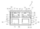
- the panel adapter 13 includes a housing 27 fixed to the turntable 11, a panel support 33 for supporting the loaded first panel P1, and a support plate 39 of the panel support 33.
- the first panel (P1) is installed in the first support pillar (42) holding the c), the case 45 provided in the lower portion of the housing 27 and placed on the panel support device (33) through the first support pillar (42).
- a panel posture adjusting device 47 for adjusting the posture of the panel, and a first panel fixing device 37 installed on the supporting plate 39 to fix the loaded first panel P1.
- a second panel fixing device 62 may be installed on the housing 27.
- the second panel fixing device 62 may be installed in the inversion frame 74, and the top and bottom surfaces of the inversion frame 74 may be inverted by the inversion device 77.
- the panel support device 33, the panel posture adjusting device 47, and the second panel fixing device 62 are shown installed in one housing 27, but the number of installation thereof is limited to those shown. It can be changed in various ways.
- the housing 27 includes a panel support 33, a vacuum chamber 28 in which the first panel fixing device 37 for fixing the first panel P1 is accommodated, and an entrance 29 connected to the vacuum chamber 28.
- Has The doorway 29 is provided on the upper surface of the housing 27 to open to the outside.
- the packing 30 is provided around the entrance 29 of the upper surface of the housing 27. The packing 30 allows the housing sealing device 15 to be sealed without a gap between the housing 27 and the housing sealing device 15 when the housing 27 covers the housing 27.
- the bottom surface of the housing 27 is provided with a plurality of through holes 31 through which the first and second support pillars 42 and 43 pass.
- the panel support device 33 has a shape corresponding to the shape of the second panel P2 in order to support the first panel P1 and adhere to the shape of the second panel P2.
- a pedestal 36 supporting the panel pressing member 34 and having a shape corresponding to the shape of the second panel, a second support pillar 43 positioned below the pedestal 36 and supporting the pedestal 36.
- a plurality of first panel fixing devices for fixing the second lifting device 48-2 for moving only the pedestal 36 and the panel pressing member 34 up and down through the support column 43, and the first panel P1 ( 37), the plurality of panel fasteners 38 installed on each of the plurality of first panel fixing devices 37 to fix the first panel P1, and the first panel P1 to be positioned at a predetermined height.
- a support plate 39 supporting the panel P1 a first elevating device 48-1 installed below the first panel fixing device 37 to move only the first panel fixing device 37 up and down, and a support play.
- the first position adjusting device 50 for adjusting the position of the groove 39
- the second position adjusting device 51 for adjusting the position of the panel pressing member 34
- the first panel fixing device 37 and the panel pressing member and the first panel fixing device 37 and the panel pressing member.
- a third elevating device 48-3 which moves 34 up and down at once.
- the panel pressing member 34 is made of a material that can be elastically extruded when subjected to pressing force in the thickness direction, such as rubber, silicone, or sponge. Accordingly, the panel pressing member 34 on which the first panel P1 is placed is made of the elastic material as described above, and the first panel P1 or the second panel P2 is pressed even when inclined to either side. When pressed, the panel pressing member 34 may be elastically compressed so that the first panel P1 and the second panel P2 may be in close contact with each other to be precisely bonded.
- the first panel fixing device 37 is installed on the support plate 39, and for example, a pair of first panel fixing devices 37 is installed per one first panel P1.
- the first panel P1 has a flexible property, and the first panel fixing device 37 fixes both sides of the flexible first panel P1, respectively.
- a panel fastener 38 may be formed at an upper portion to fix both sides of the first panel P1. That is, the first panel P1 may be fixed by the first panel fixing device 37 even without the panel pressing member 34.
- first support column 42 passes through the through hole 31 provided in the bottom surface of the housing 27 to connect the support plate 39 therein with the first position adjusting device 50.
- second support column 43 passes through the through hole formed in the support plate 39 and the through hole 31 provided in the bottom surface of the housing 27 to move the pedestal 36 to the second lifting device 48-. 2) or the second position adjusting device (51).
- the width of the through hole formed in the support plate 39 is greater than the width of the second support column 43
- the width of the through hole 31 formed in the housing 27 is the first and second support columns 42,. Larger than the width of 43, the first and second support pillars 42 and 43 may move to some extent in the through holes, respectively.
- the flexible tube 44 is for preventing air from entering the vacuum chamber 28 inside the housing 27 through the through hole 31.
- the flexible tube 44 prevents air from passing through the panel posture adjusting device 47. It is made of a structure or material capable of correspondingly contracting or stretching.
- One end of the flexible tube 44 is fixed to the lower surface of the housing 27 to cover the through hole 31, and the other end of the flexible tube 44 is the first position adjusting device 50 or the second lifting device ( 48-2) or may be fixed to an upper surface of the second position adjusting device 51.
- the first lifting device 48-1 is shown installed in the vacuum chamber 28 in the drawing, the first lifting device 48-1 has a first support pillar 42 and a lower portion of the vacuum chamber 28. It may be connected and installed.
- the panel posture adjusting device 47 is controlled by the controller 17, and can adjust the posture of the panel pressing member 34 and the first panel P1 through the first and second support pillars 42 and 43. have.
- the controller 17 detects the posture of the first panel P1 and the second panel P2 and the panel pressing member 34 loaded on the panel combiner 13 through the vision device 14,
- the panel posture adjusting device 47 is controlled so that the postures of the panel P1 and the second panel P2 and the panel pressing member 34 coincide with each other.
- the control device 17 detects the position of the first panel P1 through the first inspection camera 24 included in the vision device 14, and the second inspection camera 25 detects the position of the second panel P2. The position is detected, and the third inspection camera 26 detects the position of the pedestal 36 or the panel pressing member 34. Accordingly, the first panel P1 and the panel pressing member 34 detected by the first and third inspection cameras 24 and 26 based on the position of the second panel P2 detected by the second inspection camera 25. ) To adjust the position.
- the adjusting device 50 moves the first moving device 53 and the supporting plate 39 to move the supporting plate 39 in a first direction parallel to the ground (for example, in the longitudinal direction of the first panel P1).
- a rotating shaft in which the second moving device 54 and the support plate 39 which move in a second direction parallel to the ground and intersect the first direction (for example, the width direction of the first panel P1) and the support plate 39 are perpendicular to the ground It may include a rotary device 55 for rotating around.
- the first direction in which the first moving device 53 moves the supporting plate 39 or the second direction in which the second moving device 54 moves the supporting plate 39 is the length of the first panel P1. It is not limited to the direction or the width direction, it can be a variety of directions parallel to the ground and intersect each other.
- the second positioning device 51 is a first moving device 56 for moving the pedestal 36 in the first direction parallel to the ground, like the first positioning device 50, the pedestal parallel to the ground and It may include a second moving device 57 for moving in a second direction crossing the first direction and a rotating device 58 for rotating the pedestal 36 about a rotation axis disposed perpendicular to the ground.
- the height of the first panel P1 and the height of the panel pressing member 34 may need to be adjusted.
- the first elevating device 48-1 capable of moving only the first panel fixing device 37 up and down, and the second elevating device 48 capable of moving only the panel pressing member 34 up and down. -2) is provided.
- the first elevating device 48-1 and the second elevating device 48-2 may be provided with only one of them, or both. Therefore, when it is necessary to adjust the height of the first panel P1 and the panel pressing member 34, either or both of the first elevating device 48-1 and the second elevating device 48-2. Is operated to adjust the heights of the first panel P1 and the panel pressing member 34.
- the above-described position adjustment and height adjustment of the first panel P1 and the panel pressing member 34 may be performed first.
- the first panel fixing device ( 37 and the panel pressing member 34 are simultaneously raised to bond the first panel P1 to the second panel P2.
- the second panel fixing device 62 is installed on the inversion frame 74 disposed higher than the panel support device 33 in the vacuum chamber 28 and loaded on the panel adapter 13. 2 Secure the panel (P2).
- the second panel fixing device 62 includes a panel seating member 63 having a flat panel seating surface 64 on which the second panel P2 is placed, and a first stopper 65 in contact with the side surface of the second panel P2. And pressing the second stopper 66, the first pressing device 67 for pressing the second panel P2 toward the first stopper 65, and the second panel P2 for pressing the second stopper 66 toward the second stopper 66.
- the second pressurizing device 70 is included.
- the first stopper 65 is disposed perpendicular to the panel seating member 63 so as to be in contact with one side surface of the second panel P2, and the second stopper 66 is disposed on the first stopper of the second panel P2.
- the first stopper 65 is spaced apart from the panel mounting member 63 so as to be in contact with the side perpendicular to the side contacting the surface 65).
- the height protruding from the panel seating member 63 of the first and second stoppers 65 and 66 may be lower than the thickness of the second panel P2 placed on the panel seating member 63.
- the first stopper 65 and the second stopper 66 may be made of various materials that can prevent the damage of the second panel P2 when the second panel P2 such as plastic or rubber is in close contact with each other.
- the first pressing device 67 is for pressing the second panel P2 placed on the panel seating surface 64 of the panel seating member 63 toward the first stopper 65.
- the first pressing device 67 provides a moving force to the first pressing member 68 and the first pressing member 68 for pressing the second panel P2 in contact with one edge of the second panel P2.
- a first pressurized actuator 69 for the purpose.
- the first pressing member 68 may be made of various materials that can prevent damage to the second panel P2 when the first pressing member 68 is in close contact with the second panel P2 such as plastic or rubber.
- the second pressing device 70 is for pressing the second panel P2 placed on the panel seating surface 64 toward the second stopper 66, and the specific structure is the same as that of the first pressing device 67.
- the second pressurizing device 70 includes a second pressurizing member 71 and a second pressurizing actuator 72 for moving the second pressurizing member 71.
- the specific structure of the first pressing device 67 or the second pressing device 70 may be variously changed.
- the second panel fixing device 62 as shown in the structure having a pair of stoppers (65, 66) and a pair of pressurizing devices (67) 70, means for generating a suction force (intake, Air flow passages, suction force generators, etc.), or various other structures such as other adsorption or other mechanisms capable of fixing the second panel P2 placed on the panel seating surface 64.
- the second panel fixing device 62 has a structure that fixes the second panel P2 using vacuum pressure (suction input)
- the vacuum pressure of the second panel fixing device 62 is fixed to the second panel. It should be above the vacuum pressure provided to the vacuum chamber 28 of the housing 27 in which the device 62 is housed.
- the inversion frame 74 is installed in the vacuum chamber 28 so that its upper and lower surfaces can be reversed.
- Lever 75 is coupled to both ends of the inversion frame 74, one lever 75 is coupled to the rotary shaft 78 of the inverter 77, the other lever 75 to the housing 27
- the support shaft 79 coupled to the is coupled.
- the rotary shaft 78 and the support shaft 79 are on the same line, and the inverted frame 74 is rotated by 180 degrees with the rotary shaft 78 and the support shaft 79 as the center of rotation so that the upper and lower surfaces thereof can be reversed.
- the reversing device 77 is disposed outside the housing 27 except for a part of the rotation shaft 78 such as a drive unit in which friction occurs during operation.
- the inversion frame fixing device 80 is installed in the housing 27 to fix the inversion frame 74 in its inverted state.
- the inversion frame fixing device 80 is a fixing protrusion 81 inserted into the fixing hole 76 provided on the side of the inverting frame 74 and a fixing installed in the housing 27 to advance the fixing protrusion 81.
- a projection retraction device 82 is installed outside the housing 27, and the fixing protrusion 81 penetrates the housing 27, and an end thereof is positioned in the vacuum chamber 28.
- fixing holes 76 are provided at both ends of the inversion frame 74, and a pair of inversion frame fixing devices 80 fixes the inversion frame 74.
- the installation number of 80 may be variously changed.
- the specific configuration of the inversion frame fixing device 80 may be changed to various other structures that can stably hold the inverted inversion frame 74.
- the housing sealing apparatus 15 is in close contact with the housing 27 and the sealing cover 84 for opening and closing the doorway 29, and the sealing cover 84 for opening and closing the doorway 29. It may include a sealing cover moving device 85 for moving the sealing cover 84 to be able to.
- the hermetic cover moving device 85 is coupled to the fixing base 86 which is disposed higher than the panel bonding machine 13 in the panel bonding zone Z4.
- the hermetic cover 84 is installed on the holder 86 so as to be movable up and down by a guide bar 87 which is slidably coupled to the hermetic cover moving device 85 and the holder 86.
- the sealing cover moving device 85 moves the sealing cover 84 downward, the sealing cover 84 is stably lowered while being supported by the guide bar 87 to seal the entrance 29 of the housing 27. can do.
- the sealing cover 84 is coupled to the vacuum tube 88 is connected to the vacuum generator 16. By operating the vacuum pressure generator 16 in a state where the sealing cover 84 seals the entrance 29 of the housing 27, forcibly discharging the air inside the vacuum chamber 28 through the vacuum tube 88.
- the vacuum chamber 28 can be brought to a vacuum state.
- the moving structure of the sealed cover moving device 85 or the sealed cover 84 is not limited to that shown and can be variously changed.
- a packing 30 for sealing between the housing 27 and the sealing cover 84 may be provided in the sealing cover 84.
- the vacuum tube 88 connected to the vacuum generator 16 to provide a vacuum pressure to the vacuum chamber 28 may be connected to the housing 27 instead of the sealing cover 84.
- the present invention may be bonded to the panel by using the above-described panel bonding machine alone in addition to the turntable structure as described above.
- the vision device, the housing sealing device, and the like, which are necessary for the panel bonding may be appropriately disposed around the panel bonding machine.
Abstract
A curved panel bonding unit and a curved panel bonding apparatus comprising the same are disclosed. A curved panel bonding unit according to the present invention comprises: a housing having a vacuum chamber and an entrance open to the outside; a panel pressing member installed in the vacuum chamber; a first panel fixing device provided with a fixing means for fixing a first panel and which is installed in the vacuum chamber; at least one first support column for supporting the first panel fixing device through at least one of a plurality of through holes provided on the bottom surface of the housing; at least one second support column for supporting the panel pressing member through at least one of the plurality of through holes provided on the bottom surface of the housing; an inverting frame which is disposed in the vacuum chamber higher than the panel pressing member and has a second panel fixing device for fixing a second panel for bonding the same to the first panel; an inverting device for inverting the upper and lower surfaces of the inverting frame so that one surface of the second panel fixed to the second panel fixing device faces the first panel; and an elevating device for raising or lowering the first panel fixing device and the panel pressing member at the same time.
Description
본 발명은 곡면패널 합착유닛과 이를 포함하는 곡면패널 합착장치에 관한 것으로, 더욱 상세하게는 곡면패널에 다른 패널을 정밀하고도 신속하게 합착할 수 있는 곡면패널 합착유닛과 이를 포함하는 곡면패널 합착장치에 관한 것이다.The present invention relates to a curved panel bonding unit and a curved panel bonding apparatus including the same, and more particularly, to a curved panel bonding unit capable of precisely and quickly bonding other panels to the curved panel and a curved panel bonding apparatus including the same It is about.
휴대폰, 스마트폰, 디지털 TV, PC, 노트북, PDA, 내비게이션 등 다양한 디지털 기기가 출시되면서 평판 표시 장치나 터치 패널 등의 패널제품의 수요가 증가하고 있다.As various digital devices such as mobile phones, smartphones, digital TVs, PCs, laptops, PDAs, and navigations are released, demand for panel products such as flat panel displays and touch panels is increasing.
평판 표시 장치에는 액정 표시 장치(LCD, liquid crystal display), 플라즈마 표시 장치(PDP, plasma display device), 유기 발광 다이오드(OLED, organic light emitting diode) 등이 있다. 액정 표시 장치의 경우, 경량, 박형, 저전력구동, 풀-컬러, 고해상도 구현 등의 특징으로 인해 각종 디지털 기기의 디스플레이 장치로 널리 사용되고 있다.The flat panel display includes a liquid crystal display (LCD), a plasma display device (PDP), an organic light emitting diode (OLED), and the like. The liquid crystal display is widely used as a display device of various digital devices due to features such as light weight, thinness, low power driving, full color, and high resolution.
액정 표시 장치는 광의 투과율을 제어하는 액정 표시 패널에 편광판과 백라이트 유닛을 합착하여 제조한다. 플라즈마 표시 장치는 서로 대향하는 두 패널에 서로 교차하는 전극을 배열하여 제조한다. 이러한 액정 표시 장치나 플라즈마 표시 장치를 비롯하여 각종 평판 표시 장치는 평판 표시 패널에 투명 보호판 등 다양한 기능의 패널을 합착하여 제조한다.The liquid crystal display device is manufactured by bonding a polarizing plate and a backlight unit to a liquid crystal display panel that controls light transmittance. The plasma display device is manufactured by arranging electrodes crossing each other on two panels facing each other. Various flat panel display devices including such liquid crystal display devices and plasma display devices are manufactured by bonding a panel having various functions such as a transparent protective plate to a flat panel display panel.
터치 패널은 각종 평판 표시 장치의 표시 면에 설치되어 사용자가 표시 장치를 보면서 원하는 정보를 선택하도록 하는데 이용되는 입력장치이다. 터치 패널은 저항막 방식(resistive type), 정전용량 방식(capacitive type), 전기자기장형 방식(EM, electro-magnetic type), 소오 방식(saw type) 및 인프라레드 방식(infrared type) 등이 있다. 이러한 터치 패널은 투명한 재질의 윈도우 패널에 투명한 도전성 전극 패널을 합착하여 제조한다.The touch panel is an input device installed on the display surfaces of various flat panel display devices and used to allow a user to select desired information while viewing the display device. The touch panel includes a resistive type, a capacitive type, an electro-magnetic type (EM), a saw type and an infrared type. The touch panel is manufactured by bonding a transparent conductive electrode panel to a window panel made of a transparent material.
최근에는 곡면 형상을 가지는 패널을 포함하는 스마트폰이나 TV 등의 제품들이 다수 출시되고 있는데, 종래의 장치 및 방법(일례로 대한민국 공개특허 제10-2016-0015570호)으로는 곡면패널을 포함하는 둘 이상의 패널을 합착하는 것이 쉽지 않은 문제가 있다.Recently, a number of products such as smart phones and TVs including a panel having a curved shape have been released. Conventional devices and methods (for example, Korean Patent Laid-Open Publication No. 10-2016-0015570) include two including a curved panel. There is a problem that it is not easy to bond the above panels.
본 발명의 목적은, 곡면패널에 다른 패널을 정밀하면서도 신속하게 합착시킬 수 있는 곡면패널 합착유닛 및 이를 포함하는 곡면패널 합착장치를 제공하는 것에 있다.Disclosure of Invention An object of the present invention is to provide a curved panel bonding unit and a curved panel bonding apparatus including the same, which can accurately and quickly bond other panels to the curved panel.
상술한 목적을 달성하기 위하여 본 발명은 곡면패널 합착유닛 및 이를 포함하는 곡면패널 합착장치를 제공하는데, 본 발명의 일례에 따른 곡면패널 합착유닛은, 진공 챔버와 외부로 개방된 출입구를 갖는 하우징; 상기 진공 챔버에 설치되는 패널 가압부재; 제1 패널을 고정하기 위한 고정수단이 구비되고, 상기 진공 챔버에 설치되는 제1 패널 고정장치; 상기 하우징의 바닥면에 마련되는 복수의 관통구멍 중 어느 하나 이상을 통과하여 상기 제1 패널 고정장치를 지지하는 하나 이상의 제1 지지기둥; 상기 하우징의 바닥면에 마련되는 복수의 관통구멍 중 어느 하나 이상을 통과하여 상기 패널 가압부재를 지지하는 하나 이상의 제2 지지기둥; 상기 진공 챔버에 상기 패널 가압부재보다 높게 배치되고, 상기 제1 패널과 합착하기 위한 제2 패널을 고정하는 제2 패널 고정장치가 구비된 반전프레임; 상기 제2 패널 고정장치에 고정된 상기 제2 패널의 일면이 상기 제1 패널을 향하도록 상기 반전 프레임의 상하면을 반전시키는 반전장치; 및 상기 제1 패널고정장치와 상기 패널 가압부재를 동시에 상승 또는 하강시키는 승강장치를 포함하여 이루어진다.In order to achieve the above object, the present invention provides a curved panel bonding unit and a curved panel bonding apparatus including the same, the curved panel bonding unit according to one embodiment of the present invention comprises: a housing having a vacuum chamber and an entrance opening to the outside; A panel pressing member installed in the vacuum chamber; A first panel fixing device provided with fixing means for fixing the first panel and installed in the vacuum chamber; At least one first support column passing through any one or more of a plurality of through holes provided in the bottom surface of the housing to support the first panel fixing device; At least one second support column passing through any one or more of a plurality of through holes provided in the bottom surface of the housing to support the panel pressing member; An inversion frame disposed in the vacuum chamber than the panel pressurizing member and having a second panel fixing device configured to fix a second panel for attaching to the first panel; An inversion device for inverting an upper and lower surfaces of the inversion frame such that one surface of the second panel fixed to the second panel fixing device faces the first panel; And an elevating device for simultaneously raising or lowering the first panel fixing device and the panel pressing member.
또한 상기 제1 패널의 높이를 조절하기 위하여 상기 제1 패널 고정장치를 상승 또는 하강시키는 승강장치; 및 상기 패널 가압부재의 높이를 조절하기 위하여 상기 패널 가압부재를 상승 또는 하강시키는 승강장치 중에서 적어도 하나를 더 포함할 수 있다.In addition, the lifting device for raising or lowering the first panel fixing device to adjust the height of the first panel; And an elevating device for raising or lowering the panel pressing member to adjust the height of the panel pressing member.
또한 상기 제1 지지기둥을 통해 상기 제1 패널 고정장치를 지면과 평행한 제1 방향 및 지면과 평행하고 상기 제1 방향과 교차하는 제2 방향으로 이동시키고, 상기 제1 패널 고정장치를 지면과 수직으로 배치된 회전축을 중심으로 회전시키는 제1 위치조절장치를 더 포함할 수 있다. In addition, the first panel fixing device moves the first panel fixing device in a first direction parallel to the ground and in a second direction parallel to the ground and intersects the first direction, and moves the first panel fixing device to the ground. It may further include a first position adjusting device for rotating about a vertically arranged rotation axis.
또한 상기 제2 지지기둥을 통해 상기 패널 가압부재를 지면과 평행한 제1 방향 및 지면과 평행하고 상기 제1 방향과 교차하는 제2 방향으로 이동시키고, 상기 패널 가압부재를 지면과 수직으로 배치된 회전축을 중심으로 회전시키는 제2 위치조절장치를 더 포함할 수 있다. In addition, the panel pressing member is moved in a first direction parallel to the ground and in a second direction parallel to the ground and intersecting the first direction through the second support pillar, and the panel pressing member is disposed perpendicular to the ground. It may further include a second position adjusting device for rotating around the rotation axis.
상기 제1 패널은 플랙시블한 성질을 가지는 패널일 수 있으며, 상기 제2 패널은 일부 또는 전부가 곡면 형상을 가지는 곡면패널일 수 있다. The first panel may be a panel having a flexible property, and the second panel may be a curved panel having some or all curved surfaces thereof.
상기 패널 가압부재는 가압력을 받을 때 탄력적으로 압축되는 소재로 이루어질 수 있다. The panel pressing member may be made of a material that is elastically compressed when subjected to a pressing force.
또한 본 발명의 일례에 의한 곡면패널 합착유닛은, 상기 제1 패널 고정장치를 지지하고, 하부에 상기 제1 지지기둥이 연결된 지지 플레이트; 및 상기 제1 패널 고정장치의 상부에 형성되고, 상기 제1 패널을 고정하기 위해 조이는 하나 이상의 패널 조임부를 더 포함할 수 있다.In addition, the curved panel bonding unit according to an embodiment of the present invention, the support plate for supporting the first panel fixing device, the support plate connected to the first support pillar in the lower portion; And one or more panel fasteners formed on an upper portion of the first panel fixing device and tightened to fix the first panel.
또한 상기 복수의 관통구멍을 통해 상기 진공 챔버 내부로 공기가 유입되는 것을 방지하기 위해 상기 하우징 외부에 노출된 제1 및 제2 지지기둥을 감싸는 가요성 튜브를 더 포함할 수 있다.The apparatus may further include a flexible tube surrounding the first and second support pillars exposed to the outside of the housing to prevent air from flowing into the vacuum chamber through the plurality of through holes.
또한 본 발명은 곡면패널 합착장치를 제공하는데, 본 발명의 일례에 의한 곡면패널 합착장치는, In addition, the present invention provides a curved panel bonding apparatus, the curved panel bonding apparatus according to an example of the present invention,
진공 챔버와 외부로 개방된 출입구를 갖는 하우징을 구비하고, 상기 진공 챔버 내에서 제1 패널과 제2 패널을 각각의 일면이 마주한 상태로 합착하기 위한 복수의 패널 합착기; 상기 복수의 패널 합착기가 장착되는 턴테이블; 상기 턴테이블에 장착된 상기 복수의 패널 합착기를 상기 턴테이블 상의 회전 경로를 따라 이송시키기 위해 상기 턴테이블을 간헐적으로 회전시키는 턴테이블 회전장치; 상기 회전 경로 중에 마련되는 패널 합착 존에 설치되고, 상기 복수의 패널 합착기 중에서 상기 패널 합착 존에 정지한 패널 합착기의 하우징에 밀착되어 그 출입구를 밀폐하기 위한 밀폐 커버와, 상기 밀폐 커버를 이동시키기 위한 밀폐 커버 이동장치를 갖는 하우징 밀폐장치; 상기 복수의 패널 합착기 중에서 상기 하우징 밀폐장치에 의해 그 출입구가 밀폐된 패널 합착기의 진공 챔버에 진공압을 제공하기 위한 진공압 발생장치; 및 장치의 전반적인 동작을 제어하기 위한 제어장치를 포함하고,A plurality of panel adapters including a housing having a vacuum chamber and an entrance opening to the outside, the plurality of panel adapters for bonding the first panel and the second panel to each other in a state in which the first panel and the second panel face each other; A turntable on which the plurality of panel joiners are mounted; A turntable rotating device intermittently rotating the turntable to transfer the plurality of panel joiners mounted on the turntable along a rotation path on the turntable; A sealing cover installed in a panel bonding zone provided in the rotation path and being in close contact with a housing of the panel bonding machine stopped in the panel bonding zone among the plurality of panel bonding machines to seal the entrance and exit; A housing closure device having a closure cover moving device for making it secure; A vacuum pressure generator for providing a vacuum pressure to the vacuum chamber of the panel adapter in which the entrance and exit of the plurality of panel adapters are sealed by the housing closure device; And a control device for controlling the overall operation of the device,
상기 패널 합착기는, 상기 진공 챔버에 설치되는 패널 가압부재; 제1 패널을 고정하기 위한 고정수단이 구비되고, 상기 진공 챔버에 설치되는 제1 패널 고정장치; 상기 하우징의 바닥면에 마련되는 복수의 관통구멍 중 어느 하나 이상을 통과하여 상기 제1 패널 고정장치를 지지하는 하나 이상의 제1 지지기둥; 상기 하우징의 바닥면에 마련되는 복수의 관통구멍 중 어느 하나 이상을 통과하여 상기 패널 가압부재를 지지하는 하나 이상의 제2 지지기둥; 상기 진공 챔버에 상기 패널 가압부재보다 높게 배치되고, 상기 제1 패널과 합착하기 위한 제2 패널을 고정하는 제2 패널 고정장치가 구비된 반전프레임; 상기 제2 패널 고정장치에 고정된 상기 제2 패널의 일면이 상기 제1 패널을 향하도록 상기 반전 프레임의 상하면을 반전시키는 반전장치; 및 상기 제1 패널고정장치와 상기 패널 가압부재를 동시에 상승 또는 하강시키는 승강장치를 포함하여 이루어진다.The panel joining unit may include a panel pressing member installed in the vacuum chamber; A first panel fixing device provided with fixing means for fixing the first panel and installed in the vacuum chamber; At least one first support column passing through any one or more of a plurality of through holes provided in the bottom surface of the housing to support the first panel fixing device; At least one second support column passing through any one or more of a plurality of through holes provided in the bottom surface of the housing to support the panel pressing member; An inversion frame disposed in the vacuum chamber than the panel pressurizing member and having a second panel fixing device configured to fix a second panel for attaching to the first panel; An inversion device for inverting an upper and lower surfaces of the inversion frame such that one surface of the second panel fixed to the second panel fixing device faces the first panel; And an elevating device for simultaneously raising or lowering the first panel fixing device and the panel pressing member.
또한 상기 제1 패널의 높이를 조절하기 위하여 제1 패널 고정장치를 상승 또는 하강시키는 승강장치; 및 상기 패널 가압부재의 높이를 조절하기 위하여 상기 패널 가압부재를 상승 또는 하강시키는 승강장치 중에서 적어도 하나를 더 포함할 수 있다.In addition, the lifting device for raising or lowering the first panel fixing device to adjust the height of the first panel; And an elevating device for raising or lowering the panel pressing member to adjust the height of the panel pressing member.
또한 본 발명의 일례에 의한 곡면패널 합착장치는, 상기 제1 지지기둥을 통해 상기 제1 패널 고정장치를 지면과 평행한 제1 방향 및 지면과 평행하고 상기 제1 방향과 교차하는 제2 방향으로 이동시키고, 상기 제1 패널 고정장치를 지면과 수직으로 배치된 회전축을 중심으로 회전시키는 제1 위치조절장치; 및 상기 제2 지지기둥을 통해 상기 패널 가압부재를 지면과 평행한 제1 방향 및 지면과 평행하고 상기 제1 방향과 교차하는 제2 방향으로 이동시키고, 상기 패널 가압부재를 지면과 수직으로 배치된 회전축을 중심으로 회전시키는 제2 위치조절장치를 더 포함할 수 있다.In addition, the curved panel bonding apparatus according to an embodiment of the present invention, the first panel fixing device in the first direction parallel to the ground and the second direction parallel to the ground and intersect the first direction through the first support pillar A first position adjusting device which moves and rotates the first panel fixing device about a rotation axis disposed perpendicular to the ground; And moving the panel pressurizing member in a first direction parallel to the ground and in a second direction parallel to the ground and intersecting the first direction through the second support pillar, wherein the panel pressurizing member is disposed perpendicular to the ground. It may further include a second position adjusting device for rotating around the rotation axis.
또한 상기 회전 경로 중에 상기 패널 합착 존 또는 상기 패널 합착 존 보다 상류에 마련되는 촬영 존에 설치되고, 상기 패널 가압부재, 상기 제1 패널 및 상기 제2 패널의 자세를 검출하고, 그 검출 신호를 상기 제어장치에 제공하는 비전장치를 더 포함하고, 상기 제어장치는 상기 비전장치로부터 검출 신호를 제공받아 상기 제1 위치조절장치 및 제2 위치조절장치를 통하여 상기 제1 패널 및 패널 가압부재의 위치를 조절한 다음, 상기 패널 합착 존에서 상기 제1 패널과 상기 제2 패널을 합착시킬 수 있다.Further, it is provided in the photographing zone provided upstream of the panel bonding zone or the panel bonding zone in the rotation path, and detects the attitude of the panel pressing member, the first panel, and the second panel, and detects the detection signal. The apparatus further includes a vision device provided to the control device, wherein the control device receives a detection signal from the vision device to adjust the position of the first panel and the panel pressing member through the first position adjusting device and the second position adjusting device. After adjustment, the first panel and the second panel may be bonded in the panel bonding zone.
상술한 본 발명에 의할 경우, 각 패널의 위치를 세밀하게 조절한 다음 곡면패널의 형상에 맞게 합착할 수 있어, 정밀하면서도 신속하게 둘 이상의 패널을 합착할 수 있다. According to the present invention described above, the position of each panel can be finely adjusted and then bonded to suit the shape of the curved panel, so that two or more panels can be bonded precisely and quickly.
또한, 본 발명에 의한 곡면패널 합착장치는 복수의 패널 합착기가 회전하는 턴테이블에 장착되어 턴테이블 상에 마련되는 회전 경로를 따라 이동하면서 합착작업을 수행하기 때문에, 콤팩트한 구조를 구현할 수 있으며, 합착 작업의 효율을 향상시킬 수 있다.In addition, the curved panel bonding apparatus according to the present invention is mounted on the turntable rotating the plurality of panel combiner to perform the bonding operation while moving along the rotation path provided on the turntable, it is possible to implement a compact structure, the bonding operation Can improve the efficiency.
도 1은 본 발명의 일 실시예에 따른 곡면패널 합착장치를 도시한 도면이다.1 is a view showing a curved panel bonding apparatus according to an embodiment of the present invention.
도 2는 본 발명의 일 실시예에 따른 곡면패널 합착유닛을 도시한 평면도이다.Figure 2 is a plan view showing a curved panel bonding unit according to an embodiment of the present invention.
도 3은 본 발명의 일 실시예에 따른 곡면패널 합착유닛을 도시한 단면도이다.3 is a cross-sectional view showing a curved panel bonding unit according to an embodiment of the present invention.
<부호의 설명><Description of the code>
10: 곡면패널 합착장치10: curved panel bonding device
11: 턴테이블 11: turntable
12: 턴테이블 회전장치12: turntable rotator
13: 패널 합착기 13: panel adapter
14: 비전장치14: Vision device
15: 하우징 밀폐장치 15: housing seal
16: 진공압 발생장치16: vacuum pressure generator
17: 제어장치 17: controller
18: 플라즈마 처리장치18: plasma processing apparatus
19: 패널안착판 19: Panel seat plate
20: 작업 테이블20: working table
21: 플라즈마 처리기 21: plasma processor
24 ~ 26 : 제1 ~ 3 검사 카메라24 to 26: first to third inspection camera
27: 하우징 27: housing
28: 진공 챔버28: vacuum chamber
29: 출입구 29: doorway
30: 패킹30: Packing
31: 관통구멍 31: through hole
33: 패널 받침장치33: panel support
34: 패널 가압부재 34: panel pressing member
36: 받침대36: pedestal
37: 제1 패널 고정장치 37: first panel fixing device
38: 패널 조임부38: panel fasteners
39: 지지 플레이트 39: support plate
42: 제1 지지기둥42: first support pillar
43: 제2 지지기둥 43: second support pillar
44: 가요성 튜브44: flexible tube
45: 케이스 45: case
47: 패널 자세조절장치47: Panel posture adjustment device
48: 승강장치 48: lifting device
48-1: 제1 승강장치48-1: First lifting device
48-2: 제2 승강장치 48-2: second lifting device
48-3: 제3 승강장치48-3: third lifting device
50: 제1 위치조절장치 50: first position adjusting device
51: 제2 위치조절장치51: second position adjusting device
53, 56: 제1 이동장치 53, 56: first mobile device
54, 57: 제2 이동장치54, 57: second mobile device
55, 58: 회전장치55, 58: rotating device
62: 제2 패널 고정장치 62: second panel fixing device
63: 패널 안착부재63: panel mounting member
64: 패널 안착면64: panel seating surface
65, 66 : 제1, 2 스토퍼 65, 66: 1st, 2nd stopper
67, 70 : 제1, 2 가압장치67, 70: first and second pressurizing device
68, 71 : 제1, 2 가압부재 68, 71: first and second pressing members
69, 72 : 제1, 2 가압 액츄에이터69, 72: 1st, 2nd pressurized actuator
74: 반전 플레이트 74: inversion plate
75: 레버75: lever
76: 고정구멍 76: fixing hole
77: 반전장치77: inverter
78: 회전축 78: axis of rotation
79: 지지축79: support shaft
80: 반전 프레임 고정장치 80: reverse frame holder
81: 고정돌기81: fixing protrusion
82: 고정돌기 진퇴장치 82: fixed protrusion retraction device
84: 밀폐 커버84: airtight cover
85: 밀폐 커버 이동장치 85: sealed cover shifter
86: 고정대86: holder
87: 가이드 바 87: guide bar
88: 진공 튜브88: vacuum tube
Z1 ~ Z4: 작업존Z1 to Z4: Work Zone
본 발명을 설명함에 있어서, 도면에 도시된 구성요소의 크기나 형상 등은 설명의 명료성과 편의를 위해 과장되거나 단순화되어 나타날 수 있다. 또한, 본 발명의 구성 및 작용을 고려하여 특별히 정의된 용어들은 사용자, 운용자의 의도 또는 관계에 따라 달라질 수 있다. 이러한 용어들은 본 명세서 전반에 걸친 내용을 토대로 본 발명의 기술적 사상에 부합하는 의미와 개념으로 해석되어야 한다.In describing the present invention, the size or shape of the components shown in the drawings may be exaggerated or simplified for clarity and convenience of description. In addition, terms that are specifically defined in consideration of the configuration and operation of the present invention may vary depending on the intention or relationship of the user or operator. These terms should be interpreted as meanings and concepts corresponding to the technical spirit of the present invention based on the contents throughout the specification.
명세서 전체에서, 어떤 부분이 다른 부분과 "연결"되어 있다고 할 때, 이는 "직접적으로 연결"되어 있는 경우뿐 아니라, 그 중간에 다른 부재를 사이에 두고 "간접적으로 연결"되어 있는 경우도 포함한다. 또한 어떤 부분이 어떤 구성요소를 "포함"한다고 할 때, 이는 특별히 반대되는 기재가 없는 한 다른 구성요소를 제외하는 것이 아니라 다른 구성요소를 더 구비할 수 있다는 것을 의미한다.Throughout the specification, when a part is "connected" to another part, it includes not only "directly connected" but also "indirectly connected" with another member in between. . In addition, when a part is said to "include" a certain component, this means that it may further include other components, without excluding the other components unless otherwise stated.
이하 본 발명의 바람직한 실시예에 대하여 첨부된 도면을 참조하여 보다 구체적으로 설명한다.Hereinafter, exemplary embodiments of the present invention will be described in detail with reference to the accompanying drawings.
도 1은 본 발명의 일 실시예에 따른 곡면패널 합착장치를 도시한 도면이다.1 is a view showing a curved panel bonding apparatus according to an embodiment of the present invention.
도 1을 참조하면, 본 발명의 일 실시예에 따른 곡면패널 합착장치(10)는, 턴테이블(11), 복수의 패널 합착기(13), 비전장치(14), 하우징 밀폐장치(15), 진공압 발생장치(16), 제어장치(17)를 포함한다.Referring to FIG. 1, the curved panel bonding apparatus 10 according to the embodiment of the present invention includes a turntable 11, a plurality of panel bonding machines 13, a vision device 14, a housing sealing device 15, And a vacuum generator 16 and a controller 17.
본 실시예에 따른 곡면패널 합착장치(10)는 두 개의 패널을 정밀하면서도 신속하게 서로 합착시키기 위한 것으로, 두 개의 패널 중 어느 하나의 일면에 OCA 등의 접착물질이 도포된 상태로 복수의 패널 합착기(13)에 로딩된다. 그리고 패널 합착기(13)는 두 개의 패널의 자세를 맞춰 이들을 자동으로 합착할 수 있다.The curved panel bonding device 10 according to the present embodiment is for bonding two panels together precisely and quickly, and bonding a plurality of panels in a state in which an adhesive material such as OCA is applied to one surface of two panels. Loaded into the machine 13. In addition, the panel combiner 13 may automatically combine the two panels in an attitude.
본 실시예에서 제1 패널(P1)은 플랙시블(flexible) 소재의 디스플레이 패널에 보호필름이 결합된 형태, 제2 패널(P2)은 유리 등을 포함하는 강성이 있는 소재로 이루어진 곡면패널인 것에 대해 설명하나, 각 패널이 상기와 같이 한정되는 것은 아니다. 제2 패널(P2)은 소정의 곡률을 가지고 전체가 곡률을 따라 휘어진 형상일 수 있고, 또는 제2 패널(P2)의 중앙 부분은 평평하고 모서리 부분이 소정의 곡률로 휘어진 형상일 수도 있다. 이러한 제2 패널(P2)의 형상은 필요에 따라 다양하게 변형될 수 있다.In the present embodiment, the first panel P1 is a form in which a protective film is coupled to a display panel made of a flexible material, and the second panel P2 is a curved panel made of a rigid material including glass. Although each panel is demonstrated, it is not limited as mentioned above. The second panel P2 may have a predetermined curvature and may be bent along the curvature, or the center portion of the second panel P2 may be flat and the corner portion may be bent at a predetermined curvature. The shape of the second panel P2 may be variously modified as necessary.
턴테이블(11)의 일 측에 플라즈마 처리장치(18)가 설치된다. 플라즈마 처리 장치는 제1 패널(P1) 또는 제2 패널(P2)의 표면을 처리하기 위해 구비되며, 플라즈마 처리장치(18)에서 접착물질이 도포되지 않은 면에 대한 표면처리가 이루어진다. 이를 위해 플라즈마 처리장치(18)는 복수의 패널안착판(19)이 구비된 작업 테이블(20) 및 플라즈마 처리기(21)를 포함한다. 복수의 패널안착판(19)은 제1 패널(P1) 또는 제2 패널(P2)이 안착되기 위해 구비된다.The plasma processing apparatus 18 is installed at one side of the turntable 11. The plasma processing apparatus is provided to treat the surface of the first panel P1 or the second panel P2, and the surface treatment is performed on the surface on which the adhesive material is not applied in the plasma processing apparatus 18. To this end, the plasma processing apparatus 18 includes a work table 20 equipped with a plurality of panel seating plates 19 and a plasma processor 21. The plurality of panel seating plates 19 are provided for mounting the first panel P1 or the second panel P2.
그에 따라 작업자는 플라즈마 처리장치(18)를 이용하여 제1 패널(P1)이나 제2 패널(P2)을 표면처리하고, 이를 패널 합착기(13)에 로딩하여 제1 패널(P1) 및 제2 패널(P2)의 합착 공정이 수행될 수 있다.Accordingly, the operator uses the plasma processing apparatus 18 to surface-treat the first panel P1 or the second panel P2, and loads the same on the panel combiner 13 to the first panel P1 and the second panel. The bonding process of the panel P2 may be performed.
본 실시예에 따른 곡면패널 합착장치(10)를 구성하는 다양한 장치들과 곡면패널 합착장치(10)의 전반적인 동작은 제어장치(17)에 의해 제어된다. 제어장치(17)는 턴테이블(11)을 간헐적으로 회전시켜 제1 패널(P1)과 제2 패널(P2)이 로딩된 패널 합착기(13)를 회전시킨다. 그에 따라 패널 합착기(13)는 턴테이블(11)의 회전에 의해 구비된 회전 경로(C)를 따라 이송된다. 이때, 회전 경로(C)에는 패널 합착기(13)가 정지하는 복수의 작업존(Z1 ~ Z4)이 마련되며, 패널 합착기(13)가 복수의 작업존(Z1 ~ Z4)을 차례로 통과하면서 패널 로딩, 패널 촬영, 패널 자세조절, 패널 합착 등의 작업이 연속적으로 수행된다.Various operations of the curved panel bonding apparatus 10 and the overall operation of the curved panel bonding apparatus 10 according to the present embodiment are controlled by the controller 17. The controller 17 rotates the turntable 11 intermittently to rotate the panel adapter 13 loaded with the first panel P1 and the second panel P2. Accordingly, the panel combiner 13 is conveyed along the rotation path C provided by the rotation of the turntable 11. At this time, the rotation path C is provided with a plurality of work zones Z1 to Z4 at which the panel adapter 13 stops, and the panel combiner 13 sequentially passes through the plurality of work zones Z1 to Z4. Panel loading, panel shooting, panel posture adjustment, panel fastening, etc. are performed continuously.
턴테이블(11)은 지면과 평행하게 놓이고, 지면과 수직인 축을 회전축으로 하여 회전된다. 턴테이블(11)은 턴테이블 회전장치(12)에 의해 회전된다. 즉, 도 1에 도시된 바와 같이, 턴테이블(11)에는 네 개의 패널 합착기(13)가 설치되며, 제어장치(17)는 턴테이블 회전장치(12)를 제어하여 턴테이블(11)을 90도씩 간헐적으로 회전시켜, 네 개의 패널 합착기(13)를 각 작업존(Z1 ~ Z4)에 위치시킨다.The turntable 11 is placed in parallel with the ground, and is rotated using an axis perpendicular to the ground as the rotation axis. The turntable 11 is rotated by the turntable rotating device 12. That is, as shown in FIG. 1, four panel adapters 13 are installed on the turntable 11, and the controller 17 controls the turntable rotating device 12 to intermittently turn the turntable 11 by 90 degrees. By rotating the four panel adapters 13 in each of the working zones Z1 to Z4.
제1 작업존(Z1)에서는 패널 합착기(13)에 제1 패널(P1)을 로딩하는 작업이 이루어지거나, 제1 패널(P1)과 제2 패널(P2)이 합착된 패널 조립체를 패널 합착기(13)에서 언로딩하는 작업이 이루어질 수 있다. 제2 작업존(Z2)에서는 제1 패널(P1) 또는 제2 패널(P2)을 로딩하는 작업이 이루어질 수 있다. 이때, 제1 패널(P1)이나 제2 패널(P2)을 패널 합착기(13)에 로딩하는 작업이나, 패널 조립체를 언로딩하는 작업은 작업자에 의해 수작업으로 이루질 수 있으며, 로딩 장치나 언로딩 장치에 의해 자동으로 이루어질 수도 있다.In the first working zone Z1, a panel assembly in which the first panel P1 is loaded in the panel joining machine 13 is performed, or a panel assembly in which the first panel P1 and the second panel P2 are bonded is panel-bonded. Unloading can be done in machine 13. The loading of the first panel P1 or the second panel P2 may be performed in the second working zone Z2. In this case, loading the first panel P1 or the second panel P2 into the panel combiner 13 or unloading the panel assembly may be performed manually by an operator. It can also be done automatically by the loading device.
제3 작업존(Z3)에서는 패널 합착기(13)에 로딩된 제1 패널(P1)과 제2 패널(P2)을 촬영하여 이들의 자세를 검출하고, 그 검출 신호를 제어장치(17)에 제공하는 작업이 수행된다. 이를 위해 제3 작업존(Z3)에 비전장치(14)가 설치된다. 비전장치(14)는 패널 합착기(13)에 로딩된 제1 패널(P1)을 촬영하는 제1 검사 카메라(24), 패널 합착기(13)에 로딩된 제2 패널(P2)을 촬영하기 위한 제2 검사 카메라(25)와 받침대(36) 및 패널 가압부재(34)를 촬영하기 위한 제3 검사 카메라(26)를 포함할 수 있다.In the third working zone Z3, the first panel P1 and the second panel P2 loaded in the panel combiner 13 are photographed to detect their postures, and the detection signal is transmitted to the control device 17. Providing work is performed. To this end, the vision device 14 is installed in the third working zone Z3. The vision device 14 captures the first inspection camera 24 photographing the first panel P1 loaded in the panel combiner 13 and the second panel P2 loaded in the panel combiner 13. And a third inspection camera 26 for photographing the second inspection camera 25, the pedestal 36, and the panel pressing member 34.
제1 내지 제3 검사 카메라(24~26)는 카메라 이동장치(미도시)에 의해 움직이거나, 고정된 상태에서 패널 합착기(13)에 로딩된 제1 패널(P1)과 제2 패널(P2) 및 패널 가압부재(34)의 위치를 촬영한다. 물론, 비전장치(14)는 이러한 구성 이외에, 제1 패널(P1)과 제2 패널(P2)을 촬영하여 이들의 자세를 검출하고, 그 검출신호를 제어장치(17)에 전송하기 위한 다양한 다른 구성을 더 포함할 수 있다. 또한 제3 작업존(Z3)에서는 제1 패널(P1)과 제2 패널(P2) 및 패널 가압부재(34)의 자세를 검출한 다음, 이들의 자세를 조절하는 작업이 수행될 수 있다. 상기 자세를 조절하는 작업은 후술하는 제4 작업존(Z4)에서 이루어질 수도 있다.The first to third inspection cameras 24 to 26 are moved by a camera moving device (not shown) or are fixed to the first panel P1 and the second panel P2 loaded in the panel combiner 13. ) And the position of the panel pressing member 34 is photographed. Of course, the vision device 14, in addition to such a configuration, photographs the first panel P1 and the second panel P2 to detect their posture, and various other methods for transmitting the detection signal to the control device 17. The configuration may further include. In addition, in the third working zone Z3, postures of the first panel P1, the second panel P2, and the panel pressing member 34 may be detected, and then the operation of adjusting the postures thereof may be performed. The operation of adjusting the posture may be performed in the fourth working zone Z4 described later.
제4 작업존(Z4)에는 패널 합착기(13)의 개방된 상부를 밀폐하기 위한 하우징 밀폐장치(15)가 설치된다. 제4 작업존(Z4)에서 하우징 밀폐장치(15)가 패널 합착기(13)를 밀폐한 상태에서 패널 합착기(13)에 로딩된 제1 패널(P1)과 제2 패널(P2)의 합착공정이 수행된다. 경우에 따라, 제4 작업존(Z4)에서 제1 패널(P1)과 제2 패널(P2)이 합착된 패널 조립체의 언로딩 작업이 이루어질 수도 있다.In the fourth working zone Z4, a housing sealing device 15 for sealing the open upper portion of the panel adapter 13 is installed. Bonding of the first panel P1 and the second panel P2 loaded in the panel combiner 13 in a state where the housing sealing device 15 seals the panel combiner 13 in the fourth working zone Z4. The process is carried out. In some cases, an unloading operation of the panel assembly in which the first panel P1 and the second panel P2 are bonded may be performed in the fourth working zone Z4.
본 실시예에서, 턴테이블(11)에 설치된 패널 합착기(13)의 설치 개수, 배치 간격, 턴테이블(11)에 의한 회전 경로(C), 각 작업 존에서 수행되는 작업의 종류 등은 필요에 따라 다양한 형태로 변형될 수 있다. 일례로, 회전 경로(C)에 패널 로딩, 패널 촬영, 패널 자세조절, 패널 합착, 패널 언로딩 등의 작업 외에 패널 클리닝 등의 공정이 추가될 수 있다.In the present embodiment, the number of installation of the panel adapter 13 installed on the turntable 11, the arrangement interval, the rotation path C by the turntable 11, the type of work performed in each work zone, etc. It can be modified in various forms. For example, a process such as panel cleaning may be added to the rotation path C in addition to operations such as panel loading, panel photography, panel posture adjustment, panel bonding, and panel unloading.
도 2는 본 발명의 일 실시예에 따른 곡면패널 합착유닛을 도시한 평면도이고, 도 3은 본 발명의 일 실시예에 따른 곡면패널 합착유닛을 도시한 단면도이다.2 is a plan view showing a curved panel bonding unit according to an embodiment of the present invention, Figure 3 is a cross-sectional view showing a curved panel bonding unit according to an embodiment of the present invention.
도 2 및 도 3을 참조하여 곡면패널 합착유닛인 패널 합착기(13)에 대해 좀 더 상세히 설명한다.With reference to Figures 2 and 3 will be described in more detail with respect to the panel splicer 13 that is a curved panel bonding unit.
패널 합착기(13)는 턴테이블(11)에 고정 설치되는 하우징(27), 로딩되는 제1 패널(P1)을 떠받치기 위한 패널 받침장치(33), 패널 받침장치(33)의 지지 플레이트(39)를 떠받치는 제1 지지기둥(42), 하우징(27) 하부에 구비되는 케이스(45)에 설치되어 제1 지지기둥(42)을 통해 패널 받침장치(33)에 놓인 제1 패널(P1)의 자세를 조절하는 패널 자세조절장치(47), 로딩되는 제1 패널(P1)을 고정하기 위해 지지 플레이트(39) 위에 설치되는 제1 패널 고정장치(37)를 포함한다.The panel adapter 13 includes a housing 27 fixed to the turntable 11, a panel support 33 for supporting the loaded first panel P1, and a support plate 39 of the panel support 33. The first panel (P1) is installed in the first support pillar (42) holding the c), the case 45 provided in the lower portion of the housing 27 and placed on the panel support device (33) through the first support pillar (42). A panel posture adjusting device 47 for adjusting the posture of the panel, and a first panel fixing device 37 installed on the supporting plate 39 to fix the loaded first panel P1.
그리고 하우징(27)의 상부에 제2 패널 고정장치(62)가 설치될 수 있다. 제2 패널 고정장치(62)는 반전 프레임(74)에 설치되며, 반전 프레임(74)은 반전장치(77)에 의해 그 상하면이 반전될 수 있다. 도면에는 하나의 하우징(27)에 패널 받침장치(33), 패널 자세조절장치(47), 제2 패널 고정장치(62)가 두 개씩 설치된 것으로 나타났으나, 이들의 설치 개수는 도시된 것으로 한정되지 않고 다양하게 변경될 수 있다.In addition, a second panel fixing device 62 may be installed on the housing 27. The second panel fixing device 62 may be installed in the inversion frame 74, and the top and bottom surfaces of the inversion frame 74 may be inverted by the inversion device 77. In the figure, the panel support device 33, the panel posture adjusting device 47, and the second panel fixing device 62 are shown installed in one housing 27, but the number of installation thereof is limited to those shown. It can be changed in various ways.
하우징(27)은 패널 받침장치(33), 제1 패널(P1)을 고정하는 제1 패널 고정장치(37)가 수용되는 진공 챔버(28), 진공 챔버(28)와 연결되는 출입구(29)를 갖는다. 출입구(29)는 하우징(27)의 상면에 외부로 개방되도록 구비된다. 하우징(27) 상면의 출입구(29) 둘레에는 패킹(30)이 구비된다. 패킹(30)은 하우징 밀폐장치(15)가 하우징(27)을 덮을 때 하우징(27)과 하우징 밀폐장치(15) 사이를 틈새 발생 없이 밀폐될 수 있도록 한다. 하우징(27)의 바닥면에는 제1 및 제2 지지기둥(42, 43)이 통과하는 복수의 관통구멍(31)이 구비된다.The housing 27 includes a panel support 33, a vacuum chamber 28 in which the first panel fixing device 37 for fixing the first panel P1 is accommodated, and an entrance 29 connected to the vacuum chamber 28. Has The doorway 29 is provided on the upper surface of the housing 27 to open to the outside. The packing 30 is provided around the entrance 29 of the upper surface of the housing 27. The packing 30 allows the housing sealing device 15 to be sealed without a gap between the housing 27 and the housing sealing device 15 when the housing 27 covers the housing 27. The bottom surface of the housing 27 is provided with a plurality of through holes 31 through which the first and second support pillars 42 and 43 pass.
또한 패널 받침장치(33)는 제1 패널(P1)을 떠받쳐 제2 패널(P2)의 형상에 맞게 합착하기 위해 제2 패널(P2)의 형상에 대응되는 형상을 갖는 패널 가압부재(34), 패널 가압부재(34)를 떠받치며 제2 패널의 형상에 대응되는 형상을 갖는 받침대(36), 받침대(36) 하부에 위치하고 받침대(36)를 지지하는 제2 지지기둥(43), 제2 지지기둥(43)을 통해 받침대(36) 및 패널 가압부재(34) 만을 상하로 이동시키는 제2 승강장치(48-2), 제1 패널(P1)을 고정하는 복수의 제1 패널 고정장치(37), 복수의 제1 패널 고정장치(37) 각각에 설치되어 제1 패널(P1)을 고정시키는 복수의 패널 조임부(38), 제1 패널(P1)이 소정의 높이에 위치하도록 제1 패널(P1)을 받치는 지지 플레이트(39), 제1 패널 고정장치(37) 하부에 설치되어 제1 패널 고정장치(37) 만을 상하로 이동시키는 제1 승강장치(48-1), 지지 플레이트(39)의 위치를 조절하는 제1 위치조절장치(50), 패널 가압부재(34)의 위치를 조절하는 제2 위치조절장치(51) 및 제1 패널 고정장치(37)와 패널 가압부재(34)를 한꺼번에 상하로 이동시키는 제3 승강장치(48-3)를 포함한다. In addition, the panel support device 33 has a shape corresponding to the shape of the second panel P2 in order to support the first panel P1 and adhere to the shape of the second panel P2. , A pedestal 36 supporting the panel pressing member 34 and having a shape corresponding to the shape of the second panel, a second support pillar 43 positioned below the pedestal 36 and supporting the pedestal 36. A plurality of first panel fixing devices for fixing the second lifting device 48-2 for moving only the pedestal 36 and the panel pressing member 34 up and down through the support column 43, and the first panel P1 ( 37), the plurality of panel fasteners 38 installed on each of the plurality of first panel fixing devices 37 to fix the first panel P1, and the first panel P1 to be positioned at a predetermined height. A support plate 39 supporting the panel P1, a first elevating device 48-1 installed below the first panel fixing device 37 to move only the first panel fixing device 37 up and down, and a support play. The first position adjusting device 50 for adjusting the position of the groove 39, the second position adjusting device 51 for adjusting the position of the panel pressing member 34, and the first panel fixing device 37 and the panel pressing member. And a third elevating device 48-3 which moves 34 up and down at once.
패널 가압부재(34)는 고무나, 실리콘, 스폰지 등과 같이, 두께 방향으로 가압력을 받을 때, 탄력적으로 압출될 수 있는 소재로 이루어진다. 그에 따라 제1 패널(P1)이 놓이는 패널 가압부재(34)를 상기와 같은 탄력성이 있는 소재로 하여, 제1 패널(P1)이나 제2 패널(P2)이 어느 한쪽으로 기울어진 상태에서도 가압하면서 압착될 때, 패널 가압부재(34)가 탄력적으로 압축되어 제1 패널(P1)과 제2 패널(P2)이 서로 밀착되어 정밀하게 합착될 수 있다.The panel pressing member 34 is made of a material that can be elastically extruded when subjected to pressing force in the thickness direction, such as rubber, silicone, or sponge. Accordingly, the panel pressing member 34 on which the first panel P1 is placed is made of the elastic material as described above, and the first panel P1 or the second panel P2 is pressed even when inclined to either side. When pressed, the panel pressing member 34 may be elastically compressed so that the first panel P1 and the second panel P2 may be in close contact with each other to be precisely bonded.
제1 패널 고정장치(37)는 지지 플레이트(39)에 설치되며, 일 례로 제1 패널(P1) 하나 당 한 쌍의 제1 패널 고정장치(37)가 설치된다. 제1 패널(P1)은 상기에서 언급한 바와 같이, 플랙시블한 성질을 가지며, 제1 패널 고정장치(37)는 이러한 플랙시블한 제1 패널(P1)의 양변을 각각 고정한다. 그리고 제1 패널(P1)의 양변을 고정하기 위해 상부에 패널 조임부(38)가 형성될 수 있다. 즉, 제1 패널(P1)은 패널 가압부재(34)가 없는 상태에서도 제1 패널 고정장치(37)에 의해 고정될 수 있다.The first panel fixing device 37 is installed on the support plate 39, and for example, a pair of first panel fixing devices 37 is installed per one first panel P1. As mentioned above, the first panel P1 has a flexible property, and the first panel fixing device 37 fixes both sides of the flexible first panel P1, respectively. In addition, a panel fastener 38 may be formed at an upper portion to fix both sides of the first panel P1. That is, the first panel P1 may be fixed by the first panel fixing device 37 even without the panel pressing member 34.
그리고 제1 지지기둥(42)은 하우징(27)의 바닥면에 구비된 관통구멍(31)을 통과하여 내부의 지지 플레이트(39)를 제1 위치조절장치(50)와 연결한다. 또한, 제2 지지기둥(43)은 지지 플레이트(39)에 형성된 관통구멍 및 하우징(27)의 바닥면에 구비된 관통구멍(31)을 통과하여 받침대(36)를 제2 승강장치(48-2) 또는 제2 위치조절장치(51)와 연결한다. 이때, 지지 플레이트(39)에 형성된 관통구멍의 폭은 제2 지지기둥(43)의 폭보다 크고, 하우징(27)에 형성된 관통구멍(31)의 폭은 제1 및 제2 지지기둥(42, 43)의 폭보다 커서 제1 및 제2 지지기둥(42, 43)은 각각 관통구멍 내에서 어느 정도 움직일 수 있다.In addition, the first support column 42 passes through the through hole 31 provided in the bottom surface of the housing 27 to connect the support plate 39 therein with the first position adjusting device 50. In addition, the second support column 43 passes through the through hole formed in the support plate 39 and the through hole 31 provided in the bottom surface of the housing 27 to move the pedestal 36 to the second lifting device 48-. 2) or the second position adjusting device (51). At this time, the width of the through hole formed in the support plate 39 is greater than the width of the second support column 43, and the width of the through hole 31 formed in the housing 27 is the first and second support columns 42,. Larger than the width of 43, the first and second support pillars 42 and 43 may move to some extent in the through holes, respectively.
또한, 제1 및 제2 지지기둥(42, 43)에서 하우징(27) 하부에 배치된 부분은 가요성 튜브(44)에 의해 감싸인다. 가요성 튜브(44)는 관통구멍(31)을 통해 하우징(27) 내부의 진공 챔버(28)로 공기가 유입되는 것을 막기 위한 것으로, 공기가 통과하지 못하면서 패널 자세조절장치(47)의 움직임에 대응하여 수축 또는 신장할 수 있는 구조 또는 소재로 이루어진다. 가요성 튜브(44)의 일단은 관통구멍(31)을 덮도록 하우징(27)의 하면에 고정되고, 가요성 튜브(44)의 타단은 제1 위치조절장치(50)나 제2 승강장치(48-2) 또는 제2 위치조절장치(51) 의 상면에 고정될 수 있다.In addition, portions disposed below the housing 27 in the first and second support pillars 42 and 43 are surrounded by the flexible tube 44. The flexible tube 44 is for preventing air from entering the vacuum chamber 28 inside the housing 27 through the through hole 31. The flexible tube 44 prevents air from passing through the panel posture adjusting device 47. It is made of a structure or material capable of correspondingly contracting or stretching. One end of the flexible tube 44 is fixed to the lower surface of the housing 27 to cover the through hole 31, and the other end of the flexible tube 44 is the first position adjusting device 50 or the second lifting device ( 48-2) or may be fixed to an upper surface of the second position adjusting device 51.
도면에는 제1 승강장치(48-1)가 진공챔버(28) 내부에 설치된 것으로 도시되었으나, 제1 승강장치(48-1)는 진공챔버(28)의 하부에서 제1 지지기둥(42)과 연결되어 설치될 수도 있다.Although the first lifting device 48-1 is shown installed in the vacuum chamber 28 in the drawing, the first lifting device 48-1 has a first support pillar 42 and a lower portion of the vacuum chamber 28. It may be connected and installed.
패널 자세조절장치(47)는 제어장치(17)에 의해 제어되고, 제1 및 제2 지지기둥(42, 43)을 통해 패널 가압부재(34) 및 제1 패널(P1)의 자세를 조절할 수 있다. 제어장치(17)는 비전장치(14)를 통해 패널 합착기(13)에 로딩된 제1 패널(P1)과 제2 패널(P2) 및 패널 가압부재(34)의 자세를 검출하고, 제1 패널(P1)과 제2 패널(P2) 및 패널 가압부재(34)의 자세가 일치하도록 패널 자세조절장치(47)를 제어한다.The panel posture adjusting device 47 is controlled by the controller 17, and can adjust the posture of the panel pressing member 34 and the first panel P1 through the first and second support pillars 42 and 43. have. The controller 17 detects the posture of the first panel P1 and the second panel P2 and the panel pressing member 34 loaded on the panel combiner 13 through the vision device 14, The panel posture adjusting device 47 is controlled so that the postures of the panel P1 and the second panel P2 and the panel pressing member 34 coincide with each other.
제어장치(17)는 비전장치(14)에 포함된 제1 검사 카메라(24)를 통해 제1 패널(P1)의 위치를 검출하고, 제2 검사 카메라(25)는 제2 패널(P2)의 위치를 검출하며, 제3 검사 카메라(26)는 받침대(36) 또는 패널 가압부재(34)의 위치를 검출한다. 그에 따라 제2 검사 카메라(25)에서 검출된 제2 패널(P2)의 위치를 기준으로 제1 및 제3 검사 카메라(24, 26)에서 검출된 제1 패널(P1)과 패널 가압부재(34)의 위치를 조절하게 된다. The control device 17 detects the position of the first panel P1 through the first inspection camera 24 included in the vision device 14, and the second inspection camera 25 detects the position of the second panel P2. The position is detected, and the third inspection camera 26 detects the position of the pedestal 36 or the panel pressing member 34. Accordingly, the first panel P1 and the panel pressing member 34 detected by the first and third inspection cameras 24 and 26 based on the position of the second panel P2 detected by the second inspection camera 25. ) To adjust the position.
즉, 제1 위치조절장치(50)를 통하여 제1 패널(P1)의 위치를, 제2 위치조절장치(51)를 통하여 패널 가압부재(34)의 위치를 조절하게 되는데, 이를 위하여 제1 위치조절장치(50)는, 지지 플레이트(39)를 지면과 평행한 제1 방향(예컨대, 제1 패널(P1)의 길이방향)으로 이동시키는 제1 이동장치(53), 지지 플레이트(39)를 지면과 평행하고 제1 방향과 교차하는 제2 방향(예컨대, 제1 패널(P1)의 폭 방향)으로 이동시키는 제2 이동장치(54) 및 지지 플레이트(39)를 지면과 수직으로 배치되는 회전축을 중심으로 회전시키는 회전장치(55)를 포함할 수 있다. 이때, 제1 이동장치(53)가 지지 플레이트(39)를 이동시키는 제1 방향이나 제2 이동장치(54)가 지지 플레이트(39)를 이동시키는 제2 방향은 제1 패널(P1)의 길이 방향이나 폭 방향으로 한정되지 않고, 지면과 평행하고 서로 교차하는 다양한 방향이 될 수 있다.That is, the position of the first panel P1 is adjusted through the first position adjusting device 50 and the position of the panel pressing member 34 is adjusted through the second position adjusting device 51. The adjusting device 50 moves the first moving device 53 and the supporting plate 39 to move the supporting plate 39 in a first direction parallel to the ground (for example, in the longitudinal direction of the first panel P1). A rotating shaft in which the second moving device 54 and the support plate 39 which move in a second direction parallel to the ground and intersect the first direction (for example, the width direction of the first panel P1) and the support plate 39 are perpendicular to the ground It may include a rotary device 55 for rotating around. In this case, the first direction in which the first moving device 53 moves the supporting plate 39 or the second direction in which the second moving device 54 moves the supporting plate 39 is the length of the first panel P1. It is not limited to the direction or the width direction, it can be a variety of directions parallel to the ground and intersect each other.
그리고 제2 위치조절장치(51)는 받침대(36)를 제1 위치조절장치(50)와 같이, 지면과 평행한 제1 방향으로 이동시키는 제1 이동장치(56), 받침대를 지면과 평행하고 제1 방향과 교차하는 제2 방향으로 이동시키는 제2 이동장치(57) 및 받침대(36)를 지면과 수직으로 배치되는 회전축을 중심으로 회전시키는 회전장치(58)를 포함할 수 있다.And the second positioning device 51 is a first moving device 56 for moving the pedestal 36 in the first direction parallel to the ground, like the first positioning device 50, the pedestal parallel to the ground and It may include a second moving device 57 for moving in a second direction crossing the first direction and a rotating device 58 for rotating the pedestal 36 about a rotation axis disposed perpendicular to the ground.
또한 제1 패널(P1)의 높이와 패널 가압부재(34)의 높이를 조절하여야 할 경우가 발생할 수도 있다. 이를 위하여 본 실시예에서는 제1 패널고정장치(37) 만을 상하로 이동시킬 수 있는 제1 승강장치(48-1), 패널 가압부재(34) 만을 상하로 이동시킬 수 있는 제2 승강장치(48-2)가 구비된다. 상기 제1 승강장치(48-1)와 제2 승강장치(48-2)는 둘 중 어느 하나만이 구비되거나, 둘 모두가 구비될 수 있다. 따라서 제1 패널(P1)과 패널 가압부재(34)의 높이를 조절할 필요가 있을 경우, 상기 제1 승강장치(48-1) 및 제2 승강장치(48-2) 중 어느 하나, 또는 둘 모두가 동작하여 제1 패널(P1)과 패널 가압부재(34)의 높이를 조절하게 된다. In addition, the height of the first panel P1 and the height of the panel pressing member 34 may need to be adjusted. To this end, in the present embodiment, the first elevating device 48-1 capable of moving only the first panel fixing device 37 up and down, and the second elevating device 48 capable of moving only the panel pressing member 34 up and down. -2) is provided. The first elevating device 48-1 and the second elevating device 48-2 may be provided with only one of them, or both. Therefore, when it is necessary to adjust the height of the first panel P1 and the panel pressing member 34, either or both of the first elevating device 48-1 and the second elevating device 48-2. Is operated to adjust the heights of the first panel P1 and the panel pressing member 34.
상술한 제1 패널(P1)과 패널 가압부재(34)의 위치조절 및 높이조절은 어느 것이 먼저 수행되어도 무방하다.The above-described position adjustment and height adjustment of the first panel P1 and the panel pressing member 34 may be performed first.
이렇게 제2 패널(P2)의 위치에 따라 제1 패널(P1) 및 패널 가압부재(34)의 위치 및 높이가 보정되면, 제3 승강장치(48-3)의 동작으로 제1 패널고정장치(37)와 패널 가압부재(34)가 동시에 상승하면서 제2 패널(P2)에 제1 패널(P1)을 합착하게 된다.When the position and height of the first panel P1 and the panel pressurizing member 34 are corrected according to the position of the second panel P2, the first panel fixing device ( 37 and the panel pressing member 34 are simultaneously raised to bond the first panel P1 to the second panel P2.
다시 도 2를 참조하면, 제2 패널 고정장치(62)는 진공 챔버(28)에 패널 받침장치(33)보다 높게 배치되는 반전 프레임(74)에 설치되어 패널 합착기(13)에 로딩되는 제2 패널(P2)을 고정한다. 제2 패널 고정장치(62)는 제2 패널(P2)의 놓이는 평평한 패널 안착면(64)을 갖는 패널 안착부재(63)와, 제2 패널(P2)의 측면과 접하는 제1 스토퍼(65) 및 제2 스토퍼(66)와, 제2 패널(P2)을 제1 스토퍼(65) 쪽으로 가압하는 제1 가압장치(67)와, 제2 패널(P2)을 제2 스토퍼(66) 쪽으로 가압하는 제2 가압장치(70)를 포함한다. Referring back to FIG. 2, the second panel fixing device 62 is installed on the inversion frame 74 disposed higher than the panel support device 33 in the vacuum chamber 28 and loaded on the panel adapter 13. 2 Secure the panel (P2). The second panel fixing device 62 includes a panel seating member 63 having a flat panel seating surface 64 on which the second panel P2 is placed, and a first stopper 65 in contact with the side surface of the second panel P2. And pressing the second stopper 66, the first pressing device 67 for pressing the second panel P2 toward the first stopper 65, and the second panel P2 for pressing the second stopper 66 toward the second stopper 66. The second pressurizing device 70 is included.
제1 스토퍼(65)는 제2 패널(P2)의 한쪽 측면과 접할 수 있도록 패널 안착부재(63)와 수직으로 배치되고, 제2 스토퍼(66)는 제2 패널(P2)의 제1 스토퍼(65)와 접하는 측면과 수직인 측면과 접할 수 있도록 제1 스토퍼(65)와 이격되어 패널 안착부재(63)와 수직으로 배치된다. 제1 스토퍼(65)와 제2 스토퍼(66)의 패널 안착부재(63)로부터 돌출되는 높이는 패널 안착부재(63)에 놓이는 제2 패널(P2)의 두께보다 낮은 것이 좋다. 그리고 제1 스토퍼(65)와 제2 스토퍼(66)는 플라스틱이나 고무 등 제2 패널(P2)이 밀착될 때 제2 패널(P2)의 파손을 방지할 수 있는 다양한 소재로 이루어질 수 있다.The first stopper 65 is disposed perpendicular to the panel seating member 63 so as to be in contact with one side surface of the second panel P2, and the second stopper 66 is disposed on the first stopper of the second panel P2. The first stopper 65 is spaced apart from the panel mounting member 63 so as to be in contact with the side perpendicular to the side contacting the surface 65). The height protruding from the panel seating member 63 of the first and second stoppers 65 and 66 may be lower than the thickness of the second panel P2 placed on the panel seating member 63. In addition, the first stopper 65 and the second stopper 66 may be made of various materials that can prevent the damage of the second panel P2 when the second panel P2 such as plastic or rubber is in close contact with each other.
제1 가압장치(67)는 패널 안착부재(63)의 패널 안착면(64)에 놓이는 제2 패널(P2)을 제1 스토퍼(65) 쪽으로 가압하기 위한 것이다. 제1 가압장치(67)는 제2 패널(P2)의 한쪽 가장자리에 접하여 제2 패널(P2)을 가압하기 위한 제1 가압부재(68)와, 제1 가압부재(68)에 이동력을 제공하기 위한 제1 가압 액츄에이터(69)를 포함한다. 제1 가압부재(68)는 플라스틱이나 고무 등 제2 패널(P2)에 밀착될 때 제2 패널(P2)의 파손을 방지할 수 있는 다양한 소재로 이루어질 수 있다.The first pressing device 67 is for pressing the second panel P2 placed on the panel seating surface 64 of the panel seating member 63 toward the first stopper 65. The first pressing device 67 provides a moving force to the first pressing member 68 and the first pressing member 68 for pressing the second panel P2 in contact with one edge of the second panel P2. And a first pressurized actuator 69 for the purpose. The first pressing member 68 may be made of various materials that can prevent damage to the second panel P2 when the first pressing member 68 is in close contact with the second panel P2 such as plastic or rubber.
제2 가압장치(70)는 패널 안착면(64)에 놓이는 제2 패널(P2)을 제2 스토퍼(66) 쪽으로 가압하기 위한 것으로, 구체적인 구조는 제1 가압장치(67)와 같다. 제2 가압장치(70)는 제2 가압부재(71)와, 제2 가압부재(71)를 이동시키는 제2 가압 액츄에이터(72)를 포함한다.The second pressing device 70 is for pressing the second panel P2 placed on the panel seating surface 64 toward the second stopper 66, and the specific structure is the same as that of the first pressing device 67. The second pressurizing device 70 includes a second pressurizing member 71 and a second pressurizing actuator 72 for moving the second pressurizing member 71.
본 발명에 있어서, 제1 가압장치(67)나 제2 가압장치(70)의 구체적인 구조는 다양하게 변경될 수 있다. 그리고 제2 패널 고정장치(62)는 도시된 것과 같이 한 쌍의 스토퍼(65, 66)와, 한 쌍의 가압장치(67)(70)를 갖는 구조 이외에, 흡입력을 발생할 수 있는 수단(흡입구, 공기 유동로, 흡입력 발생장치 등)을 갖는 구조, 또는 패널 안착면(64)에 놓이는 제2 패널(P2)을 고정할 수 있는 다른 흡착식이나 다른 기구식 등의 다양한 다른 구조로 변경될 수 있다. 제2 패널 고정장치(62)로 진공압(흡입력)을 이용하여 제2 패널(P2)을 고정하는 구조의 것이 이용되는 경우, 이 제2 패널 고정장치(62)의 진공압은 제2 패널 고정장치(62)가 수용되는 하우징(27)의 진공 챔버(28)에 제공되는 진공압 이상이 되어야 한다.In the present invention, the specific structure of the first pressing device 67 or the second pressing device 70 may be variously changed. And the second panel fixing device 62, as shown in the structure having a pair of stoppers (65, 66) and a pair of pressurizing devices (67) 70, means for generating a suction force (intake, Air flow passages, suction force generators, etc.), or various other structures such as other adsorption or other mechanisms capable of fixing the second panel P2 placed on the panel seating surface 64. When the second panel fixing device 62 has a structure that fixes the second panel P2 using vacuum pressure (suction input), the vacuum pressure of the second panel fixing device 62 is fixed to the second panel. It should be above the vacuum pressure provided to the vacuum chamber 28 of the housing 27 in which the device 62 is housed.
반전 프레임(74)은 진공 챔버(28)의 내부에 그 상하면이 반전될 수 있도록 설치된다. 반전 프레임(74)의 양쪽 끝단에는 레버(75)가 결합되는데, 하나의 레버(75)에는 반전장치(77)의 회전축(78)이 결합되고, 다른 하나의 레버(75)에는 하우징(27)에 결합된 지지축(79)이 결합된다. 회전축(78)과 지지축(79)은 동일 선 상에 놓이며, 반전 프레임(74)은 이들 회전축(78)과 지지축(79)을 회전 중심으로 하여 180도씩 회전함으로써 그 상하면이 반전될 수 있다. 반전장치(77)는 작동 시 마찰이 발생하는 구동부 등 회전축(78)의 일부를 제외한 나머지 부분이 하우징(27) 외부에 배치된다. 이렇게 반전장치(77)의 대부분의 구성을 하우징(27) 외부에 배치하면 반전장치(77)의 작동 시 부품 마모 등으로 생성되는 부품의 가루와 윤활제 등의 이물질이 진공 챔버(28) 내부로 들어가 제1 패널(P1)과 제2 패널(P2)의 합착 시 제1 패널(P1)과 제2 패널(P2)의 사이로 유입되는 문제를 차단할 수 있다. 또한 반전장치(77)의 구성 요소에 대한 수리나 교체 작업이 쉬워진다.The inversion frame 74 is installed in the vacuum chamber 28 so that its upper and lower surfaces can be reversed. Lever 75 is coupled to both ends of the inversion frame 74, one lever 75 is coupled to the rotary shaft 78 of the inverter 77, the other lever 75 to the housing 27 The support shaft 79 coupled to the is coupled. The rotary shaft 78 and the support shaft 79 are on the same line, and the inverted frame 74 is rotated by 180 degrees with the rotary shaft 78 and the support shaft 79 as the center of rotation so that the upper and lower surfaces thereof can be reversed. have. The reversing device 77 is disposed outside the housing 27 except for a part of the rotation shaft 78 such as a drive unit in which friction occurs during operation. In this way, when most components of the inverting device 77 are disposed outside the housing 27, foreign substances such as powders and lubricants of parts generated due to component wear and the like during the operation of the inverting device 77 enter the vacuum chamber 28. When the first panel P1 and the second panel P2 are attached to each other, a problem of inflow between the first panel P1 and the second panel P2 may be prevented. In addition, repair or replacement of the components of the reversing apparatus 77 becomes easy.
반전 프레임(74)이 반전된 후, 반전 프레임(74)을 그 상하면이 반전된 상태로 고정하기 위해 하우징(27)에는 반전 프레임 고정장치(80)가 설치된다. 반전 프레임 고정장치(80)는 반전 프레임(74)의 측면에 마련되는 고정구멍(76)에 삽입되는 고정돌기(81)와, 고정돌기(81)를 진퇴시키기 위해 하우징(27)에 설치되는 고정돌기 진퇴장치(82)를 포함한다. 고정돌기 진퇴장치(82)는 하우징(27)의 외부에 설치되고, 고정돌기(81)는 하우징(27)을 관통하여 그 끝단이 진공 챔버(28) 안에 위치한다.After the inversion frame 74 is inverted, the inversion frame fixing device 80 is installed in the housing 27 to fix the inversion frame 74 in its inverted state. The inversion frame fixing device 80 is a fixing protrusion 81 inserted into the fixing hole 76 provided on the side of the inverting frame 74 and a fixing installed in the housing 27 to advance the fixing protrusion 81. And a projection retraction device 82. The fixing protrusion retractor 82 is installed outside the housing 27, and the fixing protrusion 81 penetrates the housing 27, and an end thereof is positioned in the vacuum chamber 28.
반전 프레임(74)이 반전된 후, 반전 프레임(74)을 그 상하면이 반전된 상태로 고정하기 위해 하우징(27)에는 반전 프레임 고정장치(80)가 설치된다. 반전 프레임 고정장치(80)는 반전 프레임(74)의 측면에 마련되는 고정구멍(76)에 삽입되는 고정돌기(81)와, 고정돌기(81)를 진퇴시키기 위해 하우징(27)에 설치되는 고정돌기 진퇴장치(82)를 포함한다. 고정돌기 진퇴장치(82)는 하우징(27)의 외부에 설치되고, 고정돌기(81)는 하우징(27)을 관통하여 그 끝단이 진공 챔버(28) 안에 위치한다.After the inversion frame 74 is inverted, the inversion frame fixing device 80 is installed in the housing 27 to fix the inversion frame 74 in its inverted state. The inversion frame fixing device 80 is a fixing protrusion 81 inserted into the fixing hole 76 provided on the side of the inverting frame 74 and a fixing installed in the housing 27 to advance the fixing protrusion 81. And a projection retraction device 82. The fixing protrusion retractor 82 is installed outside the housing 27, and the fixing protrusion 81 penetrates the housing 27, and an end thereof is positioned in the vacuum chamber 28.
도면에는 반전 프레임(74)의 양쪽 끝단에 각각 고정구멍(76)이 마련되고, 한 쌍의 반전 프레임 고정장치(80)가 반전 프레임(74)을 고정하는 것으로 나타냈으나, 반전 프레임 고정장치(80)의 설치 개수는 다양하게 변경될 수 있다. 그리고 반전 프레임 고정장치(80)의 구체적인 구성도 진퇴하는 고정돌기(81)를 갖는 구조 이외에, 반전된 반전 프레임(74)을 안정적으로 잡아줄 수 있는 다양한 다른 구조로 변경될 수 있다.In the figure, it is shown that fixing holes 76 are provided at both ends of the inversion frame 74, and a pair of inversion frame fixing devices 80 fixes the inversion frame 74. The installation number of 80 may be variously changed. In addition to the structure having the fixing protrusion 81 that advances and revolves, the specific configuration of the inversion frame fixing device 80 may be changed to various other structures that can stably hold the inverted inversion frame 74.
도 1 및 도 3을 참조하면, 하우징 밀폐장치(15)는 하우징(27)에 밀착되어 출입구(29)를 개폐하는 밀폐 커버(84)와, 밀폐 커버(84)가 출입구(29)를 개폐할 수 있도록 밀폐 커버(84)를 이동시키는 밀폐 커버 이동장치(85)를 포함할 수 있다. 밀폐 커버 이동장치(85)는 패널 합착 존(Z4)에 패널 합착기(13)보다 높게 배치되는 고정대(86)에 결합된다. 밀폐 커버(84)는 밀폐 커버 이동장치(85) 및 고정대(86)에 슬라이드 이동 가능하게 결합된 가이드 바(87)에 의해 고정대(86)에 상하 이동 가능하게 설치된다.1 and 3, the housing sealing apparatus 15 is in close contact with the housing 27 and the sealing cover 84 for opening and closing the doorway 29, and the sealing cover 84 for opening and closing the doorway 29. It may include a sealing cover moving device 85 for moving the sealing cover 84 to be able to. The hermetic cover moving device 85 is coupled to the fixing base 86 which is disposed higher than the panel bonding machine 13 in the panel bonding zone Z4. The hermetic cover 84 is installed on the holder 86 so as to be movable up and down by a guide bar 87 which is slidably coupled to the hermetic cover moving device 85 and the holder 86.
밀폐 커버 이동장치(85)가 밀폐 커버(84)를 하부 방향으로 이동시키면 밀폐 커버(84)는 가이드 바(87)에 지지된 상태로 안정적으로 하강하여 하우징(27)의 출입구(29)를 밀폐할 수 있다. 밀폐 커버(84)에는 진공압 발생장치(16)와 연결되는 진공 튜브(88)가 결합된다. 밀폐 커버(84)가 하우징(27)의 출입구(29)를 밀폐한 상태에서 진공압 발생장치(16)가 작동하여 진공 튜브(88)를 통해 진공 챔버(28) 내부의 공기를 강제 배출시킴으로써, 진공 챔버(28)를 진공 상태로 만들 수 있다.When the sealing cover moving device 85 moves the sealing cover 84 downward, the sealing cover 84 is stably lowered while being supported by the guide bar 87 to seal the entrance 29 of the housing 27. can do. The sealing cover 84 is coupled to the vacuum tube 88 is connected to the vacuum generator 16. By operating the vacuum pressure generator 16 in a state where the sealing cover 84 seals the entrance 29 of the housing 27, forcibly discharging the air inside the vacuum chamber 28 through the vacuum tube 88. The vacuum chamber 28 can be brought to a vacuum state.
본 발명에 있어서, 밀폐 커버 이동장치(85)나 밀폐 커버(84)의 이동 구조는 도시된 것으로 한정되지 않고 다양하게 변경될 수 있다. 하우징(27)과 밀폐 커버(84) 사이를 실링하기 위한 패킹(30)은 밀폐 커버(84)에 구비될 수도 있다. 그리고 진공 챔버(28)에 진공압을 제공하기 위해 진공압 발생장치(16)와 연결되는 진공 튜브(88)는 밀폐 커버(84)가 아닌 하우징(27)에 연결될 수도 있다.In the present invention, the moving structure of the sealed cover moving device 85 or the sealed cover 84 is not limited to that shown and can be variously changed. A packing 30 for sealing between the housing 27 and the sealing cover 84 may be provided in the sealing cover 84. In addition, the vacuum tube 88 connected to the vacuum generator 16 to provide a vacuum pressure to the vacuum chamber 28 may be connected to the housing 27 instead of the sealing cover 84.
또한 본 발명은 상술한 바와 같은 턴테이블 구조 이외에 상술한 패널 합착기를 단독으로 활용하여 패널을 합착할 수도 있다. 이 경우, 패널의 합착에 필수적으로 필요한 비전장치, 하우징 밀폐장치 등은 패널 합착기의 주변에 적절히 배치될 수 있다. In addition, the present invention may be bonded to the panel by using the above-described panel bonding machine alone in addition to the turntable structure as described above. In this case, the vision device, the housing sealing device, and the like, which are necessary for the panel bonding, may be appropriately disposed around the panel bonding machine.
앞에서 설명되고 도면에 도시된 본 발명의 실시예는 본 발명의 기술적 사상을 한정하는 것으로 해석되어서는 안된다. 본 발명의 보호범위는 특허청구범위에 기재된 사항에 의해서만 제한되고, 본 발명의 기술분야에서 통상의 지식을 가진 자는 본 발명의 기술적 사상을 다양한 형태로 개량 및 변경하는 것이 가능하다. 따라서, 이러한 개량 및 변경은 해당 기술분야에서 통상의 지식을 가진 자에게 자명한 것인 한 본 발명의 보호범위에 속하게 될 것이다.Embodiments of the present invention described above and illustrated in the drawings should not be construed as limiting the technical spirit of the present invention. The protection scope of the present invention is limited only by the matters described in the claims, and those skilled in the art can improve and change the technical idea of the present invention in various forms. Accordingly, such improvements and modifications will fall within the protection scope of the present invention as long as it will be apparent to those skilled in the art.
Claims (13)
- 진공 챔버와 외부로 개방된 출입구를 갖는 하우징;A housing having a vacuum chamber and an open door;상기 진공 챔버에 설치되는 패널 가압부재;A panel pressing member installed in the vacuum chamber;제1 패널을 고정하기 위한 고정수단이 구비되고, 상기 진공 챔버에 설치되는 제1 패널 고정장치;A first panel fixing device provided with fixing means for fixing the first panel and installed in the vacuum chamber;상기 하우징의 바닥면에 마련되는 복수의 관통구멍 중 어느 하나 이상을 통과하여 상기 제1 패널 고정장치를 지지하는 하나 이상의 제1 지지기둥;At least one first support column passing through any one or more of a plurality of through holes provided in the bottom surface of the housing to support the first panel fixing device;상기 하우징의 바닥면에 마련되는 복수의 관통구멍 중 어느 하나 이상을 통과하여 상기 패널 가압부재를 지지하는 하나 이상의 제2 지지기둥;At least one second support column passing through any one or more of a plurality of through holes provided in the bottom surface of the housing to support the panel pressing member;상기 진공 챔버에 상기 패널 가압부재보다 높게 배치되고, 상기 제1 패널과 합착하기 위한 제2 패널을 고정하는 제2 패널 고정장치가 구비된 반전프레임;An inversion frame disposed in the vacuum chamber than the panel pressurizing member and having a second panel fixing device configured to fix a second panel for attaching to the first panel;상기 제2 패널 고정장치에 고정된 상기 제2 패널의 일면이 상기 제1 패널을 향하도록 상기 반전 프레임의 상하면을 반전시키는 반전장치;An inversion device for inverting an upper and lower surfaces of the inversion frame such that one surface of the second panel fixed to the second panel fixing device faces the first panel;상기 제1 패널고정장치와 상기 패널 가압부재를 동시에 상승 또는 하강시키는 승강장치를 포함하여 이루어지는 곡면패널 합착유닛.Curved panel bonding unit comprising a lifting device for simultaneously raising or lowering the first panel fixing device and the panel pressing member.
- 청구항 1에 있어서, The method according to claim 1,상기 제1 패널의 높이를 조절하기 위하여 상기 제1 패널 고정장치를 상승 또는 하강시키는 승강장치; 및 상기 패널 가압부재의 높이를 조절하기 위하여 상기 패널 가압부재를 상승 또는 하강시키는 승강장치 중에서 적어도 하나를 더 포함하는 곡면패널 합착유닛. A lifting device for raising or lowering the first panel fixing device to adjust the height of the first panel; And a lifting device configured to raise or lower the panel pressurizing member to adjust the height of the panel pressurizing member.
- 청구항 1 또는 청구항 2의 어느 한 항에 있어서,The method according to claim 1 or 2,상기 제1 지지기둥을 통해 상기 제1 패널 고정장치를 지면과 평행한 제1 방향 및 지면과 평행하고 상기 제1 방향과 교차하는 제2 방향으로 이동시키고, 상기 제1 패널 고정장치를 지면과 수직으로 배치된 회전축을 중심으로 회전시키는 제1 위치조절장치를 더 포함하는 곡면패널 합착유닛.The first panel fixing device moves the first panel fixing device in a first direction parallel to the ground and in a second direction parallel to the ground and intersects the first direction, and the first panel fixing device is perpendicular to the ground. Curved panel bonding unit further comprises a first position adjusting device for rotating around the rotation axis disposed in the.
- 청구항 1 또는 청구항 2의 어느 한 항에 있어서,The method according to claim 1 or 2,상기 제2 지지기둥을 통해 상기 패널 가압부재를 지면과 평행한 제1 방향 및 지면과 평행하고 상기 제1 방향과 교차하는 제2 방향으로 이동시키고, 상기 패널 가압부재를 지면과 수직으로 배치된 회전축을 중심으로 회전시키는 제2 위치조절장치를 더 포함하는 곡면패널 합착유닛.A rotating shaft arranged to move the panel pressing member in a first direction parallel to the ground and in a second direction parallel to the ground and intersecting the first direction through the second support pillar, and the panel pressing member disposed perpendicular to the ground; Curved panel bonding unit further comprises a second position adjusting device for rotating around.
- 청구항 1 또는 청구항 2의 어느 한 항에 있어서,The method according to claim 1 or 2,상기 제1 패널은 플랙시블한 성질을 가지는 패널인 것을 특징으로 하는 곡면패널 합착유닛.Curved panel bonding unit, characterized in that the first panel is a panel having a flexible property.
- 청구항 1 또는 청구항 2의 어느 한 항에 있어서,The method according to claim 1 or 2,상기 제2 패널은 일부 또는 전부가 곡면 형상을 가지는 곡면패널인 것을 특징으로 하는 곡면패널 합착유닛.The second panel is a curved panel panel bonding unit, characterized in that some or all of the curved panel having a curved shape.
- 청구항 1 또는 청구항 2의 어느 한 항에 있어서,The method according to claim 1 or 2,상기 패널 가압부재는 가압력을 받을 때 탄력적으로 압축되는 소재로 이루어지는 것을 특징으로 하는 곡면패널 합착유닛.The panel pressing member is a curved panel bonding unit, characterized in that made of a material that is elastically compressed when subjected to a pressing force.
- 청구항 1 또는 청구항 2의 어느 한 항에 있어서,The method according to claim 1 or 2,상기 제1 패널 고정장치를 지지하고, 하부에 상기 제1 지지기둥이 연결된 지지 플레이트; 및A support plate supporting the first panel fixing device and connected to the first support pillar at a lower portion thereof; And상기 제1 패널 고정장치의 상부에 형성되고, 상기 제1 패널을 고정하기 위한 하나 이상의 패널 조임부를 더 포함하는 것을 특징으로 하는 곡면패널 합착유닛.The curved panel bonding unit is formed on the first panel fixing device, characterized in that it further comprises one or more panel fasteners for fixing the first panel.
- 청구항 1 또는 청구항 2의 어느 한 항에 있어서,The method according to claim 1 or 2,상기 복수의 관통구멍을 통해 상기 진공 챔버 내부로 공기가 유입되는 것을 방지하기 위해 상기 하우징 외부에 노출된 제1 및 제2 지지기둥을 감싸는 가요성 튜브를 더 포함하는 곡면패널 합착유닛.And a flexible tube surrounding the first and second support pillars exposed to the outside of the housing to prevent air from flowing into the vacuum chamber through the plurality of through holes.
- 진공 챔버와 외부로 개방된 출입구를 갖는 하우징을 구비하고, 상기 진공 챔버 내에서 제1 패널과 제2 패널을 각각의 일면이 마주한 상태로 합착하기 위한 복수의 패널 합착기;A plurality of panel adapters including a housing having a vacuum chamber and an entrance opening to the outside, the plurality of panel adapters for bonding the first panel and the second panel to each other in a state in which the first panel and the second panel face each other;상기 복수의 패널 합착기가 장착되는 턴테이블;A turntable on which the plurality of panel joiners are mounted;상기 턴테이블에 장착된 상기 복수의 패널 합착기를 상기 턴테이블 상의 회전 경로를 따라 이송시키기 위해 상기 턴테이블을 간헐적으로 회전시키는 턴테이블 회전장치;A turntable rotating device intermittently rotating the turntable to transfer the plurality of panel joiners mounted on the turntable along a rotation path on the turntable;상기 회전 경로 중에 마련되는 패널 합착 존에 설치되고, 상기 복수의 패널 합착기 중에서 상기 패널 합착 존에 정지한 패널 합착기의 하우징에 밀착되어 그 출입구를 밀폐하기 위한 밀폐 커버와, 상기 밀폐 커버를 이동시키기 위한 밀폐 커버 이동장치를 갖는 하우징 밀폐장치;A sealing cover installed in a panel bonding zone provided in the rotation path and being in close contact with a housing of the panel bonding machine stopped in the panel bonding zone among the plurality of panel bonding machines to seal the entrance and exit; A housing closure device having a closure cover moving device for making it secure;상기 복수의 패널 합착기 중에서 상기 하우징 밀폐장치에 의해 그 출입구가 밀폐된 패널 합착기의 진공 챔버에 진공압을 제공하기 위한 진공압 발생장치; 및A vacuum pressure generator for providing a vacuum pressure to the vacuum chamber of the panel adapter in which the entrance and exit of the plurality of panel adapters are sealed by the housing closure device; And장치의 전반적인 동작을 제어하기 위한 제어장치를 포함하고,A control device for controlling the overall operation of the device,상기 패널 합착기는,The panel adapter,상기 진공 챔버에 설치되는 패널 가압부재;A panel pressing member installed in the vacuum chamber;제1 패널을 고정하기 위한 고정수단이 구비되고, 상기 진공 챔버에 설치되는 제1 패널 고정장치;A first panel fixing device provided with fixing means for fixing the first panel and installed in the vacuum chamber;상기 하우징의 바닥면에 마련되는 복수의 관통구멍 중 어느 하나 이상을 통과하여 상기 제1 패널 고정장치를 지지하는 하나 이상의 제1 지지기둥;At least one first support column passing through any one or more of a plurality of through holes provided in the bottom surface of the housing to support the first panel fixing device;상기 하우징의 바닥면에 마련되는 복수의 관통구멍 중 어느 하나 이상을 통과하여 상기 패널 가압부재를 지지하는 하나 이상의 제2 지지기둥;At least one second support column passing through any one or more of a plurality of through holes provided in the bottom surface of the housing to support the panel pressing member;상기 진공 챔버에 상기 패널 가압부재보다 높게 배치되고, 상기 제1 패널과 합착하기 위한 제2 패널을 고정하는 제2 패널 고정장치가 구비된 반전프레임;An inversion frame disposed in the vacuum chamber than the panel pressurizing member and having a second panel fixing device configured to fix a second panel for attaching to the first panel;상기 제2 패널 고정장치에 고정된 상기 제2 패널의 일면이 상기 제1 패널을 향하도록 상기 반전 프레임의 상하면을 반전시키는 반전장치; 및An inversion device for inverting an upper and lower surfaces of the inversion frame such that one surface of the second panel fixed to the second panel fixing device faces the first panel; And제1 패널고정장치와 상기 패널 가압부재를 동시에 상승 또는 하강시키는 승강장치를 포함하여 이루어지는 곡면패널 합착장치.Curved panel bonding device comprising a lifting device for simultaneously raising or lowering the first panel fixing device and the panel pressing member.
- 청구항 10에 있어서, The method according to claim 10,상기 제1 패널의 높이를 조절하기 위하여 제1 패널 고정장치를 상승 또는 하강시키는 승강장치; 및 상기 패널 가압부재의 높이를 조절하기 위하여 상기 패널 가압부재를 상승 또는 하강시키는 승강장치 중에서 적어도 하나를 더 포함하는 곡면패널 합착장치. A lifting device for raising or lowering the first panel fixing device to adjust the height of the first panel; And a lifting device configured to raise or lower the panel pressurizing member to adjust the height of the panel pressurizing member.
- 청구항 10 또는 청구항 11의 어느 한 항에 있어서,The method according to claim 10 or 11,상기 제1 지지기둥을 통해 상기 제1 패널 고정장치를 지면과 평행한 제1 방향 및 지면과 평행하고 상기 제1 방향과 교차하는 제2 방향으로 이동시키고, 상기 제1 패널 고정장치를 지면과 수직으로 배치된 회전축을 중심으로 회전시키는 제1 위치조절장치; 및 The first panel fixing device moves the first panel fixing device in a first direction parallel to the ground and in a second direction parallel to the ground and intersects the first direction, and the first panel fixing device is perpendicular to the ground. A first position adjusting device which rotates about a rotation axis disposed in the center; And상기 제2 지지기둥을 통해 상기 패널 가압부재를 지면과 평행한 제1 방향 및 지면과 평행하고 상기 제1 방향과 교차하는 제2 방향으로 이동시키고, 상기 패널 가압부재를 지면과 수직으로 배치된 회전축을 중심으로 회전시키는 제2 위치조절장치를 더 포함하는 곡면패널 합착장치.A rotating shaft arranged to move the panel pressing member in a first direction parallel to the ground and in a second direction parallel to the ground and intersecting the first direction through the second support pillar, and the panel pressing member disposed perpendicular to the ground; Curved panel bonding apparatus further comprises a second position adjusting device for rotating around.
- 청구항 12에 있어서, The method according to claim 12,상기 회전 경로 중에 상기 패널 합착 존 또는 상기 패널 합착 존 보다 상류에 마련되는 촬영 존에 설치되고, 상기 패널 가압부재, 상기 제1 패널 및 상기 제2 패널의 자세를 검출하고, 그 검출 신호를 상기 제어장치에 제공하는 비전장치를 더 포함하고,It is provided in the imaging zone provided upstream than the said panel adhesion zone or the said panel adhesion zone in the said rotation path, The attitude | position of the said panel press member, the said 1st panel, and the said 2nd panel is detected, and the detection signal is controlled It further comprises a vision device provided to the device,상기 제어장치는 상기 비전장치로부터 검출 신호를 제공받아 상기 제1 위치조절장치 및 제2 위치조절장치를 통하여 상기 제1 패널 및 패널 가압부재의 위치를 조절한 다음, 상기 패널 합착 존에서 상기 제1 패널과 상기 제2 패널을 합착시키는 것을 특징으로 하는 곡면패널 합착장치.The control device receives a detection signal from the vision device to adjust the position of the first panel and the panel pressing member through the first position adjusting device and the second position adjusting device, and then the first panel in the panel bonding zone. Curved panel bonding apparatus characterized in that the panel and the second panel is bonded.
Priority Applications (1)
| Application Number | Priority Date | Filing Date | Title |
|---|---|---|---|
| CN201780030143.9A CN109154730A (en) | 2016-05-16 | 2017-05-16 | Curved panel adhesive unit with include this curved panel bonder |
Applications Claiming Priority (2)
| Application Number | Priority Date | Filing Date | Title |
|---|---|---|---|
| KR1020160059336A KR101733351B1 (en) | 2016-05-16 | 2016-05-16 | Curved panel bonding unit and curved panel bonding apparatus comprising thereof |
| KR10-2016-0059336 | 2016-05-16 |
Publications (2)
| Publication Number | Publication Date |
|---|---|
| WO2017200274A2 true WO2017200274A2 (en) | 2017-11-23 |
| WO2017200274A3 WO2017200274A3 (en) | 2018-01-11 |
Family
ID=60164112
Family Applications (1)
| Application Number | Title | Priority Date | Filing Date |
|---|---|---|---|
| PCT/KR2017/005075 WO2017200274A2 (en) | 2016-05-16 | 2017-05-16 | Curved panel bonding unit and curved panel bonding apparatus comprising same |
Country Status (3)
| Country | Link |
|---|---|
| KR (1) | KR101733351B1 (en) |
| CN (1) | CN109154730A (en) |
| WO (1) | WO2017200274A2 (en) |
Families Citing this family (19)
| Publication number | Priority date | Publication date | Assignee | Title |
|---|---|---|---|---|
| KR101990854B1 (en) * | 2012-05-23 | 2019-06-19 | 엘지디스플레이 주식회사 | Apparatus for Attaching Substrate and Method for Manufacturing Attached Substrate using the same |
| JP6941986B2 (en) * | 2017-06-28 | 2021-09-29 | 芝浦メカトロニクス株式会社 | Holding device, positioning device and bonding device |
| KR101927801B1 (en) * | 2018-06-27 | 2019-02-26 | 주식회사 인스풀 | Apparatus for attaching curved display and method for attaching curved display |
| KR102039051B1 (en) * | 2018-11-02 | 2019-11-01 | 문경원 | Panel bonding apparatus |
| KR102113195B1 (en) * | 2018-12-13 | 2020-05-20 | 문경원 | Panel bonding apparatus |
| KR102056631B1 (en) * | 2018-12-13 | 2019-12-17 | 문경원 | Panel bonding apparatus |
| KR102113197B1 (en) * | 2018-12-13 | 2020-05-20 | 문경원 | Panel bonding apparatus |
| KR102229160B1 (en) * | 2018-12-28 | 2021-03-17 | 주식회사 에스에프에이 | Vacuum laminating appratus and method therefor |
| KR102209125B1 (en) | 2019-01-30 | 2021-02-09 | 주식회사 진테크놀로지 | Flexible Material Adhesion Apparatus for Curved Panel and Control Method thereof |
| KR102252626B1 (en) * | 2019-03-06 | 2021-05-17 | 주식회사 에스에프에이 | Vacuum laminating apparatus and method therefor |
| KR102203396B1 (en) * | 2019-03-06 | 2021-01-15 | 주식회사 에스에프에이 | Vacuum laminating apparatus |
| CN111660647B (en) * | 2019-03-06 | 2022-10-28 | Sfa工程股份有限公司 | Vacuum laminating apparatus and method |
| KR102229162B1 (en) * | 2019-06-19 | 2021-03-17 | 주식회사 에스에프에이 | Vacuum laminating apparatus |
| KR102218641B1 (en) | 2019-07-24 | 2021-02-22 | ㈜ 엘에이티 | Laminator for Flexible Curved Display Manufacturing |
| KR102250034B1 (en) * | 2019-09-19 | 2021-05-11 | 빛기술 주식회사 | Apparatus for laminating object in vacuum, method for aligning objects and method for preventing flexible object from being curled used therefor |
| KR102255064B1 (en) * | 2019-11-19 | 2021-05-24 | (주)에스티아이 | Display lamination system and display lamination method using the same |
| KR102252622B1 (en) * | 2019-11-21 | 2021-05-17 | 주식회사 에스에프에이 | Laminating Device for Display |
| KR102252805B1 (en) * | 2019-11-28 | 2021-05-14 | (주)에스티아이 | Display lamination system and display lamination method using the same |
| KR20230120352A (en) | 2022-02-09 | 2023-08-17 | 주식회사 진테크놀로지 | A tilting function-imparting attachment of a head unit for a curved panel flexible material bonding device and a curved panel flexible material bonding device including the attachment |
Family Cites Families (7)
| Publication number | Priority date | Publication date | Assignee | Title |
|---|---|---|---|---|
| KR101337550B1 (en) * | 2011-11-23 | 2013-12-06 | 엘아이지에이디피 주식회사 | Bonding apparatus |
| KR101767565B1 (en) * | 2012-10-25 | 2017-08-14 | 삼성디스플레이 주식회사 | Apparatus for manufacturing flexible display device and manufacturing method for flexible display device using the same |
| KR101341126B1 (en) | 2013-07-08 | 2013-12-13 | 한동희 | Panel bonding apparatus |
| KR101371370B1 (en) * | 2013-12-13 | 2014-03-07 | 한동희 | Panel bonding unit, panel bonding apparatus having the same and panel bonding method |
| KR20150134848A (en) * | 2014-05-23 | 2015-12-02 | 엘지전자 주식회사 | Display panel, Apparatus for attaching the panel and Method for attaching the panel using the same |
| CN105128409B (en) * | 2015-07-22 | 2017-07-11 | 武汉华星光电技术有限公司 | A kind of joint tool and applying method of bend glass cover plate and flat-faced screen |
| KR101588600B1 (en) * | 2015-07-23 | 2016-02-01 | 주식회사 톱텍 | bonding device for window, bonding method using it |
-
2016
- 2016-05-16 KR KR1020160059336A patent/KR101733351B1/en active IP Right Grant
-
2017
- 2017-05-16 WO PCT/KR2017/005075 patent/WO2017200274A2/en active Application Filing
- 2017-05-16 CN CN201780030143.9A patent/CN109154730A/en active Pending
Also Published As
| Publication number | Publication date |
|---|---|
| CN109154730A (en) | 2019-01-04 |
| WO2017200274A3 (en) | 2018-01-11 |
| KR101733351B1 (en) | 2017-05-08 |
Similar Documents
| Publication | Publication Date | Title |
|---|---|---|
| WO2017200274A2 (en) | Curved panel bonding unit and curved panel bonding apparatus comprising same | |
| KR101371370B1 (en) | Panel bonding unit, panel bonding apparatus having the same and panel bonding method | |
| WO2015005583A1 (en) | Panel attachment device | |
| WO2020171522A1 (en) | Foldable electronic device including bezel sag preventing structure | |
| TWI330734B (en) | ||
| WO2014027719A1 (en) | Panel bonding device | |
| JP2001282126A (en) | Substrate assembling device | |
| WO2014200179A1 (en) | Device for attaching panels | |
| US7864289B2 (en) | Apparatus and method for attaching substrates | |
| WO2014148857A1 (en) | Device and method for transferring substrate and substrate-transferring tray | |
| WO2022085807A1 (en) | Apparatus for attaching protective film | |
| KR102062753B1 (en) | Holding apparatus and positioning apparatus and bonding apparatus | |
| WO2021107214A1 (en) | Film-attaching device for display panel | |
| WO2016204386A1 (en) | Rectangular gate vacuum valve and semiconductor manufacturing apparatus having same | |
| WO2012039539A1 (en) | Apparatus for adjusting the positioning of a panel, and panel-bonding apparatus having same | |
| WO2017135711A1 (en) | Autoclave and panel assembly treating apparatus using same | |
| KR20170057499A (en) | Laminating apparatus and laminating method | |
| WO2018117688A1 (en) | Attachment device | |
| WO2017160025A1 (en) | Alignment device for liquid-crystal display module and cover glass and method of manufacturing lcd device using the same | |
| KR20090126487A (en) | Apparatus for assembling substrates | |
| JP4028752B2 (en) | Integrated liquid crystal display panel assembly apparatus and substrate overlay apparatus | |
| WO2022030721A1 (en) | Apparatus for separating window glasses and method therefor | |
| WO2020122645A1 (en) | Panel sealing apparatus | |
| JP2004309594A (en) | Stuck substrate manufacturing apparatus, and stuck substrate manufacturing method | |
| WO2020122641A1 (en) | Panel joining apparatus |
Legal Events
| Date | Code | Title | Description |
|---|---|---|---|
| NENP | Non-entry into the national phase in: |
Ref country code: DE |
|
| 121 | Ep: the epo has been informed by wipo that ep was designated in this application |
Ref document number: 17799631 Country of ref document: EP Kind code of ref document: A2 |
|
| 122 | Ep: pct application non-entry in european phase |
Ref document number: 17799631 Country of ref document: EP Kind code of ref document: A2 |