WO2017199997A1 - 地図表示システムおよび地図表示プログラム - Google Patents
地図表示システムおよび地図表示プログラム Download PDFInfo
- Publication number
- WO2017199997A1 WO2017199997A1 PCT/JP2017/018504 JP2017018504W WO2017199997A1 WO 2017199997 A1 WO2017199997 A1 WO 2017199997A1 JP 2017018504 W JP2017018504 W JP 2017018504W WO 2017199997 A1 WO2017199997 A1 WO 2017199997A1
- Authority
- WO
- WIPO (PCT)
- Prior art keywords
- map
- scale
- destination
- display
- displayed
- Prior art date
- Legal status (The legal status is an assumption and is not a legal conclusion. Google has not performed a legal analysis and makes no representation as to the accuracy of the status listed.)
- Ceased
Links
Images


Classifications
-
- G—PHYSICS
- G01—MEASURING; TESTING
- G01C—MEASURING DISTANCES, LEVELS OR BEARINGS; SURVEYING; NAVIGATION; GYROSCOPIC INSTRUMENTS; PHOTOGRAMMETRY OR VIDEOGRAMMETRY
- G01C21/00—Navigation; Navigational instruments not provided for in groups G01C1/00 - G01C19/00
- G01C21/26—Navigation; Navigational instruments not provided for in groups G01C1/00 - G01C19/00 specially adapted for navigation in a road network
- G01C21/34—Route searching; Route guidance
- G01C21/36—Input/output arrangements for on-board computers
- G01C21/3667—Display of a road map
- G01C21/367—Details, e.g. road map scale, orientation, zooming, illumination, level of detail, scrolling of road map or positioning of current position marker
-
- G—PHYSICS
- G01—MEASURING; TESTING
- G01C—MEASURING DISTANCES, LEVELS OR BEARINGS; SURVEYING; NAVIGATION; GYROSCOPIC INSTRUMENTS; PHOTOGRAMMETRY OR VIDEOGRAMMETRY
- G01C21/00—Navigation; Navigational instruments not provided for in groups G01C1/00 - G01C19/00
- G01C21/26—Navigation; Navigational instruments not provided for in groups G01C1/00 - G01C19/00 specially adapted for navigation in a road network
- G01C21/34—Route searching; Route guidance
- G01C21/36—Input/output arrangements for on-board computers
-
- G—PHYSICS
- G01—MEASURING; TESTING
- G01C—MEASURING DISTANCES, LEVELS OR BEARINGS; SURVEYING; NAVIGATION; GYROSCOPIC INSTRUMENTS; PHOTOGRAMMETRY OR VIDEOGRAMMETRY
- G01C21/00—Navigation; Navigational instruments not provided for in groups G01C1/00 - G01C19/00
- G01C21/26—Navigation; Navigational instruments not provided for in groups G01C1/00 - G01C19/00 specially adapted for navigation in a road network
- G01C21/34—Route searching; Route guidance
- G01C21/36—Input/output arrangements for on-board computers
- G01C21/3667—Display of a road map
- G01C21/3676—Overview of the route on the road map
-
- G—PHYSICS
- G06—COMPUTING OR CALCULATING; COUNTING
- G06F—ELECTRIC DIGITAL DATA PROCESSING
- G06F3/00—Input arrangements for transferring data to be processed into a form capable of being handled by the computer; Output arrangements for transferring data from processing unit to output unit, e.g. interface arrangements
- G06F3/01—Input arrangements or combined input and output arrangements for interaction between user and computer
- G06F3/048—Interaction techniques based on graphical user interfaces [GUI]
- G06F3/0484—Interaction techniques based on graphical user interfaces [GUI] for the control of specific functions or operations, e.g. selecting or manipulating an object, an image or a displayed text element, setting a parameter value or selecting a range
-
- G—PHYSICS
- G09—EDUCATION; CRYPTOGRAPHY; DISPLAY; ADVERTISING; SEALS
- G09B—EDUCATIONAL OR DEMONSTRATION APPLIANCES; APPLIANCES FOR TEACHING, OR COMMUNICATING WITH, THE BLIND, DEAF OR MUTE; MODELS; PLANETARIA; GLOBES; MAPS; DIAGRAMS
- G09B29/00—Maps; Plans; Charts; Diagrams, e.g. route diagram
-
- G—PHYSICS
- G09—EDUCATION; CRYPTOGRAPHY; DISPLAY; ADVERTISING; SEALS
- G09B—EDUCATIONAL OR DEMONSTRATION APPLIANCES; APPLIANCES FOR TEACHING, OR COMMUNICATING WITH, THE BLIND, DEAF OR MUTE; MODELS; PLANETARIA; GLOBES; MAPS; DIAGRAMS
- G09B29/00—Maps; Plans; Charts; Diagrams, e.g. route diagram
- G09B29/10—Map spot or coordinate position indicators; Map reading aids
-
- G—PHYSICS
- G09—EDUCATION; CRYPTOGRAPHY; DISPLAY; ADVERTISING; SEALS
- G09B—EDUCATIONAL OR DEMONSTRATION APPLIANCES; APPLIANCES FOR TEACHING, OR COMMUNICATING WITH, THE BLIND, DEAF OR MUTE; MODELS; PLANETARIA; GLOBES; MAPS; DIAGRAMS
- G09B29/00—Maps; Plans; Charts; Diagrams, e.g. route diagram
- G09B29/10—Map spot or coordinate position indicators; Map reading aids
- G09B29/106—Map spot or coordinate position indicators; Map reading aids using electronic means
-
- G—PHYSICS
- G06—COMPUTING OR CALCULATING; COUNTING
- G06F—ELECTRIC DIGITAL DATA PROCESSING
- G06F3/00—Input arrangements for transferring data to be processed into a form capable of being handled by the computer; Output arrangements for transferring data from processing unit to output unit, e.g. interface arrangements
- G06F3/01—Input arrangements or combined input and output arrangements for interaction between user and computer
- G06F3/048—Interaction techniques based on graphical user interfaces [GUI]
- G06F3/0487—Interaction techniques based on graphical user interfaces [GUI] using specific features provided by the input device, e.g. functions controlled by the rotation of a mouse with dual sensing arrangements, or of the nature of the input device, e.g. tap gestures based on pressure sensed by a digitiser
- G06F3/0488—Interaction techniques based on graphical user interfaces [GUI] using specific features provided by the input device, e.g. functions controlled by the rotation of a mouse with dual sensing arrangements, or of the nature of the input device, e.g. tap gestures based on pressure sensed by a digitiser using a touch-screen or digitiser, e.g. input of commands through traced gestures
- G06F3/04883—Interaction techniques based on graphical user interfaces [GUI] using specific features provided by the input device, e.g. functions controlled by the rotation of a mouse with dual sensing arrangements, or of the nature of the input device, e.g. tap gestures based on pressure sensed by a digitiser using a touch-screen or digitiser, e.g. input of commands through traced gestures for inputting data by handwriting, e.g. gesture or text
-
- G—PHYSICS
- G06—COMPUTING OR CALCULATING; COUNTING
- G06T—IMAGE DATA PROCESSING OR GENERATION, IN GENERAL
- G06T3/00—Geometric image transformations in the plane of the image
- G06T3/20—Linear translation of whole images or parts thereof, e.g. panning
-
- G—PHYSICS
- G06—COMPUTING OR CALCULATING; COUNTING
- G06T—IMAGE DATA PROCESSING OR GENERATION, IN GENERAL
- G06T3/00—Geometric image transformations in the plane of the image
- G06T3/40—Scaling of whole images or parts thereof, e.g. expanding or contracting
Definitions
- the present invention relates to a map display system and a map display program.
- Patent Document 1 there is a problem that it is difficult to grasp the positional relationship between a destination and a route when a sudden transition is made from a map on which a destination is displayed to a map where the entire route can be displayed.
- the present invention has been made in view of the above problems, and an object thereof is to provide a technique that makes it easy to grasp the positional relationship between a destination and a route.
- the map display system of the present invention includes a destination acquisition unit that acquires a specified destination on a map displayed on the display unit, and a map that is displayed when the destination is specified.
- a position acquisition unit that acquires a start position that is a position, and an end position that is a map position where the entire planned travel route connecting from the departure point to the destination can be displayed, and a map that is displayed on the display unit
- a display control unit that controls the display unit so that the position gradually moves from the start position to the end position.
- the display control unit obtains a start scale which is a scale of the map when the destination is specified, and an end scale which is a scale of the map that can display the entire planned travel route, and displays it on the display unit. In the movement period in which the position of the map to be moved gradually from the start position to the end position, the scale of the map displayed on the display unit is gradually changed from the start scale to the end scale.
- the map display program of the present invention provides a computer, a destination acquisition unit that acquires a specified destination on a map displayed on the display unit, and a destination when a destination is specified.
- Map that is displayed on the position acquisition unit and the display unit that acquire the start position that is the map position and the end position that is the map position where the entire planned travel route connecting from the departure point to the destination can be displayed
- the display control unit is caused to function as a display control unit that controls the display unit so as to gradually move from the start position to the end position.
- the display control unit obtains a start scale which is a scale of the map when the destination is specified, and an end scale which is a scale of the map that can display the entire planned travel route, and displays it on the display unit.
- the scale of the map displayed on the display unit is gradually changed from the start scale to the end scale.
- the start position is the position of the map when the destination is specified, it can be said that it is the position of the map where the destination is displayed. Since the map gradually moves from such a start position to the end position that is the map position where the entire planned travel route is displayed, it is easy to grasp the positional relationship between the destination and the entire planned travel route Can do. In other words, because the map is gradually moved from the state where the destination is displayed to the state where the entire planned route including the departure point is displayed, the visual effect of going back the planned route from the destination is used. It is possible to easily grasp the positional relationship between the destination and the entire planned travel route.
- the planned travel route includes the departure point that is the starting point of the planned travel route
- the positional relationship between the destination and the departure point can be easily understood.
- gradually changing the scale of the map displayed on the display unit from the start scale to the end scale it is possible to suppress sudden changes in the map scale and to easily recognize changes in the map position. Can do.
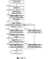
- FIGS. 3C and 3D are graphs of the speed. It is a flowchart of a map display process.
- FIG. 1 is a block diagram showing a configuration of a navigation system 10 as a map display system according to an embodiment of the present invention.
- the navigation system 10 is provided in a vehicle.
- the navigation system 10 includes a control unit 20 and a recording medium 30.
- the control unit 20 includes a CPU, a RAM, a ROM, and the like, and executes a navigation program 21 stored in the recording medium 30 or the ROM.
- the recording medium 30 records map information 30a and route information 30b.
- the map information 30a includes link data specifying a link connecting two nodes, node data indicating the position of the node, and the like.
- a link corresponds to a road section in which the vehicle can travel, and a node corresponds to an intersection that is an end point in the length direction of the link.
- the node data indicates the position of the intersection corresponding to the node.
- the link data includes shape interpolation point data indicating the position of the shape interpolation point set at the center in the link width direction.
- the route information 30b is information indicating a planned travel route connecting the departure point to the destination. Specifically, the route information 30b is information indicating a series of links constituting the planned movement route.
- the vehicle includes a GPS receiver 41, a vehicle speed sensor 42, a gyro sensor 43, and a user I / F unit 44.
- the GPS receiver 41 receives radio waves from GPS satellites and outputs a signal for calculating the current location of the vehicle via an interface (not shown).
- the vehicle speed sensor 42 outputs a signal corresponding to the rotational speed of the wheels provided in the vehicle.
- the control unit 20 acquires the vehicle speed based on a signal from the vehicle speed sensor 42.
- the gyro sensor 43 detects angular acceleration about turning in the horizontal plane of the vehicle, and outputs a signal corresponding to the direction of the vehicle.
- the control unit 20 acquires the traveling direction of the vehicle based on the signal from the gyro sensor 43.
- the control unit 20 acquires the current location of the vehicle by specifying the travel locus of the vehicle based on output signals from the vehicle speed sensor 42 and the gyro sensor 43 and the like.
- the output signal of the GPS receiver 41 is used to correct the current location of the vehicle specified by the vehicle speed sensor 42, the gyro sensor 43, and the like.
- the user I / F unit 44 is an interface unit for providing various types of information to the user or inputting a user instruction.
- the user I / F unit 44 includes a touch panel display (not shown) and a speaker for outputting sound. Yes.
- the touch panel display is a display unit of the present invention and displays a map.
- the control unit 20 outputs a control signal to the user I / F unit 44 to display an arbitrary image, and outputs an arbitrary sound from the speaker.
- the control part 20 acquires a user's setting based on the touch operation with respect to the touchscreen display as an input part.
- the navigation program 21 corresponds to the map display program of the present invention.
- the navigation program 21 includes a destination acquisition module 21a, a position acquisition module 21b, and a display control module 21c.
- the destination acquisition module 21a, the position acquisition module 21b, and the display control module 21c are program modules that cause the control unit 20 as a computer to function as a destination acquisition unit, a position acquisition unit, and a display control unit, respectively.
- the control unit 20 acquires the destination specified on the map displayed on the display unit by the function of the destination acquisition module 21a. Specifically, the control unit 20 displays a map for designating a destination in a map display area provided on the touch panel display by the function of the destination acquisition module 21a.
- FIG. 2A shows an example of a map for designating a destination.
- a map M is displayed in the map display area W.
- the map display area W may be the entire touch panel display or a part thereof.
- the control unit 20 displays a map M, a destination setting button B1, and a cursor C in the map display area W.
- the map M is a map with a scale of 1 / R.
- the reference position P is a position represented by the barycentric position of the map display area W in the map M.
- the control unit 20 receives a touch operation (drag and drop operation, flick operation, pinch-in operation, pinch-out operation, etc.) in the map display area W, and sets the reference position P and the scale 1 / R according to the touch operation.
- a touch operation drag and drop operation, flick operation, pinch-in operation, pinch-out operation, etc.
- the control unit 20 acquires information about the features (links, nodes, facilities, etc.) displayed in the map display area W from the map information 30a according to the reference position P and the scale 1 / R, and adds the acquired information to the acquired information. Based on this, the map M is drawn.
- the control unit 20 receives a touch operation (such as a tap operation, a double tap operation, and a long press operation) on the destination setting button B1, the control unit 20 sets the reference position P when the touch operation is received, to the destination designated by the user. Get as G.
- the control unit 20 has the start position PI that is the position of the map M when the destination G is designated, and the scale 1 / R of the map M when the destination G is designated. Get the starting contract.
- the control unit 20 starts the reference position P of the start map MI, which is the map M when the destination G is designated (when a touch operation on the destination setting button B1 is accepted). Obtained as position PI.
- the control unit 20 acquires the scale 1 / R of the start map MI as the start scale 1 / RI.
- the start position PI and the destination G are the same position. For example, when the position touched by the user is acquired as the destination G, the start position PI and the destination G may be different.
- the reference position P is not necessarily a position represented at the center of gravity of the map display area W.
- the control unit 20 acquires the current location of the vehicle when the destination G is specified as the departure location, and the optimal travel route from the departure location to the destination G is stored in the map information 30a. Search based on. Any method may be used as the search method for the planned movement route, and for example, a known method such as the Dijkstra method can be applied. With the function of the position acquisition module 21b, the control unit 20 records route information 30b indicating a series of links constituting the searched planned travel route on the recording medium 30.
- the control unit 20 allows the end position which is the reference position P of the map M where the entire planned travel route connecting the departure point to the destination G can be displayed, and the entire planned travel route.
- An end scale that is the scale 1 / R of the map M that can be displayed is acquired.
- the control unit 20 acquires the link, the departure point, and the destination G that constitute the planned movement route from the route information 30b, and determines the midpoint of the straight line connecting the departure point and the destination G. Get as end position. That is, the control unit 20 acquires the position of the intermediate point between the departure point and the destination G as the end position.
- the control unit 20 can display the entire planned movement route in the map M.
- Scale 1 / R (scale 1 / R where map M is most detailed) is acquired as the end scale.
- Scales 1 / R that can be set in the present embodiment are 1/2500, 1/5000, 1/10000, 1/2000, 1/4000, 1 / 80,000, 160,000,... Such a discrete value.
- Being able to display the entire planned travel route means that all the links constituting the planned travel route can be displayed.
- FIG. 2B is an example of a map for explaining the end position PE.
- the end position PE is the midpoint of the straight line L connecting the departure point S and the destination G.
- an end map ME which is a map M having the end position PE as the reference position P
- some links of the planned travel route Y are outside the end map ME at a 1/10000 scale 1 / R. If all links of the planned travel route Y are represented in the end map ME at the scale 1 / R of 1/2000, 1/2000 is acquired as the end scale 1 / RE.
- the map M is displayed so that the upper side of the map display area W always indicates north.
- the end position PE does not necessarily have to be the midpoint of the straight line L connecting the departure point S and the destination G.
- the control unit 20 may acquire a rectangular barycentric position similar to the map display area W and circumscribing the planned movement route Y as the end position PE, or the distance from the departure point S on the planned movement route Y.
- a position on the planned movement route Y where the distance from the destination G on the planned movement route Y becomes equal may be acquired as the end position PE.
- the control unit 20 may cause the reference position P to move on the planned movement route Y.
- the control unit 20 controls the display unit by the function of the display control module 21c so that the reference position P of the map M displayed on the display unit gradually moves from the start position PI to the end position PE.
- a period in which the position of the map M gradually moves from the start position PI to the end position PE is defined as a movement period.
- the control unit 20 sets the reference position P at the start time of the movement period as the start position PI, and sets the reference position P at the end time of the movement period as the end position PE. Further, the control unit 20 sets the reference position P at a time other than the start time and the end time in the movement period on the movement line H (start position PI and end position) that is a straight line connecting the start position PI and the end position PE. (Position excluding PE). Specifically, the control unit 20 sets the reference position P at a position closer to the end position PE in the movement line H as the time closer to the end time of the movement period.
- the control unit 20 sets the length of the moving period during which the reference position P of the map M displayed on the display unit gradually moves from the start position PI to the end position PE, from the start position PI to the end position.
- the end distance X which is the distance to the PE, is set to increase as the end distance X increases.
- FIG. 3A is a graph showing the relationship between the end distance X, which is the distance from the start position PI to the end position PE, and the movement period T.
- the control unit 20 acquires the movement period T based on the monotonically increasing function of the end distance X.
- This monotonically increasing function may be a proportional function as shown in FIG. 3A or may be another function (linear or non-linear).
- FIG. 3B is a graph showing the relationship between the end magnification Z that is the magnification of the end scale 1 / RE with respect to the start scale 1 / RI and the movement period T.
- the end magnification Z is a value obtained by dividing the scale denominator RE of the end scale 1 / RE by the scale denominator RI of the start scale 1 / RI, and is RE / RI.
- the end magnification Z is 4 times.
- the end magnification Z is a value obtained by dividing the length of the real space corresponding to a certain distance (for example, 1 cm) on the end map ME by the length of the real space corresponding to the certain distance on the start map MI.
- the control unit 20 acquires the movement period T based on the monotonically increasing function of the end magnification Z.
- the monotonically increasing function may be a proportional function as shown in FIG. 3B or may be another function (linear or non-linear).
- the control unit 20 moves the longer one of the length of the movement period T obtained based on the end distance X and the length of the movement period T obtained based on the end magnification Z. Select as length of period T. Thereby, the possibility that the movement period T that is too short with respect to one of the end distance X or the end magnification Z is set can be reduced.
- the function of the display control module 21c allows the control unit 20 to start the reference portion P of the map M displayed on the display unit in the first part of the movement period T in which the reference position P gradually moves from the start position PI to the end position PE. The speed at which the map M moves is gradually increased. Further, by the function of the display control module 21c, the control unit 20 causes the reference position P of the map M displayed on the display unit to gradually move from the start position PI to the end position PE in the last part of the movement period T. The speed at which the map M moves is gradually reduced.
- FIG. 3C is a graph showing the relationship between the time t within the movement period T and the speed dx / dt at which the reference position P of the map M moves on the movement line H.
- the distance x is a distance from the start position PI on the movement line H to an arbitrary reference position P.
- the control unit 20 divides the movement period T into a start period TI, an intermediate period TK, and an end period TE. Then, the control unit 20 monotonously increases the speed dx / dt in the start period TI that is the first part of the movement period T. Further, the control unit 20 monotonously decreases the speed dx / dt in the end period TE that is the last part of the movement period T. Furthermore, the control unit 20 keeps the speed dx / dt constant in the intermediate period TK.
- the speed dx / dt does not necessarily increase and decrease monotonically linearly, and may increase and decrease monotonically nonlinearly.
- the control unit 20 sets the speed dx / dt in the intermediate period TK to a larger value as the end distance X is larger.
- the function of the display control module 21c causes the control unit 20 to display on the display unit during the movement period T in which the reference position P of the map M displayed on the display unit gradually moves from the start position PI to the end position PE.
- the scale 1 / R of the map M is gradually changed from the start scale 1 / RI to the end scale 1 / RE. That is, the control unit 20 sets the scale denominator R at a time other than the start time and the end time in the movement period T to a value between the scale denominator RI of the start scale 1 / RI and the scale denominator RE of the end scale 1 / RE.
- the control unit 20 sets the scale denominator R to a value closer to the scale denominator RE of the end scale 1 / RE as the time is closer to the end time of the movement period.
- the control unit 20 causes the reference position P of the map M displayed on the display unit to gradually move from the start position PI to the end position PE in the first part of the movement period T. , The rate at which the scale 1 / R of the map M changes gradually increases. Further, by the function of the display control module 21c, the control unit 20 causes the reference position P of the map M displayed on the display unit to gradually move from the start position PI to the end position PE in the last part of the movement period T. The speed at which the scale 1 / R of the map M changes gradually decreases.
- FIG. 3D is a graph showing the relationship between the time t within the movement period T and the speed dz / dt at which the scale 1 / R scale z of the map M changes.
- the magnification z is a value obtained by dividing the scale denominator R of the scale 1 / R of the map M at an arbitrary time t by the scale denominator RI of the start scale 1 / RI, and is R / RI.
- the control unit 20 monotonically increases the speed dz / dt in the start period TI, makes the speed dz / dt constant in the intermediate period TK, and monotonously decreases the speed dz / dt in the end period TE.
- the speed dz / dt does not necessarily increase / decrease linearly and monotonously, and may increase / decrease non-linearly.
- the control unit 20 sets the speed dz / dt in the intermediate period TK to a larger value as the end magnification Z is larger.
- a (discrete value) map M is displayed.
- the start map MI in which the destination G is easy to see at the start time of the movement period T is displayed, and the planned movement route Y is gradually reduced while reducing the scale 1 / R (widening the map M).
- the reference position P of the map M can be gradually moved to the reference position P (end position PE) of the end map ME that can be displayed as a whole. That is, at the time t between the start time of the movement period T when the start map MI indicated by the broken line in FIG. 2B is displayed and the end time of the movement period T when the end map ME indicated by the solid line is displayed, As shown in FIG. 2, a map M is displayed that has a reference position P between the start position PI and the end position PE and a scale 1 / R between the start scale 1 / RI and the end scale 1 / RE.
- the Rukoto is the start map MI in which the destination G is easy to see at the start time of the movement period T is displayed, and the planned movement route Y is gradually reduced while reducing the scale 1 / R (
- the start position PI is the reference position P of the start map MI when the destination G is designated, it can be said that the start position PI is the position of the map M on which the destination G is displayed. . Since the map M gradually moves from the start position PI to the end position PE that is the position of the end map ME where the entire planned travel route Y is displayed, the destination G and the entire planned travel route Y It is possible to easily grasp the positional relationship. That is, in order to gradually move the map M from the state where the destination G is displayed to the state where the entire scheduled route Y including the departure point S is displayed, the planned route Y is traced back from the destination G.
- Such a visual effect makes it easy to grasp the positional relationship between the destination G and the entire planned travel route Y. Since the departure point S that is the starting point of the scheduled movement route Y is also included in the entire planned movement route Y, the positional relationship between the destination G and the departure point S can be easily understood.
- the map can be moved slowly from the start position PI to the end position PE by lengthening the movement period T. Therefore, the change in the position of the map M can be easily recognized, and the positional relationship between the destination G and the planned movement route Y can be easily grasped.
- the movement of the map M can be prevented from suddenly starting, and the position of the map M can be changed. Can be easily recognized. It can be intuitively recognized that the movement of the map M is completed by gradually decreasing the speed dx / dt at which the map M moves in the final end period TE of the movement period T. In addition, it is possible to reduce the possibility that a sense of incongruity may occur due to the sudden movement of the map M.
- the scale 1 / R of the map M displayed on the display unit is gradually changed from the start scale 1 / RI to the end scale 1 / RE, so that the scale 1 / R of the map M is rapidly changed.
- the change can be suppressed, and the transition of the position of the map M can be easily recognized. If the change in the scale 1 / R of the map M is abrupt, there is a high possibility that the change in the position of the map M cannot be easily recognized even if the reference position P of the map M is not suddenly moved. Become.
- the length of the movement period T is set so as to increase as the difference between the start scale 1 / RI and the end scale 1 / RE increases, thereby suppressing an abrupt change in the scale 1 / R of the map M. And the transition of the position of the map M can be easily recognized.
- the transition of the position of the map M can be easily recognized.
- the change in the scale 1 / R of the map M is small in the configuration in which the scale 1 / R of the map M is gradually reduced in the last part of the movement period T. It can be intuitively recognized that the movement of the map M is finished. In addition, it is possible to reduce the possibility that a sense of incongruity may occur due to a sudden change in the scale 1 / R of the map M.
- map display processing Next, the map display process which the control part 20 performs by the function of the navigation program 21 is demonstrated.
- the map display process of this embodiment is a process executed when the destination setting button B1 is operated in a state where the start map MI of FIG. 2A is displayed.
- the control part 20 acquires the destination G by the function of the destination acquisition module 21a (step S100). Specifically, when receiving the touch operation on the destination setting button B1, the control unit 20 acquires the reference position P of the map M when the touch operation is received as the destination G designated by the user. That is, the control unit 20 acquires the reference position P of the start map MI, which is the map M when the destination G is designated, as the destination G.
- the control unit 20 acquires the position of the map M and the scale 1 / R that can display the entire planned travel route Y (step S120). That is, the control unit 20 acquires the end position PE that is the reference position P of the end map ME and the end scale 1 / RE that is the scale 1 / R of the end map ME.
- the end map ME is a map M that can display the entire planned travel route Y.
- the end position PE is the position of the midpoint of the straight line L connecting the starting point S and the destination G.
- the end scale 1 / RE is the maximum scale 1 / RE at which the entire travel route Y can be displayed in the map M when the map M having the end position PE as the reference position P is displayed.
- R (a discrete value at a scale of 1 / R at which the map M is most detailed).
- the control unit 20 determines whether or not the scale of the map M that can display the entire planned travel route Y is larger than the current map M (step S130). That is, the control unit 20 determines whether or not the end scale 1 / RE that is the scale 1 / R of the end map ME is larger than the start scale 1 / RI that is the scale 1 / R of the start map MI. That is, the control unit 20 determines whether or not the map M is widened (zoomed out) when the state is changed from the state in which the start map MI is displayed to the state in which the end map ME is displayed.
- the control unit 20 searches for a planned movement route Y that connects the departure point S (current location of the vehicle) to the destination G. .
- the control unit 20 uses the function of the display control module 21c to move.
- a map M capable of displaying the entire planned route Y is drawn (step S140). That is, the control unit 20 draws the end map ME.
- the control unit 20 displays a map M that can display the entire travel route Y (step S150). That is, the control unit 20 displays the end map ME on a touch panel display as a display unit, thereby switching from a state in which the start map MI is displayed to a state in which the end map ME is displayed (the reference position P is gradually moved). Without).
- the start is a case where the map M is refined (zoomed in) when switching from the state of displaying the map MI to the state of displaying the end map ME. That is, there is a high possibility that the entire travel route Y can be displayed on the start map MI, and even if the destination map G is suddenly switched from the state where the start map MI is displayed to the state where the end map ME is displayed. It can be considered that it is easy to grasp the positional relationship with the planned movement route Y. Therefore, the process of gradually moving the reference position P of the map M in the movement period T can be omitted.
- step S130: Y when it is determined that the scale 1 / R of the map M that can display the entire planned travel route Y is larger than the current map M (step S130: Y), the control unit 20 moves by the function of the display control module 21c. A map M that can display the entire planned route Y is drawn (step S160). That is, the control unit 20 draws the end map ME as in step S140.
- the control unit 20 sets the position of the map M and the scale 1 / R in the movement period T by the function of the display control module 21c (step S180).
- the control unit 20 sets the movement period T longer as the end distance X and the end magnification Z are larger.
- the control unit 20 sets the reference position P and the scale 1 / R of the map M at each time t in the movement period T.
- the control unit 20 divides the movement period T into a start period TI, an intermediate period TK, and an end period TE. In the start period TI, the reference position P and the scale 1 are divided.
- the control unit 20 gradually changes the position of the map M and the scale 1 / R by the function of the display control module 21c (step S190). That is, the control unit 20 sets the reference position P and the scale 1 / R of the map M at each time t based on the speeds dx / dt and dz / dt at each time t set in step S180. Thereby, the control unit 20 gradually moves the reference position P of the map M from the start position PI toward the end position PE in the movement period T, and the scale 1 / R of the map M ends from the start scale 1 / RI.
- the touch panel display as the display unit is controlled so as to gradually change to the scale 1 / RE.
- the control unit 20 draws in advance an end map ME that can display the entire planned travel route Y (step S160), and cuts out a part of the end map ME to map the map M at each time t. Is generated. That is, the control unit 20 sets the position and size of the region to be cut out from the end map ME based on the reference position P and the magnification z set for each time t, whereby the map M at each time t (in FIG. 2B). A map M in a one-dot chain line) is generated, and display data of the map M is output to a touch panel display.
- the control unit 20 may draw a map M corresponding to the magnification z and the reference position P at each time t at each time t.
- step S190 the end map ME is finally displayed as in step S150.
- the control unit 20 displays a guidance start button B2 on the touch panel display together with the end map ME, and performs guidance of the planned movement route Y when the guidance start button B2 is operated.
- the length of the movement period T is set based on the end distance X, which is the distance from the start position PI to the end position PE.
- the length of the movement period T is independent of the end distance X. There may be.
- the length of the movement period T may be independent of the end magnification Z.
- the length of the movement period T may depend only on the end distance X, or may depend only on the end magnification Z.
- the length of the movement period T may be set to a predetermined fixed length, or may be set to a length set by the user.
- the length of the movement period T may be set longer as the route length of the planned movement route Y is longer.
- the movement period T is not necessarily divided into the start period TI, the intermediate period TK, and the end period TE, and either the start period TI or the end period TE does not have to be provided. That is, in the movement period T, the speed dx / dt, dz / dt at which the magnification z of the reference position P and the scale 1 / R changes monotonically increases, and the speeds dx / dt, dz / dt are constant. It may be configured only by the intermediate period TK.
- the speed dx / dt, dz / dt monotonously decreases during the intermediate period TK in which the speeds dx / dt, dz / dt at which the magnification z of the reference position P and the scale 1 / R changes are constant. It may be configured only by the end period TE. Further, in the movement period T, the speed dx / dt, dz / dt at which the magnification z of the reference position P and the scale 1 / R changes monotonically increases, and the speeds dx / dt, dz / dt monotonously decrease. It may be configured only by the end period TE.
- the speeds dx / dt and dz / dt at which the magnification z of the reference position P and the scale 1 / R changes may monotonously increase, may be constant, or monotonic. May decrease.
- the speeds dx / dt and dz / dt at which the magnification z of the reference position P and the scale 1 / R changes in the entire period of the movement period T may be defined by a non-linear function that is convex upward.
- the start period TI, the intermediate period TK, and the end period TE may not be common to the reference position P, the changing speed dx / dt, and the changing speed dz / dt of the scale 1 / R. .
- the speed dx / dt is set according to the start period TI, the intermediate period TK, and the end period TE, while the speed z of the scale 1 / R changes.
- the speed dz / dt may be set so as to be constant throughout the movement period T.
- the reference position P of the map M is gradually moved during the movement period T. You may let them. Even in such a case, it is possible to prevent the map M from switching suddenly, and to reduce the user's uncomfortable feeling.
- the present invention only needs to be configured so as to gradually move the reference position P of the map M at least during the movement period T. Therefore, the control unit 20 gradually moves the reference position P of the map M while maintaining the start scale 1 / RI of the start map MI, and sets the scale 1 / R of the map M when the reference position P moves to the end position PE.
- the start scale 1 / RI may be switched to the end scale 1 / RE. Further, the control unit 20 may first switch the scale 1 / R of the map M from the start scale 1 / RI to the end scale 1 / RE, and then gradually move the reference position P of the map M to the end position PE. Good.
- the map display system may be a vehicle-mounted device provided in a vehicle or a device that is not mounted on a vehicle.
- the display unit may be included in the map display system, or may be provided in a device that can communicate with the map display system.
- the destination acquisition unit may acquire a destination designated on the map, and may acquire a position corresponding to the position operated by the user on the map as the destination.
- the position operated by the user may be a position where the user touches a finger or the like on the touch panel display on which the map is displayed.
- the position operated by the user may be the position of the cursor on the map, or the user's operation for relative movement between the cursor and the map (movement of the cursor or scrolling of the map) may be accepted.
- the start position is the position of the map where the destination is displayed on the map.
- the map position such as the start position or the end position may be, for example, a position represented by a specific position on the display unit among positions on the map.
- the specific position may be the center position of the map display area where the map is displayed on the display unit, or may be any one of the four corners.
- the destination is the final destination of the planned travel route, and a transit point in the middle of the planned travel route may be set in addition to the destination.
- the departure place may be, for example, the current position of the vehicle or the user, or may be a position set by the user.
- the planned travel route is a route connecting the departure point to the destination, and may be a route searched after at least the destination is set.
- the display of the entire planned travel route may be that all parts constituting the planned travel route may be displayed, or the starting point and the destination may be displayed.
- the planned movement route may be single or plural. When there are a plurality of planned travel routes, the position of the map on which all the plurality of planned travel routes are displayed is the end position.
- the display control unit may control the display unit so that the map position gradually moves from the start position to the end position, and the map position moves stepwise on a moving line connecting the start position and the end position.
- the movement line may be a straight line connecting the start position and the end position, may be a curve connecting the start position and the end position, and is formed along the planned movement path or the planned movement path. It may be a line.
- To move in stages means that the position of the map moves via at least one relay position that exists between the start position and the end position on the movement line. The map position can be moved more smoothly as the number of relay positions through which the map position passes is increased.
- the display control unit sets the length of the moving period in which the position of the map displayed on the display unit gradually moves from the start position to the end position so that the distance from the start position to the end position increases. May be. In this way, when the distance from the start position to the end position increases, the map can be moved slowly from the start position to the end position by increasing the length of the movement period. Therefore, it is possible to easily recognize the change of the map position, and to easily grasp the positional relationship between the destination and the planned movement route.
- the length of the movement period only needs to monotonously increase according to the distance from the start position to the end position, and may be linearly long or non-linearly long.
- the display control unit may gradually increase the moving speed of the map in the first part of the moving period in which the position of the map displayed on the display unit gradually moves from the start position to the end position. . Thereby, it can suppress that the movement of a map starts suddenly, and can recognize the transition of the position of a map easily.
- the display control unit may gradually reduce the speed at which the map moves in the last part of the movement period in which the position of the map displayed on the display unit gradually moves from the start position to the end position. .
- the display control unit may gradually reduce the speed at which the map moves in the last part of the movement period in which the position of the map displayed on the display unit gradually moves from the start position to the end position.
- the display control unit obtains a start scale which is a scale of the map when the destination is specified, and an end scale which is a scale of the map that can display the entire planned travel route, and displays it on the display unit.
- the scale of the map displayed on the display unit is gradually changed from the start scale to the end scale.
- the display control unit sets the length of the moving period in which the position of the map displayed on the display unit gradually moves from the start position to the end position so that the longer the difference between the start scale and the end scale, the longer May be.
- the display control unit gradually increases the speed at which the map scale changes in the first part of the movement period in which the position of the map displayed on the display unit gradually moves from the start position to the end position. Also good. Thereby, a rapid change in the scale of the map can be suppressed, and a change in the map position can be easily recognized.
- the display control unit gradually decreases the speed at which the map scale changes in the last part of the movement period in which the position of the map displayed on the display unit gradually moves from the start position to the end position. May be.
- the display control unit gradually decreases the speed at which the map scale changes in the last part of the movement period in which the position of the map displayed on the display unit gradually moves from the start position to the end position. May be.
- the method of gradually moving the map from the start position can be applied as a program or method.
- the system, program, and method as described above may be realized as a single device, or may be realized using components shared with each part of the vehicle, and include various aspects. It is a waste.
- some changes may be made as appropriate, such as a part of software and a part of hardware.
- the invention is also established as a recording medium for a program for controlling the apparatus.
- the software recording medium may be a magnetic recording medium, a magneto-optical recording medium, or any recording medium to be developed in the future.
Landscapes
- Engineering & Computer Science (AREA)
- Radar, Positioning & Navigation (AREA)
- Remote Sensing (AREA)
- Physics & Mathematics (AREA)
- Theoretical Computer Science (AREA)
- General Physics & Mathematics (AREA)
- Automation & Control Theory (AREA)
- General Engineering & Computer Science (AREA)
- Mathematical Physics (AREA)
- Business, Economics & Management (AREA)
- Educational Administration (AREA)
- Educational Technology (AREA)
- Human Computer Interaction (AREA)
- Navigation (AREA)
- Instructional Devices (AREA)
- User Interface Of Digital Computer (AREA)
Abstract
【課題】目的地と経路との位置関係を把握しやすくする技術の提供。 【解決手段】地図表示システムは、表示部に表示された地図上にて指定された目的地を取得する目的地取得部と、目的地が指定された際の地図の位置である開始位置と、出発地から目的地までを接続する移動予定経路の全体が表示可能となる地図の位置である終了位置とを取得する位置取得部と、表示部に表示される地図の位置が開始位置から終了位置まで徐々に移動するように表示部を制御するとともに、目的地が指定された際の地図の縮尺である開始縮尺と、移動予定経路の全体が表示可能となる地図の縮尺である終了縮尺とを取得し、表示部に表示される地図の位置が開始位置から終了位置まで徐々に移動する移動期間において、表示部に表示される地図の縮尺を開始縮尺から終了縮尺まで徐々に変化させる表示制御部と、を備える。
Description
本発明は、地図表示システムおよび地図表示プログラムに関する。
目的地を設定した後に、当該目的地までのルートの全体を表示する技術が知られている(特許文献1の図9,図14参照)。
特許文献1において、目的地が表示されている地図から、ルートの全体が表示可能な地図へと急激に遷移すると、目的地とルートとの位置関係が把握しづらくなるという問題があった。
本発明は、前記課題にかんがみてなされたもので、目的地と経路との位置関係を把握しやすくする技術を提供することを目的とする。
本発明は、前記課題にかんがみてなされたもので、目的地と経路との位置関係を把握しやすくする技術を提供することを目的とする。
前記の目的を達成するため、本発明の地図表示システムは、表示部に表示された地図上にて指定された目的地を取得する目的地取得部と、目的地が指定された際の地図の位置である開始位置と、出発地から目的地までを接続する移動予定経路の全体が表示可能となる地図の位置である終了位置とを取得する位置取得部と、表示部に表示される地図の位置が開始位置から終了位置まで徐々に移動するように表示部を制御する表示制御部と、を備える。さらに、表示制御部は、目的地が指定された際の地図の縮尺である開始縮尺と、移動予定経路の全体が表示可能となる地図の縮尺である終了縮尺とを取得し、表示部に表示される地図の位置が開始位置から終了位置まで徐々に移動する移動期間において、表示部に表示される地図の縮尺を開始縮尺から終了縮尺まで徐々に変化させる。
前記の目的を達成するため、本発明の地図表示プログラムは、コンピュータを、表示部に表示された地図上にて指定された目的地を取得する目的地取得部、目的地が指定された際の地図の位置である開始位置と、出発地から目的地までを接続する移動予定経路の全体が表示可能となる地図の位置である終了位置とを取得する位置取得部、表示部に表示される地図の位置が開始位置から終了位置まで徐々に移動するように表示部を制御する表示制御部、として機能させる。さらに、表示制御部は、目的地が指定された際の地図の縮尺である開始縮尺と、移動予定経路の全体が表示可能となる地図の縮尺である終了縮尺とを取得し、表示部に表示される地図の位置が開始位置から終了位置まで徐々に移動する移動期間において、表示部に表示される地図の縮尺を開始縮尺から終了縮尺まで徐々に変化させる。
前記の構成において、開始位置は、目的地が指定された際の地図の位置であるため、目的地が表示される地図の位置であると言える。このような開始位置から、移動予定経路の全体が表示される地図の位置である終了位置まで地図が徐々に移動するため、目的地と移動予定経路の全体との位置関係を把握しやすくすることができる。すなわち、目的地が表示される状態から出発地を含む移動予定経路の全体が表示される状態へと地図を徐々に移動させるため、目的地から移動予定経路を遡っていくような視覚的効果によって目的地と移動予定経路の全体との位置関係を把握しやすくすることができる。また、移動予定経路には当該移動予定経路の始点である出発地も含まれるため、目的地と出発地との位置関係を把握しやすくすることができる。さらに、表示部に表示される地図の縮尺を開始縮尺から終了縮尺まで徐々に変化させることにより、急激な地図の縮尺の変化を抑制することができ、地図の位置の移り変わりを容易に認識することができる。
ここでは、下記の順序に従って本発明の実施の形態について説明する。
(1)ナビゲーションシステムの構成:
(2)地図表示処理:
(3)他の実施形態:
(1)ナビゲーションシステムの構成:
(2)地図表示処理:
(3)他の実施形態:
(1)ナビゲーションシステムの構成:
図1は、本発明の一実施形態にかかる地図表示システムとしてのナビゲーションシステム10の構成を示すブロック図である。ナビゲーションシステム10は、車両に備えられている。ナビゲーションシステム10は、制御部20と記録媒体30とを備えている。制御部20は、CPUとRAMとROM等を備え、記録媒体30やROMに記憶されたナビゲーションプログラム21を実行する。
図1は、本発明の一実施形態にかかる地図表示システムとしてのナビゲーションシステム10の構成を示すブロック図である。ナビゲーションシステム10は、車両に備えられている。ナビゲーションシステム10は、制御部20と記録媒体30とを備えている。制御部20は、CPUとRAMとROM等を備え、記録媒体30やROMに記憶されたナビゲーションプログラム21を実行する。
記録媒体30は、地図情報30aと経路情報30bとを記録している。地図情報30aは、2個のノード間を接続するリンクを特定するリンクデータと、ノードの位置等を示すノードデータ等を含む。リンクは車両が走行可能な道路区間に対応し、ノードはリンクの長さ方向の端点である交差点に対応する。ノードデータは、ノードに対応する交差点の位置を示す。リンクデータには、リンクの幅方向の中央に設定された形状補間点の位置を示す形状補間点データが含まれている。経路情報30bは、出発地から目的地までを接続する移動予定経路を示す情報である。具体的に、経路情報30bは、移動予定経路を構成する一連のリンクを示す情報である。
車両は、GPS受信部41と車速センサ42とジャイロセンサ43とユーザI/F部44とを備えている。GPS受信部41は、GPS衛星からの電波を受信し、図示しないインタフェースを介して車両の現在地を算出するための信号を出力する。車速センサ42は、車両が備える車輪の回転速度に対応した信号を出力する。制御部20は、車速センサ42からの信号に基づいて車速を取得する。ジャイロセンサ43は、車両の水平面内の旋回についての角加速度を検出し、車両の向きに対応した信号を出力する。制御部20は、ジャイロセンサ43からの信号に基づいて車両の進行方向を取得する。制御部20は、車速センサ42およびジャイロセンサ43等の出力信号に基づいて車両の走行軌跡を特定することで車両の現在地を取得する。GPS受信部41の出力信号は、車速センサ42およびジャイロセンサ43等から特定される車両の現在地を補正する等に利用される。
ユーザI/F部44は、ユーザに各種の情報を提供し、またはユーザの指示を入力するためのインタフェース部であり、本実施形態においては図示しないタッチパネルディスプレイと音声を出力するスピーカーとを備えている。タッチパネルディスプレイは、本発明の表示部であり、地図を表示する。制御部20は、当該ユーザI/F部44に対して制御信号を出力して任意の画像を表示し、任意の音声をスピーカーから出力する。また、制御部20は、入力部としてのタッチパネルディスプレイに対するタッチ操作に基づいて利用者の設定を取得する。
ナビゲーションプログラム21は、本発明の地図表示プログラムに相当する。ナビゲーションプログラム21は、目的地取得モジュール21aと位置取得モジュール21bと表示制御モジュール21cとを含む。目的地取得モジュール21aと位置取得モジュール21bと表示制御モジュール21cとは、それぞれコンピュータとしての制御部20を目的地取得部と位置取得部と表示制御部として機能させるプログラムモジュールである。
目的地取得モジュール21aの機能により制御部20は、表示部に表示された地図上にて指定された目的地を取得する。具体的に、目的地取得モジュール21aの機能により制御部20は、タッチパネルディスプレイに設けられている地図表示領域に、目的地を指定するための地図を表示する。
図2Aは、目的地を指定するための地図の例を示す。図2Aに示すように、地図表示領域Wに地図Mが表示されている。地図表示領域Wは、タッチパネルディスプレイの全体であってもよいし、一部分であってもよい。制御部20は、地図表示領域Wにおいて、地図Mと目的地設定ボタンB1とカーソルCとを表示する。地図Mは、縮尺1/Rの地図である。ここで、基準位置Pは、地図Mのうち地図表示領域Wの重心位置に表される位置である。制御部20は、地図表示領域Wにおけるタッチ操作(ドラッグアンドドロップ操作,フリック操作,ピンチイン操作,ピンチアウト操作等)を受け付け、当該タッチ操作に応じて基準位置Pと縮尺1/Rを設定する。制御部20は、基準位置Pと縮尺1/Rに応じて地図表示領域Wに表示される地物(リンク,ノード,施設等)についての情報を地図情報30aから取得し、当該取得した情報に基づいて地図Mを描画する。制御部20は、目的地設定ボタンB1に対するタッチ操作(タップ操作,ダブルタップ操作,長押し操作等)を受け付けると、タッチ操作が受け付けられた際の基準位置Pを、利用者が指定した目的地Gとして取得する。
位置取得モジュール21bの機能により制御部20は、目的地Gが指定された際の地図Mの位置である開始位置PIと、目的地Gが指定された際の地図Mの縮尺1/Rである開始縮とを取得する。位置取得モジュール21bの機能により制御部20は、目的地Gが指定された際(目的地設定ボタンB1に対するタッチ操作が受け付けられた際)の地図Mである開始地図MIの基準位置Pを、開始位置PIとして取得する。さらに、制御部20は、開始地図MIの縮尺1/Rを、開始縮尺1/RIとして取得する。本実施形態において、開始位置PIと目的地Gとは同じ位置である。利用者がタッチ操作した位置を目的地Gとして取得する場合等においては、開始位置PIと目的地Gとが異なり得る。また、基準位置Pは必ずしも地図表示領域Wの重心に表された位置でなくてもよい。
位置取得モジュール21bの機能により制御部20は、目的地Gが指定された際の車両の現在地を出発地として取得し、当該出発地から目的地Gまでの最適な移動予定経路を地図情報30aに基づいて探索する。移動予定経路の探索手法は、どのような手法であってもよく、例えばダイクストラ法等の公知の手法を適用できる。位置取得モジュール21bの機能により制御部20は、探索した移動予定経路を構成する一連のリンクを示す経路情報30bを記録媒体30に記録する。
位置取得モジュール21bの機能により制御部20は、出発地から目的地Gまでを接続する移動予定経路の全体が表示可能となる地図Mの基準位置Pである終了位置と、移動予定経路の全体が表示可能となる地図Mの縮尺1/Rである終了縮尺とを取得する。位置取得モジュール21bの機能により制御部20は、経路情報30bから移動予定経路を構成するリンクと出発地と目的地Gとを取得し、出発地と目的地Gとを接続する直線の中点を終了位置として取得する。すなわち、制御部20は、出発地と目的地Gの中間地点の位置を終了位置として取得する。さらに、制御部20は、設定可能な縮尺1/Rのうち、終了位置を基準位置Pとする地図Mを表示した場合に、当該地図M内に移動予定経路の全体が表示可能となる最大の縮尺1/R(最も地図Mが詳細となる縮尺1/R)を終了縮尺として取得する。本実施形態において設定可能な縮尺1/Rは、1/2500,1/5000,1/1万,1/2万,1/4万,1/8万,1/16万・・・・のような離散値である。移動予定経路の全体が表示可能となるとは、移動予定経路を構成するすべてのリンクが表示可能となることを意味する。
図2Bは、終了位置PEを説明する地図の例である。図2Bに示すように、終了位置PEは、出発地Sと目的地Gとを接続する直線Lの中点となっている。例えば、終了位置PEを基準位置Pとする地図Mである終了地図MEを描画した場合に、1/1万の縮尺1/Rでは移動予定経路Yの一部のリンクが終了地図MEの外部に位置し、1/2万の縮尺1/Rでは移動予定経路Yのすべてのリンクが終了地図ME内に表される場合には、1/2万が終了縮尺1/REとして取得される。なお、本実施形態において、地図表示領域Wの上方が常に北を示すように地図Mが表示されることとする。ここで、必ずしも終了位置PEは出発地Sと目的地Gとを接続する直線Lの中点でなくてもよい。例えば、制御部20は、地図表示領域Wと相似かつ移動予定経路Yに外接する矩形の重心位置を終了位置PEとして取得してもよいし、移動予定経路Y上における出発地Sからの距離と移動予定経路Y上における目的地Gからの距離が等しくなる移動予定経路Y上の位置を終了位置PEとして取得してもよい。この場合、制御部20は、移動予定経路Y上を基準位置Pが移動するようにしてもよい。
表示制御モジュール21cの機能により制御部20は、表示部に表示される地図Mの基準位置Pが開始位置PIから終了位置PEまで徐々に移動するように表示部を制御する。ここで、地図Mの位置が開始位置PIから終了位置PEまで徐々に移動する期間を移動期間と定義する。制御部20は、移動期間の開始時刻における基準位置Pを開始位置PIと設定し、移動期間の終了時刻における基準位置Pを終了位置PEと設定する。さらに、制御部20は、移動期間のうち開始時刻と終了時刻以外の時刻における基準位置Pを、開始位置PIと終了位置PEとを接続する直線である移動線H上(開始位置PIと終了位置PEを除く位置)に設定する。具体的に、制御部20は、移動期間の終了時刻に近い時刻ほど、移動線Hのうち終了位置PEに近い位置に基準位置Pを設定する。
表示制御モジュール21cの機能により制御部20は、表示部に表示される地図Mの基準位置Pが開始位置PIから終了位置PEまで徐々に移動する移動期間の長さを、開始位置PIから終了位置PEまでの距離である終了距離Xが大きいほど長くなるように設定する。図3Aは、開始位置PIから終了位置PEまでの距離である終了距離Xと移動期間Tとの関係を示すグラフである。制御部20は、終了距離Xの単調増加関数に基づいて移動期間Tを取得する。この単調増加関数は、図3Aのように比例関数であってもよいし、他の関数(線形・非線形)であってもよい。
また、表示制御モジュール21cの機能により制御部20は、表示部に表示される地図Mの基準位置Pが開始位置PIから終了位置PEまで徐々に移動する移動期間Tの長さを、開始縮尺1/RIと終了縮尺1/REとの差が大きいほど長くなるように設定する。図3Bは、開始縮尺1/RIに対する終了縮尺1/REの倍率である終了倍率Zと移動期間Tとの関係を示すグラフである。終了倍率Zは、終了縮尺1/REの縮尺分母REを開始縮尺1/RIの縮尺分母RIで除算した値であり、RE/RIである。例えば、終了縮尺1/REが1/1万であり開始縮尺1/RIが1/2500である場合、終了倍率Zは4倍となる。終了倍率Zは、終了地図ME上における一定距離(例えば1cm)に対応する実空間の長さを、開始地図MI上における当該一定距離に対応する実空間の長さで除算した値である。制御部20は、終了倍率Zの単調増加関数に基づいて移動期間Tを取得する。この単調増加関数は、図3Bのように比例関数であってもよいし、他の関数(線形・非線形)であってもよい。
表示制御モジュール21cの機能により制御部20は、終了距離Xに基づいて得られた移動期間Tの長さと、終了倍率Zに基づいて得られた移動期間Tの長さのうち、長い方を移動期間Tの長さとして選択する。これにより、終了距離Xまたは終了倍率Zの一方に対して短すぎる移動期間Tが設定される可能性を低減できる。
さらに、表示制御モジュール21cの機能により制御部20は、表示部に表示される地図Mの基準位置Pが開始位置PIから終了位置PEまで徐々に移動する移動期間Tのうちの最初の部分において、地図Mが移動する速度を徐々に大きくする。また、表示制御モジュール21cの機能により制御部20は、表示部に表示される地図Mの基準位置Pが開始位置PIから終了位置PEまで徐々に移動する移動期間Tのうちの最後の部分において、地図Mが移動する速度を徐々に小さくする。
図3Cは、移動期間T内の時刻tと、地図Mの基準位置Pが移動線H上を移動する速度dx/dtとの関係を示すグラフである。なお、距離xは、移動線H上における開始位置PIから任意の基準位置Pまでの距離である。制御部20は、移動期間Tを開始期間TIと中間期間TKと終了期間TEに3分割する。そして、制御部20は、移動期間Tのうちの最初の部分である開始期間TIにおいて速度dx/dtを単調増加させる。また、制御部20は、移動期間Tのうちの最後の部分である終了期間TEにおいて速度dx/dtを単調減少させる。さらに、制御部20は、中間期間TKにおいて速度dx/dtを一定とする。速度dx/dtは、必ずしも線形的に単調増加・減少しなくてもよく、非線形的に単調増加・減少してもよい。
制御部20は、終了距離Xが大きいほど、中間期間TKにおける速度dx/dtを大きい値に設定する。制御部20は、終了距離Xや終了倍率Zが大きいほど、中間期間TKが長くなるように、開始期間TIと中間期間TKと終了期間TEとを設定してもよい。なお、制御部20は、移動期間Tの開始時刻(t=0)から任意の時刻tまで速度dx/dtを定積分することにより、任意の時刻tにおける距離x(基準位置P)を取得する。
さらに、表示制御モジュール21cの機能により制御部20は、表示部に表示される地図Mの基準位置Pが開始位置PIから終了位置PEまで徐々に移動する移動期間Tにおいて、表示部に表示される地図Mの縮尺1/Rを開始縮尺1/RIから終了縮尺1/REまで徐々に変化させる。すなわち、制御部20は、移動期間Tのうち開始時刻と終了時刻以外の時刻における縮尺分母Rを、開始縮尺1/RIの縮尺分母RIと終了縮尺1/REの縮尺分母REとの間の値に設定する。具体的に、制御部20は、移動期間の終了時刻に近い時刻ほど、終了縮尺1/REの縮尺分母REに近い値に縮尺分母Rを設定する。
具体的に、表示制御モジュール21cの機能により制御部20は、表示部に表示される地図Mの基準位置Pが開始位置PIから終了位置PEまで徐々に移動する移動期間Tのうちの最初の部分において、地図Mの縮尺1/Rが変化する速度を徐々に大きくする。また、表示制御モジュール21cの機能により制御部20は、表示部に表示される地図Mの基準位置Pが開始位置PIから終了位置PEまで徐々に移動する移動期間Tのうちの最後の部分において、地図Mの縮尺1/Rが変化する速度を徐々に小さくする。
図3Dは、移動期間T内の時刻tと、地図Mの縮尺1/Rの倍率zが変化する速度dz/dtとの関係を示すグラフである。倍率zとは、任意の時刻tにおける地図Mの縮尺1/Rの縮尺分母Rを開始縮尺1/RIの縮尺分母RIで除算した値であり、R/RIである。制御部20は、開始期間TIにおいては速度dz/dtを単調増加させ、中間期間TKにおいては速度dz/dtを一定とし、終了期間TEにおいては速度dz/dtを単調減少させる。速度dz/dtは、必ずしも線形的に単調増加・減少しなくてもよく、非線形的に単調増加・減少してもよい。
制御部20は、終了倍率Zが大きいほど、中間期間TKにおける速度dz/dtを大きい値に設定する。なお、制御部20は、移動期間Tの開始時刻(t=0)から任意の時刻tまで速度dz/dtを定積分することにより、任意の時刻tにおける倍率zを取得する。また、制御部20は、任意の時刻tにおける倍率zに基づいて、任意の時刻tにおける縮尺1/R(R=z×RI)を取得し、当該縮尺1/Rに最も近い縮尺1/R(離散値)の地図Mを表示する。
以上のようにすることにより、移動期間Tの開始時刻において目的地Gが見やすい開始地図MIを表示させ、徐々に縮尺1/Rを小さくしながら(地図Mを広域化しながら)、移動予定経路Yの全体が表示可能な終了地図MEの基準位置P(終了位置PE)まで徐々に地図Mの基準位置Pを移動させていくことができる。すなわち、図2Bにて破線で示す開始地図MIが表示される移動期間Tの開始時刻と、実線で示す終了地図MEが表示される移動期間Tの終了時刻との間の時刻tにおいて、一点鎖線で示すように開始位置PIと終了位置PEとの間の位置が基準位置Pとなり、かつ、開始縮尺1/RIと終了縮尺1/REとの間の縮尺1/Rとなる地図Mが表示されることとなる。
以上説明した本実施形態の構成において、開始位置PIは、目的地Gが指定された際の開始地図MIの基準位置Pであるため、目的地Gが表示される地図Mの位置であると言える。このような開始位置PIから、移動予定経路Yの全体が表示される終了地図MEの位置である終了位置PEまで地図Mが徐々に移動するため、目的地Gと移動予定経路Yの全体との位置関係を把握しやすくすることができる。すなわち、目的地Gが表示される状態から出発地Sを含む移動予定経路Yの全体が表示される状態へと地図Mを徐々に移動させるため、目的地Gから移動予定経路Yを遡っていくるような視覚的効果によって目的地Gと移動予定経路Yの全体との位置関係を把握しやすくすることができる。移動予定経路Yの全体には当該移動予定経路Yの始点である出発地Sも含まれるため、目的地Gと出発地Sとの位置関係を把握しやすくすることができる。
また、開始位置PIから終了位置PEまで移動する終了距離Xが大きくなる場合に移動期間Tを長くすることにより、開始位置PIから終了位置PEまでゆっくりと地図を移動させることができる。従って、地図Mの位置の移り変わりを容易に認識することができ、目的地Gと移動予定経路Yとの位置関係を把握しやすくすることができる。
移動期間Tのうちの最初の開始期間TIにおいて、地図Mが移動する速度dx/dtを徐々に大きくすることにより、急激に地図Mの移動が開始することを抑制でき、地図Mの位置の移り変わりを容易に認識することができる。移動期間Tのうちの最後の終了期間TEにおいて、地図Mが移動する速度dx/dtを徐々に小さくすることにより、地図Mの移動が終了することを直感的に認識できる。また、急激に地図Mの移動が停止することによって違和感が生じる可能性を低減できる。
また、移動期間Tにおいて、表示部に表示される地図Mの縮尺1/Rを開始縮尺1/RIから終了縮尺1/REまで徐々に変化させることにより、急激な地図Mの縮尺1/Rの変化を抑制することができ、地図Mの位置の移り変わりを容易に認識することができる。なお、地図Mの縮尺1/Rの変化が急である場合には、地図Mの基準位置Pの移動が急でなくても、地図Mの位置の移り変わりを容易に認識できなくなる可能性が大きくなる。
また、移動期間Tの長さを、開始縮尺1/RIと終了縮尺1/REとの差が大きいほど長くなるように設定することにより、急激な地図Mの縮尺1/Rの変化を抑制することができ、地図Mの位置の移り変わりを容易に認識することができる。
移動期間Tのうちの最初の開始期間TIにおいて、地図Mの縮尺1/Rが変化する速度を徐々に大きくすることにより、急激な地図Mの縮尺1/Rの変化を抑制することができ、地図Mの位置の移り変わりを容易に認識することができる。移動期間Tのうちの最後の部分において、地図Mの縮尺1/Rが変化する速度を徐々に小さくする構成において、地図Mの縮尺1/Rの変化が小さくなっていることを認識することにより、地図Mの移動が終了することを直感的に認識できる。また、急激に地図Mの縮尺1/Rの変化が停止することによって違和感が生じる可能性を低減できる。
(2)地図表示処理:
次に、ナビゲーションプログラム21の機能により制御部20が実行する地図表示処理を説明する。本実施形態の地図表示処理は、図2Aの開始地図MIを表示している状態において目的地設定ボタンB1が操作された場合に実行される処理である。
次に、ナビゲーションプログラム21の機能により制御部20が実行する地図表示処理を説明する。本実施形態の地図表示処理は、図2Aの開始地図MIを表示している状態において目的地設定ボタンB1が操作された場合に実行される処理である。
まず、目的地取得モジュール21aの機能により制御部20は、目的地Gを取得する(ステップS100)。具体的に、制御部20は、目的地設定ボタンB1に対するタッチ操作を受け付けると、タッチ操作が受け付けられた際の地図Mの基準位置Pを、利用者が指定した目的地Gとして取得する。すなわち、制御部20は、目的地Gが指定された際の地図Mである開始地図MIの基準位置Pを目的地Gとして取得する。
次に、位置取得モジュール21bの機能により制御部20は、現在の地図Mの位置と縮尺1/Rとを取得する(ステップS110)。すなわち、制御部20は、開始地図MIの基準位置Pである開始位置PI(=目的地G)と、開始地図MIの縮尺1/Rである開始縮尺1/RIとを取得する。
次に、位置取得モジュール21bの機能により制御部20は、移動予定経路Yの全体を表示可能な地図Mの位置と縮尺1/Rとを取得する(ステップS120)。すなわち、制御部20は、終了地図MEの基準位置Pである終了位置PEと、終了地図MEの縮尺1/Rである終了縮尺1/REとを取得する。終了地図MEは、移動予定経路Yの全体を表示可能な地図Mである。本実施形態において、終了位置PEは、出発地Sと目的地Gとを接続する直線Lの中点の位置である。本実施形態において、終了縮尺1/REは、終了位置PEを基準位置Pとする地図Mを表示した場合に、当該地図M内に移動予定経路Yの全体が表示可能となる最大の縮尺1/R(最も地図Mが詳細となる縮尺1/Rの離散値)である。
次に、表示制御モジュール21cの機能により制御部20は、移動予定経路Yの全体を表示可能な地図Mの縮尺が現在の地図Mより大きいか否かを判定する(ステップS130)。すなわち、制御部20は、終了地図MEの縮尺1/Rである終了縮尺1/REが、開始地図MIの縮尺1/Rである開始縮尺1/RIよりも大きいか否かを判定する。つまり、制御部20は、開始地図MIを表示する状態から終了地図MEを表示する状態へと切り替えた場合に、地図Mが広域化(ズームアウト)するか否かを判定する。図示しないが、ステップS100とステップS120との間の期間おいて、制御部20は、出発地S(車両の現在地)から目的地Gまでを接続する移動予定経路Yを探索していることとする。
移動予定経路Yの全体を表示可能な地図Mの縮尺1/Rが現在の地図Mより大きいと判定しなかった場合(ステップS130:N)、表示制御モジュール21cの機能により制御部20は、移動予定経路Yの全体を表示可能な地図Mを描画する(ステップS140)。すなわち、制御部20は、終了地図MEを描画する。
次に、表示制御モジュール21cの機能により制御部20は、移動予定経路Yの全体を表示可能な地図Mを表示する(ステップS150)。すなわち、制御部20は、終了地図MEを表示部としてのタッチパネルディスプレイに表示することにより、開始地図MIを表示する状態から終了地図MEを表示する状態へと切り替える(基準位置Pを徐々に移動させることなく)。ここで、終了地図MEの縮尺1/Rである終了縮尺1/REが、開始地図MIの縮尺1/Rである開始縮尺1/RIよりも大きくない場合とは(ステップS130:N)、開始地図MIを表示する状態から終了地図MEを表示する状態へと切り替える際に地図Mが詳細化(ズームイン)する場合である。つまり、開始地図MIにおいても移動予定経路Yの全体が表示可能な可能性が大きく、開始地図MIを表示する状態から終了地図MEを表示する状態へと急激に切り替わったとしても、目的地Gと移動予定経路Yとの位置関係を把握しやすいと考えることができる。そのため、移動期間Tにて地図Mの基準位置Pを徐々に移動させる処理を省略することができる。
一方、移動予定経路Yの全体を表示可能な地図Mの縮尺1/Rが現在の地図Mより大きいと判定した場合(ステップS130:Y)、表示制御モジュール21cの機能により制御部20は、移動予定経路Yの全体を表示可能な地図Mを描画する(ステップS160)。すなわち、制御部20は、ステップS140と同様に、終了地図MEを描画する。
表示制御モジュール21cの機能により制御部20は、終了距離Xと終了倍率Zとを取得する(ステップS170)。すなわち、制御部20は、開始地図MIの基準位置Pである開始位置PI(=目的地G)と、終了地図MEの基準位置Pである終了位置PEとの間の距離である終了距離Xを取得する。また、制御部20は、開始地図MIの縮尺1/Rである開始縮尺1/RIを、終了地図MEの縮尺1/Rである終了縮尺1/REで除算した値(RE/RI)を終了倍率Zとして取得する。なお、ステップS130にて開始地図MIよりも終了縮尺1/REが詳細ではないと判定されているため、開始地図MIの縮尺分母RIは終了地図MEの縮尺分母RE以下であり、終了倍率Z(=RE/RI)は1倍以上となる。
次に、表示制御モジュール21cの機能により制御部20は、移動期間Tにおける地図Mの位置と縮尺1/Rとを設定する(ステップS180)。ここでは、制御部20は、図3A,図3Bに示すように、終了距離Xと終了倍率Zとが大きいほど移動期間Tを長く設定する。そして、制御部20は、移動期間Tの各時刻tにおける地図Mの基準位置Pと縮尺1/Rを設定する。具体的に図3C,図3Dに示すように、制御部20は、移動期間Tを、開始期間TIと中間期間TKと終了期間TEに3分割し、開始期間TIにおいては基準位置Pと縮尺1/Rの倍率zが変化する速度dx/dt,dz/dtを単調増加させ、中間期間TKにおいては速度dx/dt,dz/dtを一定とし、終了期間TEにおいては速度dx/dt,dz/dtを単調減少させる。
そして、表示制御モジュール21cの機能により制御部20は、地図Mの位置と縮尺1/Rを徐々に変化させる(ステップS190)。すなわち、制御部20は、ステップS180にて設定した各時刻tの速度dx/dt,dz/dtに基づいて、各時刻tにおける地図Mの基準位置Pと縮尺1/Rを設定する。それにより、制御部20は、移動期間Tにおいて、地図Mの基準位置Pが開始位置PIから終了位置PEに向けて徐々に移動させ、地図Mの縮尺1/Rが開始縮尺1/RIから終了縮尺1/REへと徐々に変化するように表示部としてのタッチパネルディスプレイを制御する。
本実施形態において、制御部20は、移動予定経路Yの全体を表示可能な終了地図MEを予め描画しておき(ステップS160)、当該終了地図MEの一部分を切り出すことにより各時刻tにおける地図Mを生成する。すなわち、制御部20は、終了地図MEから切り出す領域の位置と大きさとを、各時刻tについて設定した基準位置Pと倍率zに基づいて設定することにより、各時刻tにおける地図M(図2Bの一点鎖線内の地図M等)を生成し、当該地図Mの表示データをタッチパネルディスプレイに出力する。むろん、制御部20は、各時刻tにおける倍率zと基準位置Pに対応する地図Mを、時刻tごとに描画してもよい。
ステップS190において、最終的にはステップS150と同様に終了地図MEが表示される。図2Bに示すように、制御部20は、終了地図MEとともに案内開始ボタンB2をタッチパネルディスプレイに表示させ、案内開始ボタンB2が操作された場合には移動予定経路Yの案内を実行する。
(3)他の実施形態:
前記実施形態においては、移動期間Tの長さが開始位置PIから終了位置PEまでの距離である終了距離Xに基づいて設定されたが、移動期間Tの長さは終了距離Xに非依存であってもよい。同様に、移動期間Tの長さは終了倍率Zに非依存であってもよい。さらに、移動期間Tの長さは、終了距離Xのみに依存してもよいし、終了倍率Zのみに依存してもよい。また、移動期間Tの長さは、予め決められた一定の長さに設定されてもよいし、利用者が設定した長さに設定されてもよい。さらに、移動期間Tの長さは、移動予定経路Yの経路長が長いほど長く設定されてもよい。
前記実施形態においては、移動期間Tの長さが開始位置PIから終了位置PEまでの距離である終了距離Xに基づいて設定されたが、移動期間Tの長さは終了距離Xに非依存であってもよい。同様に、移動期間Tの長さは終了倍率Zに非依存であってもよい。さらに、移動期間Tの長さは、終了距離Xのみに依存してもよいし、終了倍率Zのみに依存してもよい。また、移動期間Tの長さは、予め決められた一定の長さに設定されてもよいし、利用者が設定した長さに設定されてもよい。さらに、移動期間Tの長さは、移動予定経路Yの経路長が長いほど長く設定されてもよい。
また、移動期間Tは、必ずしも開始期間TIと中間期間TKと終了期間TEとに分割されなくてもよく、開始期間TIと終了期間TEのいずれかが設けられなくてもよい。すなわち、移動期間Tは、基準位置Pと縮尺1/Rの倍率zが変化する速度dx/dt,dz/dtが単調増加する開始期間TIと、速度dx/dt,dz/dtが一定となる中間期間TKのみによって構成されてもよい。また、移動期間Tは、基準位置Pと縮尺1/Rの倍率zが変化する速度dx/dt,dz/dtが一定となる中間期間TKと、速度dx/dt,dz/dtが単調減少する終了期間TEのみによって構成されてもよい。さらに、移動期間Tは、基準位置Pと縮尺1/Rの倍率zが変化する速度dx/dt,dz/dtが単調増加する開始期間TIと、速度dx/dt,dz/dtが単調減少する終了期間TEのみによって構成されてもよい。
むろん、移動期間Tの全期間において、基準位置Pと縮尺1/Rの倍率zが変化する速度dx/dt,dz/dtが単調増加してもよいし、一定となってもよいし、単調減少してもよい。さらに、移動期間Tの全期間において基準位置Pと縮尺1/Rの倍率zが変化する速度dx/dt,dz/dtを、上に凸となる非線形関数によって規定してもよい。さらに、基準位置Pと変化する速度dx/dtと、縮尺1/Rの倍率zが変化する速度dz/dtとで、開始期間TIと中間期間TKと終了期間TEとが共通しなくてもよい。例えば、基準位置Pと変化する速度dx/dtについては開始期間TIと中間期間TKと終了期間TEに応じて速度dx/dtが設定される一方で、縮尺1/Rの倍率zが変化する速度dz/dtについては移動期間Tの全期間に一定となるように速度dz/dtが設定されてもよい。
さらに、開始地図MIを表示する状態から終了地図MEを表示する状態へと切り替える際に地図Mが詳細化(ズームイン)する場合においても、移動期間Tにて地図Mの基準位置Pを徐々に移動させてもよい。このような場合でも、地図Mが急激に切り替わらないようにすることができ、利用者の違和感を軽減できる。
また、本発明は、少なくとも移動期間Tにて地図Mの基準位置Pを徐々に移動させるように構成されていればよい。そのため、制御部20は、開始地図MIの開始縮尺1/RIのまま地図Mの基準位置Pを徐々に移動させ、基準位置Pが終了位置PEまで移動した段階で地図Mの縮尺1/Rを開始縮尺1/RIから終了縮尺1/REへと切り替えてもよい。また、制御部20は、まず地図Mの縮尺1/Rを開始縮尺1/RIから終了縮尺1/REへと切り替え、その後、地図Mの基準位置Pを終了位置PEまで徐々に移動させてもよい。
本発明において、地図表示システムは、車両に備えられた車載器であってもよいし、車載されない装置であってもよい。表示部は、地図表示システムに含まれてもよいし、地図表示システムと通信可能な装置に備えられてもよい。目的地取得部は、地図上において指定された目的地を取得すればよく、地図上において利用者が操作した位置に対応する位置を目的地として取得してもよい。利用者が操作した位置とは、地図が表示されたタッチパネルディスプレイ上にて利用者が指等を接触させた位置であってもよい。利用者が操作した位置とは、地図上のカーソルの位置であってもよく、カーソルと地図とを相対移動(カーソルの移動または地図のスクロール)させる利用者の操作が受け付けられてもよい。いずれの場合も、利用者が地図上にて目的地を視認した上で目的地が指定されるため、開始位置は地図上に目的地が表示される地図の位置となる。
開始位置や終了位置等の地図の位置とは、例えば地図上の位置のうち、表示部の特定位置に表される位置であってもよい。特定位置とは、表示部にて地図が表示される地図表示領域の中央位置であってもよいし、四隅のうちのいずれかの位置であってもよい。
目的地とは、移動予定経路の最終目的地であり、目的地のほかに移動予定経路の途中の経由地が設定されてもよい。出発地は、例えば車両や利用者の現在位置であってもよいし、利用者が設定した位置であってもよい。移動予定経路は、出発地から目的地までを接続する経路であり、少なくとも目的地が設定された後に探索された経路であってもよい。移動予定経路の全体が表示されるとは、移動予定経路を構成するすべての部分が表示されることであってもよいし、出発地と目的地とが表示されることであってもよい。移動予定経路は、単数であってもよく、複数であってもよい。移動予定経路が複数の場合、複数の移動予定経路のすべての全体が表示される地図の位置が終了位置となる。
表示制御部は、地図の位置が開始位置から終了位置まで徐々に移動するように表示部を制御すればよく、開始位置と終了位置とを接続する移動線上を地図の位置が段階的に移動するように表示部を制御してもよい。移動線は、開始位置と終了位置とを接続する直線であってもよいし、開始位置と終了位置とを接続する曲線であってもよいし、移動予定経路または移動予定経路に沿って形成された線であってもよい。段階的に移動するとは、地図の位置が、移動線上における開始位置と終了位置の間に存在する少なくとも1個の中継位置を経由して移動することを意味する。地図の位置が経由する中継位置の数を多くするほど、地図の位置を滑らかに移動させることができる。
また、表示制御部は、表示部に表示される地図の位置が開始位置から終了位置まで徐々に移動する移動期間の長さを、開始位置から終了位置までの距離が大きいほど長くなるように設定してもよい。このように、開始位置から終了位置まで移動する距離が大きくなる場合に移動期間の長さを長くすることにより、開始位置から終了位置までゆっくりと地図を移動させることができる。従って、地図の位置の移り変わりを容易に認識することができ、目的地と移動予定経路との位置関係を把握しやすくすることができる。移動期間の長さは、開始位置から終了位置までの距離に応じて単調増加すればよく、線形的に長くなってもよいし、非線形的に長くなってもよい。
さらに、表示制御部は、表示部に表示される地図の位置が開始位置から終了位置まで徐々に移動する移動期間のうちの最初の部分において、地図が移動する速度を徐々に大きくしてもよい。これにより、急激に地図の移動が開始することを抑制でき、地図の位置の移り変わりを容易に認識することができる。
また、表示制御部は、表示部に表示される地図の位置が開始位置から終了位置まで徐々に移動する移動期間のうちの最後の部分において、地図が移動する速度を徐々に小さくしてもよい。このような構成において、地図が移動する速度が徐々に小さくなっていることを認識することにより、地図の移動が終了することを直感的に認識できる。また、急激に地図の移動が停止することによって違和感が生じる可能性を低減できる。
さらに、表示制御部は、目的地が指定された際の地図の縮尺である開始縮尺と、移動予定経路の全体が表示可能となる地図の縮尺である終了縮尺とを取得し、表示部に表示される地図の位置が開始位置から終了位置まで徐々に移動する移動期間において、表示部に表示される地図の縮尺を開始縮尺から終了縮尺まで徐々に変化させる。これにより、急激な地図の縮尺の変化を抑制することができ、地図の位置の移り変わりを容易に認識することができる。なお、地図の縮尺の変化が急である場合には、地図の位置の移動が急でなくても、地図の位置の移り変わりを容易に認識できなくなる可能性が大きくなる。
また、表示制御部は、表示部に表示される地図の位置が開始位置から終了位置まで徐々に移動する移動期間の長さを、開始縮尺と終了縮尺との差が大きいほど長くなるように設定してもよい。このように、縮尺の変化が大きくなる場合に移動期間の長さを長くすることにより、急激な地図の縮尺の変化を抑制することができ、地図の位置の移り変わりを容易に認識することができる。
さらに、表示制御部は、表示部に表示される地図の位置が開始位置から終了位置まで徐々に移動する移動期間のうちの最初の部分において、地図の縮尺が変化する速度を徐々に大きくしてもよい。これにより、急激な地図の縮尺の変化を抑制することができ、地図の位置の移り変わりを容易に認識することができる。
また、表示制御部は、表示部に表示される地図の位置が、開始位置から終了位置まで徐々に移動する移動期間のうちの最後の部分において、地図の縮尺が変化する速度を徐々に小さくしてもよい。このような構成において、地図の縮尺の変化が小さくなっていることを認識することにより、地図の移動が終了することを直感的に認識できる。また、急激に地図の縮尺の変化が停止することによって違和感が生じる可能性を低減できる。
さらに、本発明のように、目的地が指定された際の地図の位置である開始位置から徐々に地図を移動させる手法は、プログラムや方法としても適用可能である。また、以上のようなシステム、プログラム、方法は、単独の装置として実現される場合もあれば、車両に備えられる各部と共有の部品を利用して実現される場合もあり、各種の態様を含むものである。例えば、以上のような装置を備えたナビゲーションシステム、地図表示システムや方法、プログラムを提供することが可能である。また、一部がソフトウェアであり一部がハードウェアであったりするなど、適宜、変更可能である。さらに、装置を制御するプログラムの記録媒体としても発明は成立する。むろん、そのソフトウェアの記録媒体は、磁気記録媒体であってもよいし光磁気記録媒体であってもよいし、今後開発されるいかなる記録媒体においても全く同様に考えることができる。
10…ナビゲーションシステム、20…制御部、21…ナビゲーションプログラム、21a…目的地取得モジュール、21b…位置取得モジュール、21c…表示制御モジュール、30…記録媒体、30a…地図情報、30b…経路情報、41…GPS受信部、42…車速センサ、43…ジャイロセンサ、44…ユーザI/F部、B1…目的地設定ボタン、C…カーソル、G…目的地、H…移動線、M…地図、P…基準位置、PE…終了位置、PI…開始位置、R…縮尺分母、S…出発地、T…移動期間、TE…終了期間、TI…開始期間、TK…中間期間、W…地図表示領域、X…終了距離、Y…移動予定経路、Z…終了倍率、x…距離、z…倍率
Claims (8)
- 表示部に表示された地図上にて指定された目的地を取得する目的地取得部と、
前記目的地が指定された際の前記地図の位置である開始位置と、出発地から前記目的地までを接続する移動予定経路の全体が表示可能となる前記地図の位置である終了位置とを取得する位置取得部と、
前記表示部に表示される前記地図の位置が前記開始位置から前記終了位置まで徐々に移動するように前記表示部を制御するとともに、
前記目的地が指定された際の前記地図の縮尺である開始縮尺と、前記移動予定経路の全体が表示可能となる前記地図の縮尺である終了縮尺とを取得し、
前記表示部に表示される前記地図の位置が前記開始位置から前記終了位置まで徐々に移動する移動期間において、前記表示部に表示される前記地図の縮尺を前記開始縮尺から前記終了縮尺まで徐々に変化させる表示制御部と、
を備える地図表示システム。 - 前記表示制御部は、前記表示部に表示される前記地図の位置が前記開始位置から前記終了位置まで徐々に移動する移動期間の長さを、前記開始位置から前記終了位置までの距離が大きいほど長くなるように設定する、
請求項1に記載の地図表示システム。 - 前記表示制御部は、前記表示部に表示される前記地図の位置が前記開始位置から前記終了位置まで徐々に移動する移動期間のうちの最初の部分において、前記地図が移動する速度を徐々に大きくする、
請求項1または請求項2のいずれかに記載の地図表示システム。 - 前記表示制御部は、前記表示部に表示される前記地図の位置が前記開始位置から前記終了位置まで徐々に移動する移動期間のうちの最後の部分において、前記地図が移動する速度を徐々に小さくする、
請求項1から請求項3のいずれか一項に記載の地図表示システム。 - 前記表示制御部は、前記表示部に表示される前記地図の位置が前記開始位置から前記終了位置まで徐々に移動する移動期間の長さを、前記開始縮尺と前記終了縮尺との差が大きいほど長くなるように設定する、
請求項1から請求項4のいずれか一項に記載の地図表示システム。 - 前記表示制御部は、前記表示部に表示される前記地図の位置が前記開始位置から前記終了位置まで徐々に移動する移動期間のうちの最初の部分において、前記地図の縮尺が変化する速度を徐々に大きくする、
請求項1から請求項5のいずれか一項に記載の地図表示システム。 - 前記表示制御部は、前記表示部に表示される前記地図の位置が、前記開始位置から前記終了位置まで徐々に移動する移動期間のうちの最後の部分において、前記地図の縮尺が変化する速度を徐々に小さくする、
請求項1から請求項6のいずれか一項に記載の地図表示システム。 - コンピュータを、
表示部に表示された地図上にて指定された目的地を取得する目的地取得部、
前記目的地が指定された際の前記地図の位置である開始位置と、出発地から前記目的地までを接続する移動予定経路の全体が表示可能となる前記地図の位置である終了位置とを取得する位置取得部、
前記表示部に表示される前記地図の位置が前記開始位置から前記終了位置まで徐々に移動するように前記表示部を制御するとともに、
前記目的地が指定された際の前記地図の縮尺である開始縮尺と、前記移動予定経路の全体が表示可能となる前記地図の縮尺である終了縮尺とを取得し、
前記表示部に表示される前記地図の位置が前記開始位置から前記終了位置まで徐々に移動する移動期間において、前記表示部に表示される前記地図の縮尺を前記開始縮尺から前記終了縮尺まで徐々に変化させる表示制御部、
として機能させる地図表示プログラム。
Priority Applications (3)
| Application Number | Priority Date | Filing Date | Title |
|---|---|---|---|
| US16/086,764 US10663317B2 (en) | 2016-05-19 | 2017-05-17 | Map display system and map display program |
| CN201780029581.3A CN109154512A (zh) | 2016-05-19 | 2017-05-17 | 地图显示系统及地图显示程序 |
| DE112017001161.2T DE112017001161T5 (de) | 2016-05-19 | 2017-05-17 | Kartenanzeigesystem und kartenanzeigeprogramm |
Applications Claiming Priority (2)
| Application Number | Priority Date | Filing Date | Title |
|---|---|---|---|
| JP2016-100324 | 2016-05-19 | ||
| JP2016100324A JP2017207652A (ja) | 2016-05-19 | 2016-05-19 | 地図表示システムおよび地図表示プログラム |
Publications (1)
| Publication Number | Publication Date |
|---|---|
| WO2017199997A1 true WO2017199997A1 (ja) | 2017-11-23 |
Family
ID=60325251
Family Applications (1)
| Application Number | Title | Priority Date | Filing Date |
|---|---|---|---|
| PCT/JP2017/018504 Ceased WO2017199997A1 (ja) | 2016-05-19 | 2017-05-17 | 地図表示システムおよび地図表示プログラム |
Country Status (5)
| Country | Link |
|---|---|
| US (1) | US10663317B2 (ja) |
| JP (1) | JP2017207652A (ja) |
| CN (1) | CN109154512A (ja) |
| DE (1) | DE112017001161T5 (ja) |
| WO (1) | WO2017199997A1 (ja) |
Cited By (1)
| Publication number | Priority date | Publication date | Assignee | Title |
|---|---|---|---|---|
| DE112017001556B4 (de) * | 2016-05-31 | 2025-02-27 | Aisin Corporation | Navigationssystem und Navigationsprogramm |
Families Citing this family (1)
| Publication number | Priority date | Publication date | Assignee | Title |
|---|---|---|---|---|
| JP7628375B2 (ja) * | 2021-07-13 | 2025-02-10 | アルプスアルパイン株式会社 | ナビゲーション装置 |
Citations (4)
| Publication number | Priority date | Publication date | Assignee | Title |
|---|---|---|---|---|
| JP2004117830A (ja) * | 2002-09-26 | 2004-04-15 | Denso Corp | ナビゲーション装置 |
| JP2008209151A (ja) * | 2007-02-23 | 2008-09-11 | Toyota Motor Corp | 経路案内装置 |
| JP2010237076A (ja) * | 2009-03-31 | 2010-10-21 | Aisin Aw Co Ltd | ナビゲーション装置及びプログラム |
| JP2013114352A (ja) * | 2011-11-25 | 2013-06-10 | Aisin Aw Co Ltd | 地図画像表示システムおよび地図画像表示方法並びにプログラム |
Family Cites Families (12)
| Publication number | Priority date | Publication date | Assignee | Title |
|---|---|---|---|---|
| EP0580167B1 (en) * | 1992-07-23 | 1999-10-20 | Aisin Aw Co., Ltd. | Vehicle route guidance apparatus for researching for a route when vehicle goes out of route |
| DE69524340T2 (de) * | 1994-09-22 | 2002-08-14 | Aisin Aw Co | Berührungsanzeige für ein Informationseingabesystem |
| JP3469329B2 (ja) | 1994-10-07 | 2003-11-25 | アイシン・エィ・ダブリュ株式会社 | ナビゲーションシステムの地図呼び出し装置 |
| JPH1164010A (ja) * | 1997-08-11 | 1999-03-05 | Alpine Electron Inc | ナビゲーション装置の地図表示方法 |
| US20070070090A1 (en) * | 2005-09-23 | 2007-03-29 | Lisa Debettencourt | Vehicle navigation system |
| DE102006057924A1 (de) * | 2006-12-08 | 2008-06-12 | Volkswagen Ag | Verfahren und Vorrichtung zum Steuern der Anzeige von Informationen in zwei Bereichen auf einer Anzeigefläche in einem Verkehrsmittel |
| JPWO2009122588A1 (ja) * | 2008-04-04 | 2011-07-28 | クラリオン株式会社 | 地図表示装置 |
| US8576249B2 (en) * | 2008-04-04 | 2013-11-05 | Clarion Co., Ltd. | Map display device |
| US20110242136A1 (en) * | 2010-03-31 | 2011-10-06 | Denso Corporation | Map display device |
| US9552797B2 (en) * | 2012-01-12 | 2017-01-24 | Mitsubishi Electric Corporation | Map display device and map display method |
| JP5883817B2 (ja) * | 2013-03-21 | 2016-03-15 | 株式会社ジオ技術研究所 | 描画データ生成装置および描画装置 |
| US9766712B2 (en) * | 2016-01-14 | 2017-09-19 | Google Inc. | Systems and methods for orienting a user in a map display |
-
2016
- 2016-05-19 JP JP2016100324A patent/JP2017207652A/ja not_active Ceased
-
2017
- 2017-05-17 DE DE112017001161.2T patent/DE112017001161T5/de not_active Withdrawn
- 2017-05-17 US US16/086,764 patent/US10663317B2/en not_active Expired - Fee Related
- 2017-05-17 CN CN201780029581.3A patent/CN109154512A/zh active Pending
- 2017-05-17 WO PCT/JP2017/018504 patent/WO2017199997A1/ja not_active Ceased
Patent Citations (4)
| Publication number | Priority date | Publication date | Assignee | Title |
|---|---|---|---|---|
| JP2004117830A (ja) * | 2002-09-26 | 2004-04-15 | Denso Corp | ナビゲーション装置 |
| JP2008209151A (ja) * | 2007-02-23 | 2008-09-11 | Toyota Motor Corp | 経路案内装置 |
| JP2010237076A (ja) * | 2009-03-31 | 2010-10-21 | Aisin Aw Co Ltd | ナビゲーション装置及びプログラム |
| JP2013114352A (ja) * | 2011-11-25 | 2013-06-10 | Aisin Aw Co Ltd | 地図画像表示システムおよび地図画像表示方法並びにプログラム |
Cited By (1)
| Publication number | Priority date | Publication date | Assignee | Title |
|---|---|---|---|---|
| DE112017001556B4 (de) * | 2016-05-31 | 2025-02-27 | Aisin Corporation | Navigationssystem und Navigationsprogramm |
Also Published As
| Publication number | Publication date |
|---|---|
| DE112017001161T5 (de) | 2018-11-22 |
| CN109154512A (zh) | 2019-01-04 |
| US20190107412A1 (en) | 2019-04-11 |
| JP2017207652A (ja) | 2017-11-24 |
| US10663317B2 (en) | 2020-05-26 |
Similar Documents
| Publication | Publication Date | Title |
|---|---|---|
| US8108137B2 (en) | Map scrolling method and navigation terminal | |
| CN106062514B (zh) | 便携式装置与车辆头端单元之间的交互 | |
| US20180273050A1 (en) | Vehicular human machine interfaces | |
| CN109631920B (zh) | 具有改进的导航工具的地图应用 | |
| JP6221265B2 (ja) | タッチパネル操作装置及びタッチパネル操作装置における操作イベント判定方法 | |
| JP2001174271A (ja) | ナビゲーション装置 | |
| CN109029480B (zh) | 具有改进的导航工具的地图应用 | |
| JP2008209151A (ja) | 経路案内装置 | |
| WO2017199997A1 (ja) | 地図表示システムおよび地図表示プログラム | |
| JP6206510B2 (ja) | 地図表示システム、方法およびプログラム | |
| JP6463457B2 (ja) | 地図表示制御装置および地図スクロールの操作感触制御方法 | |
| CN108474664B (zh) | 用于运行车辆中的显示系统的方法以及显示系统 | |
| JP4691936B2 (ja) | 情報表示システム | |
| JP4980125B2 (ja) | 車載用ナビゲーション装置およびその経路探索方法 | |
| JP2014137300A (ja) | ナビゲーション装置、及び表示方法 | |
| JP5064891B2 (ja) | 車載用ナビゲーション装置 | |
| JP2007192881A (ja) | 車載地図表示装置 | |
| JP2012037354A (ja) | ナビゲーション装置、方法およびプログラム | |
| EP3124915A1 (en) | Method for operating a navigation device | |
| JP2013250942A (ja) | 入力システム | |
| JP2013160731A (ja) | ナビゲーション装置 | |
| JP2009250868A (ja) | ナビゲーション装置 | |
| JP2018084611A (ja) | 案内システムおよび案内プログラム | |
| JP2017116362A (ja) | 領域案内システム、方法およびプログラム | |
| JP2017167089A (ja) | 交差点案内システムおよび交差点案内プログラム |
Legal Events
| Date | Code | Title | Description |
|---|---|---|---|
| 121 | Ep: the epo has been informed by wipo that ep was designated in this application |
Ref document number: 17799421 Country of ref document: EP Kind code of ref document: A1 |
|
| 122 | Ep: pct application non-entry in european phase |
Ref document number: 17799421 Country of ref document: EP Kind code of ref document: A1 |