WO2017199888A1 - 車両用視認装置 - Google Patents
車両用視認装置 Download PDFInfo
- Publication number
- WO2017199888A1 WO2017199888A1 PCT/JP2017/018095 JP2017018095W WO2017199888A1 WO 2017199888 A1 WO2017199888 A1 WO 2017199888A1 JP 2017018095 W JP2017018095 W JP 2017018095W WO 2017199888 A1 WO2017199888 A1 WO 2017199888A1
- Authority
- WO
- WIPO (PCT)
- Prior art keywords
- image
- visual recognition
- vehicle
- notification
- unit
- Prior art date
- Legal status (The legal status is an assumption and is not a legal conclusion. Google has not performed a legal analysis and makes no representation as to the accuracy of the status listed.)
- Ceased
Links
Images





Classifications
-
- B—PERFORMING OPERATIONS; TRANSPORTING
- B60—VEHICLES IN GENERAL
- B60R—VEHICLES, VEHICLE FITTINGS, OR VEHICLE PARTS, NOT OTHERWISE PROVIDED FOR
- B60R11/00—Arrangements for holding or mounting articles, not otherwise provided for
- B60R11/02—Arrangements for holding or mounting articles, not otherwise provided for for radio sets, television sets, telephones, or the like; Arrangement of controls thereof
-
- B—PERFORMING OPERATIONS; TRANSPORTING
- B60—VEHICLES IN GENERAL
- B60R—VEHICLES, VEHICLE FITTINGS, OR VEHICLE PARTS, NOT OTHERWISE PROVIDED FOR
- B60R1/00—Optical viewing arrangements; Real-time viewing arrangements for drivers or passengers using optical image capturing systems, e.g. cameras or video systems specially adapted for use in or on vehicles
- B60R1/12—Mirror assemblies combined with other articles, e.g. clocks
-
- B—PERFORMING OPERATIONS; TRANSPORTING
- B60—VEHICLES IN GENERAL
- B60R—VEHICLES, VEHICLE FITTINGS, OR VEHICLE PARTS, NOT OTHERWISE PROVIDED FOR
- B60R1/00—Optical viewing arrangements; Real-time viewing arrangements for drivers or passengers using optical image capturing systems, e.g. cameras or video systems specially adapted for use in or on vehicles
- B60R1/20—Real-time viewing arrangements for drivers or passengers using optical image capturing systems, e.g. cameras or video systems specially adapted for use in or on vehicles
- B60R1/22—Real-time viewing arrangements for drivers or passengers using optical image capturing systems, e.g. cameras or video systems specially adapted for use in or on vehicles for viewing an area outside the vehicle, e.g. the exterior of the vehicle
- B60R1/23—Real-time viewing arrangements for drivers or passengers using optical image capturing systems, e.g. cameras or video systems specially adapted for use in or on vehicles for viewing an area outside the vehicle, e.g. the exterior of the vehicle with a predetermined field of view
- B60R1/26—Real-time viewing arrangements for drivers or passengers using optical image capturing systems, e.g. cameras or video systems specially adapted for use in or on vehicles for viewing an area outside the vehicle, e.g. the exterior of the vehicle with a predetermined field of view to the rear of the vehicle
-
- B—PERFORMING OPERATIONS; TRANSPORTING
- B60—VEHICLES IN GENERAL
- B60R—VEHICLES, VEHICLE FITTINGS, OR VEHICLE PARTS, NOT OTHERWISE PROVIDED FOR
- B60R11/00—Arrangements for holding or mounting articles, not otherwise provided for
- B60R11/04—Mounting of cameras operative during drive; Arrangement of controls thereof relative to the vehicle
-
- H—ELECTRICITY
- H04—ELECTRIC COMMUNICATION TECHNIQUE
- H04N—PICTORIAL COMMUNICATION, e.g. TELEVISION
- H04N7/00—Television systems
- H04N7/18—Closed-circuit television [CCTV] systems, i.e. systems in which the video signal is not broadcast
- H04N7/181—Closed-circuit television [CCTV] systems, i.e. systems in which the video signal is not broadcast for receiving images from a plurality of remote sources
-
- B—PERFORMING OPERATIONS; TRANSPORTING
- B60—VEHICLES IN GENERAL
- B60R—VEHICLES, VEHICLE FITTINGS, OR VEHICLE PARTS, NOT OTHERWISE PROVIDED FOR
- B60R1/00—Optical viewing arrangements; Real-time viewing arrangements for drivers or passengers using optical image capturing systems, e.g. cameras or video systems specially adapted for use in or on vehicles
- B60R1/12—Mirror assemblies combined with other articles, e.g. clocks
- B60R2001/1253—Mirror assemblies combined with other articles, e.g. clocks with cameras, video cameras or video screens
-
- B—PERFORMING OPERATIONS; TRANSPORTING
- B60—VEHICLES IN GENERAL
- B60R—VEHICLES, VEHICLE FITTINGS, OR VEHICLE PARTS, NOT OTHERWISE PROVIDED FOR
- B60R2300/00—Details of viewing arrangements using cameras and displays, specially adapted for use in a vehicle
- B60R2300/20—Details of viewing arrangements using cameras and displays, specially adapted for use in a vehicle characterised by the type of display used
- B60R2300/202—Details of viewing arrangements using cameras and displays, specially adapted for use in a vehicle characterised by the type of display used displaying a blind spot scene on the vehicle part responsible for the blind spot
-
- B—PERFORMING OPERATIONS; TRANSPORTING
- B60—VEHICLES IN GENERAL
- B60R—VEHICLES, VEHICLE FITTINGS, OR VEHICLE PARTS, NOT OTHERWISE PROVIDED FOR
- B60R2300/00—Details of viewing arrangements using cameras and displays, specially adapted for use in a vehicle
- B60R2300/30—Details of viewing arrangements using cameras and displays, specially adapted for use in a vehicle characterised by the type of image processing
- B60R2300/306—Details of viewing arrangements using cameras and displays, specially adapted for use in a vehicle characterised by the type of image processing using a re-scaling of images
-
- B—PERFORMING OPERATIONS; TRANSPORTING
- B60—VEHICLES IN GENERAL
- B60R—VEHICLES, VEHICLE FITTINGS, OR VEHICLE PARTS, NOT OTHERWISE PROVIDED FOR
- B60R2300/00—Details of viewing arrangements using cameras and displays, specially adapted for use in a vehicle
- B60R2300/30—Details of viewing arrangements using cameras and displays, specially adapted for use in a vehicle characterised by the type of image processing
- B60R2300/307—Details of viewing arrangements using cameras and displays, specially adapted for use in a vehicle characterised by the type of image processing virtually distinguishing relevant parts of a scene from the background of the scene
-
- B—PERFORMING OPERATIONS; TRANSPORTING
- B60—VEHICLES IN GENERAL
- B60R—VEHICLES, VEHICLE FITTINGS, OR VEHICLE PARTS, NOT OTHERWISE PROVIDED FOR
- B60R2300/00—Details of viewing arrangements using cameras and displays, specially adapted for use in a vehicle
- B60R2300/80—Details of viewing arrangements using cameras and displays, specially adapted for use in a vehicle characterised by the intended use of the viewing arrangement
- B60R2300/802—Details of viewing arrangements using cameras and displays, specially adapted for use in a vehicle characterised by the intended use of the viewing arrangement for monitoring and displaying vehicle exterior blind spot views
- B60R2300/8026—Details of viewing arrangements using cameras and displays, specially adapted for use in a vehicle characterised by the intended use of the viewing arrangement for monitoring and displaying vehicle exterior blind spot views in addition to a rear-view mirror system
-
- B—PERFORMING OPERATIONS; TRANSPORTING
- B60—VEHICLES IN GENERAL
- B60R—VEHICLES, VEHICLE FITTINGS, OR VEHICLE PARTS, NOT OTHERWISE PROVIDED FOR
- B60R2300/00—Details of viewing arrangements using cameras and displays, specially adapted for use in a vehicle
- B60R2300/80—Details of viewing arrangements using cameras and displays, specially adapted for use in a vehicle characterised by the intended use of the viewing arrangement
- B60R2300/8046—Details of viewing arrangements using cameras and displays, specially adapted for use in a vehicle characterised by the intended use of the viewing arrangement for replacing a rear-view mirror system
-
- B—PERFORMING OPERATIONS; TRANSPORTING
- B60—VEHICLES IN GENERAL
- B60R—VEHICLES, VEHICLE FITTINGS, OR VEHICLE PARTS, NOT OTHERWISE PROVIDED FOR
- B60R2300/00—Details of viewing arrangements using cameras and displays, specially adapted for use in a vehicle
- B60R2300/80—Details of viewing arrangements using cameras and displays, specially adapted for use in a vehicle characterised by the intended use of the viewing arrangement
- B60R2300/8066—Details of viewing arrangements using cameras and displays, specially adapted for use in a vehicle characterised by the intended use of the viewing arrangement for monitoring rearward traffic
-
- B—PERFORMING OPERATIONS; TRANSPORTING
- B60—VEHICLES IN GENERAL
- B60R—VEHICLES, VEHICLE FITTINGS, OR VEHICLE PARTS, NOT OTHERWISE PROVIDED FOR
- B60R2300/00—Details of viewing arrangements using cameras and displays, specially adapted for use in a vehicle
- B60R2300/80—Details of viewing arrangements using cameras and displays, specially adapted for use in a vehicle characterised by the intended use of the viewing arrangement
- B60R2300/8093—Details of viewing arrangements using cameras and displays, specially adapted for use in a vehicle characterised by the intended use of the viewing arrangement for obstacle warning
Definitions
- the present invention relates to a vehicle viewing device that captures an image of a periphery of a vehicle and displays a captured image in order to visually recognize the periphery of the vehicle.
- Some of such vehicle viewing apparatuses display partial images in a partial range of a captured image obtained by shooting with a camera or the like to provide visibility like an optical mirror.
- the visible range can be changed by changing the position at which the partial image is cut out from the photographed image.
- JP-A-2010-163104 a frame line indicating the range of a photographed image and a frame line indicating the range of a clipped image are displayed together with the clipped partial image as an indicator.
- the indicator By displaying the indicator, it can be easily recognized by the indicator how much the changed visible range deviates from the original, the changeable visible range, and the like.
- JP 2010-163104A when changing the visible range, it is possible to roughly recognize which range of the captured image is the range to be cropped out by the indicator, but the cropping range is the end of the captured image, etc.
- the movement limit When moving to the movement limit, it is hard to understand that it is the movement limit. In this case, the movement can not be continued in the same direction, and there is room for improvement because it may cause inconvenience or a sense of incongruity without noticing the reaching of the movement limit.
- the present invention has been made in consideration of the above-described fact, and an object thereof is to eliminate the inconvenience at the time of changing the visible range by not noticing the movement limit of the partial image.
- a display unit for displaying an image for visual recognition for a passenger to visually recognize the periphery of the vehicle, and a partial image cut out from a photographed image obtained by photographing the periphery of the vehicle
- the display unit is configured to display the image for visual recognition by changing the cutout position of the partial image according to the instruction when changing the visual recognition range of the visual recognition image is instructed while displaying the image for visual recognition.
- the control unit includes: a control unit that controls the control unit; and a notification unit that notifies that the movement limit is reached when the cutout position of the partial image is changed by the control unit to a predetermined movement limit of the captured image.
- the display unit displays a visual recognition image for the passenger to visually recognize the periphery of the vehicle, and the passenger visually recognizes the peripheral of the vehicle by confirming the displayed visual image. Is possible.
- the control unit displays a partial image cut out from a photographed image obtained by photographing the periphery of the vehicle as a visual recognition image and, when instructed to change the visual recognition range of the visual recognition image, the cutout position of the partial image
- the display unit is controlled to change and display the visual recognition image.
- the visual recognition image is displayed on the display unit, and when the change of the visual recognition range is instructed, the visual recognition range can be changed according to the instruction.
- the notification unit when the cutout position of the partial image has been changed by the control unit to a predetermined movement limit in the photographed image, it is notified that the movement limit is the movement limit. That is, since the moving limit of the partial image is notified, it is possible to eliminate the inconvenience at the time of changing the visual recognition range by not noticing the moving limit of the partial image.
- the notification unit moves when at least one of the time when a predetermined time has elapsed since the notification of the movement limit and when the end of the change of the visible range is instructed
- the notification of the limit may be ended. This can prevent the notification of the movement limit from being continued unnecessarily.
- the driver can not continue to instruct the change of the cutout range by the instruction unit without noticing the movement limit of the partial image.
- control unit visually recognizes the establishment of a predetermined condition in the case of changing the visual recognition range of the visual recognition image in conjunction with at least one of turning of the vehicle and retraction of the vehicle. It may be an instruction to change the image for the
- notification is made when the cutout position of the partial image reaches the movement limit be able to.
- the notification unit displays the notification image indicating that it is the movement limit on the part corresponding to the movement limit of the partial image displayed on the display unit. May be notified. That is, the movement limit can be notified by the notification image.
- the notification unit displays a notification image indicating that it is a movement limit in a portion corresponding to the movement limit of the partial image, and displays the notification image.
- the display state of the notification image may be changed according to the duration of the instruction. As a result, when the occupant does not notice the movement limit, it can be noticed by changing the display state of the notification image.
- the notification unit includes a vibration generation unit that causes the instruction unit for instructing change of the visible range to generate vibration, and the vibration generation unit vibrates the instruction unit. , It may be notified that it is a movement limit. It becomes possible to transmit vibration to the hand of the occupant who operates the instruction unit and to reliably notify that it is the movement limit.
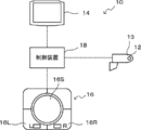
- FIG. 1 is a view showing a schematic configuration of a vehicle viewing device according to an embodiment of the present invention. It is a block diagram showing composition of a control system of vision equipment for vehicles concerning this embodiment. It is a figure for demonstrating the image for visual recognition which cuts out and produces
- FIG. 1A is a view showing an example of a vehicle mounting position of a visual recognition device for a vehicle according to an embodiment of the present invention
- FIG. 1B is a view showing a schematic configuration of the visual recognition device for a vehicle.
- the rear side camera 12 is installed outside at a vehicle front end of a vertically middle portion of a side door (front side door, not shown) of the vehicle and captures an image of the rear side of the vehicle.
- the rear side camera 12 is provided in a substantially rectangular box-shaped box-like housing 13 as a support, and a lens is disposed to the side of the rear side of the vehicle to photograph the rear side of the vehicle.
- the vehicle width direction inner side end portion of the housing 13 is attached to the side door, and the housing 13 is supported by the side door (vehicle body side) so as to be rotatable in the longitudinal direction of the vehicle.
- the housing 13 may be attached to another position such as a front fender instead of the side door.
- the monitor 14 is provided near the lower end of the front pillar, and mainly displays a photographed image of the rear side camera 12 as a visual recognition image. That is, the rear side of the vehicle as the periphery of the vehicle can be visually recognized by checking the monitor 14 instead of the outer mirror.
- the monitors 14 are respectively provided corresponding to the left and right of the vehicle.
- the operation unit 16 instructs the display position of the image displayed on the monitor 14, that is, the change of the visual range in the rear side.
- the operation unit 16 is, for example, a switch or a sensor for instructing change of the visible range in the vehicle width direction, change instruction in the vertical direction of the vehicle, etc., and the monitor 14 (left or right) to change the visible range.
- a switch or the like for instructing is provided. Specifically, it includes a left switch 16L and a right switch 16R for instructing a direction corresponding to the monitor 14 that changes the visible range, and a direction instructing unit 16S for instructing a changing direction.
- the control device 18 is provided corresponding to each of the left and right sides of the vehicle, and performs display control of the photographed images of the left and right rear side cameras 12.
- the control device 18 changes the visible range of the rear side of the vehicle at the time of reverse movement to make it easier to visually recognize an obstacle on the lower side of the vehicle, and the visible range in conjunction with the operation of the turn signal. It is also possible to further perform turn interlocking control or the like which is changed to make it easier to visually recognize the rear side of the vehicle.
- FIG. 2 is a block diagram showing a configuration of a control system of the vehicle viewing device 10 according to the present embodiment.
- the control device 18 is configured of a microcomputer in which a CPU 18A, a ROM 18B, a RAM 18C, and an I / O (input / output interface) 18D are connected to a bus 18E.
- the ROM 18 ⁇ / b> B stores various programs such as a vehicle viewing control program for performing display control for displaying a rear side photographed image of the rear side camera 12 on the monitor 14.
- the program stored in the ROM 18B is expanded on the RAM 18C and executed by the CPU 18A, whereby display control on the monitor 14 is performed.
- the I / O 18D is connected to an operation unit 16, a rear side camera 12, and a monitor 14 for instructing a change in the visible range and the like.
- the operation unit 16 outputs a change instruction signal to the control device 18 when an instruction to change the visible range on the rear side is issued by the occupant.
- the operation unit 16 includes the above-described left switch 16L, right switch 16R, and direction instructing unit 16S illustrated in FIG. 1B. That is, the left switch 16L or the right switch 16R instructs a direction (left or right) corresponding to the monitor 14 to change the visible range, and the direction indication unit 16S changes the visible direction (vehicle width direction and vehicle vertical direction) To direct.
- the operation unit 16 is provided with a vibration motor 16M as a vibration generation unit as shown by a dotted line in FIG. 2 and makes it possible to notify the occupant of various information by vibrating the operation unit 16 by the vibration motor 16M. May be
- the rear side camera 12 obtains a rear side photographed image by photographing the rear side of the vehicle.
- the rear side photographed image obtained by the photographing is output to the control device 18 as the photographing result of the rear side camera 12.
- the monitor 14 displays the rear side photographed image photographed by the rear side camera 12 according to the control of the control device 18.
- control device 18 performs display control on the monitor 14 based on the photographing result of the rear side camera 12, and when the change of the visual range in the rear side is instructed by the operation unit 16, the monitor 14 Control to change the display position (the visible range on the rear side) of
- the control device 18 may perform display control of the left and right monitors 14 with one control device 18 or may be provided in a pair corresponding to the left and right of the vehicle. When a pair of control devices 18 are provided corresponding to the left and right, the other control devices 18 may be connected to the respective I / Os 18D so as to enable mutual communication.
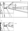
- FIG. 3 is a view for explaining a visual recognition image generated from the photographed image 30. As shown in FIG.
- the rear side camera 12 photographs the rear side of the vehicle, and a partial image shown by a dotted line in FIG. Cut out 32. Then, the cut out partial image 32 is displayed on the monitor 14 as the image 34 for visual recognition. That is, in the vehicle viewing device 10 according to the present embodiment, in order to display the partial image 32 of the partial range of the captured image 30, the viewing range can be changed by changing the cutout position. The change of the visible range is performed by operating the operation unit 16.
- the direction (left or right) for changing the visible range is selected by operating the left switch 16L or the right switch 16R, and the direction indication unit 16S is operated to change the visible range changing direction (vehicle width direction and Indicate the vertical direction of the vehicle).
- the control device 18 changes the position of the partial image 32 cut out in the direction operated by the operation unit 16 from the position of the current partial image 32 of the photographed image 30 and displays the visual recognition image 34 on the monitor 14. That is, the visual recognition image 34 displayed on the monitor 14 is sequentially moved and displayed in the direction indicated by the direction indication unit 16S.
- the movement limit is used. It is intended to notify that there is.
- the end of the captured image 30 is an example of the notification method of the movement limit
- the cutout position of the partial image 32 is changed
- the end of the partial image 32 is an end of the captured image 30.
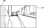
- the notification image showing that it is the movement limit is displayed.
- the notification image may display a visual recognition image 34 in which a band-shaped image 36 (for example, a band-shaped image such as a red line) is added to a portion corresponding to the movement limit of the partial image 32 .
- the non-display area 38 may be provided in the direction corresponding to the movement limit of the partial image 32.
- the non-display area 38 may be provided by narrowing the display range by the mask image.
- the non-display area 38 may be provided by narrowing the display range by compressing the image.
- the photographed image 30 in FIGS. 3 to 6 is the partial image 32 and the visual image 34 in the photographed image 30.
- the image is shown as a mirror-transformed image in order to make the relationship with.
- the method of informing the movement limit of the partial image is not limited to the above display, and may be informing by light or sound. Alternatively, notification may be made by combining display, light, and sound as appropriate.
- the notification image is moved by ending the display of the notification image when a predetermined time has elapsed since the notification image was displayed, or when the end of the change of the visible range is instructed. It is prevented that the notification of the limit is continued unnecessarily.
- the change of the visible range is not limited to the case of being instructed by the operation unit 16, and for example, the reverse interlock control to change the visible range interlocking with the above-described retraction or the visual range interlocked with the turning
- a predetermined condition for performing the swing interlock control to be performed may be satisfied.
- the predetermined conditions for performing the reverse interlocking control and the turning interlocking control are, for example, conditions predetermined by the direction indicator, the shift position, the vehicle speed, and the like, and known conditions can be applied.
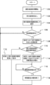
- FIG. 7 is a flowchart illustrating an example of the flow of processing performed by the control device 18 of the vehicle viewing device 10 according to the present embodiment. The process in FIG. 7 will be described as starting when an ignition switch (not shown) is turned on and ending when it is turned off. Further, the processing of FIG. 7 is performed by the CPU 18A developing and executing the vehicle viewing control program stored in the ROM 18B in the RAM 18C.
- step 100 the CPU 18A starts acquisition of a photographed image photographed by the rear side camera 12 and shifts to step 102. That is, the imaging results of the rear side camera 12 are sequentially acquired.
- step 102 the CPU 18 ⁇ / b> A cuts out the partial image 32 from the photographed image 30 and shifts to step 104.
- the partial image at this time may be a partial image of a predetermined default position in the captured image, or may be a partial image of a position previously instructed before IG off.
- step 104 the CPU 18A mirror-transforms the cut out partial image 32, and displays it on the monitor 14 as the image 34 for visual recognition as shown in FIG. Note that the partial image 32 may be cut out after mirror image conversion of the captured image 30 instead of performing mirror image conversion on the partial image 32.
- step 106 the CPU 18A determines whether or not the change of the visible range is made. For example, it is determined whether or not the change of the visible range is instructed by operating the operation unit 16, and the process waits until the determination is affirmed, and the process proceeds to step 108. Note that instead of whether or not the change of the visible range is instructed by the operation unit 16, it may be determined whether a predetermined condition for performing the reverse interlocking control or the turning interlocking control is satisfied. Alternatively, whether at least one of the instruction to change the visual recognition range by the operation unit 16 and the instruction to change the visual recognition range based on the establishment of a predetermined condition for performing interlocking control (at least one of reverse interlock control and turning interlock control) has been performed It may be determined whether or not.
- step 108 the CPU 18A controls the monitor 14 to change the cutout position of the partial image 32 according to the instruction and display the image 34 for visual recognition, and the process proceeds to step 110.
- step 110 the CPU 18A determines whether the end of the partial image 32 has reached the end of the captured image 30 as the movement limit. If the determination is negative, the process proceeds to step 112, and if the determination is affirmative, the process proceeds to step 114.
- step 112 the CPU 18A controls so that the partial image 32 changed in accordance with the instruction is mirror-image transformed and displayed on the monitor 14 as the visual recognition image 34, and the process proceeds to step 106 to repeat the above-described processing.
- step 114 the CPU 18A controls the partial image 32 changed in accordance with the instruction to be mirror-image converted and displayed on the monitor 14 as the visual recognition image 34. . That is, the movement limit can be notified by displaying the notification image.
- the notification method of the movement limit is notified by displaying the image for visual recognition in which the notification image is added to the partial image 32 as described above, but is also notified using light or sound. It is also good.
- step 116 the CPU 18A determines whether to end notification of the movement limit. The determination determines whether or not a predetermined time has elapsed since the notification image was displayed, and whether or not the end of the change of the visible range is instructed, and waits until the determination is affirmed Then, the process proceeds to step 118.
- step 118 the CPU 18A ends the notification of the movement limit, returns to step 106, and repeats the above-described processing.
- the change instruction of the visible range by the operation unit 16 is continued in a state where the notification image is displayed.
- the display state of the notification image may be changed.
- at least one of enlargement, blinking and color change of the area of the notification image can be applied.
- the area displaying the notification image may be expanded. As an example of expanding the area in which the notification image is displayed, as shown in FIG.
- the display area of the band-shaped image 36 as the notification image may be expanded in the arrow direction.
- the non-display area 38 as the notification image may be enlarged in the arrow direction.
- the display state of the notification image not only enlargement but also blinking of the notification image according to the continuation time of the change instruction of the visual recognition range by the operation unit 16 (flashing earlier as the continuation time of change instruction becomes longer)
- the display state such as color change may be simultaneously changed.
- the instruction is continued when the notification image is displayed and the instruction is continued. As the duration of time is longer, the area for displaying the notification image may be enlarged.
- a vibration motor 16M or the like may be provided in the operation unit 16, and notification may be given by causing the operation unit 16 to generate vibration.
- the direction motor 16S is provided with the vibration motor 16 as shown by a dotted line in FIG. 2, and the vibration motor 16M is operated when the cutout position of the partial image reaches the end of the photographed image as the movement limit. By doing this, the direction indicating unit 16S may be vibrated to notify that it is the movement limit.
- the movement limit for changing the cutout position of the partial image 32 the case where the end of the partial image 32 reaches the end of the captured image 30 has been described as an example, but in the present invention Absent.
- the movement limit may be several pixels before the cutout position of the partial image 32 reaches the end of the captured image 32.
- photographs the vehicle rear side as a vehicle periphery and it visually recognizes was demonstrated as an example, it does not restrict to this.
- control apparatus 18 in said embodiment was demonstrated as a process of software, it is not restricted to this.
- processing may be performed by hardware, or processing combining both hardware and software may be used.
- control device 18 in the above embodiment may be stored in a storage medium as a program and distributed.
Landscapes
- Engineering & Computer Science (AREA)
- Multimedia (AREA)
- Mechanical Engineering (AREA)
- Signal Processing (AREA)
- Closed-Circuit Television Systems (AREA)
Abstract
撮影画像から部分画像を切り出して視認用画像(34)としてモニタに表示し、撮影画像(30)から部分画像(32)の切出し位置を変更して視認範囲を変更する際には、撮影画像(30)における移動限度としての端部まで部分画像(32)の位置が変更された場合に、部分画像(32)の移動限度に対応する部分に帯状画像(36)(例えば、赤線等の帯状画像)を付加した視認用画像(34)を表示する。
Description
本発明は、車両周辺を視認するために車両周辺を撮影して撮影画像を表示する車両用視認装置に関する。
車両周辺の撮影画像を表示する車両用視認装置を光学ミラーの代わりとして車両に搭載する技術が知られている。
このような車両用視認装置では、カメラ等によって撮影することで得られる撮影画像のうちの一部の範囲の部分画像を表示して、光学ミラーのような視認性を提供するものがある。この場合、部分画像を表示するので、視認範囲を変更する際には、撮影画像から部分画像を切り出す位置を変更することで視認範囲を変更することができる。
しかしながら、視認範囲を変更する際に元からどの程度ずれたかや、変更可能な視認範囲等を認識し難い、という問題がある。
そこで、特開2010-163104号公報では、撮影画像の範囲を示す枠線、及び切り出した画像の範囲を示す枠線をインジケータとして、切り出した部分画像と共に表示するようにしている。インジケータを表示することで、変更した視認範囲が元からどの程度ずれたかや、変更可能な視認範囲等をインジケータにより容易に認識することができる。
しかしながら、特開2010-163104号公報では、視認範囲を変更する際に、インジケータにより切り出す範囲が撮影画像のどの範囲であるか大まかに認識可能であるが、切出し範囲が撮影画像の端部等の移動限度まで移動した場合、移動限度であることが分り難い。この場合、さらに続けて同じ方向に移動させることができず、移動限度への到達に気づかずに、不便さや違和感を与えることがあり得るため改善の余地がある。
本発明は、上記事実を考慮して成されたもので、部分画像の移動限度に気付かないことによる視認範囲変更時の不便性を解消することを目的とする。
上記目的を達成するために本開示の第1の態様は、車両周辺を乗員が視認するための視認用画像を表示する表示部と、車両周辺を撮影した撮影画像から切り出した部分画像を前記視認用画像として表示すると共に、前記視認用画像の視認範囲の変更が指示された場合に、指示に応じて前記部分画像の切出し位置を変更して前記視認用画像を表示するように前記表示部を制御する制御部と、前記制御部によって前記部分画像の切出し位置が、前記撮影画像における予め定めた移動限度まで変更された場合に、前記移動限度であることを報知する報知部と、を備える。
本開示の第1の態様によれば、表示部には、車両周辺を乗員が視認するための視認用画像が表示され、乗員が表示された視認用画像を確認することで車両周辺を視認することが可能とされている。
制御部では、車両周辺を撮影した撮影画像から切り出した部分画像を視認用画像として表示すると共に、視認用画像の視認範囲の変更が指示された場合に、指示に応じて部分画像の切出し位置を変更して視認用画像を表示するように表示部が制御される。これにより、表示部への視認用画像の表示を行って、視認範囲の変更が指示された場合に、指示に応じて視認範囲を変更することができる。
そして、報知部では、制御部によって部分画像の切出し位置が撮影画像における予め定めた移動限度まで変更された場合に、移動限度であることが報知される。すなわち、部分画像の移動限度を報知するので、部分画像の移動限度に気付かないことによる視認範囲変更時の不便性を解消することができる。
なお、報知部は、本開示の第2の態様のように、移動限度の報知から予め定めた時間経過した場合、及び視認範囲の変更の終了が指示された場合の少なくとも一方の場合に、移動限度の報知を終了してもよい。これにより、移動限度の報知が不必要に継続されることを防止することができる。
また、本開示の第3の態様のように、視認範囲の変更を指示するための指示部を更に備えてもよい。これにより、乗員が部分画像の移動限度に気付かずに指示部によって切出し範囲の変更を指示し続けることがなくなる。
また、本開示の第4の態様のように、制御部は、車両の旋回及び車両の後退の少なくとも一方に連動して視認用画像の視認範囲を変更する場合の予め定めた条件の成立を視認用画像の変更の指示としてもよい。これにより、旋回に連動して視認範囲を変更する旋回連動制御や、後退に連動して視認範囲を変更する後退連動制御時においても、部分画像の切出し位置が移動限度に到達した場合に報知することができる。
また、本開示の第5の態様のように、報知部は、表示部に表示された部分画像の移動限度に対応する部分に、移動限度であることを表す報知画像を表示することによって移動限度であることを報知してもよい。すなわち、報知画像により移動限度を報知することができる。
また、本開示の第6の態様のように、報知部は、部分画像の前記移動限度に対応する部分に、移動限度であることを表す報知画像を表示し、当該報知画像を表示した状態で指示が継続された場合、指示の継続時間に応じて、前記報知画像の表示状態を変化させてもよい。これにより、乗員が移動限度に気付かない場合に、報知画像の表示状態を変化させることで気付かせることが可能となる。
さらに、本開示の第7の態様のように、報知部は、視認範囲の変更を指示するための指示部に振動を発生させる振動発生部を含み、振動発生部により指示部を振動させることで、移動限度であることを報知してもよい。指示部を操作する乗員の手に振動を伝達して移動限度であることを確実に報知することが可能となる。
以上説明したように本発明によれば、部分画像の移動限度に気付かないことによる視認範囲変更時の不便性を解消することができる、という効果がある。
以下、図面を参照して本発明の実施の形態の一例を詳細に説明する。図1Aは、本発明の実施の形態に係る車両用視認装置の車両搭載位置例を示す図であり、図1Bは車両用視認装置の概略構成を示す図である。
本実施形態に係る車両用視認装置10は、後側方カメラ12、表示部としてのモニタ14、指示部としての操作部16、並びに、制御部及び報知部としての制御装置18が車両の左右に対応してそれぞれ設けられている。
後側方カメラ12は、車両のサイドドア(フロントサイドドア、図示省略)の上下方向中間部の車両前側端に外側に設置されて車両後側方を撮影する。後側方カメラ12は、支持体としての略直方体形箱状の筐体13に設けられており、レンズが車両後側方に向けて配置され、車両の後側方を撮影する。筐体13の車幅方向内側端部は、サイドドアに取付けられており、筐体13がサイドドア(車体側)に車両前後方向に回動可能に支持されている。なお、筐体13は、サイドドアではなく、フロントフェンダ等の他の位置に取り付ける形態としてもよい。
モニタ14は、フロントピラーの下端付近に設けられ、後側方カメラ12の撮影画像を視認用画像として主に表示する。すなわち、アウターミラーの代わりとされ、モニタ14を確認することにより、車両周辺としての車両後側方を視認することができる。モニタ14は、車両の左右に対応してそれぞれ設けられている。
操作部16は、モニタ14に表示される画像の表示位置、すなわち、後側方の視認範囲の変更の指示等を行う。操作部16は、例えば、視認範囲の車幅方向への変更指示や、車両上下方向への変更指示等を行うためのスイッチやセンサ、視認範囲を変更する対象のモニタ14(左または右)を指示するためのスイッチ等を備える。具体的には、視認範囲を変更するモニタ14に対応する方向を指示するための左スイッチ16L及び右スイッチ16Rと、変更方向を指示するための方向指示部16Sと、を含む。
制御装置18は、車両の左右のそれぞれに対応して設けられており、左右各々の後側方カメラ12の撮影画像の表示制御を行う。なお、制御装置18は、後退時に車両後側方の視認範囲を変更して車両側方下側の障害物を視認し易くする後退連動制御や、方向指示器の操作に連動して視認範囲を変更して車両後側方を視認し易くする旋回連動制御等を更に行うようにしてもよい。
続いて、本実施形態に係る車両用視認装置10の制御系の構成について説明する。図2は、本実施形態に係る車両用視認装置10の制御系の構成を示すブロック図である。
制御装置18は、CPU18A、ROM18B、RAM18C、及びI/O(入出力インタフェース)18Dがそれぞれバス18Eに接続されたマイクロコンピュータで構成されている。
ROM18Bには、後側方カメラ12の後側方撮影画像をモニタ14に表示するための表示制御を行うための車両用視認制御プログラム等の各種プログラムが記憶されている。ROM18Bに記憶されたプログラムをRAM18Cに展開してCPU18Aが実行することにより、モニタ14への表示制御が行われる。
I/O18Dには、視認範囲の変更等を指示するための操作部16、後側方カメラ12、及びモニタ14が接続されている。
操作部16は、後側方の視認範囲の変更の指示等が乗員によって行われると、変更指示信号を制御装置18に出力する。操作部16は、具体的には、図1Bに示す上述の左スイッチ16L、右スイッチ16R、及び方向指示部16Sを有する。すなわち、左スイッチ16Lまたは右スイッチ16Rによって視認範囲を変更するモニタ14に対応する方向(左または右)を指示し、方向指示部16Sによって視認範囲の変更方向(車幅方向及び車両上下方向)を指示する。なお、操作部16は、図2の点線で示すように、振動発生部としての振動用モータ16Mを設けて、振動用モータ16Mにより操作部16を振動させることで乗員に各種情報を報知可能にしてもよい。
後側方カメラ12は、車両後側方を撮影することによって後側方撮影画像を得る。撮影によって得られた後側方撮影画像は、後側方カメラ12の撮影結果として制御装置18に出力する。
モニタ14は、後側方カメラ12によって撮影された後側方撮影画像を制御装置18の制御に従って表示する。
そして、制御装置18は、後側方カメラ12の撮影結果に基づいて、モニタ14への表示制御を行うと共に、操作部16によって後側方の視認範囲の変更が指示された場合に、モニタ14の表示位置(後側方の視認範囲)を変更する制御を行う。
なお、制御装置18は、1つの制御装置18で左右のモニタ14の表示制御を行ってもよいし、車両の左右に対応して一対設けられてもよい。左右に対応して一対の制御装置18を設ける場合には、それぞれ相互通信可能なようにそれぞれのI/O18Dに他方の制御装置18を接続してもよい。
ここで、制御装置18によるモニタ14への後側方カメラ12の撮影画像の表示方法について詳細に説明する。図3は、撮影画像30から生成する視認用画像を説明するための図である。
本実施形態に係る車両用視認装置10では、図3に示すように、後側方カメラ12によって車両の後側方を撮影し、撮影によって得られる撮影画像30から図3の点線で示す部分画像32を切り出す。そして、切り出した部分画像32を視認用画像34としてモニタ14に表示する。すなわち、本実施形態に係る車両用視認装置10では、撮影画像30の一部の範囲の部分画像32を表示するため、切出し位置を変更することで、視認範囲の変更が可能とされている。視認範囲の変更は、操作部16を操作することで行われる。具体的には、視認範囲を変更する方向(左または右)を左スイッチ16Lまたは右スイッチ16Rの操作により選択して、方向指示部16Sを操作することで視認範囲の変更方向(車幅方向及び車両上下方向)を指示する。これにより、制御装置18が、撮影画像30の現在の部分画像32の位置から操作部16によって操作された方向に切り出す部分画像32の位置を変更して視認用画像34をモニタ14に表示する。すなわち、モニタ14に表示される視認用画像34は、方向指示部16Sの指示方向に順次移動して表示される。
ここで、図4に示すように、部分画像32の切出し位置が撮影画像30の端部まで到達すると、撮影画像30の端部に到達する前までの移動方向と同じ方向へはこれ以上移動することができなくなり、視認用画像34の移動が停止する。このとき、視認用画像34の移動が単に停止されるだけでは、乗員が撮影画像30の端部まで部分画像32が到達したことに気付き難く、不便さや違和感を与えることがあり得る。
そこで、本実施形態では、部分画像32の切出し位置を変更して視認範囲を変更する際に、撮影画像30における予め定めた移動限度まで部分画像32の位置が変更された場合に、移動限度であることを報知するようになっている。
具体的には、本実施形態では、撮影画像30の端部を移動限度の報知方法の一例とし、部分画像32の切出し位置を変更し、撮影画像30の端部に部分画像32の端部が到達した場合に、移動限度であることを表す報知画像を表示する。報知画像は、例えば、図5に示すように、部分画像32の移動限度に対応する部分に帯状画像36(例えば、赤線等の帯状画像)を付加した視認用画像34を表示してもよい。或いは、図6に示すように、部分画像32の移動限度に対応する方向に非表示領域38を設けてもよい。図6では、非表示領域38として、移動限度に対応する端部側の画像の表示範囲を狭くした例を示す。表示範囲を狭くする方法としては、マスク画像によって表示範囲を狭くして非表示領域38を設けてもよい。また、画像を圧縮することで表示範囲を狭くして非表示領域38を設けてもよい。
なお、視認用画像34は、光学ミラーと同様の像をモニタ14に表示するために鏡像変換を行うので、図3~6における撮影画像30は、撮影画像30における部分画像32と視認用画像34との関係を分かりやすくするために、鏡像変換された画像として示す。
また、部分画像の移動限度を報知する方法としては、上述の表示に限るものではなく、光や音によって報知してもよい。或いは、表示、光、及び音を適宜組み合わせて報知してもよい。
また、本実施形態では、報知画像は、報知画像を表示してから予め定めた時間経過、或いは、視認範囲の変更の終了が指示された場合に、報知画像の表示を終了することにより、移動限度の報知が不必要に継続されることを防止している。
また、視認範囲の変更は、操作部16によって指示された場合に限るものではなく、例えば、上述した後退に連動して視認範囲を変更する後退連動制御や、旋回に連動して視認範囲を変更する旋回連動制御を行うための予め定めた条件が成立した場合でもよい。後退連動制御や旋回連動制御において予め定めた変更量の視認範囲を変更する際に、上述の移動限度まで部分画像の切出し位置が変更された場合には、報知画像の表示等によって移動限度であることを報知してもよい。ここで、後退連動制御や旋回連動制御を行うための予め定めた条件は、例えば、方向指示器、シフト位置、車速等によって予め定めた条件であり、周知の条件を適用可能である。
続いて、上述のように構成された本実施形態に係る車両用視認装置10の制御装置18で行われる具体的な処理について説明する。図7は、本実施形態に係る車両用視認装置10の制御装置18で行われる処理の流れの一例を示すフローチャートである。なお、図7の処理は、図示しないイグニッションスイッチがオンされた場合に開始し、オフされた場合に終了するものとして説明する。また、図7の処理は、ROM18Bに記憶された車両用視認制御プログラムをCPU18AがRAM18Cに展開して実行することにより行われる。
まず、ステップ100では、CPU18Aが、後側方カメラ12によって撮影された撮影画像を取得開始してステップ102へ移行する。すなわち、後側方カメラ12の撮影結果を順次取得する。
ステップ102では、CPU18Aが、撮影画像30から部分画像32を切り出してステップ104へ移行する。なお、この時の部分画像は撮影画像中の予め定めたデフォルトの位置の部分画像でもよいし、IGオフ前に前回指示された位置の部分画像でもよい。
ステップ104では、CPU18Aが、切り出した部分画像32を鏡像変換して、図3に示すように、視認用画像34としてモニタ14に表示してステップ106へ移行する。なお、部分画像32を鏡像変換するのではなく、撮影画像30を鏡像変換してから部分画像32を切り出してもよい。
ステップ106では、CPU18Aが、視認範囲の変更であるか否かを判定する。該判定は、例えば、操作部16が操作されて視認範囲の変更が指示されたか否かを判定し、該判定が肯定されるまで待機してステップ108へ移行する。なお、操作部16によって視認範囲の変更が指示されたか否かの代わりに、後退連動制御または旋回連動制御を行う予め定めた条件が成立したか否かを判定してもよい。或いは、操作部16による視認範囲の変更指示、及び連動制御(後退連動制御及び旋回連動制御の少なくとも一方)を行う予め定めた条件の成立による視認範囲の変更指示の少なくとも一方の指示が行われたか否かを判定してもよい。
ステップ108では、CPU18Aが、指示に応じて部分画像32の切出し位置を変更して視認用画像34を表示するようにモニタ14を制御してステップ110へ移行する。
ステップ110では、CPU18Aが、部分画像32の端部が移動限度としての撮影画像30の端部に到達したか否かを判定する。該判定が否定された場合にはステップ112へ移行し、肯定された場合にはステップ114へ移行する。
ステップ112では、CPU18Aが、指示に応じて変更した部分画像32を鏡像変換して視認用画像34としてモニタ14に表示するように制御してステップ106へ移行して上述の処理を繰り返す。
一方、ステップ114では、CPU18Aが、指示に応じて変更した部分画像32を鏡像変換して視認用画像34としてモニタ14に表示するように制御すると共に、移動限度を報知してステップ116へ移行する。すなわち、報知画像を表示することによって移動限度を報知することができる。これにより、操作部16を操作して視認範囲を変更している場合には、乗員が部分画像32の移動限度に気付かずに操作し続けることがなくなる。なお、移動限度の報知方法は、本実施形態では、上述したように報知画像を部分画像32に付加した視認用画像を表示することにより報知するが、併せて光や音を用いて報知してもよい。
ステップ116では、CPU18Aが移動限度の報知を終了するか否かを判定する。該判定は、報知画像を表示してから予め定めた時間経過したか否か、及び、視認範囲の変更の終了が指示されたか否かの少なくとも一方を判定し、該判定が肯定されるまで待機してステップ118へ移行する。
ステップ118では、CPU18Aが移動限度の報知を終了してステップ106に戻って上述の処理を繰り返す。
このように処理を行うことで、モニタ14に表示された視認用画像34の視認範囲を変更する場合に、切り出す部分画像32の位置を変更して、移動限度とされた撮影画像の端部に到達した場合に、移動限度であることが報知される。これにより、部分画像の移動限度に気付かないことによる視認範囲変更時の不便性を解消することができる。
なお、本実施形態において、操作部16が操作されることで視認範囲を変更して報知画像を表示する際に、報知画像を表示した状態で操作部16による視認範囲の変更指示が継続された場合に、報知画像の表示状態を変化させてもよい。表示状態の変化例としては、報知画像の領域の拡大、点滅、及び色変化の少なくとも1つを適用できる。報知画像の表示領域を拡大する場合には、例えば、操作部16による視認範囲の変更指示の継続時間が長くなるほど、報知画像を表示する領域を拡大してもよい。報知画像を表示する領域を拡大する例としては、図8Aに示すように、報知画像としての帯状画像36の表示領域を矢印方向に拡大してもよい。また、図8Bに示すように、報知画像としての非表示領域38を矢印方向に拡大してもよい。これにより、移動限度に乗員が気付かない場合に、報知画像の領域を拡大することで気付かせることが可能となる。また、報知画像の表示状態の変化例としては拡大だけではなく、操作部16による視認範囲の変更指示の継続時間に応じて、報知画像の点滅(変更指示の継続時間が長くなるほど早い点滅等)や色変化などの表示状態を同時に変化させてもよい。また、同様に、旋回連動制御や後退連動制御の予め定めた条件が成立した場合を視認範囲の変更の指示とする場合についても、報知画像が表示された状態で指示が継続された場合に指示の継続時間が長くなるほど、報知画像を表示する領域を拡大してもよい。
また、上記の実施形態では、表示によって部分画像の移動限度であることを報知する例を説明し、報知方法として音や光等を用いてよいことを説明したが、報知方法はこれらに限るものではない。例えば、操作部16に振動用モータ16M等を設けて、操作部16に振動を発生させることで報知してもよい。詳細には、方向指示部16Sに振動用モータ16を図2の点線で示すように設け、部分画像の切出し位置が移動限度としての撮影画像の端部に到達した場合に振動用モータ16Mを作動することで方向指示部16Sを振動させて移動限度であることを報知してもよい。これにより、操作部16を操作する乗員の手に振動を伝達して移動限度であることを確実に報知することが可能となる。また、振動用モータ16による振動、報知画像、光、及び音による移動限度の報知は適宜組み合わせることにより、移動限度であることを更に確実に報知することが可能となる。
また、上記の実施形態では、部分画像32の切出し位置を変更する移動限度として、撮影画像30の端部に部分画像32の端部が到達した場合を一例として説明したが、これに限るものではない。例えば、部分画像32の切出し位置が、撮影画像32の端部に到達する数画素手前を移動限度としてもよい。
また、上記の実施形態では、車両周辺として車両後側方を撮影して視認する車両用視認装置を一例として説明したが、これに限るものではない。例えば、車両側方や、前方、後方等の他の方向を撮影して視認する車両用視認装置を適用してもよい。
また、上記の実施形態における制御装置18で行われる処理は、ソフトウエアの処理として説明したが、これに限るものではない。例えば、ハードウエアで行う処理としてもよいし、ハードウエアとソフトウエアの双方を組み合わせた処理としてもよい。
また、上記の実施形態における制御装置18で行われる処理は、プログラムとして記憶媒体に記憶して流通させるようにしてもよい。
さらに、本発明は、上記に限定されるものでなく、上記以外にも、その主旨を逸脱しない範囲内において種々変形して実施可能であることは勿論である。
2016年5月19日に出願された日本国特許出願2016-100671号の開示は、その全体が参照により本明細書に取り込まれる。
Claims (7)
- 車両周辺を乗員が視認するための視認用画像を表示する表示部と、
車両周辺を撮影した撮影画像から切り出した部分画像を前記視認用画像として表示すると共に、前記視認用画像の視認範囲の変更が指示された場合に、指示に応じて前記部分画像の切出し位置を変更して前記視認用画像を表示するように前記表示部を制御する制御部と、
前記制御部によって前記部分画像の切出し位置が、前記撮影画像における予め定めた移動限度まで変更された場合に、前記移動限度であることを報知する報知部と、
を備えた車両用視認装置。 - 前記報知部は、前記移動限度の報知から予め定めた時間経過した場合、及び前記視認範囲の変更の終了が指示された場合の少なくとも一方の場合に、前記移動限度の報知を終了する請求項1に記載の車両用視認装置。
- 前記視認範囲の変更を指示するための指示部を更に備えた請求項1又は請求項2に記載の車両用視認装置。
- 前記制御部は、車両の旋回及び車両の後退の少なくとも一方に連動して前記視認用画像の視認範囲を変更する場合の予め定めた条件の成立を前記視認用画像の変更の指示とする請求項1~3の何れか1項に記載の車両用視認装置。
- 前記報知部は、前記表示部に表示された前記部分画像の前記移動限度に対応する部分に、前記移動限度であることを表す報知画像を表示することによって前記移動限度であることを報知する請求項1~4の何れか1項に記載の車両用視認装置。
- 前記報知部は、前記部分画像の前記移動限度に対応する部分に、前記移動限度であることを表す報知画像を表示し、当該報知画像を表示した状態で指示が継続された場合、指示の継続時間に応じて、前記報知画像の表示状態を変化させる請求項1~4の何れか1項に記載の車両用視認装置。
- 前記報知部は、前記視認範囲の変更を指示するための指示部に振動を発生させる振動発生部を含み、前記振動発生部により前記指示部を振動させることで、前記移動限度であることを報知する請求項1~6の何れか1項に記載の車両用視認装置。
Priority Applications (1)
| Application Number | Priority Date | Filing Date | Title |
|---|---|---|---|
| US16/301,138 US20190135191A1 (en) | 2016-05-19 | 2017-05-12 | Viewing device for vehicle |
Applications Claiming Priority (2)
| Application Number | Priority Date | Filing Date | Title |
|---|---|---|---|
| JP2016-100671 | 2016-05-19 | ||
| JP2016100671A JP6609513B2 (ja) | 2016-05-19 | 2016-05-19 | 車両用視認装置 |
Publications (1)
| Publication Number | Publication Date |
|---|---|
| WO2017199888A1 true WO2017199888A1 (ja) | 2017-11-23 |
Family
ID=60326255
Family Applications (1)
| Application Number | Title | Priority Date | Filing Date |
|---|---|---|---|
| PCT/JP2017/018095 Ceased WO2017199888A1 (ja) | 2016-05-19 | 2017-05-12 | 車両用視認装置 |
Country Status (3)
| Country | Link |
|---|---|
| US (1) | US20190135191A1 (ja) |
| JP (1) | JP6609513B2 (ja) |
| WO (1) | WO2017199888A1 (ja) |
Cited By (4)
| Publication number | Priority date | Publication date | Assignee | Title |
|---|---|---|---|---|
| CN109624858A (zh) * | 2019-01-04 | 2019-04-16 | 斑马网络技术有限公司 | 外后视镜的图像显示方法及装置 |
| EP3572284A1 (en) * | 2018-05-24 | 2019-11-27 | Toyota Jidosha Kabushiki Kaisha | Vehicle surroundings display device |
| US10857943B2 (en) | 2018-09-05 | 2020-12-08 | Toyota Jidosha Kabushiki Kaisha | Vehicle surroundings display device |
| US11244173B2 (en) | 2018-05-11 | 2022-02-08 | Toyota Jidosha Kabushiki Kaisha | Image display apparatus |
Families Citing this family (2)
| Publication number | Priority date | Publication date | Assignee | Title |
|---|---|---|---|---|
| US11405559B1 (en) * | 2021-02-19 | 2022-08-02 | Honda Motor Co., Ltd. | Systems and methods for live signal adjustment of a movable camera |
| DE102024119595A1 (de) * | 2024-07-10 | 2026-01-15 | Bayerische Motoren Werke Aktiengesellschaft | Sichtbereichseinstellungs-Hilfe für physischen oder virtuellen Außenspiegel im Fahrzeug |
Citations (7)
| Publication number | Priority date | Publication date | Assignee | Title |
|---|---|---|---|---|
| JP2004173152A (ja) * | 2002-11-22 | 2004-06-17 | Sony Corp | モニタリングシステムおよび方法並びにプログラムおよび記録媒体 |
| JP2004276803A (ja) * | 2003-03-17 | 2004-10-07 | Calsonic Kansei Corp | パーソナルコンピュータ車載装置 |
| JP2004336475A (ja) * | 2003-05-08 | 2004-11-25 | Sony Corp | 情報処理装置および方法、並びにプログラム |
| JP2010163104A (ja) * | 2009-01-16 | 2010-07-29 | Denso Corp | 車両用表示装置及びそれを備えた車両周辺視野表示システム |
| JP2010202988A (ja) * | 2009-02-27 | 2010-09-16 | Toyota Industries Corp | 紡機のニューマ装置 |
| JP2014011721A (ja) * | 2012-07-02 | 2014-01-20 | Olympus Imaging Corp | 撮像装置、撮像方法およびプログラム |
| JP2017015825A (ja) * | 2015-06-29 | 2017-01-19 | カシオ計算機株式会社 | サーバ装置、通信機器、サーバ装置の制御方法、およびプログラム |
Family Cites Families (6)
| Publication number | Priority date | Publication date | Assignee | Title |
|---|---|---|---|---|
| JP2008018760A (ja) * | 2006-07-11 | 2008-01-31 | Honda Motor Co Ltd | 運転支援装置 |
| KR101561913B1 (ko) * | 2009-04-17 | 2015-10-20 | 엘지전자 주식회사 | 이동 단말기의 영상 표시 방법 및 그 장치 |
| JP5696872B2 (ja) * | 2010-03-26 | 2015-04-08 | アイシン精機株式会社 | 車両周辺監視装置 |
| JP5329582B2 (ja) * | 2011-02-09 | 2013-10-30 | 本田技研工業株式会社 | 車両用周辺監視装置 |
| JP5682788B2 (ja) * | 2011-09-27 | 2015-03-11 | アイシン精機株式会社 | 車両周辺監視装置 |
| JP2014158257A (ja) * | 2013-01-18 | 2014-08-28 | Panasonic Corp | 通信装置及び通信システム |
-
2016
- 2016-05-19 JP JP2016100671A patent/JP6609513B2/ja active Active
-
2017
- 2017-05-12 WO PCT/JP2017/018095 patent/WO2017199888A1/ja not_active Ceased
- 2017-05-12 US US16/301,138 patent/US20190135191A1/en not_active Abandoned
Patent Citations (7)
| Publication number | Priority date | Publication date | Assignee | Title |
|---|---|---|---|---|
| JP2004173152A (ja) * | 2002-11-22 | 2004-06-17 | Sony Corp | モニタリングシステムおよび方法並びにプログラムおよび記録媒体 |
| JP2004276803A (ja) * | 2003-03-17 | 2004-10-07 | Calsonic Kansei Corp | パーソナルコンピュータ車載装置 |
| JP2004336475A (ja) * | 2003-05-08 | 2004-11-25 | Sony Corp | 情報処理装置および方法、並びにプログラム |
| JP2010163104A (ja) * | 2009-01-16 | 2010-07-29 | Denso Corp | 車両用表示装置及びそれを備えた車両周辺視野表示システム |
| JP2010202988A (ja) * | 2009-02-27 | 2010-09-16 | Toyota Industries Corp | 紡機のニューマ装置 |
| JP2014011721A (ja) * | 2012-07-02 | 2014-01-20 | Olympus Imaging Corp | 撮像装置、撮像方法およびプログラム |
| JP2017015825A (ja) * | 2015-06-29 | 2017-01-19 | カシオ計算機株式会社 | サーバ装置、通信機器、サーバ装置の制御方法、およびプログラム |
Cited By (5)
| Publication number | Priority date | Publication date | Assignee | Title |
|---|---|---|---|---|
| US11244173B2 (en) | 2018-05-11 | 2022-02-08 | Toyota Jidosha Kabushiki Kaisha | Image display apparatus |
| EP3572284A1 (en) * | 2018-05-24 | 2019-11-27 | Toyota Jidosha Kabushiki Kaisha | Vehicle surroundings display device |
| US10647260B2 (en) | 2018-05-24 | 2020-05-12 | Toyota Jidosha Kabushiki Kaisha | Vehicle surroundings display device |
| US10857943B2 (en) | 2018-09-05 | 2020-12-08 | Toyota Jidosha Kabushiki Kaisha | Vehicle surroundings display device |
| CN109624858A (zh) * | 2019-01-04 | 2019-04-16 | 斑马网络技术有限公司 | 外后视镜的图像显示方法及装置 |
Also Published As
| Publication number | Publication date |
|---|---|
| JP2017206155A (ja) | 2017-11-24 |
| US20190135191A1 (en) | 2019-05-09 |
| JP6609513B2 (ja) | 2019-11-20 |
Similar Documents
| Publication | Publication Date | Title |
|---|---|---|
| WO2017199888A1 (ja) | 車両用視認装置 | |
| US11052823B2 (en) | Vehicle rear monitoring system | |
| JP6683451B2 (ja) | 車両用視認装置 | |
| JP4254887B2 (ja) | 車両用画像表示システム | |
| JP7147255B2 (ja) | 画像表示装置 | |
| JP2016168877A (ja) | 車両用視認装置 | |
| JP2019116220A (ja) | 車両用視認装置 | |
| JP2017202741A (ja) | 車両用視認装置 | |
| CN105584417A (zh) | 车辆用视野辅助装置 | |
| JP5402047B2 (ja) | 死角表示装置 | |
| JP2019182348A (ja) | 画像表示装置 | |
| JP2017073040A (ja) | 車両用視認装置及び車両用視認制御プログラム | |
| JP2019040354A (ja) | 運転支援装置、および運転支援方法 | |
| JP2006246430A (ja) | 車両周辺監視装置 | |
| JP6555240B2 (ja) | 車両用撮影表示装置及び車両用撮影表示プログラム | |
| JP6602721B2 (ja) | 車両用視認装置 | |
| WO2019039348A1 (ja) | 車両用視認装置 | |
| JP2008182312A (ja) | 撮像画像表示装置 | |
| JP2010188926A (ja) | 車両後方表示装置および車両後方表示方法 | |
| WO2018123547A1 (ja) | 車両用視認装置 | |
| JP5825091B2 (ja) | 撮影領域明示装置 | |
| CN107972583B (zh) | 车辆用成像显示装置以及记录介质 | |
| JP2004304242A (ja) | 車外映像撮像装置 | |
| JP2004015439A (ja) | 車両用監視装置 | |
| JP3125259U (ja) | 車両ビデオ監視制御装置 |
Legal Events
| Date | Code | Title | Description |
|---|---|---|---|
| NENP | Non-entry into the national phase |
Ref country code: DE |
|
| 121 | Ep: the epo has been informed by wipo that ep was designated in this application |
Ref document number: 17799312 Country of ref document: EP Kind code of ref document: A1 |
|
| 122 | Ep: pct application non-entry in european phase |
Ref document number: 17799312 Country of ref document: EP Kind code of ref document: A1 |