WO2017199818A1 - 炭素含有固体燃料ガス化発電設備及びその炭素含有固体燃料の乾燥用ガスの調整方法 - Google Patents
炭素含有固体燃料ガス化発電設備及びその炭素含有固体燃料の乾燥用ガスの調整方法 Download PDFInfo
- Publication number
- WO2017199818A1 WO2017199818A1 PCT/JP2017/017738 JP2017017738W WO2017199818A1 WO 2017199818 A1 WO2017199818 A1 WO 2017199818A1 JP 2017017738 W JP2017017738 W JP 2017017738W WO 2017199818 A1 WO2017199818 A1 WO 2017199818A1
- Authority
- WO
- WIPO (PCT)
- Prior art keywords
- exhaust gas
- temperature
- gas
- furnace
- drying
- Prior art date
- Legal status (The legal status is an assumption and is not a legal conclusion. Google has not performed a legal analysis and makes no representation as to the accuracy of the status listed.)
- Ceased
Links
Images



Classifications
-
- C—CHEMISTRY; METALLURGY
- C10—PETROLEUM, GAS OR COKE INDUSTRIES; TECHNICAL GASES CONTAINING CARBON MONOXIDE; FUELS; LUBRICANTS; PEAT
- C10J—PRODUCTION OF PRODUCER GAS, WATER-GAS, SYNTHESIS GAS FROM SOLID CARBONACEOUS MATERIAL, OR MIXTURES CONTAINING THESE GASES; CARBURETTING AIR OR OTHER GASES
- C10J3/00—Production of combustible gases containing carbon monoxide from solid carbonaceous fuels
- C10J3/46—Gasification of granular or pulverulent flues in suspension
- C10J3/48—Apparatus; Plants
- C10J3/485—Entrained flow gasifiers
-
- B—PERFORMING OPERATIONS; TRANSPORTING
- B01—PHYSICAL OR CHEMICAL PROCESSES OR APPARATUS IN GENERAL
- B01D—SEPARATION
- B01D53/00—Separation of gases or vapours; Recovering vapours of volatile solvents from gases; Chemical or biological purification of waste gases, e.g. engine exhaust gases, smoke, fumes, flue gases, aerosols
- B01D53/34—Chemical or biological purification of waste gases
- B01D53/46—Removing components of defined structure
- B01D53/54—Nitrogen compounds
- B01D53/56—Nitrogen oxides
-
- C—CHEMISTRY; METALLURGY
- C10—PETROLEUM, GAS OR COKE INDUSTRIES; TECHNICAL GASES CONTAINING CARBON MONOXIDE; FUELS; LUBRICANTS; PEAT
- C10J—PRODUCTION OF PRODUCER GAS, WATER-GAS, SYNTHESIS GAS FROM SOLID CARBONACEOUS MATERIAL, OR MIXTURES CONTAINING THESE GASES; CARBURETTING AIR OR OTHER GASES
- C10J3/00—Production of combustible gases containing carbon monoxide from solid carbonaceous fuels
- C10J3/46—Gasification of granular or pulverulent flues in suspension
-
- C—CHEMISTRY; METALLURGY
- C10—PETROLEUM, GAS OR COKE INDUSTRIES; TECHNICAL GASES CONTAINING CARBON MONOXIDE; FUELS; LUBRICANTS; PEAT
- C10J—PRODUCTION OF PRODUCER GAS, WATER-GAS, SYNTHESIS GAS FROM SOLID CARBONACEOUS MATERIAL, OR MIXTURES CONTAINING THESE GASES; CARBURETTING AIR OR OTHER GASES
- C10J3/00—Production of combustible gases containing carbon monoxide from solid carbonaceous fuels
- C10J3/46—Gasification of granular or pulverulent flues in suspension
- C10J3/48—Apparatus; Plants
- C10J3/50—Fuel charging devices
- C10J3/506—Fuel charging devices for entrained flow gasifiers
-
- C—CHEMISTRY; METALLURGY
- C10—PETROLEUM, GAS OR COKE INDUSTRIES; TECHNICAL GASES CONTAINING CARBON MONOXIDE; FUELS; LUBRICANTS; PEAT
- C10J—PRODUCTION OF PRODUCER GAS, WATER-GAS, SYNTHESIS GAS FROM SOLID CARBONACEOUS MATERIAL, OR MIXTURES CONTAINING THESE GASES; CARBURETTING AIR OR OTHER GASES
- C10J3/00—Production of combustible gases containing carbon monoxide from solid carbonaceous fuels
- C10J3/72—Other features
- C10J3/86—Other features combined with waste-heat boilers
-
- F—MECHANICAL ENGINEERING; LIGHTING; HEATING; WEAPONS; BLASTING
- F02—COMBUSTION ENGINES; HOT-GAS OR COMBUSTION-PRODUCT ENGINE PLANTS
- F02C—GAS-TURBINE PLANTS; AIR INTAKES FOR JET-PROPULSION PLANTS; CONTROLLING FUEL SUPPLY IN AIR-BREATHING JET-PROPULSION PLANTS
- F02C3/00—Gas-turbine plants characterised by the use of combustion products as the working fluid
- F02C3/20—Gas-turbine plants characterised by the use of combustion products as the working fluid using a special fuel, oxidant, or dilution fluid to generate the combustion products
- F02C3/26—Gas-turbine plants characterised by the use of combustion products as the working fluid using a special fuel, oxidant, or dilution fluid to generate the combustion products the fuel or oxidant being solid or pulverulent, e.g. in slurry or suspension
- F02C3/28—Gas-turbine plants characterised by the use of combustion products as the working fluid using a special fuel, oxidant, or dilution fluid to generate the combustion products the fuel or oxidant being solid or pulverulent, e.g. in slurry or suspension using a separate gas producer for gasifying the fuel before combustion
-
- F—MECHANICAL ENGINEERING; LIGHTING; HEATING; WEAPONS; BLASTING
- F02—COMBUSTION ENGINES; HOT-GAS OR COMBUSTION-PRODUCT ENGINE PLANTS
- F02C—GAS-TURBINE PLANTS; AIR INTAKES FOR JET-PROPULSION PLANTS; CONTROLLING FUEL SUPPLY IN AIR-BREATHING JET-PROPULSION PLANTS
- F02C6/00—Plural gas-turbine plants; Combinations of gas-turbine plants with other apparatus; Adaptations of gas-turbine plants for special use
- F02C6/18—Plural gas-turbine plants; Combinations of gas-turbine plants with other apparatus; Adaptations of gas-turbine plants for special use using the waste heat of gas-turbine plants outside the plants themselves, e.g. gas-turbine power heat plants
-
- F—MECHANICAL ENGINEERING; LIGHTING; HEATING; WEAPONS; BLASTING
- F02—COMBUSTION ENGINES; HOT-GAS OR COMBUSTION-PRODUCT ENGINE PLANTS
- F02C—GAS-TURBINE PLANTS; AIR INTAKES FOR JET-PROPULSION PLANTS; CONTROLLING FUEL SUPPLY IN AIR-BREATHING JET-PROPULSION PLANTS
- F02C9/00—Controlling gas-turbine plants; Controlling fuel supply in air- breathing jet-propulsion plants
- F02C9/26—Control of fuel supply
- F02C9/28—Regulating systems responsive to plant or ambient parameters, e.g. temperature, pressure, rotor speed
-
- F—MECHANICAL ENGINEERING; LIGHTING; HEATING; WEAPONS; BLASTING
- F23—COMBUSTION APPARATUS; COMBUSTION PROCESSES
- F23B—METHODS OR APPARATUS FOR COMBUSTION USING ONLY SOLID FUEL
- F23B90/00—Combustion methods not related to a particular type of apparatus
- F23B90/04—Combustion methods not related to a particular type of apparatus including secondary combustion
- F23B90/06—Combustion methods not related to a particular type of apparatus including secondary combustion the primary combustion being a gasification or pyrolysis in a reductive atmosphere
-
- F—MECHANICAL ENGINEERING; LIGHTING; HEATING; WEAPONS; BLASTING
- F23—COMBUSTION APPARATUS; COMBUSTION PROCESSES
- F23G—CREMATION FURNACES; CONSUMING WASTE PRODUCTS BY COMBUSTION
- F23G5/00—Incineration of waste; Incinerator constructions; Details, accessories or control therefor
- F23G5/02—Incineration of waste; Incinerator constructions; Details, accessories or control therefor with pretreatment
- F23G5/027—Incineration of waste; Incinerator constructions; Details, accessories or control therefor with pretreatment pyrolising or gasifying stage
-
- F—MECHANICAL ENGINEERING; LIGHTING; HEATING; WEAPONS; BLASTING
- F23—COMBUSTION APPARATUS; COMBUSTION PROCESSES
- F23K—FEEDING FUEL TO COMBUSTION APPARATUS
- F23K1/00—Preparation of lump or pulverulent fuel in readiness for delivery to combustion apparatus
- F23K1/04—Heating fuel prior to delivery to combustion apparatus
-
- B—PERFORMING OPERATIONS; TRANSPORTING
- B01—PHYSICAL OR CHEMICAL PROCESSES OR APPARATUS IN GENERAL
- B01D—SEPARATION
- B01D2251/00—Reactants
- B01D2251/20—Reductants
- B01D2251/206—Ammonium compounds
-
- B—PERFORMING OPERATIONS; TRANSPORTING
- B01—PHYSICAL OR CHEMICAL PROCESSES OR APPARATUS IN GENERAL
- B01D—SEPARATION
- B01D2257/00—Components to be removed
- B01D2257/40—Nitrogen compounds
- B01D2257/402—Dinitrogen oxide
-
- B—PERFORMING OPERATIONS; TRANSPORTING
- B01—PHYSICAL OR CHEMICAL PROCESSES OR APPARATUS IN GENERAL
- B01D—SEPARATION
- B01D2257/00—Components to be removed
- B01D2257/40—Nitrogen compounds
- B01D2257/404—Nitrogen oxides other than dinitrogen oxide
-
- B—PERFORMING OPERATIONS; TRANSPORTING
- B01—PHYSICAL OR CHEMICAL PROCESSES OR APPARATUS IN GENERAL
- B01D—SEPARATION
- B01D53/00—Separation of gases or vapours; Recovering vapours of volatile solvents from gases; Chemical or biological purification of waste gases, e.g. engine exhaust gases, smoke, fumes, flue gases, aerosols
- B01D53/34—Chemical or biological purification of waste gases
- B01D53/74—General processes for purification of waste gases; Apparatus or devices specially adapted therefor
- B01D53/86—Catalytic processes
- B01D53/8621—Removing nitrogen compounds
- B01D53/8625—Nitrogen oxides
-
- C—CHEMISTRY; METALLURGY
- C10—PETROLEUM, GAS OR COKE INDUSTRIES; TECHNICAL GASES CONTAINING CARBON MONOXIDE; FUELS; LUBRICANTS; PEAT
- C10J—PRODUCTION OF PRODUCER GAS, WATER-GAS, SYNTHESIS GAS FROM SOLID CARBONACEOUS MATERIAL, OR MIXTURES CONTAINING THESE GASES; CARBURETTING AIR OR OTHER GASES
- C10J2200/00—Details of gasification apparatus
- C10J2200/15—Details of feeding means
- C10J2200/156—Sluices, e.g. mechanical sluices for preventing escape of gas through the feed inlet
-
- C—CHEMISTRY; METALLURGY
- C10—PETROLEUM, GAS OR COKE INDUSTRIES; TECHNICAL GASES CONTAINING CARBON MONOXIDE; FUELS; LUBRICANTS; PEAT
- C10J—PRODUCTION OF PRODUCER GAS, WATER-GAS, SYNTHESIS GAS FROM SOLID CARBONACEOUS MATERIAL, OR MIXTURES CONTAINING THESE GASES; CARBURETTING AIR OR OTHER GASES
- C10J2300/00—Details of gasification processes
- C10J2300/09—Details of the feed, e.g. feeding of spent catalyst, inert gas or halogens
- C10J2300/0903—Feed preparation
- C10J2300/0906—Physical processes, e.g. shredding, comminuting, chopping, sorting
-
- C—CHEMISTRY; METALLURGY
- C10—PETROLEUM, GAS OR COKE INDUSTRIES; TECHNICAL GASES CONTAINING CARBON MONOXIDE; FUELS; LUBRICANTS; PEAT
- C10J—PRODUCTION OF PRODUCER GAS, WATER-GAS, SYNTHESIS GAS FROM SOLID CARBONACEOUS MATERIAL, OR MIXTURES CONTAINING THESE GASES; CARBURETTING AIR OR OTHER GASES
- C10J2300/00—Details of gasification processes
- C10J2300/09—Details of the feed, e.g. feeding of spent catalyst, inert gas or halogens
- C10J2300/0903—Feed preparation
- C10J2300/0909—Drying
-
- C—CHEMISTRY; METALLURGY
- C10—PETROLEUM, GAS OR COKE INDUSTRIES; TECHNICAL GASES CONTAINING CARBON MONOXIDE; FUELS; LUBRICANTS; PEAT
- C10J—PRODUCTION OF PRODUCER GAS, WATER-GAS, SYNTHESIS GAS FROM SOLID CARBONACEOUS MATERIAL, OR MIXTURES CONTAINING THESE GASES; CARBURETTING AIR OR OTHER GASES
- C10J2300/00—Details of gasification processes
- C10J2300/09—Details of the feed, e.g. feeding of spent catalyst, inert gas or halogens
- C10J2300/0913—Carbonaceous raw material
- C10J2300/093—Coal
-
- C—CHEMISTRY; METALLURGY
- C10—PETROLEUM, GAS OR COKE INDUSTRIES; TECHNICAL GASES CONTAINING CARBON MONOXIDE; FUELS; LUBRICANTS; PEAT
- C10J—PRODUCTION OF PRODUCER GAS, WATER-GAS, SYNTHESIS GAS FROM SOLID CARBONACEOUS MATERIAL, OR MIXTURES CONTAINING THESE GASES; CARBURETTING AIR OR OTHER GASES
- C10J2300/00—Details of gasification processes
- C10J2300/09—Details of the feed, e.g. feeding of spent catalyst, inert gas or halogens
- C10J2300/0953—Gasifying agents
- C10J2300/0959—Oxygen
-
- C—CHEMISTRY; METALLURGY
- C10—PETROLEUM, GAS OR COKE INDUSTRIES; TECHNICAL GASES CONTAINING CARBON MONOXIDE; FUELS; LUBRICANTS; PEAT
- C10J—PRODUCTION OF PRODUCER GAS, WATER-GAS, SYNTHESIS GAS FROM SOLID CARBONACEOUS MATERIAL, OR MIXTURES CONTAINING THESE GASES; CARBURETTING AIR OR OTHER GASES
- C10J2300/00—Details of gasification processes
- C10J2300/16—Integration of gasification processes with another plant or parts within the plant
- C10J2300/1603—Integration of gasification processes with another plant or parts within the plant with gas treatment
- C10J2300/1609—Post-reduction, e.g. on a red-white-hot coke or coal bed
-
- C—CHEMISTRY; METALLURGY
- C10—PETROLEUM, GAS OR COKE INDUSTRIES; TECHNICAL GASES CONTAINING CARBON MONOXIDE; FUELS; LUBRICANTS; PEAT
- C10J—PRODUCTION OF PRODUCER GAS, WATER-GAS, SYNTHESIS GAS FROM SOLID CARBONACEOUS MATERIAL, OR MIXTURES CONTAINING THESE GASES; CARBURETTING AIR OR OTHER GASES
- C10J2300/00—Details of gasification processes
- C10J2300/16—Integration of gasification processes with another plant or parts within the plant
- C10J2300/164—Integration of gasification processes with another plant or parts within the plant with conversion of synthesis gas
- C10J2300/1643—Conversion of synthesis gas to energy
- C10J2300/165—Conversion of synthesis gas to energy integrated with a gas turbine or gas motor
-
- C—CHEMISTRY; METALLURGY
- C10—PETROLEUM, GAS OR COKE INDUSTRIES; TECHNICAL GASES CONTAINING CARBON MONOXIDE; FUELS; LUBRICANTS; PEAT
- C10J—PRODUCTION OF PRODUCER GAS, WATER-GAS, SYNTHESIS GAS FROM SOLID CARBONACEOUS MATERIAL, OR MIXTURES CONTAINING THESE GASES; CARBURETTING AIR OR OTHER GASES
- C10J2300/00—Details of gasification processes
- C10J2300/16—Integration of gasification processes with another plant or parts within the plant
- C10J2300/164—Integration of gasification processes with another plant or parts within the plant with conversion of synthesis gas
- C10J2300/1643—Conversion of synthesis gas to energy
- C10J2300/1653—Conversion of synthesis gas to energy integrated in a gasification combined cycle [IGCC]
-
- C—CHEMISTRY; METALLURGY
- C10—PETROLEUM, GAS OR COKE INDUSTRIES; TECHNICAL GASES CONTAINING CARBON MONOXIDE; FUELS; LUBRICANTS; PEAT
- C10J—PRODUCTION OF PRODUCER GAS, WATER-GAS, SYNTHESIS GAS FROM SOLID CARBONACEOUS MATERIAL, OR MIXTURES CONTAINING THESE GASES; CARBURETTING AIR OR OTHER GASES
- C10J2300/00—Details of gasification processes
- C10J2300/16—Integration of gasification processes with another plant or parts within the plant
- C10J2300/1671—Integration of gasification processes with another plant or parts within the plant with the production of electricity
- C10J2300/1675—Integration of gasification processes with another plant or parts within the plant with the production of electricity making use of a steam turbine
-
- C—CHEMISTRY; METALLURGY
- C10—PETROLEUM, GAS OR COKE INDUSTRIES; TECHNICAL GASES CONTAINING CARBON MONOXIDE; FUELS; LUBRICANTS; PEAT
- C10J—PRODUCTION OF PRODUCER GAS, WATER-GAS, SYNTHESIS GAS FROM SOLID CARBONACEOUS MATERIAL, OR MIXTURES CONTAINING THESE GASES; CARBURETTING AIR OR OTHER GASES
- C10J2300/00—Details of gasification processes
- C10J2300/16—Integration of gasification processes with another plant or parts within the plant
- C10J2300/1678—Integration of gasification processes with another plant or parts within the plant with air separation
-
- C—CHEMISTRY; METALLURGY
- C10—PETROLEUM, GAS OR COKE INDUSTRIES; TECHNICAL GASES CONTAINING CARBON MONOXIDE; FUELS; LUBRICANTS; PEAT
- C10J—PRODUCTION OF PRODUCER GAS, WATER-GAS, SYNTHESIS GAS FROM SOLID CARBONACEOUS MATERIAL, OR MIXTURES CONTAINING THESE GASES; CARBURETTING AIR OR OTHER GASES
- C10J2300/00—Details of gasification processes
- C10J2300/16—Integration of gasification processes with another plant or parts within the plant
- C10J2300/1687—Integration of gasification processes with another plant or parts within the plant with steam generation
-
- C—CHEMISTRY; METALLURGY
- C10—PETROLEUM, GAS OR COKE INDUSTRIES; TECHNICAL GASES CONTAINING CARBON MONOXIDE; FUELS; LUBRICANTS; PEAT
- C10J—PRODUCTION OF PRODUCER GAS, WATER-GAS, SYNTHESIS GAS FROM SOLID CARBONACEOUS MATERIAL, OR MIXTURES CONTAINING THESE GASES; CARBURETTING AIR OR OTHER GASES
- C10J2300/00—Details of gasification processes
- C10J2300/18—Details of the gasification process, e.g. loops, autothermal operation
- C10J2300/1861—Heat exchange between at least two process streams
- C10J2300/1884—Heat exchange between at least two process streams with one stream being synthesis gas
-
- C—CHEMISTRY; METALLURGY
- C10—PETROLEUM, GAS OR COKE INDUSTRIES; TECHNICAL GASES CONTAINING CARBON MONOXIDE; FUELS; LUBRICANTS; PEAT
- C10J—PRODUCTION OF PRODUCER GAS, WATER-GAS, SYNTHESIS GAS FROM SOLID CARBONACEOUS MATERIAL, OR MIXTURES CONTAINING THESE GASES; CARBURETTING AIR OR OTHER GASES
- C10J2300/00—Details of gasification processes
- C10J2300/18—Details of the gasification process, e.g. loops, autothermal operation
- C10J2300/1861—Heat exchange between at least two process streams
- C10J2300/1892—Heat exchange between at least two process streams with one stream being water/steam
-
- F—MECHANICAL ENGINEERING; LIGHTING; HEATING; WEAPONS; BLASTING
- F23—COMBUSTION APPARATUS; COMBUSTION PROCESSES
- F23G—CREMATION FURNACES; CONSUMING WASTE PRODUCTS BY COMBUSTION
- F23G2206/00—Waste heat recuperation
- F23G2206/10—Waste heat recuperation reintroducing the heat in the same process, e.g. for predrying
-
- Y—GENERAL TAGGING OF NEW TECHNOLOGICAL DEVELOPMENTS; GENERAL TAGGING OF CROSS-SECTIONAL TECHNOLOGIES SPANNING OVER SEVERAL SECTIONS OF THE IPC; TECHNICAL SUBJECTS COVERED BY FORMER USPC CROSS-REFERENCE ART COLLECTIONS [XRACs] AND DIGESTS
- Y02—TECHNOLOGIES OR APPLICATIONS FOR MITIGATION OR ADAPTATION AGAINST CLIMATE CHANGE
- Y02C—CAPTURE, STORAGE, SEQUESTRATION OR DISPOSAL OF GREENHOUSE GASES [GHG]
- Y02C20/00—Capture or disposal of greenhouse gases
- Y02C20/10—Capture or disposal of greenhouse gases of nitrous oxide (N2O)
-
- Y—GENERAL TAGGING OF NEW TECHNOLOGICAL DEVELOPMENTS; GENERAL TAGGING OF CROSS-SECTIONAL TECHNOLOGIES SPANNING OVER SEVERAL SECTIONS OF THE IPC; TECHNICAL SUBJECTS COVERED BY FORMER USPC CROSS-REFERENCE ART COLLECTIONS [XRACs] AND DIGESTS
- Y02—TECHNOLOGIES OR APPLICATIONS FOR MITIGATION OR ADAPTATION AGAINST CLIMATE CHANGE
- Y02E—REDUCTION OF GREENHOUSE GAS [GHG] EMISSIONS, RELATED TO ENERGY GENERATION, TRANSMISSION OR DISTRIBUTION
- Y02E20/00—Combustion technologies with mitigation potential
- Y02E20/12—Heat utilisation in combustion or incineration of waste
-
- Y—GENERAL TAGGING OF NEW TECHNOLOGICAL DEVELOPMENTS; GENERAL TAGGING OF CROSS-SECTIONAL TECHNOLOGIES SPANNING OVER SEVERAL SECTIONS OF THE IPC; TECHNICAL SUBJECTS COVERED BY FORMER USPC CROSS-REFERENCE ART COLLECTIONS [XRACs] AND DIGESTS
- Y02—TECHNOLOGIES OR APPLICATIONS FOR MITIGATION OR ADAPTATION AGAINST CLIMATE CHANGE
- Y02E—REDUCTION OF GREENHOUSE GAS [GHG] EMISSIONS, RELATED TO ENERGY GENERATION, TRANSMISSION OR DISTRIBUTION
- Y02E20/00—Combustion technologies with mitigation potential
- Y02E20/16—Combined cycle power plant [CCPP], or combined cycle gas turbine [CCGT]
- Y02E20/18—Integrated gasification combined cycle [IGCC], e.g. combined with carbon capture and storage [CCS]
-
- Y—GENERAL TAGGING OF NEW TECHNOLOGICAL DEVELOPMENTS; GENERAL TAGGING OF CROSS-SECTIONAL TECHNOLOGIES SPANNING OVER SEVERAL SECTIONS OF THE IPC; TECHNICAL SUBJECTS COVERED BY FORMER USPC CROSS-REFERENCE ART COLLECTIONS [XRACs] AND DIGESTS
- Y02—TECHNOLOGIES OR APPLICATIONS FOR MITIGATION OR ADAPTATION AGAINST CLIMATE CHANGE
- Y02P—CLIMATE CHANGE MITIGATION TECHNOLOGIES IN THE PRODUCTION OR PROCESSING OF GOODS
- Y02P20/00—Technologies relating to chemical industry
- Y02P20/10—Process efficiency
- Y02P20/129—Energy recovery, e.g. by cogeneration, H2recovery or pressure recovery turbines
Definitions
- the present invention extracts a flue gas from an exhaust heat recovery boiler, uses the extracted flue gas as a drying gas to dry a carbon-containing solid fuel, and adjusts the drying gas for the carbon-containing solid fuel. Regarding the method.
- IGCC system Integrated Coal Gasification Combined Cycle
- IGCC Integrated Coal Gasification Combined Cycle
- power is generated by operating a gas turbine using the generated gas generated by gasifying coal as fuel, and the steam turbine is driven using steam generated using the exhaust heat of the gas turbine.
- the pulverized coal is dried and pulverized to produce pulverized coal, and the pulverized coal is supplied to a gasifier and gasified.
- the gas turbine is operated using the generated gas generated by gasification as fuel, and the generator connected to the gas turbine is driven by this gas turbine to generate electric power.
- the exhaust gas discharged from the gas turbine is introduced into an exhaust heat recovery boiler to generate steam, and the steam is driven by the steam turbine and thus the generator connected to the steam turbine to generate power.
- Patent Document 1 states that “a part of the combustion exhaust gas is taken out from the upstream side and the downstream side of the exhaust gas boiler (29) and mixed. "Technology in which the mixed combustion exhaust gas is supplied to the pulverized coal machine (12) as a heat source for pulverized coal drying" is disclosed.
- a denitration device in-furnace denitration device
- the exhaust gas at the exit of the denitration device in the exhaust heat recovery boiler and the exit of the exhaust heat recovery boiler A part of the exhaust gas is extracted, and the extracted exhaust gas is mixed and supplied to the pulverized coal machine as a coal drying gas, and the drying gas discharged from the pulverized coal machine is discharged to the atmosphere.
- the drying gas is adjusted to a desired temperature, Both the exhaust gas at the outlet of the apparatus and the exhaust gas at the outlet of the exhaust heat recovery boiler are processed by the denitration apparatus, so that the NOx concentration of the drying gas released to the atmosphere is below the regulation value.
- the denitration efficiency of the denitration apparatus becomes maximum when the operating temperature is a predetermined temperature (for example, about 350 ° C.) (hereinafter, this predetermined temperature is referred to as “maximum efficiency temperature”). It is operated so that the operating temperature becomes the maximum efficiency temperature (or near the maximum efficiency temperature). For this reason, in the above technique, the temperature of each exhaust gas at the outlet of the denitration device and the outlet of the exhaust gas boiler, and thus the temperature of the drying gas formed by mixing them, has an upper limit according to the maximum efficiency temperature of the denitration device. It becomes.
- Insufficient drying of coal may cause dew condensation and agglomeration in the piping that transports the coal, thereby deteriorating the coal transport characteristics.
- the amount of heat used is used for the evaporation of moisture, reducing the gasification efficiency.
- the maximum efficiency temperature of the denitration device is added to the temperature of the drying gas as described above. Therefore, there is a possibility that drying will be insufficient with high moisture coal. For this reason, there exists a subject that the charcoal type which can be used will be restricted.
- Such a problem is not limited to a coal gasification combined power generation facility, but is a problem common to a carbon-containing solid fuel gasification power generation facility that generates power by gasifying a carbon-containing solid fuel (for example, biomass) containing a large amount of moisture.
- a carbon-containing solid fuel for example, biomass
- An object of the present invention is to provide a method for adjusting the drying gas.
- the carbon-containing solid fuel gasification power generation facility of the present invention includes a pulverization apparatus that pulverizes a carbon-containing solid fuel into a pulverized fuel, and a gas produced by gasifying the pulverized fuel.
- a gasification furnace that generates gas, a gas turbine that is driven by a combustion gas obtained by burning the generated gas, a generator that is connected to the gas turbine and driven by the gas turbine, and is discharged from the gas turbine
- An exhaust gas is introduced, and an upstream heat exchange section composed of one or more heat exchangers, an in-furnace denitration device, and a downstream heat exchange section composed of one or more heat exchangers are arranged in this order from the exhaust gas upstream side in this order.
- An exhaust heat recovery boiler that generates steam by recovering heat from the exhaust gas at the upstream heat exchange unit and the downstream heat exchange unit, and is positioned downstream of the exhaust gas from the in-furnace denitration device.
- the low temperature exhaust gas is extracted from the furnace at a low temperature extraction position that is set and positioned so as to sandwich at least a part of the downstream heat exchange section between the high temperature exhaust gas position and the high temperature exhaust gas position.
- a low temperature exhaust gas line that can be supplied to the line or the pulverizing device, and between the exhaust gas outlet of the gas turbine and the in-furnace denitration device, the exhaust gas upstream side of the high temperature extraction position, and the high temperature extraction
- a high-temperature exhaust gas line that can be supplied to at least one of the high-temperature exhaust gas line and the low-temperature exhaust gas line, and the high-temperature exhaust gas line, and the gas temperature of the at least one exhaust gas line is set to a predetermined temperature.
- a temperature adjusting means for adjusting a flow rate of the high-temperature exhaust gas supplied to the at least one exhaust gas line.
- a drying gas discharge line for discharging the drying gas used for drying the carbon-containing solid fuel from the pulverizer, and a nitrogen oxide concentration of the drying gas in the drying gas discharge line Nitrogen oxide concentration detecting means for detecting, and reducing agent supply amount adjusting means for adjusting the supply amount of the reducing agent supplied to the in-furnace denitration device in accordance with a detection signal of the nitrogen oxide concentration detecting means. Is preferred.
- a drying gas discharge line for discharging the drying gas used for drying the carbon-containing solid fuel from the pulverization apparatus is provided, and the drying gas discharge line is more than the denitration apparatus in the furnace. It is preferable that the furnace is connected in a communicating state on the upstream side of the exhaust gas.
- the drying gas discharge line is provided with a temperature detection means, and the temperature of the drying gas detected by the temperature detection means is higher than a reference temperature set based on the maximum efficiency temperature of the in-furnace denitration device. If it is too low, it is preferable to reduce the opening of at least one of the water supply valve that controls the amount of water supplied to the exhaust heat recovery boiler and the steam valve that controls the amount of steam from the exhaust heat recovery boiler.
- a method for adjusting a carbon-containing solid fuel drying gas includes a gasification furnace that gasifies a carbon-containing solid fuel to generate a product gas, and the product gas includes Steam is generated by recovering heat from a gas turbine driven by the burned combustion gas, a generator connected to the gas turbine and driven by the gas turbine, and exhaust gas discharged from the gas turbine
- a method for adjusting a drying gas used for drying the carbon-containing solid fuel wherein the exhaust heat recovery boiler includes at least one An upstream heat exchange section comprising a heat exchanger, a furnace denitration device, and a downstream heat exchange section comprising one or more heat exchangers are provided in the furnace in this order from the upstream side in the flow direction of the exhaust gas.
- a high-temperature exhaust gas extraction step for extracting a high-temperature exhaust gas from the inside of the furnace at a high-temperature extraction position positioned downstream in the flow direction from the in-furnace denitration device, the in-furnace denitration device, and the high-temperature extraction In the furnace at a low temperature extraction position that is positioned downstream of the position in the flow direction and is set so as to sandwich at least a part of the downstream heat exchange section between the high temperature extraction position and the position.
- a low-temperature exhaust gas extraction step for extracting low-temperature exhaust gas from the exhaust gas outlet of the gas turbine and the in-furnace denitration device, the exhaust gas upstream from the high-temperature extraction position, and the high temperature High and high temperature exhaust gas for extracting high temperature and high temperature exhaust gas from the furnace at a high temperature and high temperature extraction position that is set so that at least a part of the upstream heat exchange section is sandwiched between the extraction position and the extraction position.
- a mixing step of mixing the low-temperature exhaust gas and the high-temperature exhaust gas into the high-temperature exhaust gas and in the mixing step, the gas temperature of at least one of the high-temperature exhaust gas and the low-temperature exhaust gas is The flow rate of the high-temperature exhaust gas supplied to the at least one exhaust gas is adjusted so as to be a predetermined temperature.
- drying gas recirculation step in which the drying gas used for drying the carbon-containing solid fuel is returned to the furnace on the exhaust gas upstream side of the in-furnace denitration device.
- the exhaust heat recovery It is preferable to restrict at least one of the amount of water supplied to the boiler and the amount of steam in the exhaust heat recovery boiler.
- the high-temperature exhaust gas extracted from the upstream side of the in-furnace denitration device is used in the grinding device.
- the temperature of the drying gas can be increased.
- the carbon-containing solid fuel with a high water content can be sufficiently dried, and the range of types of carbon-containing solid fuel that can be used as fuel for the carbon-containing solid fuel gasification power generation facility can be expanded.
- FIG. 1 is a mimetic diagram showing the whole coal gasification power generation equipment composition concerning each embodiment of the present invention.
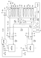
- FIG. 2 is a schematic diagram showing a coal (pulverized coal) drying gas system according to the first embodiment of the present invention.
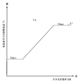
- FIG. 3 is a schematic diagram showing a setting function of the high-temperature exhaust gas temperature (temperature of the high-temperature exhaust gas after temperature adjustment by the high-temperature exhaust gas) in the first embodiment of the present invention.
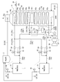
- FIG. 4 is a schematic diagram showing a coal (pulverized coal) drying gas system according to a second embodiment of the present invention.
- FIG. 5 is a schematic diagram showing a coal (pulverized coal) drying gas system according to a third embodiment of the present invention.
- FIG. 6 is a schematic view showing a coal (pulverized coal) drying gas system according to a fourth embodiment of the present invention.
- the overall configuration of the coal gasification power generation facility according to the first embodiment of the present invention will be described with reference to FIG.
- the coal gasification combined cycle power generation facility (carbon-containing solid fuel gasification power generation facility, hereinafter also referred to as “IGCC system”) 100 according to the first embodiment of the present invention shown in FIG. 1 is gasified mainly using air as an oxidant.
- An air combustion method for generating the product gas 21 in the furnace 4 is adopted, and the product gas 24 after purification by the gas purification device 7 is supplied to the gas turbine 8 as a gas turbine fuel.
- the IGCC system 100 shown in FIG. 1 is an air combustion type (air-blown) coal gasification combined power generation facility.
- the IGCC system 100 includes a pulverized coal machine (pulverizer) 1,1, a dust collector 2, a hopper 3, a gasifier 4, a gas cooler 5, a char recovery device 6, A gas purification device 7, a gas turbine 8, an exhaust heat recovery boiler (hereinafter also referred to as “HRSG”) 9, a steam turbine 10, a generator 11, a hopper 12, and an air separation device 13 are configured.
- a part of the exhaust gas supplied from the gas turbine 8 to the HRSG 9 is extracted and supplied to the pulverized coal machine 1 as the drying gas 26 (the drying gas system will be described in detail later).
- coal (carbon-containing solid fuel) 19 that is a raw material of the generated gas 24 is pulverized into fine particles while being heated and dried with a drying gas 26 to produce pulverized coal (pulverized fuel) 20.
- the pulverized coal 20 thus produced is conveyed to the dust collector 2 by the drying gas 26.
- the drying gas 26 and the pulverized coal 20 are separated, and the drying gas 26 is sent to the chimney 95 of the HRSG 9 and mixed with the exhaust gas heat-recovered by the HRSG 9 to form a chimney as an exhaust gas 25e. 95 to the atmosphere.
- the pulverized coal 20 separated from the drying gas 26 falls by gravity and is collected in the hopper 3.
- the pulverized coal 20 collected in the hopper 3 is conveyed into the gasification furnace 4 by nitrogen gas (conveying gas) 52 introduced for pressurized conveyance from the air separation device 13 described later.
- the gasifier 4 is supplied with pulverized coal 20 and a char 22 which will be described later as raw materials for the product gas 24.
- the pulverized coal 20 and the char 22 are generated by gasification using the compressed air 50 supplied from the compressor 8 ⁇ / b> A driven by the gas turbine 8 and the oxygen 53 supplied from the air separator 13 as an oxidant.
- Gas 21 is produced.
- the product gas 21 generated in the gasification furnace 4 is cooled by a gas cooler 5 installed in the gasification furnace 4 and then supplied from the upper part of the gasification furnace 4 to the char recovery device 6.
- the product gas 21 contains char 22, and the char recovery apparatus 6 separates the char 22 from the product gas 21.
- the product gas 23 from which the char 22 has been separated is supplied from the upper part of the char recovery device 6 to the gas purification device 7, purified by the gas purification device 7, and then supplied to the gas turbine 8 as a gaseous product gas 24.
- the char 22 recovered by the char recovery device 6 falls to the hopper 12 due to gravity and is recovered.
- the char 22 in the hopper 12 is returned to the gasification furnace 4 by the nitrogen gas 52 supplied from the air separation device 13, and used as a raw material for the product gas 21 together with the pulverized coal 20.
- the product gas 24 supplied to the gas turbine 8 is supplied to a combustor (not shown) of the gas turbine 8 and burned to generate combustion exhaust gas.
- the combustion exhaust gas is discharged as exhaust gas 25 from the exhaust gas outlet 82 after driving the gas turbine 8. Since the main shaft 81 of the gas turbine 8 driven in this way is connected to the generator 11, the generator 11 can be driven to generate power.
- the exhaust gas 25 discharged from the gas turbine 8 is supplied to the HRSG 9.
- a heat exchanging unit hereinafter, also referred to as “upstream heat exchanging unit” 92 including a plurality of heat exchangers, an in-furnace denitration device 93, and a heat exchanging unit including a plurality of heat exchangers are provided.
- Part hereinafter also referred to as “downstream heat exchanging part”) 94 is provided in this order from the upstream side.
- These heat exchange parts 92 and 94 are connected by a connecting pipe 92b.
- the heat exchange section 94 is supplied with water supply 39 whose flow rate is controlled by opening control of the water supply valve 39a.
- This water supply is heated and becomes steam 40 by exchanging heat with the exhaust gas 25 in the process of circulating through the heat exchanging units 92 and 94.
- the steam 40 is supplied to the steam turbine 10 after the flow rate is controlled by the opening degree control of the steam valve 40a.
- the steam turbine 10 is coaxially connected to the gas turbine 8 and the generator 11, and drives the generator 11 together with the gas turbine 8 to generate power.
- the in-furnace denitration device 93 is a device for reducing NOx (nitrogen oxides) in the exhaust gas 25 in the furnace 91, and detoxifies NOx contained in the exhaust gas 25 by decomposing it with a catalyst using ammonia as a reducing agent. To do.
- the exhaust gas 25 purified by the in-furnace denitration device 93 is discharged from the chimney 95 together with the drying gas 26 to the atmosphere as described above.
- the HRSG 9 includes an upstream heat exchanger 92 located upstream of the in-furnace denitration device 93 and a downstream side located downstream of the in-furnace denitration device 93.
- a heat exchanging portion 94 is provided.
- the upstream heat exchange unit 92 is configured as a heat exchanger group including four heat exchangers 92a
- the downstream heat exchange unit 94 is configured as a heat exchanger group including four heat exchangers 94a. ing.
- upstream heat exchanger group 92 or “heat exchanger group 92”
- downstream heat exchange section 94 is referred to as “downstream heat exchanger group 94” or “heat This is referred to as “exchanger group 94”.
- the upstream heat exchanger 92a is, for example, an evaporator, a reheater, or a superheater.
- the downstream heat exchanger 94a is, for example, a economizer or an evaporator.
- the drying gas 26 is adjusted by mixing exhaust gases 25L, 25H, and 25HH.
- the exhaust gas 25H is extracted from an extraction position (high temperature extraction position) 30H that is set downstream of the heat exchanger group 92 and the in-furnace denitration device 93.
- the extraction position 30 ⁇ / b> H is set on the upstream side of the heat exchanger group 94. Accordingly, the exhaust gas 25H extracted from the extraction position 30H is denitrated by the in-furnace denitration device 93 and is recovered by the heat exchanger group 92 but before being recovered by the heat exchanger group 94. It is a high temperature exhaust gas.
- the exhaust gas 25H is also referred to as “high temperature exhaust gas 25H”.
- the exhaust gas 25L is extracted from an extraction position (low temperature extraction position) 30L positioned downstream from the heat exchanger group 92 and the in-furnace denitration device 93.
- the extraction position 30L is set on the downstream side of the heat exchanger group 94. Therefore, the exhaust gas 25L extracted from the extraction position 30L is a low-temperature exhaust gas after being denitrated by the in-furnace denitration device 93 and heat recovered by the heat exchanger groups 92 and 94.
- the exhaust gas 25L is also referred to as “low temperature exhaust gas 25L”.
- Exhaust gas 25HH is extracted from an extraction position (high temperature extraction position) 30HH that is set upstream of the in-furnace denitration device 93.
- the extraction position 30HH is set on the upstream side of the heat exchanger group 92. Accordingly, the exhaust gas 25HH extracted from the extraction position 30HH is before the denitration treatment by the in-furnace denitration device 93 and before the heat recovery by the heat exchanger groups 92 and 94, and is higher than the high temperature exhaust gas 25H.
- the exhaust gas 25HH is also referred to as “high-temperature exhaust gas 25HH”.
- the in-furnace 91 is connected in communication with a high-temperature exhaust gas duct (high-temperature exhaust gas line) 31H provided outside the furnace at the extraction position 30H.
- This high temperature exhaust gas duct 31H branches into high temperature exhaust gas ducts (high temperature exhaust gas lines) 31Ha, 31Ha, and each high temperature exhaust gas duct 31Ha is connected to the pulverized coal machine 1 respectively.
- pulverized coal is used as a drying gas 26 for the coal 19 (pulverized coal 20). Supplied to the machine 1,1.
- the inside 91 of the furnace is connected to a low temperature exhaust gas duct (low temperature exhaust gas line) 31L provided outside the furnace at the extraction position 30L.
- This low temperature exhaust gas duct 31L branches into low temperature exhaust gas ducts (low temperature exhaust gas lines) 31La, 31La, and each low temperature exhaust gas duct 31La is connected to a high temperature exhaust gas duct 31Ha.
- the low temperature exhaust gas 25L is supplied to the high temperature exhaust gas ducts 31Ha and 31Ha as a temperature adjusting gas for lowering the temperature of the high temperature exhaust gas 25H.
- the furnace interior 91 is connected to a high-temperature exhaust gas duct (high-high exhaust gas line) 31HH provided outside the furnace at the extraction position 30HH.
- the high temperature exhaust gas duct 31HH is connected to the high temperature exhaust gas duct 31H.
- the high-temperature exhaust gas 25HH is supplied to the high-temperature exhaust gas duct 31H as a temperature-regulating gas for raising the temperature of the high-temperature exhaust gas 25H, and the heated high-temperature exhaust gas 25H ′ is adjusted.
- the high temperature exhaust gas duct 31H is provided with a temperature sensor 60 for detecting the temperature of the high temperature exhaust gas 25H ′ on the downstream side of the connecting portion with the high temperature exhaust gas duct 31HH.
- a temperature adjustment damper (temperature adjustment means) 61 is interposed in the high-temperature exhaust gas duct 31HH. The detection signal of the temperature sensor 60 is output to the temperature adjustment damper 61, and the temperature adjustment damper 61 changes the damper opening based on the detection signal of the temperature sensor 60. Thereby, the flow rate of the high-temperature exhaust gas 25HH mixed with the high-temperature exhaust gas 25H is adjusted by the temperature adjustment damper 61 so that the high-temperature exhaust gas 25H ′ is heated to a predetermined set temperature.
- the set temperature adjusted by the temperature control damper 61 is set based on the setting function shown in FIG. 3 according to the load (hereinafter referred to as “gasifier load”) GID of the gasifier 4, for example.
- This setting function is stored in the temperature control damper 61 in advance.
- the set temperature TS of the high temperature exhaust gas 25H ′ is set to a higher temperature as the gasifier negative addition GID increases within the range between the minimum temperature TSmin and the maximum temperature TSmax. This is because the higher the gasifier negative GID is, the more the coal 19 (pulverized coal 20) is consumed, and the amount of heat required for drying the coal 19 (pulverized coal 20) (hereinafter referred to as “necessary drying calorie”).
- the minimum temperature TS_min is such that the moisture contained in the pulverized coal 20 can be dried to a predetermined amount at a partial load, and the exhaust gas flow rates flowing through the ducts 31H, 31Ha, 31HH are used for various control devices (dampers and valves). It is set within the possible range.
- the flow rate of the high-temperature exhaust gas 25H ′ is controlled to be substantially constant regardless of the gasifier negative addition GID by the control of the flow control damper 63 described later. That is, the change in the required amount of drying heat (according to the change in the amount of pulverized coal) due to the change in the gasifier negative addition GID is handled by changing the temperature of the high-temperature exhaust gas 25H ′ (and thus the drying gas 26). .
- the temperature of the high temperature exhaust gas 25H ′ (and thus the drying gas 26) is controlled to be substantially constant regardless of the gasification furnace negative GID, and the flow rate of the high temperature exhaust gas 25H ′ (and thus the drying gas 26) is gasified. It is also possible to change it according to the furnace negative GID. That is, it can be considered that the change in the required amount of drying heat accompanying the change in the gasification furnace negative addition GID can be dealt with by changing the flow rate of the high-temperature exhaust gas 25H ′ (and thus the drying gas 26).
- the flow rate of the drying gas 26 is reduced when the gasification furnace negative GID becomes low in load, but at this time, the flow rate of the low temperature exhaust gas 25L is also reduced, so that the tempering function of the low temperature exhaust gas 25L is not effective. It may be enough. Therefore, with respect to the change in the required amount of drying heat accompanying the change in the gasification furnace negative addition GID, the temperature of the high-temperature exhaust gas 25H ′ is set to the gasification furnace negative addition GID while the flow rate of the drying gas 26 is substantially constant as described above. It is preferable to respond by changing according to the above.
- each pulverized coal machine 1 and the dust collector 2 are connected, and each duct 32 through which the pulverized coal 20 and the drying gas 26 circulate is provided with a temperature sensor 66.
- the detection signals of these temperature sensors 66 are output to the temperature adjustment dampers 65 provided in the respective low temperature exhaust gas ducts 31La, and the temperature adjustment dampers 65 are opened based on the detection signals. Change the degree.
- the temperature of the dry gas 26 high-temperature exhaust gas 25H ′
- the flow rate of the low-temperature exhaust gas 25 ⁇ / b> L is adjusted by the temperature adjustment damper 65.
- each high temperature exhaust gas duct 31Ha is provided with a flow sensor 62 and a flow control damper 63 in this order from the upstream side, and each low temperature exhaust gas duct 31La is provided upstream of the temperature control damper 65, respectively.
- a flow sensor 64 is provided. The detection signal of the flow sensor 62 and the detection signal of the flow sensor 64 are each output to the flow adjustment damper 63, and each flow adjustment damper 63 changes the damper opening degree according to these detection signals.
- the total flow rate of the high temperature exhaust gas 25H ′ flowing through the high temperature exhaust gas duct 31Ha and the low temperature exhaust gas 25L flowing through the low temperature exhaust gas duct 31La is adjusted to each flow condition damper.
- 63 is adjusted to a predetermined flow rate.
- the temperature sensors 60 and 66, the temperature control dampers 61 and 65, the flow rate sensors 62 and 64, and the flow control damper 63 are omitted.
- the drying gas 26 is transported to the dust collector 2 together with the pulverized coal 20, and separated from the pulverized coal 20, and then the duct 33 is passed through. To the chimney 95 of the HRSG 9.
- the NOx concentration is denitrated by the in-furnace denitration device 93 from the extraction position 30H downstream of the in-furnace denitration device 93 and upstream of the downstream heat exchanger group 94.
- the high-temperature exhaust gas (high-temperature exhaust gas) 25H having a low (nitrogen oxide concentration) and before being heat-recovered by the downstream heat exchanger group 94 is extracted (high-temperature exhaust gas extraction step).
- the NOx concentration is reduced by the in-furnace denitration device 93 from the extraction position 30L downstream of the in-furnace denitration device 93 and the downstream heat exchanger group 94, and the heat recovery is performed by the downstream heat exchanger group 94.
- the low-temperature exhaust gas (low-temperature exhaust gas) 25L after it has been extracted is extracted (low-temperature exhaust gas extraction step).
- the exhaust gas having a higher temperature than the exhaust gas 25H ( High-temperature exhaust gas) 25HH is extracted (high-temperature exhaust gas extraction step).
- the flow rate of the high-temperature exhaust gas 25HH supplied to the high-temperature exhaust gas 25H is controlled by the temperature control damper 61, and the high-temperature exhaust gas 25H is temperature-controlled to a predetermined temperature on the high temperature side (the high-temperature exhaust gas 25H having a higher temperature than the high-temperature exhaust gas 25H). ′).
- the flow rate of the low temperature exhaust gas 25L supplied to the high temperature exhaust gas 25H ′ is controlled by the temperature control damper 65, the temperature of the high temperature exhaust gas 25H ′ is adjusted to the low temperature side, and the coal 19 (pulverized coal 20) does not ignite during drying.
- the drying gas 26 is finally adjusted to such a temperature (mixing step). Then, the drying gas 26 is supplied to the pulverized coal machine 1 to dry the coal 19 (pulverized coal 20).
- the denitration efficiency of the in-furnace denitration device 93 becomes maximum at a predetermined temperature (for example, about 350 ° C., hereinafter referred to as the maximum efficiency temperature).
- the HRSG 9 uses the in-furnace denitration device 93 so that the temperature of the exhaust gas 25 flowing into the in-furnace denitration device 93 becomes the maximum efficiency temperature (including the temperature near the maximum efficiency temperature; hereinafter the same) Tef.
- the arrangement and the heat transfer area of the heat exchanger groups 92 and 94 are planned, and operation conditions such as the evaporation amount are set.
- the exhaust gases 25H and 25L having the maximum efficiency temperature Tef or less can be extracted from the extraction positions 30H and 30L on the downstream side of the in-furnace denitration device 93.
- the extraction position 30HH is upstream of the in-furnace denitration device 93 and the heat exchanger groups 92 and 94, the exhaust gas 25HH having a temperature higher than the maximum efficiency temperature Tef can be extracted from the extraction position 30HH.
- the temperature of the exhaust gas 25HH is, for example, about 550 ° C. at the rated load, but differs depending on the operation conditions and the plant. In the case of partial load, the temperature is lower than this temperature, and the temperature of the exhaust gas 25HH is limited to about 550 ° C. It is not something.
- the high temperature exhaust gas 25HH extracted from the upstream side of the in-furnace denitration device 93 is used to dry the gas 26.
- the drying gas 26 can be heated to a higher temperature.
- the drying gas 26 is used for drying the coal 19 (pulverized coal 20), and then mixed with the exhaust gas of the HRSG 9 as described above, and discharged to the atmosphere as the exhaust gas 25e. For this reason, it is necessary to reduce the NOx concentration of the drying gas 26 so that the NOx concentration of the exhaust gas 25e becomes a target value (for example, a regulation value) or less.
- the high temperature exhaust gas 25H denitrated by the in-furnace denitration device 93 is used, and the high temperature exhaust gas 25H is controlled by the in-furnace denitration device 93 as a temperature control exhaust gas for controlling the temperature of the high temperature exhaust gas 25H to the low temperature side. 25 L of low-temperature exhaust gas that has been denitrated is used.
- the drying gas 26 adjusted by these exhaust gases 25H, 25L, and 25HH By suppressing the NOx concentration, the NOx concentration of the exhaust gas 25e can be kept within the target value. That is, in the drying gas 26, most of the exhaust gas after the denitration treatment (the high temperature exhaust gas 25H and the low temperature exhaust gas 25L) occupies a part of the high temperature exhaust gas 25HH that has not been denitrated. However, the NOx concentration of the drying gas 26 can be suppressed and the exhaust gas 25e can be kept within the target value.
- the exhaust gas 25H, 25L, and so on so that the NOx concentration of the drying gas 26 becomes a target value (for example, a regulation value) or less.
- the mixing ratio of 25HH is adjusted.
- FIG. 4 A drying gas system that is a main part of the coal gasification power generation facility according to the second embodiment of the present invention will be described with reference to FIG.
- the overall configuration of the coal gasification power generation facility is the same as that of the first embodiment (see FIG. 1), and the same components as those of the first embodiment are denoted by the same reference numerals and description thereof is omitted.
- a NOx sensor (nitrogen oxide concentration detecting means) 67 is provided in a drying gas discharge duct (drying gas discharge line) 33 between the dust collector 2 and the HRSG 9. It has been.
- the NOx sensor 67 detects the NOx concentration of the drying gas 26 that flows through the duct 33.
- a flow control valve (reducing agent supply amount adjusting means) 70 is interposed in a supply pipe 69 for supplying ammonia (reducing agent) 68 to the in-furnace denitration device 93.
- a detection signal (a signal indicating NOx concentration) of the NOx sensor 67 is output to the flow control valve 70.
- the flow control valve 70 increases the opening degree as the NOx concentration indicated by the detection signal of the NOx sensor 67 increases. Thereby, the amount of ammonia supplied from the supply pipe 69 to the in-furnace denitration device 93 increases as the NOx concentration of the drying gas 26 flowing through the duct 33 increases. Since other configurations are the same as those of the first embodiment, description thereof is omitted.
- the drying gas 26 is used to dry the coal 19 (pulverized coal 20) in the pulverized coal machine 1, and then mixed with the HRSG exhaust gas and discharged to the atmosphere as the exhaust gas 25e. It is desirable to reduce the concentration to as low a concentration as possible. Therefore, in the present embodiment, the amount of ammonia supplied to the in-furnace denitration device 93 is adjusted according to the NOx concentration of the drying gas 26 (reducing agent supply amount adjustment step).
- the denitration performance of the in-furnace denitration device 93 is improved, the NOx concentration of the high temperature exhaust gas 25H and the low temperature exhaust gas 25L is reduced, and the NOx concentration of the drying gas 26 is further reduced to a NOx concentration lower than that of the first embodiment. It becomes possible to reduce.
- the NOx sensor 67 is replaced with the duct 33 in the chimney 95. It may be provided. Further, the NOx concentration in the duct 33 or the chimney 95 can be confirmed in the central control room (not shown) based on the detection signal of the NOx sensor 67, and the operator who has confirmed the NOx concentration can control the flow control in the central control room. You may make it operate the operation part manually and control the opening degree of the flow control valve 70.
- the flow regulating valve operating unit together with the flow regulating valve 70 constitutes the reducing agent supply amount adjusting means of the present invention.
- a drying gas discharge duct (drying gas discharge line) 33 is connected to the in-furnace 91 of the HRSG 9 on the upstream side of the in-furnace denitration device 93. is doing.
- the duct 33 is connected to the in-furnace 91 immediately upstream of the in-furnace denitration device 93 (in other words, between the in-furnace denitration device 93 and the upstream heat exchanger group 92).
- the connection position of the duct 33 is not limited as long as it is upstream of the in-furnace denitration device 93. Therefore, the duct 33 may be connected to the furnace 91 either between the upstream heat exchangers 92 a or upstream of the upstream heat exchanger group 92. Since other configurations are the same as those of the first embodiment, description thereof is omitted.
- the NOx concentration of the drying gas 26 may be increased depending on the operating conditions and the like. Specifically, when the coal 19 contains a large amount of N, the NOx concentration of the high-temperature exhaust gas 25HH extracted from the upstream side of the in-furnace denitration device 93, and hence the NOx concentration of the drying gas 26 containing the high-temperature exhaust gas 25HH. Becomes higher. Moreover, when the coal 19 contains a lot of moisture, or when the gasifier load GID is high and the amount of coal used is large, the amount of heat required to dry the coal 19 also increases.
- the proportion of the high-temperature exhaust gas 25HH (that is, the exhaust gas that has not been denitrated by the in-furnace denitration device 93) in the drying gas 26 increases, The NOx concentration of the gas 26 is increased.
- the drying gas 26 is returned to the upstream side of the in-furnace denitration device 93 via the duct 33 (drying gas recirculation step). Therefore, the drying gas 26 is denitrated by the in-furnace denitration device 93. As a result, the NOx concentration of the exhaust gas 25e including the drying gas 26 and discharged to the atmosphere can be reduced to a target value or less.
- the drying gas 26 returned to the upstream side of the in-furnace denitration device 93 through the duct 33 is at a low temperature because it is after the coal 19 (pulverized coal 20) is dried.
- the temperature of the drying gas 26 is expected to be significantly lower than the maximum efficiency temperature Tef of the in-furnace denitration device 93, the amount of heat exchanged in the upstream heat exchanger group 92 is reduced by reducing the amount of steam in the HRSG 9.
- the exhaust gas temperature at the outlet of the upstream heat exchanger group 92 that is, the inlet of the in-furnace denitration device 93
- Tef the maximum efficiency temperature
- a temperature sensor 33a is provided in the duct 33, and the temperature sensor 33a detects the temperature Tg of the drying gas 26 after drying the coal 19 (pulverized coal 20), and this temperature Tg is the maximum efficiency.
- Tb Tef + ⁇ , ⁇ : marginal temperature, ⁇ > 0
- Tef Tef + ⁇ , ⁇ : marginal temperature, ⁇ > 0
- the water supply valve 39a at the inlet of the HRSG 9 and the steam at the outlet of the HRSG 9 The amount of steam of the HRSG 9 may be reduced by reducing the opening of at least one of the valves 40a.
- the drying gas 26 is returned to the upstream side of the in-furnace denitration device 93, the amount of heat collected from the upstream heat exchanger group 92 in advance so that the exhaust gas temperature at the inlet of the in-furnace denitration device 93 becomes the maximum efficiency temperature Tef.
- You can also respond by planning. Thereby, the denitration performance of the in-furnace denitration apparatus 93 can be maintained in an optimal state.
- the denitration performance of the in-furnace denitration device 93 is suppressed by returning the drying gas 26 to the inside of the furnace 91 upstream of the position shown in FIG.
- the drying gas 26 does not flow into the in-furnace denitration device 93 at a low temperature but mixes with the surrounding high-temperature exhaust gas and After being heated by the high-temperature exhaust gas and heated up, it flows into the in-furnace denitration device 93.
- a high temperature exhaust gas duct 31 ⁇ / b> HH is provided with an out-of-furnace denitration device 71.
- the in-furnace denitration device 71 has higher heat resistance and higher denitration efficiency on the high temperature side than the in-furnace denitration device 93 so that it has heat resistance against the high-temperature exhaust gas 25HH and can perform denitration processing with high efficiency (maximum).
- a high-temperature denitration system is used (efficiency temperature Tef is on the high temperature side). Since other configurations are the same as those of the first embodiment, description thereof is omitted.
- the drying gas 26 is mixed with the exhaust gas of the HRSG 9 and discharged to the atmosphere as the exhaust gas 25e. For this reason, it is necessary to suppress the NOx concentration of the drying gas 26 so that the NOx concentration of the exhaust gas 25e becomes a target value (for example, a regulation value) or less.
- the non-denitration-treated high-temperature exhaust gas 25HH extracted from the upstream side of the in-furnace denitration device 93 is denitrated by the out-of-furnace denitration device 71 (high-temperature exhaust gas denitration step).
- the NOx concentration of the drying gas 26 adjusted using the high-temperature exhaust gas 25HH can be suppressed, and the NOx concentration of the exhaust gas 25e can be made equal to or less than the target value.
- the out-of-furnace denitration apparatus 71 has a smaller amount of processing gas and a smaller capacity than the in-furnace denitration apparatus 93, thereby suppressing an increase in cost. Can do. Therefore, the NOx concentration of the exhaust gas 25e can be reduced below the target value while suppressing an increase in cost.
- the temperature of the high-temperature exhaust gas 25HH is high. Is used.
- the high-temperature exhaust gas 25HH is extracted from between the two heat exchangers 92a on the downstream side of the upstream heat exchanger group 92.
- the high-temperature exhaust gas 25HH has a temperature lower than that of the above embodiment, a denitration device having the same specifications as the in-furnace denitration device 93 (which can treat exhaust gas at the same temperature) is used for the out-of-furnace denitration device 71 It becomes possible. Thereby, the cost increase by providing the in-furnace denitration apparatus 71 can further be suppressed.
- the temperature of the high-temperature exhaust gas 25HH is higher than the maximum efficiency temperature Tef of the out-of-furnace denitration device 71 and the denitration efficiency may be lower than the maximum efficiency, the temperature of the high-temperature exhaust gas 25HH is outside the furnace denitration.
- the temperature does not exceed the heat resistance temperature of the device 71, depending on the NOx concentration of the high-temperature exhaust gas 25HH, it can be operated without any trouble by increasing the amount of ammonia injected into the outside denitration device 71 (released to the atmosphere).
- the NOx concentration of the exhaust gas 25e can be made equal to or less than the target value).
- the extraction position 30HH of the high-temperature exhaust gas 25HH is set on the upstream side of the upstream heat exchanger group 92 in the furnace 91, but the extraction position 30HH of the high-temperature exhaust gas 25HH is It is not limited.
- the extraction position 30HH of the high-temperature exhaust gas 25HH is set between (a) the exhaust gas outlet 82 of the gas turbine 8 and the in-furnace denitration device 93, (b) upstream of the high-temperature extraction position 30H, The position may be set so that at least a part of the upstream heat exchanger group 92 is sandwiched between the extraction position 30H.
- the extraction position 30HH may be provided between the upstream heat exchangers 92a and 92a, and the high-temperature exhaust gas 25HH may be extracted from the extraction position.
- an extraction position 30HH may be provided in the duct 85 between the exhaust gas outlet 82 of the gas turbine 8 and the HRSG 9, and high-temperature exhaust gas may be extracted from the duct 85.
- an extraction position 30HH may be provided in a mutual gap (hereinafter referred to as an internal gap) between the tubes constituting the upstream heat exchanger 92a, and the high-temperature exhaust gas 25HH may be extracted from the internal gap.
- the internal gap is too narrow to provide the extraction position 30HH (to attach the high-temperature and high-temperature exhaust duct 31HH in communication), but a part of the internal clearance is provided so that the extraction position 30HH can be provided. It is possible to provide the extraction position 30HH by intentionally expanding it.
- the extraction position 30H of the high-temperature exhaust gas 25H and the extraction position 30L of the low-temperature exhaust gas 25L are not limited to the positions in the above-described embodiment, but between the downstream heat exchangers 94a and 94a or between the downstream heat exchanger 94a. You may provide in an internal clearance.
- the high temperature exhaust gas 25H is first mixed with the high temperature exhaust gas 25HH, and then the low temperature exhaust gas 25L is mixed.
- the high temperature exhaust gas 25H is first mixed with the low temperature exhaust gas 25L, and then Alternatively, the high-temperature exhaust gas 25HH may be mixed.
- the high temperature exhaust gas 25HH is mixed with the low temperature exhaust gas 25L while controlling the flow rate by the temperature control damper 61, and the exhaust gas obtained by mixing the high temperature exhaust gas 25HH and the low temperature exhaust gas 25L is mixed with the high temperature exhaust gas 25H. May be.
- the high-temperature exhaust gas 25HH is mixed with both the low-temperature exhaust gas 25L and the high-temperature exhaust gas 25H while controlling the flow rate by the temperature control damper 61, and mixed with the high-temperature exhaust gas 25HH and the low-temperature exhaust gas 25L.
- a mixed gas of the high temperature exhaust gas 25HH and the high temperature exhaust gas 25H may be mixed.
- the single generator 11 is driven by the gas turbine 8 and the steam turbine 10, but a generator may be provided for each of the gas turbine 8 and the steam turbine 10. .
- pulverized coal machines 1 are provided, and the pulverized coal supply system of the gasification furnace 4 and the drying gas system incidental thereto are two systems.
- the number of charcoal supply systems and drying gas systems is not limited to this.
- the carbon-containing solid fuel gasification power generation facility of the present invention has been described as an air-blown coal gasification combined power generation facility, but the carbon-containing solid fuel gasification power generation facility of the present invention is It can also be applied to oxygen-blown coal gasification combined power generation facilities.
- the steam generated by the HRSG 9 is supplied to the steam turbine 10 and used for power generation, and a part of the steam generated by the HRSG 9 is used for other uses such as process steam in a factory. You can also Alternatively, the steam generated by the HRSG 9 can be used for other purposes such as factory process steam without being used for power generation. In this case, the steam turbine 10 becomes unnecessary.
- biomass woody biomass such as waste wood and thinned wood can be exemplified, but use other than woody biomass is not excluded.
- Biomass also includes wood pellets processed into pellets. In short, biomass is not limited by the form of processing.
- the low-temperature exhaust gas duct 31L is connected to the high-temperature exhaust gas duct 31Ha
- the high-temperature exhaust gas duct 31Ha and the low-temperature exhaust gas duct 31L may be directly connected to the pulverized coal machine 1, respectively. good.
- the low temperature exhaust gas duct is brought into contact with the coal 19 and the pulverized coal 20 in the pulverized coal machine 1. It is preferable that the connection positions of 31L and the high-temperature exhaust gas duct 31Ha to the pulverized coal machine 1 are close to each other.
Landscapes
- Engineering & Computer Science (AREA)
- Chemical & Material Sciences (AREA)
- Combustion & Propulsion (AREA)
- Mechanical Engineering (AREA)
- General Engineering & Computer Science (AREA)
- Oil, Petroleum & Natural Gas (AREA)
- Organic Chemistry (AREA)
- Thermal Sciences (AREA)
- Physics & Mathematics (AREA)
- Health & Medical Sciences (AREA)
- Biomedical Technology (AREA)
- Environmental & Geological Engineering (AREA)
- Analytical Chemistry (AREA)
- General Chemical & Material Sciences (AREA)
- Chemical Kinetics & Catalysis (AREA)
- Engine Equipment That Uses Special Cycles (AREA)
- Chimneys And Flues (AREA)
- Drying Of Solid Materials (AREA)
Abstract
使用できる炭素含有固体燃料の種類の範囲を拡大できるようにした、炭素含有固体燃料ガス化発電設備及びその炭素含有固体燃料の乾燥用ガスの調整方法を提供する。 高温抽気位置(30H)において炉内(91)から高温排ガス(25H)を抽気する。高温抽気位置(30H)の下流側且つ高温抽気位置(30H)との間に少なくとも熱交換部(94)の一部を挟む低温抽気位置(30L)において、炉内(91)から低温排ガス(25L)を抽気する。さらに、ガスタービン(8)と脱硝装置(93)との間且つ高温抽気位置(30H)との間に少なくとも熱交換部(92)の一部を挟む高高温抽気位置(30HH)において、炉内(91)から、高高温排ガス(25HH)を抽気する。これらの排ガス(25H,25HH,25L)を混合する際、高温排ガス(25H)及び低温排ガス(25L)の少なくとも一方の排ガスのガス温度が所定温度となるように、前記の少なくとも一方の排ガスに供給する高高温排ガス(25HH)の流量を調整する。
Description
本発明は、排熱回収ボイラから排ガスを抽気し、この抽気した排ガスを乾燥用ガスとして炭素含有固体燃料を乾燥する炭素含有固体燃料ガス化発電設備及びその炭素含有固体燃料の乾燥用ガスの調整方法に関する。
従来、高効率の発電設備として石炭ガス化複合発電設備(以下、「IGCCシステム」と呼ぶ。IGCC:Integrated Coal Gasification Combined Cycle)が知られている。
IGCCシステムでは、石炭をガス化して生成した生成ガスを燃料としてガスタービンを運転して発電を行い、併せて、ガスタービンの排熱を使用して生成した蒸気を用いて蒸気タービンを駆動させて発電を行う。具体的には、微粉炭機により石炭を乾燥・粉砕して微粉炭を製造し、この微粉炭をガス化炉に供給してガス化する。そして、ガス化により生成された生成ガスを燃料としてガスタービンを運転し、このガスタービンにより、ガスタービンに連結された発電機を駆動して発電する。加えて、ガスタービンから排出される排ガスを排熱回収ボイラに導入して蒸気を生成し、この蒸気で蒸気タービンひいては蒸気タービンに連結された発電機を駆動して発電を行う。
IGCCシステムでは、石炭をガス化して生成した生成ガスを燃料としてガスタービンを運転して発電を行い、併せて、ガスタービンの排熱を使用して生成した蒸気を用いて蒸気タービンを駆動させて発電を行う。具体的には、微粉炭機により石炭を乾燥・粉砕して微粉炭を製造し、この微粉炭をガス化炉に供給してガス化する。そして、ガス化により生成された生成ガスを燃料としてガスタービンを運転し、このガスタービンにより、ガスタービンに連結された発電機を駆動して発電する。加えて、ガスタービンから排出される排ガスを排熱回収ボイラに導入して蒸気を生成し、この蒸気で蒸気タービンひいては蒸気タービンに連結された発電機を駆動して発電を行う。
IGCCシステムでは、ガスタービンの排ガスの一部を取り出して微粉炭機へ供給し、この排ガスを石炭乾燥用のガス(以下、「乾燥用ガス」と呼ぶ)として使用することにより、サイクル内の熱を有効利用して発電化効率を高めている。
このようなガスタービンの排ガスを乾燥用ガスとして使用する技術として、例えば特許文献1に開示された技術がある。以下、特許文献1に開示された技術を説明するが、その説明では、参考に、特許文献1で使用されている符号を括弧付きで示す。
このようなガスタービンの排ガスを乾燥用ガスとして使用する技術として、例えば特許文献1に開示された技術がある。以下、特許文献1に開示された技術を説明するが、その説明では、参考に、特許文献1で使用されている符号を括弧付きで示す。
特許文献1(第2頁第4欄第5~13行及び図1など参照)には、「排ガスボイラ(29)の上流側及び下流側からそれぞれ燃焼排ガスの一部を取り出して混合し、この混合した燃焼排ガスを、微粉炭乾燥用熱源として微粉炭機(12)へ供給するようにした技術」が開示されている。
従来の一般的なIGCCシステムでは、排熱回収ボイラ内に脱硝装置(炉内脱硝装置)が配置されており、排熱回収ボイラ内の脱硝装置の出口の排ガスと、排熱回収ボイラの出口の排ガスとをそれぞれ一部抽気し、これらの抽気した排気を混合して、石炭の乾燥用ガスとして微粉炭機へ供給し、微粉炭機から排出される乾燥用ガスを大気へ排出している。
このような構成により、脱硝装置の出口の比較的高温の排ガスと、排熱回収ボイラの出口の比較的低温の排ガスとを混合することで、乾燥用ガスを所望の温度に調整すると共に、脱硝装置の出口の排ガスと排熱回収ボイラの出口の排ガスとが共に脱硝装置により処理されて、大気へ放出する乾燥用ガスのNOx濃度を規制値以下としている。
このような構成により、脱硝装置の出口の比較的高温の排ガスと、排熱回収ボイラの出口の比較的低温の排ガスとを混合することで、乾燥用ガスを所望の温度に調整すると共に、脱硝装置の出口の排ガスと排熱回収ボイラの出口の排ガスとが共に脱硝装置により処理されて、大気へ放出する乾燥用ガスのNOx濃度を規制値以下としている。
ところで、脱硝装置の脱硝効率は、作動温度が所定温度(例えば350℃程度)のときに最高となり(以下、この所定温度を「最大効率温度」と呼ぶ)、排熱回収ボイラは、脱硝装置の作動温度が最大効率温度(又は最大効率温度付近)となるように運用される。このため、上記技術では、脱硝装置の出口及び排ガスボイラの出口の各排ガスの温度、ひいてはこれらが混合されてなる乾燥用ガスの温度には、脱硝装置の最大効率温度にしたがって上限が設けられることとなる。
石炭(微粉炭)の乾燥が不十分であると、石炭を搬送する配管内で結露・凝集が発生するなどして石炭の搬送特性を悪化させる可能性があり、また、ガス化炉において入力された熱量が水分の蒸発に使用されてガス化効率を低下させてしまう。石炭が水分を多く含むほど、乾燥を十分に行うために多くの熱量を必要とするが、従来の一般的なIGCCシステムでは、上述のように乾燥用ガスの温度に、脱硝装置の最大効率温度に応じた上限があるため、高水分炭では乾燥が不十分となる可能性がある。このため、使用できる炭種が制限されてしまうという課題がある。
このような課題は、石炭ガス化複合発電設備に限らず、水分を多く含む炭素含有固体燃料(例えばバイオマス)をガス化して発電を行う炭素含有固体燃料ガス化発電設備に共通した課題である。
このような課題は、石炭ガス化複合発電設備に限らず、水分を多く含む炭素含有固体燃料(例えばバイオマス)をガス化して発電を行う炭素含有固体燃料ガス化発電設備に共通した課題である。
本発明は、上記のような課題に鑑み創案されたもので、燃料として使用できる炭素含有固体燃料の種類の範囲を拡大できるようにした、炭素含有固体燃料ガス化発電設備及びその炭素含有固体燃料の乾燥用ガスの調整方法を提供することを目的とする。
(1)上記の目的を達成するために、本発明の炭素含有固体燃料ガス化発電設備は、炭素含有固体燃料を粉砕して粉砕燃料とする粉砕装置と、前記粉砕燃料をガス化して生成ガスを生成するガス化炉と、前記生成ガスを燃焼させた燃焼ガスにより駆動されるガスタービンと、前記ガスタービンと連結されて前記ガスタービンにより駆動される発電機と、前記ガスタービンから排出される排ガスを導入し、1以上の熱交換器からなる上流側熱交換部と、炉内脱硝装置と、1以上の熱交換器からなる下流側熱交換部とが、排ガス上流側からこの順に炉内に設けられ、前記上流側熱交換部及び前記下流側熱交換部において前記排ガスから熱回収することにより蒸気を生成する排熱回収ボイラと、前記炉内脱硝装置よりも排ガス下流側に位置設定された高温抽気位置において、前記炉内から高温排ガスを抽気して、前記炭素含有固体燃料の乾燥用ガスとして前記粉砕装置に供給する高温排ガスラインと、前記高温抽気位置よりも前記排ガス下流側に位置設定され、且つ、前記高温抽気位置との間に前記下流側熱交換部の少なくとも一部を挟むように位置設定された低温抽気位置において、前記炉内から低温排ガスを抽気して、前記高温排ガスライン又は前記粉砕装置に供給可能な低温排ガスラインと、前記ガスタービンの排ガス出口と前記炉内脱硝装置との間で、前記高温抽気位置よりも排ガス上流側に位置設定され、且つ、前記高温抽気位置との間に前記上流側熱交換部の少なくとも一部を挟むように位置設定された高高温抽気位置において、前記炉内から高高温排ガスを抽気して、前記高温排ガスライン及び前記低温排ガスラインの少なくとも一方の排ガスラインに供給可能な高高温排ガスラインと、前記高高温排ガスラインに介装され、前記の少なくとも一方の排ガスラインのガス温度が所定温度となるように前記の少なくとも一方の排ガスラインに供給する前記高高温排ガスの流量を調整する温度調整手段とを備えることを特徴としている。
(2)前記炭素含有固体燃料の乾燥に使用された前記乾燥用ガスを、前記粉砕装置から排出する乾燥用ガス排出ラインと、前記乾燥用ガス排出ラインにおける前記乾燥用ガスの窒素酸化物濃度を検出する窒素酸化物濃度検出手段と、前記窒素酸化物濃度検出手段の検出信号に応じて、前記炉内脱硝装置に供給する還元剤の供給量を調整する還元剤供給量調整手段とを備えることが好ましい。
(3)前記炭素含有固体燃料の乾燥に使用された前記乾燥用ガスを、前記粉砕装置から排出する乾燥用ガス排出ラインを備え、前記乾燥用ガス排出ラインを、前記炉内脱硝装置よりも前記排ガス上流側において前記炉内に連通状態に接続することが好ましい。
(4)前記乾燥用ガス排出ラインに温度検出手段を備え、前記温度検出手段により検出された前記乾燥用ガスの温度が、前記炉内脱硝装置の最大効率温度に基づいて設定された基準温度よりも低い場合には、前記排熱回収ボイラへの給水量を制御する給水弁及び前記排熱回収ボイラからの蒸気量を制御する蒸気弁の少なくとも一方の開度を小さくすることが好ましい。
(5)前記高高温排ガスラインに炉外脱硝装置を備えることが好ましい。
(6)上記の目的を達成するために、本発明の炭素含有固体燃料の乾燥用ガスの調整方法は、炭素含有固体燃料をガス化して生成ガスを生成するガス化炉と、前記生成ガスを燃焼させた燃焼用ガスにより駆動されるガスタービンと、前記ガスタービンと連結されて前記ガスタービンにより駆動される発電機と、前記ガスタービンから排出される排ガスから熱回収することにより蒸気を生成する排熱回収ボイラとを備えた炭素含有固体燃料ガス化発電設備において、前記炭素含有固体燃料を乾燥するのに使用される乾燥用ガスの調整方法であって、前記排熱回収ボイラは、1以上の熱交換器からなる上流側熱交換部と、炉内脱硝装置と、1以上の熱交換器からなる下流側熱交換部とが、前記排ガスの流通方向で上流側からこの順に炉内に設けられ、前記炉内脱硝装置よりも前記流通方向で下流側に位置設定された高温抽気位置において、前記炉内から高温排ガスを抽気する、高温排ガス抽気ステップと、前記炉内脱硝装置及び前記高温抽気位置よりも前記流通方向で下流側に位置設定され、且つ、前記高温抽気位置との間に前記下流側熱交換部の少なくとも一部を挟むように位置設定された低温抽気位置において、前記炉内から低温排ガスを抽気する、低温排ガス抽気ステップと、前記ガスタービンの前記排ガスの出口と前記炉内脱硝装置との間で、前記高温抽気位置よりも排ガス上流側に位置設定され、且つ、前記高温抽気位置との間に前記上流側熱交換部の少なくとも一部を挟むように位置設定された高高温抽気位置において、前記炉内から高高温排ガスを抽気する、高高温排ガス抽気ステップと、前記高温排ガスに、前記低温排ガスと、前記高高温排ガスとを混合する混合ステップとを備え、前記混合ステップにおいて、前記高温排ガス及び前記低温排ガスの少なくとも一方の排ガスのガス温度が所定温度となるように、前記の少なくとも一方の排ガスに供給する前記高高温排ガスの流量を調整することを特徴としている。
(7)前記炭素含有固体燃料の乾燥に使用された前記乾燥用ガスの窒素酸化物濃度に応じて、前記炉内脱硝装置に供給する還元剤の供給量を調整する還元剤供給量調整ステップを備えることが好ましい。
(8)前記炭素含有固体燃料の乾燥に使用された前記乾燥用ガスを、前記炉内脱硝装置よりも前記排ガス上流側において前記炉内に戻す、乾燥用ガス再循環ステップを備えることが好ましい。
(9)前記炭素含有固体燃料の乾燥に使用された前記乾燥用ガスの温度が、前記炉内脱硝装置の最大効率温度に基づいて設定された基準温度よりも低い場合には、前記排熱回収ボイラの給水量及び前記排熱回収ボイラの蒸気量の少なくとも何れか一方を絞ることが好ましい。
(10)前記高高温排ガスを脱硝処理する、高高温排ガス脱硝ステップを備えることが好ましい。
本発明によれば、それぞれ炉内脱硝装置よりも排ガス下流側から抽気した低温排ガス及び高温排ガスに加えて、炉内脱硝装置よりも上流側から抽気した高高温排ガスを使用して、粉砕装置において炭素含有固体燃料を乾燥させるための乾燥用ガスの温度を調整することで、乾燥用ガスを高温化することができる。これにより、水分が多めの炭素含有固体燃料を十分に乾燥することができ、炭素含有固体燃料ガス化発電設備の燃料として使用できる炭素含有固体燃料の種類の範囲を拡大することができる。
以下、図面を参照して、本発明の実施の形態について説明する。
本実施形態では、本発明の炭素含有固体燃料ガス化発電設備を石炭ガス化複合発電設備に適用した例を説明する。
なお、以下に示す実施形態はあくまでも例示に過ぎず、以下の実施形態で明示しない種々の変形や技術の適用を排除する意図はない。以下の実施形態の各構成は、それらの趣旨を逸脱しない範囲で種々変形して実施することができるとともに、必要に応じて取捨選択することができ、あるいは適宜組み合わせることが可能である。
また、以下の説明における「上流」及び「下流」とは、特段の説明を行わない限り、ガスタービンの排ガスの流通方向における上流,下流を意味するものとする。
本実施形態では、本発明の炭素含有固体燃料ガス化発電設備を石炭ガス化複合発電設備に適用した例を説明する。
なお、以下に示す実施形態はあくまでも例示に過ぎず、以下の実施形態で明示しない種々の変形や技術の適用を排除する意図はない。以下の実施形態の各構成は、それらの趣旨を逸脱しない範囲で種々変形して実施することができるとともに、必要に応じて取捨選択することができ、あるいは適宜組み合わせることが可能である。
また、以下の説明における「上流」及び「下流」とは、特段の説明を行わない限り、ガスタービンの排ガスの流通方向における上流,下流を意味するものとする。
[1.第1実施形態]
[1-1.石炭ガス化発電設備の全体構成]
[1-1.石炭ガス化発電設備の全体構成]
本発明の第1実施形態に係る石炭ガス化発電設備の全体構成を、図1を参照して説明する。
図1に示す本発明の第1実施形態に係る石炭ガス化複合発電設備(炭素含有固体燃料ガス化発電設備、以下、「IGCCシステム」とも呼ぶ)100は、主に空気を酸化剤としてガス化炉4で生成ガス21を生成する空気燃焼方式を採用し、ガス精製装置7で精製した後の生成ガス24をガスタービン燃料としてガスタービン8へ供給している。すなわち、図1に示すIGCCシステム100は、空気燃焼方式(空気吹き)の石炭ガス化複合発電設備である。
図1に示す本発明の第1実施形態に係る石炭ガス化複合発電設備(炭素含有固体燃料ガス化発電設備、以下、「IGCCシステム」とも呼ぶ)100は、主に空気を酸化剤としてガス化炉4で生成ガス21を生成する空気燃焼方式を採用し、ガス精製装置7で精製した後の生成ガス24をガスタービン燃料としてガスタービン8へ供給している。すなわち、図1に示すIGCCシステム100は、空気燃焼方式(空気吹き)の石炭ガス化複合発電設備である。
具体的に説明すると、IGCCシステム100は、図1に示すように、微粉炭機(粉砕装置)1,1,集塵機2,ホッパ3,ガス化炉4,ガス冷却器5,チャー回収装置6,ガス精製装置7,ガスタービン8,排熱回収ボイラ(以下「HRSG」とも呼ぶ)9,蒸気タービン10,発電機11,ホッパ12及び空気分離装置13を備えて構成される。
このIGCCシステム100では、ガスタービン8からHRSG9に供給された排ガスの一部を抽出して乾燥用ガス26として微粉炭機1に供給する(乾燥用ガス系統については詳しく後述する)。微粉炭機1では、生成ガス24の原料となる石炭(炭素含有固体燃料)19を、乾燥用ガス26により加熱乾燥しながら、細かい粒子状に粉砕して微粉炭(粉砕燃料)20を製造する。
こうして製造された微粉炭20は、乾燥用ガス26により集塵機2へ搬送される。集塵機2の内部では、乾燥用ガス26と微粉炭20とが分離され、乾燥用ガス26は、HRSG9の煙突95へと送られて、HRSG9で熱回収された排ガスと混合して排ガス25eとして煙突95から大気へと排出される。一方、乾燥用ガス26から分離された微粉炭20は、重力により落下してホッパ3に回収される。
こうして製造された微粉炭20は、乾燥用ガス26により集塵機2へ搬送される。集塵機2の内部では、乾燥用ガス26と微粉炭20とが分離され、乾燥用ガス26は、HRSG9の煙突95へと送られて、HRSG9で熱回収された排ガスと混合して排ガス25eとして煙突95から大気へと排出される。一方、乾燥用ガス26から分離された微粉炭20は、重力により落下してホッパ3に回収される。
ホッパ3内に回収された微粉炭20は、後述する空気分離装置13から加圧搬送用として導入された窒素ガス(搬送用ガス)52により、ガス化炉4内へ搬送される。
ガス化炉4には、生成ガス24の原料として微粉炭20及び後述するチャー22が供給される。ガス化炉4では、ガスタービン8により駆動される圧縮機8Aから供給される圧縮空気50及び空気分離装置13から供給される酸素53を酸化剤として、微粉炭20及びチャー22をガス化して生成ガス21が製造される。
ガス化炉4で生成された生成ガス21は、ガス化炉4内に設置されたガス冷却器5により冷却された後に、ガス化炉4の上部からチャー回収装置6へ供給される。
ガス化炉4には、生成ガス24の原料として微粉炭20及び後述するチャー22が供給される。ガス化炉4では、ガスタービン8により駆動される圧縮機8Aから供給される圧縮空気50及び空気分離装置13から供給される酸素53を酸化剤として、微粉炭20及びチャー22をガス化して生成ガス21が製造される。
ガス化炉4で生成された生成ガス21は、ガス化炉4内に設置されたガス冷却器5により冷却された後に、ガス化炉4の上部からチャー回収装置6へ供給される。
生成ガス21はチャー22を含有し、チャー回収装置6では、生成ガス21からチャー22が分離される。チャー22が分離された生成ガス23は、チャー回収装置6の上部からガス精製装置7に供給され、このガス精製装置7によって精製された後、ガス状の生成ガス24としてガスタービン8へ供給される。一方、チャー回収装置6で回収されたチャー22は、重力によりホッパ12に落下して回収される。ホッパ12内のチャー22は、空気分離装置13から供給される窒素ガス52によってガス化炉4へ戻され、微粉炭20とともに生成ガス21の原料として使用される。
ガスタービン8へ供給された生成ガス24は、ガスタービン8の燃焼器(図示略)に供給されて燃焼し、燃焼排ガスを生成する。この燃焼排ガスは、ガスタービン8を駆動した後、その排ガス出口82から排ガス25として排出される。こうして駆動されたガスタービン8は、その主軸81が発電機11と連結されているので、発電機11を駆動して発電を行うことができる。
ガスタービン8から排出された排ガス25は、HRSG9に供給される。HRSG9の炉内91には、複数の熱交換器からなる熱交換部(以下、「上流側熱交換部」とも呼ぶ)92と、炉内脱硝装置93と、複数の熱交換器からなる熱交換部(以下、「下流側熱交換部」とも呼ぶ)94とが、上流側からこの順に設けられている。これらの熱交換部92,94は連絡管92bにより連結されている。
熱交換部94には、給水弁39aの開度制御によって流量を制御された給水39が供給される。この給水は、熱交換部92,94を流通する過程で、排ガス25と熱交換し加熱され蒸気40となる。この蒸気40は、蒸気弁40aの開度制御によって流量を制御された後、蒸気タービン10に供給される。蒸気タービン10は、ガスタービン8及び発電機11と同軸で連結されており、ガスタービン8と共に発電機11を駆動して発電を行わせる。
熱交換部94には、給水弁39aの開度制御によって流量を制御された給水39が供給される。この給水は、熱交換部92,94を流通する過程で、排ガス25と熱交換し加熱され蒸気40となる。この蒸気40は、蒸気弁40aの開度制御によって流量を制御された後、蒸気タービン10に供給される。蒸気タービン10は、ガスタービン8及び発電機11と同軸で連結されており、ガスタービン8と共に発電機11を駆動して発電を行わせる。
炉内脱硝装置93は、炉内91において排ガス25中のNOx(窒素酸化物)を低減するための装置であり、排ガス25に含まれるNOxを、アンモニアを還元剤として触媒により分解して無害化する。炉内脱硝装置93により浄化された排ガス25は、上述したように乾燥用ガス26と共に煙突95から大気へ排出される。
[1-2.乾燥用ガス系統(要部構成)]
本発明の要部である乾燥用ガス系統について、図2を参照してHRSG9の構成と共に説明する。
HRSG9には、図2に示すように、炉内91に、炉内脱硝装置93よりも上流側に位置する上流側熱交換部92と、炉内脱硝装置93よりも下流側に位置する下流側熱交換部94とが備えられている。本実施形態では、上流側熱交換部92は4つの熱交換器92aからなる熱交換器群として構成され、下流側熱交換部94は4つの熱交換器94aからなる熱交換器群として構成されている。以下、上流側熱交換部92を、「上流側熱交換器群92」又は「熱交換器群92」と呼び、下流側熱交換部94を、「下流側熱交換器群94」又は「熱交換器群94」と呼ぶ。
上流側の熱交換器92aは例えば蒸発器や再熱器や過熱器である。下流側熱交換器94aは例えば節炭器(エコノマイザ)や蒸発器である。
本発明の要部である乾燥用ガス系統について、図2を参照してHRSG9の構成と共に説明する。
HRSG9には、図2に示すように、炉内91に、炉内脱硝装置93よりも上流側に位置する上流側熱交換部92と、炉内脱硝装置93よりも下流側に位置する下流側熱交換部94とが備えられている。本実施形態では、上流側熱交換部92は4つの熱交換器92aからなる熱交換器群として構成され、下流側熱交換部94は4つの熱交換器94aからなる熱交換器群として構成されている。以下、上流側熱交換部92を、「上流側熱交換器群92」又は「熱交換器群92」と呼び、下流側熱交換部94を、「下流側熱交換器群94」又は「熱交換器群94」と呼ぶ。
上流側の熱交換器92aは例えば蒸発器や再熱器や過熱器である。下流側熱交換器94aは例えば節炭器(エコノマイザ)や蒸発器である。
上述のように、HRSG9の炉内91に供給された排ガス25の一部を抽出して石炭の乾燥用ガス26として使用する。そして、この乾燥用ガス26は、排ガス25L,25H,25HHを混合して調整される。
排ガス25Hは、熱交換器群92や炉内脱硝装置93よりも下流側に位置設定された抽気位置(高温抽気位置)30Hから抽気される。この抽気位置30Hは、本実施形態では、熱交換器群94よりも上流側に位置設定されている。したがって、抽気位置30Hから抽気される排ガス25Hは、炉内脱硝装置93により脱硝処理され、且つ、熱交換器群92により熱回収された後ではあるが熱交換器群94により熱回収される前の高温の排ガスである。以下、排ガス25Hを「高温排ガス25H」とも呼ぶ。
排ガス25Lは、熱交換器群92や炉内脱硝装置93よりも下流側に位置設定された抽気位置(低温抽気位置)30Lから抽気される。この抽気位置30Lは、本実施形態では、熱交換器群94よりも下流側に位置設定されている。したがって、抽気位置30Lから抽気される排ガス25Lは、炉内脱硝装置93により脱硝処理され、且つ、熱交換器群92,94により熱回収された後の低温の排ガスである。以下、排ガス25Lを「低温排ガス25L」とも呼ぶ。
排ガス25HHは、炉内脱硝装置93よりも上流側に位置設定された抽気位置(高高温抽気位置)30HHから抽気される。この抽気位置30HHは、本実施形態では、熱交換器群92よりも上流側に位置設定されている。したがって、抽気位置30HHから抽気される排ガス25HHは、炉内脱硝装置93により脱硝処理される前、且つ、熱交換器群92,94により熱回収される前であって高温排ガス25Hよりもさらに高温の排ガスである。以下、排ガス25HHを「高高温排ガス25HH」とも呼ぶ。
炉内91は、抽気位置30Hにおいて、炉外に設けられた高温排ガスダクト(高温排ガスライン)31Hと連通状態に接続されている。この高温排ガスダクト31Hは高温排ガスダクト(高温排ガスライン)31Ha,31Haに分岐し、各高温排ガスダクト31Haはそれぞれ微粉炭機1に接続する。これにより、高温排ガス25Hが、後述するように高高温排ガス25HH及び低温排ガス25Lを混入されることによって所定温度に調温された後、石炭19(微粉炭20)の乾燥用ガス26として微粉炭機1,1に供給される。
また、炉内91は、抽気位置30Lにおいて、炉外に設けられた低温排ガスダクト(低温排ガスライン)31Lと連通状態に接続されている。この低温排ガスダクト31Lは低温排ガスダクト(低温排ガスライン)31La,31Laに分岐し、各低温排ガスダクト31Laはそれぞれ高温排ガスダクト31Haに接続する。これにより、低温排ガス25Lが、高温排ガス25Hの降温用の調温用ガスとして高温排ガスダクト31Ha,31Haに供給される。
また、炉内91は、抽気位置30HHにおいて、炉外に設けられた高高温排ガスダクト(高高排ガスライン)31HHと連通状態に接続されている。この高高温排ガスダクト31HHは高温排ガスダクト31Hに接続する。これにより、高高温排ガス25HHが、高温排ガス25Hの昇温用の調温用ガスとして高温排ガスダクト31Hに供給され、昇温された高温排ガス25H′が調整される。
また、炉内91は、抽気位置30HHにおいて、炉外に設けられた高高温排ガスダクト(高高排ガスライン)31HHと連通状態に接続されている。この高高温排ガスダクト31HHは高温排ガスダクト31Hに接続する。これにより、高高温排ガス25HHが、高温排ガス25Hの昇温用の調温用ガスとして高温排ガスダクト31Hに供給され、昇温された高温排ガス25H′が調整される。
また、高温排ガスダクト31Hには、高高温排ガスダクト31HHとの接続部よりも下流側において、高温排ガス25H′の温度を検出する温度センサ60が設けられている。
また、高高温排ガスダクト31HHには温調ダンパ(温度調整手段)61が介装されている。温度センサ60の検出信号は温調ダンパ61に出力されるようになっており、温調ダンパ61は、温度センサ60の検出信号に基づいてダンパ開度を変更する。これにより、高温排ガス25H′が、所定の設定温度まで昇温されるように、高温排ガス25Hに混合される高高温排ガス25HHの流量が温調ダンパ61によって調整される。
また、高高温排ガスダクト31HHには温調ダンパ(温度調整手段)61が介装されている。温度センサ60の検出信号は温調ダンパ61に出力されるようになっており、温調ダンパ61は、温度センサ60の検出信号に基づいてダンパ開度を変更する。これにより、高温排ガス25H′が、所定の設定温度まで昇温されるように、高温排ガス25Hに混合される高高温排ガス25HHの流量が温調ダンパ61によって調整される。
温調ダンパ61で調整する設定温度は、例えば、ガス化炉4の負荷(以下、「ガス化炉負荷」と呼ぶ)GIDに応じて、図3に示す設定関数に基づいて設定される。この設定関数は、温調ダンパ61に予め記憶されている。
図3に示すように、高温排ガス25H′の設定温度TSは、最低温度TSminと最高温度TSmaxとの範囲内において、ガス化炉負加GIDが大きくなるにしたがって高温に設定される。これは、ガス化炉負加GIDが高くなるほど石炭19(微粉炭20)の消費量が多くなり、石炭19(微粉炭20)の乾燥に必要な熱量(以下、「必要乾燥熱量」と呼ぶ)が多くなるためである。最高温度TSmaxは、高温排ガス25H′の温度が、高温排ガス系統の設計温度Td(高温排ガスダクト31H,31Haの設計温度や、高温排ガスダクト31H,31Haに設置される温度センサ60や流量センサ62や流調ダンパ63などの付帯設備の設計温度)を越えないように、前記の設計温度Tdよりも余裕分ΔTだけ低めに設定されている(TSmax=Td-ΔT)。
また、最低温度TS_minは、部分負荷において、微粉炭20が含む水分を所定量に乾燥できるように、且つ、各ダクト31H,31Ha,31HHを流れる排ガス流量が各種制御装置(ダンパや弁)の運用可能範囲に入る範囲で、設定される。
図3に示すように、高温排ガス25H′の設定温度TSは、最低温度TSminと最高温度TSmaxとの範囲内において、ガス化炉負加GIDが大きくなるにしたがって高温に設定される。これは、ガス化炉負加GIDが高くなるほど石炭19(微粉炭20)の消費量が多くなり、石炭19(微粉炭20)の乾燥に必要な熱量(以下、「必要乾燥熱量」と呼ぶ)が多くなるためである。最高温度TSmaxは、高温排ガス25H′の温度が、高温排ガス系統の設計温度Td(高温排ガスダクト31H,31Haの設計温度や、高温排ガスダクト31H,31Haに設置される温度センサ60や流量センサ62や流調ダンパ63などの付帯設備の設計温度)を越えないように、前記の設計温度Tdよりも余裕分ΔTだけ低めに設定されている(TSmax=Td-ΔT)。
また、最低温度TS_minは、部分負荷において、微粉炭20が含む水分を所定量に乾燥できるように、且つ、各ダクト31H,31Ha,31HHを流れる排ガス流量が各種制御装置(ダンパや弁)の運用可能範囲に入る範囲で、設定される。
なお、高温排ガス25H′の流量は、後述の流調ダンパ63の制御によりガス化炉負加GIDに拘わらず概ね一定に制御される。すなわち、ガス化炉負加GIDの変化に伴う(微粉炭量の変化に伴う)必要乾燥熱量の変化を、高温排ガス25H′(ひいては乾燥用ガス26)の温度を変化させることで対応している。
これに対し、ガス化炉負加GIDに拘わらず高温排ガス25H′(ひいては乾燥用ガス26)の温度を概ね一定に制御して、高温排ガス25H′(ひいては乾燥用ガス26)の流量をガス化炉負加GIDに応じて変更することも考えられる。すなわち、ガス化炉負加GIDの変化に伴う必要乾燥熱量の変化を、高温排ガス25H′(ひいては乾燥用ガス26)の流量を変化させることで対応することも考えられる。この場合、ガス化炉負加GIDが低負荷になると乾燥用ガス26の流量を減少させることとなるが、この際には低温排ガス25Lの流量も減少するので、低温排ガス25Lのテンパリング機能が不十分になる可能性もある。したがって、ガス化炉負加GIDの変化に伴う必要乾燥熱量の変化に対しては、上記のように乾燥用ガス26の流量を概ね一定にしつつ高温排ガス25H′の温度をガス化炉負加GIDに応じて変化させることで対応するのが好ましい。
また、各微粉炭機1と集塵機2とを接続し、微粉炭20と乾燥用ガス26とが流通する各ダクト32には、それぞれ温度センサ66が設けられている。これらの温度センサ66の検出信号は、それぞれ、各低温排ガスダクト31Laに設けられた温調ダンパ65に出力されるようになっており、各温調ダンパ65は、この検出信号に基づいてダンパ開度を変更する。これにより、乾燥ガス26(高温排ガス25H′)の温度が、微粉炭20の乾燥に支障のない範囲で微粉炭20の発火のおそれがない温度まで低下するよう、高温排ガス25H′に混合される低温排ガス25Lの流量が温調ダンパ65によって調整される。
さらに、各高温排ガスダクト31Haには、それぞれ、流量センサ62と流調ダンパ63とが上流側からこの順に設けられ、各低温排ガスダクト31Laには、それぞれ、前記の温調ダンパ65の上流側に流量センサ64が設けられている。流量センサ62の検出信号及び流量センサ64の検出信号はそれぞれ流調ダンパ63に出力されるようになっており、各流調ダンパ63は、これらの検出信号に応じてダンパ開度を変更する。これにより、高温排ガスダクト31Haを流れる高温排ガス25H′と低温排ガスダクト31Laを流れる低温排ガス25Lとの合計流量、すなわち各微粉炭機1に乾燥用ガスとして供給される排ガスの流量が各流調ダンパ63によって所定流量に調整される。
なお、図1では、温度センサ60,66,温調ダンパ61,65,流量センサ62,64及び流調ダンパ63を省略している。
なお、図1では、温度センサ60,66,温調ダンパ61,65,流量センサ62,64及び流調ダンパ63を省略している。
上述したように、乾燥用ガス26は、微粉炭機1において石炭19(微粉炭20)を乾燥した後、微粉炭20と共に集塵機2へ搬送され、微粉炭20と分離された後、ダクト33を介してHRSG9の煙突95へと送られる。
[1-3.作用・効果]
本発明の第1実施形態によれば、炉内脱硝装置93よりも下流側且つ下流側熱交換器群94よりも上流側の抽気位置30Hから、炉内脱硝装置93により脱硝処理されてNOx濃度(窒素酸化物濃度)が低く且つ下流側熱交換器群94により熱回収される前の高温の排ガス(高温排ガス)25Hが抽気される(高温排ガス抽気ステップ)。
本発明の第1実施形態によれば、炉内脱硝装置93よりも下流側且つ下流側熱交換器群94よりも上流側の抽気位置30Hから、炉内脱硝装置93により脱硝処理されてNOx濃度(窒素酸化物濃度)が低く且つ下流側熱交換器群94により熱回収される前の高温の排ガス(高温排ガス)25Hが抽気される(高温排ガス抽気ステップ)。
また、炉内脱硝装置93及び下流側熱交換器群94よりも下流側の抽気位置30Lから、炉内脱硝装置93により脱硝処理されてNOx濃度が低く且つ下流側熱交換器群94により熱回収された後の低温の排ガス(低温排ガス)25Lが抽気される(低温排ガス抽気ステップ)。
さらに、炉内脱硝装置93及び熱交換器群92,94よりも上流側の抽気位置30HHから、熱交換器群92,94により熱回収される前であり、排ガス25Hよりもさらに高温の排ガス(高高温排ガス)25HHが抽気される(高高温排ガス抽気ステップ)。
そして、温調ダンパ61により、高温排ガス25Hに供給される高高温排ガス25HHの流量が制御され、高温排ガス25Hは高温側の所定温度に温調される(高温排ガス25Hよりも高温の高温排ガス25H′となる)。さらに、温調ダンパ65により、高温排ガス25H′に供給される低温排ガス25Lの流量が制御され、高温排ガス25H′は低温側に温調され、乾燥中に石炭19(微粉炭20)が発火しないような温度に最終温調された乾燥用ガス26となる(混合ステップ)。
そして、この乾燥用ガス26が微粉炭機1に供給されて石炭19(微粉炭20)を乾燥させる。
そして、この乾燥用ガス26が微粉炭機1に供給されて石炭19(微粉炭20)を乾燥させる。
ここで、炉内脱硝装置93の脱硝効率は所定温度(例えば350℃程度、以下、最大効率温度と呼ぶ)で最大となる。このため、HRSG9は、炉内脱硝装置93に流入する排ガス25の温度が、この最大効率温度(最大効率温度付近の温度も含む。以下、同様)Tefとなるように、炉内脱硝装置93の配置や熱交換器群92,94の伝熱面積が計画されると共に蒸発量などの運用条件が設定される。このため、炉内脱硝装置93の下流側の抽気位置30H,30Lからは最大効率温度Tef以下の排ガス25H,25Lしか抽気することはできない。
一方、抽気位置30HHは、炉内脱硝装置93及び熱交換器群92,94よりも上流側なので、抽気位置30HHからは、最大効率温度Tefよりも高温の排ガス25HHを抽気することができる。排ガス25HHの温度は、例えば定格負荷で550℃程度であるが、運用条件毎、プラント毎に相違し、部分負荷の場合はこの温度よりも低くなり、排ガス25HHの温度は550℃程度に限定されるものではない。
一方、抽気位置30HHは、炉内脱硝装置93及び熱交換器群92,94よりも上流側なので、抽気位置30HHからは、最大効率温度Tefよりも高温の排ガス25HHを抽気することができる。排ガス25HHの温度は、例えば定格負荷で550℃程度であるが、運用条件毎、プラント毎に相違し、部分負荷の場合はこの温度よりも低くなり、排ガス25HHの温度は550℃程度に限定されるものではない。
そして、それぞれ炉内脱硝装置93よりも下流側から抽気した低温排ガス25L及び高温排ガス25Hに加えて、炉内脱硝装置93よりも上流側から抽気した高高温排ガス25HHを使用して乾燥用ガス26を調整することで、従来のように低温排ガス25L及び高温排ガス25Hにより乾燥用ガス26を調整するのに較べて、乾燥用ガス26を高温化することができる。
また、乾燥用ガス26は、石炭19(微粉炭20)の乾燥に使用された後、上述したようにHRSG9の排ガスと混合されて排ガス25eとして大気へと排出される。このため、排ガス25eのNOx濃度が目標値(例えば規制値)以下となるように乾燥用ガス26のNOx濃度を低減する必要がある。乾燥用ガス26の主成分として、炉内脱硝装置93により脱硝処理された高温排ガス25Hを使用し、また、この高温排ガス25Hを低温側に温調する温調用排ガスとして、炉内脱硝装置93により脱硝処理された低温排ガス25Lを使用している。
これにより、高温排ガス25Hを高温側に温調する温調用排ガスとして、脱硝処理されていない高高温排ガス25HHを使用しても、これらの排ガス25H,25L,25HHにより調整される乾燥用ガス26のNOx濃度を抑制して、排ガス25eのNOx濃度を目標値以内に収めることができる。すなわち、乾燥用ガス26においては、その殆どを、脱硝処理後の排ガス(高温排ガス25H及び低温排ガス25L)が占めるので、その一部を、脱硝処理されていない高高温排ガス25HHが占めていたとしても、乾燥用ガス26のNOx濃度を抑制して、排ガス25eを目標値以内に収めることができる。
なお、乾燥用ガス26を、HRSG9の排ガスと混合せずに直接大気へ排出する場合には、乾燥用ガス26のNOx濃度が目標値(例えば規制値)以下となるように排ガス25H,25L,25HHの混合比が調整される。
なお、乾燥用ガス26を、HRSG9の排ガスと混合せずに直接大気へ排出する場合には、乾燥用ガス26のNOx濃度が目標値(例えば規制値)以下となるように排ガス25H,25L,25HHの混合比が調整される。
したがって、従来では使用できなかったような高水分炭を燃料として使用することができるようになる。
[2.第2実施形態]
[2-1.要部構成]
本発明の第2実施形態に係る石炭ガス化発電設備の要部である乾燥用ガス系統について、図4を参照して説明する。なお、石炭ガス化発電設備の全体構成は上記第1実施形態と同様であり(図1参照)、上記第1実施形態と同様の構成要素については同一の符号を付してその説明を省略する。
図4に示すように、本実施形態では、NOxセンサ(窒素酸化物濃度検出手段)67が、集塵機2とHRSG9との間の乾燥用ガス排出用のダクト(乾燥用ガス排出ライン)33に設けられている。NOxセンサ67は、ダクト33を流通する乾燥用ガス26のNOx濃度を検出する。
加えて、炉内脱硝装置93へアンモニア(還元剤)68を供給するための供給配管69に、流調弁(還元剤供給量調整手段)70が介装されている。
[2-1.要部構成]
本発明の第2実施形態に係る石炭ガス化発電設備の要部である乾燥用ガス系統について、図4を参照して説明する。なお、石炭ガス化発電設備の全体構成は上記第1実施形態と同様であり(図1参照)、上記第1実施形態と同様の構成要素については同一の符号を付してその説明を省略する。
図4に示すように、本実施形態では、NOxセンサ(窒素酸化物濃度検出手段)67が、集塵機2とHRSG9との間の乾燥用ガス排出用のダクト(乾燥用ガス排出ライン)33に設けられている。NOxセンサ67は、ダクト33を流通する乾燥用ガス26のNOx濃度を検出する。
加えて、炉内脱硝装置93へアンモニア(還元剤)68を供給するための供給配管69に、流調弁(還元剤供給量調整手段)70が介装されている。
NOxセンサ67の検出信号(NOx濃度を示す信号)は流調弁70に出力される。流調弁70は、NOxセンサ67の検出信号が示すNOx濃度が高いほど、開度を広げる。
これにより、ダクト33を流通する乾燥用ガス26のNOx濃度が高いほど、供給配管69から炉内脱硝装置93に供給されるアンモニアの量が増加する。
この他の構成は、上記第1実施形態と同様のであるので説明を省略する。
これにより、ダクト33を流通する乾燥用ガス26のNOx濃度が高いほど、供給配管69から炉内脱硝装置93に供給されるアンモニアの量が増加する。
この他の構成は、上記第1実施形態と同様のであるので説明を省略する。
[2-2.作用・効果]
乾燥用ガス26は、微粉炭機1において石炭19(微粉炭20)の乾燥に使用された後、HRSGの排ガスと混合されて排ガス25eとして大気へと排出されるため、乾燥用ガス26のNOx濃度をできるだけ低い濃度まで低減することが望まれる。
そこで、本実施形態では、乾燥用ガス26のNOx濃度に応じて炉内脱硝装置93に供給されるアンモニアの量を調整する(還元剤供給量調整ステップ)。
したがって、炉内脱硝装置93の脱硝性能が向上するので、高温排ガス25H及び低温排ガス25LのNOx濃度が低減され、ひいては乾燥用ガス26のNOx濃度を、第1実施形態よりもさらに低いNOx濃度に低減することが可能となる。
乾燥用ガス26は、微粉炭機1において石炭19(微粉炭20)の乾燥に使用された後、HRSGの排ガスと混合されて排ガス25eとして大気へと排出されるため、乾燥用ガス26のNOx濃度をできるだけ低い濃度まで低減することが望まれる。
そこで、本実施形態では、乾燥用ガス26のNOx濃度に応じて炉内脱硝装置93に供給されるアンモニアの量を調整する(還元剤供給量調整ステップ)。
したがって、炉内脱硝装置93の脱硝性能が向上するので、高温排ガス25H及び低温排ガス25LのNOx濃度が低減され、ひいては乾燥用ガス26のNOx濃度を、第1実施形態よりもさらに低いNOx濃度に低減することが可能となる。
なお、本実施形態のように集塵機2から排出された乾燥用ガス26をHRSG9の煙突95に供給してHRSGの排ガスと混合する場合には、NOxセンサ67を、ダクト33に替えて煙突95に設けてもよい。
また、NOxセンサ67の検出信号に基づいてダクト33又は煙突95のおけるNOx濃度を、中央制御室(図示略)において確認できるようにし、NOx濃度を確認したオペレータが、中央制御室の流調弁操作部を手動操作して流調弁70の開度を制御するようにしてもよい。この場合、流調弁70と共に前記の流調弁操作部により、本発明の還元剤供給量調整手段が構成される。
また、NOxセンサ67の検出信号に基づいてダクト33又は煙突95のおけるNOx濃度を、中央制御室(図示略)において確認できるようにし、NOx濃度を確認したオペレータが、中央制御室の流調弁操作部を手動操作して流調弁70の開度を制御するようにしてもよい。この場合、流調弁70と共に前記の流調弁操作部により、本発明の還元剤供給量調整手段が構成される。
[3.第3実施形態]
[3-1.要部構成]
本発明の第3実施形態に係る石炭ガス化発電設備の要部である乾燥用ガス系統について、図5を参照して説明する。なお、石炭ガス化発電設備の全体構成は上記の各実施形態と同様であり(図1参照)、上記の各実施形態と同様の構成要素については同一の符号を付してその説明を省略する。
[3-1.要部構成]
本発明の第3実施形態に係る石炭ガス化発電設備の要部である乾燥用ガス系統について、図5を参照して説明する。なお、石炭ガス化発電設備の全体構成は上記の各実施形態と同様であり(図1参照)、上記の各実施形態と同様の構成要素については同一の符号を付してその説明を省略する。
図5に示すように、本実施形態では、乾燥用ガス排出用のダクト(乾燥用ガス排出ライン)33を、炉内脱硝装置93よりも上流側において、HRSG9の炉内91と連通状態に接続している。本実施形態では、ダクト33を、炉内脱硝装置93の直ぐ上流側(換言すれば炉内脱硝装置93と上流側熱交換器群92との相互間)で炉内91と接続しているが、ダクト33の接続位置は、炉内脱硝装置93の上流側であれば何ら限定されない。したがって、ダクト33を、上流側熱交換器92aの各相互間の何れかにおいて、又は、上流側熱交換器群92の上流側において、炉内91に接続するようにしてもよい。
この他の構成は、上記第1実施形態と同様のであるので説明を省略する。
この他の構成は、上記第1実施形態と同様のであるので説明を省略する。
[3-2.作用・効果]
第1実施形態の構成(図2参照)では、運転状況等によっては乾燥用ガス26のNOx濃度が高めになることもある。
具体的には、石炭19がN分を多く含む場合には、炉内脱硝装置93の上流側から抽気される高高温排ガス25HHのNOx濃度ひいては高高温排ガス25HHを含む乾燥用ガス26のNOx濃度が高めになる。また、石炭19が水分を多く含む場合や、ガス化炉負荷GIDが高く石炭使用量が多い場合には、石炭19を乾燥するために必要とされる熱量も多くなる。このため、乾燥用ガス26の温度を高めとする必要があるので、乾燥用ガス26における高高温排ガス25HH(つまり炉内脱硝装置93により脱硝処理されていない排ガス)の割合が増えて、乾燥用ガス26のNOx濃度が高めになる。
第1実施形態の構成(図2参照)では、運転状況等によっては乾燥用ガス26のNOx濃度が高めになることもある。
具体的には、石炭19がN分を多く含む場合には、炉内脱硝装置93の上流側から抽気される高高温排ガス25HHのNOx濃度ひいては高高温排ガス25HHを含む乾燥用ガス26のNOx濃度が高めになる。また、石炭19が水分を多く含む場合や、ガス化炉負荷GIDが高く石炭使用量が多い場合には、石炭19を乾燥するために必要とされる熱量も多くなる。このため、乾燥用ガス26の温度を高めとする必要があるので、乾燥用ガス26における高高温排ガス25HH(つまり炉内脱硝装置93により脱硝処理されていない排ガス)の割合が増えて、乾燥用ガス26のNOx濃度が高めになる。
そこで、本発明の第3実施形態では、乾燥用ガス26を、ダクト33を介して炉内脱硝装置93の上流側に戻すようにしている(乾燥用ガス再循環ステップ)。
したがって、乾燥用ガス26が炉内脱硝装置93により脱硝処理され、この結果、乾燥用ガス26を含み大気へ排出される排ガス25eのNOx濃度を目標値以下に低減することができる。
したがって、乾燥用ガス26が炉内脱硝装置93により脱硝処理され、この結果、乾燥用ガス26を含み大気へ排出される排ガス25eのNOx濃度を目標値以下に低減することができる。
なお、ダクト33を介して炉内脱硝装置93の上流側に戻される乾燥用ガス26は、石炭19(微粉炭20)を乾燥した後であるため低温となる。この乾燥用ガス26の温度が、炉内脱硝装置93の最大効率温度Tefを大きく下回ることが予想される場合には、HRSG9の蒸気量を絞って上流側熱交換器群92の熱交換量を減少させることで、上流側熱交換器群92の出口(つまり炉内脱硝装置93の入口)の排ガス温度を上昇させて最大効率温度Tefに近づけることが可能である。
具体的には、ダクト33に温度センサ33aを設け、この温度センサ33aにより、石炭19(微粉炭20)を乾燥した後の乾燥用ガス26の温度Tgを検出し、この温度Tgが、最大効率温度Tefに基づいて設定された基準温度Tb(Tb=Tef+α,α:余裕温度,α>0)よりも低い場合(Tg<Tb)には、HRSG9の入口の給水弁39a及びHRSG9の出口の蒸気弁40aの少なくとも一方の弁の開度を小さくすることによってHRSG9の蒸気量を絞るようにすればよい。
或いは、乾燥用ガス26を炉内脱硝装置93の上流側に戻しても炉内脱硝装置93の入口の排ガス温度が最大効率温度Tefとなるように、予め上流側熱交換器群92の収熱量を計画することで対応することもできる。
これにより、炉内脱硝装置93の脱硝性能を最適な状態に維持することができる。
或いは、乾燥用ガス26を炉内脱硝装置93の上流側に戻しても炉内脱硝装置93の入口の排ガス温度が最大効率温度Tefとなるように、予め上流側熱交換器群92の収熱量を計画することで対応することもできる。
これにより、炉内脱硝装置93の脱硝性能を最適な状態に維持することができる。
さらには、乾燥用ガス26を図5に示す位置よりも上流側において炉内91に戻すことにより炉内脱硝装置93の脱硝性能の低下を抑制することも考えられる。つまり、乾燥用ガス26を炉内91に戻す位置を上流側にするほど、乾燥用ガス26が低温のまま炉内脱硝装置93に流入せずに、周囲の高温の排ガスと混合すると共に周囲の高温の排ガスにより加熱されて昇温してから炉内脱硝装置93に流入する。これにより、炉内脱硝装置93の脱硝性能の低下を抑制することが可能である。
[4.第4実施形態]
[4-1.要部構成]
本発明の第4実施形態に係る石炭ガス化発電設備の要部である乾燥用ガス系統について、図6を参照して説明する。なお、石炭ガス化発電設備の全体構成は上記の各実施形態と同様であり(図1参照)、上記の各実施形態と同様の構成要素については同一の符号を付してその説明を省略する。
[4-1.要部構成]
本発明の第4実施形態に係る石炭ガス化発電設備の要部である乾燥用ガス系統について、図6を参照して説明する。なお、石炭ガス化発電設備の全体構成は上記の各実施形態と同様であり(図1参照)、上記の各実施形態と同様の構成要素については同一の符号を付してその説明を省略する。
図6に示すように、本実施形態では、高高温排ガスダクト31HHに炉外脱硝装置71を介装している。炉外脱硝装置71は、高高温排ガス25HHに対して耐熱性を有し且つ高効率で脱硝処理できるよう、炉内脱硝装置93に較べて耐熱性が高く且つ高温側で脱硝効率が高い(最大効率温度Tefが高温側となる)高温脱硝装置を採用している。
この他の構成は、上記第1実施形態と同様のであるので説明を省略する。
この他の構成は、上記第1実施形態と同様のであるので説明を省略する。
[4-2.作用・効果]
乾燥用ガス26は、上述したようにHRSG9の排ガスと混合されて排ガス25eとして大気へと放出される。このため、排ガス25eのNOx濃度が目標値(例えば規制値)以下となるように乾燥用ガス26のNOx濃度を抑制する必要がある。本発明の第4実施形態によれば、炉内脱硝装置93の上流側から抽気される未脱硝処理の高高温排ガス25HHを、炉外脱硝装置71により脱硝処理する(高高温排ガス脱硝ステップ)。
したがって、高高温排ガス25HHを使用して調整される乾燥用ガス26のNOx濃度を抑制して排ガス25eのNOx濃度を目標値以下とすることができる。また、処理ガス温度が高い仕様の脱硝装置ほど高価になる傾向があるが、炉外脱硝装置71は、炉内脱硝装置93に較べて処理ガス量が少なく容量が少ないのでコストアップを抑制することができる。したがって、コストアップを抑制しつつ排ガス25eのNOx濃度を目標値以下に低減できる。
乾燥用ガス26は、上述したようにHRSG9の排ガスと混合されて排ガス25eとして大気へと放出される。このため、排ガス25eのNOx濃度が目標値(例えば規制値)以下となるように乾燥用ガス26のNOx濃度を抑制する必要がある。本発明の第4実施形態によれば、炉内脱硝装置93の上流側から抽気される未脱硝処理の高高温排ガス25HHを、炉外脱硝装置71により脱硝処理する(高高温排ガス脱硝ステップ)。
したがって、高高温排ガス25HHを使用して調整される乾燥用ガス26のNOx濃度を抑制して排ガス25eのNOx濃度を目標値以下とすることができる。また、処理ガス温度が高い仕様の脱硝装置ほど高価になる傾向があるが、炉外脱硝装置71は、炉内脱硝装置93に較べて処理ガス量が少なく容量が少ないのでコストアップを抑制することができる。したがって、コストアップを抑制しつつ排ガス25eのNOx濃度を目標値以下に低減できる。
[4-3.その他]
上記第4実施形態では、高高温排ガス25HHを、上流側熱交換器群92よりも上流側から抽気しているので高高温排ガス25HHの温度が高く、このため炉外脱硝装置71に高温脱硝装置を使用している。このような構成に対し、例えば、図6に二点鎖線で示すように、上流側熱交換器群92の下流側の2つの熱交換器92aの相互間から高高温排ガス25HHを抽出するようにすれば、高高温排ガス25HHが上記実施形態よりも低温になるので、炉内脱硝装置93と同様の仕様の(同程度の温度の排ガスを処理できる)脱硝装置を炉外脱硝装置71に使用することが可能となる。これにより、炉外脱硝装置71を設けることによるコストアップをさらに抑制することができる。
この場合、高高温排ガス25HHの温度が、炉外脱硝装置71の最大効率温度Tefよりも高くなって脱硝効率が最大効率よりも下がる可能性はあるものの、高高温排ガス25HHの温度が炉外脱硝装置71の耐熱温度を超えなければ、高高温排ガス25HHのNOx濃度にもよるが、炉外脱硝装置71へのアンモニア注入量を多めにするなどして支障なく運用すること(大気へと放出される排ガス25eのNOx濃度を目標値以下とすること)が可能である。
上記第4実施形態では、高高温排ガス25HHを、上流側熱交換器群92よりも上流側から抽気しているので高高温排ガス25HHの温度が高く、このため炉外脱硝装置71に高温脱硝装置を使用している。このような構成に対し、例えば、図6に二点鎖線で示すように、上流側熱交換器群92の下流側の2つの熱交換器92aの相互間から高高温排ガス25HHを抽出するようにすれば、高高温排ガス25HHが上記実施形態よりも低温になるので、炉内脱硝装置93と同様の仕様の(同程度の温度の排ガスを処理できる)脱硝装置を炉外脱硝装置71に使用することが可能となる。これにより、炉外脱硝装置71を設けることによるコストアップをさらに抑制することができる。
この場合、高高温排ガス25HHの温度が、炉外脱硝装置71の最大効率温度Tefよりも高くなって脱硝効率が最大効率よりも下がる可能性はあるものの、高高温排ガス25HHの温度が炉外脱硝装置71の耐熱温度を超えなければ、高高温排ガス25HHのNOx濃度にもよるが、炉外脱硝装置71へのアンモニア注入量を多めにするなどして支障なく運用すること(大気へと放出される排ガス25eのNOx濃度を目標値以下とすること)が可能である。
[5.その他]
(1)上記各実施形態では、高高温排ガス25HHの抽気位置30HHを、炉内91において上流側熱交換器群92の上流側に位置設定したが、高高温排ガス25HHの抽気位置30HHはこれに限定されない。高高温排ガス25HHの抽気位置30HHは、(a)ガスタービン8の排ガス出口82と炉内脱硝装置93との間で、(b)高温抽気位置30Hよりも上流側に位置設定され、且つ、高温抽気位置30Hとの間に上流側熱交換器群92の少なくとも一部を挟むように位置設定されていればよい。したがって、上流側熱交換器92a,92aの相互間に抽気位置30HHを設けて、この相互間から高高温排ガス25HHを抽気しても良い。または、ガスタービン8の排ガス出口82とHRSG9との間のダクト85に抽気位置30HHを設けて、このダクト85から高高温排ガスを抽気しても良い。
(1)上記各実施形態では、高高温排ガス25HHの抽気位置30HHを、炉内91において上流側熱交換器群92の上流側に位置設定したが、高高温排ガス25HHの抽気位置30HHはこれに限定されない。高高温排ガス25HHの抽気位置30HHは、(a)ガスタービン8の排ガス出口82と炉内脱硝装置93との間で、(b)高温抽気位置30Hよりも上流側に位置設定され、且つ、高温抽気位置30Hとの間に上流側熱交換器群92の少なくとも一部を挟むように位置設定されていればよい。したがって、上流側熱交換器92a,92aの相互間に抽気位置30HHを設けて、この相互間から高高温排ガス25HHを抽気しても良い。または、ガスタービン8の排ガス出口82とHRSG9との間のダクト85に抽気位置30HHを設けて、このダクト85から高高温排ガスを抽気しても良い。
さらには、上流側熱交換器92aを構成するチューブの相互隙間(以下、内部隙間という)に抽気位置30HHを設けて、この内部隙間から高高温排ガス25HHを抽気しても良い。通常の熱交換器では、内部隙間は、抽気位置30HHを設けるには(高高温排気ダクト31HHを連通状態に取り付けるには)狭すぎるが、抽気位置30HHを設けられるように内部隙間の一部を意図的に広げることで、抽気位置30HHを設けることが可能となる。
同様に、高温温排ガス25Hの抽気位置30H及び低温排ガス25Lの抽気位置30Lは上記実施形態の位置に限定されず、下流側熱交換器94a,94aの相互間や、下流側熱交換器94aの内部隙間に設けても良い。
同様に、高温温排ガス25Hの抽気位置30H及び低温排ガス25Lの抽気位置30Lは上記実施形態の位置に限定されず、下流側熱交換器94a,94aの相互間や、下流側熱交換器94aの内部隙間に設けても良い。
(2)上記各実施形態では、高温排ガス25Hに、先ず高高温排ガス25HHを混合し、その後、低温排ガス25Lを混合するようにしたが、高温排ガス25Hに、先ず低温排ガス25Lを混合し、その後、高高温排ガス25HHを混合するようにしてもよい。
また、高高温排ガス25HHを、温調ダンパ61により流量制御して温調しつつ低温排ガス25Lに混合し、この高高温排ガス25HHと低温排ガス25Lとを混合した排ガスを、高温排ガス25Hに混合してもよい。或いは、高高温排ガス25HHを、温調ダンパ61により流量制御して温調しつつ低温排ガス25L及び高温排ガス25Hの両方にそれぞれ混合し、高高温排ガス25HHと低温排ガス25Lとの混合ガスと、高高温排ガス25HHと高温排ガス25Hとの混合ガスとを混合するようにしてもよい。
また、高高温排ガス25HHを、温調ダンパ61により流量制御して温調しつつ低温排ガス25Lに混合し、この高高温排ガス25HHと低温排ガス25Lとを混合した排ガスを、高温排ガス25Hに混合してもよい。或いは、高高温排ガス25HHを、温調ダンパ61により流量制御して温調しつつ低温排ガス25L及び高温排ガス25Hの両方にそれぞれ混合し、高高温排ガス25HHと低温排ガス25Lとの混合ガスと、高高温排ガス25HHと高温排ガス25Hとの混合ガスとを混合するようにしてもよい。
(3)上記の各実施形態では、ガスタービン8と蒸気タービン10とで単一の発電機11を駆動したが、ガスタービン8と蒸気タービン10とに対しそれぞれ個別に発電機を設けてもよい。
(4)上記各実施形態では、2台の微粉炭機1を設けて、ガス化炉4の微粉炭供給系統及びそれに付帯する乾燥用ガス系統を2系統としたが、微粉炭機1,微粉炭供給系統及び乾燥用ガス系統の数はこれに限定されない。例えば、微粉炭機1を1台とし微粉炭供給系統及び乾燥用ガス系統を1系統としてもよいし、微粉炭機1を3台とし微粉炭供給系統及び乾燥用ガス系統を3系統としてもよい。
(5)上記の各実施形態では、本発明の炭素含有固体燃料ガス化発電設備を、空気吹きの石炭ガス化複合発電設備として説明したが、本発明の炭素含有固体燃料ガス化発電設備は、酸素吹きの石炭ガス化複合発電設備にも適用可能である。
(6)上記の各実施形態では、HRSG9で生成した蒸気を蒸気タービン10に供給して発電に使用すると共に、HRSG9で生成した蒸気の一部を、工場のプロセス蒸気など他の用途に使用することもできる。
或いは、HRSG9で生成した蒸気を発電に使用せずに、工場のプロセス蒸気など他の用途に使用することもできる。この場合、蒸気タービン10は不要となる。
或いは、HRSG9で生成した蒸気を発電に使用せずに、工場のプロセス蒸気など他の用途に使用することもできる。この場合、蒸気タービン10は不要となる。
(7)上記の各実施形態では、炭素含有固体燃料として石炭を使用した例を説明したが、本発明で使用し得る炭素含有固体燃料は、石炭に限定されず、例えばバイオマスであってもよい。バイオマスとしては、廃材や間伐材などの木質系バイオマスを例示することができるが、木質系バイオマス以外の使用を排除するものではない。また、バイオマスには、ペレット状に加工された木質ペレットも含む。要するに、バイオマスは加工形態によって限定されるものではない。
(8)上記の各実施形態では、低温排ガスダクト31Lを高温排ガスダクト31Haに接続した例を説明したが、高温排ガスダクト31Ha及び低温排ガスダクト31Lをそれぞれ直接に微粉炭機1に接続しても良い。この場合、高温排ガス25Hと低温排ガス25Lとが十分に混合して乾燥用ガス26の温度が均一になってから、微粉炭機1内の石炭19や微粉炭20に接触するよう、低温排ガスダクト31L及び高温排ガスダクト31Haの微粉炭機1への各接続位置を近接させることが好ましい。或いは、高温排ガス25Hと低温排ガス25Lとを混合させる混合器を微粉炭機1内に設けるのが好ましい。
(8)上記の各実施形態では、低温排ガスダクト31Lを高温排ガスダクト31Haに接続した例を説明したが、高温排ガスダクト31Ha及び低温排ガスダクト31Lをそれぞれ直接に微粉炭機1に接続しても良い。この場合、高温排ガス25Hと低温排ガス25Lとが十分に混合して乾燥用ガス26の温度が均一になってから、微粉炭機1内の石炭19や微粉炭20に接触するよう、低温排ガスダクト31L及び高温排ガスダクト31Haの微粉炭機1への各接続位置を近接させることが好ましい。或いは、高温排ガス25Hと低温排ガス25Lとを混合させる混合器を微粉炭機1内に設けるのが好ましい。
1 微粉炭機(粉砕装置)
4 ガス化炉
8 ガスタービン
9 排熱回収ボイラ(HRSG)
10 蒸気タービン
11 発電機
19 石炭(炭素含有固体燃料)
20 微粉炭(粉砕燃料)
21 チャー22を含有する生成ガス
22 チャー
23 チャー22を分離された生成ガス
24 生成ガス(精製後の生成ガス)
25 ガスタービン8からの排ガス
25e 煙突91における排ガス
25H 排熱回収ボイラ9から抽気した高温排ガス
25H′ 高温排ガス25Hに高高温排ガス25HHを混入して昇温調整された高温排ガス
25HH 排熱回収ボイラ9から抽気した高高温排ガス
25L 排熱回収ボイラ9から抽気した低温排ガス
26 乾燥用ガス
30H 排熱回収ボイラ9から抽気した高温排ガスの抽気位置(高温抽気位置)
30HH 排熱回収ボイラ9から抽気した高高温排ガスの抽気位置(高高温抽気位置)
30L,31La 排熱回収ボイラ9から抽気した低温排ガスの抽気位置(低温抽気位置)
31H,31Ha 高温排ガスダクト(高温排ガスライン)
31HH 高高温排ガスダクト(高高温排ガスライン)
31L 低温排ガスダクト(低温排ガスライン)
33 乾燥用ガス排出用のダクト(乾燥用ガス排出ライン)
39 給水
39a 給水弁
40 蒸気
40a 蒸気弁
33a,60,66 温度センサ
61 温調ダンパ(温度調整手段)
62,64 流量センサ
63 流調ダンパ
65 温調ダンパ
67 NOxセンサ(窒素酸化物濃度検出手段)
68 アンモニア(還元剤)
69 アンモニア68の供給配管
70 流調弁(還元剤供給量調整手段)
71 炉外脱硝装置
82 ガスタービン8の排ガス出口
91 排熱回収ボイラ9の炉内
92 排熱回収ボイラ9の上流側熱交換器群(上流側熱交換器部)
92a 上流側熱交換器群92を構成する熱交換器
93 排熱回収ボイラ9の炉内脱硝装置
94 排熱回収ボイラ9の下流側熱交換器群(下流側熱交換器部)
94a 下流側熱交換器群94を構成する熱交換器
95 排熱回収ボイラ9の煙突
100 石炭ガス化複合発電設備(IGCCシステム,炭素含有固体燃料ガス化発電設備)
Tef 炉内脱硝装置の最大効率温度
TS 高温排ガス25H′の設定温度
TS_max 設定温度TSの最高温度
TS_min 設定温度TSの最低温度
Td 高温排ガス系統の設計温度
ΔT 設定温度TSを決定するための余裕
4 ガス化炉
8 ガスタービン
9 排熱回収ボイラ(HRSG)
10 蒸気タービン
11 発電機
19 石炭(炭素含有固体燃料)
20 微粉炭(粉砕燃料)
21 チャー22を含有する生成ガス
22 チャー
23 チャー22を分離された生成ガス
24 生成ガス(精製後の生成ガス)
25 ガスタービン8からの排ガス
25e 煙突91における排ガス
25H 排熱回収ボイラ9から抽気した高温排ガス
25H′ 高温排ガス25Hに高高温排ガス25HHを混入して昇温調整された高温排ガス
25HH 排熱回収ボイラ9から抽気した高高温排ガス
25L 排熱回収ボイラ9から抽気した低温排ガス
26 乾燥用ガス
30H 排熱回収ボイラ9から抽気した高温排ガスの抽気位置(高温抽気位置)
30HH 排熱回収ボイラ9から抽気した高高温排ガスの抽気位置(高高温抽気位置)
30L,31La 排熱回収ボイラ9から抽気した低温排ガスの抽気位置(低温抽気位置)
31H,31Ha 高温排ガスダクト(高温排ガスライン)
31HH 高高温排ガスダクト(高高温排ガスライン)
31L 低温排ガスダクト(低温排ガスライン)
33 乾燥用ガス排出用のダクト(乾燥用ガス排出ライン)
39 給水
39a 給水弁
40 蒸気
40a 蒸気弁
33a,60,66 温度センサ
61 温調ダンパ(温度調整手段)
62,64 流量センサ
63 流調ダンパ
65 温調ダンパ
67 NOxセンサ(窒素酸化物濃度検出手段)
68 アンモニア(還元剤)
69 アンモニア68の供給配管
70 流調弁(還元剤供給量調整手段)
71 炉外脱硝装置
82 ガスタービン8の排ガス出口
91 排熱回収ボイラ9の炉内
92 排熱回収ボイラ9の上流側熱交換器群(上流側熱交換器部)
92a 上流側熱交換器群92を構成する熱交換器
93 排熱回収ボイラ9の炉内脱硝装置
94 排熱回収ボイラ9の下流側熱交換器群(下流側熱交換器部)
94a 下流側熱交換器群94を構成する熱交換器
95 排熱回収ボイラ9の煙突
100 石炭ガス化複合発電設備(IGCCシステム,炭素含有固体燃料ガス化発電設備)
Tef 炉内脱硝装置の最大効率温度
TS 高温排ガス25H′の設定温度
TS_max 設定温度TSの最高温度
TS_min 設定温度TSの最低温度
Td 高温排ガス系統の設計温度
ΔT 設定温度TSを決定するための余裕
Claims (10)
- 炭素含有固体燃料を粉砕して粉砕燃料とする粉砕装置と、
前記粉砕燃料をガス化して生成ガスを生成するガス化炉と、
前記生成ガスを燃焼させた燃焼ガスにより駆動されるガスタービンと、
前記ガスタービンと連結されて前記ガスタービンにより駆動される発電機と、
前記ガスタービンから排出される排ガスを導入し、1以上の熱交換器からなる上流側熱交換部と、炉内脱硝装置と、1以上の熱交換器からなる下流側熱交換部とが、排ガス上流側からこの順に炉内に設けられ、前記上流側熱交換部及び前記下流側熱交換部において前記排ガスから熱回収することにより蒸気を生成する排熱回収ボイラと、
前記炉内脱硝装置よりも排ガス下流側に位置設定された高温抽気位置において、前記炉内から高温排ガスを抽気して、前記炭素含有固体燃料の乾燥用ガスとして前記粉砕装置に供給する高温排ガスラインと、
前記高温抽気位置よりも前記排ガス下流側に位置設定され、且つ、前記高温抽気位置との間に前記下流側熱交換部の少なくとも一部を挟むように位置設定された低温抽気位置において、前記炉内から低温排ガスを抽気して、前記高温排ガスライン又は直接に前記粉砕装置に供給可能な低温排ガスラインと、
前記ガスタービンの排ガス出口と前記炉内脱硝装置との間で、前記高温抽気位置よりも排ガス上流側に位置設定され、且つ、前記高温抽気位置との間に前記上流側熱交換部の少なくとも一部を挟むように位置設定された高高温抽気位置において、前記炉内から高高温排ガスを抽気して、前記高温排ガスライン及び前記低温排ガスラインの少なくとも一方の排ガスラインに供給可能な高高温排ガスラインと、
前記高高温排ガスラインに介装され、前記の少なくとも一方の排ガスラインのガス温度が所定温度となるように前記の少なくとも一方の排ガスラインに供給する前記高高温排ガスの流量を調整する温度調整手段とを備える
ことを特徴とする、炭素含有固体燃料ガス化発電設備。 - 前記炭素含有固体燃料の乾燥に使用された前記乾燥用ガスを、前記粉砕装置から排出する乾燥用ガス排出ラインと、
前記乾燥用ガス排出ラインにおける前記乾燥用ガスの窒素酸化物濃度を検出する窒素酸化物濃度検出手段と、
前記窒素酸化物濃度検出手段の検出信号に応じて、前記炉内脱硝装置に供給する還元剤の供給量を調整する還元剤供給量調整手段とを備える
ことを特徴とする、請求項1記載の炭素含有固体燃料ガス化発電設備。 - 前記炭素含有固体燃料の乾燥に使用された前記乾燥用ガスを、前記粉砕装置から排出する乾燥用ガス排出ラインを備え、
前記乾燥用ガス排出ラインを、前記炉内脱硝装置よりも前記排ガス上流側において前記炉内に連通状態に接続する
ことを特徴とする、請求項1記載の炭素含有固体燃料ガス化発電設備。 - 前記乾燥用ガス排出ラインに温度検出手段を備え、前記温度検出手段により検出された前記乾燥用ガスの温度が、前記炉内脱硝装置の最大効率温度に基づいて設定された基準温度よりも低い場合には、前記排熱回収ボイラへの給水量を制御する給水弁及び前記排熱回収ボイラからの蒸気量を制御する蒸気弁の少なくとも一方の開度を小さくする
ことを特徴とする、請求項3記載の炭素含有固体燃料ガス化発電設備。 - 前記高高温排ガスラインに炉外脱硝装置を備える
ことを特徴とする、請求項1記載の炭素含有固体燃料ガス化発電設備。 - 炭素含有固体燃料をガス化して生成ガスを生成するガス化炉と、前記生成ガスを燃焼させた燃焼用ガスにより駆動されるガスタービンと、前記ガスタービンと連結されて前記ガスタービンにより駆動される発電機と、前記ガスタービンから排出される排ガスから熱回収することにより蒸気を生成する排熱回収ボイラとを備えた炭素含有固体燃料ガス化発電設備において、前記炭素含有固体燃料を乾燥するのに使用される乾燥用ガスの調整方法であって、
前記排熱回収ボイラは、1以上の熱交換器からなる上流側熱交換部と、炉内脱硝装置と、1以上の熱交換器からなる下流側熱交換部とが、前記排ガスの流通方向で上流側からこの順に炉内に設けられ、
前記炉内脱硝装置よりも前記流通方向で下流側に位置設定された高温抽気位置において、前記炉内から高温排ガスを抽気する、高温排ガス抽気ステップと、
前記炉内脱硝装置及び前記高温抽気位置よりも前記流通方向で下流側に位置設定され、且つ、前記高温抽気位置との間に前記下流側熱交換部の少なくとも一部を挟むように位置設定された低温抽気位置において、前記炉内から低温排ガスを抽気する、低温排ガス抽気ステップと、
前記ガスタービンの前記排ガスの出口と前記炉内脱硝装置との間で、前記高温抽気位置よりも排ガス上流側に位置設定され、且つ、前記高温抽気位置との間に前記上流側熱交換部の少なくとも一部を挟むように位置設定された高高温抽気位置において、前記炉内から高高温排ガスを抽気する、高高温排ガス抽気ステップと、
前記高温排ガスに、前記低温排ガスと、前記高高温排ガスとを混合する混合ステップとを備え、
前記混合ステップにおいて、前記高温排ガス及び前記低温排ガスの少なくとも一方の排ガスのガス温度が所定温度となるように、前記の少なくとも一方の排ガスに供給する前記高高温排ガスの流量を調整する
ことを特徴とする、炭素含有固体燃料の乾燥用ガスの調整方法。 - 前記炭素含有固体燃料の乾燥に使用された前記乾燥用ガスの窒素酸化物濃度に応じて、前記炉内脱硝装置に供給する還元剤の供給量を調整する還元剤供給量調整ステップを備える
ことを特徴とする、請求項6記載の炭素含有固体燃料の乾燥用ガスの調整方法。 - 前記炭素含有固体燃料の乾燥に使用された前記乾燥用ガスを、前記炉内脱硝装置よりも前記排ガス上流側において前記炉内に戻す、乾燥用ガス再循環ステップを備えた
ことを特徴とする、請求項6記載の炭素含有固体燃料の乾燥用ガスの調整方法。 - 前記炭素含有固体燃料の乾燥に使用された前記乾燥用ガスの温度が、前記炉内脱硝装置の最大効率温度に基づいて設定された基準温度よりも低い場合には、前記排熱回収ボイラへの給水量または前記排熱回収ボイラの蒸気量の少なくとも何れか一方を絞る
ことを特徴とする、請求項8記載の炭素含有固体燃料の乾燥用ガスの調整方法。 - 前記高高温排ガスを脱硝処理する、高高温排ガス脱硝ステップを備える
ことを特徴とする、請求項6記載の炭素含有固体燃料の乾燥用ガスの調整方法。
Priority Applications (2)
| Application Number | Priority Date | Filing Date | Title |
|---|---|---|---|
| CN201780028340.7A CN109072780B (zh) | 2016-05-20 | 2017-05-10 | 含碳固体燃料气化发电设备及其含碳固体燃料的干燥用气体的调整方法 |
| US16/097,903 US11084995B2 (en) | 2016-05-20 | 2017-05-10 | Carbonaceous feedstock gasification power generation facility, and method for regulating drying gas carbonaceous feedstock |
Applications Claiming Priority (2)
| Application Number | Priority Date | Filing Date | Title |
|---|---|---|---|
| JP2016101746A JP6763520B2 (ja) | 2016-05-20 | 2016-05-20 | 炭素含有固体燃料ガス化発電設備及びその炭素含有固体燃料の乾燥用ガスの調整方法 |
| JP2016-101746 | 2016-05-20 |
Publications (1)
| Publication Number | Publication Date |
|---|---|
| WO2017199818A1 true WO2017199818A1 (ja) | 2017-11-23 |
Family
ID=60325824
Family Applications (1)
| Application Number | Title | Priority Date | Filing Date |
|---|---|---|---|
| PCT/JP2017/017738 Ceased WO2017199818A1 (ja) | 2016-05-20 | 2017-05-10 | 炭素含有固体燃料ガス化発電設備及びその炭素含有固体燃料の乾燥用ガスの調整方法 |
Country Status (4)
| Country | Link |
|---|---|
| US (1) | US11084995B2 (ja) |
| JP (1) | JP6763520B2 (ja) |
| CN (1) | CN109072780B (ja) |
| WO (1) | WO2017199818A1 (ja) |
Cited By (2)
| Publication number | Priority date | Publication date | Assignee | Title |
|---|---|---|---|---|
| US20210407835A1 (en) * | 2020-06-30 | 2021-12-30 | Tokyo Electron Limited | Abnormality detecting apparatus, semiconductor manufacturing apparatus, and abnormality detecting method |
| TWI818615B (zh) * | 2021-07-21 | 2023-10-11 | 日商三菱重工業股份有限公司 | 氨燃料供應單元、發電廠、以及鍋爐之運轉方法 |
Families Citing this family (6)
| Publication number | Priority date | Publication date | Assignee | Title |
|---|---|---|---|---|
| ES2914625T3 (es) * | 2017-12-22 | 2022-06-14 | Darienzo Giovanni | Sistema de cogeneración para una caldera |
| CN112044268B (zh) * | 2019-06-05 | 2022-08-16 | 中冶长天国际工程有限责任公司 | 一种烟气处理中热能利用方法及系统 |
| CN111647439A (zh) * | 2020-06-12 | 2020-09-11 | 宁夏神耀科技有限责任公司 | 一种回收干煤粉余热的废锅气化装置及方法 |
| CN112984542A (zh) * | 2021-04-09 | 2021-06-18 | 西安热工研究院有限公司 | 一种风扇磨煤机制粉系统抽炉烟防爆的改造系统 |
| CN113391023A (zh) * | 2021-07-12 | 2021-09-14 | 中国特种设备检测研究院 | 一种NOx排放测试平台 |
| CN114774178B (zh) * | 2022-05-25 | 2024-05-31 | 陕西延长石油(集团)有限责任公司 | 一种烟气循环用于低阶煤干燥制粉和输送的装置及方法 |
Citations (4)
| Publication number | Priority date | Publication date | Assignee | Title |
|---|---|---|---|---|
| JPH0141815B2 (ja) * | 1985-01-30 | 1989-09-07 | Mitsubishi Heavy Ind Ltd | |
| JP2010106722A (ja) * | 2008-10-29 | 2010-05-13 | Mitsubishi Heavy Ind Ltd | 石炭ガス化複合発電設備 |
| WO2012115054A1 (ja) * | 2011-02-25 | 2012-08-30 | 三菱重工業株式会社 | 石炭ガス化炉用微粉炭供給システム |
| JP2013170463A (ja) * | 2012-02-17 | 2013-09-02 | Mitsubishi Heavy Ind Ltd | 湿潤燃料を用いて複合発電を行うプラント及びその燃料乾燥方法 |
Family Cites Families (6)
| Publication number | Priority date | Publication date | Assignee | Title |
|---|---|---|---|---|
| JP2554836B2 (ja) * | 1993-12-24 | 1996-11-20 | 株式会社東芝 | 脱硝制御装置 |
| JP2003106514A (ja) * | 2001-09-28 | 2003-04-09 | Mitsubishi Heavy Ind Ltd | 石炭ガス化複合発電プラント |
| JP2004337781A (ja) * | 2003-05-16 | 2004-12-02 | Mitsubishi Heavy Ind Ltd | 排ガス処理方法、排ガス処理システム及び触媒酸化装置 |
| ITBO20050591A1 (it) * | 2005-09-30 | 2007-04-01 | G I & E S P A | Metodo per la generazione di energia elettrica a partire da biomassa come combustibile ed impianto che attua tale metodo |
| JP4981771B2 (ja) * | 2008-09-08 | 2012-07-25 | 三菱重工業株式会社 | 石炭ガス化複合発電設備 |
| JP2014205806A (ja) * | 2013-04-15 | 2014-10-30 | 株式会社Ihi | ガス化ガス生成システム |
-
2016
- 2016-05-20 JP JP2016101746A patent/JP6763520B2/ja not_active Expired - Fee Related
-
2017
- 2017-05-10 WO PCT/JP2017/017738 patent/WO2017199818A1/ja not_active Ceased
- 2017-05-10 US US16/097,903 patent/US11084995B2/en active Active
- 2017-05-10 CN CN201780028340.7A patent/CN109072780B/zh not_active Expired - Fee Related
Patent Citations (4)
| Publication number | Priority date | Publication date | Assignee | Title |
|---|---|---|---|---|
| JPH0141815B2 (ja) * | 1985-01-30 | 1989-09-07 | Mitsubishi Heavy Ind Ltd | |
| JP2010106722A (ja) * | 2008-10-29 | 2010-05-13 | Mitsubishi Heavy Ind Ltd | 石炭ガス化複合発電設備 |
| WO2012115054A1 (ja) * | 2011-02-25 | 2012-08-30 | 三菱重工業株式会社 | 石炭ガス化炉用微粉炭供給システム |
| JP2013170463A (ja) * | 2012-02-17 | 2013-09-02 | Mitsubishi Heavy Ind Ltd | 湿潤燃料を用いて複合発電を行うプラント及びその燃料乾燥方法 |
Cited By (3)
| Publication number | Priority date | Publication date | Assignee | Title |
|---|---|---|---|---|
| US20210407835A1 (en) * | 2020-06-30 | 2021-12-30 | Tokyo Electron Limited | Abnormality detecting apparatus, semiconductor manufacturing apparatus, and abnormality detecting method |
| US12334374B2 (en) * | 2020-06-30 | 2025-06-17 | Tokyo Electron Limited | Abnormality detecting apparatus, semiconductor manufacturing apparatus, and abnormality detecting method |
| TWI818615B (zh) * | 2021-07-21 | 2023-10-11 | 日商三菱重工業股份有限公司 | 氨燃料供應單元、發電廠、以及鍋爐之運轉方法 |
Also Published As
| Publication number | Publication date |
|---|---|
| JP6763520B2 (ja) | 2020-09-30 |
| CN109072780A (zh) | 2018-12-21 |
| US11084995B2 (en) | 2021-08-10 |
| CN109072780B (zh) | 2021-02-19 |
| JP2017206661A (ja) | 2017-11-24 |
| US20190144769A1 (en) | 2019-05-16 |
Similar Documents
| Publication | Publication Date | Title |
|---|---|---|
| JP6763520B2 (ja) | 炭素含有固体燃料ガス化発電設備及びその炭素含有固体燃料の乾燥用ガスの調整方法 | |
| CN102596363B (zh) | 用于co2捕获的动力设备 | |
| JP5840024B2 (ja) | 湿潤燃料を用いて複合発電を行うプラント及びその燃料乾燥方法 | |
| JP4939511B2 (ja) | 石炭ガス化複合発電設備 | |
| US20140065559A1 (en) | Pressurized oxy-combustion power boiler and power plant and method of operating the same | |
| EP2132425B1 (en) | Method and apparatus for preparing pulverized coal used to produce synthesis gas | |
| JP2017206643A (ja) | ガス化複合発電プラント及びその運転方法 | |
| US20120285176A1 (en) | Integration of coal fired steam plants with integrated gasification combined cycle power plants | |
| JP5789146B2 (ja) | 微粉炭焚きボイラ設備の運転方法および微粉炭焚きボイラ設備 | |
| US20230151766A1 (en) | Integrated gasification combined cycle and operation method thereof | |
| US9631809B2 (en) | Booster air heater for high moisture fuels | |
| JP5412205B2 (ja) | ガスタービンプラント及びこれを備えたガス化燃料発電設備 | |
| WO2020066459A1 (ja) | ガスタービン装置、ガスタービン設備およびガス化設備ならびにガスタービン装置の運転方法 | |
| CN118310008A (zh) | 一种抽锅炉烟气输送生物质与燃煤锅炉耦合发电系统 | |
| AU2013206063B2 (en) | Method and apparatus for preparing pulverized coal used to produce synthesis gas | |
| JP2013253611A (ja) | ガスタービンプラント、その運転方法、及びガスタービンプラントを備えたガス化燃料発電設備 | |
| JP2023098047A (ja) | 複合プラント並びに複合プラントの製造方法 | |
| Foster-Pegg et al. | A Coal Fired air Turbine Cogeneration System | |
| JP2667399B2 (ja) | 流動層燃焼式ボイラ | |
| CN114270101A (zh) | 混合式锅炉干燥器和方法 | |
| JPS61141925A (ja) | 原料粉末予熱装置の排熱利用方法 | |
| JPH0253094B2 (ja) |
Legal Events
| Date | Code | Title | Description |
|---|---|---|---|
| NENP | Non-entry into the national phase |
Ref country code: DE |
|
| 121 | Ep: the epo has been informed by wipo that ep was designated in this application |
Ref document number: 17799243 Country of ref document: EP Kind code of ref document: A1 |
|
| 122 | Ep: pct application non-entry in european phase |
Ref document number: 17799243 Country of ref document: EP Kind code of ref document: A1 |