WO2017199814A1 - 電磁シールド部材、配線モジュール及び電磁シールド部材の製造方法 - Google Patents
電磁シールド部材、配線モジュール及び電磁シールド部材の製造方法 Download PDFInfo
- Publication number
- WO2017199814A1 WO2017199814A1 PCT/JP2017/017686 JP2017017686W WO2017199814A1 WO 2017199814 A1 WO2017199814 A1 WO 2017199814A1 JP 2017017686 W JP2017017686 W JP 2017017686W WO 2017199814 A1 WO2017199814 A1 WO 2017199814A1
- Authority
- WO
- WIPO (PCT)
- Prior art keywords
- cylindrical
- conductive member
- peripheral surface
- electromagnetic shielding
- cylindrical conductive
- Prior art date
- Legal status (The legal status is an assumption and is not a legal conclusion. Google has not performed a legal analysis and makes no representation as to the accuracy of the status listed.)
- Ceased
Links
Images


Classifications
-
- H—ELECTRICITY
- H01—ELECTRIC ELEMENTS
- H01B—CABLES; CONDUCTORS; INSULATORS; SELECTION OF MATERIALS FOR THEIR CONDUCTIVE, INSULATING OR DIELECTRIC PROPERTIES
- H01B7/00—Insulated conductors or cables characterised by their form
- H01B7/17—Protection against damage caused by external factors, e.g. sheaths or armouring
- H01B7/18—Protection against damage caused by wear, mechanical force or pressure; Sheaths; Armouring
- H01B7/20—Metal tubes, e.g. lead sheaths
-
- H—ELECTRICITY
- H01—ELECTRIC ELEMENTS
- H01R—ELECTRICALLY-CONDUCTIVE CONNECTIONS; STRUCTURAL ASSOCIATIONS OF A PLURALITY OF MUTUALLY-INSULATED ELECTRICAL CONNECTING ELEMENTS; COUPLING DEVICES; CURRENT COLLECTORS
- H01R13/00—Details of coupling devices of the kinds covered by groups H01R12/70 or H01R24/00 - H01R33/00
- H01R13/648—Protective earth or shield arrangements on coupling devices, e.g. anti-static shielding
- H01R13/658—High frequency shielding arrangements, e.g. against EMI [Electro-Magnetic Interference] or EMP [Electro-Magnetic Pulse]
- H01R13/6591—Specific features or arrangements of connection of shield to conductive members
-
- H—ELECTRICITY
- H01—ELECTRIC ELEMENTS
- H01B—CABLES; CONDUCTORS; INSULATORS; SELECTION OF MATERIALS FOR THEIR CONDUCTIVE, INSULATING OR DIELECTRIC PROPERTIES
- H01B13/00—Apparatus or processes specially adapted for manufacturing conductors or cables
- H01B13/22—Sheathing; Armouring; Screening; Applying other protective layers
-
- H—ELECTRICITY
- H01—ELECTRIC ELEMENTS
- H01R—ELECTRICALLY-CONDUCTIVE CONNECTIONS; STRUCTURAL ASSOCIATIONS OF A PLURALITY OF MUTUALLY-INSULATED ELECTRICAL CONNECTING ELEMENTS; COUPLING DEVICES; CURRENT COLLECTORS
- H01R43/00—Apparatus or processes specially adapted for manufacturing, assembling, maintaining, or repairing of line connectors or current collectors or for joining electric conductors
- H01R43/02—Apparatus or processes specially adapted for manufacturing, assembling, maintaining, or repairing of line connectors or current collectors or for joining electric conductors for soldered or welded connections
-
- H—ELECTRICITY
- H02—GENERATION; CONVERSION OR DISTRIBUTION OF ELECTRIC POWER
- H02G—INSTALLATION OF ELECTRIC CABLES OR LINES, OR OF COMBINED OPTICAL AND ELECTRIC CABLES OR LINES
- H02G1/00—Methods or apparatus specially adapted for installing, maintaining, repairing or dismantling electric cables or lines
- H02G1/14—Methods or apparatus specially adapted for installing, maintaining, repairing or dismantling electric cables or lines for joining or terminating cables
-
- H—ELECTRICITY
- H02—GENERATION; CONVERSION OR DISTRIBUTION OF ELECTRIC POWER
- H02G—INSTALLATION OF ELECTRIC CABLES OR LINES, OR OF COMBINED OPTICAL AND ELECTRIC CABLES OR LINES
- H02G3/00—Installations of electric cables or lines or protective tubing therefor in or on buildings, equivalent structures or vehicles
- H02G3/02—Details
- H02G3/04—Protective tubing or conduits, e.g. cable ladders or cable troughs
-
- H—ELECTRICITY
- H05—ELECTRIC TECHNIQUES NOT OTHERWISE PROVIDED FOR
- H05K—PRINTED CIRCUITS; CASINGS OR CONSTRUCTIONAL DETAILS OF ELECTRIC APPARATUS; MANUFACTURE OF ASSEMBLAGES OF ELECTRICAL COMPONENTS
- H05K9/00—Screening of apparatus or components against electric or magnetic fields
-
- H—ELECTRICITY
- H05—ELECTRIC TECHNIQUES NOT OTHERWISE PROVIDED FOR
- H05K—PRINTED CIRCUITS; CASINGS OR CONSTRUCTIONAL DETAILS OF ELECTRIC APPARATUS; MANUFACTURE OF ASSEMBLAGES OF ELECTRICAL COMPONENTS
- H05K9/00—Screening of apparatus or components against electric or magnetic fields
- H05K9/0073—Shielding materials
- H05K9/0081—Electromagnetic shielding materials, e.g. EMI, RFI shielding
-
- H—ELECTRICITY
- H05—ELECTRIC TECHNIQUES NOT OTHERWISE PROVIDED FOR
- H05K—PRINTED CIRCUITS; CASINGS OR CONSTRUCTIONAL DETAILS OF ELECTRIC APPARATUS; MANUFACTURE OF ASSEMBLAGES OF ELECTRICAL COMPONENTS
- H05K9/00—Screening of apparatus or components against electric or magnetic fields
- H05K9/0073—Shielding materials
- H05K9/0098—Shielding materials for shielding electrical cables
-
- H—ELECTRICITY
- H01—ELECTRIC ELEMENTS
- H01R—ELECTRICALLY-CONDUCTIVE CONNECTIONS; STRUCTURAL ASSOCIATIONS OF A PLURALITY OF MUTUALLY-INSULATED ELECTRICAL CONNECTING ELEMENTS; COUPLING DEVICES; CURRENT COLLECTORS
- H01R2201/00—Connectors or connections adapted for particular applications
- H01R2201/26—Connectors or connections adapted for particular applications for vehicles
-
- H—ELECTRICITY
- H01—ELECTRIC ELEMENTS
- H01R—ELECTRICALLY-CONDUCTIVE CONNECTIONS; STRUCTURAL ASSOCIATIONS OF A PLURALITY OF MUTUALLY-INSULATED ELECTRICAL CONNECTING ELEMENTS; COUPLING DEVICES; CURRENT COLLECTORS
- H01R4/00—Electrically-conductive connections between two or more conductive members in direct contact, i.e. touching one another; Means for effecting or maintaining such contact; Electrically-conductive connections having two or more spaced connecting locations for conductors and using contact members penetrating insulation
- H01R4/02—Soldered or welded connections
-
- H—ELECTRICITY
- H01—ELECTRIC ELEMENTS
- H01R—ELECTRICALLY-CONDUCTIVE CONNECTIONS; STRUCTURAL ASSOCIATIONS OF A PLURALITY OF MUTUALLY-INSULATED ELECTRICAL CONNECTING ELEMENTS; COUPLING DEVICES; CURRENT COLLECTORS
- H01R4/00—Electrically-conductive connections between two or more conductive members in direct contact, i.e. touching one another; Means for effecting or maintaining such contact; Electrically-conductive connections having two or more spaced connecting locations for conductors and using contact members penetrating insulation
- H01R4/58—Electrically-conductive connections between two or more conductive members in direct contact, i.e. touching one another; Means for effecting or maintaining such contact; Electrically-conductive connections having two or more spaced connecting locations for conductors and using contact members penetrating insulation characterised by the form or material of the contacting members
- H01R4/62—Connections between conductors of different materials; Connections between or with aluminium or steel-core aluminium conductors
- H01R4/625—Soldered or welded connections
Definitions
- This invention relates to a technique for shielding electromagnetic noise.
- Patent Document 1 a metal pipe, a cylindrical flexible shield member connected to the end of the pipe, and a ring around the pipe in a configuration in which the flexible shield member is sandwiched together with the peripheral wall of the pipe.
- a shield conductive path is disclosed that includes an annular fixture secured to the frame.
- the braid is formed by knitting a plurality of thin strands, it is easy to bend and it is difficult to keep the braid pressed against the pipe. Also, the molten brazing material tends to spread around. For this reason, it is difficult to braze the braid around the pipe.
- an object of the present invention is to make it possible to easily braze a cylindrical conductive member formed into a cylindrical shape by knitting a metal wire to the cylindrical portion.
- an electromagnetic shielding member includes a metal member having a cylindrical portion, a metal wire knitted into a cylindrical shape, and an end portion thereof on the outer peripheral surface side of the cylindrical portion Alternatively, the cylindrical conductive member disposed on the inner peripheral surface side, the pressing member that presses the cylindrical conductive member against the outer peripheral surface or the inner peripheral surface of the cylindrical portion, and the filler material melts and solidifies. A tubular conductive member is joined to the tubular portion.
- a 2nd aspect is an electromagnetic shielding member which concerns on a 1st aspect, Comprising:
- the said pressing member makes the said cylindrical conductive member the outer peripheral surface or inner peripheral surface of the said cylinder part in the whole circumferential direction of the said cylinder part.
- the ring member is pressed, and the joint extends along the circumferential direction of the ring member.
- a 3rd aspect is an electromagnetic shielding member which concerns on a 1st or 2nd aspect, Comprising: At least one of the said cylinder part and the said cylindrical conductive member is formed with aluminum or aluminum alloy. .
- the fourth aspect is an electromagnetic shield member according to the third aspect, wherein both the cylindrical portion and the cylindrical conductive member are formed of aluminum or an aluminum alloy.
- a 5th aspect is an electromagnetic shielding member which concerns on a 3rd or 4th aspect, Comprising: The said junction part melt
- a sixth aspect is an electromagnetic shielding member according to any one of the third to fifth aspects, wherein the pressing member is formed of aluminum or an aluminum alloy.
- a seventh aspect is the electromagnetic shielding member according to any one of the first to sixth aspects, wherein the joining portion is interposed between the tubular portion and the pressing member, and the tubular conductive member. Is in a state of being joined to the cylindrical portion.
- An eighth aspect is the electromagnetic shielding member according to any one of the first to seventh aspects, wherein the pressing member is provided at a plurality of locations at intervals along the axial direction of the cylindrical portion, A joining part exists between the said pressing members provided in multiple places, and is a state which joins the said cylindrical conductive member to the said cylinder part.
- a wiring module includes at least one linear conductor and an electromagnetic shielding member according to any one of first to eighth that electromagnetically shields the linear conductor.
- a manufacturing method of an electromagnetic shielding member includes (a) a metal wire knitted on the outer peripheral surface side or the inner peripheral surface side of the cylindrical portion of the metal member having a cylindrical portion.
- the eleventh aspect is a method of manufacturing an electromagnetic shield member according to the tenth aspect, wherein the melted material melted between the cylindrical portion and the pressing member in the step (d), By solidifying between them, the tubular conductive member is joined to the tubular portion.
- a twelfth aspect is a method of manufacturing an electromagnetic shield member according to the tenth or eleventh aspect, and in the step (b), a plurality of the pressing members are spaced along the axial direction of the cylindrical portion.
- the filler material is disposed at a position between the pressing members provided at a plurality of locations, and the melted melt material is provided at a plurality of locations in the step (d).
- the cylindrical conductive member is solidified in a state of being held between the pressing members provided on the cylindrical member, and the cylindrical conductive member is joined to the cylindrical portion.
- brazing can be performed with the pressing member pressing the cylindrical conductive member against the outer peripheral surface or inner peripheral surface of the cylindrical portion. Further, since the melted filler material joins the cylindrical conductive member to the cylindrical portion, it is difficult to spread around. For this reason, the cylindrical conductive member formed into a cylindrical shape by knitting a metal wire can be easily brazed to the cylindrical portion.
- the pressing member can perform brazing while the cylindrical conductive member is pressed against the outer peripheral surface or the inner peripheral surface of the cylindrical portion over the entire circumferential direction of the cylindrical portion.
- the tubular conductive member can be joined to the outer periphery of the tubular portion by the joining portion extending in the entire circumferential direction of the ring member.
- the oxide film on the surface of the cylindrical portion and the cylindrical conductive member formed of aluminum or aluminum alloy is destroyed or removed when brazing, and the cylindrical conductive member is brazed into the cylindrical portion. You can touch.
- both the cylindrical portion and the cylindrical conductive member are formed of aluminum or an aluminum alloy, the cylindrical portion and the cylindrical conductive member are satisfactorily brazed while reducing the weight. it can.
- An aluminum alloy containing silicon has a lower melting point than aluminum and is suitable for brazing aluminum or an aluminum alloy.
- the tubular conductive member can be easily joined to the tubular portion using such an alloy as a filler material.
- the joint portion is also well attached to the pressing member. For this reason, a pressing member can also be joined favorably.
- the cylindrical conductive member can be reliably joined to the cylindrical portion inside the pressing member.
- the eighth aspect it is possible to keep the filler material melted between the plurality of pressing members and to join the cylindrical conductive member to the cylindrical portion at that portion.
- brazing can be performed with the pressing member pressing the cylindrical conductive member against the outer peripheral surface or inner peripheral surface of the cylindrical portion. Further, since the melted filler material joins the cylindrical conductive member to the cylindrical portion, it is difficult to spread around. For this reason, in a wiring module including a linear conductor and an electromagnetic shield member, a cylindrical conductive member formed in a cylindrical shape by knitting a metal wire can be easily brazed to the cylindrical portion.
- brazing can be performed in a state where the cylindrical conductive member is pressed against the outer peripheral surface or inner peripheral surface of the cylindrical portion with the pressing member. Further, since the melted filler material joins the cylindrical conductive member to the cylindrical portion, it is difficult to spread around. For this reason, the cylindrical conductive member formed into a cylindrical shape by knitting a metal wire can be easily brazed to the cylindrical portion.
- the cylindrical conductive member can be reliably joined to the cylindrical portion inside the pressing member.
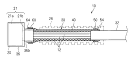
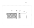
- FIG. 1 is a schematic cross-sectional view showing the wiring module 10.
- the wiring module 10 includes a plurality of covered electric wires 12 as at least one linear conductor, a connector 20 as an end part attached to one end of the plurality of covered electric wires 12, an electromagnetic shield member 30, and an external protection. Member 26.
- the plurality of covered electric wires 12 are bundled into one here.
- the covered electric wire 12 includes a core wire and a covering that covers the periphery of the core wire.
- the core wire is a linear member made of metal such as copper, copper alloy, aluminum, or aluminum alloy.
- the core wire may have a configuration in which a plurality of strands are twisted together, or may be configured by a single wire.
- the coating is an insulating member formed of resin or the like, and is formed so as to cover the core wire by extrusion coating or the like.
- the covered electric wire 12 may be only one.
- it is not essential that the covered electric wire 12 is used as the linear conductive wire, and a bare conductor that is not covered around may be used. In this case, the bare conductor may be covered with a heat shrinkable tube or the like.
- a connector 20 is attached to the tip of the plurality of covered electric wires 12.
- the connector 20 is a member formed of an insulating material such as resin.
- the connector 20 includes a housing main body 21a whose outer peripheral surface has a rectangular parallelepiped outer peripheral surface shape, and a connecting portion 21b connected to one end of the housing main body 21a (the end on the side to which the covered electric wire 12 is connected). Is provided.
- the connecting portion 21b is formed in a shape (here, a rectangular parallelepiped shape) that is thinner than the housing main body portion 21a.
- the terminal portion corresponding to each covered electric wire 12 is incorporated in the housing portion 21.
- Each terminal portion is connected to the core wire of the covered electric wire 12.
- Each terminal part and the core wire are connected by ultrasonic welding, resistance welding, soldering, crimping, or the like.
- this terminal portion is embedded in the housing portion 21 by insert molding or the like in a state where the connecting portion with the conductor of the covered electric wire 12 is embedded in the housing portion 21 and the connecting portion on the opposite side is projected. Yes.
- the connecting portion of the terminal portion is exposed on the opposite side of the housing main body portion 21a from the connecting portion 21b.
- connection part is a part provided for connection to the external electrical component side, and is a round terminal shape with a screw hole, a cylindrical female terminal shape, or a pin shape or tab shape. It is formed in a male terminal shape or the like.
- the covered electric wire 12 including the core wire connected to the terminal portion extends outward from the connecting portion 21 b side of the housing portion 21.
- the connector 20 is connected to various electrical components mounted on the vehicle, and the covered electric wire 12 is electrically connected to the electrical components.
- the electromagnetic shield member 30 includes a metal pipe 32 and a metal shell 36 as metal members, a cylindrical conductive member 40 constituted by a metal wire 40a, and ring members 50 and 60.
- a metal pipe 32 is connected to one end of the cylindrical conductive member 40
- a metal shell 36 is connected to the other end of the cylindrical conductive member 40.
- the metal shell 36 covers the outer periphery of the connector 20, and the cylindrical conductive member 40 and the metal pipe 32 cover the covered electric wire 12 extending from the connector 20.
- this electromagnetic shielding member 30 electromagnetically shields between the electric path
- the ring member 50 is provided at a connecting portion between the cylindrical conductive member 40 and the metal pipe 32, and the ring member 60 is used at a connecting portion between the cylindrical conductive member 40 and the metal shell 36.
- the electromagnetic shielding member 30 includes both the metal pipe 32 and the metal shell 36. Even when the electromagnetic shield member 30 includes both the metal pipe 32 and the metal shell 36, the connecting portion between the cylindrical conductive member 40 and the metal pipe 32, the cylindrical conductive member 40, and the metal shell 36. It is not necessary to apply the connection configuration using the ring members 50 and 60 to both of the connection portions.
- the metal shell 36 is a member formed by press-molding a metal plate such as aluminum, aluminum alloy, copper, copper alloy, stainless steel, or iron, and the periphery of the housing main body 21a and the connecting portion 21b of the connector 20 It is formed in a box shape covering.
- the metal shell 36 is opened on the outward side of the connecting portion 21b and on the opposite side.
- the cylindrical part 36b surrounding the connecting part 21b in the metal shell 36 covers the end part of the covered electric wire 12 on the side connected to the terminal.
- the metal shell 36 is an example of a metal member having a cylindrical portion 36b.
- the metal pipe 32 is a member formed in a cylindrical shape in which the covered electric wire 12 can be disposed.
- the metal pipe 32 is a metal member formed of a metal such as aluminum, stainless steel, or iron.
- the metal pipe 32 has a role of covering and protecting a portion of the covered electric wire 12 away from the connector 20 and a role of performing electromagnetic shielding. Since the entire extending direction of the metal pipe 32 has a cylindrical shape, the metal pipe 32 is a kind of metal member having a cylindrical portion.
- the metal pipe 32 may be a cylinder formed by combining semi-cylindrical members.
- An insulating coating layer may be formed on the outer periphery of the metal pipe 32. The insulating coating layer can be formed by thermally shrinking the heat-shrinkable tube or applying an insulating paint. But it is preferable that the insulation coating layer is formed except the location where the cylindrical conductive member 40 is connected among the metal pipes 32.
- the reason why the metal pipe 32 is provided at a position spaced from the connector 20 is to allow the covered electric wire 12 to be bent between the metal pipe 32 and the connector 20. That is, since the metal pipe 32 is a relatively hard member, it also serves to maintain the covered wire 12 in a predetermined path shape. However, if the entire covered electric wire 12 is not bent, it is difficult to assemble the wiring module 10 in the vehicle. Then, while fixing the metal pipe 32 to a vehicle and making the connector 20 easy to bend in a state where the connector 20 is connected to an electric part of the vehicle, their workability can be improved.
- the cylindrical conductive member 40 is a member formed into a cylindrical shape by knitting a metal wire 40a.
- the cylindrical conductive member 40 is, for example, a braid in which metal wires are knitted in a cylindrical shape, a metal cloth having a mesh structure woven so that metal wires intersect vertically and horizontally, or a metal mesh is rounded so as to form a cylinder shape. It is assumed that the configuration is the same.
- the end of one side of the cylindrical conductive member 40 is covered with the end of the metal pipe 32.
- a ring member 50 is provided on the outer periphery of the portion of the cylindrical conductive member 40 that is covered with the metal pipe 32.
- the filler material described later is melted and solidified, so that a joining portion 54 that is preferably in contact with the metal pipe 32 and the ring member 50 and joins the cylindrical conductive member 40 to the metal pipe 32 is formed.
- the other end portion of the cylindrical conductive member 40 is covered with the cylindrical portion 36 b of the metal shell 36.
- the ring member 60 is provided in the outer periphery of the part covered on the cylinder part 36b among the cylindrical conductive members 40.
- a joining portion 64 is formed by melting and solidifying the filler material described later, preferably in contact with the tubular portion 36b and the ring member 50 and joining the tubular conductive member 40 to the tubular portion 36b.
- a joining portion 64 is formed by melting and solidifying the filler material described later, preferably in contact with the tubular portion 36b and the ring member 50 and joining the tubular conductive member 40 to the tubular portion 36b.
- the external protection member 26 covers a portion of the covered electric wire 12 between the connector 20 and the metal pipe 32.
- a bendable member such as a corrugated tube is preferably used.
- connection portion between the metal pipe 32 and the cylindrical conductive member 40 will be described more specifically.
- connection part of the cylindrical part 36b of the metal shell 36 and the cylindrical conductive member 40 is the same as the structure regarding the connection part of the metal pipe 32 and the cylindrical conductive member 40. Description will be made centering on the configuration of the connecting portion with the metal pipe 32.
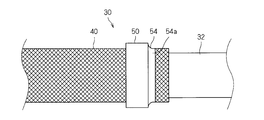
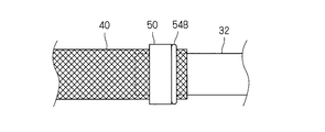
- FIG. 2 is a side view showing a connecting portion between the metal pipe 32 and the cylindrical conductive member 40
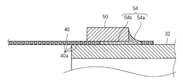
- FIG. 3 is a partial cross-sectional view showing a connecting portion between the metal pipe 32 and the cylindrical conductive member 40.
- the ring member 50 is a short cylindrical member.
- the ring member 50 is a metal member formed of aluminum, an aluminum alloy, copper, a copper alloy, or the like.
- the inner diameter dimension of the ring member 50 is larger than the outer diameter dimension of the metal pipe 32, and is set to a size that allows the cylindrical conductive member 40 to be sandwiched between the ring member 50 and the metal pipe 32. For this reason, the ring member 50 presses the cylindrical conductive member 40 against the outer peripheral surface of the metal pipe 32 in the entire circumferential direction of the metal pipe 32.
- the joining portion 54 is preferably in contact with the metal pipe 32 and the ring member 50 to join the cylindrical conductive member 40 to the metal pipe 32. More specifically, the joint portion 54 is provided at a first corner provided between an end surface of the ring member 50 and a portion of the outer peripheral surface of the metal pipe 32 facing the one end surface of the ring member 50. It includes a joint 54 a and a second joint 54 b interposed between the inner peripheral surface of the ring member 50 and the outer peripheral surface of the metal pipe 32.
- the fact that a certain object is interposed between two other objects means that the certain object exists between two other objects. Therefore, the second joint portion 54b is formed inside the ring member 50. It exists between the peripheral surface and the outer peripheral surface of the metal pipe 32.
- the first joint portion 54a extends along the circumferential direction of one end surface of the ring member 50, and joins the cylindrical conductive member 40 to the outer circumferential surface of the metal pipe 32 in the entire circumferential direction.
- the second joint portion 54 b extends along the circumferential direction of the inner circumferential surface of the ring member 50, and a portion of the cylindrical conductive member 40 located on the inner circumferential side of the ring member 50 is the outer circumference of the metal pipe 32. Bonded to the surface. For this reason, the cylindrical conductive member 40 is joined to the outer peripheral surface of the metal pipe 32 by the joint portion 54 at positions outside the inner peripheral surface and one end surface of the ring member 50.
- the joint portion may be partially formed in the circumferential direction of the ring member 50.
- the joint portion may include only one of the first joint portion 54a and the second joint portion 54b.
- the joint 54 is joined to the surface of the metal wire 40 a in a state of enclosing the metal wire 40 a of the cylindrical conductive member 40 and to the surface of the metal pipe 32. For this reason, the cylindrical conductive member 40 is mechanically connected by the joint portion 54 so as not to leave the surface of the metal pipe 32.
- the joining portion 54 is formed of a metal and has conductivity, and at least one of maintaining the tubular conductive member 40 in contact with the metal pipe 32, the tubular conductive member 40. Is electrically connected to the metal pipe 32.
- the surface of the metal pipe 32 and the cylindrical conductive member 40 formed of aluminum or an aluminum alloy is oxidized. A film is formed. This oxide film prevents electrical connection between the metal pipe 32 and the cylindrical conductive member 40. Therefore, as described above, when the metal pipe 32 and the cylindrical conductive member 40 are joined at the joint portion 54 formed by melting the filler material, the oxide film is destroyed or removed when the filler material is melted. . For this reason, at least one of the metal pipe 32 and the cylindrical conductive member 40 is formed of aluminum or an aluminum alloy to reduce the weight, and the metal pipe 32 and the cylindrical conductive member 40 are electrically connected favorably. be able to.
- both the metal pipe 32 and the cylindrical conductive member 40 are formed of aluminum or an aluminum alloy, the oxide films on both surfaces of the metal pipe 32 and the cylindrical conductive member 40 are reduced while further reducing the weight. They can be destroyed or removed and connected well. Moreover, dissimilar metal contact corrosion between the metal pipe 32 and the cylindrical conductive member 40 can be suppressed.
- the filler material it is preferable to select a filler material having good wettability with respect to the metal pipe 32, the cylindrical conductive member 40 and the ring member 50 and having a melting point lower than those.
- both the metal pipe 32 and the cylindrical conductive member 40 are formed of aluminum or an aluminum alloy
- a filler material that can be used for brazing the aluminum or aluminum alloy can be used as the filler material.
- an aluminum alloy containing silicon can be used as an example of such a filler material.
- the joining portion 54 melts and solidifies the aluminum alloy containing silicon so that the cylindrical conductive member 40 is connected to the metal pipe 32. It is formed as being in a state of being joined to.
- the melting point can be adjusted by the ratio of silicon.
- the ring member 50 a material having a melting point higher than that of the filler material and good wettability of the filler material can be used.
- a filler material that can be used for brazing the aluminum or aluminum alloy is selected. For this reason, it is preferable that the ring member 50 is formed of aluminum or an aluminum alloy.
- the metal pipe 32, the cylindrical conductive member 40, and the ring member 50 are formed of aluminum or an aluminum alloy, and the filler material is formed of an aluminum alloy (for example, an alloy containing silicon as described above).
- the filler material is formed of an aluminum alloy (for example, an alloy containing silicon as described above).
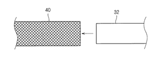
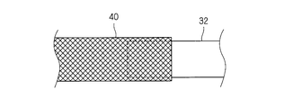
- a metal pipe 32 and a cylindrical conductive member 40 are prepared.
- the end of the metal pipe 32 is inserted into the cylindrical conductive member 40. It can also be said that the end of the cylindrical conductive member 40 is put on the outer periphery of the end of the metal pipe 32. Thereby, the edge part of the cylindrical conductive member 40 is arrange
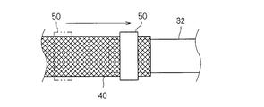
- the ring member 50 is disposed on the outer periphery of the portion of the cylindrical conductive member 40 that is covered with the metal pipe 32. Thereby, the cylindrical conductive member 40 can be pressed against the outer peripheral surface of the metal pipe 32 (step (b)).
- the ring member 50 is fitted from the end of the cylindrical conductive member 40 opposite to the metal pipe 32, and the ring member 50 is connected to the end of the metal pipe 32 along the cylindrical conductive member 40. It is good to carry out by moving toward the outer periphery of the part. Thereby, the end of the cylindrical conductive member 40 can be sandwiched between the metal pipe 32 and the ring member 50. In this example, only one ring member 50 is used.
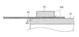
- the filler material 54 ⁇ / b> B is disposed at a position on the outer peripheral surface side of the metal pipe 32 and where the end of the cylindrical conductive member 40 is disposed (step (c)).
- the filler material 54B is a solder, a brazing material, or the like, and a metal having good wettability with respect to the metal pipe 32 and the cylindrical conductive member 40 and having a melting point lower than those is used.
- the filler material 54B exhibits good wettability even with respect to the ring member 50, and will be described here on the basis thereof.
- the filler material 54 ⁇ / b> B is provided, for example, in a thread form, and is disposed at the above-described location by being wound around the outer periphery of the cylindrical conductive member 40 around the metal pipe 32.
- the number of windings of the filler material 54B is preferably one or more times.
- the filler material 54 ⁇ / b> B is preferably disposed at a position in contact with or close to the end surface of the ring member 50.
- the filler material may be provided in a plate-like or granular form.
- the order of the above steps (a), (b) and (c) is arbitrary.
- the ring member 50 may be disposed at the above location.
- the operation of arranging the cylindrical conductive member 40 on the outer peripheral side of the metal pipe 32 and the ring member 50 may be provided at the above-mentioned locations.
- the filler material 54B is attached and integrated in advance with respect to the ring member 50, and the ring member 50 and the filler material 54B are attached to the outer periphery of the cylindrical conductive member 40 around the metal pipe 32 at the same time. Also good.
- the ring member and the filler material can be integrated by forming a groove in the inner periphery of the ring member and setting the filler material in the groove.
- the arrangement position of the filler material 54B is not limited to the above example.
- the filler material may be disposed on the inner peripheral side of the ring member.
- the filler material is disposed at a location different from the location where the ring member presses the cylindrical conductive member toward the outer peripheral surface of the metal pipe. Preferably it is.
- the filler material 54 ⁇ / b> B is heated and melted, and the melted filler material 54 ⁇ / b> B comes into contact with the metal pipe 32 and the ring member 50 to connect the cylindrical conductive member 40 to the metal pipe. 32 to join.
- the heating can be performed by arranging the metal pipe 32, the cylindrical conductive member 40, the metal pipe 32, and the filler material 54B in the heating furnace 70, high frequency induction heating, heating by a burner, or the like.
- the melted filler material 54 ⁇ / b> B Since the melted filler material 54 ⁇ / b> B has good wettability with respect to the metal pipe 32, the ring member 50, and the cylindrical conductive member 40, the melted filler material 54 ⁇ / b> B is directed to the end surface of the end surface of the ring member 50 and the outer peripheral surface of the metal pipe 32. When it spreads between the metal wires 40a between the mating portions and solidifies at that portion, it becomes the first joint portion 54a that joins the cylindrical conductive member 40 to the surface of the metal pipe 32.
- the melted filler material 54 ⁇ / b> B has good wettability with respect to the metal pipe 32, the ring member 50, and the cylindrical conductive member 40, and thus the inner peripheral surface of the ring member 50 and the outer peripheral surface of the metal pipe 32. Between the metal wires 40a and spreads between the metal wires 40a. Then, when the melted filler material 54B is solidified between the inner peripheral surface of the ring member 50 and the outer peripheral surface of the metal pipe 32, a second joint portion 54b that joins the cylindrical conductive member 40 to the surface of the metal pipe 32; Become.
- the filler material 54 ⁇ / b> B melts and then solidifies to become the joint portion 54, so that the cylindrical conductive member 40 is pressed against the metal pipe 32. Both states can be fixed and bonded together. Further, since the melted filler material 54B accumulates along the surface of the ring member 50 around the portion where the ring member 50 presses the cylindrical conductive member 40 and solidifies to form the joint portion 54, from this point In addition, the cylindrical conductive member 40 can be reliably joined by the metal pipe 32.
- the end of the cylindrical conductive member 40 is disposed on the outer peripheral surface of the metal pipe 32, and the cylindrical conductive member is formed by the ring member 50. Since the end of 40 is pressed against the outer peripheral surface of the metal pipe 32, brazing can be performed with the ring member 50 pressing the cylindrical conductive member 40 against the outer peripheral surface of the metal pipe 32. Further, the melted filler material 54B is in a state of joining the cylindrical conductive member 40 to the metal pipe 32 to form the joint portion 54, so that the melted melt material 54B is difficult to spread around. For this reason, the cylindrical conductive member 40 formed by knitting the metal wire 40 a can be easily brazed to the metal pipe 32.
- the joint portion 54 extends over the entire circumferential direction of the metal pipe 32.
- the cylindrical conductive member 40 can be joined to the outer periphery of the metal pipe 32 by the joining portion 54 that extends easily in the circumferential direction of the ring member 50.
- one of the metal pipe 32 and the cylindrical conductive member 40 is formed of aluminum or an aluminum alloy
- an oxide film on the surface of the metal pipe 32 or the cylindrical conductive member 40 formed of aluminum or an aluminum alloy Can be destroyed or removed when brazing, and the cylindrical conductive member 40 can be satisfactorily connected to the metal pipe 32.
- both the metal pipe 32 and the cylindrical conductive member 40 are formed of aluminum or an aluminum alloy, the cylindrical conductive member 40 can be satisfactorily connected to the metal pipe 32 while reducing the weight of the electromagnetic shield member 30. .
- an aluminum alloy containing silicon has a lower melting point than aluminum and is suitable for brazing aluminum or an aluminum alloy.
- the cylindrical conductive member 40 can be easily attached to the metal pipe 32. Can be joined.
- the filler material 54B when a material suitable for aluminum or an aluminum alloy is used as the filler material 54B, when the ring member 50 is formed of aluminum or an aluminum alloy, the ring member 50 is also satisfactorily bonded to the bonding portion 54. . For this reason, the ring member 50 also contributes to improving the connection strength between the cylindrical conductive member 40 and the cylindrical conductive member 40.
- the cylindrical conductive member 40 can be made of metal with a relatively small amount of filler material. It can be joined to the pipe 32. For example, even when there is only one ring member 50, the cylindrical conductive member 40 can be joined to the metal pipe 32 by the joint portion inside the ring member 50.
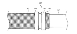
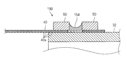
- a plurality of ring members 50 are provided at intervals along the axial direction of the metal pipe 32, and the joint portions 154 are formed of the plurality of ring members 50.
- the cylindrical conductive member 40 may be joined to the metal pipe 32 with a gap therebetween.
- the ring members 50 are provided at a plurality of locations at intervals along the axial direction of the metal pipe 32, and the filler material 154 ⁇ / b> B is disposed between the plurality of ring members 50.
- the melt material 154B is heated and melted, and the melted melt material 154B is held between the plurality of ring members 50, and the melt material 154B melted at that portion. It is good to solidify and form the junction part 154 which joins the cylindrical electrically-conductive member 40 to the metal pipe 32.
- the cylindrical conductive member 40 can be more reliably joined to the metal pipe 32 by the joining portion 154 between the plurality of ring members 50. Even in this case, a part of the joint 154 may enter between the metal pipe 32 and the ring member 50.
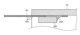
- the end portion of the cylindrical conductive member 40 is disposed on the inner peripheral surface side of the metal pipe 32, and the ring member 250 is fitted on the inner peripheral surface side to form a cylindrical shape.
- the joint portion 254 is in contact with the inner peripheral surface of the metal pipe 32 and the ring member 250 and the cylindrical conductive member 40 and the metal pipe 32. It may be in a state where it is joined.
- the pressing members that press the cylindrical conductive member 40 against the metal pipe 32 are the ring members 50 and 250
- the ring shape is not necessarily required.
- the pressing member may be a member that can press the cylindrical conductive member against the metal pipe at a plurality of locations around the metal pipe, and the joint may be formed between the plurality of pressing locations around the metal pipe.
- a plurality of ring members may be provided at intervals, and a joint may be formed between them, as in the modification shown in FIGS. 12 and 13.
- Electromagnetic shielding member 32 Metal pipe 36 Metal shell 36b Cylindrical part 40 Cylindrical conductive member 40a Metal wire 50, 60, 250 Ring member 54, 64, 154 Join part 54B, 154B, 254 Filler material 54a First 1 junction 54b 2nd junction
Landscapes
- Engineering & Computer Science (AREA)
- Microelectronics & Electronic Packaging (AREA)
- Manufacturing & Machinery (AREA)
- Civil Engineering (AREA)
- Electromagnetism (AREA)
- Architecture (AREA)
- Physics & Mathematics (AREA)
- Structural Engineering (AREA)
- Insulated Conductors (AREA)
- Shielding Devices Or Components To Electric Or Magnetic Fields (AREA)
- Manufacturing Of Electric Cables (AREA)
- Processing Of Terminals (AREA)
- Details Of Indoor Wiring (AREA)
Priority Applications (2)
| Application Number | Priority Date | Filing Date | Title |
|---|---|---|---|
| US16/303,404 US20190221328A1 (en) | 2016-05-20 | 2017-05-10 | Electromagnetic shielding member, wiring module, and method for manufacturing electromagnetic shielding member |
| CN201780030231.9A CN109156094B (zh) | 2016-05-20 | 2017-05-10 | 电磁屏蔽构件、布线模块以及电磁屏蔽构件的制造方法 |
Applications Claiming Priority (2)
| Application Number | Priority Date | Filing Date | Title |
|---|---|---|---|
| JP2016101292A JP6614026B2 (ja) | 2016-05-20 | 2016-05-20 | 電磁シールド部材、配線モジュール及び電磁シールド部材の製造方法 |
| JP2016-101292 | 2016-05-20 |
Publications (1)
| Publication Number | Publication Date |
|---|---|
| WO2017199814A1 true WO2017199814A1 (ja) | 2017-11-23 |
Family
ID=60325813
Family Applications (1)
| Application Number | Title | Priority Date | Filing Date |
|---|---|---|---|
| PCT/JP2017/017686 Ceased WO2017199814A1 (ja) | 2016-05-20 | 2017-05-10 | 電磁シールド部材、配線モジュール及び電磁シールド部材の製造方法 |
Country Status (4)
| Country | Link |
|---|---|
| US (1) | US20190221328A1 (enExample) |
| JP (1) | JP6614026B2 (enExample) |
| CN (1) | CN109156094B (enExample) |
| WO (1) | WO2017199814A1 (enExample) |
Families Citing this family (3)
| Publication number | Priority date | Publication date | Assignee | Title |
|---|---|---|---|---|
| JP7640313B2 (ja) * | 2021-03-19 | 2025-03-05 | 古河電気工業株式会社 | シールド外装および該シールド外装に備えられたワイヤーハーネス |
| JP7727491B2 (ja) * | 2021-11-09 | 2025-08-21 | 古河As株式会社 | 電磁シールド構造の製造方法 |
| CN114243390B (zh) * | 2021-12-14 | 2024-05-07 | 陕西航空电气有限责任公司 | 一种航空发动机点火电缆防波套组件连接结构 |
Citations (2)
| Publication number | Priority date | Publication date | Assignee | Title |
|---|---|---|---|---|
| JP2006164702A (ja) * | 2004-12-06 | 2006-06-22 | Hitachi Cable Ltd | シールド電線 |
| WO2015118937A1 (ja) * | 2014-02-06 | 2015-08-13 | 株式会社オートネットワーク技術研究所 | 電磁シールド部品および電磁シールド部品付電線 |
Family Cites Families (13)
| Publication number | Priority date | Publication date | Assignee | Title |
|---|---|---|---|---|
| FI55906C (fi) * | 1968-09-19 | 1979-10-10 | Aga Ab | Skarvdon foer foerbindning av pao utsidan slaeta roer |
| GB1424068A (en) * | 1973-04-10 | 1976-02-04 | Standard Telephones Cables Ltd | Jointing arrangement for a coaxial core |
| US4468080A (en) * | 1981-06-22 | 1984-08-28 | Automation Industries, Inc. | Cable shield termination means for plug and receptacle connectors |
| US4832248A (en) * | 1986-11-20 | 1989-05-23 | Raychem Corporation | Adhesive and solder connection device |
| US4858310A (en) * | 1988-04-12 | 1989-08-22 | W. L. Gore & Associates, Inc. | Method for soldering a metal ferrule to a flexible coaxial electrical cable |
| KR0173782B1 (ko) * | 1989-10-09 | 1999-02-01 | 나가노 다께시 | 전기 또는 전자회로의 성형에 사용되는 세라믹기판 |
| US6107572A (en) * | 1994-07-29 | 2000-08-22 | Sumitomo Wiring Systems, Ltd. | Terminal-processed structure of shielded cable and terminal-processing method of the same |
| JP2007080692A (ja) * | 2005-09-14 | 2007-03-29 | Auto Network Gijutsu Kenkyusho:Kk | シールド導電体 |
| JP2008006480A (ja) * | 2006-06-30 | 2008-01-17 | Sumitomo Light Metal Ind Ltd | 熱交換器用ブレージングフィン材並びに熱交換器及びその製造方法 |
| MX2011008140A (es) * | 2009-02-05 | 2011-08-17 | 3M Innovative Properties Co | Montaje de empalme con funda de proteccion. |
| JP5697232B2 (ja) * | 2010-09-02 | 2015-04-08 | 矢崎総業株式会社 | シールドコネクタ |
| JP2012182016A (ja) * | 2011-03-01 | 2012-09-20 | Auto Network Gijutsu Kenkyusho:Kk | シールド導電体 |
| JP6044475B2 (ja) * | 2013-07-04 | 2016-12-14 | 住友電装株式会社 | シールド導電体の製造方法 |
-
2016
- 2016-05-20 JP JP2016101292A patent/JP6614026B2/ja active Active
-
2017
- 2017-05-10 WO PCT/JP2017/017686 patent/WO2017199814A1/ja not_active Ceased
- 2017-05-10 CN CN201780030231.9A patent/CN109156094B/zh active Active
- 2017-05-10 US US16/303,404 patent/US20190221328A1/en not_active Abandoned
Patent Citations (2)
| Publication number | Priority date | Publication date | Assignee | Title |
|---|---|---|---|---|
| JP2006164702A (ja) * | 2004-12-06 | 2006-06-22 | Hitachi Cable Ltd | シールド電線 |
| WO2015118937A1 (ja) * | 2014-02-06 | 2015-08-13 | 株式会社オートネットワーク技術研究所 | 電磁シールド部品および電磁シールド部品付電線 |
Also Published As
| Publication number | Publication date |
|---|---|
| JP6614026B2 (ja) | 2019-12-04 |
| JP2017208499A (ja) | 2017-11-24 |
| US20190221328A1 (en) | 2019-07-18 |
| CN109156094B (zh) | 2020-03-31 |
| CN109156094A (zh) | 2019-01-04 |
Similar Documents
| Publication | Publication Date | Title |
|---|---|---|
| JP6278272B2 (ja) | 導電線及びその配索構造 | |
| JP6673404B2 (ja) | 導電部材 | |
| JP6251767B2 (ja) | 電磁干渉スプライスシールド | |
| JP6048859B2 (ja) | 導電線、導電線の製造方法及び導電線の配索構造 | |
| JP6582649B2 (ja) | シールド構造 | |
| CN102842774B (zh) | 电缆的连接结构和连接方法 | |
| WO2013175902A1 (ja) | 端子付き電線およびその製造方法、ならびに治具 | |
| JP4720168B2 (ja) | シールド電線 | |
| JP6376078B2 (ja) | 筒状導電性編組及び電磁シールド付配線モジュール | |
| JP6890222B2 (ja) | インダクター部品 | |
| JP6614026B2 (ja) | 電磁シールド部材、配線モジュール及び電磁シールド部材の製造方法 | |
| JP2017212313A (ja) | 電磁シールド部材、配線モジュール及び電磁シールド部材の製造方法 | |
| JP4691972B2 (ja) | シールド電線及びその製造方法 | |
| JP5527376B2 (ja) | シールド電線 | |
| JP2017073312A (ja) | 端子付電線及び熱収縮チューブ | |
| JP5640907B2 (ja) | ワイヤハーネス及びワイヤハーネスの製造方法 | |
| JP7727491B2 (ja) | 電磁シールド構造の製造方法 | |
| JP5168016B2 (ja) | シールド電線 | |
| JP2013196989A (ja) | 電線の接合構造 | |
| JP2024082856A (ja) | 電磁シールド構造、電磁シールド構造の製造方法 | |
| CN121646852A (zh) | 线束 | |
| JP2015076329A (ja) | 端子付電線 | |
| JP2017183154A (ja) | 熱収縮チューブ付電線の製造方法 | |
| JP2017126403A (ja) | シールド電線及びシールド電線の製造方法 | |
| JP2014067573A (ja) | 被覆電線と端子金具のシール構造および被覆電線と端子金具のシール方法 |
Legal Events
| Date | Code | Title | Description |
|---|---|---|---|
| NENP | Non-entry into the national phase |
Ref country code: DE |
|
| 121 | Ep: the epo has been informed by wipo that ep was designated in this application |
Ref document number: 17799239 Country of ref document: EP Kind code of ref document: A1 |
|
| 122 | Ep: pct application non-entry in european phase |
Ref document number: 17799239 Country of ref document: EP Kind code of ref document: A1 |