WO2017199709A1 - 顔向き推定装置及び顔向き推定方法 - Google Patents
顔向き推定装置及び顔向き推定方法 Download PDFInfo
- Publication number
- WO2017199709A1 WO2017199709A1 PCT/JP2017/016322 JP2017016322W WO2017199709A1 WO 2017199709 A1 WO2017199709 A1 WO 2017199709A1 JP 2017016322 W JP2017016322 W JP 2017016322W WO 2017199709 A1 WO2017199709 A1 WO 2017199709A1
- Authority
- WO
- WIPO (PCT)
- Prior art keywords
- driver
- face orientation
- visual
- behavior
- unit
- Prior art date
- Legal status (The legal status is an assumption and is not a legal conclusion. Google has not performed a legal analysis and makes no representation as to the accuracy of the status listed.)
- Ceased
Links
Images


Classifications
-
- G—PHYSICS
- G08—SIGNALLING
- G08G—TRAFFIC CONTROL SYSTEMS
- G08G1/00—Traffic control systems for road vehicles
- G08G1/16—Anti-collision systems
Definitions
- the present disclosure relates to a face direction estimation device and a face direction estimation method for estimating the face direction of a driver who drives a vehicle or the like.
- Patent Document 1 discloses a technique in which a driver's face driving a moving body such as a vehicle is photographed by a camera and the driver's face orientation is recognized based on the photographed image. Specifically, the attention reduction detection system of Patent Document 1 counts the number of times the driver visually recognizes the side mirror installed in the vehicle based on the recognized face orientation. Then, based on the counted number of times the side mirror is visually recognized, a decrease in the driver's attention is determined.
- the face orientation when the driver is viewing the side mirror differs depending on the driver's physique, sitting position, sitting posture, and the like. Therefore, the inventors of the present disclosure specify the position of the visual recognition object from the visual behavior of the driver, and compare the position of the visual recognition object thus identified with the recognized driver's face direction. We have been developing a technology that counts the number of times a visual target is viewed.
- the inventors of the present disclosure have a problem that the accuracy of counting the number of visual recognitions is reduced due to road environments such as curves and slopes. Newly discovered. More specifically, the driver usually changes the face direction from the vanishing point to the visual recognition object with the vanishing point in the foreground as the zero point position. Therefore, when traveling on a curve, a slope, or the like, if the position of the vanishing point in the foreground changes, the mode of visual behavior that changes the face direction from the vanishing point to the visual target object also changes. For this reason, if the driver's visual behavior changes due to the position change of the vanishing point, the number of times the driver visually recognizes the visual target object may not be counted correctly.
- the present disclosure relates to a face direction estimation device and a face direction that can accurately count the number of times a driver visually recognizes a visual target object even if the driver's visual behavior changes due to a change in the position of the vanishing point.
- An object is to provide an estimation method.
- the face direction estimation device includes a face direction information acquisition unit that acquires a detection result of detecting a face direction of a driver who drives a moving body, and the face direction information acquisition unit Based on the detection result, the counting processing unit that counts the number of times the driver visually recognizes the visual target object installed on the moving body, and due to the position change of the vanishing point in the foreground visually recognized by the driver An action determination unit that determines whether or not the driver's visual action for visually recognizing the visual target object has changed. When the behavior determination unit determines that the driver's visual behavior has changed, the counting processing unit changes the content of the counting process in accordance with the position change of the vanishing point.
- the driver's visual behavior changes due to such a position change. Can be determined.
- the process of counting the number of times the driver visually recognizes the visual target object installed on the moving body is changed to the content corresponding to the change in the driver's visual behavior in accordance with the change in the position of the vanishing point. Therefore, even if the driver's visual behavior changes due to the position change of the vanishing point, the number of times that the driver visually recognizes the visual target object can be accurately counted.
- a face direction estimation method for estimating a face direction of a driver who drives a moving body
- at least one processor includes a face direction detection unit that detects the face direction of the driver.
- the driver Based on the detection result, the driver counts the number of times the driver visually recognizes the visually recognized object installed on the moving body, and the visually recognized object is caused by a change in the position of the vanishing point in the foreground visually recognized by the driver. It is determined whether or not the driver's visual behavior has changed, and when it is determined that the driver's visual behavior has changed, the content of the counting process is changed in accordance with the position change of the vanishing point. To do.
- the driver's visual behavior changes due to such a position change. Can be determined.
- the process of counting the number of times the driver visually recognizes the visual target object installed on the moving body is changed to the content corresponding to the change in the driver's visual behavior in accordance with the change in the position of the vanishing point. Therefore, even if the driver's visual behavior changes due to the position change of the vanishing point, the number of times that the driver visually recognizes the visual target object can be accurately counted.
- FIG. 1 is a block diagram showing the entire face direction estimation system according to the first embodiment.
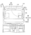
- FIG. 2 is a diagram showing a vehicle equipped with a face orientation estimation system
- FIG. 3 is a diagram showing a form of a wearable device
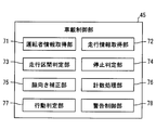
- FIG. 4 is a diagram showing functional blocks constructed in the in-vehicle controller.
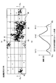
- 5 (a) and 5 (b) are diagrams showing a mode of a two-dimensional distribution of visual recognition points in a straight section and a histogram thereof.
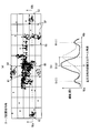
- 6 (a) and 6 (b) are diagrams showing a mode of a two-dimensional distribution of visual recognition points in the left curve section and a histogram thereof.
- FIG. 7 is a diagram illustrating a change in the line-of-sight direction to the yaw direction in a straight section and a threshold value for counting the number of times the left and right side mirrors are viewed.
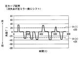
- FIG. 8 is a diagram illustrating a change in the line-of-sight direction to the yaw direction in the left curve section and a threshold value for counting the number of times the left and right side mirrors are viewed.
- FIG. 9 is a flowchart showing each process performed in the in-vehicle control unit.
- FIG. 10 is a diagram comparing the respective false detection and non-detection probabilities when detecting the visual behavior of the left and right side mirrors by the driver.
- FIG. 11 is a block diagram showing the entire face direction estimation system according to the second embodiment.
- the face orientation estimation system 100 includes a wearable device 10 and an in-vehicle device 40 that can communicate with each other, as illustrated in FIGS. 1 and 2.
- the face orientation estimation system 100 mainly functions in the passenger compartment of a vehicle 110 that is a moving object.
- the face direction estimation system 100 detects the behavior of the head HD of a driver DR who gets on the vehicle 110 and drives the vehicle 110 by the wearable device 10.
- the face orientation estimation system 100 uses the in-vehicle device 40 to calculate the face orientation of the driver DR from the detected behavior of the head HD.
- the driver DR's face direction information by the face direction estimation system 100 determines, for example, a decrease in the confirmation frequency for visually recognizing each mirror installed in the vehicle 110, a long look aside, terminal operation in the downward direction, and dozing. Used for applications that When an abnormality of the driver DR as described above is detected, an actuation such as a warning for the driver DR is executed.
- the wearable device 10 is a glasses-type motion sensor device in which the detection circuit 20 is mounted on the glasses 10a as shown in FIG.
- the wearable device 10 shown in FIGS. 1 and 2 is mounted on the head HD of the driver DR and sequentially outputs the face orientation detection results toward the in-vehicle device 40.
- the detection circuit 20 of the wearable device 10 includes a face direction detection unit 11, a communication unit 17, an operation unit 18, a battery 19, and the like.
- the face orientation detection unit 11 is a motion sensor mounted on the glasses 10a (see FIG. 3).
- the face orientation detection unit 11 detects a value related to the face orientation of the driver DR by mounting the wearable device 10 on the head HD of the driver DR.
- the face orientation detection unit 11 includes an electrooculogram sensor 12, a gyro sensor 13, and an acceleration sensor 14.
- the face orientation detection unit 11 sequentially provides the detection results acquired using the sensors 12 to 14 to the communication unit 17.
- the electrooculogram sensor 12 has a plurality of electrodes 12a (see FIG. 3) formed of a metal material such as stainless steel. Each electrode 12a is provided on the frame of the glasses 10a so as to be spaced apart from each other. When the driver DR as a user wears the wearable device 10, each electrode 12 a comes into contact with the skin of the driver DR in the vicinity of the eyeball of the driver DR.
- the electrooculogram sensor 12 measures the electrooculogram that changes with the eye movement of the driver DR based on the potential difference between two points of each electrode 12a. Measurement data (hereinafter referred to as “ocular potential data”) from the electrooculogram sensor 12 is sequentially provided to the communication unit 17 as a detection result.
- the gyro sensor 13 is a sensor that detects angular velocity as a voltage value.
- the gyro sensor 13 measures the magnitude of the angular velocity generated around each of the three axes that are orthogonal to each other defined by the face orientation detection unit 11 when the glasses 10a are attached to the head HD. Based on the angular velocity around each axis, there is an operation of shaking the head HD in the horizontal (yaw) direction, an operation of shaking the head HD in the vertical (pitch) direction, and an operation in the direction of tilting the head HD left and right (roll). Detected. Measurement data (hereinafter referred to as “angular velocity data”) by the gyro sensor 13 is sequentially provided to the communication unit 17 as a detection result.
- the acceleration sensor 14 is a sensor that detects acceleration as a voltage value.
- the acceleration sensor 14 measures the magnitude of acceleration acting on the head HD along the respective axial directions of the three axes defined in the face direction detection unit 11 by being worn on the head HD of the glasses 10a. To do.
- Data measured by the acceleration sensor 14 (hereinafter, “acceleration data”) is sequentially provided to the communication unit 17 as a detection result.
- the communication unit 17 can transmit / receive information to / from the in-vehicle device 40 by wireless communication using, for example, Bluetooth (registered trademark) and a wireless LAN.
- the communication unit 17 has an antenna corresponding to a wireless communication standard.
- the communication unit 17 is electrically connected to the face orientation detection unit 11 and acquires measurement data related to the face orientation output from the sensors 12 to 14.
- the communication unit 17 sequentially encodes each input measurement data and transmits it to the in-vehicle device 40.
- the operation unit 18 includes a power switch for switching the power of the wearable device 10 between an on state and an off state.
- the battery 19 is a power source that supplies power for operation to the face direction detection unit 11 and the communication unit 17.
- the battery 19 may be a primary battery such as a lithium battery or a secondary battery such as a lithium ion battery.
- the in-vehicle device 40 is one of a plurality of electronic control units mounted on the vehicle 110.
- the in-vehicle device 40 operates using electric power supplied from the in-vehicle power source.
- the in-vehicle device 40 is connected with an HMI control unit 50, a vehicle speed sensor 55, a locator 56, and the like.
- the in-vehicle device 40 may be configured so that it can be brought into the vehicle 110 by the driver and fixed to the vehicle body later.
- the HMI (Human Machine Interface) control unit 50 is one of a plurality of electronic control units mounted on the vehicle 110.
- the HMI control unit 50 controls the acquisition of the operation information input by the driver DR and the information presentation to the driver DR in an integrated manner.
- the HMI control unit 50 is connected to, for example, a display 51, a speaker 52, an input device 53, and the like.
- the HMI control unit 50 presents information to the driver DR by controlling the display on the display 51 and the sound output by the speaker 52.
- the vehicle speed sensor 55 is a sensor that measures the traveling speed of the vehicle 110.
- the vehicle speed sensor 55 outputs a vehicle speed pulse corresponding to the traveling speed of the vehicle 110 to the in-vehicle device 40.
- the vehicle speed information calculated based on the vehicle speed pulse may be supplied to the in-vehicle device 40 via an in-vehicle communication bus or the like.
- the locator 56 includes a GNSS receiver 57, a map database 58, and the like.
- a GNSS (Global Navigation Satellite System) receiver 57 receives positioning signals from a plurality of artificial satellites.
- the map database 58 stores map data including road shapes such as road longitudinal gradient and curvature.
- Locator 56 sequentially measures the current position of vehicle 110 based on the positioning signal received by GNSS receiver 57.
- the locator 56 reads out map data around the vehicle 110 and the traveling direction from the map database 58 and sequentially provides it to the in-vehicle device 40. As described above, the in-vehicle device 40 can acquire the shape information of the road on which the vehicle 110 is scheduled to travel.
- the in-vehicle device 40 connected to each of the above components includes a memory 46, a communication unit 47, and an in-vehicle control unit 45.
- the memory 46 is a non-transitional tangible storage medium such as a flash memory.
- the memory 46 stores an application program and the like necessary for the operation of the in-vehicle device 40. Data in the memory 46 can be read and rewritten by the in-vehicle control unit 45.
- the memory 46 may be configured to be built in the in-vehicle device 40, or may be configured to be inserted into a card slot provided in the in-vehicle device 40 in the form of a memory card or the like.
- the memory 46 has a first storage area 46a and a second storage area 46b. In each of the first storage area 46a and the second storage area 46b, data related to the detection result of the face orientation classified by the in-vehicle control unit 45 is accumulated, as will be described later.
- the communication unit 47 transmits and receives information to and from the wearable device 10 by wireless communication.
- the communication unit 47 has an antenna corresponding to a wireless communication standard.
- the communication unit 47 sequentially acquires measurement data from the sensors 12 to 14 by decoding the radio signal received from the communication unit 17.
- the communication unit 47 outputs each acquired measurement data to the in-vehicle control unit 45.
- the in-vehicle control unit 45 is mainly composed of a microcomputer having a processor 45a, a RAM, an input / output interface, and the like.
- the in-vehicle control unit 45 executes the face orientation estimation program stored in the memory 46 by the processor 45a.
- the in-vehicle control unit 45 includes a driver information acquisition unit 71, a travel information acquisition unit 72, a travel section determination unit 73, a stop determination unit 74, a face orientation correction unit 75, a count processing unit 76, an action shown in FIG.
- Functional blocks such as a determination unit 77 and a warning control unit 78 are constructed. The details of each functional block will be described below with reference to FIGS.
- the driver information acquisition unit 71 acquires the detection result by the face direction detection unit 11 received by the communication unit 47 from the communication unit 47. Specifically, the driver information acquisition unit 71 acquires electrooculogram data, angular velocity data, and acceleration data.
- the traveling information acquisition unit 72 sequentially acquires road shape information output from the locator 56. In addition, the travel information acquisition unit 72 acquires the current vehicle speed information of the vehicle 110 based on the vehicle speed pulse output from the vehicle speed sensor 55.
- the travel section determination unit 73 determines whether the vehicle 110 is traveling in a straight section and whether the vehicle 110 is traveling in a horizontal section without inclination. It is determined whether or not. Specifically, when the curvature of the road ahead of the vehicle is smaller than a predetermined threshold, the travel section determination unit 73 determines that the vehicle is traveling in a straight section. On the other hand, when the curvature of the road ahead of the vehicle is larger than the predetermined curvature, the traveling section determination unit 73 determines that the vehicle is traveling in a curved section instead of a straight section.
- the travel section determination unit 73 determines that the vehicle is traveling in a horizontal section.
- the traveling section determination unit 73 determines that the traveling section is traveling on a slope section that is not a horizontal section but an uphill or downhill.
- the stop determination unit 74 determines whether or not the vehicle 110 is in a stopped state. Specifically, the stop determination unit 74 is based on the vehicle speed information acquired by the travel information acquisition unit 72, when the travel speed is substantially zero, or the travel speed is less than a stop threshold (for example, 5 km / h). If it is, it is determined that the vehicle 110 is not in a running state but in a stopped state. On the other hand, when the traveling speed exceeds the above-described stop threshold, the stop determination unit 74 determines that the vehicle 110 is not in a stopped state but in a traveling state.
- a stop threshold for example, 5 km / h
- the stop determination unit 74 can determine whether or not the vehicle 110 is in a traveling state based on acceleration data from the acceleration sensor 14. Specifically, when the vertical vibration associated with traveling is not detected from the transition of the acceleration data and there is substantially no change in the longitudinal acceleration, the stop determination unit 74 indicates that the vehicle 110 is in the stop state. It is determined that
- the face orientation correction unit 75 estimates the line-of-sight direction of the driver DR by combining the electrooculogram data from the electrooculogram sensor 12 and the angular velocity data from the gyro sensor 13. Specifically, the face orientation correcting unit 75 calculates the angle of the head HD in each rotation direction by time-integrating the angular velocity around each axis. As described above, the face orientation correcting unit 75 estimates the face orientation of the driver DR caused by the swing of the driver DR.
- the face orientation correcting unit 75 estimates the eye movement of the driver DR based on the change mode of electrooculogram data using a so-called EOG (Electro-Oculography) method. Specifically, the face orientation correction unit 75 calculates the up / down / left / right directions in which the eyeballs are directed and the amount of change from the front of the eyeballs, based on the front direction of the face of the driver DR. The face direction correction unit 75 specifies the line-of-sight direction of the driver DR with reference to the vehicle 110 by correcting the estimated face direction by the amount of change in the direction of the eyeball.
- EOG Electro-Oculography
- the counting processing unit 76 counts the number of times the driver DR visually recognizes the visual recognition object, the plotting process that plots the line-of-sight direction of the driver DR, the specific process that specifies the position of the visual recognition object mounted on the vehicle 110. At least a counting process to be performed.
- the plot process, the specific process, and the counting process are performed when the stop determination unit 74 determines that the vehicle 110 is not in the stop state, and the stop determination unit 74 determines that the vehicle 110 is in the stop state. In case of failure, it can be interrupted.
- the driver's DR visual point VP (FIG. 5 (a) and FIG. 5 (b) is obtained by sampling the line-of-sight direction of the driver DR specified by the face direction correcting unit 75 at predetermined time intervals. ) See).
- the visual point VP of the driver DR is a geometrical relationship between a virtual curved surface defined to include the interior side surface of the windshield of the vehicle 110 and a virtual line defined to extend in the line-of-sight direction from the eyeball of the driver DR. This is an intersection.
- the virtual curved surface is defined as a shape that smoothly extends the windshield.
- each visual target object includes left and right side mirrors 111 and 112, a rearview mirror 113, a display 51, and a combination meter that are substantially fixed to the vehicle 110.
- the visual recognition object exists in a range where the visual recognition points VP are densely gathered (hereinafter, “aggregation part”).
- the central portion 61 of the windshield center where the most visible points VP gather is a vanishing point in the foreground of the driver DR. Then, each of the collective portions 62 to 66 in which the number of the visually recognized points VP plotted is the second or later becomes the position of each visually recognized object.
- the gathering portion 62 on the left edge of the windshield corresponds to the position of the left side mirror 111 (see FIG. 2).
- the gathering portion 63 on the right edge of the windshield corresponds to the position of the right side mirror 112 (see FIG. 2).
- the collecting unit 64 positioned above the collecting unit 61 corresponds to the position of the rearview mirror 113 (see FIG. 2).
- a set portion 65 located below each set portion 61, 64 corresponds to the position of the display 51 (see FIG. 1).
- the gathering part 66 located in the lower front of the driver DR corresponds to the position of the combination meter.
- 5A, 5B, 6A, and 6B the outermost edge of the horizontally long rectangular frame corresponds to the outer edge of the windshield.
- the position of the vanishing point in the foreground of the driver DR shown in FIG. 2 changes in the left-right direction or the up-down direction with respect to the vehicle 110 in a scene where the vehicle 110 is traveling in a curve section or a slope section.
- the position of the gathering unit 61 is also different in each viewing object during the period in which the vehicle 110 (see FIG. 2) is traveling in a curve section or a slope section. It changes relatively with respect to the other collecting portions 62 to 66 corresponding to the positions of the objects.
- the counting processing unit 76 classifies the position information of the plotted visual recognition points VP based on the road environment in which the vehicle 110 is traveling, and specifies the position of each visual recognition object. Is stored in the first storage area 46a or the second storage area 46b. Specifically, the position information of the visual point VP plotted in the period in which it is determined that the traveling section determination unit 73 is traveling in a horizontal and linear section is accumulated in the first storage area 46a.
- the position information of the visual recognition point VP plotted in the period determined to be traveling in the curve section or the slope section by the travel section determination unit 73 is excluded from the accumulation target in the first storage area 46a. . Then, the position information of the visual recognition point VP plotted in the curve section is associated with the curvature information indicating the magnitude of the curvature of the curve section and the curve direction of the curve, and is stored in the second storage area 46b. Similarly, the position information of the visual recognition point VP plotted in the slope section is associated with slope information indicating the magnitude of the vertical slope of the slope section and the vertical direction of the slope, and is stored in the second storage area 46b.
- the counting process the number of visual recognitions of each visual target by the driver DR is counted.
- the position of the collection target 61 corresponding to the vanishing point is used as a reference (zero point position), based on the transition of the relative change in the line-of-sight direction specified by the face orientation correction unit 75. The number of viewing times is counted (see FIGS. 7 and 8).
- a threshold is set for counting that each visual target object has been viewed.
- the threshold values in the vertical direction and the horizontal direction can be individually set for one visual object.
- the count processing unit 76 counts the number of times that the line-of-sight direction specified by the face orientation correcting unit 75 exceeds each threshold as the number of times of viewing each visual target object.
- a threshold th (r) in the right direction from a zero point position based on the position of the gathering unit 61 (see FIGS. 5A and 5B).
- the counting processing unit 76 counts that the right side mirror 112 (see FIG. 2) is viewed once.
- the line-of-sight direction exceeds the threshold th (l) (for example, 30 °) to the left from the zero point position based on the position of the gathering unit 61 (see FIGS. 5A and 5B).
- the counting process part 76 counts that the right side mirror 112 (refer FIG.
- the behavior determination unit 77 determines whether the visual recognition behavior of the driver DR who visually recognizes each visual target object has changed. As described above, in a scene where the vehicle 110 travels in a curve section or a slope section, the position of the vanishing point changes in the foreground visually recognized by the driver DR (see FIGS. 6A and 6B). ). The behavior determination unit 77 detects the occurrence of a change in the viewing behavior of the driver DR caused by the position change of the vanishing point.
- the behavior determination unit 77 can determine whether or not the visual behavior of the driver DR has changed based on the change in the detection result of the face direction detection unit 11. Specifically, the behavior determination unit 77 determines whether the viewing behavior of the driver DR has changed based on the behavior change of the behavior of visually recognizing the side mirror far from the driver DR, that is, the left side mirror 111. Determine whether or not. The behavior determination unit 77 determines whether or not the visual behavior of the driver DR has changed based on the frequency of viewing the left side mirror 111 (number of times per predetermined time) and the change in the pattern of viewing the left side mirror 111. Can be determined.
- the behavior determination unit 77 can detect a change in the visual behavior of the driver DR based on the determination result of the travel section determination unit 73. Specifically, the behavior determination unit 77 determines that the visual behavior of the driver DR has changed when the travel segment determination unit 73 determines that the vehicle travels in a curve section or a slope section. The determination result by the above action determination unit 77 is sequentially provided to the count processing unit 76.
- the counting processing unit 76 changes the content of the counting process so as to correspond to the position change of the vanishing point. Specifically, the counting processing unit 76, when the behavior determining unit 77 determines that the driver DR's visual behavior has changed, the aggregation unit 61 (see FIGS. 6A and 6B). Change the reference zero point position according to the slide position. As a result, as shown in FIGS. 5A to 8, each threshold value used for counting the number of times of visual recognition is changed.
- the collecting unit 61 shifts to the left side with respect to the vehicle 110, and the left side mirror It is close to the gathering portion 62 corresponding to 111 (see FIG. 2).
- the zero point position serving as the reference for the swing angle is also shifted to the left. Therefore, as shown in FIG. 8, the absolute value of the threshold th (r) for counting the number of times the right side mirror 112 is viewed is changed to a larger value (for example, 25 °) than when traveling in a straight section.
- the absolute value of the threshold th (l) for counting the number of times the left side mirror 111 is visually recognized is changed to a smaller value (for example, 20 °) than when traveling in a straight section.
- Specific values of the threshold values th (r) and th (l) are distributions of accumulated data corresponding to the road environment currently being traveled among the positional information of the visual recognition points VP accumulated in the second storage area 46b. Is set based on Therefore, the threshold values th (r) and th (l) change stepwise according to the curvature of the curve and the gradient.
- the warning control unit 78 acquires, from the counting processing unit 76, the number of times of viewing of each visual target object per predetermined time counted in the counting process.
- the warning control unit 78 determines whether or not the driver DR's visual behavior is in an abnormal state based on the obtained number of times of visual recognition of each visual target object. For example, when the frequency of visually recognizing the left and right side mirrors 111 and 112 falls below a predetermined frequency threshold, the warning control unit 78 determines that the state is abnormal.
- the warning control unit 78 outputs a command signal instructing execution of warning to the HMI control unit 50.
- a warning for the driver DR is performed by the display 51, the speaker 52, and the like.
- each process for estimating the face direction by the in-vehicle controller 45 described above will be described with reference to FIGS. 1 and 2 based on the flowchart of FIG.
- Each process shown in FIG. 9 is based on the fact that, for example, both the wearable device 10 and the in-vehicle device 40 are powered on, and transmission of the detection result from the wearable device 10 to the in-vehicle device 40 is started. Started by.
- Each process illustrated in FIG. 9 is repeatedly performed until at least one of the wearable device 10 and the in-vehicle device 40 is turned off.
- each threshold value for counting the number of times each visual object is viewed is set, the number of times the visual object is viewed is started, and the process proceeds to S103.
- a preset initial value is set as each threshold value.
- the traveling environment of the vehicle 110 is determined based on the distribution of the visual recognition points VP that started plotting in S101, the road shape information, the latest vehicle speed information, and the like, and the process proceeds to S104. If it is determined in S103 that the vehicle 110 is in a stopped state, the process returns from S104 to S103. Thus, when it is determined that the vehicle 110 is in the stopped state, the plot processing started in S101 may be temporarily interrupted until the vehicle 110 is switched to the traveling state. On the other hand, when it is determined in S103 that the vehicle 110 is in the traveling state, the process proceeds from S104 to S105.
- S105 it is determined whether the visual behavior has changed. If the determination result of the traveling environment is substantially the same as the conventional one in S103, it is determined in S105 that the visual behavior has not changed, and the process proceeds to S107. On the other hand, if a change in the determination result of the driving environment has occurred in S103, it is determined in S105 that the visual behavior has changed, and the process proceeds to S106.
- the threshold value corresponding to the traveling environment determined in the immediately preceding S103 is changed, and the process proceeds to S107.
- a counting process is performed to count the number of times each visual target is viewed using the currently set threshold values, and the process proceeds to S108.
- the identification of the line-of-sight direction of the driver DR and the plotting of the visual recognition point VP are continued, and the data of the plotted visual recognition point VP is accumulated in the respective storage areas 46a and 46b corresponding to the current driving environment, and in S109. move on.
- S109 it is determined whether or not the driver DR is in an abnormal state based on the result of the counting process performed in the immediately preceding S107.
- the process returns to S103.
- operator DR being in an abnormal state in S109, it progresses to S110.
- a command signal for instructing the HMI control unit 50 to execute a warning is output, and the series of processes is temporarily terminated. Based on the command signal output in S110, a warning by the display 51 and the speaker 52 is performed. When the warning in S110 ends, the vehicle-mounted control unit 45 starts S101 again.
- the driver DR when the vehicle 110 travels in a curve section, a slope section, or the like, and a change occurs in the position of the vanishing point in the foreground, the driver DR It is determined that the viewing behavior has changed. As a result, the counting process for counting the number of times that the driver DR visually recognizes the visual recognition object is changed to the content corresponding to the change in the visual recognition behavior of the driver DR in accordance with the position change of the vanishing point. Therefore, even if the driver DR's visual behavior changes due to the position change of the vanishing point, the number of times the driver visually recognizes the visual target object can be accurately counted.
- the detection result of the driver DR's face orientation surely changes.
- a clear change may occur in the visual recognition frequency of the visual object and the visual pattern of the visual object based on the detection result of the face orientation. Therefore, if it is determined whether or not there is a change in the viewing behavior of the driver DR based on the changes in the viewing frequency and the viewing pattern, the occurrence of the change in the viewing behavior due to the position change of the vanishing point can be detected without omission. Become.
- whether or not there is a change in the entire visual behavior due to the change in the position of the vanishing point is determined based on the behavior change of the behavior of visually recognizing the left side mirror 111 far from the driver DR. .
- the behavior change of the behavior of visually recognizing the left side mirror 111 far from the driver DR. For example, when visually recognizing the right side mirror 112, it is possible to move only by eye movement mainly by eye movement, so that the change in face orientation due to swinging becomes small.
- the amount of movement is insufficient only by the movement of the line of sight by eye movement, and thus a clear change in the face orientation due to swinging occurs.
- the behavior determination unit 77 can accurately determine the occurrence of the change in the behavior of the driver DR as a whole.
- the behavior determination unit 77 of the first embodiment can also determine the change in the visual behavior of the driver DR by using the determination result of the travel section determination unit 73.
- the vanishing point position change mainly occurs in the curve section and the slope section. Therefore, if the road shape information is used to specify the traveling of the curve section or the slope section, the behavior determination unit 77 accurately determines the occurrence of the change in the visual behavior due to the position change of the vanishing point without delay. be able to.
- the position information of the visual recognition point VP on which the face orientation detection result is plotted is accumulated in the first storage area 46a and used for specifying the position of the visual recognition object.
- the position information of the visual recognition point VP is continuously accumulated, the position of the visual recognition object can be specified with higher accuracy. As a result, it is possible to improve both the accuracy of determining the behavior change of the visual recognition behavior and the accuracy of counting the number of times the visual target is viewed.
- the position information of the visual recognition point VP acquired during the period determined by the traveling section determination unit 73 as not being a straight section is not accumulated in the first storage area 46a. According to such processing, only the position information of the visual recognition point VP in the period in which the position change of the vanishing point has not substantially occurred is accumulated in the first storage area 46a. Therefore, based on the position information accumulated in the first storage area 46a, the position of the visual recognition object can be specified more accurately in the straight section.
- each threshold used for counting the number of visual recognitions is changed.
- the counting processing unit 76 can select an appropriate threshold value in accordance with the change in the visual recognition behavior of the driver DR, and can continue to count the number of visual recognitions of the visual target object with high accuracy.
- the counting process is interrupted when the vehicle 110 is substantially in a stopped state.
- the warning to the driver DR related to the visual recognition behavior is troublesome for the driver DR and is substantially unnecessary. Therefore, if it is a stop state, it is desirable that the counting process is interrupted when the warning is interrupted.
- the acceleration data detected by the acceleration sensor 14 of the face direction detection unit 11 is used for the stop determination of the stop determination unit 74.
- the existing configuration for detecting the behavior of the head HD is used, it is possible to accurately determine the stop state while avoiding the complexity of the face direction estimation system 100.
- the face direction of the driver DR is estimated based on the measurement data of the gyro sensor 13 attached to the head HD of the driver DR.
- the gyro sensor 13 that moves integrally with the head HD can faithfully detect the movement of the head HD.
- the estimated accuracy of the face direction of the driver DR is easily ensured.
- the face direction detection unit 11 if the face direction detection unit 11 is mounted on the glasses 10a, the face direction detection unit 11 is not easily displaced from the head HD, and the movement of the head HD is surely performed. It can be detected. Therefore, the form in which the face direction detection unit 11 is mounted on the glasses 10a can contribute to an improvement in the accuracy of the process of counting the number of times the visual target is viewed.
- the first storage area 46a corresponds to the “storage area”
- the driver information acquisition unit 71 corresponds to the “face direction information acquisition unit”
- the in-vehicle device 40 corresponds to the “face direction estimation device”.
- the vehicle 110 corresponds to a “moving object”.
- a face orientation estimation system 200 according to the second embodiment of the present disclosure shown in FIG. 11 is a modification of the first embodiment.
- each process for estimating the face orientation of the driver DR (see FIG. 2) is mainly performed by the wearable device 210.
- the in-vehicle device 240 transmits the acquired vehicle speed information and road shape information from the communication unit 47 to the wearable device 210 by wireless communication.
- Wearable device 210 is a glasses-type motion sensor device similar to that of the first embodiment (see FIG. 3).
- the detection circuit 220 of the wearable device 210 includes a wearable control unit 215 and a vibration notification unit 218 in addition to the face orientation detection unit 11, the communication unit 17, the operation unit 18, and the battery 19 that are substantially the same as those in the first embodiment. Yes.
- the wearable control unit 215 includes a processor 215a, a RAM, a microcomputer mainly including an input / output interface, a memory 216, and the like.
- a processor 215a a RAM
- a microcomputer mainly including an input / output interface
- a memory 216 and the like.
- a first storage area 216a and a second storage area 216b corresponding to the storage areas 46a and 46b (see FIG. 1) of the first embodiment are secured.
- the wearable control unit 215 executes the face orientation estimation program stored in the memory 216 by the processor 215a, similarly to the in-vehicle control unit 45 (see FIG. 1) of the first embodiment.
- a plurality of functional blocks substantially the same as those of the first embodiment are constructed in the wearable control unit 215.
- the driver information acquisition unit 71 (see FIG. 4) constructed in the wearable control unit 215 can acquire the detection result directly from the face orientation detection unit 11.
- the travel information acquisition unit 72 (see FIG. 4) constructed in the wearable control unit 215 acquires vehicle speed information and road shape information received by the communication unit 17.
- the warning control unit 78 (see FIG. 4) constructed in the wearable control unit 215 outputs a command signal for commanding the warning to the vibration notification unit 218 when it is determined that the state is abnormal. As a result, a warning for the driver DR (see FIG. 2) is performed by the vibration of the vibration notification unit 218.
- the counting process can be changed to a content corresponding to a change in the driver's DR visual behavior. . Therefore, similarly to the first embodiment, even if the driver DR's visual behavior changes due to the position change of the first vanishing point, the number of times the driver visually recognized the visual target can be accurately counted. Become.
- the wearable device 210 corresponds to a “face orientation estimating device”.
- each process related to face orientation estimation is performed by either an in-vehicle device or a wearable device.
- each process related to face orientation estimation may be performed in a distributed manner by each processor of the in-vehicle device and the wearable device.
- the face orientation estimation system corresponds to a “face orientation estimation device”.
- each function provided by the processor in the above embodiment can be provided by hardware and software different from the above-described configuration, or a combination thereof.
- the in-vehicle device may be, for example, a mobile terminal such as a smartphone and a tablet brought into the vehicle by the driver.
- the wearable device 210 acquires vehicle speed information and road shape information by wireless communication.
- the wearable device may perform each process related to face orientation estimation without using the vehicle speed information and the road shape information.
- the in-vehicle device of the first embodiment can acquire the planned travel route of the vehicle from the navigation device, for example, even in a scene where a right / left turn is performed, the travel section determination unit is a straight section as in the determination of the curve section. It is possible to determine that it is not. In such a form, it is possible to accurately warn of an oversight of the side mirror in a scene where a right or left turn is performed.
- the face orientation detection unit of the above embodiment has a plurality of sensors 12-14.
- the electrooculogram sensor can be omitted from the face orientation detection unit as long as it does not take into account changes in the line-of-sight direction due to eye movements.
- the acceleration sensor can be omitted from the face direction detection unit.
- other sensors different from the above for example, a magnetic sensor and a temperature sensor, may be included in the face orientation detection unit.
- the glasses-type configuration is exemplified as the wearable device.
- the wearable device is not limited to the glasses-type configuration as long as it can be attached to the head above the neck.
- a badge-type wearable device attached to a hat or the like, or an ear-mounted wearable device that is hooked behind the ear can be employed in the face orientation estimation system.
- the configuration for detecting the driver's face orientation is not limited to the wearable device.
- a camera for photographing the driver's face may be provided in the face direction estimation system as a face direction detection unit.
- the in-vehicle control unit performs a process of detecting the face orientation by image analysis from the image captured by the camera.
- the behavior determination unit of the above embodiment determines the change in the driver's visual behavior by detecting the change in the visual frequency and the visual pattern of the left side mirror.
- the behavior determination unit may determine that the driver's visual behavior has changed, for example, when the ratio of the number of times of visual recognition of the side mirrors arranged side by side changes within a predetermined period.
- the behavior determination unit detects a change in the viewing frequency and the viewing pattern of the right side mirror as a side mirror far from the driver, thereby driving It is desirable to determine a change in a person's visual behavior.
- the position of the display, the meter, etc. is specified as the visual recognition object, but the visual recognition object whose position is specified may be only the left and right side mirrors and the rearview mirror. Moreover, the position of the configuration of another vehicle may be specified as the visual recognition object. Furthermore, instead of the left and right side mirrors, the position of the screen of the electronic mirror may be specified as the visual recognition object.
- the warning based on the abnormality determination and each processing by the counting processing unit are interrupted.
- the process of plotting the driver's line-of-sight direction may be continued even when the vehicle is stopped.
- stop determination may be performed based on the transition of the positioning signal received by the locator.
- the position information of the visual recognition point VP acquired by the plot processing is classified and accumulated in the first storage area and the second storage area.
- the classification and accumulation of position information may not be performed.
- the storage medium in which the first storage area and the second storage area are provided is not limited to the flash memory, and may be another storage medium such as a hard disk drive.
- each threshold when counting the number of visual recognitions is also set based on the position of the collective part corresponding to the vanishing point.
- each threshold value may be set based on the specific position of the windshield.
- the process to which the face direction estimation method of the present disclosure is applied can be performed even on a mobile object different from the above embodiment. Furthermore, an operator who monitors an automatic driving function in a vehicle during automatic driving can also correspond to a driver.
- each section is expressed as S101, for example.
- each section can be divided into a plurality of subsections, while a plurality of sections can be combined into one section.
- each section configured in this manner can be referred to as a device, module, or means.
Landscapes
- Physics & Mathematics (AREA)
- General Physics & Mathematics (AREA)
- Traffic Control Systems (AREA)
Applications Claiming Priority (2)
| Application Number | Priority Date | Filing Date | Title |
|---|---|---|---|
| JP2016101244A JP6673005B2 (ja) | 2016-05-20 | 2016-05-20 | 顔向き推定装置及び顔向き推定方法 |
| JP2016-101244 | 2016-05-20 |
Publications (1)
| Publication Number | Publication Date |
|---|---|
| WO2017199709A1 true WO2017199709A1 (ja) | 2017-11-23 |
Family
ID=60325010
Family Applications (1)
| Application Number | Title | Priority Date | Filing Date |
|---|---|---|---|
| PCT/JP2017/016322 Ceased WO2017199709A1 (ja) | 2016-05-20 | 2017-04-25 | 顔向き推定装置及び顔向き推定方法 |
Country Status (2)
| Country | Link |
|---|---|
| JP (1) | JP6673005B2 (enExample) |
| WO (1) | WO2017199709A1 (enExample) |
Families Citing this family (5)
| Publication number | Priority date | Publication date | Assignee | Title |
|---|---|---|---|---|
| JP7127282B2 (ja) * | 2017-12-25 | 2022-08-30 | いすゞ自動車株式会社 | 運転状態判定装置及び運転状態判定方法 |
| JP6977589B2 (ja) * | 2018-01-31 | 2021-12-08 | 株式会社デンソー | 車両用警報装置 |
| JP7152651B2 (ja) * | 2018-05-14 | 2022-10-13 | 富士通株式会社 | プログラム、情報処理装置、及び情報処理方法 |
| JP7067353B2 (ja) * | 2018-08-09 | 2022-05-16 | トヨタ自動車株式会社 | 運転者情報判定装置 |
| JP2022018231A (ja) * | 2020-07-15 | 2022-01-27 | 株式会社Jvcケンウッド | 映像処理装置および映像処理方法 |
Citations (4)
| Publication number | Priority date | Publication date | Assignee | Title |
|---|---|---|---|---|
| JPH07296299A (ja) * | 1994-04-20 | 1995-11-10 | Nissan Motor Co Ltd | 画像処理装置およびそれを用いた居眠り警報装置 |
| WO2013051306A1 (ja) * | 2011-10-06 | 2013-04-11 | 本田技研工業株式会社 | 脇見検出装置 |
| JP2014048885A (ja) * | 2012-08-31 | 2014-03-17 | Daimler Ag | 注意力低下検出システム |
| JP2016074410A (ja) * | 2014-10-07 | 2016-05-12 | 株式会社デンソー | ヘッドアップディスプレイ装置、ヘッドアップディスプレイ表示方法 |
-
2016
- 2016-05-20 JP JP2016101244A patent/JP6673005B2/ja active Active
-
2017
- 2017-04-25 WO PCT/JP2017/016322 patent/WO2017199709A1/ja not_active Ceased
Patent Citations (4)
| Publication number | Priority date | Publication date | Assignee | Title |
|---|---|---|---|---|
| JPH07296299A (ja) * | 1994-04-20 | 1995-11-10 | Nissan Motor Co Ltd | 画像処理装置およびそれを用いた居眠り警報装置 |
| WO2013051306A1 (ja) * | 2011-10-06 | 2013-04-11 | 本田技研工業株式会社 | 脇見検出装置 |
| JP2014048885A (ja) * | 2012-08-31 | 2014-03-17 | Daimler Ag | 注意力低下検出システム |
| JP2016074410A (ja) * | 2014-10-07 | 2016-05-12 | 株式会社デンソー | ヘッドアップディスプレイ装置、ヘッドアップディスプレイ表示方法 |
Also Published As
| Publication number | Publication date |
|---|---|
| JP6673005B2 (ja) | 2020-03-25 |
| JP2017208007A (ja) | 2017-11-24 |
Similar Documents
| Publication | Publication Date | Title |
|---|---|---|
| EP2564766B1 (en) | Visual input of vehicle operator | |
| US8264531B2 (en) | Driver's state monitoring system using a camera mounted on steering wheel | |
| US10782405B2 (en) | Radar for vehicle and vehicle provided therewith | |
| JP6693489B2 (ja) | 情報処理装置、運転者モニタリングシステム、情報処理方法、及び情報処理プログラム | |
| JP6673005B2 (ja) | 顔向き推定装置及び顔向き推定方法 | |
| US20180229654A1 (en) | Sensing application use while driving | |
| EP2535224B1 (en) | Driving support equipment for vehicles | |
| EP2949534A2 (en) | Driver assistance apparatus capable of diagnosing vehicle parts and vehicle including the same | |
| EP2564776B1 (en) | Method, system and computer readable medium embodying a computer program product for determining a vehicle operator's expectation of a state of an object | |
| CN103442925A (zh) | 用于确定驾驶员警觉性的系统和方法 | |
| JP6187155B2 (ja) | 注視対象物推定装置 | |
| CN110884308A (zh) | 挂接辅助系统 | |
| CN110544368B (zh) | 一种疲劳驾驶增强现实预警装置及预警方法 | |
| JP2019088522A (ja) | 情報処理装置、運転者モニタリングシステム、情報処理方法、及び情報処理プログラム | |
| CN108698606A (zh) | 用于分类驾驶员运动的方法 | |
| KR20150069741A (ko) | 차량 운전 보조 장치 및 이를 구비한 차량 | |
| KR102644324B1 (ko) | 자율 주행 장치 및 방법 | |
| JP2021140423A (ja) | 車両制御装置 | |
| US20220108614A1 (en) | Notification system and notification method | |
| CN110568851A (zh) | 基于远程控制的汽车底盘运动控制系统及方法 | |
| CN104309529A (zh) | 一种预警提示方法、系统以及相关设备 | |
| JP2005293479A (ja) | 物体危険判定装置 | |
| JP4345526B2 (ja) | 物体監視装置 | |
| JP2018094294A (ja) | 状態推定システム | |
| KR101872477B1 (ko) | 차량 |
Legal Events
| Date | Code | Title | Description |
|---|---|---|---|
| NENP | Non-entry into the national phase |
Ref country code: DE |
|
| 121 | Ep: the epo has been informed by wipo that ep was designated in this application |
Ref document number: 17799139 Country of ref document: EP Kind code of ref document: A1 |
|
| 122 | Ep: pct application non-entry in european phase |
Ref document number: 17799139 Country of ref document: EP Kind code of ref document: A1 |