WO2017199709A1 - Face orientation estimation device and face orientation estimation method - Google Patents
Face orientation estimation device and face orientation estimation method Download PDFInfo
- Publication number
- WO2017199709A1 WO2017199709A1 PCT/JP2017/016322 JP2017016322W WO2017199709A1 WO 2017199709 A1 WO2017199709 A1 WO 2017199709A1 JP 2017016322 W JP2017016322 W JP 2017016322W WO 2017199709 A1 WO2017199709 A1 WO 2017199709A1
- Authority
- WO
- WIPO (PCT)
- Prior art keywords
- driver
- face orientation
- visual
- behavior
- unit
- Prior art date
Links
Images


Classifications
-
- G—PHYSICS
- G08—SIGNALLING
- G08G—TRAFFIC CONTROL SYSTEMS
- G08G1/00—Traffic control systems for road vehicles
- G08G1/16—Anti-collision systems
Definitions
- the present disclosure relates to a face direction estimation device and a face direction estimation method for estimating the face direction of a driver who drives a vehicle or the like.
- Patent Document 1 discloses a technique in which a driver's face driving a moving body such as a vehicle is photographed by a camera and the driver's face orientation is recognized based on the photographed image. Specifically, the attention reduction detection system of Patent Document 1 counts the number of times the driver visually recognizes the side mirror installed in the vehicle based on the recognized face orientation. Then, based on the counted number of times the side mirror is visually recognized, a decrease in the driver's attention is determined.
- the face orientation when the driver is viewing the side mirror differs depending on the driver's physique, sitting position, sitting posture, and the like. Therefore, the inventors of the present disclosure specify the position of the visual recognition object from the visual behavior of the driver, and compare the position of the visual recognition object thus identified with the recognized driver's face direction. We have been developing a technology that counts the number of times a visual target is viewed.
- the inventors of the present disclosure have a problem that the accuracy of counting the number of visual recognitions is reduced due to road environments such as curves and slopes. Newly discovered. More specifically, the driver usually changes the face direction from the vanishing point to the visual recognition object with the vanishing point in the foreground as the zero point position. Therefore, when traveling on a curve, a slope, or the like, if the position of the vanishing point in the foreground changes, the mode of visual behavior that changes the face direction from the vanishing point to the visual target object also changes. For this reason, if the driver's visual behavior changes due to the position change of the vanishing point, the number of times the driver visually recognizes the visual target object may not be counted correctly.
- the present disclosure relates to a face direction estimation device and a face direction that can accurately count the number of times a driver visually recognizes a visual target object even if the driver's visual behavior changes due to a change in the position of the vanishing point.
- An object is to provide an estimation method.
- the face direction estimation device includes a face direction information acquisition unit that acquires a detection result of detecting a face direction of a driver who drives a moving body, and the face direction information acquisition unit Based on the detection result, the counting processing unit that counts the number of times the driver visually recognizes the visual target object installed on the moving body, and due to the position change of the vanishing point in the foreground visually recognized by the driver An action determination unit that determines whether or not the driver's visual action for visually recognizing the visual target object has changed. When the behavior determination unit determines that the driver's visual behavior has changed, the counting processing unit changes the content of the counting process in accordance with the position change of the vanishing point.
- the driver's visual behavior changes due to such a position change. Can be determined.
- the process of counting the number of times the driver visually recognizes the visual target object installed on the moving body is changed to the content corresponding to the change in the driver's visual behavior in accordance with the change in the position of the vanishing point. Therefore, even if the driver's visual behavior changes due to the position change of the vanishing point, the number of times that the driver visually recognizes the visual target object can be accurately counted.
- a face direction estimation method for estimating a face direction of a driver who drives a moving body
- at least one processor includes a face direction detection unit that detects the face direction of the driver.
- the driver Based on the detection result, the driver counts the number of times the driver visually recognizes the visually recognized object installed on the moving body, and the visually recognized object is caused by a change in the position of the vanishing point in the foreground visually recognized by the driver. It is determined whether or not the driver's visual behavior has changed, and when it is determined that the driver's visual behavior has changed, the content of the counting process is changed in accordance with the position change of the vanishing point. To do.
- the driver's visual behavior changes due to such a position change. Can be determined.
- the process of counting the number of times the driver visually recognizes the visual target object installed on the moving body is changed to the content corresponding to the change in the driver's visual behavior in accordance with the change in the position of the vanishing point. Therefore, even if the driver's visual behavior changes due to the position change of the vanishing point, the number of times that the driver visually recognizes the visual target object can be accurately counted.
- FIG. 1 is a block diagram showing the entire face direction estimation system according to the first embodiment.
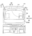
- FIG. 2 is a diagram showing a vehicle equipped with a face orientation estimation system
- FIG. 3 is a diagram showing a form of a wearable device
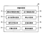
- FIG. 4 is a diagram showing functional blocks constructed in the in-vehicle controller.
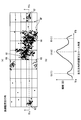
- 5 (a) and 5 (b) are diagrams showing a mode of a two-dimensional distribution of visual recognition points in a straight section and a histogram thereof.
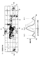
- 6 (a) and 6 (b) are diagrams showing a mode of a two-dimensional distribution of visual recognition points in the left curve section and a histogram thereof.
- FIG. 7 is a diagram illustrating a change in the line-of-sight direction to the yaw direction in a straight section and a threshold value for counting the number of times the left and right side mirrors are viewed.
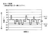
- FIG. 8 is a diagram illustrating a change in the line-of-sight direction to the yaw direction in the left curve section and a threshold value for counting the number of times the left and right side mirrors are viewed.
- FIG. 9 is a flowchart showing each process performed in the in-vehicle control unit.
- FIG. 10 is a diagram comparing the respective false detection and non-detection probabilities when detecting the visual behavior of the left and right side mirrors by the driver.
- FIG. 11 is a block diagram showing the entire face direction estimation system according to the second embodiment.
- the face orientation estimation system 100 includes a wearable device 10 and an in-vehicle device 40 that can communicate with each other, as illustrated in FIGS. 1 and 2.
- the face orientation estimation system 100 mainly functions in the passenger compartment of a vehicle 110 that is a moving object.
- the face direction estimation system 100 detects the behavior of the head HD of a driver DR who gets on the vehicle 110 and drives the vehicle 110 by the wearable device 10.
- the face orientation estimation system 100 uses the in-vehicle device 40 to calculate the face orientation of the driver DR from the detected behavior of the head HD.
- the driver DR's face direction information by the face direction estimation system 100 determines, for example, a decrease in the confirmation frequency for visually recognizing each mirror installed in the vehicle 110, a long look aside, terminal operation in the downward direction, and dozing. Used for applications that When an abnormality of the driver DR as described above is detected, an actuation such as a warning for the driver DR is executed.
- the wearable device 10 is a glasses-type motion sensor device in which the detection circuit 20 is mounted on the glasses 10a as shown in FIG.
- the wearable device 10 shown in FIGS. 1 and 2 is mounted on the head HD of the driver DR and sequentially outputs the face orientation detection results toward the in-vehicle device 40.
- the detection circuit 20 of the wearable device 10 includes a face direction detection unit 11, a communication unit 17, an operation unit 18, a battery 19, and the like.
- the face orientation detection unit 11 is a motion sensor mounted on the glasses 10a (see FIG. 3).
- the face orientation detection unit 11 detects a value related to the face orientation of the driver DR by mounting the wearable device 10 on the head HD of the driver DR.
- the face orientation detection unit 11 includes an electrooculogram sensor 12, a gyro sensor 13, and an acceleration sensor 14.
- the face orientation detection unit 11 sequentially provides the detection results acquired using the sensors 12 to 14 to the communication unit 17.
- the electrooculogram sensor 12 has a plurality of electrodes 12a (see FIG. 3) formed of a metal material such as stainless steel. Each electrode 12a is provided on the frame of the glasses 10a so as to be spaced apart from each other. When the driver DR as a user wears the wearable device 10, each electrode 12 a comes into contact with the skin of the driver DR in the vicinity of the eyeball of the driver DR.
- the electrooculogram sensor 12 measures the electrooculogram that changes with the eye movement of the driver DR based on the potential difference between two points of each electrode 12a. Measurement data (hereinafter referred to as “ocular potential data”) from the electrooculogram sensor 12 is sequentially provided to the communication unit 17 as a detection result.
- the gyro sensor 13 is a sensor that detects angular velocity as a voltage value.
- the gyro sensor 13 measures the magnitude of the angular velocity generated around each of the three axes that are orthogonal to each other defined by the face orientation detection unit 11 when the glasses 10a are attached to the head HD. Based on the angular velocity around each axis, there is an operation of shaking the head HD in the horizontal (yaw) direction, an operation of shaking the head HD in the vertical (pitch) direction, and an operation in the direction of tilting the head HD left and right (roll). Detected. Measurement data (hereinafter referred to as “angular velocity data”) by the gyro sensor 13 is sequentially provided to the communication unit 17 as a detection result.
- the acceleration sensor 14 is a sensor that detects acceleration as a voltage value.
- the acceleration sensor 14 measures the magnitude of acceleration acting on the head HD along the respective axial directions of the three axes defined in the face direction detection unit 11 by being worn on the head HD of the glasses 10a. To do.
- Data measured by the acceleration sensor 14 (hereinafter, “acceleration data”) is sequentially provided to the communication unit 17 as a detection result.
- the communication unit 17 can transmit / receive information to / from the in-vehicle device 40 by wireless communication using, for example, Bluetooth (registered trademark) and a wireless LAN.
- the communication unit 17 has an antenna corresponding to a wireless communication standard.
- the communication unit 17 is electrically connected to the face orientation detection unit 11 and acquires measurement data related to the face orientation output from the sensors 12 to 14.
- the communication unit 17 sequentially encodes each input measurement data and transmits it to the in-vehicle device 40.
- the operation unit 18 includes a power switch for switching the power of the wearable device 10 between an on state and an off state.
- the battery 19 is a power source that supplies power for operation to the face direction detection unit 11 and the communication unit 17.
- the battery 19 may be a primary battery such as a lithium battery or a secondary battery such as a lithium ion battery.
- the in-vehicle device 40 is one of a plurality of electronic control units mounted on the vehicle 110.
- the in-vehicle device 40 operates using electric power supplied from the in-vehicle power source.
- the in-vehicle device 40 is connected with an HMI control unit 50, a vehicle speed sensor 55, a locator 56, and the like.
- the in-vehicle device 40 may be configured so that it can be brought into the vehicle 110 by the driver and fixed to the vehicle body later.
- the HMI (Human Machine Interface) control unit 50 is one of a plurality of electronic control units mounted on the vehicle 110.
- the HMI control unit 50 controls the acquisition of the operation information input by the driver DR and the information presentation to the driver DR in an integrated manner.
- the HMI control unit 50 is connected to, for example, a display 51, a speaker 52, an input device 53, and the like.
- the HMI control unit 50 presents information to the driver DR by controlling the display on the display 51 and the sound output by the speaker 52.
- the vehicle speed sensor 55 is a sensor that measures the traveling speed of the vehicle 110.
- the vehicle speed sensor 55 outputs a vehicle speed pulse corresponding to the traveling speed of the vehicle 110 to the in-vehicle device 40.
- the vehicle speed information calculated based on the vehicle speed pulse may be supplied to the in-vehicle device 40 via an in-vehicle communication bus or the like.
- the locator 56 includes a GNSS receiver 57, a map database 58, and the like.
- a GNSS (Global Navigation Satellite System) receiver 57 receives positioning signals from a plurality of artificial satellites.
- the map database 58 stores map data including road shapes such as road longitudinal gradient and curvature.
- Locator 56 sequentially measures the current position of vehicle 110 based on the positioning signal received by GNSS receiver 57.
- the locator 56 reads out map data around the vehicle 110 and the traveling direction from the map database 58 and sequentially provides it to the in-vehicle device 40. As described above, the in-vehicle device 40 can acquire the shape information of the road on which the vehicle 110 is scheduled to travel.
- the in-vehicle device 40 connected to each of the above components includes a memory 46, a communication unit 47, and an in-vehicle control unit 45.
- the memory 46 is a non-transitional tangible storage medium such as a flash memory.
- the memory 46 stores an application program and the like necessary for the operation of the in-vehicle device 40. Data in the memory 46 can be read and rewritten by the in-vehicle control unit 45.
- the memory 46 may be configured to be built in the in-vehicle device 40, or may be configured to be inserted into a card slot provided in the in-vehicle device 40 in the form of a memory card or the like.
- the memory 46 has a first storage area 46a and a second storage area 46b. In each of the first storage area 46a and the second storage area 46b, data related to the detection result of the face orientation classified by the in-vehicle control unit 45 is accumulated, as will be described later.
- the communication unit 47 transmits and receives information to and from the wearable device 10 by wireless communication.
- the communication unit 47 has an antenna corresponding to a wireless communication standard.
- the communication unit 47 sequentially acquires measurement data from the sensors 12 to 14 by decoding the radio signal received from the communication unit 17.
- the communication unit 47 outputs each acquired measurement data to the in-vehicle control unit 45.
- the in-vehicle control unit 45 is mainly composed of a microcomputer having a processor 45a, a RAM, an input / output interface, and the like.
- the in-vehicle control unit 45 executes the face orientation estimation program stored in the memory 46 by the processor 45a.
- the in-vehicle control unit 45 includes a driver information acquisition unit 71, a travel information acquisition unit 72, a travel section determination unit 73, a stop determination unit 74, a face orientation correction unit 75, a count processing unit 76, an action shown in FIG.
- Functional blocks such as a determination unit 77 and a warning control unit 78 are constructed. The details of each functional block will be described below with reference to FIGS.
- the driver information acquisition unit 71 acquires the detection result by the face direction detection unit 11 received by the communication unit 47 from the communication unit 47. Specifically, the driver information acquisition unit 71 acquires electrooculogram data, angular velocity data, and acceleration data.
- the traveling information acquisition unit 72 sequentially acquires road shape information output from the locator 56. In addition, the travel information acquisition unit 72 acquires the current vehicle speed information of the vehicle 110 based on the vehicle speed pulse output from the vehicle speed sensor 55.
- the travel section determination unit 73 determines whether the vehicle 110 is traveling in a straight section and whether the vehicle 110 is traveling in a horizontal section without inclination. It is determined whether or not. Specifically, when the curvature of the road ahead of the vehicle is smaller than a predetermined threshold, the travel section determination unit 73 determines that the vehicle is traveling in a straight section. On the other hand, when the curvature of the road ahead of the vehicle is larger than the predetermined curvature, the traveling section determination unit 73 determines that the vehicle is traveling in a curved section instead of a straight section.
- the travel section determination unit 73 determines that the vehicle is traveling in a horizontal section.
- the traveling section determination unit 73 determines that the traveling section is traveling on a slope section that is not a horizontal section but an uphill or downhill.
- the stop determination unit 74 determines whether or not the vehicle 110 is in a stopped state. Specifically, the stop determination unit 74 is based on the vehicle speed information acquired by the travel information acquisition unit 72, when the travel speed is substantially zero, or the travel speed is less than a stop threshold (for example, 5 km / h). If it is, it is determined that the vehicle 110 is not in a running state but in a stopped state. On the other hand, when the traveling speed exceeds the above-described stop threshold, the stop determination unit 74 determines that the vehicle 110 is not in a stopped state but in a traveling state.
- a stop threshold for example, 5 km / h
- the stop determination unit 74 can determine whether or not the vehicle 110 is in a traveling state based on acceleration data from the acceleration sensor 14. Specifically, when the vertical vibration associated with traveling is not detected from the transition of the acceleration data and there is substantially no change in the longitudinal acceleration, the stop determination unit 74 indicates that the vehicle 110 is in the stop state. It is determined that
- the face orientation correction unit 75 estimates the line-of-sight direction of the driver DR by combining the electrooculogram data from the electrooculogram sensor 12 and the angular velocity data from the gyro sensor 13. Specifically, the face orientation correcting unit 75 calculates the angle of the head HD in each rotation direction by time-integrating the angular velocity around each axis. As described above, the face orientation correcting unit 75 estimates the face orientation of the driver DR caused by the swing of the driver DR.
- the face orientation correcting unit 75 estimates the eye movement of the driver DR based on the change mode of electrooculogram data using a so-called EOG (Electro-Oculography) method. Specifically, the face orientation correction unit 75 calculates the up / down / left / right directions in which the eyeballs are directed and the amount of change from the front of the eyeballs, based on the front direction of the face of the driver DR. The face direction correction unit 75 specifies the line-of-sight direction of the driver DR with reference to the vehicle 110 by correcting the estimated face direction by the amount of change in the direction of the eyeball.
- EOG Electro-Oculography
- the counting processing unit 76 counts the number of times the driver DR visually recognizes the visual recognition object, the plotting process that plots the line-of-sight direction of the driver DR, the specific process that specifies the position of the visual recognition object mounted on the vehicle 110. At least a counting process to be performed.
- the plot process, the specific process, and the counting process are performed when the stop determination unit 74 determines that the vehicle 110 is not in the stop state, and the stop determination unit 74 determines that the vehicle 110 is in the stop state. In case of failure, it can be interrupted.
- the driver's DR visual point VP (FIG. 5 (a) and FIG. 5 (b) is obtained by sampling the line-of-sight direction of the driver DR specified by the face direction correcting unit 75 at predetermined time intervals. ) See).
- the visual point VP of the driver DR is a geometrical relationship between a virtual curved surface defined to include the interior side surface of the windshield of the vehicle 110 and a virtual line defined to extend in the line-of-sight direction from the eyeball of the driver DR. This is an intersection.
- the virtual curved surface is defined as a shape that smoothly extends the windshield.
- each visual target object includes left and right side mirrors 111 and 112, a rearview mirror 113, a display 51, and a combination meter that are substantially fixed to the vehicle 110.
- the visual recognition object exists in a range where the visual recognition points VP are densely gathered (hereinafter, “aggregation part”).
- the central portion 61 of the windshield center where the most visible points VP gather is a vanishing point in the foreground of the driver DR. Then, each of the collective portions 62 to 66 in which the number of the visually recognized points VP plotted is the second or later becomes the position of each visually recognized object.
- the gathering portion 62 on the left edge of the windshield corresponds to the position of the left side mirror 111 (see FIG. 2).
- the gathering portion 63 on the right edge of the windshield corresponds to the position of the right side mirror 112 (see FIG. 2).
- the collecting unit 64 positioned above the collecting unit 61 corresponds to the position of the rearview mirror 113 (see FIG. 2).
- a set portion 65 located below each set portion 61, 64 corresponds to the position of the display 51 (see FIG. 1).
- the gathering part 66 located in the lower front of the driver DR corresponds to the position of the combination meter.
- 5A, 5B, 6A, and 6B the outermost edge of the horizontally long rectangular frame corresponds to the outer edge of the windshield.
- the position of the vanishing point in the foreground of the driver DR shown in FIG. 2 changes in the left-right direction or the up-down direction with respect to the vehicle 110 in a scene where the vehicle 110 is traveling in a curve section or a slope section.
- the position of the gathering unit 61 is also different in each viewing object during the period in which the vehicle 110 (see FIG. 2) is traveling in a curve section or a slope section. It changes relatively with respect to the other collecting portions 62 to 66 corresponding to the positions of the objects.
- the counting processing unit 76 classifies the position information of the plotted visual recognition points VP based on the road environment in which the vehicle 110 is traveling, and specifies the position of each visual recognition object. Is stored in the first storage area 46a or the second storage area 46b. Specifically, the position information of the visual point VP plotted in the period in which it is determined that the traveling section determination unit 73 is traveling in a horizontal and linear section is accumulated in the first storage area 46a.
- the position information of the visual recognition point VP plotted in the period determined to be traveling in the curve section or the slope section by the travel section determination unit 73 is excluded from the accumulation target in the first storage area 46a. . Then, the position information of the visual recognition point VP plotted in the curve section is associated with the curvature information indicating the magnitude of the curvature of the curve section and the curve direction of the curve, and is stored in the second storage area 46b. Similarly, the position information of the visual recognition point VP plotted in the slope section is associated with slope information indicating the magnitude of the vertical slope of the slope section and the vertical direction of the slope, and is stored in the second storage area 46b.
- the counting process the number of visual recognitions of each visual target by the driver DR is counted.
- the position of the collection target 61 corresponding to the vanishing point is used as a reference (zero point position), based on the transition of the relative change in the line-of-sight direction specified by the face orientation correction unit 75. The number of viewing times is counted (see FIGS. 7 and 8).
- a threshold is set for counting that each visual target object has been viewed.
- the threshold values in the vertical direction and the horizontal direction can be individually set for one visual object.
- the count processing unit 76 counts the number of times that the line-of-sight direction specified by the face orientation correcting unit 75 exceeds each threshold as the number of times of viewing each visual target object.
- a threshold th (r) in the right direction from a zero point position based on the position of the gathering unit 61 (see FIGS. 5A and 5B).
- the counting processing unit 76 counts that the right side mirror 112 (see FIG. 2) is viewed once.
- the line-of-sight direction exceeds the threshold th (l) (for example, 30 °) to the left from the zero point position based on the position of the gathering unit 61 (see FIGS. 5A and 5B).
- the counting process part 76 counts that the right side mirror 112 (refer FIG.
- the behavior determination unit 77 determines whether the visual recognition behavior of the driver DR who visually recognizes each visual target object has changed. As described above, in a scene where the vehicle 110 travels in a curve section or a slope section, the position of the vanishing point changes in the foreground visually recognized by the driver DR (see FIGS. 6A and 6B). ). The behavior determination unit 77 detects the occurrence of a change in the viewing behavior of the driver DR caused by the position change of the vanishing point.
- the behavior determination unit 77 can determine whether or not the visual behavior of the driver DR has changed based on the change in the detection result of the face direction detection unit 11. Specifically, the behavior determination unit 77 determines whether the viewing behavior of the driver DR has changed based on the behavior change of the behavior of visually recognizing the side mirror far from the driver DR, that is, the left side mirror 111. Determine whether or not. The behavior determination unit 77 determines whether or not the visual behavior of the driver DR has changed based on the frequency of viewing the left side mirror 111 (number of times per predetermined time) and the change in the pattern of viewing the left side mirror 111. Can be determined.
- the behavior determination unit 77 can detect a change in the visual behavior of the driver DR based on the determination result of the travel section determination unit 73. Specifically, the behavior determination unit 77 determines that the visual behavior of the driver DR has changed when the travel segment determination unit 73 determines that the vehicle travels in a curve section or a slope section. The determination result by the above action determination unit 77 is sequentially provided to the count processing unit 76.
- the counting processing unit 76 changes the content of the counting process so as to correspond to the position change of the vanishing point. Specifically, the counting processing unit 76, when the behavior determining unit 77 determines that the driver DR's visual behavior has changed, the aggregation unit 61 (see FIGS. 6A and 6B). Change the reference zero point position according to the slide position. As a result, as shown in FIGS. 5A to 8, each threshold value used for counting the number of times of visual recognition is changed.
- the collecting unit 61 shifts to the left side with respect to the vehicle 110, and the left side mirror It is close to the gathering portion 62 corresponding to 111 (see FIG. 2).
- the zero point position serving as the reference for the swing angle is also shifted to the left. Therefore, as shown in FIG. 8, the absolute value of the threshold th (r) for counting the number of times the right side mirror 112 is viewed is changed to a larger value (for example, 25 °) than when traveling in a straight section.
- the absolute value of the threshold th (l) for counting the number of times the left side mirror 111 is visually recognized is changed to a smaller value (for example, 20 °) than when traveling in a straight section.
- Specific values of the threshold values th (r) and th (l) are distributions of accumulated data corresponding to the road environment currently being traveled among the positional information of the visual recognition points VP accumulated in the second storage area 46b. Is set based on Therefore, the threshold values th (r) and th (l) change stepwise according to the curvature of the curve and the gradient.
- the warning control unit 78 acquires, from the counting processing unit 76, the number of times of viewing of each visual target object per predetermined time counted in the counting process.
- the warning control unit 78 determines whether or not the driver DR's visual behavior is in an abnormal state based on the obtained number of times of visual recognition of each visual target object. For example, when the frequency of visually recognizing the left and right side mirrors 111 and 112 falls below a predetermined frequency threshold, the warning control unit 78 determines that the state is abnormal.
- the warning control unit 78 outputs a command signal instructing execution of warning to the HMI control unit 50.
- a warning for the driver DR is performed by the display 51, the speaker 52, and the like.
- each process for estimating the face direction by the in-vehicle controller 45 described above will be described with reference to FIGS. 1 and 2 based on the flowchart of FIG.
- Each process shown in FIG. 9 is based on the fact that, for example, both the wearable device 10 and the in-vehicle device 40 are powered on, and transmission of the detection result from the wearable device 10 to the in-vehicle device 40 is started. Started by.
- Each process illustrated in FIG. 9 is repeatedly performed until at least one of the wearable device 10 and the in-vehicle device 40 is turned off.
- each threshold value for counting the number of times each visual object is viewed is set, the number of times the visual object is viewed is started, and the process proceeds to S103.
- a preset initial value is set as each threshold value.
- the traveling environment of the vehicle 110 is determined based on the distribution of the visual recognition points VP that started plotting in S101, the road shape information, the latest vehicle speed information, and the like, and the process proceeds to S104. If it is determined in S103 that the vehicle 110 is in a stopped state, the process returns from S104 to S103. Thus, when it is determined that the vehicle 110 is in the stopped state, the plot processing started in S101 may be temporarily interrupted until the vehicle 110 is switched to the traveling state. On the other hand, when it is determined in S103 that the vehicle 110 is in the traveling state, the process proceeds from S104 to S105.
- S105 it is determined whether the visual behavior has changed. If the determination result of the traveling environment is substantially the same as the conventional one in S103, it is determined in S105 that the visual behavior has not changed, and the process proceeds to S107. On the other hand, if a change in the determination result of the driving environment has occurred in S103, it is determined in S105 that the visual behavior has changed, and the process proceeds to S106.
- the threshold value corresponding to the traveling environment determined in the immediately preceding S103 is changed, and the process proceeds to S107.
- a counting process is performed to count the number of times each visual target is viewed using the currently set threshold values, and the process proceeds to S108.
- the identification of the line-of-sight direction of the driver DR and the plotting of the visual recognition point VP are continued, and the data of the plotted visual recognition point VP is accumulated in the respective storage areas 46a and 46b corresponding to the current driving environment, and in S109. move on.
- S109 it is determined whether or not the driver DR is in an abnormal state based on the result of the counting process performed in the immediately preceding S107.
- the process returns to S103.
- operator DR being in an abnormal state in S109, it progresses to S110.
- a command signal for instructing the HMI control unit 50 to execute a warning is output, and the series of processes is temporarily terminated. Based on the command signal output in S110, a warning by the display 51 and the speaker 52 is performed. When the warning in S110 ends, the vehicle-mounted control unit 45 starts S101 again.
- the driver DR when the vehicle 110 travels in a curve section, a slope section, or the like, and a change occurs in the position of the vanishing point in the foreground, the driver DR It is determined that the viewing behavior has changed. As a result, the counting process for counting the number of times that the driver DR visually recognizes the visual recognition object is changed to the content corresponding to the change in the visual recognition behavior of the driver DR in accordance with the position change of the vanishing point. Therefore, even if the driver DR's visual behavior changes due to the position change of the vanishing point, the number of times the driver visually recognizes the visual target object can be accurately counted.
- the detection result of the driver DR's face orientation surely changes.
- a clear change may occur in the visual recognition frequency of the visual object and the visual pattern of the visual object based on the detection result of the face orientation. Therefore, if it is determined whether or not there is a change in the viewing behavior of the driver DR based on the changes in the viewing frequency and the viewing pattern, the occurrence of the change in the viewing behavior due to the position change of the vanishing point can be detected without omission. Become.
- whether or not there is a change in the entire visual behavior due to the change in the position of the vanishing point is determined based on the behavior change of the behavior of visually recognizing the left side mirror 111 far from the driver DR. .
- the behavior change of the behavior of visually recognizing the left side mirror 111 far from the driver DR. For example, when visually recognizing the right side mirror 112, it is possible to move only by eye movement mainly by eye movement, so that the change in face orientation due to swinging becomes small.
- the amount of movement is insufficient only by the movement of the line of sight by eye movement, and thus a clear change in the face orientation due to swinging occurs.
- the behavior determination unit 77 can accurately determine the occurrence of the change in the behavior of the driver DR as a whole.
- the behavior determination unit 77 of the first embodiment can also determine the change in the visual behavior of the driver DR by using the determination result of the travel section determination unit 73.
- the vanishing point position change mainly occurs in the curve section and the slope section. Therefore, if the road shape information is used to specify the traveling of the curve section or the slope section, the behavior determination unit 77 accurately determines the occurrence of the change in the visual behavior due to the position change of the vanishing point without delay. be able to.
- the position information of the visual recognition point VP on which the face orientation detection result is plotted is accumulated in the first storage area 46a and used for specifying the position of the visual recognition object.
- the position information of the visual recognition point VP is continuously accumulated, the position of the visual recognition object can be specified with higher accuracy. As a result, it is possible to improve both the accuracy of determining the behavior change of the visual recognition behavior and the accuracy of counting the number of times the visual target is viewed.
- the position information of the visual recognition point VP acquired during the period determined by the traveling section determination unit 73 as not being a straight section is not accumulated in the first storage area 46a. According to such processing, only the position information of the visual recognition point VP in the period in which the position change of the vanishing point has not substantially occurred is accumulated in the first storage area 46a. Therefore, based on the position information accumulated in the first storage area 46a, the position of the visual recognition object can be specified more accurately in the straight section.
- each threshold used for counting the number of visual recognitions is changed.
- the counting processing unit 76 can select an appropriate threshold value in accordance with the change in the visual recognition behavior of the driver DR, and can continue to count the number of visual recognitions of the visual target object with high accuracy.
- the counting process is interrupted when the vehicle 110 is substantially in a stopped state.
- the warning to the driver DR related to the visual recognition behavior is troublesome for the driver DR and is substantially unnecessary. Therefore, if it is a stop state, it is desirable that the counting process is interrupted when the warning is interrupted.
- the acceleration data detected by the acceleration sensor 14 of the face direction detection unit 11 is used for the stop determination of the stop determination unit 74.
- the existing configuration for detecting the behavior of the head HD is used, it is possible to accurately determine the stop state while avoiding the complexity of the face direction estimation system 100.
- the face direction of the driver DR is estimated based on the measurement data of the gyro sensor 13 attached to the head HD of the driver DR.
- the gyro sensor 13 that moves integrally with the head HD can faithfully detect the movement of the head HD.
- the estimated accuracy of the face direction of the driver DR is easily ensured.
- the face direction detection unit 11 if the face direction detection unit 11 is mounted on the glasses 10a, the face direction detection unit 11 is not easily displaced from the head HD, and the movement of the head HD is surely performed. It can be detected. Therefore, the form in which the face direction detection unit 11 is mounted on the glasses 10a can contribute to an improvement in the accuracy of the process of counting the number of times the visual target is viewed.
- the first storage area 46a corresponds to the “storage area”
- the driver information acquisition unit 71 corresponds to the “face direction information acquisition unit”
- the in-vehicle device 40 corresponds to the “face direction estimation device”.
- the vehicle 110 corresponds to a “moving object”.
- a face orientation estimation system 200 according to the second embodiment of the present disclosure shown in FIG. 11 is a modification of the first embodiment.
- each process for estimating the face orientation of the driver DR (see FIG. 2) is mainly performed by the wearable device 210.
- the in-vehicle device 240 transmits the acquired vehicle speed information and road shape information from the communication unit 47 to the wearable device 210 by wireless communication.
- Wearable device 210 is a glasses-type motion sensor device similar to that of the first embodiment (see FIG. 3).
- the detection circuit 220 of the wearable device 210 includes a wearable control unit 215 and a vibration notification unit 218 in addition to the face orientation detection unit 11, the communication unit 17, the operation unit 18, and the battery 19 that are substantially the same as those in the first embodiment. Yes.
- the wearable control unit 215 includes a processor 215a, a RAM, a microcomputer mainly including an input / output interface, a memory 216, and the like.
- a processor 215a a RAM
- a microcomputer mainly including an input / output interface
- a memory 216 and the like.
- a first storage area 216a and a second storage area 216b corresponding to the storage areas 46a and 46b (see FIG. 1) of the first embodiment are secured.
- the wearable control unit 215 executes the face orientation estimation program stored in the memory 216 by the processor 215a, similarly to the in-vehicle control unit 45 (see FIG. 1) of the first embodiment.
- a plurality of functional blocks substantially the same as those of the first embodiment are constructed in the wearable control unit 215.
- the driver information acquisition unit 71 (see FIG. 4) constructed in the wearable control unit 215 can acquire the detection result directly from the face orientation detection unit 11.
- the travel information acquisition unit 72 (see FIG. 4) constructed in the wearable control unit 215 acquires vehicle speed information and road shape information received by the communication unit 17.
- the warning control unit 78 (see FIG. 4) constructed in the wearable control unit 215 outputs a command signal for commanding the warning to the vibration notification unit 218 when it is determined that the state is abnormal. As a result, a warning for the driver DR (see FIG. 2) is performed by the vibration of the vibration notification unit 218.
- the counting process can be changed to a content corresponding to a change in the driver's DR visual behavior. . Therefore, similarly to the first embodiment, even if the driver DR's visual behavior changes due to the position change of the first vanishing point, the number of times the driver visually recognized the visual target can be accurately counted. Become.
- the wearable device 210 corresponds to a “face orientation estimating device”.
- each process related to face orientation estimation is performed by either an in-vehicle device or a wearable device.
- each process related to face orientation estimation may be performed in a distributed manner by each processor of the in-vehicle device and the wearable device.
- the face orientation estimation system corresponds to a “face orientation estimation device”.
- each function provided by the processor in the above embodiment can be provided by hardware and software different from the above-described configuration, or a combination thereof.
- the in-vehicle device may be, for example, a mobile terminal such as a smartphone and a tablet brought into the vehicle by the driver.
- the wearable device 210 acquires vehicle speed information and road shape information by wireless communication.
- the wearable device may perform each process related to face orientation estimation without using the vehicle speed information and the road shape information.
- the in-vehicle device of the first embodiment can acquire the planned travel route of the vehicle from the navigation device, for example, even in a scene where a right / left turn is performed, the travel section determination unit is a straight section as in the determination of the curve section. It is possible to determine that it is not. In such a form, it is possible to accurately warn of an oversight of the side mirror in a scene where a right or left turn is performed.
- the face orientation detection unit of the above embodiment has a plurality of sensors 12-14.
- the electrooculogram sensor can be omitted from the face orientation detection unit as long as it does not take into account changes in the line-of-sight direction due to eye movements.
- the acceleration sensor can be omitted from the face direction detection unit.
- other sensors different from the above for example, a magnetic sensor and a temperature sensor, may be included in the face orientation detection unit.
- the glasses-type configuration is exemplified as the wearable device.
- the wearable device is not limited to the glasses-type configuration as long as it can be attached to the head above the neck.
- a badge-type wearable device attached to a hat or the like, or an ear-mounted wearable device that is hooked behind the ear can be employed in the face orientation estimation system.
- the configuration for detecting the driver's face orientation is not limited to the wearable device.
- a camera for photographing the driver's face may be provided in the face direction estimation system as a face direction detection unit.
- the in-vehicle control unit performs a process of detecting the face orientation by image analysis from the image captured by the camera.
- the behavior determination unit of the above embodiment determines the change in the driver's visual behavior by detecting the change in the visual frequency and the visual pattern of the left side mirror.
- the behavior determination unit may determine that the driver's visual behavior has changed, for example, when the ratio of the number of times of visual recognition of the side mirrors arranged side by side changes within a predetermined period.
- the behavior determination unit detects a change in the viewing frequency and the viewing pattern of the right side mirror as a side mirror far from the driver, thereby driving It is desirable to determine a change in a person's visual behavior.
- the position of the display, the meter, etc. is specified as the visual recognition object, but the visual recognition object whose position is specified may be only the left and right side mirrors and the rearview mirror. Moreover, the position of the configuration of another vehicle may be specified as the visual recognition object. Furthermore, instead of the left and right side mirrors, the position of the screen of the electronic mirror may be specified as the visual recognition object.
- the warning based on the abnormality determination and each processing by the counting processing unit are interrupted.
- the process of plotting the driver's line-of-sight direction may be continued even when the vehicle is stopped.
- stop determination may be performed based on the transition of the positioning signal received by the locator.
- the position information of the visual recognition point VP acquired by the plot processing is classified and accumulated in the first storage area and the second storage area.
- the classification and accumulation of position information may not be performed.
- the storage medium in which the first storage area and the second storage area are provided is not limited to the flash memory, and may be another storage medium such as a hard disk drive.
- each threshold when counting the number of visual recognitions is also set based on the position of the collective part corresponding to the vanishing point.
- each threshold value may be set based on the specific position of the windshield.
- the process to which the face direction estimation method of the present disclosure is applied can be performed even on a mobile object different from the above embodiment. Furthermore, an operator who monitors an automatic driving function in a vehicle during automatic driving can also correspond to a driver.
- each section is expressed as S101, for example.
- each section can be divided into a plurality of subsections, while a plurality of sections can be combined into one section.
- each section configured in this manner can be referred to as a device, module, or means.
Abstract
Provided is a face orientation estimation device, comprising: a face orientation information acquisition unit (71) which acquires a detection result in which the face orientation of a driver (DR) of a mobile body (110) has been detected; a count processing unit (76) which, on the basis of the detection result, counts the number of times that the driver has viewed objects to be viewed which are installed upon the mobile body; and an action assessment unit (77) which assesses whether a viewing action of the driver who views the objects to be viewed has changed due to a change in the position of a vanishing point in the foreground which the driver views. If the viewing action of the driver has changed, the count processing unit changes the description of the count process in accordance with the change in the position of the vanishing point.
Description
本出願は、2016年5月20日に出願された日本特許出願番号2016-101244号に基づくもので、ここにその記載内容を援用する。
This application is based on Japanese Patent Application No. 2016-101244 filed on May 20, 2016, the contents of which are incorporated herein by reference.
本開示は、車両等を運転する運転者の顔向きを推定する顔向き推定装置及び顔向き推定方法に関するものである。
The present disclosure relates to a face direction estimation device and a face direction estimation method for estimating the face direction of a driver who drives a vehicle or the like.
従来、例えば特許文献1には、車両等の移動体を運転する運転者の顔をカメラによって撮影し、撮影画像に基づいて運転者の顔向きを認識する技術が開示されている。具体的に、特許文献1の注意力低下検出システムは、認識された顔向きに基づき、車両に設置されたサイドミラーを運転者が視認した視認回数を計数する。そして、計数されたサイドミラーの視認回数に基づき、運転者の注意力の低下が判定される。
Conventionally, for example, Patent Document 1 discloses a technique in which a driver's face driving a moving body such as a vehicle is photographed by a camera and the driver's face orientation is recognized based on the photographed image. Specifically, the attention reduction detection system of Patent Document 1 counts the number of times the driver visually recognizes the side mirror installed in the vehicle based on the recognized face orientation. Then, based on the counted number of times the side mirror is visually recognized, a decrease in the driver's attention is determined.
さて、運転者がサイドミラーを視認しているときの顔向きは、運転者の体格、着座位置、及び着座姿勢等に起因して異なってくる。そこで本開示の発明者らは、視認対象物の位置を運転者の視認行動から特定し、特定した視認対象物の位置と、認識された運転者の顔向きとを比較することにより、運転者による視認対象物の視認回数を計数する技術について、開発を進めてきた。
Now, the face orientation when the driver is viewing the side mirror differs depending on the driver's physique, sitting position, sitting posture, and the like. Therefore, the inventors of the present disclosure specify the position of the visual recognition object from the visual behavior of the driver, and compare the position of the visual recognition object thus identified with the recognized driver's face direction. We have been developing a technology that counts the number of times a visual target is viewed.
しかし、視認対象物の位置を運転者の視認行動から特定する技術では、カーブ及び坂道等の道路環境に起因して、視認回数を計数する精度が低下するという課題を、本開示の発明者らは新たに発見した。詳しく説明すると、運転者は通常、前景中の消失点をゼロ点位置として、この消失点から視認対象物へと顔向きを変化させている。故に、カーブ及び坂道等を走行しているとき、前景中の消失点の位置変化が生じると、消失点から視認対象物へ顔向きを変化させる視認行動の態様も変化してしまう。そのため、消失点の位置変化に起因して運転者の視認行動が変化してしまうと、運転者による視認対象物の視認回数が正しく計数されなくなり得た。
However, with the technology for identifying the position of the visual recognition object from the visual behavior of the driver, the inventors of the present disclosure have a problem that the accuracy of counting the number of visual recognitions is reduced due to road environments such as curves and slopes. Newly discovered. More specifically, the driver usually changes the face direction from the vanishing point to the visual recognition object with the vanishing point in the foreground as the zero point position. Therefore, when traveling on a curve, a slope, or the like, if the position of the vanishing point in the foreground changes, the mode of visual behavior that changes the face direction from the vanishing point to the visual target object also changes. For this reason, if the driver's visual behavior changes due to the position change of the vanishing point, the number of times the driver visually recognizes the visual target object may not be counted correctly.
本開示は、消失点の位置変化に起因して運転者の視認行動が変化しても、運転者が視認対象物を視認した回数を精度良く計数することが可能な顔向き推定装置及び顔向き推定方法を提供することを目的とする。
The present disclosure relates to a face direction estimation device and a face direction that can accurately count the number of times a driver visually recognizes a visual target object even if the driver's visual behavior changes due to a change in the position of the vanishing point. An object is to provide an estimation method.
本開示の第一の態様において、顔向き推定装置は、移動体を運転する運転者の顔向きを検出した検出結果を取得する顔向き情報取得部と、前記顔向き情報取得部の取得した前記検出結果に基づき、前記移動体に設置された視認対象物を前記運転者が視認した回数を計数する計数処理部と、前記運転者の視認する前景中での消失点の位置変化に起因して前記視認対象物を視認する前記運転者の視認行動が変化したか否かを判定する行動判定部と、を備える。前記計数処理部は、前記行動判定部にて前記運転者の視認行動が変化したと判定された場合に、前記消失点の位置変化に合わせて計数処理の内容を変更する。
In the first aspect of the present disclosure, the face direction estimation device includes a face direction information acquisition unit that acquires a detection result of detecting a face direction of a driver who drives a moving body, and the face direction information acquisition unit Based on the detection result, the counting processing unit that counts the number of times the driver visually recognizes the visual target object installed on the moving body, and due to the position change of the vanishing point in the foreground visually recognized by the driver An action determination unit that determines whether or not the driver's visual action for visually recognizing the visual target object has changed. When the behavior determination unit determines that the driver's visual behavior has changed, the counting processing unit changes the content of the counting process in accordance with the position change of the vanishing point.
上記の顔向き推定装置によれば、移動体がカーブ等を走行することにより、前景中での消失点の位置変化が生じると、こうした位置変化に起因して運転者の視認行動が変化したと判定され得る。その結果、移動体に設置された視認対象物を運転者が視認した回数を計数する処理は、消失点の位置変化に合わせて、運転者の視認行動の変化に対応した内容に変更される。したがって、消失点の位置変化に起因して運転者の視認行動が変化しても、運転者が視認対象物を視認した回数は、精度良く計数可能となる。
According to the above face orientation estimation device, when the moving body travels on a curve or the like, and the position change of the vanishing point in the foreground occurs, the driver's visual behavior changes due to such a position change. Can be determined. As a result, the process of counting the number of times the driver visually recognizes the visual target object installed on the moving body is changed to the content corresponding to the change in the driver's visual behavior in accordance with the change in the position of the vanishing point. Therefore, even if the driver's visual behavior changes due to the position change of the vanishing point, the number of times that the driver visually recognizes the visual target object can be accurately counted.
本開示の第二の態様において、移動体を運転する運転者の顔向きを推定する顔向き推定方法であって、少なくとも一つのプロセッサは、前記運転者の顔向きを検出する顔向き検出部の検出結果に基づき、前記移動体に設置された視認対象物を前記運転者が視認した回数を計数し、前記運転者の視認する前景中での消失点の位置変化に起因して前記視認対象物を視認する前記運転者の視認行動が変化したか否かを判定し、前記運転者の視認行動が変化したと判定された場合に、前記消失点の位置変化に合わせて計数処理の内容を変更する。
According to a second aspect of the present disclosure, there is provided a face direction estimation method for estimating a face direction of a driver who drives a moving body, wherein at least one processor includes a face direction detection unit that detects the face direction of the driver. Based on the detection result, the driver counts the number of times the driver visually recognizes the visually recognized object installed on the moving body, and the visually recognized object is caused by a change in the position of the vanishing point in the foreground visually recognized by the driver. It is determined whether or not the driver's visual behavior has changed, and when it is determined that the driver's visual behavior has changed, the content of the counting process is changed in accordance with the position change of the vanishing point. To do.
上記の顔向き推定方法によれば、移動体がカーブ等を走行することにより、前景中での消失点の位置変化が生じると、こうした位置変化に起因して運転者の視認行動が変化したと判定され得る。その結果、移動体に設置された視認対象物を運転者が視認した回数を計数する処理は、消失点の位置変化に合わせて、運転者の視認行動の変化に対応した内容に変更される。したがって、消失点の位置変化に起因して運転者の視認行動が変化しても、運転者が視認対象物を視認した回数は、精度良く計数可能となる。
According to the face direction estimation method described above, when the position of the vanishing point in the foreground occurs due to the moving body traveling on a curve or the like, the driver's visual behavior changes due to such a position change. Can be determined. As a result, the process of counting the number of times the driver visually recognizes the visual target object installed on the moving body is changed to the content corresponding to the change in the driver's visual behavior in accordance with the change in the position of the vanishing point. Therefore, even if the driver's visual behavior changes due to the position change of the vanishing point, the number of times that the driver visually recognizes the visual target object can be accurately counted.
本開示についての上記目的およびその他の目的、特徴や利点は、添付の図面を参照しながら下記の詳細な記述により、より明確になる。その図面は、
図1は、第一実施形態による顔向き推定システムの全体を示すブロック図であり、
図2は、顔向き推定システムを搭載した車両を示す図であり、
図3は、ウェアラブルデバイスの形態を示す図であり、
図4は、車載制御部に構築される機能ブロックを示す図であり、
図5(a)および図5(b)は、直線区間における視認点の二次元分布の態様と、そのヒストグラムとを示す図であり、
図6(a)および図6(b)は、左カーブ区間における視認点の二次元分布の態様と、そのヒストグラムとを示す図であり、
図7は、直線区間におけるヨー方向への視線方向の変化の推移と、左右のサイドミラーの視認回数を計数する閾値とを示す図であり、
図8は、左カーブ区間におけるヨー方向への視線方向の変化の推移と、左右のサイドミラーの視認回数を計数する閾値とを示す図であり、
図9は、車載制御部にて実施される各処理を示すフローチャートであり、
図10は、運転者による左右のサイドミラーの視認行動を検出した場合に、それぞれの誤検出及び未検出の各確率を比較して示す図であり、
図11は、第二実施形態による顔向き推定システムの全体を示すブロック図である。
The above and other objects, features and advantages of the present disclosure will become more apparent from the following detailed description with reference to the accompanying drawings. The drawing
FIG. 1 is a block diagram showing the entire face direction estimation system according to the first embodiment. FIG. 2 is a diagram showing a vehicle equipped with a face orientation estimation system, FIG. 3 is a diagram showing a form of a wearable device, FIG. 4 is a diagram showing functional blocks constructed in the in-vehicle controller. 5 (a) and 5 (b) are diagrams showing a mode of a two-dimensional distribution of visual recognition points in a straight section and a histogram thereof. 6 (a) and 6 (b) are diagrams showing a mode of a two-dimensional distribution of visual recognition points in the left curve section and a histogram thereof. FIG. 7 is a diagram illustrating a change in the line-of-sight direction to the yaw direction in a straight section and a threshold value for counting the number of times the left and right side mirrors are viewed. FIG. 8 is a diagram illustrating a change in the line-of-sight direction to the yaw direction in the left curve section and a threshold value for counting the number of times the left and right side mirrors are viewed FIG. 9 is a flowchart showing each process performed in the in-vehicle control unit. FIG. 10 is a diagram comparing the respective false detection and non-detection probabilities when detecting the visual behavior of the left and right side mirrors by the driver. FIG. 11 is a block diagram showing the entire face direction estimation system according to the second embodiment.
以下、本開示の複数の実施形態を図面に基づいて説明する。尚、各実施形態において対応する構成要素には同一の符号を付すことにより、重複する説明を省略する場合がある。各実施形態において構成の一部分のみを説明している場合、当該構成の他の部分については、先行して説明した他の実施形態の構成を適用することができる。また、各実施形態の説明において明示している構成の組み合わせばかりではなく、特に組み合わせに支障が生じなければ、明示していなくても複数の実施形態の構成同士を部分的に組み合わせることができる。そして、複数の実施形態及び変形例に記述された構成同士の明示されていない組み合わせも、以下の説明によって開示されているものとする。
Hereinafter, a plurality of embodiments of the present disclosure will be described with reference to the drawings. In addition, the overlapping description may be abbreviate | omitted by attaching | subjecting the same code | symbol to the corresponding component in each embodiment. When only a part of the configuration is described in each embodiment, the configuration of the other embodiment described above can be applied to the other part of the configuration. Moreover, not only the combination of the configurations explicitly described in the description of each embodiment, but also the configuration of a plurality of embodiments can be partially combined even if they are not explicitly described, as long as there is no problem in the combination. And the combination where the structure described in several embodiment and the modification is not specified shall also be disclosed by the following description.
(第一実施形態)
本開示の第一実施形態による顔向き推定システム100は、図1及び図2に示すように、互いに通信可能なウェアラブルデバイス10及び車載デバイス40等によって構成されている。顔向き推定システム100は、移動体である車両110の車室内において主に機能する。顔向き推定システム100は、車両110に搭乗し、車両110を運転する運転者DRの頭部HDの挙動を、ウェアラブルデバイス10によって検出する。顔向き推定システム100は、検出された頭部HDの挙動から運転者DRの顔向きを車載デバイス40によって演算する。 (First embodiment)
The faceorientation estimation system 100 according to the first embodiment of the present disclosure includes a wearable device 10 and an in-vehicle device 40 that can communicate with each other, as illustrated in FIGS. 1 and 2. The face orientation estimation system 100 mainly functions in the passenger compartment of a vehicle 110 that is a moving object. The face direction estimation system 100 detects the behavior of the head HD of a driver DR who gets on the vehicle 110 and drives the vehicle 110 by the wearable device 10. The face orientation estimation system 100 uses the in-vehicle device 40 to calculate the face orientation of the driver DR from the detected behavior of the head HD.
本開示の第一実施形態による顔向き推定システム100は、図1及び図2に示すように、互いに通信可能なウェアラブルデバイス10及び車載デバイス40等によって構成されている。顔向き推定システム100は、移動体である車両110の車室内において主に機能する。顔向き推定システム100は、車両110に搭乗し、車両110を運転する運転者DRの頭部HDの挙動を、ウェアラブルデバイス10によって検出する。顔向き推定システム100は、検出された頭部HDの挙動から運転者DRの顔向きを車載デバイス40によって演算する。 (First embodiment)
The face
顔向き推定システム100による運転者DRの顔向き情報は、例えば車両110に設置された各ミラー等を視認する確認頻度の低下、長時間の脇見、下向きでの端末の操作、及び居眠り等を判定するアプリケーションに用いられる。以上のような運転者DRの異常が検出されると、運転者DRに対する警告等のアクチュエーションが実行される。
The driver DR's face direction information by the face direction estimation system 100 determines, for example, a decrease in the confirmation frequency for visually recognizing each mirror installed in the vehicle 110, a long look aside, terminal operation in the downward direction, and dozing. Used for applications that When an abnormality of the driver DR as described above is detected, an actuation such as a warning for the driver DR is executed.
ウェアラブルデバイス10は、図3に示すように、検出回路20をメガネ10aに搭載させたメガネ型のモーションセンサデバイスである。図1及び図2に示すウェアラブルデバイス10は、運転者DRの頭部HDに装着され、顔向きの検出結果を車載デバイス40へ向けて逐次出力する。ウェアラブルデバイス10の検出回路20は、顔向き検出部11、通信ユニット17、操作部18、及びバッテリ19等によって構成されている。
The wearable device 10 is a glasses-type motion sensor device in which the detection circuit 20 is mounted on the glasses 10a as shown in FIG. The wearable device 10 shown in FIGS. 1 and 2 is mounted on the head HD of the driver DR and sequentially outputs the face orientation detection results toward the in-vehicle device 40. The detection circuit 20 of the wearable device 10 includes a face direction detection unit 11, a communication unit 17, an operation unit 18, a battery 19, and the like.
顔向き検出部11は、メガネ10a(図3参照)に搭載されたモーションセンサである。顔向き検出部11は、ウェアラブルデバイス10が運転者DRの頭部HDに装着されることで、運転者DRの顔向きに関連した値の検出を行う。顔向き検出部11は、眼電位センサ12、ジャイロセンサ13、及び加速度センサ14を有している。顔向き検出部11は、各センサ12~14を用いて取得した検出結果を、通信ユニット17に逐次提供する。
The face orientation detection unit 11 is a motion sensor mounted on the glasses 10a (see FIG. 3). The face orientation detection unit 11 detects a value related to the face orientation of the driver DR by mounting the wearable device 10 on the head HD of the driver DR. The face orientation detection unit 11 includes an electrooculogram sensor 12, a gyro sensor 13, and an acceleration sensor 14. The face orientation detection unit 11 sequentially provides the detection results acquired using the sensors 12 to 14 to the communication unit 17.
眼電位センサ12は、例えばステンレス等の金属材料によって形成された複数の電極12a(図3参照)を有している。各電極12aは、互いに離間した配置にてメガネ10aのフレームに設けられている。ユーザである運転者DRがウェアラブルデバイス10を装着することにより、各電極12aは、運転者DRの眼球付近にて、運転者DRの皮膚に接触する。眼電位センサ12は、運転者DRの眼球運動に伴って変化する眼電位を、各電極12aのうちの二点間の電位差に基づいて計測する。眼電位センサ12による計測データ(以下、「眼電位データ」)は、検出結果として通信ユニット17に逐次提供される。
The electrooculogram sensor 12 has a plurality of electrodes 12a (see FIG. 3) formed of a metal material such as stainless steel. Each electrode 12a is provided on the frame of the glasses 10a so as to be spaced apart from each other. When the driver DR as a user wears the wearable device 10, each electrode 12 a comes into contact with the skin of the driver DR in the vicinity of the eyeball of the driver DR. The electrooculogram sensor 12 measures the electrooculogram that changes with the eye movement of the driver DR based on the potential difference between two points of each electrode 12a. Measurement data (hereinafter referred to as “ocular potential data”) from the electrooculogram sensor 12 is sequentially provided to the communication unit 17 as a detection result.
ジャイロセンサ13は、角速度を電圧値として検出するセンサである。ジャイロセンサ13は、メガネ10aの頭部HDへの装着により、顔向き検出部11において規定された互いに直交する三軸について、各軸周りに生じる角速度の大きさを計測する。各軸周りの角速度に基づき、横(ヨー)方向に頭部HDを振る動作、縦(ピッチ)方向に頭部HDを振る動作、及び頭部HDを左右に傾ける(ロール)方向の動作等が検出される。ジャイロセンサ13による計測データ(以下、「角速度データ」)は、検出結果として通信ユニット17に逐次提供される。
The gyro sensor 13 is a sensor that detects angular velocity as a voltage value. The gyro sensor 13 measures the magnitude of the angular velocity generated around each of the three axes that are orthogonal to each other defined by the face orientation detection unit 11 when the glasses 10a are attached to the head HD. Based on the angular velocity around each axis, there is an operation of shaking the head HD in the horizontal (yaw) direction, an operation of shaking the head HD in the vertical (pitch) direction, and an operation in the direction of tilting the head HD left and right (roll). Detected. Measurement data (hereinafter referred to as “angular velocity data”) by the gyro sensor 13 is sequentially provided to the communication unit 17 as a detection result.
加速度センサ14は、加速度を電圧値として検出するセンサである。加速度センサ14は、メガネ10aの頭部HDへの装着により、顔向き検出部11において規定された互いに直交する三軸について、それぞれの軸方向に沿って頭部HDに作用する加速度大きさを計測する。加速度センサ14による計測データ(以下、「加速度データ」)は、検出結果として通信ユニット17に逐次提供される。
The acceleration sensor 14 is a sensor that detects acceleration as a voltage value. The acceleration sensor 14 measures the magnitude of acceleration acting on the head HD along the respective axial directions of the three axes defined in the face direction detection unit 11 by being worn on the head HD of the glasses 10a. To do. Data measured by the acceleration sensor 14 (hereinafter, “acceleration data”) is sequentially provided to the communication unit 17 as a detection result.
通信ユニット17は、車載デバイス40との間において、例えばブルートゥース(登録商標)及び無線LAN等による無線通信によって情報の送受信を行うことができる。通信ユニット17は、無線通信の規格に対応したアンテナを有している。通信ユニット17は、顔向き検出部11と電気的に接続されており、各センサ12~14から出力された顔向きに関連する計測データを取得する。車載デバイス40との間において無線通信による接続が確立されている場合、通信ユニット17は、入力された各計測データを逐次符号化し、車載デバイス40へ向けて送信する。
The communication unit 17 can transmit / receive information to / from the in-vehicle device 40 by wireless communication using, for example, Bluetooth (registered trademark) and a wireless LAN. The communication unit 17 has an antenna corresponding to a wireless communication standard. The communication unit 17 is electrically connected to the face orientation detection unit 11 and acquires measurement data related to the face orientation output from the sensors 12 to 14. When a connection by wireless communication is established with the in-vehicle device 40, the communication unit 17 sequentially encodes each input measurement data and transmits it to the in-vehicle device 40.
操作部18は、ウェアラブルデバイス10の電源をオン状態とオフ状態との間で切り替える電源スイッチ等を有している。バッテリ19は、顔向き検出部11及び通信ユニット17等に、作動のための電力を供給する電源である。バッテリ19は、リチウム電池等の一次電池であってもよく、リチウムイオン電池等の二次電池であってもよい。
The operation unit 18 includes a power switch for switching the power of the wearable device 10 between an on state and an off state. The battery 19 is a power source that supplies power for operation to the face direction detection unit 11 and the communication unit 17. The battery 19 may be a primary battery such as a lithium battery or a secondary battery such as a lithium ion battery.
車載デバイス40は、車両110に搭載された複数の電子制御ユニットのうちの一つである。車載デバイス40は、車載電源から供給される電力を用いて稼動する。車載デバイス40には、HMI制御ユニット50、車速センサ55、及びロケータ56等が接続されている。尚、車載デバイス40は、運転者によって車両110の車内に持ち込まれ、車体に後付けで固定可能な構成であってもよい。
The in-vehicle device 40 is one of a plurality of electronic control units mounted on the vehicle 110. The in-vehicle device 40 operates using electric power supplied from the in-vehicle power source. The in-vehicle device 40 is connected with an HMI control unit 50, a vehicle speed sensor 55, a locator 56, and the like. The in-vehicle device 40 may be configured so that it can be brought into the vehicle 110 by the driver and fixed to the vehicle body later.
HMI(Human Machine Interface)制御ユニット50は、車両110に搭載された複数の電子制御ユニットのうちの一つである。HMI制御ユニット50は、運転者DRによって入力された操作情報の取得と、運転者DRへの情報提示とを統合的に制御する。HMI制御ユニット50は、例えばディスプレイ51、スピーカ52、及び入力デバイス53等と接続されている。HMI制御ユニット50は、ディスプレイ51の表示及びスピーカ52による音声出力の制御により、運転者DRに情報を提示する。
The HMI (Human Machine Interface) control unit 50 is one of a plurality of electronic control units mounted on the vehicle 110. The HMI control unit 50 controls the acquisition of the operation information input by the driver DR and the information presentation to the driver DR in an integrated manner. The HMI control unit 50 is connected to, for example, a display 51, a speaker 52, an input device 53, and the like. The HMI control unit 50 presents information to the driver DR by controlling the display on the display 51 and the sound output by the speaker 52.
車速センサ55は、車両110の走行速度を計測するセンサである。車速センサ55は、車両110の走行速度に対応した車速パルスを車載デバイス40へ向けて出力する。尚、車速パルスに基づいて演算された車速情報が、車載された通信バス等を介して車載デバイス40に供給されてもよい。
The vehicle speed sensor 55 is a sensor that measures the traveling speed of the vehicle 110. The vehicle speed sensor 55 outputs a vehicle speed pulse corresponding to the traveling speed of the vehicle 110 to the in-vehicle device 40. The vehicle speed information calculated based on the vehicle speed pulse may be supplied to the in-vehicle device 40 via an in-vehicle communication bus or the like.
ロケータ56は、GNSS受信器57及び地図データベース58等を備えている。GNSS(Global Navigation Satellite System)受信器57は、複数の人工衛星からの測位信号を受信する。地図データベース58は、道路の縦断勾配及び曲率等の道路形状等を含む地図データを格納している。ロケータ56は、GNSS受信器57にて受信する測位信号に基づき、車両110の現在位置を逐次測位する。ロケータ56は、車両110の周囲及び進行方向の地図データを地図データベース58から読み出し、車載デバイス40に逐次提供する。以上により、車載デバイス40は、車両110が走行を予定している道路の形状情報を取得できる。
The locator 56 includes a GNSS receiver 57, a map database 58, and the like. A GNSS (Global Navigation Satellite System) receiver 57 receives positioning signals from a plurality of artificial satellites. The map database 58 stores map data including road shapes such as road longitudinal gradient and curvature. Locator 56 sequentially measures the current position of vehicle 110 based on the positioning signal received by GNSS receiver 57. The locator 56 reads out map data around the vehicle 110 and the traveling direction from the map database 58 and sequentially provides it to the in-vehicle device 40. As described above, the in-vehicle device 40 can acquire the shape information of the road on which the vehicle 110 is scheduled to travel.
以上の各構成と接続されている車載デバイス40は、メモリ46、通信ユニット47、及び車載制御部45を備えている。
The in-vehicle device 40 connected to each of the above components includes a memory 46, a communication unit 47, and an in-vehicle control unit 45.
メモリ46は、フラッシュメモリ等の非遷移的実体的記憶媒体である。メモリ46は、車載デバイス40の作動に必要なアプリケーションのプログラム等を保存している。メモリ46内のデータは、車載制御部45によって読み出し及び書き換え可能である。メモリ46は、車載デバイス40に内蔵された構成であってもよく、又はメモリカード等の形態で車載デバイス40に設けられたカードスロットに挿入される構成であってもよい。
The memory 46 is a non-transitional tangible storage medium such as a flash memory. The memory 46 stores an application program and the like necessary for the operation of the in-vehicle device 40. Data in the memory 46 can be read and rewritten by the in-vehicle control unit 45. The memory 46 may be configured to be built in the in-vehicle device 40, or may be configured to be inserted into a card slot provided in the in-vehicle device 40 in the form of a memory card or the like.
加えてメモリ46には、第一記憶領域46aと第二記憶領域46bとが確保されている。第一記憶領域46a及び第二記憶領域46bのそれぞれには、後述するように、車載制御部45によって分類された顔向きの検出結果に関連したデータが蓄積される。
In addition, the memory 46 has a first storage area 46a and a second storage area 46b. In each of the first storage area 46a and the second storage area 46b, data related to the detection result of the face orientation classified by the in-vehicle control unit 45 is accumulated, as will be described later.
通信ユニット47は、ウェアラブルデバイス10との間にて無線通信により情報の送受信を行う。通信ユニット47は、無線通信の規格に対応したアンテナを有している。通信ユニット47は、通信ユニット17から受信した無線信号を復号化することにより、各センサ12~14による計測データを逐次取得する。通信ユニット47は、取得した各計測データを車載制御部45へ向けて出力する。
The communication unit 47 transmits and receives information to and from the wearable device 10 by wireless communication. The communication unit 47 has an antenna corresponding to a wireless communication standard. The communication unit 47 sequentially acquires measurement data from the sensors 12 to 14 by decoding the radio signal received from the communication unit 17. The communication unit 47 outputs each acquired measurement data to the in-vehicle control unit 45.
車載制御部45は、プロセッサ45a、RAM、及び入出力インターフェース等を有するマイクロコンピュータを主体に構成されている。車載制御部45は、メモリ46に記憶された顔向き推定プログラムをプロセッサ45aによって実行する。その結果、車載制御部45には、図4に示す運転者情報取得部71、走行情報取得部72、走行区間判定部73、停止判定部74、顔向き補正部75、計数処理部76、行動判定部77、及び警告制御部78等の機能ブロックが構築される。以下、図4及び図1に基づき、各機能ブロックの詳細を説明する。
The in-vehicle control unit 45 is mainly composed of a microcomputer having a processor 45a, a RAM, an input / output interface, and the like. The in-vehicle control unit 45 executes the face orientation estimation program stored in the memory 46 by the processor 45a. As a result, the in-vehicle control unit 45 includes a driver information acquisition unit 71, a travel information acquisition unit 72, a travel section determination unit 73, a stop determination unit 74, a face orientation correction unit 75, a count processing unit 76, an action shown in FIG. Functional blocks such as a determination unit 77 and a warning control unit 78 are constructed. The details of each functional block will be described below with reference to FIGS.
運転者情報取得部71は、通信ユニット47によって受信された顔向き検出部11による検出結果を、通信ユニット47から取得する。具体的に、運転者情報取得部71は、眼電位データ、角速度データ、及び加速度データを取得する。
The driver information acquisition unit 71 acquires the detection result by the face direction detection unit 11 received by the communication unit 47 from the communication unit 47. Specifically, the driver information acquisition unit 71 acquires electrooculogram data, angular velocity data, and acceleration data.
走行情報取得部72は、ロケータ56から出力される道路の形状情報を逐次取得する。加えて走行情報取得部72は、車速センサ55から出力される車速パルスに基づき、車両110の現在の車速情報を取得する。
The traveling information acquisition unit 72 sequentially acquires road shape information output from the locator 56. In addition, the travel information acquisition unit 72 acquires the current vehicle speed information of the vehicle 110 based on the vehicle speed pulse output from the vehicle speed sensor 55.
走行区間判定部73は、走行情報取得部72にて取得された道路の形状情報に基づき、車両110が直線的な区間を走行しているか否かと、車両110が傾斜の無い水平な区間を走行しているか否かと、を判定する。具体的に、車両前方の道路の曲率が所定の閾値よりも小さい場合に、走行区間判定部73は、直線区間を走行していると判定する。一方、車両前方の道路の曲率が所定の曲率よりも大きい場合に、走行区間判定部73は、直線区間ではなく、カーブ区間を走行していると判定する。
Based on the road shape information acquired by the travel information acquisition unit 72, the travel section determination unit 73 determines whether the vehicle 110 is traveling in a straight section and whether the vehicle 110 is traveling in a horizontal section without inclination. It is determined whether or not. Specifically, when the curvature of the road ahead of the vehicle is smaller than a predetermined threshold, the travel section determination unit 73 determines that the vehicle is traveling in a straight section. On the other hand, when the curvature of the road ahead of the vehicle is larger than the predetermined curvature, the traveling section determination unit 73 determines that the vehicle is traveling in a curved section instead of a straight section.
同様に、車両前方の道路における縦断勾配が所定の閾値よりも小さい場合に、走行区間判定部73は、水平な区間を走行していると判定する。一方、車両前方の道路における縦断勾配が所定の値よりも大きい場合に、走行区間判定部73は、水平な区間ではなく、登坂又は降坂となる坂道区間を走行していると判定する。
Similarly, when the longitudinal gradient on the road ahead of the vehicle is smaller than a predetermined threshold, the travel section determination unit 73 determines that the vehicle is traveling in a horizontal section. On the other hand, when the longitudinal gradient on the road ahead of the vehicle is larger than a predetermined value, the traveling section determination unit 73 determines that the traveling section is traveling on a slope section that is not a horizontal section but an uphill or downhill.
停止判定部74は、車両110が停止状態にあるか否かを判定する。具体的に、停止判定部74は、走行情報取得部72にて取得された車速情報に基づき、走行速度が実質的にゼロである場合、又は走行速度が停止閾値(例えば、5km/h)未満である場合に、車両110が走行状態ではなく、停止状態であると判定する。一方で、走行速度が上述の停止閾値を超えている場合に、停止判定部74は、車両110が停止状態ではなく、走行状態であると判定する。
The stop determination unit 74 determines whether or not the vehicle 110 is in a stopped state. Specifically, the stop determination unit 74 is based on the vehicle speed information acquired by the travel information acquisition unit 72, when the travel speed is substantially zero, or the travel speed is less than a stop threshold (for example, 5 km / h). If it is, it is determined that the vehicle 110 is not in a running state but in a stopped state. On the other hand, when the traveling speed exceeds the above-described stop threshold, the stop determination unit 74 determines that the vehicle 110 is not in a stopped state but in a traveling state.
加えて停止判定部74は、加速度センサ14による加速度データに基づいて、車両110が走行状態にあるか否かを判定可能である。具体的に、加速度データの推移から、走行に伴った上下方向の振動が検出されず、且つ、前後方向の加速度の変化が実質的に無い場合に、停止判定部74は、車両110が停止状態にあると判定する。
In addition, the stop determination unit 74 can determine whether or not the vehicle 110 is in a traveling state based on acceleration data from the acceleration sensor 14. Specifically, when the vertical vibration associated with traveling is not detected from the transition of the acceleration data and there is substantially no change in the longitudinal acceleration, the stop determination unit 74 indicates that the vehicle 110 is in the stop state. It is determined that
顔向き補正部75は、眼電位センサ12による眼電位データと、ジャイロセンサ13の角速度データとを組み合わせることにより、運転者DRの視線方向を推定する。具体的に、顔向き補正部75は、各軸周りの角速度を時間積分することにより、各回転方向における頭部HDの角度を算出する。以上により、顔向き補正部75は、運転者DRの首振りによって生じる運転者DRの顔向きを推定する。
The face orientation correction unit 75 estimates the line-of-sight direction of the driver DR by combining the electrooculogram data from the electrooculogram sensor 12 and the angular velocity data from the gyro sensor 13. Specifically, the face orientation correcting unit 75 calculates the angle of the head HD in each rotation direction by time-integrating the angular velocity around each axis. As described above, the face orientation correcting unit 75 estimates the face orientation of the driver DR caused by the swing of the driver DR.
加えて顔向き補正部75は、所謂EOG(Electro-Oculography)法を用いて、眼電位データの変化態様に基づき、運転者DRの眼球運動を推定する。具体的に、顔向き補正部75は、運転者DRの顔の正面方向を基準として、眼球の向いている上下左右の方向と、眼球の正面からの変化量とを算出する。顔向き補正部75は、推定した顔向きの方向を、眼球の向きの変化量によって補正することにより、車両110を基準とした運転者DRの視線方向を特定する。
In addition, the face orientation correcting unit 75 estimates the eye movement of the driver DR based on the change mode of electrooculogram data using a so-called EOG (Electro-Oculography) method. Specifically, the face orientation correction unit 75 calculates the up / down / left / right directions in which the eyeballs are directed and the amount of change from the front of the eyeballs, based on the front direction of the face of the driver DR. The face direction correction unit 75 specifies the line-of-sight direction of the driver DR with reference to the vehicle 110 by correcting the estimated face direction by the amount of change in the direction of the eyeball.
計数処理部76は、運転者DRの視線方向をプロットするプロット処理と、車両110に搭載された視認対象物の位置を特定する特定処理と、運転者DRが視認対象物を視認した回数を計数する計数処理とを、少なくとも実施する。これらプロット処理、特定処理、及び計数処理は、停止判定部74にて車両110が停止状態にないと判定された場合に実施され、停止判定部74にて車両110が停止状態にあると判定された場合には、中断可能である。
The counting processing unit 76 counts the number of times the driver DR visually recognizes the visual recognition object, the plotting process that plots the line-of-sight direction of the driver DR, the specific process that specifies the position of the visual recognition object mounted on the vehicle 110. At least a counting process to be performed. The plot process, the specific process, and the counting process are performed when the stop determination unit 74 determines that the vehicle 110 is not in the stop state, and the stop determination unit 74 determines that the vehicle 110 is in the stop state. In case of failure, it can be interrupted.
プロット処理では、顔向き補正部75にて特定された運転者DRの視線方向を、所定の時間間隔でサンプリングすることにより、運転者DRの視認点VP(図5(a)および図5(b)参照)を取得する。運転者DRの視認点VPは、車両110のウインドシールドの室内側面を含むよう規定された仮想湾曲面と、運転者DRの眼球から視線方向に延伸するよう規定された仮想線との幾何学的な交点である。以上のプロット処理により、仮想湾曲面上に多数の視認点VPがプロットされる。尚、ウインドシールドの外側にて、仮想湾曲面は、ウインドシールドを滑らかに延長させたような形状に規定されている。
In the plotting process, the driver's DR visual point VP (FIG. 5 (a) and FIG. 5 (b) is obtained by sampling the line-of-sight direction of the driver DR specified by the face direction correcting unit 75 at predetermined time intervals. ) See). The visual point VP of the driver DR is a geometrical relationship between a virtual curved surface defined to include the interior side surface of the windshield of the vehicle 110 and a virtual line defined to extend in the line-of-sight direction from the eyeball of the driver DR. This is an intersection. By the above plot processing, a large number of visual recognition points VP are plotted on the virtual curved surface. In addition, outside the windshield, the virtual curved surface is defined as a shape that smoothly extends the windshield.
特定処理では、プロット処理にてプロットされた多数の視認点VPの分布に基づいて、車両110に設置された複数の視認対象物の位置を特定する。各視認対象物には、車両110に実質的に固定された構成である左右のサイドミラー111,112、バックミラー113、ディスプレイ51、及びコンビネーションメータが含まれている。特定処理では、視認点VPが密集している範囲(以下、「集合部」)に視認対象物が存在すると特定される。
In the specifying process, the positions of a plurality of viewing objects installed in the vehicle 110 are specified based on the distribution of the many viewing points VP plotted in the plotting process. Each visual target object includes left and right side mirrors 111 and 112, a rearview mirror 113, a display 51, and a combination meter that are substantially fixed to the vehicle 110. In the specifying process, it is specified that the visual recognition object exists in a range where the visual recognition points VP are densely gathered (hereinafter, “aggregation part”).
詳しく説明すると、図5(a)および図5(b)に示すように、視認点VPが最も多く集まるウインドシールド中央の集合部61は、運転者DRの前景中における消失点である。そして、視認点VPのプロットされた数が二番目以降に多い各集合部62~66が、各視認対象物の位置となる。
More specifically, as shown in FIGS. 5 (a) and 5 (b), the central portion 61 of the windshield center where the most visible points VP gather is a vanishing point in the foreground of the driver DR. Then, each of the collective portions 62 to 66 in which the number of the visually recognized points VP plotted is the second or later becomes the position of each visually recognized object.
例えば、ウインドシールドの左縁の集合部62は、左側のサイドミラー111(図2参照)の位置に相当する。ウインドシールドの右縁の集合部63は、右側のサイドミラー112(図2参照)の位置に相当する。集合部61の上方に位置する集合部64は、バックミラー113(図2参照)の位置に相当する。各集合部61,64の下方に位置する集合部65は、ディスプレイ51(図1参照)の位置に相当する。そして、運転者DRの正面下方に位置する集合部66は、コンビネーションメータの位置に相当する。尚、図5(a)および図5(b)及び図6(a)および図6(b)における横長の矩形枠の最外縁は、ウインドシールドの外縁に相当する。
For example, the gathering portion 62 on the left edge of the windshield corresponds to the position of the left side mirror 111 (see FIG. 2). The gathering portion 63 on the right edge of the windshield corresponds to the position of the right side mirror 112 (see FIG. 2). The collecting unit 64 positioned above the collecting unit 61 corresponds to the position of the rearview mirror 113 (see FIG. 2). A set portion 65 located below each set portion 61, 64 corresponds to the position of the display 51 (see FIG. 1). And the gathering part 66 located in the lower front of the driver DR corresponds to the position of the combination meter. 5A, 5B, 6A, and 6B, the outermost edge of the horizontally long rectangular frame corresponds to the outer edge of the windshield.
ここで、図2に示す運転者DRの前景中における消失点の位置は、車両110がカーブ区間又は坂道区間を走行しているシーンにおいて、車両110に対して左右方向又は上下方向に変化する。その結果、図6(a)および図6(b)に示すように、集合部61の位置も、車両110(図2参照)がカーブ区間又は坂道区間を走行している期間において、各視認対象物の位置に相当する他の各集合部62~66に対し、相対的に変化する。
Here, the position of the vanishing point in the foreground of the driver DR shown in FIG. 2 changes in the left-right direction or the up-down direction with respect to the vehicle 110 in a scene where the vehicle 110 is traveling in a curve section or a slope section. As a result, as shown in FIGS. 6 (a) and 6 (b), the position of the gathering unit 61 is also different in each viewing object during the period in which the vehicle 110 (see FIG. 2) is traveling in a curve section or a slope section. It changes relatively with respect to the other collecting portions 62 to 66 corresponding to the positions of the objects.
そのため図4及び図1に示すように、計数処理部76は、車両110の走行している道路環境に基づき、プロットされた視認点VPの位置情報を分類し、各視認対象物の位置を特定するための情報として、第一記憶領域46a又は第二記憶領域46bに蓄積する。具体的に、走行区間判定部73にて水平且つ直線的な区間を走行中であると判定された期間にプロットされた視認点VPの位置情報は、第一記憶領域46aに蓄積される。
Therefore, as shown in FIGS. 4 and 1, the counting processing unit 76 classifies the position information of the plotted visual recognition points VP based on the road environment in which the vehicle 110 is traveling, and specifies the position of each visual recognition object. Is stored in the first storage area 46a or the second storage area 46b. Specifically, the position information of the visual point VP plotted in the period in which it is determined that the traveling section determination unit 73 is traveling in a horizontal and linear section is accumulated in the first storage area 46a.
一方、走行区間判定部73にてカーブ区間又は坂道区間を走行中であると判定された期間にプロットされた視認点VPの位置情報は、第一記憶領域46aへの蓄積の対象から除外される。そして、カーブ区間にてプロットされた視認点VPの位置情報は、カーブ区間の曲率の大きさとカーブの湾曲方向を示す曲率情報と紐付けされて、第二記憶領域46bに蓄積される。同様に、坂道区間にてプロットされた視認点VPの位置情報は、坂道区間の縦断勾配の大きさと勾配の上下方向を示す勾配情報と紐付けされて、第二記憶領域46bに蓄積される。
On the other hand, the position information of the visual recognition point VP plotted in the period determined to be traveling in the curve section or the slope section by the travel section determination unit 73 is excluded from the accumulation target in the first storage area 46a. . Then, the position information of the visual recognition point VP plotted in the curve section is associated with the curvature information indicating the magnitude of the curvature of the curve section and the curve direction of the curve, and is stored in the second storage area 46b. Similarly, the position information of the visual recognition point VP plotted in the slope section is associated with slope information indicating the magnitude of the vertical slope of the slope section and the vertical direction of the slope, and is stored in the second storage area 46b.
計数処理では、運転者DRによる各視認対象物の視認回数を計数する。計数処理では、消失点に対応する集合部61の位置を基準(ゼロ点位置)として、顔向き補正部75にて特定された視線方向の相対的な変化の推移に基づいて、視認対象物の視認回数がカウントされる(図7及び図8参照)。
In the counting process, the number of visual recognitions of each visual target by the driver DR is counted. In the counting process, the position of the collection target 61 corresponding to the vanishing point is used as a reference (zero point position), based on the transition of the relative change in the line-of-sight direction specified by the face orientation correction unit 75. The number of viewing times is counted (see FIGS. 7 and 8).
具体的に計数処理では、各視認対象物を視認したとカウントするための閾値を設定する。一つの視認対象物につき、上下方向及び左右方向の各閾値が個別に設定可能である。顔向き補正部75にて特定された視線方向が各閾値を超えた回数を、計数処理部76は、各視認対象物の視認回数として計数する。
Specifically, in the counting process, a threshold is set for counting that each visual target object has been viewed. The threshold values in the vertical direction and the horizontal direction can be individually set for one visual object. The count processing unit 76 counts the number of times that the line-of-sight direction specified by the face orientation correcting unit 75 exceeds each threshold as the number of times of viewing each visual target object.
例えば図7に示すように、直線区間にて、集合部61(図5(a)および図5(b)参照)の位置を基準としたゼロ点位置から、右方向に閾値th(r)(例えば15°)を超えて視線方向が移動したとする。この場合に、計数処理部76は、右側のサイドミラー112(図2参照)を一回視認したと計数する。同様に、集合部61(図5(a)および図5(b)参照)の位置を基準としたゼロ点位置から、左方向に閾値th(l)(例えば30°)を超えて視線方向が移動した場合に、計数処理部76は、右側のサイドミラー112(図2参照)を一回視認したと計数する。以上の各閾値th(r),th(l)の具体的な値は、第一記憶領域46aに蓄積された視認点VPの位置情報の分布に基づいて、設定可能である。尚、図7では、右側への首振りがマイナス側とされており、左側への首振りがプラス側とされている。
For example, as shown in FIG. 7, in a straight section, a threshold th (r) (in the right direction from a zero point position based on the position of the gathering unit 61 (see FIGS. 5A and 5B). For example, it is assumed that the line-of-sight direction has moved beyond 15 °. In this case, the counting processing unit 76 counts that the right side mirror 112 (see FIG. 2) is viewed once. Similarly, the line-of-sight direction exceeds the threshold th (l) (for example, 30 °) to the left from the zero point position based on the position of the gathering unit 61 (see FIGS. 5A and 5B). When it moves, the counting process part 76 counts that the right side mirror 112 (refer FIG. 2) was visually recognized once. Specific values of the above threshold values th (r) and th (l) can be set based on the distribution of the position information of the visual recognition point VP accumulated in the first storage area 46a. In FIG. 7, the swing to the right is on the minus side, and the swing to the left is on the plus side.
行動判定部77は、各視認対象物を視認する運転者DRの視認行動が変化したか否かを判定する。上述したように、車両110がカーブ区間又は坂道区間を走行するシーンでは、運転者DRの視認する前景中にて、消失点の位置が変化する(図6(a)および図6(b)参照)。行動判定部77は、消失点の位置変化に起因した運転者DRの視認行動の変化の発生を検出する。
The behavior determination unit 77 determines whether the visual recognition behavior of the driver DR who visually recognizes each visual target object has changed. As described above, in a scene where the vehicle 110 travels in a curve section or a slope section, the position of the vanishing point changes in the foreground visually recognized by the driver DR (see FIGS. 6A and 6B). ). The behavior determination unit 77 detects the occurrence of a change in the viewing behavior of the driver DR caused by the position change of the vanishing point.
行動判定部77は、顔向き検出部11の検出結果の変化に基づいて、運転者DRの視認行動が変化したか否かを判定可能である。具体的に、行動判定部77は、左右のうちで運転者DRから遠い側のサイドミラー、即ち左側のサイドミラー111を視認する行動の態様変化に基づき、運転者DRによる視認行動が変化したか否かを判定する。行動判定部77は、左側のサイドミラー111を視認する頻度(所定時間あたりの回数)、及び左側のサイドミラー111を視認するパターンの変化に基づいて、運転者DRの視認行動が変化したか否かを判定できる。
The behavior determination unit 77 can determine whether or not the visual behavior of the driver DR has changed based on the change in the detection result of the face direction detection unit 11. Specifically, the behavior determination unit 77 determines whether the viewing behavior of the driver DR has changed based on the behavior change of the behavior of visually recognizing the side mirror far from the driver DR, that is, the left side mirror 111. Determine whether or not. The behavior determination unit 77 determines whether or not the visual behavior of the driver DR has changed based on the frequency of viewing the left side mirror 111 (number of times per predetermined time) and the change in the pattern of viewing the left side mirror 111. Can be determined.
加えて行動判定部77は、走行区間判定部73の判定結果に基づいて、運転者DRの視認行動の変化を検出できる。具体的に、行動判定部77は、走行区間判定部73にてカーブ区間又は坂道区間を走行していると判定された場合に、運転者DRの視認行動が変化していると判定する。以上の行動判定部77による判定結果は、計数処理部76に逐次提供される。
In addition, the behavior determination unit 77 can detect a change in the visual behavior of the driver DR based on the determination result of the travel section determination unit 73. Specifically, the behavior determination unit 77 determines that the visual behavior of the driver DR has changed when the travel segment determination unit 73 determines that the vehicle travels in a curve section or a slope section. The determination result by the above action determination unit 77 is sequentially provided to the count processing unit 76.
以上の行動判定部77の判定結果に基づき、計数処理部76は、消失点の位置変化に対応するように計数処理の内容を変更する。具体的に、計数処理部76は、行動判定部77にて運転者DRの視認行動が変化したと判定された場合に、集合部61(図6(a)および図6(b)参照)の位置のスライドに合わせて、基準となるゼロ点位置を変更する。その結果、図5(a)~図8に示すように、視認回数の計数に用いる各閾値が変更される。
Based on the determination result of the behavior determination unit 77 described above, the counting processing unit 76 changes the content of the counting process so as to correspond to the position change of the vanishing point. Specifically, the counting processing unit 76, when the behavior determining unit 77 determines that the driver DR's visual behavior has changed, the aggregation unit 61 (see FIGS. 6A and 6B). Change the reference zero point position according to the slide position. As a result, as shown in FIGS. 5A to 8, each threshold value used for counting the number of times of visual recognition is changed.
例えば図6(a)および図6(b)に示すように、車両110が左カーブ区間を走行している場合、集合部61は、車両110に対して左側にシフトして、左側のサイドミラー111(図2参照)に相当する集合部62に近接している。その結果、首振りの角度の基準となるゼロ点位置も左側にずれる。故に、図8に示すように、右側のサイドミラー112の視認回数を計数する閾値th(r)の絶対値は、直線区間を走行している場合よりも大きい値(例えば25°)に変更される。一方で、左側のサイドミラー111の視認回数を計数する閾値th(l)の絶対値は、直線区間を走行している場合よりも小さい値(例えば20°)に変更される。これら閾値th(r),th(l)の具体的な値は、第二記憶領域46bに蓄積された視認点VPの位置情報のうちで、現在走行中の道路環境に対応した蓄積データの分布に基づいて、設定される。故に、各閾値th(r),th(l)は、カーブの曲率の大きさ及び勾配の大きさに応じて、段階的に変化する。
For example, as shown in FIGS. 6A and 6B, when the vehicle 110 is traveling in a left curve section, the collecting unit 61 shifts to the left side with respect to the vehicle 110, and the left side mirror It is close to the gathering portion 62 corresponding to 111 (see FIG. 2). As a result, the zero point position serving as the reference for the swing angle is also shifted to the left. Therefore, as shown in FIG. 8, the absolute value of the threshold th (r) for counting the number of times the right side mirror 112 is viewed is changed to a larger value (for example, 25 °) than when traveling in a straight section. The On the other hand, the absolute value of the threshold th (l) for counting the number of times the left side mirror 111 is visually recognized is changed to a smaller value (for example, 20 °) than when traveling in a straight section. Specific values of the threshold values th (r) and th (l) are distributions of accumulated data corresponding to the road environment currently being traveled among the positional information of the visual recognition points VP accumulated in the second storage area 46b. Is set based on Therefore, the threshold values th (r) and th (l) change stepwise according to the curvature of the curve and the gradient.
図4及び図1に示す構成にて、警告制御部78は、計数処理にて計数された各視認対象物の所定時間あたりの視認回数を、計数処理部76から取得する。警告制御部78は、取得した各視認対象物の視認回数に基づき、運転者DRの視認行動が異常状態であるか否かを判定する。例えば、左右のサイドミラー111,112を視認する頻度が所定の頻度閾値を下回った場合に、警告制御部78は、異常状態であると判定する。警告制御部78は、異常状態であるとの判定した場合に、警告実施を指令する指令信号をHMI制御ユニット50へ向けて出力する。その結果、ディスプレイ51及びスピーカ52等により、運転者DRへ向けた警告が実施される。
4 and 1, the warning control unit 78 acquires, from the counting processing unit 76, the number of times of viewing of each visual target object per predetermined time counted in the counting process. The warning control unit 78 determines whether or not the driver DR's visual behavior is in an abnormal state based on the obtained number of times of visual recognition of each visual target object. For example, when the frequency of visually recognizing the left and right side mirrors 111 and 112 falls below a predetermined frequency threshold, the warning control unit 78 determines that the state is abnormal. When it is determined that the warning control unit 78 is in an abnormal state, the warning control unit 78 outputs a command signal instructing execution of warning to the HMI control unit 50. As a result, a warning for the driver DR is performed by the display 51, the speaker 52, and the like.
以上説明した車載制御部45による顔向き推定のための各処理の詳細を、図9のフローチャートに基づき、図1及び図2を参照しつつ説明する。図9に示す各処理は、例えばウェアラブルデバイス10及び車載デバイス40の電源が共にオン状態とされ、ウェアラブルデバイス10から車載デバイス40への検出結果の送信が開始されたことに基づき、車載制御部45によって開始される。図9に示す各処理は、ウェアラブルデバイス10及び車載デバイス40の少なくとも一方がオフ状態とされるまで、繰り返し実施される。
Details of each process for estimating the face direction by the in-vehicle controller 45 described above will be described with reference to FIGS. 1 and 2 based on the flowchart of FIG. Each process shown in FIG. 9 is based on the fact that, for example, both the wearable device 10 and the in-vehicle device 40 are powered on, and transmission of the detection result from the wearable device 10 to the in-vehicle device 40 is started. Started by. Each process illustrated in FIG. 9 is repeatedly performed until at least one of the wearable device 10 and the in-vehicle device 40 is turned off.
S101では、運転者DRの顔向き及び視線方向の特定と、視認点VPのプロットとを開始し、S102に進む。S102では、各視認対象物の視認回数を計数する各閾値を設定し、各視認対象物の視認回数のカウントを開始して、S103に進む。尚、S102では、予め設定された初期値が各閾値として設定される。
In S101, identification of the face direction and line-of-sight direction of the driver DR and plotting of the visual recognition point VP are started, and the process proceeds to S102. In S102, each threshold value for counting the number of times each visual object is viewed is set, the number of times the visual object is viewed is started, and the process proceeds to S103. In S102, a preset initial value is set as each threshold value.
S103では、S101にてプロットを開始した視認点VPの分布、道路の形状情報、及び最新の車速情報等に基づいて、車両110の走行環境を判定し、S104に進む。S103にて車両110が停止状態にあると判定されていた場合、S104からS103に戻る。このように車両110が停止状態にあると判定された場合、S101にて開始されたプロット処理は、走行状態に切り替わるまで一時的に中断されてもよい。一方、S103にて車両110が走行状態にあると判定されていた場合、S104からS105に進む。
In S103, the traveling environment of the vehicle 110 is determined based on the distribution of the visual recognition points VP that started plotting in S101, the road shape information, the latest vehicle speed information, and the like, and the process proceeds to S104. If it is determined in S103 that the vehicle 110 is in a stopped state, the process returns from S104 to S103. Thus, when it is determined that the vehicle 110 is in the stopped state, the plot processing started in S101 may be temporarily interrupted until the vehicle 110 is switched to the traveling state. On the other hand, when it is determined in S103 that the vehicle 110 is in the traveling state, the process proceeds from S104 to S105.
S105では、視認行動が変化したか否かを判定する。S103にて走行環境の判定結果が従来と実質的に同一である場合、S105では、視認行動が変化していないと判定し、S107に進む。一方で、S103にて走行環境の判定結果に従来からの変化が生じていた場合、S105では、視認行動が変化したと判定し、S106に進む。
In S105, it is determined whether the visual behavior has changed. If the determination result of the traveling environment is substantially the same as the conventional one in S103, it is determined in S105 that the visual behavior has not changed, and the process proceeds to S107. On the other hand, if a change in the determination result of the driving environment has occurred in S103, it is determined in S105 that the visual behavior has changed, and the process proceeds to S106.
S106では、直前のS103にて判定された走行環境に対応した各閾値への変更を実施し、S107に進む。S107では、現在設定されている各閾値を用いて各視認対象物の視認回数を計数する計数処理を実施し、S108に進む。S108では、運転者DRの視線方向の特定と視認点VPのプロットとを継続すると共に、プロットした視認点VPのデータを現在の走行環境に対応した各記憶領域46a,46bに蓄積し、S109に進む。
In S106, the threshold value corresponding to the traveling environment determined in the immediately preceding S103 is changed, and the process proceeds to S107. In S107, a counting process is performed to count the number of times each visual target is viewed using the currently set threshold values, and the process proceeds to S108. In S108, the identification of the line-of-sight direction of the driver DR and the plotting of the visual recognition point VP are continued, and the data of the plotted visual recognition point VP is accumulated in the respective storage areas 46a and 46b corresponding to the current driving environment, and in S109. move on.
S109では、直前のS107にて実施した計数処理の結果に基づき、運転者DRが異常状態にあるか否かを判定する。S109にて、運転者DRが正常な視認行動を行っており、異常状態にないと判定した場合、S103に戻る。一方で、S109にて、運転者DRが異常状態にあると判定した場合、S110に進む。
In S109, it is determined whether or not the driver DR is in an abnormal state based on the result of the counting process performed in the immediately preceding S107. In S109, when it is determined that the driver DR is performing normal visual recognition behavior and is not in an abnormal state, the process returns to S103. On the other hand, when it determines with driver | operator DR being in an abnormal state in S109, it progresses to S110.
S110では、HMI制御ユニット50へ向けて警告の実施を指令する指令信号を出力し、一連の処理を一旦終了する。S110にて出力される指令信号に基づき、ディスプレイ51及びスピーカ52による警告が実施される。S110による警告が終了すると、車載制御部45は、再びS101を開始する。
In S110, a command signal for instructing the HMI control unit 50 to execute a warning is output, and the series of processes is temporarily terminated. Based on the command signal output in S110, a warning by the display 51 and the speaker 52 is performed. When the warning in S110 ends, the vehicle-mounted control unit 45 starts S101 again.
ここまで説明した第一実施形態では、車両110がカーブ区間及び坂道区間等を走行することにより、前景中での消失点の位置に変化が生じると、こうした位置変化に起因して運転者DRの視認行動が変化したと判定される。その結果、視認対象物を運転者DRが視認した回数を計数する計数処理は、消失点の位置変化に合わせて、運転者DRの視認行動の変化に対応した内容に変更される。したがって、消失点の位置変化に起因して運転者DRの視認行動が変化しても、運転者が視認対象物を視認した回数は、精度良く計数可能となる。
In the first embodiment described so far, when the vehicle 110 travels in a curve section, a slope section, or the like, and a change occurs in the position of the vanishing point in the foreground, the driver DR It is determined that the viewing behavior has changed. As a result, the counting process for counting the number of times that the driver DR visually recognizes the visual recognition object is changed to the content corresponding to the change in the visual recognition behavior of the driver DR in accordance with the position change of the vanishing point. Therefore, even if the driver DR's visual behavior changes due to the position change of the vanishing point, the number of times the driver visually recognizes the visual target object can be accurately counted.
また上述したように、消失点の位置が変化した場合、運転者DRの顔向きの検出結果にも確実に変化が生じる。その結果、顔向きの検出結果に基づく視認対象物の視認頻度及び視認対象物の視認パターンにも、明確な変化が生じ得る。そのため、これらの視認頻度及び視認パターンの変化に基づいて運転者DRの視認行動の変化の有無を判定すれば、消失点の位置変化に起因する視認行動の変化の発生は、漏れ無く検出可能となる。
Also, as described above, when the position of the vanishing point changes, the detection result of the driver DR's face orientation surely changes. As a result, a clear change may occur in the visual recognition frequency of the visual object and the visual pattern of the visual object based on the detection result of the face orientation. Therefore, if it is determined whether or not there is a change in the viewing behavior of the driver DR based on the changes in the viewing frequency and the viewing pattern, the occurrence of the change in the viewing behavior due to the position change of the vanishing point can be detected without omission. Become.
加えて第一実施形態では、左右のうちで運転者DRから遠い左側のサイドミラー111を視認する行動の態様変化に基づき、消失点の位置変化に伴う視認行動全体の変化の有無が判定される。例えば、右側のサイドミラー112を視認する場合、主に眼球運動による視線移動だけでも可能であるため、首振りによる顔向きの変化は小さくなる。一方で、左側のサイドミラー111を視認する場合、眼球運動による視線移動だけでは移動量が不足するため、首振りによる明確な顔向きの変化が生じる。
In addition, in the first embodiment, whether or not there is a change in the entire visual behavior due to the change in the position of the vanishing point is determined based on the behavior change of the behavior of visually recognizing the left side mirror 111 far from the driver DR. . For example, when visually recognizing the right side mirror 112, it is possible to move only by eye movement mainly by eye movement, so that the change in face orientation due to swinging becomes small. On the other hand, when visually recognizing the left side mirror 111, the amount of movement is insufficient only by the movement of the line of sight by eye movement, and thus a clear change in the face orientation due to swinging occurs.
以上の理由により、図10に示すように、左側のサイドミラー111の視認行動を検出する場合の誤検出及び未検出は、右側のサイドミラー112の視認行動を検出する場合の誤検出及び未検出よりも、確実に低減される。このように、左側のサイドミラー111を視認する行動は、高精度に検出され易い。そのため、左側のサイドミラー111を視認する行動の態様変化に基づくことで、行動判定部77は、運転者DRの視認行動全体の態様変化の発生も、精度良く判定可能となる。
For the above reasons, as shown in FIG. 10, erroneous detection and non-detection when detecting the visual behavior of the left side mirror 111 are false detection and non-detection when detecting the visual behavior of the right side mirror 112. Rather than reduced. Thus, the action of visually recognizing the left side mirror 111 is easily detected with high accuracy. Therefore, based on the behavior change of the behavior of visually recognizing the left side mirror 111, the behavior determination unit 77 can accurately determine the occurrence of the change in the behavior of the driver DR as a whole.
さらに第一実施形態の行動判定部77は、走行区間判定部73の判定結果を用いることによっても、運転者DRの視認行動の変化を判定できる。上述したように、消失点の位置変化は、主にカーブ区間及び坂道区間にて発生する。故に、道路の形状情報を用いて、カーブ区間又は坂道区間の走行を特定すれば、行動判定部77は、消失点の位置変化に起因した視認行動の変化の発生を、正確且つ遅延無く判定することができる。
Furthermore, the behavior determination unit 77 of the first embodiment can also determine the change in the visual behavior of the driver DR by using the determination result of the travel section determination unit 73. As described above, the vanishing point position change mainly occurs in the curve section and the slope section. Therefore, if the road shape information is used to specify the traveling of the curve section or the slope section, the behavior determination unit 77 accurately determines the occurrence of the change in the visual behavior due to the position change of the vanishing point without delay. be able to.
加えて第一実施形態では、顔向きの検出結果をプロットした視認点VPの位置情報は、第一記憶領域46aに蓄積されて、視認対象物の位置の特定に用いられる。このように視認点VPの位置情報を継続的に蓄積すれば、視認対象物の位置は、さらに精度良く特定され得る。その結果、視認行動の態様変化の判定精度、及び視認対象物の視認回数の計数精度は、共に向上可能となる。
In addition, in the first embodiment, the position information of the visual recognition point VP on which the face orientation detection result is plotted is accumulated in the first storage area 46a and used for specifying the position of the visual recognition object. Thus, if the position information of the visual recognition point VP is continuously accumulated, the position of the visual recognition object can be specified with higher accuracy. As a result, it is possible to improve both the accuracy of determining the behavior change of the visual recognition behavior and the accuracy of counting the number of times the visual target is viewed.
また第一実施形態では、走行区間判定部73にて直線区間でないと判定された期間に取得される視認点VPの位置情報は、第一記憶領域46aに蓄積されない。こうした処理によれば、第一記憶領域46aには、消失点の位置変化が実質的に生じていない期間における視認点VPの位置情報のみが蓄積される。故に、第一記憶領域46aに蓄積された位置情報に基づくことで、視認対象物の位置は、直線区間にていっそう正確に特定可能となる。
In the first embodiment, the position information of the visual recognition point VP acquired during the period determined by the traveling section determination unit 73 as not being a straight section is not accumulated in the first storage area 46a. According to such processing, only the position information of the visual recognition point VP in the period in which the position change of the vanishing point has not substantially occurred is accumulated in the first storage area 46a. Therefore, based on the position information accumulated in the first storage area 46a, the position of the visual recognition object can be specified more accurately in the straight section.
さらに第一実施形態では、運転者DRの視認行動が変化したと判定された場合に、視認回数の計数に用いられる各閾値が変更される。以上によれば、計数処理部76は、運転者DRの視認行動の変化に合わせて適確な閾値を選択し、視認対象物の視認回数を精度良く計数し続けることが可能となる。
Further, in the first embodiment, when it is determined that the visual recognition behavior of the driver DR has changed, each threshold used for counting the number of visual recognitions is changed. According to the above, the counting processing unit 76 can select an appropriate threshold value in accordance with the change in the visual recognition behavior of the driver DR, and can continue to count the number of visual recognitions of the visual target object with high accuracy.
加えて第一実施形態では、車両110が実質的に停止状態にある場合、計数処理は中断される。このように、車両110が走行状態に無ければ、視認行動に係る運転者DRへの警告は、運転者DRにとって煩わしく、実質的に不要である。そのため、停止状態であれば、警告の中断に合わせて計数処理も中断されることが望ましい。
In addition, in the first embodiment, the counting process is interrupted when the vehicle 110 is substantially in a stopped state. As described above, if the vehicle 110 is not in the traveling state, the warning to the driver DR related to the visual recognition behavior is troublesome for the driver DR and is substantially unnecessary. Therefore, if it is a stop state, it is desirable that the counting process is interrupted when the warning is interrupted.
また第一実施形態では、顔向き検出部11の加速度センサ14にて検出された加速度データが、停止判定部74の停止判定に活用されている。このように、頭部HDの挙動検出を行う既存の構成を利用すれば、顔向き推定システム100の複雑化を回避しつつ、停止状態の判定が精度良く実施可能となる。
In the first embodiment, the acceleration data detected by the acceleration sensor 14 of the face direction detection unit 11 is used for the stop determination of the stop determination unit 74. As described above, if the existing configuration for detecting the behavior of the head HD is used, it is possible to accurately determine the stop state while avoiding the complexity of the face direction estimation system 100.
さらに第一実施形態において、運転者DRの頭部HDに装着されたジャイロセンサ13の計測データに基づき、運転者DRの顔向きが推定される。このように頭部HDと一体的に動くジャイロセンサ13は、頭部HDの動きを忠実に検出し得る。その結果、推定される運転者DRの顔向きの精度も、確保され易くなる。
Further, in the first embodiment, the face direction of the driver DR is estimated based on the measurement data of the gyro sensor 13 attached to the head HD of the driver DR. As described above, the gyro sensor 13 that moves integrally with the head HD can faithfully detect the movement of the head HD. As a result, the estimated accuracy of the face direction of the driver DR is easily ensured.
また第一実施形態のように、顔向き検出部11がメガネ10aに搭載される形態であれば、顔向き検出部11は、頭部HDに対してずれ難く、頭部HDの動きを確実に検出できる。したがって、メガネ10aに顔向き検出部11を搭載する形態は、視認対象物の視認回数を計数する処理の精度向上に寄与し得る。
Further, as in the first embodiment, if the face direction detection unit 11 is mounted on the glasses 10a, the face direction detection unit 11 is not easily displaced from the head HD, and the movement of the head HD is surely performed. It can be detected. Therefore, the form in which the face direction detection unit 11 is mounted on the glasses 10a can contribute to an improvement in the accuracy of the process of counting the number of times the visual target is viewed.
尚、第一実施形態において、第一記憶領域46aが「記憶領域」に相当し、運転者情報取得部71が「顔向き情報取得部」に相当し、車載デバイス40が「顔向き推定装置」に相当し、車両110が「移動体」に相当する。
In the first embodiment, the first storage area 46a corresponds to the “storage area”, the driver information acquisition unit 71 corresponds to the “face direction information acquisition unit”, and the in-vehicle device 40 corresponds to the “face direction estimation device”. The vehicle 110 corresponds to a “moving object”.
(第二実施形態)
図11に示す本開示の第二実施形態による顔向き推定システム200は、第一実施形態の変形例である。第二実施形態の顔向き推定システム200では、運転者DR(図2参照)の顔向きを推定する各処理が主にウェアラブルデバイス210によって実施される。車載デバイス240は、取得した車速情報及び道路の形状情報を、無線通信によって通信ユニット47からウェアラブルデバイス210に送信する。 (Second embodiment)
A faceorientation estimation system 200 according to the second embodiment of the present disclosure shown in FIG. 11 is a modification of the first embodiment. In the face orientation estimation system 200 of the second embodiment, each process for estimating the face orientation of the driver DR (see FIG. 2) is mainly performed by the wearable device 210. The in-vehicle device 240 transmits the acquired vehicle speed information and road shape information from the communication unit 47 to the wearable device 210 by wireless communication.
図11に示す本開示の第二実施形態による顔向き推定システム200は、第一実施形態の変形例である。第二実施形態の顔向き推定システム200では、運転者DR(図2参照)の顔向きを推定する各処理が主にウェアラブルデバイス210によって実施される。車載デバイス240は、取得した車速情報及び道路の形状情報を、無線通信によって通信ユニット47からウェアラブルデバイス210に送信する。 (Second embodiment)
A face
ウェアラブルデバイス210は、第一実施形態と同様のメガネ型のモーションセンサデバイスである(図3参照)。ウェアラブルデバイス210の検出回路220は、第一実施形態と実質同一の顔向き検出部11、通信ユニット17、操作部18、及びバッテリ19に加えて、ウェアラブル制御部215及び振動通知部218を備えている。
Wearable device 210 is a glasses-type motion sensor device similar to that of the first embodiment (see FIG. 3). The detection circuit 220 of the wearable device 210 includes a wearable control unit 215 and a vibration notification unit 218 in addition to the face orientation detection unit 11, the communication unit 17, the operation unit 18, and the battery 19 that are substantially the same as those in the first embodiment. Yes.
ウェアラブル制御部215は、プロセッサ215a、RAM、及び入出力インターフェース等を主体とするマイクロコンピュータ、並びにメモリ216等によって構成されている。メモリ216には、第一実施形態の各記憶領域46a,46b(図1参照)に相当する第一記憶領域216aと第二記憶領域216bとが確保されている。
The wearable control unit 215 includes a processor 215a, a RAM, a microcomputer mainly including an input / output interface, a memory 216, and the like. In the memory 216, a first storage area 216a and a second storage area 216b corresponding to the storage areas 46a and 46b (see FIG. 1) of the first embodiment are secured.
ウェアラブル制御部215は、第一実施形態の車載制御部45(図1参照)と同様に、メモリ216に記憶された顔向き推定プログラムをプロセッサ215aによって実行する。その結果、ウェアラブル制御部215には、第一実施形態と実質同一の複数の機能ブロック(71~78,図4参照)が構築される。
The wearable control unit 215 executes the face orientation estimation program stored in the memory 216 by the processor 215a, similarly to the in-vehicle control unit 45 (see FIG. 1) of the first embodiment. As a result, a plurality of functional blocks (71 to 78, see FIG. 4) substantially the same as those of the first embodiment are constructed in the wearable control unit 215.
ウェアラブル制御部215に構築される運転者情報取得部71(図4参照)は、顔向き検出部11から直接的に検出結果を取得可能である。一方、ウェアラブル制御部215に構築される走行情報取得部72(図4参照)は、通信ユニット17によって受信された車速情報及び道路の形状情報を取得する。
The driver information acquisition unit 71 (see FIG. 4) constructed in the wearable control unit 215 can acquire the detection result directly from the face orientation detection unit 11. On the other hand, the travel information acquisition unit 72 (see FIG. 4) constructed in the wearable control unit 215 acquires vehicle speed information and road shape information received by the communication unit 17.
ウェアラブル制御部215に構築される警告制御部78(図4参照)は、異常状態であるとの判定した場合に、警告実施を指令する指令信号を振動通知部218へ向けて出力する。その結果、振動通知部218の振動により、運転者DR(図2参照)へ向けた警告が実施される。
The warning control unit 78 (see FIG. 4) constructed in the wearable control unit 215 outputs a command signal for commanding the warning to the vibration notification unit 218 when it is determined that the state is abnormal. As a result, a warning for the driver DR (see FIG. 2) is performed by the vibration of the vibration notification unit 218.
ここまで説明した第二実施形態のように、顔向き推定のための各処理がウェアラブルデバイス210で実施されても、計数処理は、運転者DRの視認行動の変化に対応した内容に変更され得る。したがって、第一実施形態と同様に、第一消失点の位置変化に起因して運転者DRの視認行動が変化しても、運転者が視認対象物を視認した回数は、精度良く計数可能となる。尚、第二実施形態では、ウェアラブルデバイス210が「顔向き推定装置」に相当する。
As in the second embodiment described so far, even when each process for estimating the face orientation is performed by the wearable device 210, the counting process can be changed to a content corresponding to a change in the driver's DR visual behavior. . Therefore, similarly to the first embodiment, even if the driver DR's visual behavior changes due to the position change of the first vanishing point, the number of times the driver visually recognized the visual target can be accurately counted. Become. In the second embodiment, the wearable device 210 corresponds to a “face orientation estimating device”.
(他の実施形態)
以上、本開示による複数の実施形態について説明したが、本開示は、上記実施形態に限定して解釈されるものではなく、本開示の要旨を逸脱しない範囲内において種々の実施形態及び組み合わせに適用することができる。 (Other embodiments)
Although a plurality of embodiments according to the present disclosure have been described above, the present disclosure is not construed as being limited to the above embodiments, and can be applied to various embodiments and combinations without departing from the gist of the present disclosure. can do.
上記実施形態において、顔向き推定に係る各処理は、車載デバイス及びウェアラブルデバイスのいずれか一方で実施されていた。しかし、顔向き推定に係る各処理は、車載デバイス及びウェアラブルデバイスの各プロセッサによって分散実施されてよい。こうした形態では、顔向き推定システムが「顔向き推定装置」に相当する。また、上記実施形態にてプロセッサによって提供されていた各機能は、上述の構成とは異なるハードウェア及びソフトウェア、或いはこれらの組み合わせによっても提供可能である。さらに、車載デバイスは、例えば運転者によって車内に持ち込まれるスマートフォン及びタブレット等の携帯端末等であってもよい。
In the above-described embodiment, each process related to face orientation estimation is performed by either an in-vehicle device or a wearable device. However, each process related to face orientation estimation may be performed in a distributed manner by each processor of the in-vehicle device and the wearable device. In such a form, the face orientation estimation system corresponds to a “face orientation estimation device”. In addition, each function provided by the processor in the above embodiment can be provided by hardware and software different from the above-described configuration, or a combination thereof. Further, the in-vehicle device may be, for example, a mobile terminal such as a smartphone and a tablet brought into the vehicle by the driver.
上記第二実施形態のウェアラブルデバイス210(図11参照)は、無線通信によって車速情報及び道路の形状情報を取得していた。しかし、ウェアラブルデバイスは、これら車速情報及び道路の形状情報を用いることなく、顔向き推定に係る各処理を実施してもよい。
The wearable device 210 (see FIG. 11) of the second embodiment acquires vehicle speed information and road shape information by wireless communication. However, the wearable device may perform each process related to face orientation estimation without using the vehicle speed information and the road shape information.
上記第一実施形態の車載デバイスが例えばナビゲーション装置から車両の予定走行経路を取得可能であれば、例えば右左折を実施するシーンでも、カーブ区間の判定と同様に、走行区間判定部は、直線区間でないと判定することが可能である。こうした形態であれば、右左折を実施するシーンにて、サイドミラーの見落としを適確に警告することができる。
If the in-vehicle device of the first embodiment can acquire the planned travel route of the vehicle from the navigation device, for example, even in a scene where a right / left turn is performed, the travel section determination unit is a straight section as in the determination of the curve section. It is possible to determine that it is not. In such a form, it is possible to accurately warn of an oversight of the side mirror in a scene where a right or left turn is performed.
上記実施形態の顔向き検出部は、複数のセンサ12~14を有していた。しかし、眼球運動による視線方向の変化を考慮しない形態であれば、眼電位センサは、顔向き検出部から省略可能である。また、車速情報のみによって停止判定を実施する形態であれば、加速度センサは、顔向き検出部から省略可能である。さらに、上記とは異なる他のセンサ、例えば磁気センサ及び温度センサ等が、顔向き検出部に含まれていてもよい。
The face orientation detection unit of the above embodiment has a plurality of sensors 12-14. However, the electrooculogram sensor can be omitted from the face orientation detection unit as long as it does not take into account changes in the line-of-sight direction due to eye movements. Further, if the stop determination is performed only by the vehicle speed information, the acceleration sensor can be omitted from the face direction detection unit. Furthermore, other sensors different from the above, for example, a magnetic sensor and a temperature sensor, may be included in the face orientation detection unit.
上記実施形態では、ウェアラブルデバイスとして、メガネ型の構成が例示されていた。しかし、ウェアラブルデバイスは、首よりも上の頭部に取り付け可能な構成であれは、メガネ型の構成に限定されない。例えば、帽子等に取り付けられるバッジ型のウェアラブルデバイス、又は耳の後方に引っ掛けられる耳掛け型のウェアラブルデバイスが、顔向き推定システムに採用可能である。さらに、運転者の顔向きを検出する構成は、ウェアラブルデバイスに限定されない。例えば、運転者の顔を撮影するカメラが顔向き検出部として顔向き推定システムに設けられていてもよい。こうした形態では、例えば車載制御部は、カメラにて撮像された画像から、画像解析によって顔向きを検出する処理を実施する。
In the above embodiment, the glasses-type configuration is exemplified as the wearable device. However, the wearable device is not limited to the glasses-type configuration as long as it can be attached to the head above the neck. For example, a badge-type wearable device attached to a hat or the like, or an ear-mounted wearable device that is hooked behind the ear can be employed in the face orientation estimation system. Furthermore, the configuration for detecting the driver's face orientation is not limited to the wearable device. For example, a camera for photographing the driver's face may be provided in the face direction estimation system as a face direction detection unit. In such a form, for example, the in-vehicle control unit performs a process of detecting the face orientation by image analysis from the image captured by the camera.
しかしながら、ウェアラブルデバイスの採用によれば、カメラを設置する場所の確保は不要となる。また、運転者が装着する通常のメガネやサングラス、或いは強い外光等に起因して、カメラの画像を用いた顔向きの検出が困難となる事態も回避される。
However, if a wearable device is used, it is not necessary to secure a place to install the camera. In addition, it is possible to avoid a situation in which it is difficult to detect the face orientation using the image of the camera due to normal glasses or sunglasses worn by the driver or strong external light.
上記実施形態の行動判定部は、左側のサイドミラーの視認頻度及び視認パターンの変化を検出することで、運転者の視認行動の変化を判定していた。しかし、行動判定部は、例えば、所定の期間内にて、左右に並ぶ各サイドミラーを視認した視認回数の割合が変化した場合に、運転者の視認行動が変化したと判定してもよい。また、ステアリングが車両の左側に配置されている場合には、行動判定部は、運転者から遠い側のサイドミラーとして、右側のサイドミラーの視認頻度及び視認パターンの変化を検出することで、運転者の視認行動の変化を判定することが望ましい。
The behavior determination unit of the above embodiment determines the change in the driver's visual behavior by detecting the change in the visual frequency and the visual pattern of the left side mirror. However, the behavior determination unit may determine that the driver's visual behavior has changed, for example, when the ratio of the number of times of visual recognition of the side mirrors arranged side by side changes within a predetermined period. Further, when the steering is disposed on the left side of the vehicle, the behavior determination unit detects a change in the viewing frequency and the viewing pattern of the right side mirror as a side mirror far from the driver, thereby driving It is desirable to determine a change in a person's visual behavior.
上記実施形態では、ディスプレイ及びメータ等も視認対象物として位置を特定されていたが、位置を特定される視認対象物は、左右のサイドミラー及びバックミラーだけであってもよい。また、他の車両の構成が視認対象物として位置を特定されてもよい。さらに、左右のサイドミラーに替えて、電子ミラーの画面が視認対象物として位置を特定されてもよい。
In the above embodiment, the position of the display, the meter, etc. is specified as the visual recognition object, but the visual recognition object whose position is specified may be only the left and right side mirrors and the rearview mirror. Moreover, the position of the configuration of another vehicle may be specified as the visual recognition object. Furthermore, instead of the left and right side mirrors, the position of the screen of the electronic mirror may be specified as the visual recognition object.
上記実施形態では、車両が概ね停止状態にある場合に、異常判定に基づく警告の実施、及び計数処理部による各処理は、中断された。しかし、例えば運転者の視線方向をプロットする処理は、車両が停止状態にある場合でも、継続されてよい。さらに、ロケータの受信する測位信号の推移に基づいて、停止判定が実施されてもよい。
In the above embodiment, when the vehicle is almost stopped, the warning based on the abnormality determination and each processing by the counting processing unit are interrupted. However, for example, the process of plotting the driver's line-of-sight direction may be continued even when the vehicle is stopped. Furthermore, stop determination may be performed based on the transition of the positioning signal received by the locator.
上記実施形態では、プロット処理によって取得された視認点VPの位置情報が、第一記憶領域及び第二記憶領域に分類されて、蓄積されていた。しかし、位置情報の分類及び蓄積は、実施されなくてもよい。また、第一記憶領域及び第二記憶領域が設けられる記憶媒体は、フラッシュメモリに限定されず、ハードディスクドライブ等の他の記憶媒体であってもよい。
In the above embodiment, the position information of the visual recognition point VP acquired by the plot processing is classified and accumulated in the first storage area and the second storage area. However, the classification and accumulation of position information may not be performed. Further, the storage medium in which the first storage area and the second storage area are provided is not limited to the flash memory, and may be another storage medium such as a hard disk drive.
上記実施形態では、消失点に対応する集合部61(図5(a)および図5(b)及び図6(a)および図6(b)参照)の位置をゼロ点として規定し、上下方向及び左右方向の顔向き及び視線方向を数値化していた(図7及び図8参照)。そのため、視認回数を計数する場合の各閾値も、消失点に対応する集合部の位置を基準に設定されていた。しかし、例えばウインドシールドの特定位置(例えば中央位置)を基準にして顔向き及び視線方向を数値化する形態であれば、各閾値も、ウインドシールドの特定位置を基準に設定されてよい。
In the above embodiment, the position of the collection unit 61 (see FIGS. 5A, 5B, 6A, and 6B) corresponding to the vanishing point is defined as a zero point, and the vertical direction In addition, the face direction and the line-of-sight direction in the left-right direction were digitized (see FIGS. 7 and 8). Therefore, each threshold when counting the number of visual recognitions is also set based on the position of the collective part corresponding to the vanishing point. However, for example, as long as the face direction and the line-of-sight direction are digitized based on a specific position (for example, the center position) of the windshield, each threshold value may be set based on the specific position of the windshield.
そして、本開示の顔向き推定方法を適用した処理は、上記実施形態とは異なる移動体においても、実施可能である。さらに、自動運転中の車両において自動運転機能を監視するオペレータも、運転者に該当し得る。
And the process to which the face direction estimation method of the present disclosure is applied can be performed even on a mobile object different from the above embodiment. Furthermore, an operator who monitors an automatic driving function in a vehicle during automatic driving can also correspond to a driver.
ここで、この出願に記載されるフローチャート、あるいは、フローチャートの処理は、複数のセクション(あるいはステップと言及される)から構成され、各セクションは、たとえば、S101と表現される。さらに、各セクションは、複数のサブセクションに分割されることができる、一方、複数のセクションが合わさって一つのセクションにすることも可能である。さらに、このように構成される各セクションは、デバイス、モジュール、ミーンズとして言及されることができる。
Here, the flowchart described in this application or the process of the flowchart is configured by a plurality of sections (or referred to as steps), and each section is expressed as S101, for example. Further, each section can be divided into a plurality of subsections, while a plurality of sections can be combined into one section. Further, each section configured in this manner can be referred to as a device, module, or means.
本開示は、実施例に準拠して記述されたが、本開示は当該実施例や構造に限定されるものではないと理解される。本開示は、様々な変形例や均等範囲内の変形をも包含する。加えて、様々な組み合わせや形態、さらには、それらに一要素のみ、それ以上、あるいはそれ以下、を含む他の組み合わせや形態をも、本開示の範疇や思想範囲に入るものである。
Although the present disclosure has been described based on the embodiments, it is understood that the present disclosure is not limited to the embodiments and structures. The present disclosure includes various modifications and modifications within the equivalent range. In addition, various combinations and forms, as well as other combinations and forms including only one element, more or less, are within the scope and spirit of the present disclosure.
Claims (13)
- 移動体(110)を運転する運転者(DR)の顔向きを検出した検出結果を取得する顔向き情報取得部(71)と、
前記顔向き情報取得部の取得した前記検出結果に基づき、前記移動体に設置された視認対象物を前記運転者が視認した回数を計数する計数処理部(76)と、
前記運転者の視認する前景中での消失点の位置変化に起因して前記視認対象物を視認する前記運転者の視認行動が変化したか否かを判定する行動判定部(77)と、を備え、
前記計数処理部は、前記行動判定部にて前記運転者の視認行動が変化したと判定された場合に、前記消失点の位置変化に合わせて計数処理の内容を変更する顔向き推定装置。 A face orientation information acquisition unit (71) for acquiring a detection result of detecting the face orientation of the driver (DR) driving the mobile body (110);
Based on the detection result acquired by the face orientation information acquisition unit, a count processing unit (76) that counts the number of times the driver visually recognizes the visual target object installed on the moving body;
An action determination unit (77) for determining whether or not the driver's visual behavior that visually recognizes the visual target object has changed due to a change in position of the vanishing point in the foreground visually recognized by the driver; Prepared,
The counting processing unit is a face direction estimating device that changes the content of the counting process in accordance with a change in position of the vanishing point when the behavior determining unit determines that the driver's visual behavior has changed. - 前記行動判定部は、前記顔向き情報取得部の取得した前記検出結果の変化に基づいて、前記運転者の視認行動が変化したか否かを判定する請求項1に記載の顔向き推定装置。 The face orientation estimation apparatus according to claim 1, wherein the behavior determination unit determines whether or not the driver's visual behavior has changed based on a change in the detection result acquired by the face orientation information acquisition unit.
- 前記行動判定部は、前記視認対象物を視認する頻度、前記視認対象物を視認するパターン、及び左右に並ぶ前記視認対象物の視認回数の割合、の少なくとも一つが変化した場合に、前記運転者の視認行動が変化したか否かを判定する請求項2に記載の顔向き推定装置。 The behavior determination unit is configured to change the driver's driver when at least one of a frequency of visually recognizing the visual object, a pattern of visually recognizing the visual object, and a ratio of the number of visual recognitions of the visual object arranged side by side. The face direction estimation apparatus according to claim 2, wherein it is determined whether or not the visual behavior of the user has changed.
- 前記視認対象物には、前記移動体としての車両に設置された左右のサイドミラー(111,112)が含まれ、
前記行動判定部は、左右のうちで前記運転者から遠い側の前記サイドミラーを視認する行動の態様変化に基づき、前記運転者による視認行動が変化したか否かを判定する請求項2又は3に記載の顔向き推定装置。 The visual objects include left and right side mirrors (111, 112) installed in a vehicle as the moving body,
The said action determination part determines whether the visual recognition action by the said driver changed based on the mode change of the action which visually recognizes the said side mirror far from the said driver among right and left. The face direction estimation apparatus according to claim 1. - 前記移動体が走行を予定している道路の形状情報を取得する走行情報取得部(72)、をさらに備え、
前記行動判定部は、前記形状情報に基づき前記移動体がカーブ区間又は坂道区間を走行している場合に、前記運転者の視認行動が変化していると判定する請求項1~4のいずれか一項に記載の顔向き推定装置。 A travel information acquisition unit (72) for acquiring shape information of a road on which the mobile body is scheduled to travel;
5. The behavior determination unit according to claim 1, wherein the driver's visual behavior is changed when the moving body is traveling in a curve section or a slope section based on the shape information. The face direction estimation apparatus according to one item. - 前記顔向き情報取得部の取得した前記検出結果を蓄積する記憶領域(46a,216a)、をさらに備え、
前記計数処理部は、前記記憶領域に蓄積された前記検出結果に基づいて前記視認対象物の位置を特定する請求項1~5のいずれか一項に記載の顔向き推定装置。 A storage area (46a, 216a) for accumulating the detection results acquired by the face orientation information acquisition unit;
The face orientation estimation apparatus according to any one of claims 1 to 5, wherein the counting processing unit specifies the position of the visual recognition object based on the detection result accumulated in the storage area. - 前記移動体が直線区間を走行しているか否かを判定する走行区間判定部(73)、をさらに備え、
前記走行区間判定部にて直線区間でないと判定された期間に取得される顔向きの前記検出結果は、前記記憶領域に蓄積される対象から除外される請求項6に記載の顔向き推定装置。 A travel section determination unit (73) for determining whether or not the mobile body is traveling in a straight section;
The face orientation estimation apparatus according to claim 6, wherein the detection result of the face orientation acquired in a period determined not to be a straight section by the travel section determination unit is excluded from a target accumulated in the storage area. - 前記計数処理部は、前記行動判定部にて前記運転者の視認行動が変化したと判定された場合に、前記視認対象物の視認回数を計数するための閾値を変更する請求項1~7のいずれか一項に記載の顔向き推定装置。 The counting unit according to any one of claims 1 to 7, wherein when the behavior determining unit determines that the driver's visual behavior has changed, the counting processing unit changes a threshold for counting the number of times the visual target is viewed. The face orientation estimation device according to any one of the above.
- 前記移動体が停止状態にあるか否かを判定する停止判定部(74)、をさらに備え、
前記計数処理部は、前記停止判定部にて前記移動体が停止状態にあると判定された場合に、計数処理を中断する請求項1~8のいずれか一項に記載の顔向き推定装置。 A stop determination unit (74) for determining whether or not the moving body is in a stopped state;
The face orientation estimation device according to any one of claims 1 to 8, wherein the counting processing unit interrupts the counting processing when the stop determining unit determines that the moving body is in a stopped state. - 前記顔向き情報取得部は、前記運転者の頭部(HD)に装着されて当該頭部に作用する加速度を計測する加速度センサ(14)の計測データを取得し、
前記停止判定部は、前記加速度センサにて検出された計測データに基づいて、前記移動体が停止状態にあるか否かを判定する請求項9に記載の顔向き推定装置。 The face orientation information acquisition unit acquires measurement data of an acceleration sensor (14) that is mounted on the driver's head (HD) and measures acceleration acting on the head,
The face orientation estimation apparatus according to claim 9, wherein the stop determination unit determines whether or not the moving body is in a stop state based on measurement data detected by the acceleration sensor. - 前記顔向き情報取得部は、前記運転者の頭部に装着されて当該頭部に生じた角速度を計測するジャイロセンサ(13)の計測データを取得する請求項1~10のいずれか一項に記載の顔向き推定装置。 The face orientation information acquisition unit acquires measurement data of a gyro sensor (13) that is mounted on the driver's head and measures an angular velocity generated in the head. The face orientation estimation apparatus described.
- 前記顔向き情報取得部は、前記運転者に装着されるメガネ(10a)に搭載された顔向き検出部(11)から前記検出結果を取得する請求項1~11のいずれか一項に記載の顔向き推定装置。 The face orientation information acquisition unit according to any one of claims 1 to 11, wherein the face orientation information acquisition unit acquires the detection result from a face orientation detection unit (11) mounted on glasses (10a) worn by the driver. Face orientation estimation device.
- 移動体(110)を運転する運転者(DR)の顔向きを推定する顔向き推定方法であって、
少なくとも一つのプロセッサ(45a,215a)は、
前記運転者の顔向きを検出する顔向き検出部(11)の検出結果に基づき、前記移動体に設置された視認対象物を前記運転者が視認した回数を計数し(S107)、
前記運転者の視認する前景中での消失点の位置変化に起因して前記視認対象物を視認する前記運転者の視認行動が変化したか否かを判定し(S105)、
前記運転者の視認行動が変化したと判定された場合に、前記消失点の位置変化に合わせて計数処理の内容を変更する(S106)顔向き推定方法。 A face orientation estimation method for estimating a face orientation of a driver (DR) driving a mobile body (110),
At least one processor (45a, 215a)
Based on the detection result of the face direction detection unit (11) that detects the face direction of the driver, the number of times the driver visually recognizes the visual target object installed on the moving body is counted (S107),
It is determined whether or not the driver's visual behavior that visually recognizes the visual target object has changed due to a change in the position of the vanishing point in the foreground visually recognized by the driver (S105),
When it is determined that the driver's visual behavior has changed, the content of the counting process is changed in accordance with the position change of the vanishing point (S106).
Applications Claiming Priority (2)
| Application Number | Priority Date | Filing Date | Title |
|---|---|---|---|
| JP2016101244A JP6673005B2 (en) | 2016-05-20 | 2016-05-20 | Face orientation estimation apparatus and face orientation estimation method |
| JP2016-101244 | 2016-05-20 |
Publications (1)
| Publication Number | Publication Date |
|---|---|
| WO2017199709A1 true WO2017199709A1 (en) | 2017-11-23 |
Family
ID=60325010
Family Applications (1)
| Application Number | Title | Priority Date | Filing Date |
|---|---|---|---|
| PCT/JP2017/016322 WO2017199709A1 (en) | 2016-05-20 | 2017-04-25 | Face orientation estimation device and face orientation estimation method |
Country Status (2)
| Country | Link |
|---|---|
| JP (1) | JP6673005B2 (en) |
| WO (1) | WO2017199709A1 (en) |
Families Citing this family (5)
| Publication number | Priority date | Publication date | Assignee | Title |
|---|---|---|---|---|
| JP7127282B2 (en) * | 2017-12-25 | 2022-08-30 | いすゞ自動車株式会社 | Driving state determination device and driving state determination method |
| JP6977589B2 (en) | 2018-01-31 | 2021-12-08 | 株式会社デンソー | Vehicle alarm device |
| JP7152651B2 (en) * | 2018-05-14 | 2022-10-13 | 富士通株式会社 | Program, information processing device, and information processing method |
| JP7067353B2 (en) * | 2018-08-09 | 2022-05-16 | トヨタ自動車株式会社 | Driver information judgment device |
| JP2022018231A (en) * | 2020-07-15 | 2022-01-27 | 株式会社Jvcケンウッド | Video processing apparatus and video processing method |
Citations (4)
| Publication number | Priority date | Publication date | Assignee | Title |
|---|---|---|---|---|
| JPH07296299A (en) * | 1994-04-20 | 1995-11-10 | Nissan Motor Co Ltd | Image processor and warning device against doze at the wheel using the same |
| WO2013051306A1 (en) * | 2011-10-06 | 2013-04-11 | 本田技研工業株式会社 | Visually-distracted-driving detection device |
| JP2014048885A (en) * | 2012-08-31 | 2014-03-17 | Daimler Ag | Diminished attentiveness detection system |
| JP2016074410A (en) * | 2014-10-07 | 2016-05-12 | 株式会社デンソー | Head-up display device and head-up display display method |
-
2016
- 2016-05-20 JP JP2016101244A patent/JP6673005B2/en active Active
-
2017
- 2017-04-25 WO PCT/JP2017/016322 patent/WO2017199709A1/en active Application Filing
Patent Citations (4)
| Publication number | Priority date | Publication date | Assignee | Title |
|---|---|---|---|---|
| JPH07296299A (en) * | 1994-04-20 | 1995-11-10 | Nissan Motor Co Ltd | Image processor and warning device against doze at the wheel using the same |
| WO2013051306A1 (en) * | 2011-10-06 | 2013-04-11 | 本田技研工業株式会社 | Visually-distracted-driving detection device |
| JP2014048885A (en) * | 2012-08-31 | 2014-03-17 | Daimler Ag | Diminished attentiveness detection system |
| JP2016074410A (en) * | 2014-10-07 | 2016-05-12 | 株式会社デンソー | Head-up display device and head-up display display method |
Also Published As
| Publication number | Publication date |
|---|---|
| JP2017208007A (en) | 2017-11-24 |
| JP6673005B2 (en) | 2020-03-25 |
Similar Documents
| Publication | Publication Date | Title |
|---|---|---|
| WO2017199709A1 (en) | Face orientation estimation device and face orientation estimation method | |
| EP2564766B1 (en) | Visual input of vehicle operator | |
| US8264531B2 (en) | Driver's state monitoring system using a camera mounted on steering wheel | |
| KR101565007B1 (en) | Driver assistance apparatus and Vehicle including the same | |
| US10782405B2 (en) | Radar for vehicle and vehicle provided therewith | |
| US9041789B2 (en) | System and method for determining driver alertness | |
| KR101698783B1 (en) | Stereo camera and Vehicle including the same | |
| EP1721782B1 (en) | Driving support equipment for vehicles | |
| KR101631439B1 (en) | Camera and Vehicle including the same | |
| US10803294B2 (en) | Driver monitoring system | |
| US20180229654A1 (en) | Sensing application use while driving | |
| CN105270287A (en) | Driver assistance apparatus and vehicle including the same | |
| WO2015156818A1 (en) | Autonomous vehicle control system | |
| JP6187155B2 (en) | Gaze target estimation device | |
| KR101698781B1 (en) | Driver assistance apparatus and Vehicle including the same | |
| EP2564776A1 (en) | Method, system and computer readable medium embodying a computer program product for determining a vehicle operator's expectation of a state of an object | |
| JP6693489B2 (en) | Information processing device, driver monitoring system, information processing method, and information processing program | |
| CN110544368B (en) | Fatigue driving augmented reality early warning device and early warning method | |
| CN110884308A (en) | Hitching auxiliary system | |
| JP6683185B2 (en) | Information processing device, driver monitoring system, information processing method, and information processing program | |
| JP2021140423A (en) | Vehicle controller | |
| CN110568851A (en) | Automobile chassis motion control system and method based on remote control | |
| JP4345526B2 (en) | Object monitoring device | |
| KR101872477B1 (en) | Vehicle | |
| JP2018094294A (en) | State estimation system |
Legal Events
| Date | Code | Title | Description |
|---|---|---|---|
| NENP | Non-entry into the national phase |
Ref country code: DE |
|
| 121 | Ep: the epo has been informed by wipo that ep was designated in this application |
Ref document number: 17799139 Country of ref document: EP Kind code of ref document: A1 |
|
| 122 | Ep: pct application non-entry in european phase |
Ref document number: 17799139 Country of ref document: EP Kind code of ref document: A1 |