WO2017195883A1 - Appareil de direction à assistance électrique - Google Patents
Appareil de direction à assistance électrique Download PDFInfo
- Publication number
- WO2017195883A1 WO2017195883A1 PCT/JP2017/017980 JP2017017980W WO2017195883A1 WO 2017195883 A1 WO2017195883 A1 WO 2017195883A1 JP 2017017980 W JP2017017980 W JP 2017017980W WO 2017195883 A1 WO2017195883 A1 WO 2017195883A1
- Authority
- WO
- WIPO (PCT)
- Prior art keywords
- control system
- current
- command value
- frequency
- electric power
- Prior art date
Links
Images


Classifications
-
- B—PERFORMING OPERATIONS; TRANSPORTING
- B62—LAND VEHICLES FOR TRAVELLING OTHERWISE THAN ON RAILS
- B62D—MOTOR VEHICLES; TRAILERS
- B62D5/00—Power-assisted or power-driven steering
- B62D5/04—Power-assisted or power-driven steering electrical, e.g. using an electric servo-motor connected to, or forming part of, the steering gear
- B62D5/0457—Power-assisted or power-driven steering electrical, e.g. using an electric servo-motor connected to, or forming part of, the steering gear characterised by control features of the drive means as such
- B62D5/046—Controlling the motor
- B62D5/0463—Controlling the motor calculating assisting torque from the motor based on driver input
-
- B—PERFORMING OPERATIONS; TRANSPORTING
- B62—LAND VEHICLES FOR TRAVELLING OTHERWISE THAN ON RAILS
- B62D—MOTOR VEHICLES; TRAILERS
- B62D5/00—Power-assisted or power-driven steering
- B62D5/04—Power-assisted or power-driven steering electrical, e.g. using an electric servo-motor connected to, or forming part of, the steering gear
- B62D5/0457—Power-assisted or power-driven steering electrical, e.g. using an electric servo-motor connected to, or forming part of, the steering gear characterised by control features of the drive means as such
- B62D5/046—Controlling the motor
- B62D5/0472—Controlling the motor for damping vibrations
-
- B—PERFORMING OPERATIONS; TRANSPORTING
- B62—LAND VEHICLES FOR TRAVELLING OTHERWISE THAN ON RAILS
- B62D—MOTOR VEHICLES; TRAILERS
- B62D6/00—Arrangements for automatically controlling steering depending on driving conditions sensed and responded to, e.g. control circuits
- B62D6/08—Arrangements for automatically controlling steering depending on driving conditions sensed and responded to, e.g. control circuits responsive only to driver input torque
-
- H—ELECTRICITY
- H02—GENERATION; CONVERSION OR DISTRIBUTION OF ELECTRIC POWER
- H02P—CONTROL OR REGULATION OF ELECTRIC MOTORS, ELECTRIC GENERATORS OR DYNAMO-ELECTRIC CONVERTERS; CONTROLLING TRANSFORMERS, REACTORS OR CHOKE COILS
- H02P21/00—Arrangements or methods for the control of electric machines by vector control, e.g. by control of field orientation
- H02P21/0003—Control strategies in general, e.g. linear type, e.g. P, PI, PID, using robust control
-
- H—ELECTRICITY
- H02—GENERATION; CONVERSION OR DISTRIBUTION OF ELECTRIC POWER
- H02P—CONTROL OR REGULATION OF ELECTRIC MOTORS, ELECTRIC GENERATORS OR DYNAMO-ELECTRIC CONVERTERS; CONTROLLING TRANSFORMERS, REACTORS OR CHOKE COILS
- H02P21/00—Arrangements or methods for the control of electric machines by vector control, e.g. by control of field orientation
- H02P21/05—Arrangements or methods for the control of electric machines by vector control, e.g. by control of field orientation specially adapted for damping motor oscillations, e.g. for reducing hunting
-
- H—ELECTRICITY
- H02—GENERATION; CONVERSION OR DISTRIBUTION OF ELECTRIC POWER
- H02P—CONTROL OR REGULATION OF ELECTRIC MOTORS, ELECTRIC GENERATORS OR DYNAMO-ELECTRIC CONVERTERS; CONTROLLING TRANSFORMERS, REACTORS OR CHOKE COILS
- H02P21/00—Arrangements or methods for the control of electric machines by vector control, e.g. by control of field orientation
- H02P21/22—Current control, e.g. using a current control loop
-
- H—ELECTRICITY
- H02—GENERATION; CONVERSION OR DISTRIBUTION OF ELECTRIC POWER
- H02P—CONTROL OR REGULATION OF ELECTRIC MOTORS, ELECTRIC GENERATORS OR DYNAMO-ELECTRIC CONVERTERS; CONTROLLING TRANSFORMERS, REACTORS OR CHOKE COILS
- H02P29/00—Arrangements for regulating or controlling electric motors, appropriate for both AC and DC motors
- H02P29/60—Controlling or determining the temperature of the motor or of the drive
-
- H—ELECTRICITY
- H02—GENERATION; CONVERSION OR DISTRIBUTION OF ELECTRIC POWER
- H02P—CONTROL OR REGULATION OF ELECTRIC MOTORS, ELECTRIC GENERATORS OR DYNAMO-ELECTRIC CONVERTERS; CONTROLLING TRANSFORMERS, REACTORS OR CHOKE COILS
- H02P27/00—Arrangements or methods for the control of AC motors characterised by the kind of supply voltage
- H02P27/04—Arrangements or methods for the control of AC motors characterised by the kind of supply voltage using variable-frequency supply voltage, e.g. inverter or converter supply voltage
- H02P27/06—Arrangements or methods for the control of AC motors characterised by the kind of supply voltage using variable-frequency supply voltage, e.g. inverter or converter supply voltage using dc to ac converters or inverters
- H02P27/08—Arrangements or methods for the control of AC motors characterised by the kind of supply voltage using variable-frequency supply voltage, e.g. inverter or converter supply voltage using dc to ac converters or inverters with pulse width modulation
Definitions
- the present invention relates to a torque control system that calculates a current command value based on at least a steering torque, and a current control that controls a motor current value flowing in a motor (for example, a brushless motor that is driven and controlled by vector control) based on the current command value.
- a current control that controls a motor current value flowing in a motor (for example, a brushless motor that is driven and controlled by vector control) based on the current command value.
- the present invention relates to an electric power steering apparatus that attenuates a specific frequency band component and has a processing function that does not cause a phase delay, and that appropriately suppresses generation of vibrations and abnormal noise.
- An electric power steering device that assists and controls the steering system of a vehicle with the rotational force of a motor uses a driving force of the motor to transmit a steering assist force to a steering shaft or a rack shaft by a transmission mechanism such as a gear or a belt via a speed reducer.
- EPS electric power steering device
- Such a conventional electric power steering apparatus performs feedback control of the motor current in order to accurately generate the torque of the steering assist force.
- the motor applied voltage is adjusted so that the difference between the current command value and the motor current detection value becomes small.
- the adjustment of the motor applied voltage is performed by the duty of PWM (pulse width modulation) control. It is done by adjustment.
- the general configuration of the electric power steering apparatus will be described with reference to FIG. 6b is further connected to the steering wheels 8L and 8R via hub units 7a and 7b.
- the column shaft 2 is provided with a torque sensor 10 for detecting the steering torque Th of the handle 1 and a steering angle sensor 14 for detecting the steering angle ⁇ , and a motor 20 for assisting the steering force of the handle 1 is a reduction gear.
- 3 is connected to the column shaft 2 through 3.
- the control unit (ECU) 100 that controls the electric power steering apparatus is supplied with electric power from the battery 13 and also receives an ignition key (IG) signal through the ignition key 11.
- IG ignition key
- the control unit 100 calculates a current command value of an assist (steering assist) command based on the steering torque Th detected by the torque sensor 10 and the vehicle speed Vs detected by the vehicle speed sensor 12, and compensates the current command value.
- the current supplied to the EPS motor 20 is controlled by the voltage control command value Vref subjected to.
- the steering angle sensor 14 is not essential and may not be provided, and the steering angle can be obtained from a rotation sensor such as a resolver connected to the motor 20.
- the control unit 100 is connected to a CAN (Controller Area Network) 50 that transmits and receives various types of vehicle information, and the vehicle speed Vs can also be received from the CAN 50.
- the control unit 100 can also be connected to a non-CAN 51 that exchanges communications other than the CAN 50, analog / digital signals, radio waves, and the like.
- the control unit 100 is mainly composed of an MCU (including a CPU, an MPU, etc.).
- FIG. 2 shows general functions executed by a program inside the MCU.
- the function and operation of the control unit 100 will be described with reference to FIG. 2.
- the steering torque Th detected by the torque sensor 10 and the vehicle speed Vs detected by the vehicle speed sensor 12 (or from the CAN 50) are expressed as a current command value Iref.
- the current command value calculation unit 101 to be calculated is input.
- the current command value calculation unit 101 calculates a current command value Iref that is a control target value of the motor current supplied to the motor 20 using an assist map or the like based on the input steering torque Th and the vehicle speed Vs.
- the voltage control command value Vref whose characteristics are improved by the PI control unit 104 is input to the PWM control unit 105, and the motor 20 is further PWM driven via an inverter 106 as a drive unit.
- the motor current value Im of the motor 20 is detected by the motor current detector 107 and fed back to the subtraction unit 103.
- the inverter 106 uses an FET as a drive element, and is configured by an FET bridge circuit.
- Patent Document 1 proposes a technique for removing a mechanical resonance frequency component of a rigid body portion of a structure of an electric power steering device such as a column or a rack or a vehicle front structure.
- a band cut filter band stop filter (BPF)
- BPF band stop filter
- LPF low-pass filter
- Patent Document 2 noise generated by calculation is removed using LPF at the end of the assist control.
- the control system (torque control system) from the input of the steering torque Th and the vehicle speed Vs to the output of the current command value Irefh and the output of the motor current value Im from the input of the current command value Irefh.
- the current control system (current control system) is periodically performed.
- Ts_trq [sec] of the torque control system and the calculation cycle Ts_cur [sec] of the current control system are Ts_trq ⁇ Ts_cur.
- the update period of the current command value is pulled by the update period of the current command value in the torque control system.
- FIG. 3 is a graph showing the state, in which the horizontal axis represents the frequency [Hz] and the vertical axis represents the power spectrum [dB], and the power spectrum of the current command value is displayed, in the vicinity of the frequency that is a natural number multiple of fs_trq / 2. As shown by the broken line, a steep power spectrum is generated.
- fs_trq / 2 corresponds to the Nyquist frequency for sampling of the current command value in the torque control system, and therefore the power spectrum becomes large at a frequency that is a natural number multiple of fs_trq / 2 in the current command value in the current control system. It will end up. The same applies to a vector control electric power steering apparatus using a brushless motor.
- the steep power spectrum becomes an excitation source regardless of the presence or absence of the resonance frequency band of the electric power steering device (for example, several hundred Hz to several kHz of mechanical resonance). It will cause vibration and noise.
- Patent Document 1 a filter having a steep attenuation characteristic in a narrow frequency band is used for the purpose of removing a mechanical resonance frequency component. Therefore, the calculation cycle and current of the torque control system as described above having different frequency bands are used. It is difficult to attenuate the power spectrum generated due to the relationship between the calculation periods of the control system, and vibrations, abnormal noises, and the like using the power spectrum as an excitation source cannot be suppressed accurately. Further, in Patent Document 2, since the noise generated by the calculation is removed using the LPF, the same problem occurs.
- the present invention has been made under the circumstances as described above, and the object of the present invention is to attenuate the power spectrum generated from the relationship between the calculation cycle of the torque control system and the calculation cycle of the current control system, thereby reducing its power.
- An object of the present invention is to provide an electric power steering device (including an electric power steering device of a vector control system) capable of accurately suppressing vibration, abnormal noise, and the like using a spectrum as an excitation source.
- the present invention relates to an electric power steering apparatus including a torque control system that calculates a current command value based on at least a steering torque, and a current control system that controls a motor current value flowing in a motor based on the current command value.
- the object of the present invention is that the calculation cycle of the torque control system is equal to or greater than the calculation cycle of the current control system, and the current control system is approximately half the calculation frequency of the torque control system with respect to the current command value.
- a specific frequency band removing unit that attenuates a frequency component of at least one natural number multiple of one frequency, and the specific frequency band removing unit is configured by a notch filter that sets an attenuation frequency. .
- the object of the present invention is to provide a phase lag filter in which the specific frequency band removing unit further has a cutoff frequency set to a lower frequency side than the frequency attenuated by the notch filter, and is connected in series to the notch filter.
- the notch filter is composed of a plurality of notch filters connected in series, or the phase lag filter is of a primary or secondary order, or
- the specific frequency band removing unit inputs the current command value output from the torque control system, or the current deviation between the current command value and the motor current value, or the motor is a brushless motor, and the brushless motor When the motor is driven and controlled by vector control, or the vector control system has three-phase feedback.
- the electric power steering apparatus of the present invention by using a notch filter that attenuates a frequency component that is a natural number multiple of a frequency that is 1 ⁇ 2 of the calculation frequency of the torque control system, or the calculation frequency of the torque control system.
- the relationship between the calculation cycle of the torque control system and the calculation cycle of the current control system is achieved by using a notch filter that attenuates a frequency component that is a natural number multiple of 1/2 the frequency and a phase delay filter that recovers the phase.
- vibrations and abnormal noises with the power spectrum as the excitation source are detected in the resonance frequency band (for example, mechanical resonance) of the electric power steering device. (Several hundred Hz to several KHz) can be accurately suppressed. The same applies to the electric power steering device of the vector control system.
- FIG. 22 is an enlarged view of FIG. 21. It is a block diagram which shows the other structural example (3rd Embodiment) of this invention. It is a block diagram which shows an example of the vector control system (three-phase feedback type) which can apply this invention It is a block diagram which shows the vector control system (2 phase feedback type) which can apply this invention.
- a steep power spectrum generated from the relationship between the calculation cycle Ts_trq of the torque control system and the calculation cycle Ts_cur of the current control system is obtained by using a filter having a narrow band and a steep attenuation characteristic such as a notch filter.
- a phase lag filter is connected in series to perform processing without phase lag.
- the calculation cycle Ts_trq of the torque control system and the calculation cycle Ts_cur of the current control system may be different from each other due to a difference in the calculation amount of each control system.
- the calculation amount of the torque control system may be different from that of the current control system.
- “Ts_trq ⁇ Ts_cur” may be set. In this case, the power spectrum as described above is generated.
- a phase lag filter is connected downstream of the notch filter to prevent the occurrence of phase lag.
- a filter having a particularly narrow frequency band to be blocked is a notch filter.
- FIG. 4 shows a configuration example of an embodiment of the present invention corresponding to FIG. 2, and the same components are denoted by the same reference numerals and description thereof is omitted.
- the specific frequency band removing unit 110 is provided between the maximum output limiting unit 102 and the subtracting unit 103, and the current command value Irefh whose maximum output is limited is input to the specific frequency band removing unit 110.
- the current command value calculation unit 101 and the maximum output limit unit 102 constitute a torque control system, and a specific frequency band removal unit 110, a subtraction unit 103, a PI control unit 104, a PWM control unit 105, an inverter 106, and a motor current detector.
- Reference numeral 107 denotes a current control system.
- the torque control system performs torque control at the calculation cycle Ts_trq
- the current control system performs current control at the calculation cycle Ts_cur
- the relationship is “Ts_trq ⁇ Ts_cur”.
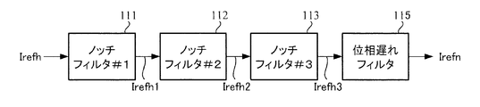
- the specific frequency band removing unit 110 has a configuration in which three notch filters 111, 112, and 113 are connected in series, and a phase delay filter 115 is connected to the final stage. It has become.
- the attenuation frequencies of the notch filters 111, 112 and 113 are fs_trq / 2 and fs_trq, respectively.
- fs_trq ⁇ 3/2.
- the attenuation frequency refers to a frequency having the smallest amplitude in the amplitude characteristics of the filter, and is sometimes called a notch frequency, a center frequency, or the like.
- Each of the notch filters 111 to 113 is designed as a secondary filter, and the frequency characteristic is represented by the following transfer function G when the attenuation frequency is fe .
- s is a Laplace operator
- ⁇ n and ⁇ d are attenuation coefficients.
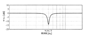
- the amplitude characteristic in this case is an attenuation characteristic as shown in FIG. 6, for example.
- the horizontal axis represents frequency [Hz]
- the vertical axis represents amplitude (gain) [dB]
- the amplitude is the smallest at the attenuation frequency f e (in this example, fs_trq / 2).
- the current command value Itefh is converted.
- the phase delay filter 115 has a first-order or second-order form, and is expressed by a transfer function of the following formula 2 with cut-off frequencies being f n and f d .
- a sample and hold unit exists between the maximum output limiting unit 102 of the torque control system and the specific frequency band removing unit 110 of the current control system. Since the calculation cycle Ts_trq of the torque control system is different from the calculation cycle Ts_cur of the current control system, the current control system cannot receive data (current command value) output from the torque control system in synchronization with the torque control system. For this reason, the data output from the torque control system is stored (sampled) by the sample and hold unit and held until the current control system can receive the data. As a result, data loss can be eliminated. Note that the sample and hold unit may be incorporated into the specific frequency band removing unit 110.
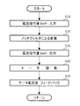
- the current command value Irefh output from the maximum output limiting unit 102 of the torque control system is input to the specific frequency band removing unit 110 of the current control system (step S10).
- the notch filter 1111 receives the current command value Irefh, and converts the current command value Irefh based on the above equation 1 using the held parameter.
- the converted current command value Irefh1 is input to the next-stage notch filter 112, and similarly converted to the current command value Irefh2 based on the above equation 1, and the current command value Irefh2 is further input to the notch filter 113, and similarly Based on Equation 1, the current command value is converted to Irefh3 (step S20).
- the current command value Irefh3 is phase-processed by the final-stage phase delay filter 115 (step S21), and the current command value Irefn thus processed by the specific frequency band removing unit 110 is output (step S30).
- the current command value Irefn is input to the subtraction unit 103, and thereafter, through the same operation as described above, the motor 20 is PWM-driven (step S40), and the motor current value Im detected by the motor current detector 107 is subtracted by the subtraction unit 103. (Step S50).
- FIG. 8 shows the result of applying the present invention to the current command value having the power spectrum shown in FIG.
- FIG. 8 shows the power spectrum of the current command value with the frequency [Hz] on the horizontal axis and the power spectrum [dB] on the vertical axis, as in FIG.
- the steep power spectrum (broken line portion) generated every half frequency of the calculation frequency fs_trq is reduced. I understand.
- the number of notch filters may be changed in accordance with the number of power spectra to be attenuated.
- the specific frequency band removing unit 110 may be configured by only the notch filter 111 and the phase delay filter 115.
- a notch filter having this frequency as an attenuation frequency may be added to the specific frequency band removing unit 110.
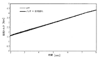
- the phase is a bold line in the Bode diagrams shown in FIGS. 9 (A) and 9 (B).
- the specific frequency band removing unit 110 is configured with the primary LPF of 300 Hz
- the frequency characteristics thereof are as shown by the thin lines in FIGS. 9A and 9B. That is, the LPF is set to be equivalent to 300 Hz so that the gain at 500 Hz matches.
- the frequency characteristic for the phase change is shown in FIG. 10, which shows a case where the phase of 50 Hz recovers by about 4.5 degrees.
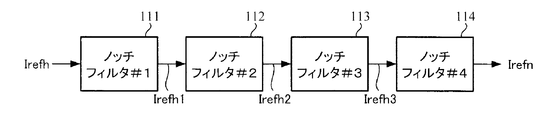
- the specific frequency band removing unit 110 includes the notch filters 111 to 113 and the phase delay filter 115, but may also include the notch filters 111 to 114 as shown in FIG. 14 (second embodiment). .
- the specific frequency band removing unit 110 has a configuration in which four notch filters 111, 112, 113, and 114 are connected in series as shown in FIG.
- the attenuation frequencies of the notch filters 111, 112, 113, and 114 are respectively fs_trq / 2.
- Each of the notch filters 111 to 114 is designed as a secondary filter, and the frequency characteristic is represented by the transfer function G of Equation 1 above.
- the amplitude characteristic in this case is an attenuation characteristic as shown in FIG. 15, for example.
- the horizontal axis represents frequency [Hz]
- the vertical axis represents amplitude (gain) [dB]
- the amplitude is the smallest at the attenuation frequency fe (fs_trq / 2 in this example).
- a sample and hold unit exists between the maximum output limiting unit 102 of the torque control system and the specific frequency band removing unit 110 of the current control system.
- the current command value Irefh output from the maximum output limiting unit 102 of the torque control system is input to the specific frequency band removing unit 110 of the current control system (step S10).
- the notch filter 111 receives the current command value Irefh, and converts the current command value Irefh based on the above equation 1 using the held parameter.
- the converted current command value Irefh1 is input to the next-stage notch filter 112, and similarly converted to the current command value Irefh2 based on the above equation 1, and the current command value Irefh2 is further input to the notch filter 113, and similarly
- the current command value Irefh3 is converted to the current command value Irefh3 based on the formula 1, and the current command value Irefh3 is further input to the notch filter 114 at the final stage, and similarly converted to the current command value Irefhn based on the formula 1 (step S20).
- the current command value Irefn processed by the specific frequency band removing unit 110 is output (step S30).
- the current command value Irefn is input to the subtraction unit 103, and thereafter, through the same operation as described above, the motor 20 is PWM-driven (step S40), and the motor current value Im detected by the motor current detector 107 is subtracted by the subtraction unit 103. (Step S50).
- FIG. 17 shows the result of applying the present invention to the current command value having the power spectrum shown in FIG.
- FIG. 17 shows the power spectrum of the current command value with the frequency [Hz] on the horizontal axis and the power spectrum [dB] on the vertical axis, as in FIG.
- the steep power spectrum (broken line) generated at every half frequency of the calculation frequency fs_trq is reduced. I understand.
- the number of notch filters may be changed according to the number of power spectra to be attenuated.
- the specific frequency band removing unit 110 may be configured by only the notch filter 111.
- a notch filter having this frequency as an attenuation frequency may be added to the specific frequency band removing unit 110.
- the phase is a bold line in the Bode diagrams shown in FIGS. 18 (A) and 18 (B).
- the specific frequency band removing unit 110 is configured with the primary LPF of 300 Hz, the frequency characteristics thereof are as shown by the thin lines in FIGS. That is, the LPF is set to be equivalent to 300 Hz so that the gain at 500 Hz matches.
- the frequency characteristic for the phase change is shown in FIG. 19 and shows a case where the phase of 50 Hz recovers by about 9 degrees.
- the specific frequency band removing unit 110 is disposed after the maximum output limiting unit 102, and the current command value Irefh is input to the specific frequency band removing unit 110.
- a brushless motor may be used as a drive source, and the brushless motor is driven and controlled by a vector control system.
- the vector control system will be described below.
- the vector control system of FIG. 24, and the current command value calculating section 220 is provided to correct by calculating the d-axis current command value i d and the q-axis current command value i q, steering the current command value calculating section 220
- the torque Th, the vehicle speed Vs, the motor angle (rotation angle) ⁇ e , and the motor angular velocity ⁇ calculated by the angular velocity calculating unit 226 are input from the rotation sensor 200A connected to the motor 200.
- D-axis current command value i d and the q-axis current command value i q calculated by the current command value calculating unit 220 is input to the 2-phase / 3-phase conversion unit 221, three-phase current in synchronization with the motor angle theta e
- the command values are converted into Iuref, Ivref, and Iwref.
- the three-phase current command values Iuref, Ivref, Iwref are input to the subtractor 222 (222u, 222v, 222w) and current deviations ⁇ Iu, ⁇ Iv from the motor current values Imu, Imv, Imw detected by the motor current detector 225A. , ⁇ Iw is calculated.
- the calculated current deviations ⁇ Iu, ⁇ Iv, ⁇ Iw are input to the PI control unit 223, and the three-phase voltage control command values Vuref, Vvref, Vwref subjected to PI control are input to the PWM control unit 224 and calculated by the PWM control unit 224.
- the motor 200 is driven via the inverter 225 based on each phase duty.
- the motor current detector 225A is provided in the inverter 225, but it can also be detected by a supply line to the motor 200 or the like.
- a motor current detector 225A at the detected three-phase motor current Imu, Imv, 3-phase / 2-phase conversion unit for converting into two phases in synchronism with Imw the motor angle theta e 227 is provided.
- D-axis current command value computed is corrected by the current command value calculating section 220 i d and the q-axis current command value i q is input to the subtraction unit 222 (222d, 222q), 3-phase / 2-phase conversion by the subtraction unit 222
- Current deviations ⁇ i d and ⁇ i q from the two-phase currents Imd and Imq from the unit 227 are calculated.
- the current deviations ⁇ i d and ⁇ i q are input to the PI control unit 221, and the two-phase voltage command values Vd and Vq subjected to PI control are input to the two-phase / three-phase conversion unit 223 and the two-phase / three-phase conversion unit 223. in is converted to a voltage command value Vuref ⁇ Vwref three-phase synchronous motor angle theta e, subsequent operation similar to the case of FIG. 24 is executed.
- the vector control system in FIG. 24 is a three-phase feedback vector control system that feeds back three-phase motor currents Imu, Imv, and Imw
- the vector control system in FIG. 25 is a three-phase motor current Imu, Imv, Imw.
- the present invention can be applied to both the three-phase feedback vector control system and the two-phase feedback vector control system.
Landscapes
- Engineering & Computer Science (AREA)
- Power Engineering (AREA)
- Chemical & Material Sciences (AREA)
- Combustion & Propulsion (AREA)
- Transportation (AREA)
- Mechanical Engineering (AREA)
- Steering Control In Accordance With Driving Conditions (AREA)
- Power Steering Mechanism (AREA)
- Control Of Ac Motors In General (AREA)
Abstract
Le problème décrit par la présente invention est de fournir un appareil de direction à assistance électrique (comprenant un système de commande vecteur) qui atténue le spectre de puissance se produisant du fait de la relation entre la période de calcul d'un système de commande de couple et la période de calcul d'un système de commande de courant, permettant ainsi une suppression précise des vibrations et du bruit anormal, etc. produits par le spectre de puissance. La solution selon l'invention porte sur un dispositif de direction à assistance électrique qui comporte un système de commande de couple pour calculer une valeur de commande de courant et un système de commande de courant pour commander la valeur de courant de moteur circulant vers un moteur sur la base de la valeur de commande de courant, la période de calcul du système de commande de couple étant égale ou supérieure à la période de calcul du système de commande de courant, et le système de commande de courant étant pourvu d'une unité d'élimination de bande de fréquence spécifique pour atténuer, dans la valeur de commande de courant, la composante d'au moins une fréquence qui est un nombre naturel multiple d'une fréquence équivalent sensiblement à la moitié de la fréquence de calcul du système de commande de couple. L'unité d'élimination de bande de fréquence spécifique est configurée à partir de filtres coupe-bande pour régler la fréquence d'atténuation, ou est configurée à partir des filtres coupe-bande et d'un filtre de retard de phase dans lequel la fréquence de coupure a été fixée sur le côté inférieur à la fréquence d'atténuation.
Priority Applications (4)
| Application Number | Priority Date | Filing Date | Title |
|---|---|---|---|
| CN201780028813.3A CN109153409A (zh) | 2016-05-12 | 2017-05-12 | 电动助力转向装置 |
| EP17796241.2A EP3315387B1 (fr) | 2016-05-12 | 2017-05-12 | Appareil de direction à assistance électrique |
| JP2017556997A JP6274377B1 (ja) | 2016-05-12 | 2017-05-12 | 電動パワーステアリング装置 |
| US15/738,370 US10046790B2 (en) | 2016-05-12 | 2017-05-12 | Electric power steering apparatus |
Applications Claiming Priority (6)
| Application Number | Priority Date | Filing Date | Title |
|---|---|---|---|
| JP2016-095925 | 2016-05-12 | ||
| JP2016095926 | 2016-05-12 | ||
| JP2016-095926 | 2016-05-12 | ||
| JP2016095924 | 2016-05-12 | ||
| JP2016095925 | 2016-05-12 | ||
| JP2016-095924 | 2016-05-12 |
Publications (1)
| Publication Number | Publication Date |
|---|---|
| WO2017195883A1 true WO2017195883A1 (fr) | 2017-11-16 |
Family
ID=60266581
Family Applications (1)
| Application Number | Title | Priority Date | Filing Date |
|---|---|---|---|
| PCT/JP2017/017980 WO2017195883A1 (fr) | 2016-05-12 | 2017-05-12 | Appareil de direction à assistance électrique |
Country Status (5)
| Country | Link |
|---|---|
| US (1) | US10046790B2 (fr) |
| EP (1) | EP3315387B1 (fr) |
| JP (1) | JP6274377B1 (fr) |
| CN (1) | CN109153409A (fr) |
| WO (1) | WO2017195883A1 (fr) |
Cited By (3)
| Publication number | Priority date | Publication date | Assignee | Title |
|---|---|---|---|---|
| JP2019193464A (ja) * | 2018-04-26 | 2019-10-31 | 株式会社デンソー | ステアリング制御装置 |
| CN111038576A (zh) * | 2018-10-11 | 2020-04-21 | 操纵技术Ip控股公司 | 电动助力转向系统中的抖动噪声管理 |
| US20210276612A1 (en) * | 2020-03-09 | 2021-09-09 | Nidec Corporation | Control device and control method for use in electric power steering device, and motor module |
Families Citing this family (6)
| Publication number | Priority date | Publication date | Assignee | Title |
|---|---|---|---|---|
| US10234056B2 (en) * | 2015-04-06 | 2019-03-19 | Mitsubishi Electric Corporation | Control device for actuator, actuator, valve driving device and abnormality detecting method for actuator |
| JP7247508B2 (ja) * | 2018-09-28 | 2023-03-29 | 日本電産株式会社 | ステアリング制御装置およびパワーステアリング装置 |
| JP6639758B1 (ja) * | 2019-05-13 | 2020-02-05 | 三菱電機株式会社 | 制御システムおよびモータ制御装置 |
| CN110937051B (zh) * | 2019-11-04 | 2020-12-15 | 北京理工大学 | 一种实时测量自行车骑行者输出功率的方法 |
| CN113395021B (zh) * | 2021-07-13 | 2022-06-10 | 北京航空航天大学 | 一种基于Buck变换器的无刷直流电机低功耗驱动系统及方法 |
| CN115214764B (zh) * | 2021-12-20 | 2023-08-15 | 广州汽车集团股份有限公司 | 转向控制方法、装置、器件及可读存储介质 |
Citations (3)
| Publication number | Priority date | Publication date | Assignee | Title |
|---|---|---|---|---|
| JP2006340446A (ja) * | 2005-05-31 | 2006-12-14 | Hitachi Via Mechanics Ltd | ディジタルサーボ制御装置及びレーザ加工装置 |
| JP2014141173A (ja) * | 2013-01-24 | 2014-08-07 | Toyota Motor Corp | 車両の操舵制御装置 |
| WO2017030067A1 (fr) * | 2015-08-19 | 2017-02-23 | 日本精工株式会社 | Dispositif de direction assistée électrique |
Family Cites Families (6)
| Publication number | Priority date | Publication date | Assignee | Title |
|---|---|---|---|---|
| US6107767A (en) * | 1998-03-20 | 2000-08-22 | Trw Inc. | Electric assist steering system having an improved motor current controller with notch filter |
| WO2001047762A1 (fr) * | 1999-12-29 | 2001-07-05 | Delphi Technologies, Inc. | Procede et systeme d'amelioration de la stabilite d'un vehicule moteur incorporant un systeme de direction assistee electrique |
| JP5040420B2 (ja) * | 2007-05-07 | 2012-10-03 | 株式会社ジェイテクト | 電動パワーステアリング装置 |
| JP5235536B2 (ja) * | 2008-07-03 | 2013-07-10 | 三菱電機株式会社 | 電動パワーステアリング制御装置 |
| JP5456576B2 (ja) | 2010-05-24 | 2014-04-02 | 三菱電機株式会社 | 電動パワーステアリング装置 |
| CN105083370B (zh) * | 2014-05-09 | 2018-01-16 | 现代摩比斯株式会社 | Mdps的补偿控制装置 |
-
2017
- 2017-05-12 JP JP2017556997A patent/JP6274377B1/ja not_active Expired - Fee Related
- 2017-05-12 WO PCT/JP2017/017980 patent/WO2017195883A1/fr active Application Filing
- 2017-05-12 CN CN201780028813.3A patent/CN109153409A/zh active Pending
- 2017-05-12 EP EP17796241.2A patent/EP3315387B1/fr active Active
- 2017-05-12 US US15/738,370 patent/US10046790B2/en active Active
Patent Citations (3)
| Publication number | Priority date | Publication date | Assignee | Title |
|---|---|---|---|---|
| JP2006340446A (ja) * | 2005-05-31 | 2006-12-14 | Hitachi Via Mechanics Ltd | ディジタルサーボ制御装置及びレーザ加工装置 |
| JP2014141173A (ja) * | 2013-01-24 | 2014-08-07 | Toyota Motor Corp | 車両の操舵制御装置 |
| WO2017030067A1 (fr) * | 2015-08-19 | 2017-02-23 | 日本精工株式会社 | Dispositif de direction assistée électrique |
Cited By (6)
| Publication number | Priority date | Publication date | Assignee | Title |
|---|---|---|---|---|
| JP2019193464A (ja) * | 2018-04-26 | 2019-10-31 | 株式会社デンソー | ステアリング制御装置 |
| JP7095380B2 (ja) | 2018-04-26 | 2022-07-05 | 株式会社デンソー | ステアリング制御装置 |
| CN111038576A (zh) * | 2018-10-11 | 2020-04-21 | 操纵技术Ip控股公司 | 电动助力转向系统中的抖动噪声管理 |
| US11511795B2 (en) | 2018-10-11 | 2022-11-29 | Steering Solutions Ip Holding Corporation | Dither noise management in electric power steering systems |
| US20210276612A1 (en) * | 2020-03-09 | 2021-09-09 | Nidec Corporation | Control device and control method for use in electric power steering device, and motor module |
| US11807315B2 (en) * | 2020-03-09 | 2023-11-07 | Nidec Corporation | Control device and control method for use in electric power steering device, and motor module |
Also Published As
| Publication number | Publication date |
|---|---|
| CN109153409A (zh) | 2019-01-04 |
| JP6274377B1 (ja) | 2018-02-07 |
| EP3315387B1 (fr) | 2019-12-25 |
| EP3315387A4 (fr) | 2018-12-12 |
| JPWO2017195883A1 (ja) | 2018-05-24 |
| US10046790B2 (en) | 2018-08-14 |
| US20180178828A1 (en) | 2018-06-28 |
| EP3315387A1 (fr) | 2018-05-02 |
Similar Documents
| Publication | Publication Date | Title |
|---|---|---|
| JP6274377B1 (ja) | 電動パワーステアリング装置 | |
| JP6658995B2 (ja) | モータ制御装置及びそれを搭載した電動パワーステアリング装置 | |
| JP6566075B2 (ja) | 電動パワーステアリング装置 | |
| JP6222411B2 (ja) | 電動パワーステアリング装置 | |
| JP6597824B2 (ja) | 電動パワーステアリング装置 | |
| JP2008296877A (ja) | 電動パワーステアリング装置 | |
| JP5935960B2 (ja) | 電動パワーステアリング装置 | |
| WO2018016437A1 (fr) | Dispositif de direction assistée électrique | |
| JP2018007454A (ja) | モータ制御装置及びそれを搭載した電動パワーステアリング装置 | |
| JP6697790B2 (ja) | 電動パワーステアリング装置および電動パワーステアリングの制御方法 | |
| JP2017127066A (ja) | モータ制御装置及びそれを搭載した電動パワーステアリング装置 | |
| JP6716031B2 (ja) | 電動パワーステアリング装置および電動パワーステアリングの制御方法 | |
| JP2017175834A (ja) | モータ制御装置及びそれを搭載した電動パワーステアリング装置 | |
| JP2017158245A (ja) | モータ制御装置及びそれを搭載した電動パワーステアリング装置 |
Legal Events
| Date | Code | Title | Description |
|---|---|---|---|
| ENP | Entry into the national phase |
Ref document number: 2017556997 Country of ref document: JP Kind code of ref document: A |
|
| WWE | Wipo information: entry into national phase |
Ref document number: 15738370 Country of ref document: US |
|
| WWE | Wipo information: entry into national phase |
Ref document number: 2017796241 Country of ref document: EP |
|
| NENP | Non-entry into the national phase |
Ref country code: DE |