WO2017195817A1 - 炭化水素の改質方法、有機酸素化物の製造方法、及び有機酸素化物の製造システム - Google Patents
炭化水素の改質方法、有機酸素化物の製造方法、及び有機酸素化物の製造システム Download PDFInfo
- Publication number
- WO2017195817A1 WO2017195817A1 PCT/JP2017/017674 JP2017017674W WO2017195817A1 WO 2017195817 A1 WO2017195817 A1 WO 2017195817A1 JP 2017017674 W JP2017017674 W JP 2017017674W WO 2017195817 A1 WO2017195817 A1 WO 2017195817A1
- Authority
- WO
- WIPO (PCT)
- Prior art keywords
- gas
- organic
- hydrogen
- reforming
- carbon monoxide
- Prior art date
- Legal status (The legal status is an assumption and is not a legal conclusion. Google has not performed a legal analysis and makes no representation as to the accuracy of the status listed.)
- Ceased
Links
Images

Classifications
-
- C—CHEMISTRY; METALLURGY
- C01—INORGANIC CHEMISTRY
- C01B—NON-METALLIC ELEMENTS; COMPOUNDS THEREOF; METALLOIDS OR COMPOUNDS THEREOF NOT COVERED BY SUBCLASS C01C
- C01B3/00—Hydrogen; Gaseous mixtures containing hydrogen; Separation of hydrogen from mixtures containing it; Purification of hydrogen; Reversible storage of hydrogen
- C01B3/02—Production of hydrogen; Production of gaseous mixtures containing hydrogen
- C01B3/32—Production of hydrogen; Production of gaseous mixtures containing hydrogen by reaction of gaseous or liquid organic compounds with gasifying agents, e.g. water, carbon dioxide or air
- C01B3/34—Production of hydrogen; Production of gaseous mixtures containing hydrogen by reaction of gaseous or liquid organic compounds with gasifying agents, e.g. water, carbon dioxide or air by reaction of hydrocarbons with gasifying agents
-
- Y—GENERAL TAGGING OF NEW TECHNOLOGICAL DEVELOPMENTS; GENERAL TAGGING OF CROSS-SECTIONAL TECHNOLOGIES SPANNING OVER SEVERAL SECTIONS OF THE IPC; TECHNICAL SUBJECTS COVERED BY FORMER USPC CROSS-REFERENCE ART COLLECTIONS [XRACs] AND DIGESTS
- Y02—TECHNOLOGIES OR APPLICATIONS FOR MITIGATION OR ADAPTATION AGAINST CLIMATE CHANGE
- Y02P—CLIMATE CHANGE MITIGATION TECHNOLOGIES IN THE PRODUCTION OR PROCESSING OF GOODS
- Y02P20/00—Technologies relating to chemical industry
- Y02P20/50—Improvements relating to the production of bulk chemicals
- Y02P20/52—Improvements relating to the production of bulk chemicals using catalysts, e.g. selective catalysts
Definitions
- the present invention relates to a hydrocarbon reforming method, an organic oxygenate production method, and an organic oxygenate production system.
- This application claims priority on May 12, 2016 based on Japanese Patent Application No. 2016-096161 for which it applied to Japan, and uses the content here.
- Patent Document 1 discloses a method in which a synthesis gas containing hydrogen and carbon monoxide is brought into contact with a metal catalyst such as rhodium and manganese to obtain organic oxygenates such as alcohol, acetaldehyde and acetic acid. Since the reaction efficiency by the metal catalyst is not 100%, unreacted hydrogen and carbon monoxide remain in the produced gas containing the produced organic oxygenate.
- the product gas usually contains hydrocarbons having about 1 to 6 carbon atoms as a by-product. Not only recovering these unreacted hydrogen and carbon monoxide as raw materials, but also reforming by-product hydrocarbons to hydrogen and carbon monoxide by a reforming catalyst.
- organic oxygenates such as alcohol contained in the product gas are recovered by gas-liquid separation in the cooler, and hydrocarbons remaining on the gas component side are introduced into the reforming unit together with water vapor to perform catalytic reaction.
- a method for producing hydrogen and carbon monoxide is disclosed.
- the conventional method is required to be improved because the efficiency and stability of reforming to obtain hydrogen and carbon monoxide from hydrocarbons is low.
- the present invention relates to a method for producing an organic oxygenate capable of efficiently reforming a hydrocarbon produced as a by-product when producing an organic oxygenate from synthesis gas into hydrogen and carbon monoxide, and the method thereof
- a production system and a hydrocarbon reforming method useful for the production method are provided.
- a gas containing hydrocarbons and having an organic oxygenate content of less than 1000 ppm on a molar basis and water vapor are brought into contact with the reforming catalyst, and from the concentration of hydrogen and the concentration of carbon monoxide contained in the gas
- a hydrocarbon reforming method comprising a reforming step of obtaining a reformed gas having a higher hydrogen concentration and carbon monoxide concentration.
- Separation that reduces the content of the organic oxygenate contained in the gas to less than 1000 ppm on a molar basis by contacting the gas with activated carbon and separating at least a part of the organic oxygenate from the gas.
- the hydrocarbon reforming method according to [1] comprising a step.
- a production step of bringing a synthesis gas containing hydrogen and carbon monoxide into contact with a synthesis catalyst to obtain a product gas containing an organic oxygenate and a hydrocarbon, and separating at least a part of the organic oxygenate from the product gas A separation step of obtaining a separation gas containing hydrocarbons, bringing the separation gas and water vapor into contact with a reforming catalyst, and a concentration of hydrogen higher than a concentration of hydrogen and a concentration of carbon monoxide contained in the separation gas
- a reforming step for obtaining a reformed gas having a concentration of carbon monoxide, and a method for producing an organic oxygenate having a content of the organic oxygenate in the separation gas used in the reforming step The manufacturing method of the organic oxygenate which is less than 1000 ppm on a molar basis.
- [4] The method for producing an organic oxygenate according to [3], further including a recycling step of bringing the reformed gas into contact with the synthesis catalyst to obtain the product gas.
- [5] The method for producing an organic oxygenate according to [3] or [4], wherein the organic oxygenate is at least one selected from the group consisting of ethanol and ethyl acetate.
- [6] The method for producing an organic oxygenate according to any one of [3] to [5], wherein the separation step includes an adsorption treatment for adsorbing the organic oxygenate on activated carbon.
- a synthesis catalyst that generates organic oxygenates and hydrocarbons from hydrogen and carbon monoxide is provided. When a synthesis gas containing hydrogen and carbon monoxide is introduced, the organic oxygenates and hydrocarbons are removed by the action of the synthesis catalyst.
- the hydrocarbon produced as a by-product when an organic oxygenate is produced from synthesis gas is efficiently reformed to hydrogen and carbon monoxide. Can do.
- the hydrocarbon can be efficiently reformed into hydrogen and carbon monoxide.
- the production method of the organic oxygenate according to the first aspect of the present invention includes a production step of bringing a synthesis gas containing hydrogen and carbon monoxide into contact with a synthesis catalyst to obtain a production gas containing an organic oxygenate and a hydrocarbon, and the production gas A separation step of separating at least a part of the organic oxygenate from the mixture to obtain a separation gas containing the hydrocarbon, bringing the separation gas and water vapor into contact with a reforming catalyst, and a concentration of hydrogen contained in the separation gas And a reforming step of obtaining a reformed gas having a hydrogen concentration and a carbon monoxide concentration higher than the concentration of carbon monoxide.
- the organic oxygenate can be recovered in the separation step.
- a separation gas in which the total of the organic oxygenates is reduced to less than 1000 ppm on a molar basis is used in the reforming step.
- the production process is a process in which a synthesis gas is brought into contact with a synthesis catalyst to obtain a production gas containing organic oxygenates and hydrocarbons.
- a synthesis gas is brought into contact with a synthesis catalyst to obtain a production gas containing organic oxygenates and hydrocarbons.
- a product gas containing the target organic oxygenate can be obtained.
- it can be performed according to a known method such as Patent Document 1.
- the synthesis gas is preferably composed mainly of hydrogen and carbon monoxide.
- the lower limit of the total of hydrogen and carbon monoxide in the synthesis gas is preferably 50 to 70% by volume or more.
- the upper limit of the total of hydrogen and carbon monoxide in the synthesis gas is not particularly limited, and may be 100% by volume.
- the volume ratio represented by hydrogen / carbon monoxide (hereinafter sometimes referred to as H 2 / CO ratio) is preferably from 0.1 to 10, and more preferably from 0.5 to 3.
- H 2 / CO ratio is within the above range, in the reaction for synthesizing the organic oxygenate from the synthesis gas, the stoichiometrically appropriate range is obtained, and the synthesis efficiency of the organic oxygenate can be improved.
- the synthesis gas may contain an inert gas. If the synthesis gas contains an inert gas, the synthesis efficiency of the organic oxygenates may be improved. Examples of the inert gas include nitrogen and argon. The content of the inert gas is preferably 5 to 30% by volume with respect to 100% by volume of the synthesis gas. Although it is preferable that the synthesis gas does not contain impurities other than hydrogen, carbon monoxide, and inert gas, in practice, gases such as methane, ethane, ethylene, and water generated in the reaction system are impurities. May be included.
- the temperature at which the synthesis gas and the synthesis catalyst are brought into contact is, for example, preferably 150 to 450 ° C., more preferably 250 to 300 ° C.
- the pressure at which the synthesis gas and the synthesis catalyst are brought into contact is preferably, for example, 0.5 to 10 MPa, and more preferably 0.8 to 5 MPa.
- the synthesis gas supply rate is, for example, a space velocity of the synthesis gas in the reaction bed (a value obtained by dividing the gas supply amount per unit time by the catalyst amount (volume conversion)) of 10 to 100,000 L / L-
- the catalyst / h can be adjusted. More preferably, it is 2000 to 20000 L / L-catalyst / h.
- the synthesis gas introduced into the reaction tube flows in contact with the synthesis catalyst in the reaction bed.
- an oxygenate having 2 carbon atoms such as ethanol, acetic acid, or acetaldehyde, or an oxygenate having 4 carbon atoms such as ethyl acetate.
- Organic oxygenates such as are produced.
- hydrocarbons having about 1 to 6 carbon atoms are produced as by-products.
- organic oxygenates examples include ethanol, acetic acid, acetaldehyde, ethyl acetate, methanol, 1-propanol, 1-butanol, 1-pentanol, methyl acetate, propyl acetate, butyl acetate, pentyl acetate, acetaldehyde diethyl acetal, and the like. It is done. When a plurality of types of organic oxygenates are included, the total of these is less than 1000 ppm.
- the hydrocarbon examples include methane, ethane, ethylene, propane, propylene, butane, butene, pentane, hexane and the like.
- the type and amount of the synthesis catalyst used in the production step is not particularly limited, and known metal catalysts used for obtaining organic oxygenates having 2 or more carbon atoms such as alcohol, acetaldehyde, acetic acid, and ester from synthesis gas are available.
- a metal catalyst containing one or more platinum group elements selected from ruthenium, rhodium, palladium, osmium, iridium and platinum is preferable from the viewpoint of increasing the selectivity.
- the synthetic catalyst may contain the following hydrogenation active metal and co-active metal as a metal (optional catalyst metal) other than the platinum group element.
- Examples of the hydrogenation active metal include alkali metals such as lithium and sodium; chromium and molybdenum, elements belonging to Group 6 of the periodic table; manganese, rhenium and other elements belonging to Group 7 of the periodic table; iron, ruthenium Elements belonging to Group 8 of the periodic table; cobalt, elements belonging to Group 9 of the periodic table (excluding platinum group elements); elements such as nickel, belonging to Group 10 of the periodic table (however, platinum) Excluding group elements).
- These hydrogenation active metals may be used individually by 1 type, and may be used in combination of 2 or more type. Further, some or all of these hydrogenation-activated metals may be oxidized or sulfided.
- co-active metal examples include one or more selected from titanium, vanadium, chromium, boron, magnesium, lanthanoids, and elements belonging to Group 13 of the periodic table. Among these, titanium, magnesium, and vanadium are preferable. Titanium is more preferred.
- the synthesis catalyst may have a carrier supporting a metal.
- the type of the carrier is not particularly limited, and a carrier used in a conventional catalyst can be applied.
- a porous carrier is preferable.
- the material of the porous carrier is not particularly limited, and examples thereof include silica, zirconia, titania, magnesia, alumina, zeolite and the like, and among them, various products having different specific surface areas and pore diameters can be procured in the market. Silica is preferred.
- the size of the porous carrier examples include a particle diameter of 0.5 to 5000 ⁇ m. The particle size is adjusted by sieving.
- the porous carrier preferably has a narrowest particle size distribution.
- the total pore volume of the porous carrier is preferably 0.01 to 1.0 mL / g, more preferably 0.1 to 0.8 mL / g, and further preferably 0.3 to 0.7 mL / g.
- the total pore volume can be measured by a water titration method.
- the water titration method is a method in which water molecules are adsorbed on the surface of a porous carrier and the pore distribution is measured from the condensation of the molecules.
- the average pore diameter of the porous carrier is preferably 0.01 to 20 nm, more preferably 2 to 20 nm, further preferably more than 5 nm and less than 14 nm, particularly preferably more than 5 nm and not more than 10 nm.
- the average pore diameter is a value measured by the following method. When the average pore diameter is 0.1 nm or more and less than 10 nm, it is calculated from the total pore volume and the BET specific surface area. When the average pore diameter is 10 nm or more, it is measured by a mercury porosimetry porosimeter.
- the total pore volume is a value measured by a water titration method
- the BET specific surface area is a value calculated from the amount of adsorption and the pressure at that time using nitrogen as an adsorption gas.
- mercury intrusion method mercury is pressurized and pressed into the pores of the porous carrier, and the average pore diameter is calculated from the pressure and the amount of mercury inserted.
- the specific surface area of the porous carrier is preferably 1 ⁇ 1000m 2 / g, more preferably from 300 ⁇ 800m 2 / g, more preferably 400 ⁇ 700m 2 / g.
- the specific surface area is a BET specific surface area measured by a BET gas adsorption method using nitrogen as an adsorption gas.
- Examples of the supported amount of the platinum group element with respect to 100 parts by mass of the carrier include 0.5 parts by mass or more and 10 parts by mass or less.
- the supported amount of the hydrogenation active metal is, for example, 1 to 10 parts by mass with respect to 100 parts by mass of the porous carrier, with the total of the platinum group element and the hydrogenation active metal.
- Examples of the loading amount of the co-active metal include 0.01 to 20 parts by mass with respect to 100 parts by mass of the carrier.
- the separation step is a step of separating at least part of the organic oxygenate from the product gas obtained in the production step to obtain a separation gas containing the hydrocarbon.
- the product gas derived from the reaction tube is introduced into a cooler and cooled to about 5 to 50 ° C., thereby condensing an organic oxygenate having a boiling point lower than the cooling temperature and moisture, thereby known gas-liquid A method of recovering organic oxygenates by a separation method is mentioned.
- the boiling point of butane is ⁇ 1 ° C.
- hydrocarbons having 1 to 4 carbon atoms do not condense only by cooling to about 5 to 50 ° C., and remain on the gas side by gas-liquid separation.
- the separation gas obtained by gas-liquid separation by cooling usually contains mist (micro liquid phase particles) of about submicron to submillimeter.
- mist micro liquid phase particles
- the separated gas that has passed through the demister is dried by removing the mist, and contains hydrocarbons, unreacted hydrogen, carbon monoxide, and the like.
- the present inventors passed the separation gas through an adsorber (activated carbon adsorber) filled with activated carbon in order to further separate the organic oxygenate remaining in the separated gas that passed through the demister.
- the total amount of organic oxygenates contained in the separation gas is less than 1000 ppm (0.1 mol%), preferably less than 500 ppm (0.05 mol%), more preferably 100 ppm (0.01 mol%) on a molar basis. It has been found that the reforming efficiency in the latter stage can be significantly improved and the reforming reaction can be stabilized by lowering the ratio to below.
- the organic oxygenated product adsorbed on the activated carbon is a desired product in the production process, it is preferably recovered.
- a recovery process for recovering organic oxygenates from activated carbon for example, by heating the activated carbon, the organic oxygenates adsorbed on the activated carbon are vaporized and desorbed from the activated carbon, and the desorbed organic oxygenate is cooled in a cooler.
- recovering by etc. is mentioned.
- the method of reducing the total amount of organic oxygenates contained in the separation gas to less than 1000 ppm is not limited to the method of adsorbing to activated carbon.
- adsorbents such as molecular sieve, silica gel, clay, activated alumina, and zeolite. You may apply the method of making it adsorb
- the activated carbon adsorption method is preferable because it has a high ability to separate organic oxygenates.
- the separation gas and water vapor are brought into contact with the reforming catalyst, and the reformed gas having a hydrogen concentration and a carbon monoxide concentration higher than the hydrogen concentration and the carbon monoxide concentration contained in the separation gas.
- the total of the organic oxygenates in the separation gas used in the reforming step is less than 1000 ppm (0.1 mol%), preferably less than 500 ppm (0.05 mol%) on a molar basis. More preferably, it is less than 100 ppm (0.01 mol%). Ideally, it is 0 ppm.
- hydrocarbons contained in the separation gas can be reformed by introducing the separation gas and water vapor into a reaction tube containing a reforming catalyst and controlling the temperature and pressure in the reaction tube.
- the hydrocarbon is reformed by the action of water vapor and the reforming catalyst to generate hydrogen and carbon monoxide, and the concentration of hydrogen and the concentration of carbon monoxide in the separation gas are increased.
- it can be performed according to a known method such as Patent Document 1.
- the concentration of hydrogen (in terms of mol%) contained in the reformed gas is preferably 1.1 to 2.0 times the concentration of hydrogen contained in the separation gas.
- the concentration (mole% conversion) of carbon monoxide contained in the reformed gas is preferably 1.1 to 2.0 times the concentration of carbon monoxide contained in the separation gas.
- the temperature at which the separation gas and the reforming catalyst are brought into contact is preferably 600 to 1000 ° C., more preferably 700 to 900 ° C.
- the pressure at which the separation gas and the reforming catalyst are brought into contact is preferably, for example, 0.5 to 10 MPa, and more preferably 0.6 to 2 MPa.
- the space velocity of the separation gas in the reaction bed is 10 to 10,000 L / L- Catalyst / h, preferably 100 L / L-catalyst / h to 10000 L / L-catalyst / h can be adjusted.
- the type and amount of the reforming catalyst used in the reforming step are not particularly limited, and known catalysts used for obtaining hydrogen and carbon monoxide from hydrocarbons and steam can be applied.
- nickel, ruthenium From the viewpoint of improving the reforming efficiency, a metal catalyst containing at least one selected from platinum, rhodium is preferable.
- an alumina-supported nickel-based catalyst main metal NiO
- the reforming catalyst may have a carrier supporting a metal.
- the type of the carrier is not particularly limited, and a carrier used in a conventional catalyst can be applied.
- the porous carrier that can be used as the carrier of the synthetic catalyst described above is preferable.
- the size of the reforming catalyst can be selected so as to obtain an appropriate packing density and a pressure loss during gas flow according to the reaction tube diameter and gas flow rate.
- the particle diameter of the reforming catalyst is preferably 1 to 5 mm, more preferably 2 to 4 mm.
- the particle diameter of the reforming catalyst can be adjusted by sieving.
- the separated gas introduced into the reaction tube flows along with the water vapor while contacting the reforming catalyst in the reaction bed to generate hydrogen and carbon monoxide, and the reformed gas in which the concentration of hydrogen and carbon monoxide is increased. It becomes. Since this reformed gas is useful as a raw material for obtaining a product gas containing an organic oxygenate in the production process, the reformed gas can be supplied to the production process alone or mixed with a synthesis gas.
- the method for producing an organic oxygenated product of the present embodiment may include a [reuse step] in which the reformed gas is brought into contact with the synthesis catalyst by the above supply to obtain the product gas.
- the production system for an organic oxygenate includes a generation unit, a separation unit, and a reforming unit.
- generation part is equipped with the synthetic catalyst which produces
- a synthesis gas containing hydrogen and carbon monoxide is introduced into the production section, a production gas containing an organic oxygenate and a hydrocarbon is produced by the action of the synthesis catalyst.
- the separation unit includes a cooler and an activated carbon adsorber or a scrubber. The cooler is preferably installed upstream of the activated carbon or scrubber.
- the reforming unit includes a reforming catalyst that generates carbon monoxide and hydrogen from hydrocarbon and steam.
- the concentration of hydrogen (in terms of mol%) contained in the reformed gas is preferably 1.1 to 2.0 times the concentration of hydrogen contained in the separation gas.
- the concentration (mole% conversion) of carbon monoxide contained in the reformed gas is preferably 1.1 to 2.0 times the concentration of carbon monoxide contained in the separation gas.
- the method for producing the organic oxygenate of the first aspect of the present invention described above is carried out, so that the reforming efficiency of the hydrocarbons contained in the separation gas is increased, and the target organic oxygen It is possible to increase the CO conversion rate to the chemical compound.
- the total amount of organic oxygenates in the separation gas obtained in the separation part is preferably less than 1000 ppm, more preferably less than 500 ppm, and even more preferably less than 100 ppm on a molar basis.
- concentration of the organic oxygenate in the separated gas the more the reforming catalyst can be prevented from being poisoned and the reforming efficiency can be increased.
- the total of organic oxygenates in the separation gas used in the reforming section is preferably less than 1000 ppm, more preferably less than 500 ppm, and even more preferably less than 100 ppm on a molar basis.
- concentration of the organic oxygenate in the separated gas the more the reforming catalyst can be prevented from being poisoned and the reforming efficiency can be increased.
- FIG. 1 shows an example of a production system for organic oxygenates.
- the production system 10 includes a reactor 1 and a reactor 2 connected in series to form a reaction bed filled with a synthesis catalyst, a cooler 3 having a demister 3a connected to an outlet of the reactor 2, and a cooler 3 and an activated carbon adsorption tower 4 having an activated carbon tank filled with activated carbon.
- Activated carbon adsorption towers are installed in two or more in series, filled with different types of activated carbon, or installed in parallel in two or more towers so that they can be replaced when the adsorption capacity decreases. Good.
- the downstream side of the activated carbon adsorption tower 4 is branched into a bypass line and a reforming line.
- the bypass line connects the outlet of the activated carbon adsorption tower 4 to the inlet of the reactor 1 so that the separated gas derived from the activated carbon adsorption tower 4 can be supplied to the reactor 1.
- the reforming line connects the outlet of the activated carbon adsorption tower 4 to the reformer 5 and is connected to the reforming line before the reformer 5 and the hydrocarbons contained in the separated gas derived from the activated carbon adsorption tower 4. It is possible to supply the steam from the steam supply pipe to the reformer 5.
- a cooler 6 is installed on the downstream side of the reformer 5.
- the reformed gas led out from the reformer 5 is cooled, and the water vapor is liquefied and recovered.
- the reformed gas dried by the cooler 6 can be supplied to the reactor 1.
- a gas booster (GB) and a mass flow controller (MFC) are installed at a desired position of a line (pipe) through which gas flows, and the gas pressure and gas flow rate can be adjusted. .
- the reactors 1 and 2 may be filled with only the synthetic catalyst, or may be filled with the synthetic catalyst and the diluent.
- the diluent is for preventing excessive heat generation of the synthesis catalyst during the production of the organic oxygenates, for example, the same as the carrier of the synthesis catalyst, quartz sand, alumina balls, aluminum balls, aluminum shots, etc. Is mentioned.
- Two reactors 1 and 2 are not necessarily required in series, but only reactor 1 may be used, or two or more reactors may be installed in parallel.
- the reactors 1 and 2 and the reformer 5 are preferably materials that are inert to the synthesis gas and the separation gas, and preferably tubular materials that can withstand heating of about 100 to 800 ° C. and pressurization of about 10 MPa, For example, a stainless steel cylindrical tube is used.
- the coolers 3 and 6 known ones can be applied, and at least the cooler 3 is preferably provided with a known demister.
- the kind of demister is not specifically limited, For example, a mesh demister is mentioned.
- the activated carbon adsorption tower 4 is preferably a porous activated carbon having a large surface area and arranged so that gas can flow.
- the activated carbon adsorption tower 4 includes a heating means capable of heating the activated carbon, and a line branched on the downstream side of the activated carbon adsorption tower 4 in order to recover the organic oxygenates desorbed from the activated carbon by heating. It may be.
- a gas containing hydrocarbons and having a total content of organic oxygenates of less than 1000 ppm on a molar basis and water vapor are brought into contact with the reforming catalyst,
- the hydrogen concentration (in terms of mol%) contained in the reformed gas is preferably 1.1 to 2.0 times the concentration of hydrogen contained in the gas.
- the concentration of carbon monoxide contained in the reformed gas (in terms of mol%) is preferably 1.1 to 2.0 times the concentration of carbon monoxide contained in the gas.
- the modification step of the third aspect can be applied as the modification step of the first aspect of the present invention described above.
- the separation gas to be reformed in the third aspect is not necessarily limited to the separation gas derived from the product gas of the first aspect.
- the modification step of the third aspect can be performed in the same manner as the modification step of the first aspect.
- the organic oxygenate and the hydrocarbon-containing gas are brought into contact with activated carbon, and the organic oxygenate is separated from the gas to separate the organic oxygenate from the gas.
- separation process which reduces the sum total of oxygenates to less than 1000 ppm on a molar basis.
- the gas containing the organic oxygenate and the hydrocarbon in the separation step of the third aspect is not necessarily limited to the product gas of the first aspect.
- the separation step of the third aspect can be performed in the same manner as the separation step of the first aspect.
- Rhodium chloride trihydrate (RhCl 3 ⁇ 3H 2 O) 15.4 g, lithium chloride monohydrate (LiCl ⁇ H 2 O) 0.96 g, manganese chloride tetrahydrate (MnCl 2 ⁇ 4H 2 O) ) 122 mL of an aqueous solution containing 8.66 g was dropped onto the primary support, impregnated, dried at 110 ° C. for 3 hours, and further calcined at 400 ° C. for 3 hours to obtain catalyst particles ⁇ of the synthetic catalyst 1.
- catalyst particles ⁇ of the synthesis catalyst 2 were subjected to the same reduction treatment as the catalyst particles ⁇ .
- the reactor 1 and the reactor 2 connected in series were heated at 300 ° C. for 4 hours while flowing a reducing gas (hydrogen concentration 30 vol%, nitrogen concentration 70 vol%) at a pressure of 0.3 MPaG at 6 NL / min.
- the synthesis catalyst was subjected to a reduction treatment again.
- alumina-supported nickel-based catalyst for steam reforming hydrocarbons such as methane, made of stainless steel with an inner diameter of 29.9 mm and a length of 700 mm
- Hydrogen was passed through the reforming reactor at a pressure of 0.3 MPaG at a rate of 3 NL / min and steam of 3.6 NL / min.
- the temperature was increased from 150 ° C. to 760 ° C. at a rate of 2 ° C./min, and reduced to the reforming catalyst. Treated.
- Procedure 1 The raw synthesis gas was introduced into the reactor 1 and then passed through the reactor 2 to perform a production step in which an organic oxygenate and a hydrocarbon having 1 to 6 carbon atoms were produced by the synthesis catalyst.
- the product gas led out from the outlet of the reactor 2 was passed through a cooler to separate most of the organic oxygenates as liquefied components.
- a gas component containing hydrocarbons was led out as a separation gas from the outlet of the cooler.
- Step 2 Among the branched circulation lines, the separation gas is circulated through a bypass line not equipped with a reformer, and while increasing the gas flow rate of the entire system to an appropriate amount, the temperature of the reactor 1 and the reactor 2 is increased to a desired appropriate temperature. Raised.
- Procedure 3 A part of the separated gas that circulates the bypass line is circulated together with steam to the reforming line equipped with the reformer, and the concentration of hydrogen and carbon monoxide is increased by the reforming reaction. A reforming step for obtaining a reformed gas was performed.
- Procedure 1 After the reaction bed temperature was lowered to 240 ° C., a mixed gas having the composition shown in Table 1 was circulated at 6 NL / min, and the reaction pressure was increased to 2.4 MPa. The produced gas was cooled as a separated gas after being cooled by a cooler (refrigerant temperature 5 ° C.). The reaction temperature was raised to 280 to 290 ° C. at a rate of 1 ° C./minute, and when the temperature was stabilized, the reaction was started. Details of Procedure 2: The pressure was increased from 0.9 MPaG to 2.44 MPaG with a gas booster (GB) while introducing the separation gas into the bypass line.
- GB gas booster
- the bypass gas flow rate was increased by mass flow (MFC) to 36 NL / min.
- MFC mass flow
- the reaction temperature in reactors 1 and 2 was adjusted to 280 to 290 ° C.
- the reforming step in the procedure 3 was performed when the concentration of hydrocarbons in the gas circulating in the system increased. Details of Procedure 3: Water vapor is passed through the reformer 5 at a flow rate of 3 NL / min, the outlet temperature is raised to 760 ° C., and the temperature stabilizes, and then the separated gas flowing through the bypass line is reformed.
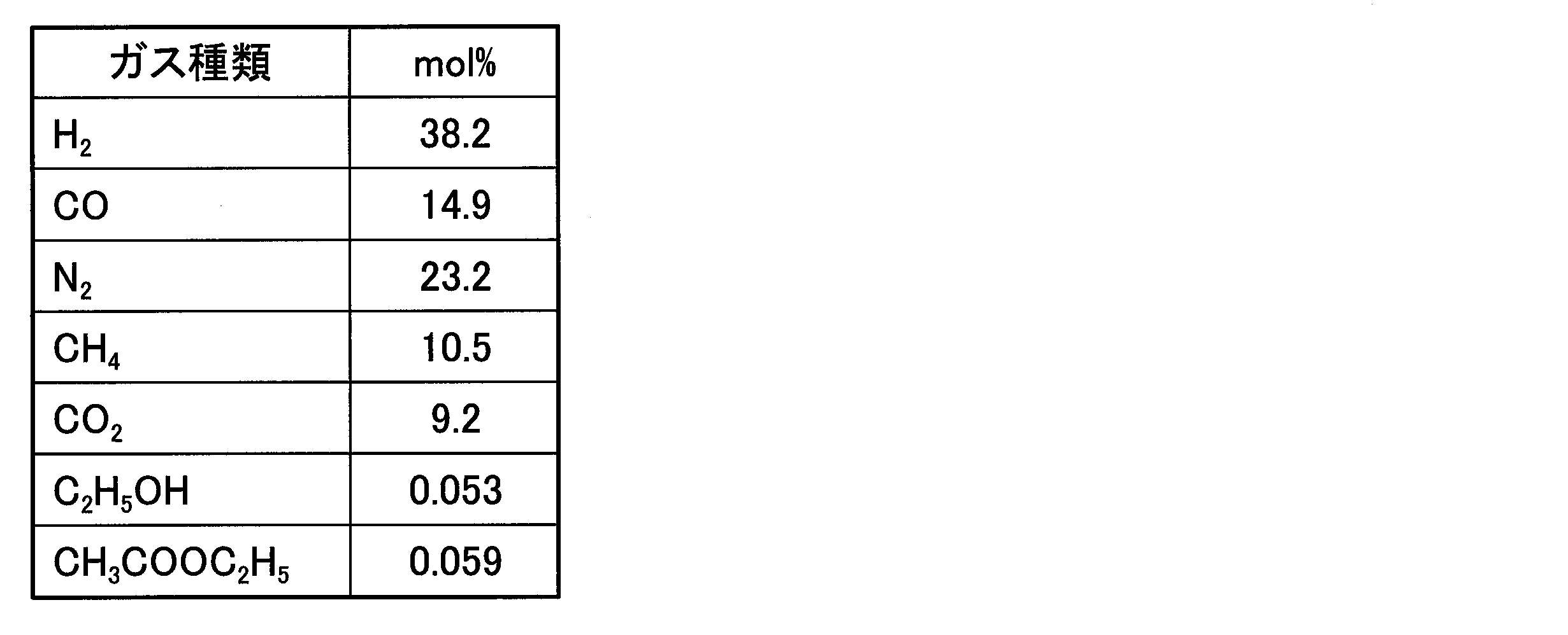
- the gas flow rate was increased to 16.5 NL / min. Thereafter, the reforming reaction bed outlet temperature was stabilized at 760 ° C., and then the reformer inlet gas composition was analyzed by gas chromatography. Table 3 shows the result of analyzing the reforming outlet gas. Further, Table 4 shows theoretical values obtained by calculating the equilibrium composition at 760 ° C. and 1.0 MPa (0.9 MPaG) in the case of the separation gas composition shown in Table 2.
- the reformer inlet gas contained more than 1000 ppm (0.1 mol%) of ethanol and ethyl acetate produced in the reactors 1 and 2 on a molar basis.
- the reforming catalyst was poisoned by these organic oxygenates and the reforming efficiency was lowered.
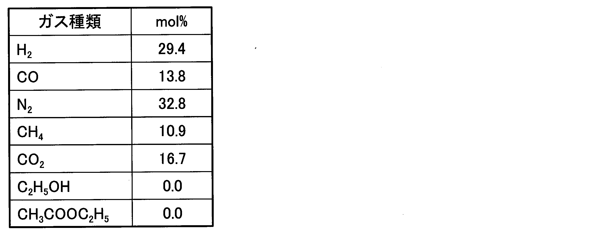
- Example 1 As shown in FIG. 1, an activated carbon adsorption tower 4 filled with 860 g of activated carbon (manufactured by Nippon Enviro Chemicals Co., Ltd .: granular white rice cake G2c10 / 20-2) was installed before the reforming line.
- the activated carbon adsorption tower 4 has an ability to reduce the total of organic oxygenates such as ethanol and ethyl acetate contained in the separation gas to 10 ppm or less on a molar basis.
- Table 5 shows the composition of the separation gas derived from the outlet of the activated carbon adsorption tower 4.
- the reforming catalyst stably exhibited excellent efficiency as theoretically by separating the organic oxygenates such as ethanol and ethyl acetate produced in the reactor 1 with the activated carbon adsorption tower 4. it is obvious. Furthermore, under this condition, CO 2 is reduced from 16.7 mol% to 11.8 mol%, and a part of CO 2 is also converted to CO, and it is clear that the carbon source can be used more effectively.
- Example 2 The same system as in Example 1 was used, and the procedure was substantially the same, but the organic oxygenate was produced according to the following procedure, which was partially different. Details of Procedure 1: After the reaction bed temperature was lowered to 240 ° C., a mixed gas having the composition shown in Table 8 was passed at 3.5 NL / min, and the reaction pressure was increased to 2.05 MPa. The produced gas was cooled as a separated gas after being cooled by a cooler (refrigerant temperature 5 ° C.). The reaction temperature was raised to 280 to 290 ° C. at a rate of 1 ° C./minute, and when the temperature was stabilized, the reaction was started.
- Procedure 1 After the reaction bed temperature was lowered to 240 ° C., a mixed gas having the composition shown in Table 8 was passed at 3.5 NL / min, and the reaction pressure was increased to 2.05 MPa. The produced gas was cooled as a separated gas after being cooled by a cooler (refrigerant temperature 5 ° C.). The reaction
- the amount of the separation gas introduced into the reactor 1 from the bypass line was 21 NL / min together with the newly introduced synthesis gas.
- the reaction temperature in reactors 1 and 2 was adjusted to 280 to 290 ° C.
- the reforming step of procedure 3 was performed. Details of Procedure 3: Water vapor is passed through the reformer 5 at a flow rate of 3.7 NL / min, the outlet temperature is raised to 778 ° C., and after the temperature has stabilized, the separation gas flowing through the bypass line is The gas was passed through the reformer 5 and the gas flow rate was increased to 17.5 NL / min.
- the reactor 1 inlet gas composition was changed to Table 9
- the reactor 2 outlet gas composition was changed to Table 10
- the cooler outlet gas composition was changed to Table 11
- Table 12 shows the reformer inlet gas composition
- Table 13 shows the reformer outlet gas composition.
- Table 14 shows theoretical values obtained by calculating the equilibrium composition at 778 ° C. and 0.77 MPa (0.67 MPaG) in the case of the separation gas composition shown in Table 12.
- the hydrocarbon produced as a by-product when an organic oxygenate is produced from synthesis gas is efficiently reformed to hydrogen and carbon monoxide. Can do.
- the hydrocarbon can be efficiently reformed into hydrogen and carbon monoxide.
Landscapes
- Chemical & Material Sciences (AREA)
- Chemical Kinetics & Catalysis (AREA)
- Organic Chemistry (AREA)
- Health & Medical Sciences (AREA)
- General Health & Medical Sciences (AREA)
- Engineering & Computer Science (AREA)
- Combustion & Propulsion (AREA)
- Inorganic Chemistry (AREA)
- Organic Low-Molecular-Weight Compounds And Preparation Thereof (AREA)
- Hydrogen, Water And Hydrids (AREA)
- Catalysts (AREA)
- Low-Molecular Organic Synthesis Reactions Using Catalysts (AREA)
Abstract
水素及び一酸化炭素を含む合成ガスを合成触媒に接触させ、有機酸素化物及び炭化水素を含む生成ガスを得る生成工程と、前記生成ガスから前記有機酸素化物を分離し、前記炭化水素を含む分離ガスを得る分離工程と、前記分離ガスと、水蒸気とを改質触媒に接触させ、前記分離ガスに含まれる水素の濃度及び一酸化炭素の濃度よりも、水素の濃度及び一酸化炭素の濃度を高めた改質ガスを得る改質工程と、を有する有機酸素化物の製造方法であって、前記改質工程で用いる前記分離ガス中の前記有機酸素化物の合計は、モル基準で1000ppm未満である、有機酸素化物の製造方法。
Description
本発明は、炭化水素の改質方法、有機酸素化物の製造方法、及び有機酸素化物の製造システムに関する。
本願は、2016年5月12日に、日本に出願された特願2016-096161号に基づき優先権を主張し、その内容をここに援用する。
本願は、2016年5月12日に、日本に出願された特願2016-096161号に基づき優先権を主張し、その内容をここに援用する。
水素及び一酸化炭素を含む合成ガスをロジウム、マンガン等の金属触媒に接触させ、アルコール、アセトアルデヒド、酢酸等の有機酸素化物を得る方法が特許文献1に開示されている。前記金属触媒による反応効率は100%ではないため、生成された有機酸素化物を含む生成ガス中には未反応の水素及び一酸化炭素が残っている。また、生成ガス中には副生成物として炭素数1~6程度の炭化水素が含まれることが通常である。これらの未反応の水素及び一酸化炭素を回収して原料とするだけでなく、改質用触媒によって副生成物の炭化水素を水素及び一酸化炭素に改質することが行われている。
具体的には、冷却器における気液分離によって、生成ガスに含まれるアルコール等の有機酸素化物を回収し、ガス成分側に残った炭化水素を水蒸気とともに改質部へ導入して、触媒反応により水素及び一酸化炭素を生成する方法が開示されている。
具体的には、冷却器における気液分離によって、生成ガスに含まれるアルコール等の有機酸素化物を回収し、ガス成分側に残った炭化水素を水蒸気とともに改質部へ導入して、触媒反応により水素及び一酸化炭素を生成する方法が開示されている。
しかしながら、従来方法では炭化水素から水素及び一酸化炭素を得る改質の効率や安定性が低いため、改良が求められている。
本発明は、合成ガスから有機酸素化物を生成した際に副生成物として生成される炭化水素を効率的に水素及び一酸化炭素に改質することが可能な、有機酸素化物の製造方法及びその製造システム、並びにその製造方法に有用な炭化水素の改質方法を提供する。
[1] 炭化水素を含み、有機酸素化物の含有量がモル基準で1000ppm未満であるガスと、水蒸気とを改質触媒に接触させ、前記ガスに含まれる水素の濃度及び一酸化炭素の濃度よりも高い水素の濃度及び一酸化炭素の濃度を有する改質ガスを得る改質工程を有する、炭化水素の改質方法。
[2] 前記ガスを活性炭に接触させ、前記有機酸素化物の少なくとも一部を前記ガスから分離することにより、前記ガスに含まれる前記有機酸素化物の含有量をモル基準で1000ppm未満に低下させる分離工程を有する、[1]に記載の炭化水素の改質方法。
[3] 水素及び一酸化炭素を含む合成ガスを合成触媒に接触させ、有機酸素化物及び炭化水素を含む生成ガスを得る生成工程と、前記生成ガスから前記有機酸素化物の少なくとも一部を分離し、前記炭化水素を含む分離ガスを得る分離工程と、前記分離ガスと、水蒸気とを改質触媒に接触させ、前記分離ガスに含まれる水素の濃度及び一酸化炭素の濃度よりも高い水素の濃度及び一酸化炭素の濃度を有する改質ガスを得る改質工程と、を有する有機酸素化物の製造方法であって、前記改質工程で用いる前記分離ガス中の前記有機酸素化物の含有量は、モル基準で1000ppm未満である、有機酸素化物の製造方法。
[4] 前記改質ガスを前記合成触媒に接触させ、前記生成ガスを得る再利用工程を有する、[3]に記載の有機酸素化物の製造方法。
[5] 前記有機酸素化物が、エタノール及び酢酸エチルからなる群から選択される少なくとも1つである、[3]又は[4]に記載の有機酸素化物の製造方法。
[6] 前記分離工程は、前記有機酸素化物を活性炭に吸着させる吸着処理を有する、[3]~[5]の何れか一項に記載の有機酸素化物の製造方法。
[7] 前記活性炭に吸着した前記有機酸素化物を気化または脱着させて回収する回収処理を有する、[6]に記載の有機酸素化物の製造方法。
[8] 水素及び一酸化炭素から有機酸素化物及び炭化水素を生成する合成触媒を備え、水素及び一酸化炭素を含む合成ガスを導入すると、前記合成触媒の作用により、有機酸素化物及び炭化水素を含む生成ガスが生成される生成部と;冷却器及び活性炭吸着器若しくはスクラバーを備え、前記生成ガスを導入すると、前記冷却器及び前記活性炭吸着器若しくはスクラバーによって前記有機酸素化物の少なくとも一部が分離された分離ガスが得られる分離部と;炭化水素及び水蒸気から一酸化炭素及び水素を生成する改質触媒を備え、前記分離ガス及び水蒸気を導入すると、前記改質触媒の作用により、前記分離ガスに含まれる水素の濃度及び一酸化炭素の濃度よりも高い水素の濃度及び一酸化炭素の濃度を有する改質ガスが得られる改質部と;を有する有機酸素化物の製造システム。
[9] 前記改質部で用いられる前記分離ガス中の前記有機酸素化物の含有量は、モル基準で1000ppm未満である、[8]に記載の有機酸素化物の製造システム。
[10] 前記有機酸素化物が、エタノール及び酢酸エチルからなる群から選択される少なくとも1つである、[8]又は[9]に記載の有機酸素化物の製造システム。
[2] 前記ガスを活性炭に接触させ、前記有機酸素化物の少なくとも一部を前記ガスから分離することにより、前記ガスに含まれる前記有機酸素化物の含有量をモル基準で1000ppm未満に低下させる分離工程を有する、[1]に記載の炭化水素の改質方法。
[3] 水素及び一酸化炭素を含む合成ガスを合成触媒に接触させ、有機酸素化物及び炭化水素を含む生成ガスを得る生成工程と、前記生成ガスから前記有機酸素化物の少なくとも一部を分離し、前記炭化水素を含む分離ガスを得る分離工程と、前記分離ガスと、水蒸気とを改質触媒に接触させ、前記分離ガスに含まれる水素の濃度及び一酸化炭素の濃度よりも高い水素の濃度及び一酸化炭素の濃度を有する改質ガスを得る改質工程と、を有する有機酸素化物の製造方法であって、前記改質工程で用いる前記分離ガス中の前記有機酸素化物の含有量は、モル基準で1000ppm未満である、有機酸素化物の製造方法。
[4] 前記改質ガスを前記合成触媒に接触させ、前記生成ガスを得る再利用工程を有する、[3]に記載の有機酸素化物の製造方法。
[5] 前記有機酸素化物が、エタノール及び酢酸エチルからなる群から選択される少なくとも1つである、[3]又は[4]に記載の有機酸素化物の製造方法。
[6] 前記分離工程は、前記有機酸素化物を活性炭に吸着させる吸着処理を有する、[3]~[5]の何れか一項に記載の有機酸素化物の製造方法。
[7] 前記活性炭に吸着した前記有機酸素化物を気化または脱着させて回収する回収処理を有する、[6]に記載の有機酸素化物の製造方法。
[8] 水素及び一酸化炭素から有機酸素化物及び炭化水素を生成する合成触媒を備え、水素及び一酸化炭素を含む合成ガスを導入すると、前記合成触媒の作用により、有機酸素化物及び炭化水素を含む生成ガスが生成される生成部と;冷却器及び活性炭吸着器若しくはスクラバーを備え、前記生成ガスを導入すると、前記冷却器及び前記活性炭吸着器若しくはスクラバーによって前記有機酸素化物の少なくとも一部が分離された分離ガスが得られる分離部と;炭化水素及び水蒸気から一酸化炭素及び水素を生成する改質触媒を備え、前記分離ガス及び水蒸気を導入すると、前記改質触媒の作用により、前記分離ガスに含まれる水素の濃度及び一酸化炭素の濃度よりも高い水素の濃度及び一酸化炭素の濃度を有する改質ガスが得られる改質部と;を有する有機酸素化物の製造システム。
[9] 前記改質部で用いられる前記分離ガス中の前記有機酸素化物の含有量は、モル基準で1000ppm未満である、[8]に記載の有機酸素化物の製造システム。
[10] 前記有機酸素化物が、エタノール及び酢酸エチルからなる群から選択される少なくとも1つである、[8]又は[9]に記載の有機酸素化物の製造システム。
本発明の有機酸素化物の製造方法及び製造システムによれば、合成ガスから有機酸素化物を生成した際に副生成物として生成される炭化水素を効率的に水素と一酸化炭素に改質することができる。また、本発明の炭化水素の改質方法によれば、炭化水素を効率的に水素と一酸化炭素に改質することができる。
《有機酸素化物の製造方法》
本発明の第一態様の有機酸素化物の製造方法は、水素及び一酸化炭素を含む合成ガスを合成触媒に接触させ、有機酸素化物及び炭化水素を含む生成ガスを得る生成工程と、前記生成ガスから前記有機酸素化物の少なくとも一部を分離し、前記炭化水素を含む分離ガスを得る分離工程と、前記分離ガスと、水蒸気とを改質触媒に接触させ、前記分離ガスに含まれる水素の濃度及び一酸化炭素の濃度よりも高い水素の濃度及び一酸化炭素の濃度を有する改質ガスを得る改質工程と、を有する有機酸素化物の製造方法である。前記分離工程において前記有機酸素化物を回収することができる。
本実施形態においては、前記改質工程において、前記有機酸素化物の合計がモル基準で1000ppm未満に低減した分離ガスを用いる。
本発明の第一態様の有機酸素化物の製造方法は、水素及び一酸化炭素を含む合成ガスを合成触媒に接触させ、有機酸素化物及び炭化水素を含む生成ガスを得る生成工程と、前記生成ガスから前記有機酸素化物の少なくとも一部を分離し、前記炭化水素を含む分離ガスを得る分離工程と、前記分離ガスと、水蒸気とを改質触媒に接触させ、前記分離ガスに含まれる水素の濃度及び一酸化炭素の濃度よりも高い水素の濃度及び一酸化炭素の濃度を有する改質ガスを得る改質工程と、を有する有機酸素化物の製造方法である。前記分離工程において前記有機酸素化物を回収することができる。
本実施形態においては、前記改質工程において、前記有機酸素化物の合計がモル基準で1000ppm未満に低減した分離ガスを用いる。
[生成工程]
生成工程は、合成ガスを合成触媒に接触させ、有機酸素化物及び炭化水素を含む生成ガスを得る工程である。例えば、合成触媒を入れた反応管に合成ガスを導入し、反応管中の温度及び圧力を制御することにより、目的の有機酸素化物を含む生成ガスを得ることができる。具体的には、特許文献1等の公知方法に準じて行うことができる。
生成工程は、合成ガスを合成触媒に接触させ、有機酸素化物及び炭化水素を含む生成ガスを得る工程である。例えば、合成触媒を入れた反応管に合成ガスを導入し、反応管中の温度及び圧力を制御することにより、目的の有機酸素化物を含む生成ガスを得ることができる。具体的には、特許文献1等の公知方法に準じて行うことができる。
合成ガスは、水素及び一酸化炭素を主成分とするものが好ましい。合成ガス中の水素と一酸化炭素との合計の下限値は、50~70体積%以上が好ましい。合成ガス中の水素と一酸化炭素との合計の上限値は、特に限定されず、100体積%であってもよい。
合成ガス中、水素/一酸化炭素で表される体積比(以下、H2/CO比ということがある)は、0.1~10が好ましく、0.5~3がより好ましい。H2/CO比が上記範囲内であれば、合成ガスから有機酸素化物が合成される反応において、化学量論的に適正な範囲となり、有機酸素化物の合成効率の向上を図れる。
合成ガス中、水素/一酸化炭素で表される体積比(以下、H2/CO比ということがある)は、0.1~10が好ましく、0.5~3がより好ましい。H2/CO比が上記範囲内であれば、合成ガスから有機酸素化物が合成される反応において、化学量論的に適正な範囲となり、有機酸素化物の合成効率の向上を図れる。
合成ガスは、不活性ガスを含有してもよい。合成ガスが不活性ガスを含有していると、有機酸素化物の合成効率が向上する場合がある。不活性ガスとしては、窒素、アルゴン等が挙げられる。不活性ガスの含有量は、合成ガス100体積%に対し、5~30体積%が好ましい。
合成ガスには、水素、一酸化炭素、不活性ガス以外の不純物が含まれていないことが好ましいが、実際には、反応系内で生じたメタン、エタン、エチレン、水等のガスが不純物として含まれることがある。
合成ガスには、水素、一酸化炭素、不活性ガス以外の不純物が含まれていないことが好ましいが、実際には、反応系内で生じたメタン、エタン、エチレン、水等のガスが不純物として含まれることがある。
合成ガスと合成触媒とを接触させる際の温度、即ち反応管内の温度としては、例えば、150~450℃が好ましく、250~300℃がより好ましい。
合成ガスと合成触媒とを接触させる際の圧力、即ち反応管内の圧力としては、例えば、0.5~10MPaが好ましく、0.8~5MPaがより好ましい。
合成ガスと合成触媒とを接触させる際の圧力、即ち反応管内の圧力としては、例えば、0.5~10MPaが好ましく、0.8~5MPaがより好ましい。
合成ガスの供給速度としては、例えば、反応床における合成ガスの空間速度(単位時間当たりのガスの供給量を触媒量(体積換算)で除した値)が標準状態換算で10~100000L/L-触媒/hとなるように調節することができる。より好ましくは、2000~20000L/L-触媒/hである。
反応管内に導入した合成ガスは、反応床の合成触媒と接触しながら流通し、例えば、エタノール、酢酸、アセトアルデヒドなどの炭素数が2の酸素化物や、酢酸エチル等の炭素数が4の酸素化物等の有機酸素化物が生成される。
通常、上記有機酸素化物が生成される際に、炭素数1~6程度の炭化水素が副生成物として生成される。有機酸素化物としては、例えば、エタノール、酢酸、アセトアルデヒド、酢酸エチル、メタノール、1-プロパノール、1-ブタノール、1-ペンタノール、酢酸メチル、酢酸プロピル、酢酸ブチル、酢酸ペンチル、アセトアルデヒドジエチルアセタール等が挙げられる。有機酸素化物を複数種類含む場合は、これらの合計が1000ppm未満である。炭化水素としては、メタン、エタン、エチレン、プロパン、プロピレン、ブタン、ブテン、ペンタン、ヘキサン等が挙げられる。
通常、上記有機酸素化物が生成される際に、炭素数1~6程度の炭化水素が副生成物として生成される。有機酸素化物としては、例えば、エタノール、酢酸、アセトアルデヒド、酢酸エチル、メタノール、1-プロパノール、1-ブタノール、1-ペンタノール、酢酸メチル、酢酸プロピル、酢酸ブチル、酢酸ペンチル、アセトアルデヒドジエチルアセタール等が挙げられる。有機酸素化物を複数種類含む場合は、これらの合計が1000ppm未満である。炭化水素としては、メタン、エタン、エチレン、プロパン、プロピレン、ブタン、ブテン、ペンタン、ヘキサン等が挙げられる。
生成工程で使用する合成触媒の種類や量は特に限定されず、合成ガスからアルコール、アセトアルデヒド、酢酸、エステル等の炭素数が2以上の有機酸素化物を得るために使用される公知の金属触媒が適用可能であり、例えば、ルテニウム、ロジウム、パラジウム、オスミウム、イリジウム及び白金から選択される1種以上の白金族元素を含む金属触媒が選択率を高める観点から好ましい。
CO転化率をさらに高める観点から、合成触媒は、白金族元素以外の金属(任意触媒金属)として、次の水素化活性金属、助活性金属を含有していてもよい。
水素化活性金属としては、例えば、リチウム、ナトリウム等のアルカリ金属;クロム、モリブデン等、周期表の第6族に属する元素;マンガン、レニウム等、周期表の第7族に属する元素;鉄、ルテニウム等、周期表の第8族に属する元素;コバルト等、周期表の第9族に属する元素(ただし、白金族元素を除く);ニッケル等、周期表の第10族に属する元素(ただし、白金族元素を除く)等が挙げられる。
これらの水素化活性金属は、1種単独で用いられてもよいし、2種以上が組み合わされて用いられてもよい。また、これらの水素化活性化金属の一部又は全部は、酸化又は硫化されていてもよい。
これらの水素化活性金属は、1種単独で用いられてもよいし、2種以上が組み合わされて用いられてもよい。また、これらの水素化活性化金属の一部又は全部は、酸化又は硫化されていてもよい。
助活性金属としては、例えば、チタン、バナジウム、クロム、ホウ素、マグネシウム、ランタノイド及び周期表の第13族に属する元素から選択される1種以上が挙げられ、中でも、チタン、マグネシウム、バナジウムが好ましく、チタンがより好ましい。
合成触媒は、金属を担持する担体を有していてもよい。担体の種類は特に限定されず、従来の触媒に用いられている担体が適用可能であり、例えば、多孔質担体が好ましい。
多孔質担体の材質は、特に限定されず、例えば、シリカ、ジルコニア、チタニア、マグネシア、アルミナ、ゼオライト等が挙げられ、中でも、比表面積や細孔直径が異なる種々の製品が市場で調達できることから、シリカが好ましい。
多孔質担体の材質は、特に限定されず、例えば、シリカ、ジルコニア、チタニア、マグネシア、アルミナ、ゼオライト等が挙げられ、中でも、比表面積や細孔直径が異なる種々の製品が市場で調達できることから、シリカが好ましい。
多孔質担体の大きさとしては、例えば、粒子径0.5~5000μmが挙げられる。粒子径は篩分けにより調整される。加えて、多孔質担体は、粒子径分布ができるだけ狭いものが好ましい。
多孔質担体の全細孔容積としては、0.01~1.0mL/gが好ましく、0.1~0.8mL/gがより好ましく、0.3~0.7mL/gがさらに好ましい。全細孔容積は水滴定法の方法で測定できる。水滴定法とは、多孔質担体の表面に水分子を吸着させ、分子の凝縮から細孔分布を測定する方法である。
多孔質担体の平均細孔直径としては、0.01~20nmが好ましく、2~20nmがより好ましく、5nm超14nm未満がさらに好ましく、5nm超10nm以下が特に好ましい。平均細孔直径は、以下の方法で測定される値である。平均細孔直径が0.1nm以上10nm未満の場合、全細孔容積とBET比表面積とから算出される。平均細孔直径が10nm以上の場合、水銀圧入法ポロシメーターにより測定される。
ここで、全細孔容積は、水滴定法により測定される値であり、BET比表面積は、窒素を吸着ガスとし、その吸着量とその時の圧力から算出される値である。
水銀圧入法は、水銀を加圧して多孔質担体の細孔に圧入させ、その圧力と圧入された水銀量から平均細孔直径を算出するものである。
多孔質担体の比表面積としては、1~1000m2/gが好ましく、300~800m2/gがより好ましく、400~700m2/gがさらに好ましい。比表面積は、窒素を吸着ガスとし、BET式ガス吸着法により測定されるBET比表面積である。
多孔質担体の全細孔容積としては、0.01~1.0mL/gが好ましく、0.1~0.8mL/gがより好ましく、0.3~0.7mL/gがさらに好ましい。全細孔容積は水滴定法の方法で測定できる。水滴定法とは、多孔質担体の表面に水分子を吸着させ、分子の凝縮から細孔分布を測定する方法である。
多孔質担体の平均細孔直径としては、0.01~20nmが好ましく、2~20nmがより好ましく、5nm超14nm未満がさらに好ましく、5nm超10nm以下が特に好ましい。平均細孔直径は、以下の方法で測定される値である。平均細孔直径が0.1nm以上10nm未満の場合、全細孔容積とBET比表面積とから算出される。平均細孔直径が10nm以上の場合、水銀圧入法ポロシメーターにより測定される。
ここで、全細孔容積は、水滴定法により測定される値であり、BET比表面積は、窒素を吸着ガスとし、その吸着量とその時の圧力から算出される値である。
水銀圧入法は、水銀を加圧して多孔質担体の細孔に圧入させ、その圧力と圧入された水銀量から平均細孔直径を算出するものである。
多孔質担体の比表面積としては、1~1000m2/gが好ましく、300~800m2/gがより好ましく、400~700m2/gがさらに好ましい。比表面積は、窒素を吸着ガスとし、BET式ガス吸着法により測定されるBET比表面積である。
担体100質量部に対する白金族元素の担持量は、例えば、0.5質量部以上10質量部以下が挙げられる。
水素化活性金属の担持量は、例えば、白金族元素と水素化活性金属との合計が多孔質担体100質量部に対して1~10質量部が挙げられる。
助活性金属の担持量は、例えば、担体100質量部に対して0.01~20質量部が挙げられる。
水素化活性金属の担持量は、例えば、白金族元素と水素化活性金属との合計が多孔質担体100質量部に対して1~10質量部が挙げられる。
助活性金属の担持量は、例えば、担体100質量部に対して0.01~20質量部が挙げられる。
[分離工程]
分離工程は、生成工程で得た生成ガスから有機酸素化物の少なくとも一部を分離し、前記炭化水素を含む分離ガスを得る工程である。例えば、前記反応管から導出した生成ガスを冷却器へ導入し、5~50℃程度に冷却することにより、冷却温度よりも低い沸点を有する有機酸素化物、水分を凝結させて、公知の気液分離法によって有機酸素化物を回収する方法が挙げられる。
分離工程は、生成工程で得た生成ガスから有機酸素化物の少なくとも一部を分離し、前記炭化水素を含む分離ガスを得る工程である。例えば、前記反応管から導出した生成ガスを冷却器へ導入し、5~50℃程度に冷却することにより、冷却温度よりも低い沸点を有する有機酸素化物、水分を凝結させて、公知の気液分離法によって有機酸素化物を回収する方法が挙げられる。
一方、ブタンの沸点は-1℃であり、5~50℃程度に冷却しただけでは炭素数1~4の炭化水素は凝結せず、気液分離によって気体側に残留する。
冷却による気液分離を行って得られた分離ガスには、通常、サブミクロン~サブミリメートル程度のミスト(微小液相粒子)が含まれる。このミストを分離ガスから除去するために、冷却器から分離ガスを導出する出口にはデミスターを設置することが好ましい。デミスターを通した分離ガスは、ミストが除去されたことにより乾燥しており、炭化水素、未反応の水素、一酸化炭素等を含む。
冷却による気液分離を行って得られた分離ガスには、通常、サブミクロン~サブミリメートル程度のミスト(微小液相粒子)が含まれる。このミストを分離ガスから除去するために、冷却器から分離ガスを導出する出口にはデミスターを設置することが好ましい。デミスターを通した分離ガスは、ミストが除去されたことにより乾燥しており、炭化水素、未反応の水素、一酸化炭素等を含む。
デミスターを通した後に得られる分離ガスから大半の有機酸素化物は除かれているが、依然として低濃度(例えばモル基準で1000ppm以上)の有機酸素化物が残留していることが通常である。従来はモル基準で1000ppmよりも高濃度の有機酸素化物が残留していても看過されていた。しかし、本発明者らが鋭意検討したところ、有機酸素化物が分離ガスに残留していると、たとえ上記程度の低濃度であったとしても、後段の改質工程において使用する改質触媒を毒し、改質効率が低下したり不安定化したりすることを発見した。
そこで、本発明者らは、デミスターを通過した分離ガスに残留している有機酸素化物をさらに分離するために、活性炭を充填した吸着器(活性炭吸着器)に前記分離ガスを通した。この吸着処理により、前記分離ガスに含まれる有機酸素化物の合計がモル基準で1000ppm(0.1mol%)未満、好ましくは500ppm(0.05mol%)未満、より好ましくは100ppm(0.01mol%)未満に下げることによって、後段の改質効率を有意に改善し、改質反応を安定化できることを見出した。
活性炭に吸着した有機酸素化物は生成工程において目的とする生成物であるので回収することが好ましい。活性炭から有機酸素化物を回収する回収処理としては、例えば、活性炭を加熱することにより、活性炭に吸着していた有機酸素化物を気化して活性炭から脱離させ、脱離した有機酸素化物を冷却器等で回収する方法が挙げられる。
分離工程において、分離ガスに含まれる有機酸素化物の合計を1000ppm未満にする方法は、活性炭に吸着する方法に限られず、例えば、モレキュラーシーブ、シリカゲル、クレイ、活性アルミナ、ゼオライト等の吸着剤等に吸着させる方法、或いは、水等に分離ガスを吹き込むことにより前記分離ガス中の有機酸素化物を分離する湿式スクラバー法を適用してもよい。ただし、有機酸素化物の分離能力が高い、活性炭吸着法の方が好ましい。
[改質工程]
改質工程は、分離ガスと、水蒸気とを改質触媒に接触させ、前記分離ガスに含まれる水素の濃度及び一酸化炭素の濃度より高い水素の濃度及び一酸化炭素の濃度を有する改質ガスを得る工程であり、この改質工程で用いる前記分離ガス中の前記有機酸素化物の合計は、モル基準で1000ppm(0.1mol%)未満であり、好ましくは500ppm(0.05mol%)未満、より好ましくは100ppm(0.01mol%)未満である。また、理想的には0ppmである。
例えば、改質触媒を入れた反応管に前記分離ガス及び水蒸気を導入し、反応管中の温度及び圧力を制御することにより、前記分離ガスに含まれる炭化水素を改質することができる。前記炭化水素は水蒸気と改質触媒の作用により改質され、水素及び一酸化炭素が生成し、分離ガス中の水素の濃度及び一酸化炭素の濃度が高まる。具体的には、特許文献1等の公知方法に準じて行うことができる。
改質ガスに含まれる水素の濃度(モル%換算)は、分離ガスに含まれる水素の濃度の1.1~2.0倍であることが好ましい。
改質ガスに含まれる一酸化炭素の濃度(モル%換算)は、分離ガスに含まれる一酸化炭素の濃度の1.1~2.0倍であることが好ましい。
改質工程は、分離ガスと、水蒸気とを改質触媒に接触させ、前記分離ガスに含まれる水素の濃度及び一酸化炭素の濃度より高い水素の濃度及び一酸化炭素の濃度を有する改質ガスを得る工程であり、この改質工程で用いる前記分離ガス中の前記有機酸素化物の合計は、モル基準で1000ppm(0.1mol%)未満であり、好ましくは500ppm(0.05mol%)未満、より好ましくは100ppm(0.01mol%)未満である。また、理想的には0ppmである。
例えば、改質触媒を入れた反応管に前記分離ガス及び水蒸気を導入し、反応管中の温度及び圧力を制御することにより、前記分離ガスに含まれる炭化水素を改質することができる。前記炭化水素は水蒸気と改質触媒の作用により改質され、水素及び一酸化炭素が生成し、分離ガス中の水素の濃度及び一酸化炭素の濃度が高まる。具体的には、特許文献1等の公知方法に準じて行うことができる。
改質ガスに含まれる水素の濃度(モル%換算)は、分離ガスに含まれる水素の濃度の1.1~2.0倍であることが好ましい。
改質ガスに含まれる一酸化炭素の濃度(モル%換算)は、分離ガスに含まれる一酸化炭素の濃度の1.1~2.0倍であることが好ましい。
分離ガスと改質触媒とを接触させる際の温度、即ち反応管内の温度としては、例えば、600~1000℃が好ましく、700~900℃がより好ましい。
分離ガスと改質触媒とを接触させる際の圧力、即ち反応管内の圧力としては、例えば、0.5~10MPaが好ましく、0.6~2MPaがより好ましい。
分離ガスと改質触媒とを接触させる際の圧力、即ち反応管内の圧力としては、例えば、0.5~10MPaが好ましく、0.6~2MPaがより好ましい。
分離ガスの供給速度としては、例えば、反応床における分離ガスの空間速度(単位時間当たりのガスの供給量を触媒量(体積換算)で除した値)が標準状態換算で10~10000L/L-触媒/h、好ましくは、100L/L-触媒/h~10000L/L-触媒/hとなるように調節することができる。
改質工程で使用する改質触媒の種類や量は特に限定されず、炭化水素及び水蒸気から水素及び一酸化炭素を得るために使用される公知の触媒が適用可能であり、例えば、ニッケル、ルテニウム、白金、ロジウムから選択される1種以上を含む金属触媒が改質効率を高める観点から好ましい。特に、アルミナ担持ニッケル系触媒(主金属NiO)が、入手しやすく、好適に使用される。
改質触媒は、金属を担持する担体を有していてもよい。担体の種類は特に限定されず、従来の触媒に用いられている担体が適用可能であり、例えば、前述した合成触媒の担体として適用可能な前記多孔質担体が好ましい。
改質触媒の大きさは、反応管径やガス流速に応じて適切な充填密度、ガス流通時の圧力損失が得られるように選択できる。改質触媒の粒子径は、1~5mmが好ましく、2~4mmがより好ましい。改質触媒の粒子径は篩分けにより調整することができる。
改質触媒は、金属を担持する担体を有していてもよい。担体の種類は特に限定されず、従来の触媒に用いられている担体が適用可能であり、例えば、前述した合成触媒の担体として適用可能な前記多孔質担体が好ましい。
改質触媒の大きさは、反応管径やガス流速に応じて適切な充填密度、ガス流通時の圧力損失が得られるように選択できる。改質触媒の粒子径は、1~5mmが好ましく、2~4mmがより好ましい。改質触媒の粒子径は篩分けにより調整することができる。
反応管内に導入した分離ガスは、水蒸気と共に、反応床の改質触媒と接触しながら流通し、水素及び一酸化炭素が生成し、水素の濃度及び一酸化炭素の濃度が高められた改質ガスとなる。この改質ガスは生成工程において有機酸素化物を含む生成ガスを得るための原料として有用であるため、改質ガスを単独で又は合成ガスと混合して、生成工程に供給することができる。本実施形態の有機酸素化物の製造方法は、上記の供給により、改質ガスを前記合成触媒に接触させ、前記生成ガスを得る[再利用工程]を有していてもよい。
《有機酸素化物の製造システム》
本発明の第二態様の有機酸素化物の製造システムは、生成部と、分離部と、改質部と、を有する。
前記生成部は、水素及び一酸化炭素から有機酸素化物及び炭化水素を生成する合成触媒を備える。この生成部に水素及び一酸化炭素を含む合成ガスを導入すると、前記合成触媒の作用により、有機酸素化物及び炭化水素を含む生成ガスが生成される。
前記分離部は、冷却器及び活性炭吸着器若しくはスクラバーを備える。冷却器は活性炭若しくはスクラバーの上流側に設置されることが好ましい。この分離部に前記生成ガスを導入すると、前記冷却器及び前記活性炭吸着器若しくはスクラバーによって前記有機酸素化物が分離された分離ガスが得られる。ここで分離された有機酸素化物を回収することができる。
前記改質部は、炭化水素及び水蒸気から一酸化炭素及び水素を生成する改質触媒を備える。この改質部に前記分離ガス及び水蒸気を導入すると、前記改質触媒の作用により、前記分離ガス中に含まれる水素の濃度及び一酸化炭素の濃度よりも高い水素の濃度及び一酸化炭素の濃度を有する改質ガスが得られる。
改質ガスに含まれる水素の濃度(モル%換算)は、分離ガスに含まれる水素の濃度の1.1~2.0倍であることが好ましい。
改質ガスに含まれる一酸化炭素の濃度(モル%換算)は、分離ガスに含まれる一酸化炭素の濃度の1.1~2.0倍であることが好ましい。
本発明の第二態様の有機酸素化物の製造システムは、生成部と、分離部と、改質部と、を有する。
前記生成部は、水素及び一酸化炭素から有機酸素化物及び炭化水素を生成する合成触媒を備える。この生成部に水素及び一酸化炭素を含む合成ガスを導入すると、前記合成触媒の作用により、有機酸素化物及び炭化水素を含む生成ガスが生成される。
前記分離部は、冷却器及び活性炭吸着器若しくはスクラバーを備える。冷却器は活性炭若しくはスクラバーの上流側に設置されることが好ましい。この分離部に前記生成ガスを導入すると、前記冷却器及び前記活性炭吸着器若しくはスクラバーによって前記有機酸素化物が分離された分離ガスが得られる。ここで分離された有機酸素化物を回収することができる。
前記改質部は、炭化水素及び水蒸気から一酸化炭素及び水素を生成する改質触媒を備える。この改質部に前記分離ガス及び水蒸気を導入すると、前記改質触媒の作用により、前記分離ガス中に含まれる水素の濃度及び一酸化炭素の濃度よりも高い水素の濃度及び一酸化炭素の濃度を有する改質ガスが得られる。
改質ガスに含まれる水素の濃度(モル%換算)は、分離ガスに含まれる水素の濃度の1.1~2.0倍であることが好ましい。
改質ガスに含まれる一酸化炭素の濃度(モル%換算)は、分離ガスに含まれる一酸化炭素の濃度の1.1~2.0倍であることが好ましい。
第二態様の製造システムを用いて、前述した本発明の第一態様の有機酸素化物の製造方法を実施することにより、分離ガスに含まれる炭化水素の改質効率を高めて、目的の有機酸素化物へのCO転化率を高めることができる。
分離部で得られる分離ガス中の有機酸素化物の合計は、モル基準で1000ppm未満であることが好ましく、500ppm未満であることがより好ましく、100ppm未満であることがさらに好ましい。分離ガス中の有機酸素化物の濃度が低いほど、改質触媒の被毒を防止して改質効率を高めることができる。
改質部で用いられる分離ガス中の有機酸素化物の合計は、モル基準で1000ppm未満であることが好ましく、500ppm未満であることがより好ましく、100ppm未満であることがさらに好ましい。分離ガス中の有機酸素化物の濃度が低いほど、改質触媒の被毒を防止して改質効率を高めることができる。
図1に、有機酸素化物の製造システムの一例を示す。製造システム10は、合成触媒が充填された反応床を形成する直列に連結された反応器1及び反応器2と、反応器2の出口に接続され、デミスター3aを有する冷却器3と、冷却器3に接続され、活性炭が充填された活性炭槽を有する活性炭吸着塔4と、を備えている。活性炭吸着塔は、直列に2塔以上設置し、異なる種類の活性炭を充填したり、並列に2塔以上設置し、1塔ずつ使用し、吸着能力が低下した場合に、交換できるようにしてもよい。
活性炭吸着塔4の下流側は、バイパスラインと、改質ラインとに分岐している。
バイパスラインは、活性炭吸着塔4の出口を反応器1の入口に接続し、活性炭吸着塔4から導出された分離ガスを反応器1に供給可能とされている。
改質ラインは、活性炭吸着塔4の出口を改質器5に接続し、活性炭吸着塔4から導出された分離ガスに含まれる炭化水素と、改質器5の手前で改質ラインに接続された水蒸気供給管からの水蒸気とを改質器5に供給可能とされている。
バイパスラインは、活性炭吸着塔4の出口を反応器1の入口に接続し、活性炭吸着塔4から導出された分離ガスを反応器1に供給可能とされている。
改質ラインは、活性炭吸着塔4の出口を改質器5に接続し、活性炭吸着塔4から導出された分離ガスに含まれる炭化水素と、改質器5の手前で改質ラインに接続された水蒸気供給管からの水蒸気とを改質器5に供給可能とされている。
改質器5の下流側には冷却器6が設置されている。改質器5から導出される改質ガスを冷却し、水蒸気を液化して回収可能とされている。冷却器6によって乾燥された改質ガスは反応器1に供給可能とされている。
製造システム10においてガスが流通するライン(管)の所望の位置には、ガスブースター(GB)、マスフローコントローラ(MFC)が設置されており、流通するガス圧力、ガス流量を調節可能とされている。
反応器1,2は、合成触媒のみが充填されたものでもよいし、合成触媒と希釈材とが充填されたものでもよい。希釈材は、有機酸素化物の製造中における合成触媒の過度の発熱を防止するためのものであり、例えば、合成触媒の担体と同様のものや、石英砂、アルミナボール、アルミボール、アルミショット等が挙げられる。反応器1,2は必ずしも2基直列に必要ではなく、反応器1のみでもよいし、並列に2基以上を設置しても良い。
反応器1,2及び改質器5は、合成ガス及び分離ガスに対して不活性な材料が好ましく、100~800℃程度の加熱、及び10MPa程度の加圧に耐え得る管状のものが好ましく、例えば、ステンレス製の円筒管が挙げられる。
冷却器3,6は公知のものが適用可能であり、少なくとも冷却器3には公知のデミスターが備えられていることが好ましい。デミスターの種類は特に限定されず、例えば、メッシュデミスターが挙げられる。
活性炭吸着塔4としては、多孔質で表面積の広い活性炭をガスが流通可能なように配置されたものが好ましい。活性炭吸着塔4には、活性炭を加熱することが可能な加熱手段と、加熱によって活性炭から脱離した有機酸素化物を回収するために、活性炭吸着塔4の下流側で分岐したラインと、を備えていてもよい。
冷却器3,6は公知のものが適用可能であり、少なくとも冷却器3には公知のデミスターが備えられていることが好ましい。デミスターの種類は特に限定されず、例えば、メッシュデミスターが挙げられる。
活性炭吸着塔4としては、多孔質で表面積の広い活性炭をガスが流通可能なように配置されたものが好ましい。活性炭吸着塔4には、活性炭を加熱することが可能な加熱手段と、加熱によって活性炭から脱離した有機酸素化物を回収するために、活性炭吸着塔4の下流側で分岐したラインと、を備えていてもよい。
《炭化水素の改質方法》
本発明の第三態様の炭化水素の改質方法は、炭化水素を含み、有機酸素化物の合計の含有量がモル基準で1000ppm未満であるガスと、水蒸気とを改質触媒に接触させ、前記ガスに含まれる水素の濃度及び一酸化炭素の濃度よりも高い水素の濃度及び一酸化炭素の濃度を有する改質ガスを得る改質工程を有する。
改質ガスに含まれる水素の濃度(モル%換算)は、ガスに含まれる水素の濃度の1.1~2.0倍であることが好ましい。
改質ガスに含まれる一酸化炭素の濃度(モル%換算)は、ガスに含まれる一酸化炭素の濃度の1.1~2.0倍であることが好ましい。
第三態様の改質工程は、前述した本発明の第一態様の改質工程として適用することができる。
第三態様において改質する分離ガスは、必ずしも第一態様の生成ガスに由来する分離ガスに限定されない。第三態様の改質工程は第一態様の改質工程と同様に行うことができる。
本発明の第三態様の炭化水素の改質方法は、炭化水素を含み、有機酸素化物の合計の含有量がモル基準で1000ppm未満であるガスと、水蒸気とを改質触媒に接触させ、前記ガスに含まれる水素の濃度及び一酸化炭素の濃度よりも高い水素の濃度及び一酸化炭素の濃度を有する改質ガスを得る改質工程を有する。
改質ガスに含まれる水素の濃度(モル%換算)は、ガスに含まれる水素の濃度の1.1~2.0倍であることが好ましい。
改質ガスに含まれる一酸化炭素の濃度(モル%換算)は、ガスに含まれる一酸化炭素の濃度の1.1~2.0倍であることが好ましい。
第三態様の改質工程は、前述した本発明の第一態様の改質工程として適用することができる。
第三態様において改質する分離ガスは、必ずしも第一態様の生成ガスに由来する分離ガスに限定されない。第三態様の改質工程は第一態様の改質工程と同様に行うことができる。
本発明の第三態様の炭化水素の改質方法は、有機酸素化物と炭化水素を含むガスを活性炭に接触させ、前記有機酸素化物を前記ガスから分離することにより、前記ガスに含まれる前記有機酸素化物の合計をモル基準で1000ppm未満に低下させる分離工程を有していてもよい。
第三態様の分離工程における有機酸素化物及び炭化水素を含むガスは、必ずしも第一態様の生成ガスに限定されない。第三態様の分離工程は第一態様の分離工程と同様に行うことができる。
第三態様の分離工程における有機酸素化物及び炭化水素を含むガスは、必ずしも第一態様の生成ガスに限定されない。第三態様の分離工程は第一態様の分離工程と同様に行うことができる。
以下に、実施例を示して本発明を説明するが、本発明は実施例によって限定されるものではない。
[合成触媒1の製造]
チタンラクテートアンモニウム塩(Ti(OH)2[OCH(CH3)COO-]2(NH4+)2)2.46gを含む水溶液122mLを、粒子径1~2mmの球形シリカゲル(比表面積:430m2/g、平均細孔直径:5.7nm、全細孔容積:0.61mL/g)200gに滴下して含浸させた。これを110℃にて3時間乾燥し、さらに450℃にて3時間焼成して一次担持体とした。塩化ロジウム三水和物(RhCl3・3H2O)15.4gと、塩化リチウム一水和物(LiCl・H2O)0.96gと、塩化マンガン四水和物(MnCl2・4H2O)8.66gとを含む水溶液122mLを一次担持体に滴下して含浸させ、110℃にて3時間乾燥し、さらに400℃にて3時間焼成して合成触媒1の触媒粒子αを得た。
チタンラクテートアンモニウム塩(Ti(OH)2[OCH(CH3)COO-]2(NH4+)2)2.46gを含む水溶液122mLを、粒子径1~2mmの球形シリカゲル(比表面積:430m2/g、平均細孔直径:5.7nm、全細孔容積:0.61mL/g)200gに滴下して含浸させた。これを110℃にて3時間乾燥し、さらに450℃にて3時間焼成して一次担持体とした。塩化ロジウム三水和物(RhCl3・3H2O)15.4gと、塩化リチウム一水和物(LiCl・H2O)0.96gと、塩化マンガン四水和物(MnCl2・4H2O)8.66gとを含む水溶液122mLを一次担持体に滴下して含浸させ、110℃にて3時間乾燥し、さらに400℃にて3時間焼成して合成触媒1の触媒粒子αを得た。
触媒粒子αが充填されたステンレス製の円筒型反応器に、常圧で還元ガス(水素濃度30体積%、窒素濃度70体積%)を6000L/L-触媒/hで流通させながら、320℃で2時間加熱し、合成触媒に還元処理を施した。合成触媒を構成するロジウム、マンガン、リチウム及びチタンの比率は、Rh:Mn:Li:Ti=1.00:0.750:0.275:0.143(モル比)であった。また、ロジウム担持率=3質量%/SiO2であった。
[合成触媒2の製造]
硝酸銅三水和物(Cu(NO3)2・3H2O)38.0gと、硝酸亜鉛六水和物(Zn(NO3)3・6H2O)45.4gとを含む水溶液190mLを、粒子径1~2mmの球形シリカゲル(比表面積:315m2/g、平均細孔直径:10nm、全細孔容積:0.95mL/g)200gに滴下して含浸させた。これを110℃にて3時間乾燥し、さらに400℃にて3時間焼成して、合成触媒2の触媒粒子βを得た。
触媒粒子βに、触媒粒子αと同様の還元処理を施した。改質触媒を構成する銅及び亜鉛の比率は、Cu:Zn=1.00:0.97(モル比)であった。また、銅担持率=5質量%/SiO2であった。
硝酸銅三水和物(Cu(NO3)2・3H2O)38.0gと、硝酸亜鉛六水和物(Zn(NO3)3・6H2O)45.4gとを含む水溶液190mLを、粒子径1~2mmの球形シリカゲル(比表面積:315m2/g、平均細孔直径:10nm、全細孔容積:0.95mL/g)200gに滴下して含浸させた。これを110℃にて3時間乾燥し、さらに400℃にて3時間焼成して、合成触媒2の触媒粒子βを得た。
触媒粒子βに、触媒粒子αと同様の還元処理を施した。改質触媒を構成する銅及び亜鉛の比率は、Cu:Zn=1.00:0.97(モル比)であった。また、銅担持率=5質量%/SiO2であった。
[比較例1]
図1の製造システムを使用したが、本比較例においては、冷却器の後段の活性炭吸着塔を設置せずに有機酸素化物の製造を行った。
以下、詳細を説明する。
触媒粒子αの140gと、触媒粒子βの291gとを混合した合成触媒を内径16.7mm、長さ1030mmのステンレス製の円筒型の反応管7本が並列に備えられた多管式反応器(反応器1)に充填して第1の反応床とした。また、触媒粒子βの237gを内径30.7mm、長さ780mmのステンレス製の円筒型の反応管(反応器2)に充填して第2の反応床とした。
直列に連結された反応器1と反応器2に0.3MPaGの圧力で還元ガス(水素濃度30体積%、窒素濃度70体積%)を6NL/分で流通させながら、300℃で4時間加熱し、合成触媒に再度の還元処理を施した。
図1の製造システムを使用したが、本比較例においては、冷却器の後段の活性炭吸着塔を設置せずに有機酸素化物の製造を行った。
以下、詳細を説明する。
触媒粒子αの140gと、触媒粒子βの291gとを混合した合成触媒を内径16.7mm、長さ1030mmのステンレス製の円筒型の反応管7本が並列に備えられた多管式反応器(反応器1)に充填して第1の反応床とした。また、触媒粒子βの237gを内径30.7mm、長さ780mmのステンレス製の円筒型の反応管(反応器2)に充填して第2の反応床とした。
直列に連結された反応器1と反応器2に0.3MPaGの圧力で還元ガス(水素濃度30体積%、窒素濃度70体積%)を6NL/分で流通させながら、300℃で4時間加熱し、合成触媒に再度の還元処理を施した。
メタン等の炭化水素を水蒸気改質するアルミナ担持ニッケル系触媒(かさ密度:0.9、形状:破砕状、粒子径:2~4mm)の287gを、内径29.9mm、長さ700mmのステンレス製の管に充填して改質反応器とした。改質反応器に0.3MPaGの圧力で水素を3NL/分と水蒸気3.6NL/分とを流通させ、150℃から760℃まで2℃/分の速度で昇温し、改質触媒に還元処理を施した。
上記の合成触媒および改質触媒の反応管を備えた図1の製造システム(ただし、デミスター3aは備えていない。)を用いて、以下の手順1~3によって、主成分がエタノールである有機酸素化物を製造した。
手順1:原料の合成ガスを反応器1に導入し、続く反応器2に流通させ、合成触媒により有機酸素化物及び炭素数1~6の炭化水素を生成する生成工程を行った。反応器2の出口から導出された生成ガスを冷却器に通し、有機酸素化物の大半を液化成分として分離した。一方、炭化水素が含まれるガス成分を冷却器の出口から分離ガスとして導出した。
手順2:分岐した循環ラインのうち、改質器を備えないバイパスラインに分離ガスを流通させ、系全体のガス流量を適量まで増やしながら、反応器1と反応器2の温度を所望の適温まで上げた。
手順3:バイパスラインを流通する分離ガスの一部を改質器が備えられた改質ラインへ水蒸気とともに流通させ、改質反応により、水素の濃度及び一酸化炭素の濃度を高めることを意図した改質ガスを得る改質工程を行った。
手順1:原料の合成ガスを反応器1に導入し、続く反応器2に流通させ、合成触媒により有機酸素化物及び炭素数1~6の炭化水素を生成する生成工程を行った。反応器2の出口から導出された生成ガスを冷却器に通し、有機酸素化物の大半を液化成分として分離した。一方、炭化水素が含まれるガス成分を冷却器の出口から分離ガスとして導出した。
手順2:分岐した循環ラインのうち、改質器を備えないバイパスラインに分離ガスを流通させ、系全体のガス流量を適量まで増やしながら、反応器1と反応器2の温度を所望の適温まで上げた。
手順3:バイパスラインを流通する分離ガスの一部を改質器が備えられた改質ラインへ水蒸気とともに流通させ、改質反応により、水素の濃度及び一酸化炭素の濃度を高めることを意図した改質ガスを得る改質工程を行った。
以下に、各手順の詳細にさらに説明する。
手順1の詳細:反応床温度を240℃まで降温した後、表1の組成の混合ガスを6NL/分で流通させ、反応圧力を2.4MPaまで昇圧した。生成ガスは冷却器(冷媒温度5℃)で冷却された後、分離ガスとして導出した。反応温度を1℃/1分の速度で280~290℃まで昇温し、温度が安定した時を反応開始時とした。
手順2の詳細:バイパスラインへ分離ガスを導入しながら、ガスブースター(GB)で圧力を0.9MPaGから2.44MPaGまで昇圧した。マスフロー(MFC)でバイパスガス流量を増やしていき、36NL/分とした。このとき、バイパスラインから反応器1へ導入する分離ガスの量は、新たに導入する合成ガスと合わせて42NL/分とした。反応器1,2における反応温度が280~290℃になるように調整した。
また、手順1における反応開始時から約30分後に、系内を循環するガス中の炭化水素の濃度が高まった頃に、手順3の改質工程を行った。
手順3の詳細:改質器5に水蒸気を流量3NL/分で流通し、出口温度が760℃になるように昇温し、温度が安定化した後、バイパスラインを流通する分離ガスを改質器5に流通させ、ガス流量を16.5NL/分まで増加させた。その後、改質反応床出口温度を760℃に安定化させた後、改質器入口ガス組成をガスクロマトグラフィーにより分析した結果を表2に示す。また、改質出口ガスを分析した結果を表3に示す。
さらに、表2の分離ガス組成である場合の760℃、1.0MPa(0.9MPaG)における平衡組成を算出した理論値を表4に示す。
手順1の詳細:反応床温度を240℃まで降温した後、表1の組成の混合ガスを6NL/分で流通させ、反応圧力を2.4MPaまで昇圧した。生成ガスは冷却器(冷媒温度5℃)で冷却された後、分離ガスとして導出した。反応温度を1℃/1分の速度で280~290℃まで昇温し、温度が安定した時を反応開始時とした。
手順2の詳細:バイパスラインへ分離ガスを導入しながら、ガスブースター(GB)で圧力を0.9MPaGから2.44MPaGまで昇圧した。マスフロー(MFC)でバイパスガス流量を増やしていき、36NL/分とした。このとき、バイパスラインから反応器1へ導入する分離ガスの量は、新たに導入する合成ガスと合わせて42NL/分とした。反応器1,2における反応温度が280~290℃になるように調整した。
また、手順1における反応開始時から約30分後に、系内を循環するガス中の炭化水素の濃度が高まった頃に、手順3の改質工程を行った。
手順3の詳細:改質器5に水蒸気を流量3NL/分で流通し、出口温度が760℃になるように昇温し、温度が安定化した後、バイパスラインを流通する分離ガスを改質器5に流通させ、ガス流量を16.5NL/分まで増加させた。その後、改質反応床出口温度を760℃に安定化させた後、改質器入口ガス組成をガスクロマトグラフィーにより分析した結果を表2に示す。また、改質出口ガスを分析した結果を表3に示す。
さらに、表2の分離ガス組成である場合の760℃、1.0MPa(0.9MPaG)における平衡組成を算出した理論値を表4に示す。
[比較例1の結果の評価]
改質器入口のガス組成(表2)と出口のガス組成(表3)を比較すると、メタンは10.5mol%から7.9mol%に減少し、水素は38.2mol%から44.6mol%に増加した。しかし、COは14.9mol%から14.1%に減少し、CO2が9.2mol%から10.5mol%に増加した。
改質器の目的は水素及びCOの濃度をそれぞれ増加させることであるが、本比較例においてはCO濃度が低下し、CO2濃度が増加した。この結果は、表4の平衡組成の計算値とは異なる。表2に示す通り、改質器入口ガスには反応器1,2で生成したエタノールと酢酸エチルの合計がモル基準で1000ppm(0.1mol%)超含まれていた。
次に示す実施例1の結果から明らかであるように、改質触媒はこれらの有機酸素化物により被毒し、改質効率が低下したことが判った。
改質器入口のガス組成(表2)と出口のガス組成(表3)を比較すると、メタンは10.5mol%から7.9mol%に減少し、水素は38.2mol%から44.6mol%に増加した。しかし、COは14.9mol%から14.1%に減少し、CO2が9.2mol%から10.5mol%に増加した。
改質器の目的は水素及びCOの濃度をそれぞれ増加させることであるが、本比較例においてはCO濃度が低下し、CO2濃度が増加した。この結果は、表4の平衡組成の計算値とは異なる。表2に示す通り、改質器入口ガスには反応器1,2で生成したエタノールと酢酸エチルの合計がモル基準で1000ppm(0.1mol%)超含まれていた。
次に示す実施例1の結果から明らかであるように、改質触媒はこれらの有機酸素化物により被毒し、改質効率が低下したことが判った。
[実施例1]
図1に示すように改質ラインの前に、活性炭(日本エンバイロケミカルズ株式会社製:粒状白鷺G2c10/20-2)860gを充填した活性炭吸着塔4を設置した。活性炭吸着塔4は、分離ガスに含まれるエタノール、酢酸エチル等の有機酸素化物の合計をモル基準で10ppm以下に低減する能力を有する。一例として、活性炭吸着塔4の出口から導出される分離ガスの組成を表5に示す。
図1に示すように改質ラインの前に、活性炭(日本エンバイロケミカルズ株式会社製:粒状白鷺G2c10/20-2)860gを充填した活性炭吸着塔4を設置した。活性炭吸着塔4は、分離ガスに含まれるエタノール、酢酸エチル等の有機酸素化物の合計をモル基準で10ppm以下に低減する能力を有する。一例として、活性炭吸着塔4の出口から導出される分離ガスの組成を表5に示す。
活性炭吸着塔4を設置した以外は、上述の比較例1と基本的には同じ方法を採用して、以下の様に有機酸素化物の製造を実施した。
メタン等の炭化水素を水蒸気改質するアルミナ担持ニッケル系触媒(主金属:NiO、かさ密度:0.9、形状:破砕状、粒子径:2~4mm)の177gを、内径29.9mm、長さ700mmのステンレス製の管に充填して改質器5とした。改質器5に0.3MPaGの圧力で水素を3NL/分と水蒸気3.6NL/分とを流通させ、150℃から760℃まで2℃/分の速度で昇温し、改質触媒に還元処理を施した。
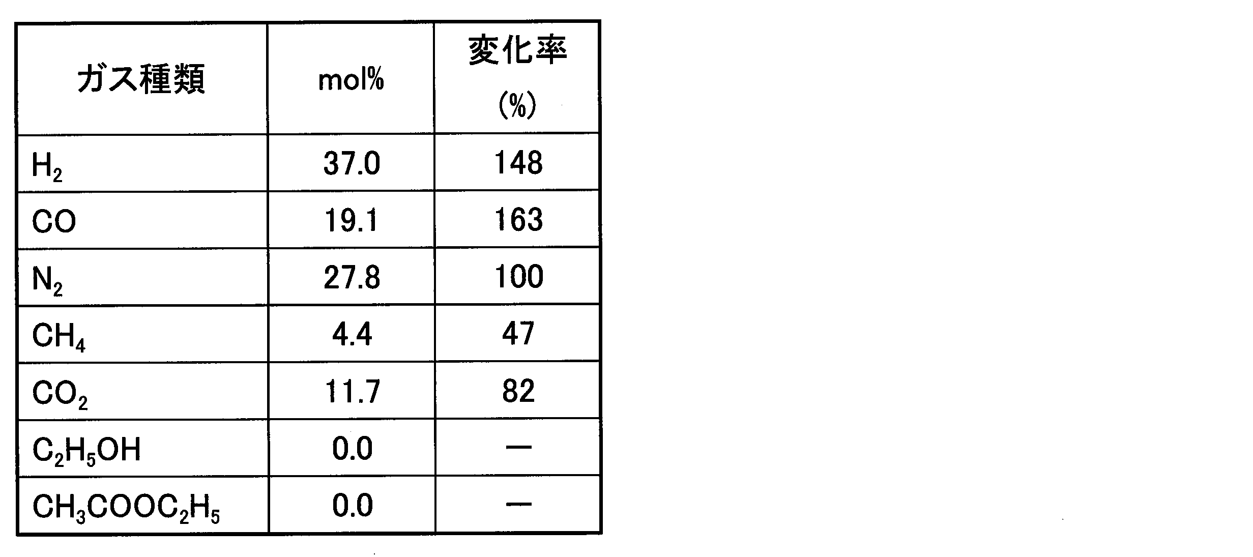
続いて、表5に示す組成の分離ガスを流量9.8NL/分で、流量2.5NL/分の水蒸気とともに改質器5に流通させながら、その反応床出口温度が770℃になるまで改質触媒を昇温し、温度を安定化させた。その後、出口ガスの組成をガスクロマトグラフィーにより分析した。この結果を表6に示す。また、表5の分離ガス組成である場合の760℃、1.0MPa(0.9MPaG)における平衡組成を算出した理論値を表7に示す。
メタン等の炭化水素を水蒸気改質するアルミナ担持ニッケル系触媒(主金属:NiO、かさ密度:0.9、形状:破砕状、粒子径:2~4mm)の177gを、内径29.9mm、長さ700mmのステンレス製の管に充填して改質器5とした。改質器5に0.3MPaGの圧力で水素を3NL/分と水蒸気3.6NL/分とを流通させ、150℃から760℃まで2℃/分の速度で昇温し、改質触媒に還元処理を施した。
続いて、表5に示す組成の分離ガスを流量9.8NL/分で、流量2.5NL/分の水蒸気とともに改質器5に流通させながら、その反応床出口温度が770℃になるまで改質触媒を昇温し、温度を安定化させた。その後、出口ガスの組成をガスクロマトグラフィーにより分析した。この結果を表6に示す。また、表5の分離ガス組成である場合の760℃、1.0MPa(0.9MPaG)における平衡組成を算出した理論値を表7に示す。
[実施例1の結果の評価]
改質器入口のガス組成(表5)と出口のガス組成(表6)を比較すると、メタンは10.9mol%から4.1mol%に減少し、水素は29.4mol%から38.5mol%へ増加し、COは13.8mol%から18.4mol%へ増加した。
改質器の目的は水素及びCOの濃度をそれぞれ増加させることであり、本実施例においては水素及びCO濃度をともに増加させることができた。この結果は、表7の平衡組成の計算値に近い良好な結果である。表5に示す通り、反応器1で生成したエタノールと酢酸エチル等の有機酸素化物を活性炭吸着塔4で分離したことにより、改質触媒が理論通りの優れた効率を安定的に発揮したことが明らかである。さらに、この条件では、CO2が16.7mol%から11.8mol%へ減少し、CO2の一部もCOに変換され、より有効に炭素源が利用できることが明らかである。
改質器入口のガス組成(表5)と出口のガス組成(表6)を比較すると、メタンは10.9mol%から4.1mol%に減少し、水素は29.4mol%から38.5mol%へ増加し、COは13.8mol%から18.4mol%へ増加した。
改質器の目的は水素及びCOの濃度をそれぞれ増加させることであり、本実施例においては水素及びCO濃度をともに増加させることができた。この結果は、表7の平衡組成の計算値に近い良好な結果である。表5に示す通り、反応器1で生成したエタノールと酢酸エチル等の有機酸素化物を活性炭吸着塔4で分離したことにより、改質触媒が理論通りの優れた効率を安定的に発揮したことが明らかである。さらに、この条件では、CO2が16.7mol%から11.8mol%へ減少し、CO2の一部もCOに変換され、より有効に炭素源が利用できることが明らかである。




[実施例2]
実施例1と同様のシステムを使用し、ほぼ同様の手順であるが、一部異なる下記の手順で有機酸素化物の製造を実施した。
手順1の詳細:反応床温度を240℃まで降温した後、表8の組成の混合ガスを3.5NL/分で流通させ、反応圧力を2.05MPaまで昇圧した。生成ガスは冷却器(冷媒温度5℃)で冷却された後、分離ガスとして導出した。反応温度を1℃/1分の速度で280~290℃まで昇温し、温度が安定した時を反応開始時とした。
また、手順1における反応開始時から約30分後に、系内を循環するガス中の炭化2.05MPaまで昇圧した。生成ガスは冷却器(冷媒温度5℃)で冷却された後、分離ガスとして導出した。反応温度を1℃/1分の速度で280~290℃まで昇温し、温度が安定した時を反応開始時とした。
手順2の詳細:バイパスラインへ分離ガスを導入しながら、ガスブースター(GB)で圧力を0.67MPaGから2.1MPaGまで昇圧した。マスフロー(MFC)でバイパスガス流量を増やしていき、17.5NL/分とした。このとき、バイパスラインから反応器1へ導入する分離ガスの量は、新たに導入する合成ガスと合わせて21NL/分とした。反応器1,2における反応温度が280~290℃になるように調整した。
水素の濃度が高まった頃に、手順3の改質工程を行った。
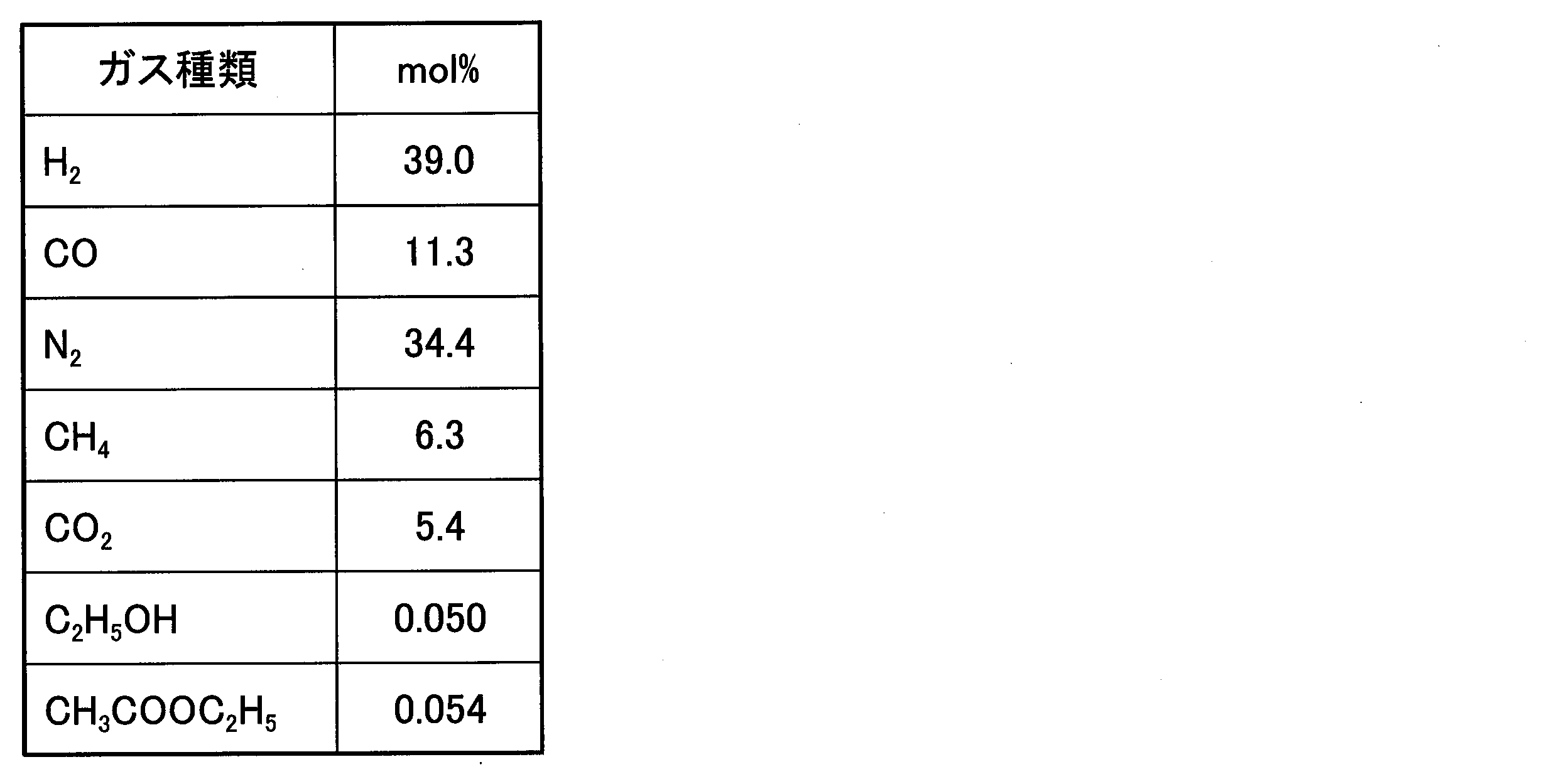
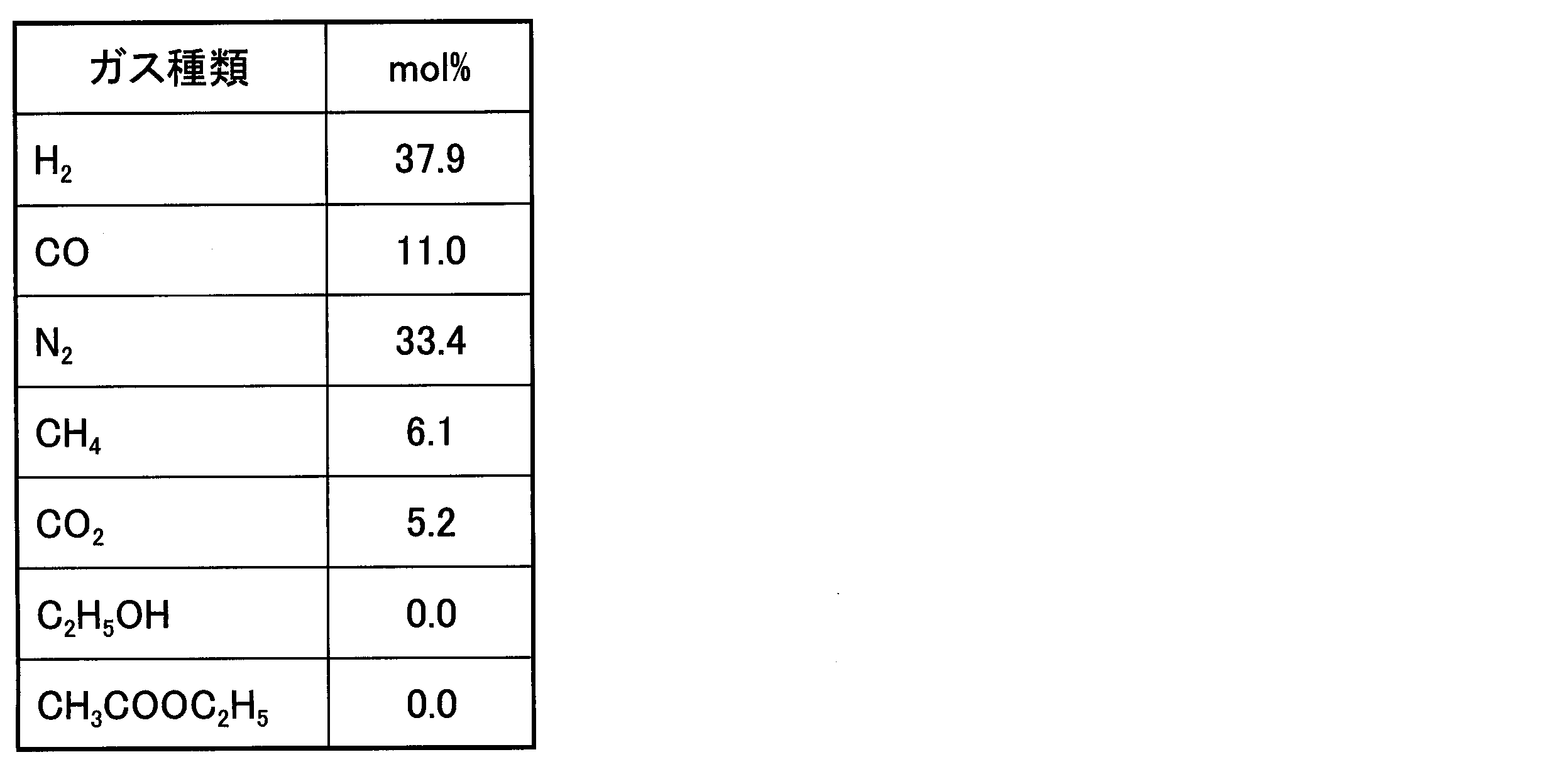
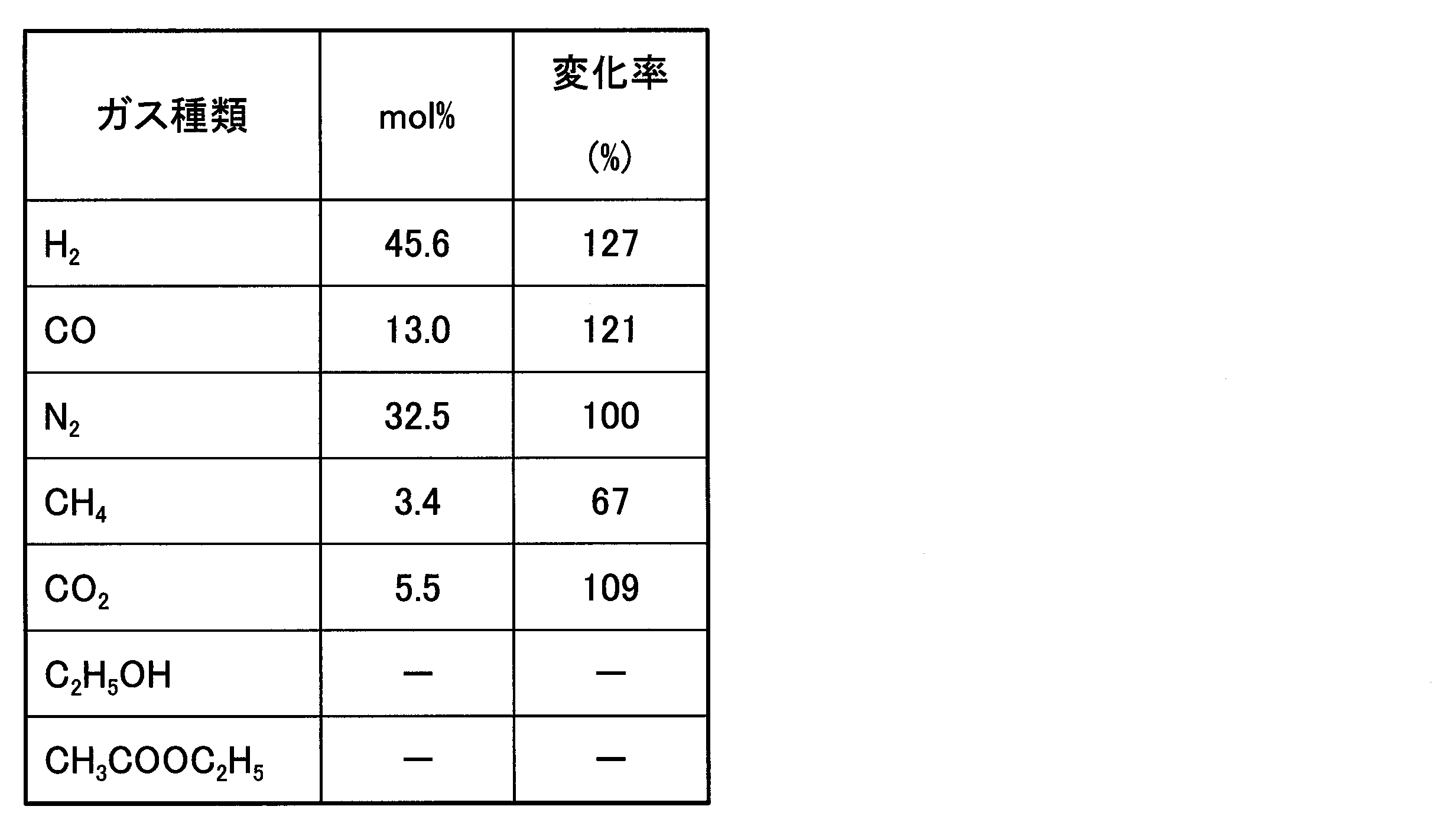
手順3の詳細:改質器5に水蒸気を流量3.7NL/分で流通し、出口温度が778℃になるように昇温し、温度が安定化した後、バイパスラインを流通する分離ガスを改質器5に流通させ、ガス流量を17.5NL/分まで増加させた。その後、改質反応床出口温度を778℃に安定化させた後、反応器1入口ガス組成を表9に、反応器2出口ガス組成を表10に、冷却器出口ガス組成を表11に、改質器入口ガス組成を表12に、改質出口ガス組成を表13に示す。
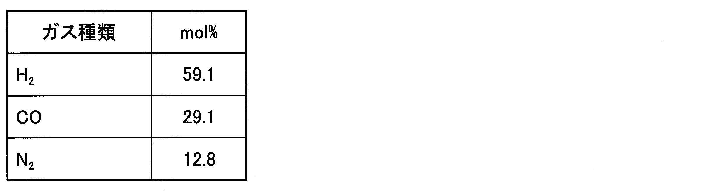
さらに、表12の分離ガス組成である場合の778℃、0.77MPa(0.67MPaG)における平衡組成を算出した理論値を表14に示す。
実施例1と同様のシステムを使用し、ほぼ同様の手順であるが、一部異なる下記の手順で有機酸素化物の製造を実施した。
手順1の詳細:反応床温度を240℃まで降温した後、表8の組成の混合ガスを3.5NL/分で流通させ、反応圧力を2.05MPaまで昇圧した。生成ガスは冷却器(冷媒温度5℃)で冷却された後、分離ガスとして導出した。反応温度を1℃/1分の速度で280~290℃まで昇温し、温度が安定した時を反応開始時とした。
また、手順1における反応開始時から約30分後に、系内を循環するガス中の炭化2.05MPaまで昇圧した。生成ガスは冷却器(冷媒温度5℃)で冷却された後、分離ガスとして導出した。反応温度を1℃/1分の速度で280~290℃まで昇温し、温度が安定した時を反応開始時とした。
手順2の詳細:バイパスラインへ分離ガスを導入しながら、ガスブースター(GB)で圧力を0.67MPaGから2.1MPaGまで昇圧した。マスフロー(MFC)でバイパスガス流量を増やしていき、17.5NL/分とした。このとき、バイパスラインから反応器1へ導入する分離ガスの量は、新たに導入する合成ガスと合わせて21NL/分とした。反応器1,2における反応温度が280~290℃になるように調整した。
水素の濃度が高まった頃に、手順3の改質工程を行った。
手順3の詳細:改質器5に水蒸気を流量3.7NL/分で流通し、出口温度が778℃になるように昇温し、温度が安定化した後、バイパスラインを流通する分離ガスを改質器5に流通させ、ガス流量を17.5NL/分まで増加させた。その後、改質反応床出口温度を778℃に安定化させた後、反応器1入口ガス組成を表9に、反応器2出口ガス組成を表10に、冷却器出口ガス組成を表11に、改質器入口ガス組成を表12に、改質出口ガス組成を表13に示す。
さらに、表12の分離ガス組成である場合の778℃、0.77MPa(0.67MPaG)における平衡組成を算出した理論値を表14に示す。



[実施例2の結果の評価]
改質器入口のガス組成(表12)と出口のガス組成(表13)を比較すると、メタンは6.1mol%から3.1mol%に減少し、水素は37.9mol%から45.6mol%へ増加し、COは11.0mol%から13.2mol%へ増加した。
改質器の目的は水素及びCOの濃度をそれぞれ増加させることであり、本実施例においては水素及びCO濃度をともに増加させることができた。この結果は、表14の平衡組成の計算値に近い良好な結果である。表11と表12に示す通り、反応器1で生成したエタノールと酢酸エチル等の有機酸素化物を活性炭吸着塔4で分離したことにより、改質触媒が理論通りの優れた効率を安定的に発揮したことが明らかである。
改質器入口のガス組成(表12)と出口のガス組成(表13)を比較すると、メタンは6.1mol%から3.1mol%に減少し、水素は37.9mol%から45.6mol%へ増加し、COは11.0mol%から13.2mol%へ増加した。
改質器の目的は水素及びCOの濃度をそれぞれ増加させることであり、本実施例においては水素及びCO濃度をともに増加させることができた。この結果は、表14の平衡組成の計算値に近い良好な結果である。表11と表12に示す通り、反応器1で生成したエタノールと酢酸エチル等の有機酸素化物を活性炭吸着塔4で分離したことにより、改質触媒が理論通りの優れた効率を安定的に発揮したことが明らかである。
本発明の有機酸素化物の製造方法及び製造システムによれば、合成ガスから有機酸素化物を生成した際に副生成物として生成される炭化水素を効率的に水素と一酸化炭素に改質することができる。また、本発明の炭化水素の改質方法によれば、炭化水素を効率的に水素と一酸化炭素に改質することができる。
1…反応器、2…反応器、3…冷却器、3a…デミスター、4…活性炭吸着塔、5…改質器、6…冷却器、10…製造システム
Claims (10)
- 炭化水素を含み、有機酸素化物の含有量がモル基準で1000ppm未満であるガスと、水蒸気とを改質触媒に接触させ、前記ガスに含まれる水素の濃度及び一酸化炭素の濃度よりも高い水素の濃度及び一酸化炭素の濃度を有する改質ガスを得る改質工程を有する、炭化水素の改質方法。
- 前記ガスを活性炭に接触させ、前記有機酸素化物の少なくとも一部を前記ガスから分離することにより、前記ガスに含まれる前記有機酸素化物の含有量をモル基準で1000ppm未満に低下させる分離工程を有する、請求項1に記載の炭化水素の改質方法。
- 水素及び一酸化炭素を含む合成ガスを合成触媒に接触させ、有機酸素化物及び炭化水素を含む生成ガスを得る生成工程と、
前記生成ガスから前記有機酸素化物の少なくとも一部を分離し、前記炭化水素を含む分離ガスを得る分離工程と、
前記分離ガスと、水蒸気とを改質触媒に接触させ、前記分離ガスに含まれる水素の濃度及び一酸化炭素の濃度よりも高い水素の濃度及び一酸化炭素の濃度を有する改質ガスを得る改質工程と、
を有する有機酸素化物の製造方法であって、
前記改質工程で用いる前記分離ガス中の前記有機酸素化物の含有量は、モル基準で1000ppm未満である、有機酸素化物の製造方法。 - 前記改質ガスを前記合成触媒に接触させ、前記生成ガスを得る再利用工程を有する、請求項3に記載の有機酸素化物の製造方法。
- 前記有機酸素化物が、エタノール及び酢酸エチルからなる群から選択される少なくとも1つである、請求項3又は4に記載の有機酸素化物の製造方法。
- 前記分離工程は、前記有機酸素化物を活性炭に吸着させる吸着処理を有する、請求項3~5の何れか一項に記載の有機酸素化物の製造方法。
- 前記活性炭に吸着した前記有機酸素化物を気化させて回収する回収処理を有する、請求項6に記載の有機酸素化物の製造方法。
- 水素及び一酸化炭素から有機酸素化物及び炭化水素を生成する合成触媒を備え、
水素及び一酸化炭素を含む合成ガスを導入すると、前記合成触媒の作用により、有機酸素化物及び炭化水素を含む生成ガスが生成される生成部と;
冷却器及び活性炭吸着器若しくはスクラバーを備え、
前記生成ガスを導入すると、前記冷却器及び前記活性炭吸着器若しくはスクラバーによって前記有機酸素化物の少なくとも一部が分離された分離ガスが得られる分離部と;
炭化水素及び水蒸気から一酸化炭素及び水素を生成する改質触媒を備え、
前記分離ガス及び水蒸気を導入すると、前記改質触媒の作用により、前記分離ガスに含まれる水素の濃度及び一酸化炭素の濃度よりも高い水素の濃度及び一酸化炭素の濃度を有する改質ガスが得られる改質部と;
を有する有機酸素化物の製造システム。 - 前記改質部で用いられる前記分離ガス中の前記有機酸素化物の含有量は、モル基準で1000ppm未満である、請求項8に記載の有機酸素化物の製造システム。
- 前記有機酸素化物が、エタノール及び酢酸エチルからなる群から選択される少なくとも1つである、請求項8又は9に記載の有機酸素化物の製造システム。
Priority Applications (1)
| Application Number | Priority Date | Filing Date | Title |
|---|---|---|---|
| JP2018517052A JPWO2017195817A1 (ja) | 2016-05-12 | 2017-05-10 | 炭化水素の改質方法、有機酸素化物の製造方法、及び有機酸素化物の製造システム |
Applications Claiming Priority (2)
| Application Number | Priority Date | Filing Date | Title |
|---|---|---|---|
| JP2016096161 | 2016-05-12 | ||
| JP2016-096161 | 2016-05-12 |
Publications (1)
| Publication Number | Publication Date |
|---|---|
| WO2017195817A1 true WO2017195817A1 (ja) | 2017-11-16 |
Family
ID=60267643
Family Applications (1)
| Application Number | Title | Priority Date | Filing Date |
|---|---|---|---|
| PCT/JP2017/017674 Ceased WO2017195817A1 (ja) | 2016-05-12 | 2017-05-10 | 炭化水素の改質方法、有機酸素化物の製造方法、及び有機酸素化物の製造システム |
Country Status (2)
| Country | Link |
|---|---|
| JP (1) | JPWO2017195817A1 (ja) |
| WO (1) | WO2017195817A1 (ja) |
Cited By (1)
| Publication number | Priority date | Publication date | Assignee | Title |
|---|---|---|---|---|
| JP2023019891A (ja) * | 2021-07-30 | 2023-02-09 | 三菱化工機株式会社 | 水素製造装置及び水素製造装置の運転方法 |
Citations (2)
| Publication number | Priority date | Publication date | Assignee | Title |
|---|---|---|---|---|
| JP2012025655A (ja) * | 2010-07-23 | 2012-02-09 | IFP Energies Nouvelles | 中間圧力でのパージによる水素製造方法 |
| JP2012149089A (ja) * | 2009-02-12 | 2012-08-09 | Ichikawa Office Inc | エタノールの製造方法 |
-
2017
- 2017-05-10 WO PCT/JP2017/017674 patent/WO2017195817A1/ja not_active Ceased
- 2017-05-10 JP JP2018517052A patent/JPWO2017195817A1/ja active Pending
Patent Citations (2)
| Publication number | Priority date | Publication date | Assignee | Title |
|---|---|---|---|---|
| JP2012149089A (ja) * | 2009-02-12 | 2012-08-09 | Ichikawa Office Inc | エタノールの製造方法 |
| JP2012025655A (ja) * | 2010-07-23 | 2012-02-09 | IFP Energies Nouvelles | 中間圧力でのパージによる水素製造方法 |
Non-Patent Citations (3)
| Title |
|---|
| "Effect Of Shale Plays On U.S. Natural Gas Composition", PIPELINE & GAS JOURNAL, vol. 241, no. 7, July 2014 (2014-07-01), pages 38 - 41 * |
| "LNG Shokibo Kichi (Gijutsu Guideline", THE JAPAN GAS ASSOCIATION, December 2000 (2000-12-01), pages 1 * |
| KAGAKU BINRAN (OYOHEN, 25 October 1965 (1965-10-25), pages 1072 * |
Cited By (2)
| Publication number | Priority date | Publication date | Assignee | Title |
|---|---|---|---|---|
| JP2023019891A (ja) * | 2021-07-30 | 2023-02-09 | 三菱化工機株式会社 | 水素製造装置及び水素製造装置の運転方法 |
| JP7695142B2 (ja) | 2021-07-30 | 2025-06-18 | 三菱化工機株式会社 | 水素製造装置及び水素製造装置の運転方法 |
Also Published As
| Publication number | Publication date |
|---|---|
| JPWO2017195817A1 (ja) | 2019-03-14 |
Similar Documents
| Publication | Publication Date | Title |
|---|---|---|
| JP5411133B2 (ja) | 二酸化炭素の合成ガスへの接触水素化 | |
| US6800665B1 (en) | Method for producing dimethyl ether | |
| US6562306B1 (en) | Apparatus for producing dimethyl ether | |
| JP5424569B2 (ja) | 天然ガスからの液状炭化水素製造プロセスにおける合成ガスの製造方法 | |
| US20160129423A1 (en) | Supported iron catalysts, methods of making, methods of hydrocarbon decomposition | |
| Hu et al. | Hydrogen production by sorption-enhanced steam reforming of acetic acid over Ni/CexZr1− xO2-CaO catalysts | |
| Morales-Marín et al. | Biohydrogen production by glycerol Aqueous-Phase Reforming: Effect of promoters (Ce or Mg) in the NiAl2O4 spinel-derived catalysts | |
| JP6698534B2 (ja) | ブタジエンの製造方法及びブタジエン製造装置 | |
| EA015474B1 (ru) | Получение катализаторов синтеза фишера-тропша | |
| TWI675823B (zh) | 丙烷之製造方法及丙烷製造裝置 | |
| EA008740B1 (ru) | Способ селективного окисления сероводорода | |
| JP2012219068A (ja) | 高効率メタノール製造方法 | |
| WO2017085603A2 (en) | Methods for the conversion of co2 into syngas for use in the production of olefins | |
| KR101600139B1 (ko) | 천연가스를 이용한 경질 올레핀의 제조 방법 | |
| CN103459018A (zh) | 被活性化的费-托合成反应用催化剂及烃的制造方法 | |
| JP7788153B2 (ja) | 低濃度域を含む濃度の二酸化炭素から炭化水素化合物を製造する方法 | |
| JPWO2017195817A1 (ja) | 炭化水素の改質方法、有機酸素化物の製造方法、及び有機酸素化物の製造システム | |
| JP5738743B2 (ja) | メタノールプラントを利用した酢酸原料又はmma原料の製造方法 | |
| JP2017202459A (ja) | ガス分離方法、有機酸素化物の製造方法、ガス分離装置、及び有機酸素化物の製造システム | |
| JP5906913B2 (ja) | 低級オレフィンの製造方法 | |
| WO2020059889A1 (ja) | 触媒、及びこれを用いた1,3-ブタジエンの製造方法 | |
| Avruscio et al. | Enhancing dimethyl ether production as a renewable fuel using a high-performance BEA zeolite membrane reactor | |
| CN103764278A (zh) | C2氧化物合成用催化剂、c2氧化物的制造装置及c2氧化物的制造方法 | |
| BR102016017273A2 (pt) | processo para a preparação de um catalisador pretendido para uso em uma reação de fischer-tropsch | |
| WO2018020345A1 (en) | Process for producing oxo-synthesis syngas composition by high-pressure hydrogenation of c02 over spent chromium oxide/aluminum catalyst |
Legal Events
| Date | Code | Title | Description |
|---|---|---|---|
| ENP | Entry into the national phase |
Ref document number: 2018517052 Country of ref document: JP Kind code of ref document: A |
|
| NENP | Non-entry into the national phase |
Ref country code: DE |
|
| 121 | Ep: the epo has been informed by wipo that ep was designated in this application |
Ref document number: 17796177 Country of ref document: EP Kind code of ref document: A1 |
|
| 122 | Ep: pct application non-entry in european phase |
Ref document number: 17796177 Country of ref document: EP Kind code of ref document: A1 |