WO2017195761A1 - 送信機および受信機 - Google Patents
送信機および受信機 Download PDFInfo
- Publication number
- WO2017195761A1 WO2017195761A1 PCT/JP2017/017487 JP2017017487W WO2017195761A1 WO 2017195761 A1 WO2017195761 A1 WO 2017195761A1 JP 2017017487 W JP2017017487 W JP 2017017487W WO 2017195761 A1 WO2017195761 A1 WO 2017195761A1
- Authority
- WO
- WIPO (PCT)
- Prior art keywords
- radio wave
- information signal
- orthogonal code
- transmitter
- orthogonal
- Prior art date
Links
Images


Classifications
-
- H—ELECTRICITY
- H04—ELECTRIC COMMUNICATION TECHNIQUE
- H04B—TRANSMISSION
- H04B7/00—Radio transmission systems, i.e. using radiation field
- H04B7/02—Diversity systems; Multi-antenna system, i.e. transmission or reception using multiple antennas
- H04B7/10—Polarisation diversity; Directional diversity
-
- H—ELECTRICITY
- H04—ELECTRIC COMMUNICATION TECHNIQUE
- H04B—TRANSMISSION
- H04B7/00—Radio transmission systems, i.e. using radiation field
- H04B7/02—Diversity systems; Multi-antenna system, i.e. transmission or reception using multiple antennas
- H04B7/04—Diversity systems; Multi-antenna system, i.e. transmission or reception using multiple antennas using two or more spaced independent antennas
- H04B7/06—Diversity systems; Multi-antenna system, i.e. transmission or reception using multiple antennas using two or more spaced independent antennas at the transmitting station
-
- H—ELECTRICITY
- H04—ELECTRIC COMMUNICATION TECHNIQUE
- H04J—MULTIPLEX COMMUNICATION
- H04J11/00—Orthogonal multiplex systems, e.g. using WALSH codes
-
- H—ELECTRICITY
- H04—ELECTRIC COMMUNICATION TECHNIQUE
- H04J—MULTIPLEX COMMUNICATION
- H04J13/00—Code division multiplex systems
- H04J13/0003—Code application, i.e. aspects relating to how codes are applied to form multiplexed channels
-
- H—ELECTRICITY
- H04—ELECTRIC COMMUNICATION TECHNIQUE
- H04J—MULTIPLEX COMMUNICATION
- H04J13/00—Code division multiplex systems
- H04J13/0007—Code type
- H04J13/004—Orthogonal
-
- H—ELECTRICITY
- H04—ELECTRIC COMMUNICATION TECHNIQUE
- H04J—MULTIPLEX COMMUNICATION
- H04J13/00—Code division multiplex systems
- H04J13/16—Code allocation
- H04J13/18—Allocation of orthogonal codes
Definitions
- the present invention relates to a transmitter and a receiver.
- a radio wave scatterer that reflects and diffracts electromagnetic waves exists between a transmitter and a receiver that perform wireless communication
- a plurality of wireless propagation paths are formed between the two devices. If these plurality of wireless propagation paths are simply used collectively, wireless communication is hindered when any of the propagation paths is affected naturally or artificially and modified. Therefore, it is desirable if the correlation of a plurality of radio propagation paths can be suppressed.
- Patent Document 1 states, “According to the present invention, regarding the demodulation method of MIMO-OFDM transmission using a plurality of transmission antennas and reception antennas, different polarizations such as orthogonal polarization are transmitted and received in an outdoor line-of-sight environment.
- the cross-polarization power ratio measured on the receiving side is used to adjust the XPD of each transmitting antenna on the transmitting side and the receiving side, thereby making the correlation of each propagation path efficient.
- a transmitter includes a first transmission unit that modulates an information signal and generates a first radio wave whose polarization plane rotates, and a first polarization unit that modulates the information signal and has a fixed polarization plane. And a second transmitter that generates two radio waves.
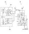
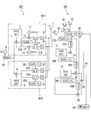
- 1 is a block diagram of a wireless communication system according to a first embodiment of the present invention. It is a block diagram of the radio
- FIG. 1 is a block diagram of a radio communication system according to a first embodiment of the present invention.
- the wireless communication system according to the present embodiment includes a transmitter 201 and a receiver 301.
- the transmitter 201 includes transmitting antennas 1 and 2 that are spatially orthogonal. For example, if the polarization plane of the transmission antenna 1 is vertical (V), the polarization plane of the transmission antenna 2 is horizontal (H).
- the transmitter 201 includes an information signal generator 4, a transmission unit 2011 (first transmission unit), and a transmission unit 2012 (second transmission unit).
- the information signal generator 4 outputs an information signal having an angular frequency ⁇ I to be transmitted to the receiver 301.
- the transmission units 2011 and 2012 modulate the information signal to generate a radio frequency band transmission signal, and supply the generated transmission signal to the transmission antennas 1 and 2.
- an orthogonal code generation circuit (indicated as OCG in the figure, hereinafter the same) 5 outputs an orthogonal code # 1 (first orthogonal code), which is a spreading code, and a multiplier 7 (first superimposition code). Circuit) multiplies the orthogonal code # 1 and the information signal, and spreads the information signal with the orthogonal code # 1.
- orthogonal code # 1 first orthogonal code
- the term “rotational polarization” used in the following description will be described.
- As the polarization of electromagnetic waves linearly polarized waves and circularly polarized waves are known.
- a plane including the direction of vibration of the electric field and the propagation direction of the electromagnetic wave is referred to as a polarization plane.
- circularly polarized light is one whose plane of polarization rotates.
- “Rotational polarization” is a type of circular polarization, but refers to the one whose rotational frequency of the polarization plane is lower than the frequency of the carrier wave of electromagnetic waves.
- the polarization rotation frequency cosine oscillator 11 (oscillator for polarization plane rotation) is cos ⁇ p. t is output, and the polarization rotation frequency sine oscillator 12 (polarization plane rotation oscillator) outputs sin ⁇ p t.
- the multiplier 13 multiplies the output signal and a cos .omega p t of the multiplier 7, the multiplier 14 multiplies the output signal and the sin .omega p t multiplier 7.
- the carrier frequency cosine oscillator 19 (carrier oscillator) outputs cos ⁇ c t when the carrier frequency is ⁇ c (carrier frequency, where ⁇ c > ⁇ p ).
- the multiplier 17 multiplies the output signal of the multiplier 13 by cos ⁇ c t and supplies the multiplication result to the transmission antenna 1.
- the multiplier 18 multiplies the output signal of the multiplier 14 by cos ⁇ c t and supplies the multiplication result to the transmission antenna 2.
- An electromagnetic wave transmitted from the transmission unit 2011 via the transmission antennas 1 and 2 becomes a rotationally polarized electromagnetic wave having a rotational angular frequency ⁇ p and propagates an information signal spread by the orthogonal code # 1.
- the orthogonal code generation circuit 6 outputs an orthogonal code # 2 (second orthogonal code) that is a spreading code
- the multiplier 8 (second superposition circuit) outputs the orthogonal code # 2 and the orthogonal code # 2. Multiply by the information signal.
- the orthogonal code # 2 is a code orthogonal to the orthogonal code # 1 described above.
- the carrier frequency cosine oscillator 21 outputs cos ( ⁇ c ⁇ p ) t
- the carrier frequency cosine oscillator 22 outputs cos ( ⁇ c + ⁇ p ) t.
- the multiplier 23 multiplies the output signal of the multiplier 8 by cos ( ⁇ c ⁇ p ) t.
- the multiplication result is supplied to the transmission antenna 1 as a transmission signal having a carrier angular frequency of ⁇ c ⁇ p .
- the multiplier 24 multiplies the output signal of the multiplier 8 by cos ( ⁇ c + ⁇ p ) t.
- the multiplication result is supplied to the transmission antenna 2 as a transmission signal having a carrier angular frequency of ⁇ c + ⁇ p .
- the electromagnetic waves transmitted from the transmission unit 2012 via the transmission antennas 1 and 2 are both linearly polarized electromagnetic waves whose polarization planes are fixed, and propagate the information signal spread by the orthogonal code # 2.
- the receiver 301 has spatially orthogonal receiving antennas 61 and 62 in order to receive the electromagnetic waves transmitted from the transmitter 201. For example, if the polarization plane of the reception antenna 61 is vertical (V), the polarization plane of the reception antenna 62 is horizontal (H).
- the multiplier 73 (first receiving unit) multiplies the received signal of the receiving antenna 61 by cos ⁇ c t output from the carrier frequency cosine oscillator 72.
- the multiplier 74 (first despreading unit) multiplies the orthogonal code # 1 output from the orthogonal code generation circuit 71 (first despreading unit) and the output signal of the multiplier 73.
- the electromagnetic wave having the carrier angular frequency ⁇ c is demodulated, and the demodulation result is despread in the multiplier 74.
- the electromagnetic wave having the carrier angular frequency ⁇ c is an electromagnetic wave generated by the transmission unit 2011 and rotated and polarized via the transmission antennas 1 and 2.
- the reception antenna 61 cannot receive this rotationally polarized electromagnetic wave, and the output signals of the multipliers 73 and 74 are It becomes almost zero.
- this timing appears in synchronization with the rotation period of the rotational polarization, it can be expressed as “the angle of the polarization plane of the rotational polarization”.
- this angle is referred to as “non-detection angle ⁇ z ”.
- the output signal of the multiplier 74, except the timing of the non-detection angle theta z, ideally, equal to the original information signal information signal generator 4 in the transmitter 201 is output.
- the carrier frequency cosine oscillator 82 outputs cos ( ⁇ c ⁇ p ) t
- the multiplier 83 receives cos ( ⁇ c ⁇ p ) t and the reception signal of the receiving antenna 61.
- Multiply Multiplier 84 (second despreading unit) multiplies orthogonal code # 2 output from orthogonal code generation circuit 81 (second despreading unit) by the output signal of multiplier 83.
- the received signal of the carrier angular frequency ⁇ c ⁇ p received by the receiving antenna 61 is demodulated and despread through the multipliers 83 and 84.
- the carrier frequency cosine oscillator 86 outputs cos ( ⁇ c + ⁇ p ) t, and the multiplier 87 (second receiver) multiplies cos ( ⁇ c + ⁇ p ) t by the reception signal of the receiving antenna 62.
- Multiplier 88 (second despreading unit) multiplies orthogonal code # 2 output from orthogonal code generation circuit 81 and the output signal of multiplier 87.
- the received signal of the carrier angular frequency ⁇ c + ⁇ p received by the receiving antenna 62 is demodulated and despread through the multipliers 87 and 88.
- the adder 64 combines the signals output from the multipliers 84 and 88. Therefore, the synthesized signal is ideally equal to the information signal originally output from the information signal generator 4 in the transmitter 201.
- the electromagnetic wave of the carrier angular frequency ⁇ c + ⁇ p and the electromagnetic wave of the carrier angular frequency ⁇ c ⁇ p whose polarization plane is fixed propagate the same information signal at different carrier angular frequencies and different polarization planes. is there. Therefore, the adder 64 can continue to output an information signal with a substantially constant intensity by individually demodulating and despreading these electromagnetic waves and then synthesizing them.
- the subtracter 65 subtracts the output signal of the multiplier 74 from the output signal of the adder 64 and outputs the subtraction result.
- the output signal of the multiplier 74 is ideally the original information signal. Therefore, except for the non-detection angle ⁇ z , ideally, the output signal of the subtractor 65 has a zero value.
- the output signal of the multiplier 74 becomes almost zero, so ideally, the original information signal at the non-detection angle ⁇ z is output from the subtractor 65.
- the subtracter 65 in the non-detection angle receives the information signal and performs processing based on the information signal.
- the non-detection angle ⁇ z is not limited to one, and a plurality of non-detection angles ⁇ z are generated when there are a plurality of wireless propagation paths. These non-detection angles are assumed to be ⁇ z1 , ⁇ z2 ,.
- the subtractor 65 outputs an information signal for each of these non-detection angles ⁇ z1 , ⁇ z2 ,.
- the baseband unit 66 separates the information signal according to the non-detection angles ⁇ z1 , ⁇ z2 ,..., ⁇ zn , and any specific non-detection angle ⁇ zm (where 1 ⁇ m ⁇ n). The processing based on the information signal is performed.
- the electromagnetic wave transmitted from the transmitter 201 is reflected by various radio wave scatterers before reaching the receiver 301.
- the surface of the radio wave scatterer satisfies Snell's reflection law
- the electromagnetic wave is reflected by the surface of the radio wave scatterer, the normal vector of the surface of the radio wave scatterer and the surface of the electromagnetic wave
- the polarization vector inherent in the incident vector is shifted.
- the electromagnetic wave reaches the receiver 301 via a plurality of wireless propagation paths that have undergone the polarization vector shift.
- Each radio propagation path generally undergoes a different inherent polarization shift.
- the receiver 301 in this embodiment can extract only a signal transmitted by an electromagnetic wave having a specific polarization (that is, an electromagnetic wave having a specific non-detection angle ⁇ zm ). This is equivalent to capturing only an information signal that has reached the receiver 301 via a specific wireless propagation path.
- information signals propagated through a plurality of wireless propagation paths are separated on the time axis according to the non-detection angles ⁇ z1 , ⁇ z2 ,. Only the information signal at the non-detection angle ⁇ zm can be captured. That is, an information signal can be transmitted by selecting a specific wireless propagation path from among a plurality of wireless propagation paths. Thereby, the correlation of a some radio propagation path is suppressed, it can have the strong tolerance with respect to the failure and disturbance of an artificial or natural radio propagation path, and appropriate communication can be implement
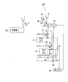
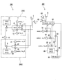
- FIG. 2 is a block diagram of a radio communication system according to the second embodiment of the present invention.
- the wireless communication system according to the present embodiment includes a transmitter 201 and a receiver 302.
- the configuration of the transmitter 201 is the same as that of the first embodiment (see FIG. 1), the configuration of the receiver 302 will be described in detail.
- the receiver 302 has three receiving antennas 61, 62, and 63 that are spatially orthogonal to each other, and these three systems of received signals are supplied to the polarization rotation circuit 60.
- the polarization rotation circuit 60 converts the received three systems of received signals into two systems of pseudo received signals (V ′, H ′) that are spatially orthogonal to each other and outputs the converted signals.
- the polarization rotation circuit 60 performs angle weighting on the three systems of received signals from the receiving antennas 61, 62, and 63 and converts them into two systems of pseudo received signals (V ′, H ′).
- the angular weight is, for example, an Euler angle, and is an angular weight that virtually forms two linearly polarized antennas in a three-dimensional space by receiving antennas 61, 62, and 63 that are spatially orthogonal to each other. That is, the polarization rotation circuit 60 operates so that the receiver 302 virtually forms two antennas that are spatially orthogonal in an arbitrary direction.
- the pseudo reception signal (V ′, H ′) output from the polarization rotation circuit 60 is supplied to the multipliers 73 and 83, and the pseudo reception signal (H ′) is supplied to the multiplier 87.
- the configuration from the multipliers 73, 83, 87 to the subtracter 65 is the same as that of the first embodiment (see FIG. 1).
- the baseband unit 66 separates information signals according to the non-detection angles ⁇ z1 , ⁇ z2 ,..., ⁇ zn , and any specific non-detection angle ⁇ zm ( However, processing based on the information signal in 1 ⁇ m ⁇ n) is performed.
- the baseband unit 66 controls the angle weight of the polarization rotation circuit 60 so that the information signal output from the subtracter 65 has a good communication quality at the specific non-detection angle ⁇ zm .
- a plurality of rotationally polarized electromagnetic waves arriving at the receiver 302 via a plurality of wireless propagation paths are combined.
- the synthesized electromagnetic wave has one propagation direction and becomes an electromagnetic wave that rotates elliptically at the same frequency as the rotational polarization frequency.
- the reception intensity of the rotation polarization of the receiver 302 becomes zero.
- the reception intensity of the rotational polarization of the receiver 302 is maximized.
- the baseband unit 66 sets the angle weighting so that the intensity of the received signals from the virtually formed two antennas is as large as possible (ideally maximum), and the polarization rotation circuit 60 is operated.
- the receiver 302 of the present embodiment it is possible to improve the reception sensitivity with respect to a specific radio propagation path, so that the quality of the restored information signal is higher than the receiver 301 of the first embodiment. Can be improved.
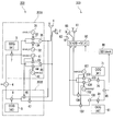
- FIG. 3 is a block diagram of a radio communication system according to the third embodiment of the present invention.
- the wireless communication system according to the present embodiment includes a transmitter 203 and a receiver 303.
- the transmitter 203 includes two transmission units 2031 and 2032 that supply the information signal supplied from the information signal generator 4 to the transmission antennas 1 and 2.
- ⁇ Transmitter 203> In the transmission unit 2031 of the transmitter 203, the information signal output from the information signal generator 4 is spread by the multiplier 7 with the orthogonal code # 1.
- the carrier frequency sine oscillator 31 (first sine oscillator) outputs sin ⁇ 1 t
- the carrier frequency sine oscillator 32 (second sine oscillator) outputs sin ⁇ 2 t.
- the angular frequency ⁇ 1 (carrier frequency, first frequency) and the angular frequency ⁇ 2 (carrier frequency, second frequency) are close to each other (for example, ⁇ 1 is within ⁇ 10% of ⁇ 2 ).
- the angular frequency of the carrier wave is close to each other (for example, ⁇ 1 is within ⁇ 10% of ⁇ 2 ).
- the multiplier 33 multiplies the output signal of the multiplier 7 by sin ⁇ 1 t
- the multiplier 34 multiplies the output signal of the multiplier 7 by sin ⁇ 2 t.
- the subtracter 35 subtracts the output signal of the multiplier 34 from the output signal of the multiplier 33 and supplies the subtraction result to the transmission antenna 1.
- the electromagnetic wave transmitted from the transmission antenna 1 by the transmission unit 2031 becomes a sine beat wave having a beat angular frequency that is half of the difference between the two angular frequencies ⁇ 1 and ⁇ 2 .
- the carrier frequency cosine oscillator 41 (first cosine oscillator) outputs cos ⁇ 1 t
- the carrier frequency cosine oscillator 42 (second cosine oscillator) outputs cos ⁇ 2 t.
- the multiplier 43 multiplies the output signal of the multiplier 7 by cos ⁇ 1 t
- the multiplier 44 multiplies the output signal of the multiplier 7 by cos ⁇ 2 t.
- the adder 45 adds the output signals of the multipliers 43 and 44 and supplies the addition result to the transmission antenna 2.
- the electromagnetic wave transmitted from the transmission antenna 2 by the transmission unit 2031 becomes a cosine beat wave having a beat angular frequency that is a half of the difference between the two angular frequencies ⁇ 1 and ⁇ 2 .
- the information signal output from the information signal generator 4 is spread by the multiplier 8 with the orthogonal code # 2.
- the multiplier 46 multiplies the output signal of the multiplier 8 by cos ⁇ 1 t and supplies the multiplication result to the transmission antenna 1.
- the multiplier 47 multiplies the output signal of the multiplier 8 by cos ⁇ 2 t, and supplies the multiplication result to the transmission antenna 2.
- the electromagnetic waves transmitted from the transmission unit 2032 via the transmission antennas 1 and 2 are both linearly polarized electromagnetic waves whose polarization plane is fixed, and propagate the information signal spread by the orthogonal code # 2.
- the receiver 303 includes three receiving antennas 61, 62, and 63 that are spatially orthogonal to each other and three from the receiving antennas 61, 62, and 63.
- a polarization rotation circuit 60 that performs angle weighting on the received signals of the system, virtually forms two spatially orthogonal antennas, and converts them into two systems of pseudo received signals.
- the multiplier 103 multiplies one generated pseudo reception signal (V ′) by cos ⁇ 1 t output from the carrier frequency cosine oscillator 101.
- the multiplier 104 multiplies the one pseudo reception signal (V ′) by cos ⁇ 2 t output from the carrier frequency cosine oscillator 102.
- Adder 105 adds the multiplication results of multipliers 103 and 104.
- the multiplier 74 multiplies the output signal of the adder 105 by the orthogonal code # 1 output from the orthogonal code generation circuit 71. Thereby, the information signal spread by the orthogonal code # 1 is demodulated and despread.
- the two systems of pseudo received signals output from the polarization rotation circuit 60 are supplied to the multiplier 106 and the multiplier 107.
- the multiplier 106 multiplies one pseudo received signal (H ′) and cos ⁇ 1 t
- the multiplier 107 multiplies the other pseudo received signal (V ′) and cos ⁇ 2 t.
- the adder 108 adds the output signals of the multipliers 106 and 107
- the multiplier 84 multiplies the addition result by the orthogonal code # 2 output from the orthogonal code generation circuit 81. Thereby, the information signal spread by the orthogonal code # 2 is demodulated and despread.
- the subtractor 65 (restoring unit) subtracts the output signal of the multiplier 84 from the output signal of the multiplier 74.
- the subtractor 65 outputs an information signal for each of the non-detection angles ⁇ z1 , ⁇ z2 ,.
- the function of the baseband unit 66 is the same as that of the second embodiment. That is, the baseband unit 66 separates information signals according to the non-detection angles ⁇ z1 , ⁇ z2 ,..., ⁇ zn , and information at any specific non-detection angle ⁇ zm (where 1 ⁇ m ⁇ n). Perform processing based on the signal. Furthermore, the baseband unit 66 controls the angle weight of the polarization rotation circuit 60 so that the information signal output from the subtracter 65 exhibits good communication quality at the non-detection angle ⁇ zm .
- the angular frequencies ⁇ 1 and ⁇ 2 that are close to each other are used.
- Many elements included in the receiver 303 can be easily realized by a DSP (Digital Signal Processor) or the like. Thereby, the transmitter 203 and the receiver 303 can be reduced in size, and the secular change and temperature change of a circuit element can be suppressed, so that high reliability and long life of the apparatus can be realized.
- DSP Digital Signal Processor
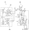
- FIG. 4 is a block diagram of a radio communication system according to the fourth embodiment of the present invention.
- the wireless communication system according to the present embodiment includes a transmitter 204 and a receiver 304.
- the transmitter 204 includes two transmission units 2011 and 2042 that supply the information signals supplied from the information signal generator 4 to the transmission antennas 1 and 2.
- the transmission unit 2011 is the same as that of the first embodiment (see FIG. 1). That is, the transmitting unit 2011 spreads the information signal with the orthogonal code # 1, and outputs the rotationally polarized electromagnetic wave having the carrier angular frequency ⁇ c and the rotational angular frequency ⁇ p via the transmitting antennas 1 and 2. To do.
- the information signal output from the information signal generator 4 is spread by the multiplier 8 with the orthogonal code # 2.
- Carrier frequency cosine oscillator 121 outputs a cos .omega c t
- a carrier frequency sinusoidal oscillator 122 outputs a sin .omega c t.
- the multiplier 23 multiplies the output signal of the multiplier 8 by cos ⁇ c t.
- the multiplier 24 multiplies the output signal of the multiplier 8 by sin ⁇ c t.
- the output signals of the multipliers 23 and 24 are supplied to the transmission antennas 1 and 2, respectively. Accordingly, the transmission unit 2042, using the cosine wave cos .omega c t, a sine wave sin .omega c t, via the transmitting antennas 1 and 2, it will send an electromagnetic wave temporally orthogonal. These electromagnetic waves are all linearly polarized electromagnetic waves whose polarization plane is fixed, and propagate information signals diffused by orthogonal code # 2.
- the configuration of the receiver 304 is different from the receiver 302 (see FIG. 2) of the second embodiment in that a carrier frequency cosine oscillator 182 is provided instead of the carrier frequency cosine oscillator 82 and the carrier frequency cosine oscillator 86 is replaced.
- a carrier frequency sine oscillator 186 is provided.
- Carrier frequency cosine oscillator 182 outputs a cos .omega c t
- a carrier frequency sinusoidal oscillator 186 outputs a sin .omega c t.
- the configuration of the receiver 304 is the same as that of the receiver 302.
- the plane of polarization is fixed, and the same information signal is transmitted from the transmitter 204 to the receiver 304 by two electromagnetic waves orthogonal in time. Then, after demodulating and despreading these two electromagnetic waves individually, the information signal is synthesized through the multipliers 84 and 88 and the adder 64, so that the adder 64 has the information signal at a substantially constant intensity. Can continue to output.
- the multiplier 74 outputs an information signal having a zero value at the non-detection angles ⁇ z1 , ⁇ z2 ,. Therefore, the subtractor 65 outputs an information signal for each of these non-detection angles ⁇ z1 , ⁇ z2 ,.
- the baseband unit 66 performs processing based on the information signal at any specific non-detection angle ⁇ zm , and the angle of the polarization rotation circuit 60 so that the information signal at the non-detection angle ⁇ zm exhibits good communication quality. Control the weight.
- the number of carrier frequencies to be used can be reduced as compared with the first to third embodiments, so that the amount of spurious signals caused by the nonlinearity of each part of the transmitter 204 can be reduced, and wireless communication Quality can be improved.
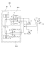
- FIG. 5 is a block diagram of a wireless communication system according to a fifth embodiment of the present invention.
- the wireless communication system according to the present embodiment includes a transmitter 205 and a receiver (not shown).
- the receiver any one of the receivers 301 and 302 (see FIGS. 1 and 2) in the first and second embodiments may be applied.
- the transmitter 205 is the same as the transmitter 201 of the first embodiment (see FIG. 1) in that it includes transmission units 2011 and 2012, transmission antennas 1 and 2, and an information signal generator 4. Further, the transmitter 205 includes a synchronization signal generation circuit (denoted as SCG in the drawing) 9 and a signal switching circuit 27.
- the synchronization signal generation circuit 9 outputs a predetermined synchronization signal.
- the signal switching circuit 27 selects one of the information signal output from the information signal generator 4 or the synchronization signal output from the synchronization signal generation circuit 9 every fixed period or every indefinite period, and transmits the selected signal to the transmission unit To both 2011 and 2012.
- the synchronization signal generated by the synchronization signal generation circuit 9 has a strong correlation characteristic, and by synchronizing the signal with a receiver, synchronization between the transmitter and the receiver can be accurately obtained. Since the polarization of the rotational polarization changes with time, when the synchronization between the transmitter and the receiver can be accurately taken, the degree of discrimination of the polarization in the receiver can be improved. A plurality of incoming waves arriving at the receiver undergo inherent polarization shifts through different propagation paths. According to this embodiment, the receiver can improve the identification accuracy based on the polarization of a plurality of incoming waves, and can improve the identification accuracy of the propagation path between the transceivers. Therefore, according to the present embodiment, there is an effect of improving the resistance to modification of the wireless propagation path by an outsider.
- FIG. 6 is a block diagram of a radio communication system according to the sixth embodiment of the present invention.
- the wireless communication system according to the present embodiment includes a transmitter 203 (see FIG. 3) and a receiver 306.
- the transmitter 203 is not shown in FIG.
- the receiver 306 includes three receiving antennas 61, 62, and 63 that are spatially orthogonal to each other, and three receiving units 3061, 3062, and 3063 that process the received signals of the receiving antennas 61, 62, and 63, respectively. is doing.
- the cosine oscillator 141 and 151 respectively outputs cos ⁇ 1 t, cos ⁇ 2 t, sine oscillator 145 and 155, respectively outputs the sin ⁇ 1 t, sin ⁇ 2 t.
- the orthogonal code generation circuits 142 and 146 output the orthogonal code # 1, and the orthogonal code generation circuits 152 and 156 output the orthogonal code # 2.
- Received signal of the receiving antenna 61 is 4 branches, in multiplier 143,147,153,157, respectively cos ⁇ 1 t, sin ⁇ 1 t, cos ⁇ 2 t, is multiplied by sin .omega 2 t.
- Multipliers 144 and 148 respectively multiply the output signals of multipliers 143 and 147 and orthogonal code # 1 to reproduce the information signal.
- Multipliers 154 and 158 respectively multiply the output signals of multipliers 153 and 157 and orthogonal code # 2 to reproduce the information signals. In this way, four systems of information signals are generated from the multipliers 144, 148, 154, and 158, and these information signals are supplied to the arithmetic unit 50.
- the receiving unit 3062 includes a cosine oscillator 241 and 251, a sine oscillator 245 and 255, multipliers 243, 244, 247, 248, 253, 254, 257 and 258, an orthogonal code generation circuit 242 that outputs an orthogonal code # 1. And orthogonal code generation circuits 252 and 256 for outputting orthogonal code # 2.
- These are the cosine oscillators 141 and 151, the sine oscillators 145 and 155, the multipliers 143, 144, 147, 148, 153, 154, 157, and 158, the orthogonal code generation circuits 142 and 146, and the orthogonal code in the receiving unit 3061 described above. This corresponds to the generation circuits 152 and 156, respectively. Accordingly, the reception unit 3062 performs the same processing as the reception unit 3061 on the reception signal of the reception antenna 62, and supplies four systems of information signals to the calculation unit 50.
- the receiving unit 3063 includes a cosine oscillator 341, 351, a sine oscillator 345, 355, multipliers 343, 344, 347, 348, 353, 354, 357, 358, an orthogonal code generation circuit 342 that outputs an orthogonal code # 1. 346 and orthogonal code generation circuits 352 and 356 for outputting orthogonal code # 2. These correspond to each component in the receiving unit 3061 described above, and the receiving unit 3063 performs the same processing as the receiving unit 3061 on the received signal of the receiving antenna 63 and calculates four systems of information signals. Supplied to the unit 50.
- the arithmetic unit 50 performs processing such as addition and subtraction by assigning weights to 12 (4 ⁇ 3) system information signals, and supplies the result to the baseband unit 66. More specifically, the calculation unit 50 functions as the polarization rotation circuit 60, the subtractor 65, and the like in the receiver 303 in the third embodiment (FIG. 3). Thereby, the calculating part 50 outputs an information signal for every non-detection angle (theta) z1 , (theta) z2 , ..., (theta) zn similarly to the subtractor 65 of 3rd Embodiment.
- the baseband unit 66 performs processing based on the information signal at any specific non-detection angle ⁇ zm , and various constants of the calculation unit 50 so that the information signal at the non-detection angle ⁇ zm exhibits good communication quality. To control.
- FIG. 6 twelve portions configured in substantially the same manner as the cosine oscillator 141, the orthogonal code generation circuit 142, and the multipliers 143 and 144 are collected.
- the receiver 306 is configured using a DSP
- the receiving units 3061, 3062, and 3063 can be realized by looping a predetermined step range of the microprogram 12 times.
- the number of steps of the microprogram can be reduced, so that the memory capacity for the microprogram can be reduced. Design man-hours can also be reduced.
- FIG. 7 is a block diagram of a wireless communication system according to the seventh embodiment of the present invention.
- the wireless communication system according to the present embodiment includes a transmitter 207 and a receiver 307.
- the transmitter 207 includes the information signal generator 4, the BPSK modulation circuit 28, transmission units 2071 and 2072, and transmission antennas 1 and 2.
- the information signal output from the information signal generator 4 is converted into a binary digital signal by the BPSK modulation circuit 28.
- the multiplier 7 in the transmission unit 2071 multiplies the orthogonal code # 1 and the binary digital signal and outputs the multiplication result.
- the result of the multiplication in the multiplier 13 is multiplied by the cos .omega p t, it is multiplied by sin .omega p t at multiplier 14.
- ⁇ p is the rotational angular frequency of the rotational polarization as in the first embodiment.
- the clock circuit 219 outputs a clock signal of the carrier frequency f c.
- Bandpass filter 15 and 16 extracts the components in the vicinity of the carrier frequency f c from the output signal of the delta-sigma circuit 217 and 218 (to remove the harmonic components), and supplies this to the transmission antennas 1 and 2.
- the transmitting antenna 1 and 2 the rotational angular frequency is omega p
- carrier frequency transmitting electromagnetic waves of the rotating polarization is f c.
- multiplier 8 multiplies orthogonal code # 2 and the binary digital signal and outputs the multiplication result.
- the clock circuits 221 and 222 output clock signals having a carrier frequency f c ⁇ f p and a carrier frequency f c + f p .
- the delta-sigma circuits 223 and 224 sample the output signal of the multiplier 8 with the carrier frequency f c ⁇ f p and the carrier frequency f c + f p , respectively.
- the bandpass filters 25 and 26 extract components near the carrier frequency f c ⁇ f p and near the carrier frequency f c + f p from the output signals of the delta sigma circuits 223 and 224, respectively (removing harmonic components).
- the transmitting antennas 1 and 2 are linearly polarized electromagnetic waves having carrier frequencies of f c ⁇ f p and f c + f p , and a plane of polarization being fixed, and are information signals spread by the orthogonal code # 2. To propagate.
- the receiver 307 includes three receiving antennas 61, 62, and 63 that are spatially orthogonal to each other and three from the receiving antennas 61, 62, and 63.
- a polarization rotation circuit 60 that performs angle weighting on the received signals of the system, virtually forms two spatially orthogonal antennas, and converts them into two systems of pseudo received signals.
- the clock circuit 272 outputs a clock signal of the carrier frequency f c.
- the comparator 273 compares the clock signal with the pseudo reception signal (V ′) and outputs a comparison result.
- the multiplier 74 multiplies the output signal of the comparator 273 by the orthogonal code # 1 output from the orthogonal code generation circuit 71. Thereby, the information signal spread by the orthogonal code # 1 is demodulated and despread. More specifically, as in the case of the second embodiment, an information signal having a zero value at the non-detection angles ⁇ z1 , ⁇ z2 ,.
- the clock circuits 282 and 287 output clock signals having carrier frequencies f c ⁇ f p and f c + f p , respectively.
- the comparator 283 compares the clock signal of the carrier frequency f c ⁇ f p with the pseudo reception signal (V ′) and outputs the comparison result.
- the comparator 286 compares the clock signal of the carrier frequency f c + f p, the pseudo reception signal (H '), and outputs the comparison result.
- the multipliers 84 and 88 multiply the output signals of the comparators 283 and 286 and the orthogonal code # 2 output from the orthogonal code generation circuit 81, respectively, and output the multiplication result, that is, the despread information signal.
- the adder 64 combines the information signals output from the multipliers 84 and 88.
- the information signal output from the adder 64 is obtained by demodulating and despreading the two electromagnetic waves separately, and then combining them, so that the intensity is substantially constant.
- the subtractor 65 outputs an information signal for each non-detection angle ⁇ z1 , ⁇ z2 ,..., ⁇ zn as in the second embodiment (see FIG. 2).
- the function of the baseband unit 66 is the same as that of the second embodiment, performs processing based on an information signal at a specific non-detection angle ⁇ zm, and has a good communication quality with an information signal at the non-detection angle ⁇ zm . As shown, the angle weight of the polarization rotation circuit 60 is controlled.
- FIG. 8 is a block diagram of a wireless communication system according to the eighth embodiment of the present invention.
- the wireless communication system according to the present embodiment includes a transmitter 208 and a receiver 308.
- the transmitter 208 includes the information signal generator 4, transmission units 2081 and 2082, and transmission antennas 1 and 2.
- a cyclic code generation circuit (denoted as CCG in the figure) 37 outputs a cyclic code # 11.
- the multiplier 7 multiplies the cyclic code # 11 and the information signal to spread the information signal.
- the configuration subsequent to the multiplier 7 is the same as that of the transmission unit 2011 (see FIG. 1) in the first embodiment. That is, the transmission unit 2081 spreads the information signal with the cyclic code # 11, and outputs the rotationally polarized electromagnetic wave having the carrier angular frequency ⁇ c and the rotational angular frequency ⁇ p via the transmission antennas 1 and 2. To do.
- the cyclic code generation circuit 38 outputs the cyclic code # 12.
- the cyclic codes # 11 and # 12 are orthogonal to each other.
- the multiplier 8 multiplies the cyclic code # 12 and the information signal to spread the information signal.
- the configuration subsequent to the multiplier 8 is the same as that of the transmission unit 2012 in the first embodiment. That is, the transmission unit 2082 transmits two electromagnetic waves of linearly polarized waves having carrier angular frequencies ⁇ c ⁇ p and ⁇ c + ⁇ p and having a plane of polarization fixed and orthogonal to each other. Output via.
- the receiver 308 includes three receiving antennas 61, 62, and 63 that are spatially orthogonal to each other, and three from these receiving antennas 61, 62, and 63.
- a polarization rotation circuit 60 that performs angle weighting on the received signals of the system, virtually forms two spatially orthogonal antennas, and converts them into two systems of pseudo received signals.
- the multiplier 73 multiplies the pseudo received signal (V ′) by cos ⁇ c t. That is, the rotationally polarized electromagnetic wave having a carrier angular frequency of ⁇ c is demodulated in the multiplier 73. However, at the non-detection angles ⁇ z1 , ⁇ z2 ,..., ⁇ zn corresponding to a plurality of wireless propagation paths, the reception intensity of the rotationally polarized electromagnetic wave becomes zero. Become zero.
- the multiplier 83 multiplies the pseudo received signal (V ′) by cos ( ⁇ c ⁇ p ) t. That is, a linearly polarized electromagnetic wave having a carrier angular frequency of ⁇ c ⁇ p is demodulated in the multiplier 83.
- the multiplier 87 multiplies the pseudo received signal (H ′) by cos ( ⁇ c + ⁇ p ) t. That is, a linearly polarized electromagnetic wave having a carrier angular frequency of ⁇ c + ⁇ p is demodulated by the multiplier 87.
- the synthesizing circuit 67 synthesizes the signals output from the multipliers 83 and 87.
- the signal output from the combining circuit 67 is obtained by demodulating two electromagnetic waves individually and then combining them, so that the intensity is substantially constant.
- Multiplier 68 multiplies the output signal of multiplier 73 and the output signal of synthesis circuit 67.
- the cyclic code generation circuit 89 outputs the cyclic code # 12.
- the multiplier 69 multiplies the output signal of the multiplier 68 by the cyclic code # 12 and supplies the result to the baseband unit 66.
- the multiplier 73 outputs the information signal spread with the cyclic code # 11.
- the synthesis circuit 67 outputs the information signal spread with the cyclic code # 12.
- the output signal of the multiplier 68 is a signal obtained by spreading the information signal with another cyclic code (herein called cyclic code # 13) orthogonal to both the cyclic codes # 11 and # 12.
- the information signal is not demodulated in the device 69.
- the multiplier 73 outputs a zero value signal. To do. Since this signal is demodulated through the multiplier 69, an information signal is output from the multiplier 69 at non-detection angles ⁇ z1 , ⁇ z2 ,.
- the baseband unit 66 performs processing based on the information signal at any specific non-detection angle ⁇ zm , and the angle of the polarization rotation circuit 60 so that the information signal at the non-detection angle ⁇ zm exhibits good communication quality. Control the weight.
- the number of code generation circuits (a total of three cyclic code generation circuits 37, 38, and 89) is changed to the number of code generation circuits (orthogonal code generation circuits 5, 6, 71, and 89) in the second embodiment. 81, a total of 4). Accordingly, digital signal processing in the wireless communication system, particularly the receiver 308 can be reduced, and the apparatus can be reduced in size and power consumption can be achieved.
- FIG. 9 is a block diagram of a radio communication system according to the ninth embodiment of the present invention. 9, parts corresponding to those in FIGS. 1 to 8 are denoted by the same reference numerals, and the description thereof may be omitted.
- the wireless communication system according to the present embodiment includes a transmitter 209 and a receiver 309.
- the transmitter 209 includes the information signal generator 4, transmission units 2011 and 2092, and transmission antennas 1 and 2.
- the transmission unit 2011 is the same as that of the first embodiment (see FIG. 1). That is, the transmitting unit 2011 spreads the information signal with the orthogonal code # 1, and outputs the rotationally polarized electromagnetic wave having the carrier angular frequency ⁇ c and the rotational angular frequency ⁇ p via the transmitting antennas 1 and 2. To do.
- the orthogonal code generation circuits 316 and 317 output orthogonal code # 2 and orthogonal code # 3 (third orthogonal code) that are orthogonal to each other. Note that the orthogonal codes # 2 and # 3 are also orthogonal to the orthogonal code # 1.
- the carrier frequency cosine oscillator 29 outputs cos ⁇ c t.
- Multipliers 318 and 319 multiply the information signal output from information signal generator 4 by orthogonal codes # 2 and # 3, respectively, and output information signals spread by orthogonal codes # 2 and # 3, respectively. .
- the multipliers 23 and 24 multiply the output signals of the multipliers 318 and 319 and cos ⁇ c t, respectively, and supply the multiplication results to the transmission antennas 1 and 2, respectively. That is, the transmission unit 2092 outputs two systems of electromagnetic waves of linear polarization having a carrier angular frequency ⁇ c and a plane of polarization fixed and orthogonal to each other via the transmission antennas 1 and 2.
- the receiver 309 includes three receiving antennas 61, 62, and 63 that are spatially orthogonal to each other and three from the receiving antennas 61, 62, and 63.
- a polarization rotation circuit 60 that performs angle weighting on the received signals of the system, virtually forms two spatially orthogonal antennas, and converts them into two systems of pseudo received signals.
- the carrier frequency cosine oscillator 72 outputs cos ⁇ c t
- the multiplier 73 multiplies the pseudo received signal (V ′) by cos ⁇ c t.
- the multiplier 74 multiplies the orthogonal code # 1 output from the orthogonal code generation circuit 71 and the output signal of the multiplier 73.
- the electromagnetic wave having the carrier angular frequency ⁇ c is demodulated, and the demodulation result is despread by the orthogonal code # 1 in the multiplier 74.
- the electromagnetic wave diffused by the orthogonal code # 1 was an electromagnetic wave generated by the transmission unit 2011 and rotated and polarized via the transmission antennas 1 and 2.
- the reception intensity of the electromagnetic waves diffused and rotated and polarized by the orthogonal code # 1 becomes zero, and the timing thereof Then, the output signal of the multiplier 74 becomes zero.
- the multiplier 384 multiplies the orthogonal code # 2 output from the orthogonal code generation circuit 381 by the output signal of the multiplier 73. As a result, the output signal of the multiplier 73 is despread by the orthogonal code # 2.
- the carrier frequency cosine oscillator 86 outputs cos ⁇ c t
- the multiplier 87 multiplies the pseudo received signal (H ′) by cos ⁇ c t.
- the multiplier 388 (third despreading unit) multiplies the orthogonal code # 3 output from the orthogonal code generation circuit 385 (third despreading unit) and the output signal of the multiplier 87.
- the information signal output from the adder 64 is obtained by demodulating and despreading the two electromagnetic waves separately, and then combining them, so that the intensity is substantially constant.
- the subtractor 65 outputs an information signal for each non-detection angle ⁇ z1 , ⁇ z2 ,..., ⁇ zn as in the second embodiment (see FIG. 2).
- the function of the baseband unit 66 is the same as that of the second embodiment, performs processing based on an information signal at a specific non-detection angle ⁇ zm, and has a good communication quality with an information signal at the non-detection angle ⁇ zm .
- the angle weight of the polarization rotation circuit 60 is controlled.
- the number of oscillators included in the transmitter 209 can be smaller than that of the transmitter 201 (see FIG. 1) of the first and second embodiments.
- the carrier frequency cosine oscillators 19 and 29 are shown as separate ones, but since both frequencies are the same, one oscillator can be applied. As a result, the apparatus can be reduced in size and power consumption can be achieved.
- FIGS. 10 and 11 are block diagrams of a wireless communication system according to the tenth embodiment of the present invention.
- the wireless communication system according to the present embodiment has two transceivers that perform bidirectional communication.
- FIGS. 10 and 11 show only one of the transceivers 400.
- the transceiver 400 and the counterpart transceiver (not shown) are configured in the same manner, but the spreading codes used for transmission are different. That is, the transceiver 400 applies orthogonal codes # 1 and # 2 as transmission spreading codes, and the counterpart transceiver applies orthogonal codes # 3 and # 4 as transmission spreading codes. Note that the orthogonal codes # 1 to # 4 are orthogonal to each other.
- the transceiver 400 includes a transmission unit 401, circulators 77 and 78, transmission / reception shared antennas 111 and 112, and a reception antenna 63.
- the shared antennas 111 and 112 and the receiving antenna 63 are spatially orthogonal to each other.
- the transmission unit 401 includes transmission units 2011 and 2012 configured in the same manner as the transmitter 201 (see FIG. 1) of the first embodiment, and the information signal generator 4. However, in the present embodiment, the transmission signals output from the transmission units 2011 and 2012 are supplied to the circulators 77 and 78.
- the circulators 77 and 78 rotate the input high-frequency signal clockwise in the figure. Accordingly, the transmission signals supplied to the circulators 77 and 78 are transmitted to the counterpart transceiver (not shown) via the shared antennas 111 and 112, respectively.
- the transmission / reception shared antennas 111 and 112 and the reception antenna 63 receive the electromagnetic waves transmitted from the counterpart transceiver.
- the electromagnetic waves received by the shared antennas 111 and 112 are output as received signals * 1 and * 3 via the circulators 77 and 78, respectively.
- the electromagnetic wave received by the receiving antenna 63 is output as it is as a received signal * 2.
- the transceiver 400 includes the receiving unit 402 shown in FIG. 11, and the received signals * 1, * 2, * 3 are supplied to the receiving unit 402.
- the receiving unit 402 is configured similarly to the receiver 302 (see FIG. 2) of the second embodiment.
- the orthogonal code generation circuits 71 and 81 output orthogonal codes # 3 and # 4 in accordance with the orthogonal codes for transmission of an unillustrated counterpart transceiver.
- the configuration of the second embodiment performs one-way communication
- a transmitter 201 and a receiver 302 similar to those shown in FIG. 2 are necessary to perform two-way communication. become.
- the transmission / reception shared antennas 111 and 112 can be shared by the transmission unit 401 and the reception unit 402, the number of antennas can be reduced, and the apparatus can be downsized. The manufacturing cost of the apparatus can be reduced, and the degree of freedom of installation location of the apparatus can be expanded.
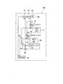
- FIG. 12 is a schematic diagram of an elevator system 1100 according to an eleventh embodiment of the present invention.
- the elevator system 1100 according to the present embodiment includes a building 1101 and a lifting cage 1111 that moves up and down in the building 1101.
- a base station radio 1103a and an antenna 1102a are arranged on the floor of the building 1101.
- a base station radio 1103b and an antenna 1102b are arranged on the ceiling surface of the building 1101.
- the elevator cage 1111 is equipped with antennas 1112a and 1112b, a terminal radio 1113, and a high-frequency cable 1114 connecting them.
- the base station radios 1103a and 1103b, the terminal radio 1113, and the antennas 1102a, 1102b, 1112a, and 1112b are configured similarly to the transceiver 400 (see FIGS. 10 and 11) in the tenth embodiment, for example.
- the terminal radio 1113 transmits and receives information signals to and from the base station radios 1103a and 1103b in both directions using both linearly polarized electromagnetic waves and rotationally polarized electromagnetic waves.
- the base station radios 1103a and 1103b and the terminal radio 1113 communicate with each other using the inside of the building 1101 as a radio transmission medium. Therefore, the electromagnetic wave is subjected to multiple reflections by the inner wall of the building 1101 and the outer wall of the elevating cage 1111 to form a multiple wave interference environment. Further, the propagation path of electromagnetic waves may be altered due to artificial interference from the outside.
- FIG. 13 is a schematic diagram of a substation monitoring system 1200 according to the twelfth embodiment of the present invention.
- the substation equipment monitoring system 1200 of the present embodiment includes a plurality of substation equipment 1201 and a plurality of base station devices 1211. However, the number of base station apparatuses 1211 is smaller than the number of substation facilities 1201.
- Each substation 1201 is provided with a terminal station radio 1203 and an antenna 1202.
- Each base station apparatus 1211 includes an antenna 1212 and a base station radio 1213.
- the base station radio 1213, the antenna 1212, the terminal station radio 1203, and the antenna 1202 are configured similarly to the transceiver 400 (see FIGS. 10 and 11) in the tenth embodiment, for example. Accordingly, each terminal station radio 1203 transmits and receives information signals to and from any base station radio 1213 using both linearly polarized electromagnetic waves and rotationally polarized electromagnetic waves.
- the dimensions of the substation equipment 1201 are on the order of several meters, which is overwhelmingly larger than wavelengths corresponding to several hundred MHz to several GHz, which are electromagnetic wave frequencies used by the base station radio 1213 and the terminal station radio 1203. Accordingly, the electromagnetic waves output from the terminal station radio 1203 and the base station radio 1213 are subjected to multiple reflections by the plurality of substation facilities 1201 to form a multiwave interference environment.
- the propagation path of electromagnetic waves may be altered due to artificial interference from outside.
- the present invention is not limited to the above-described embodiments, and various modifications can be made.
- the above-described embodiments are illustrated for easy understanding of the present invention, and are not necessarily limited to those having all the configurations described. Further, a part of the configuration of an embodiment can be replaced with the configuration of another embodiment, and the configuration of another embodiment can be added to the configuration of an embodiment. Further, it is possible to delete a part of the configuration of each embodiment, or to add or replace another configuration. Examples of possible modifications to the above embodiment are as follows.
- Each of the receivers, transmitters, and transceivers shown in the first to tenth embodiments may be realized by a DSP or may be configured by a discrete circuit. Further, it may be realized using an ASIC (Application Specific Integrated Circuit), an FPGA (field-programmable gate array), or the like.
- ASIC Application Specific Integrated Circuit
- FPGA field-programmable gate array
- the receivers, transmitters, and transceivers shown in the first to tenth embodiments are other than the elevator system 1100 shown in the eleventh embodiment and the substation equipment monitoring system 1200 shown in the twelfth embodiment.
- the present invention may be applied to various systems.
Abstract
Description
この発明は上述した事情に鑑みてなされたものであり、適切な通信が実現できる送信機および受信機を提供することを目的とする。
図1は、本発明の第1実施形態による無線通信システムのブロック図である。
本実施形態による無線通信システムは、送信機201と、受信機301とを有している。
送信機201は、空間的に直交する送信アンテナ1,2を有している。例えば、送信アンテナ1の偏波面が垂直(V)であるとすると、送信アンテナ2の偏波面は水平(H)になる。また、送信機201は、情報信号発生器4と、送信部2011(第1の送信部)と、送信部2012(第2の送信部)と、を有している。情報信号発生器4は、受信機301に伝送しようとする角周波数ωIの情報信号を出力する。送信部2011,2012は、該情報信号を変調して無線周波数帯の送信信号を生成し、生成した送信信号を送信アンテナ1,2に供給する。
受信機301は、送信機201から送信された電磁波を受信するために、空間的に直交する受信アンテナ61,62を有している。例えば、受信アンテナ61の偏波面が垂直(V)であるとすると、受信アンテナ62の偏波面は水平(H)になる。乗算器73(第1の受信部)は、受信アンテナ61の受信信号と、搬送周波数余弦発振器72から出力されたcosωctとを乗算する。乗算器74(第1の逆拡散部)は、直交符号生成回路71(第1の逆拡散部)から出力された直交符号#1と、乗算器73の出力信号とを乗算する。
送信機201から送信された電磁波は、受信機301に到達するまでに様々な電波散乱体で反射される。ここで、電波散乱体の表面がスネルの反射則を満足するのであれば、電磁波は、電波散乱体の表面で反射する際に、該電波散乱体の表面の法線ベクトルと電磁波の該表面への入射ベクトルに固有な偏波ベクトルのシフトを受ける。そして、偏波ベクトルのシフトを受けた複数の無線伝搬路を経由して、電磁波は受信機301に到達する。
図2は、本発明の第2実施形態による無線通信システムのブロック図である。なお、図2において図1の各部に対応する部分には同一の符号を付し、その説明を省略することがある。
本実施形態による無線通信システムは、送信機201と、受信機302とを有している。ここで、送信機201の構成は第1実施形態のもの(図1参照)と同様であるため、受信機302の構成について詳述する。
図3は、本発明の第3実施形態による無線通信システムのブロック図である。なお、図3において図1,図2の各部に対応する部分には同一の符号を付し、その説明を省略することがある。
本実施形態による無線通信システムは、送信機203と、受信機303とを有している。また、送信機203は、情報信号発生器4から供給された情報信号を送信アンテナ1,2に供給する、2つの送信部2031,2032を有している。
送信機203の送信部2031において、情報信号発生器4から出力された情報信号は、乗算器7にて直交符号#1で拡散される。搬送周波数正弦発振器31(第1の正弦発振器)は、sinω1tを出力し、搬送周波数正弦発振器32(第2の正弦発振器)は、sinω2tを出力する。ここで、角周波数ω1(搬送周波数、第1の周波数)および角周波数ω2(搬送周波数、第2の周波数)は、相互に近接した(例えば、ω1がω2の±10%以内の)搬送波の角周波数である。また、乗算器33は、乗算器7の出力信号とsinω1tとを乗算し、乗算器34は、乗算器7の出力信号とsinω2tとを乗算する。減算器35は、乗算器33の出力信号から乗算器34の出力信号を減算し、減算結果を送信アンテナ1に供給する。この結果、送信部2031によって送信アンテナ1から送信される電磁波は、二つの角周波数ω1,ω2の差の二分の一をビート角周波数とする正弦ビート波になる。
受信機303は、第2実施形態の受信機302(図2参照)と同様に、空間的に互いに直交する3つの受信アンテナ61,62,63と、これら受信アンテナ61,62,63からの3系統の受信信号に対して角度重み付けを行い、空間的に直交する二つのアンテナを仮想的に形成し、2系統の疑似受信信号に変換する偏波回転回路60と、を有している。
図4は、本発明の第4実施形態による無線通信システムのブロック図である。なお、図4において図1~図3の各部に対応する部分には同一の符号を付し、その説明を省略することがある。
本実施形態による無線通信システムは、送信機204と、受信機304とを有している。また、送信機204は、情報信号発生器4から供給された情報信号を送信アンテナ1,2に供給する、2つの送信部2011,2042を有している。
まず、送信部2011は、第1実施形態(図1参照)のものと同様である。すなわち、送信部2011は、情報信号を直交符号#1で拡散し、搬送波角周波数がωcであって回転角周波数ωpを有する回転偏波の電磁波を、送信アンテナ1,2を介して出力する。また、送信部2042において、情報信号発生器4から出力された情報信号は、乗算器8にて直交符号#2で拡散される。
また、受信機304の構成は、第2実施形態の受信機302(図2参照)と比較すると、搬送周波数余弦発振器82に代えて搬送周波数余弦発振器182が設けられ、搬送周波数余弦発振器86に代えて搬送周波数正弦発振器186が設けられている。搬送周波数余弦発振器182はcosωctを出力し、搬送周波数正弦発振器186はsinωctを出力する。上述した点を除けば、受信機304の構成は受信機302のものと同様である。
図5は、本発明の第5実施形態による無線通信システムのブロック図である。なお、図5において図1~図4の各部に対応する部分には同一の符号を付し、その説明を省略することがある。本実施形態による無線通信システムは、送信機205と、受信機(図示せず)とを有している。なお、受信機は、第1,第2実施形態における受信機301,302(図1,図2参照)のうち何れかを適用するとよい。
図6は、本発明の第6実施形態による無線通信システムのブロック図である。なお、図6において図1~図5の各部に対応する部分には同一の符号を付し、その説明を省略することがある。本実施形態による無線通信システムは、送信機203(図3参照)と、受信機306とを有している。なお、送信機203は、図6においては図示を省略する。
図7は、本発明の第7実施形態による無線通信システムのブロック図である。なお、図7において図1~図6の各部に対応する部分には同一の符号を付し、その説明を省略することがある。
本実施形態による無線通信システムは、送信機207と、受信機307とを有している。
送信機207は、情報信号発生器4と、BPSK変調回路28と、送信部2071,2072と、送信アンテナ1,2とを有している。送信機207において、情報信号発生器4から出力された情報信号は、BPSK変調回路28によって二値デジタル信号に変換される。送信部2071内の乗算器7は、直交符号#1と二値デジタル信号とを乗算し、乗算結果を出力する。この乗算結果は、乗算器13においてcosωptと乗算され、乗算器14においてsinωptと乗算される。なお、ωpは、第1実施形態のものと同様に、回転偏波の回転角周波数である。
受信機307は、第2実施形態の受信機302(図2参照)と同様に、空間的に互いに直交する3つの受信アンテナ61,62,63と、これら受信アンテナ61,62,63からの3系統の受信信号に対して角度重み付けを行い、空間的に直交する二つのアンテナを仮想的に形成し、2系統の疑似受信信号に変換する偏波回転回路60と、を有している。
図8は、本発明の第8実施形態による無線通信システムのブロック図である。なお、図8において図1~図7の各部に対応する部分には同一の符号を付し、その説明を省略することがある。
本実施形態による無線通信システムは、送信機208と、受信機308とを有している。
図9は、本発明の第9実施形態による無線通信システムのブロック図である。なお、図9において図1~図8の各部に対応する部分には同一の符号を付し、その説明を省略することがある。
本実施形態による無線通信システムは、送信機209と、受信機309とを有している。
図10、図11は、本発明の第10実施形態による無線通信システムのブロック図である。なお、図10,図11において図1~図9の各部に対応する部分には同一の符号を付し、その説明を省略することがある。
本実施形態による無線通信システムは、双方向通信を行う2台の送受信機を有している。但し、図10,図11には、そのうち一方の送受信機400のみを図示する。送受信機400と、図示せぬ相手側の送受信機とは同様に構成されているが、送信に用いられる拡散符号は異なっている。すなわち、送受信機400は、直交符号#1,#2を送信用の拡散符号として適用し、相手側の送受信機は、直交符号#3,#4を送信用の拡散符号として適用する。なお、直交符号#1~#4は、相互に直交する。
次に、図12は、本発明の第11実施形態による昇降機システム1100の模式図である。
本実施形態の昇降機システム1100は、建物1101と、建物1101内を昇降する昇降カゴ1111とを有している。建物1101の床面には、基地局無線機1103aと、アンテナ1102aとが配置されている。また、建物1101の天井面には、基地局無線機1103bと、アンテナ1102bとが配置されている。
図13は、本発明の第12実施形態による変電設備監視システム1200の模式図である。
本実施形態の変電設備監視システム1200は、複数の変電設備1201と、複数の基地局装置1211と、を有している。但し、変電設備1201の数よりも、基地局装置1211の数が少ない。
各変電設備1201には、端末局無線機1203と、アンテナ1202とが配置されている。また、各基地局装置1211は、アンテナ1212と、基地局無線機1213とを有している。
本発明は上述した実施形態に限定されるものではなく、種々の変形が可能である。上述した実施形態は本発明を理解しやすく説明するために例示したものであり、必ずしも説明した全ての構成を備えるものに限定されるものではない。また、ある実施形態の構成の一部を他の実施形態の構成に置き換えることが可能であり、また、ある実施形態の構成に他の実施形態の構成を加えることも可能である。また、各実施形態の構成の一部について削除し、若しくは他の構成の追加・置換をすることが可能である。上記実施形態に対して可能な変形は、例えば以下のようなものである。
4 情報信号発生器
5,6 直交符号生成回路
7 乗算器(第1の重畳回路)
8 乗算器(第2の重畳回路)
9 同期信号生成回路
11 偏波回転周波数余弦発振器(偏波面回転用発振器)
12 偏波回転周波数正弦発振器(偏波面回転用発振器)
19 搬送周波数余弦発振器(搬送用発振器)
27 信号切替回路
31 搬送周波数正弦発振器(第1の正弦発振器)
32 搬送周波数正弦発振器(第2の正弦発振器)
41 搬送周波数余弦発振器(第1の余弦発振器)
42 搬送周波数余弦発振器(第2の余弦発振器)
61,62,63 受信アンテナ
65 減算器(復元部)
71 直交符号生成回路(第1の逆拡散部)
73 乗算器(第1の受信部)
74 乗算器(第1の逆拡散部)
81 直交符号生成回路(第2の逆拡散部)
83,87 乗算器(第2の受信部)
84,88 乗算器(第2の逆拡散部)
201,203,204,205,207,208,209 送信機
301,302,303,304,306,307,308,309 受信機
385 直交符号生成回路(第3の逆拡散部)
388 乗算器(第3の逆拡散部)
2011,2031,2071,2081 送信部(第1の送信部)
2012,2032,2042,2072,2082,2092 送信部(第2の送信部)
ω1 角周波数(搬送周波数、第1の周波数)
ω2 角周波数(搬送周波数、第2の周波数)
ωc 搬送波角周波数(搬送周波数)
ωp 回転角周波数(回転周波数)
θz1,θz2,…,θzn 非検出角
ωI 角周波数
#1 直交符号(第1の直交符号)
#2 直交符号(第2の直交符号)
#3 直交符号(第3の直交符号)
V',H' 疑似受信信号
Claims (16)
- 情報信号を変調し偏波面が回転する第1の電波を発生させる第1の送信部と、
前記情報信号を変調し偏波面が固定である第2の電波を発生させる第2の送信部と、
を有することを特徴とする送信機。 - 前記第1の送信部は、拡散符号である第1の直交符号を前記第1の電波に重畳させる第1の重畳回路を有し、
前記第2の送信部は、前記第1の直交符号に対して互いに直交する第2の直交符号を前記第2の電波に重畳させる第2の重畳回路を有する
ことを特徴とする請求項1に記載の送信機。 - 前記第2の送信部は、前記第1の直交符号および前記第2の直交符号に対して互いに直交する第3の直交符号を前記第2の電波に重畳させる
ことを特徴とする請求項2に記載の送信機。 - 偏波面が空間的に直交する複数の送信アンテナをさらに有し、
前記第1の送信部は、複数の前記送信アンテナを介して前記第1の電波を発生させ、
前記第2の送信部は、複数の前記送信アンテナを介して前記第2の電波を発生させる
ことを特徴とする請求項1に記載の送信機。 - 前記第1の送信部および前記第2の送信部は、前記第1の電波と前記第2の電波とを同一時刻に発生させる
ことを特徴とする請求項4に記載の送信機。 - 前記第1の送信部は、複数の搬送周波数を用いて、前記搬送周波数によって定まる回転周波数で偏波面が回転する前記第1の電波を発生するものであり、
前記第2の送信部は、複数の前記搬送周波数を用いて、前記第2の電波を発生するものである
ことを特徴とする請求項5に記載の送信機。 - 前記第1の送信部は、
前記第1の電波の偏波面の回転周波数に対応する偏波面回転用発振器と、
前記第1の電波の搬送周波数に対応する搬送用発振器と、
を有し、前記第1の電波は、前記搬送周波数と前記回転周波数との和、および前記搬送周波数と前記回転周波数との差の成分を有する
ことを特徴とする請求項1に記載の送信機。 - 前記第1の送信部は、第1の周波数の正弦波を発生する第1の正弦発振器と、前記第1の周波数の余弦波を発生する第1の余弦発振器と、第2の周波数の正弦波を発生する第2の正弦発振器と、前記第2の周波数の余弦波を発生する第2の余弦発振器と、を有し、
前記第1の電波の偏波面は、前記第1および第2の周波数の差の半分の回転周波数で回転し、
前記第2の電波は、搬送周波数が前記第1の周波数である成分と、搬送周波数が前記第2の周波数である成分とを含む
ことを特徴とする請求項1に記載の送信機。 - 前記情報信号を出力する情報信号発生器と、
同期信号を生成する同期信号生成回路と、
前記情報信号または前記同期信号のうち一方を選択し、前記第1の送信部および前記第2の送信部に供給する信号切替回路と、
をさらに有することを特徴とする請求項1に記載の送信機。 - 情報信号を変調し偏波面が回転する第1の電波を復調する第1の受信部と、
前記情報信号を変調し偏波面が固定である第2の電波を復調する第2の受信部と、
を有し、前記第1および第2の受信部の受信結果に基づいて前記情報信号を復元する
ことを特徴とする受信機。 - 前記第1の電波は、拡散符号である第1の直交符号で前記情報信号を拡散された成分を含むものであり、前記第2の電波は、前記第1の直交符号に対して互いに直交する拡散符号である第2の直交符号で前記情報信号拡散された成分を含むものであり、
前記第1の受信部の復調結果を前記第1の直交符号で逆拡散する第1の逆拡散部と、
前記第2の受信部の復調結果を前記第2の直交符号で逆拡散する第2の逆拡散部と、
をさらに有することを特徴とする請求項10に記載の受信機。 - 前記第2の電波は、前記第1の直交符号および前記第2の直交符号に対して互いに直交する拡散符号である第3の直交符号で前記情報信号を拡散させた成分を含むものであり、
前記第2の受信部の復調結果を前記第3の直交符号で逆拡散する第3の逆拡散部
をさらに有することを特徴とする請求項11に記載の受信機。 - 偏波面が空間的に直交する複数の受信アンテナをさらに有し、
前記第1の受信部は、複数の前記受信アンテナのうち一方を介して前記第1の電波を受信するものであり、
前記第2の受信部は、複数の前記受信アンテナの双方を介して前記第2の電波を受信するものである
ことを特徴とする請求項10に記載の受信機。 - 前記第1の受信部および前記第2の受信部は、前記第1の電波と前記第2の電波とを同一時刻に受信する
ことを特徴とする請求項13に記載の受信機。 - 前記第1の逆拡散部の出力信号と、前記第2の逆拡散部の出力信号との差分に基づいて、前記情報信号を復元する復元部
をさらに有することを特徴とする請求項11に記載の受信機。 - 偏波面が空間的に直交する三以上の受信アンテナと、
三以上の前記受信アンテナの受信信号に重みづけを施し二系統の疑似受信信号を出力する偏波回転回路と、
をさらに有し、
前記第1の受信部は、二系統の前記疑似受信信号のうち一方を前記第1の電波として受信するものであり、
前記第2の受信部は、二系統の前記疑似受信信号の双方を前記第2の電波として受信するものである
ことを特徴とする請求項10に記載の受信機。
Priority Applications (4)
| Application Number | Priority Date | Filing Date | Title |
|---|---|---|---|
| US15/761,225 US10630370B2 (en) | 2016-05-10 | 2017-05-09 | Transmitter and receiver |
| SG11201802305QA SG11201802305QA (en) | 2016-05-10 | 2017-05-09 | Transmitter and receiver |
| CN201780003185.3A CN108028695B (zh) | 2016-05-10 | 2017-05-09 | 发送机以及接收机 |
| JP2018517024A JP6439079B2 (ja) | 2016-05-10 | 2017-05-09 | 送信機および受信機 |
Applications Claiming Priority (2)
| Application Number | Priority Date | Filing Date | Title |
|---|---|---|---|
| JP2016094205 | 2016-05-10 | ||
| JP2016-094205 | 2016-05-10 |
Publications (1)
| Publication Number | Publication Date |
|---|---|
| WO2017195761A1 true WO2017195761A1 (ja) | 2017-11-16 |
Family
ID=60267408
Family Applications (1)
| Application Number | Title | Priority Date | Filing Date |
|---|---|---|---|
| PCT/JP2017/017487 WO2017195761A1 (ja) | 2016-05-10 | 2017-05-09 | 送信機および受信機 |
Country Status (5)
| Country | Link |
|---|---|
| US (1) | US10630370B2 (ja) |
| JP (1) | JP6439079B2 (ja) |
| CN (1) | CN108028695B (ja) |
| SG (1) | SG11201802305QA (ja) |
| WO (1) | WO2017195761A1 (ja) |
Cited By (1)
| Publication number | Priority date | Publication date | Assignee | Title |
|---|---|---|---|---|
| US10218426B1 (en) | 2017-09-11 | 2019-02-26 | Kabushiki Kaisha Toshiba | Antenna device, wireless communication device and signal transmission method |
Families Citing this family (1)
| Publication number | Priority date | Publication date | Assignee | Title |
|---|---|---|---|---|
| JP7139188B2 (ja) * | 2018-08-21 | 2022-09-20 | 株式会社日立製作所 | 送信機 |
Citations (3)
| Publication number | Priority date | Publication date | Assignee | Title |
|---|---|---|---|---|
| JPH0865225A (ja) * | 1994-08-25 | 1996-03-08 | Matsushita Electric Works Ltd | 偏波ダイバーシティアンテナ装置 |
| JP2006340234A (ja) * | 2005-06-03 | 2006-12-14 | Sony Corp | アンテナ装置、無線通信装置、その制御方法、コンピュータ処理可能なプログラム及びその記録媒体 |
| JP2008527950A (ja) * | 2004-11-30 | 2008-07-24 | ザ リージェンツ オブ ザ ユニバーシティ オブ カリフォルニア | 適応多入出力(mimo)無線通信システムのための方法と装置 |
Family Cites Families (12)
| Publication number | Priority date | Publication date | Assignee | Title |
|---|---|---|---|---|
| US5038150A (en) | 1990-05-14 | 1991-08-06 | Hughes Aircraft Company | Feed network for a dual circular and dual linear polarization antenna |
| WO2003061170A1 (fr) * | 2002-01-10 | 2003-07-24 | Fujitsu Limited | Procede de multiplexage de pilote dans un systeme ofdm et procede de reception ofdm |
| CN1241336C (zh) | 2002-03-20 | 2006-02-08 | 启碁科技股份有限公司 | 线性极化讯号与圆形极化讯号接收方法与装置 |
| CN100574164C (zh) * | 2003-02-05 | 2009-12-23 | 日本电信电话株式会社 | 无线电通信系统、发送机、接收机及通信、发送和接收方法 |
| US7952525B2 (en) | 2005-06-03 | 2011-05-31 | Sony Corporation | Antenna device associated wireless communication apparatus and associated control methodology for multi-input and multi-output communication systems |
| GB0602530D0 (en) * | 2006-02-09 | 2006-03-22 | Quintel Technology Ltd | Phased array antenna system with multiple beams |
| US7957425B2 (en) | 2009-07-07 | 2011-06-07 | Nigel Iain Stuart Macrae | Communicating distinct data using polarized data signals |
| JP5564363B2 (ja) | 2010-08-25 | 2014-07-30 | 日本放送協会 | 偏波mimo−ofdm伝送方式の送信装置及び受信装置 |
| KR101878211B1 (ko) * | 2011-09-19 | 2018-07-16 | 삼성전자주식회사 | 무선 통신 시스템에서 다중 빔포밍 송수신기를 운용하기 위한 장치 및 방법 |
| US8918129B2 (en) | 2011-09-20 | 2014-12-23 | Nigel Macrae | Increasing capacity in communications systems using polarized data signals |
| CN103873122B (zh) | 2012-12-11 | 2019-02-19 | 中兴通讯股份有限公司 | 天线信号的发送方法、装置及设备 |
| JP5986323B2 (ja) * | 2013-10-18 | 2016-09-06 | 株式会社日立製作所 | 高セキュア無線通信システム |
-
2017
- 2017-05-09 JP JP2018517024A patent/JP6439079B2/ja not_active Expired - Fee Related
- 2017-05-09 CN CN201780003185.3A patent/CN108028695B/zh active Active
- 2017-05-09 WO PCT/JP2017/017487 patent/WO2017195761A1/ja active Application Filing
- 2017-05-09 SG SG11201802305QA patent/SG11201802305QA/en unknown
- 2017-05-09 US US15/761,225 patent/US10630370B2/en active Active
Patent Citations (3)
| Publication number | Priority date | Publication date | Assignee | Title |
|---|---|---|---|---|
| JPH0865225A (ja) * | 1994-08-25 | 1996-03-08 | Matsushita Electric Works Ltd | 偏波ダイバーシティアンテナ装置 |
| JP2008527950A (ja) * | 2004-11-30 | 2008-07-24 | ザ リージェンツ オブ ザ ユニバーシティ オブ カリフォルニア | 適応多入出力(mimo)無線通信システムのための方法と装置 |
| JP2006340234A (ja) * | 2005-06-03 | 2006-12-14 | Sony Corp | アンテナ装置、無線通信装置、その制御方法、コンピュータ処理可能なプログラム及びその記録媒体 |
Cited By (1)
| Publication number | Priority date | Publication date | Assignee | Title |
|---|---|---|---|---|
| US10218426B1 (en) | 2017-09-11 | 2019-02-26 | Kabushiki Kaisha Toshiba | Antenna device, wireless communication device and signal transmission method |
Also Published As
| Publication number | Publication date |
|---|---|
| JP6439079B2 (ja) | 2018-12-19 |
| JPWO2017195761A1 (ja) | 2018-08-02 |
| CN108028695B (zh) | 2021-01-15 |
| CN108028695A (zh) | 2018-05-11 |
| SG11201802305QA (en) | 2018-04-27 |
| US20180262260A1 (en) | 2018-09-13 |
| US10630370B2 (en) | 2020-04-21 |
Similar Documents
| Publication | Publication Date | Title |
|---|---|---|
| JP5914746B2 (ja) | 無線通信システム、送信機、受信機、昇降機制御システム、及び、変電設備監視システム | |
| JP6228108B2 (ja) | 無線通信システム | |
| JP6280993B2 (ja) | 無線通信システムおよびその利用システム | |
| JP6439079B2 (ja) | 送信機および受信機 | |
| CN108123722B (zh) | 无线系统、屏蔽区域内无线系统、无线设备 | |
| JP6581437B2 (ja) | 無線通信システム | |
| CN108123731B (zh) | 无线系统、升降机控制系统、变电设备监视系统 | |
| JP6475042B2 (ja) | 無線送信機、無線受信機、および無線通信システム | |
| JP6420934B2 (ja) | 無線システム、およびそれを用いた昇降機制御システム、変電設備監視システム | |
| WO2017213102A1 (ja) | 無線システム、およびそれを用いた昇降機制御システム、変電設備監視システム | |
| JP6483548B2 (ja) | 無線通信システム、および、それを用いた昇降機システム、変電設備監視システム | |
| WO2018096674A1 (ja) | 無線システム、およびそれを用いた昇降機制御システム、変電設備監視システム | |
| WO2018185883A1 (ja) | 無線通信システム | |
| EP3644527B1 (en) | Radio communication system and radio communication method | |
| US10148338B1 (en) | Wireless communication system | |
| JP2019102994A (ja) | 無線通信システムおよび無線監視制御システム | |
| JP2020072293A (ja) | 無線システム及び無線通信方法 | |
| JP2018160887A (ja) | 送信装置および受信装置 |
Legal Events
| Date | Code | Title | Description |
|---|---|---|---|
| ENP | Entry into the national phase |
Ref document number: 2018517024 Country of ref document: JP Kind code of ref document: A |
|
| WWE | Wipo information: entry into national phase |
Ref document number: 15761225 Country of ref document: US |
|
| WWE | Wipo information: entry into national phase |
Ref document number: 11201802305Q Country of ref document: SG |
|
| NENP | Non-entry into the national phase |
Ref country code: DE |
|
| 121 | Ep: the epo has been informed by wipo that ep was designated in this application |
Ref document number: 17796122 Country of ref document: EP Kind code of ref document: A1 |
|
| 122 | Ep: pct application non-entry in european phase |
Ref document number: 17796122 Country of ref document: EP Kind code of ref document: A1 |