WO2017195644A1 - 連続気泡除去方法および連続気泡除去装置 - Google Patents
連続気泡除去方法および連続気泡除去装置 Download PDFInfo
- Publication number
- WO2017195644A1 WO2017195644A1 PCT/JP2017/016835 JP2017016835W WO2017195644A1 WO 2017195644 A1 WO2017195644 A1 WO 2017195644A1 JP 2017016835 W JP2017016835 W JP 2017016835W WO 2017195644 A1 WO2017195644 A1 WO 2017195644A1
- Authority
- WO
- WIPO (PCT)
- Prior art keywords
- basic
- liquid
- container
- cam
- separate
- Prior art date
- Legal status (The legal status is an assumption and is not a legal conclusion. Google has not performed a legal analysis and makes no representation as to the accuracy of the status listed.)
- Ceased
Links
Images








Classifications
-
- B—PERFORMING OPERATIONS; TRANSPORTING
- B01—PHYSICAL OR CHEMICAL PROCESSES OR APPARATUS IN GENERAL
- B01D—SEPARATION
- B01D19/00—Degasification of liquids
- B01D19/0073—Degasification of liquids by a method not covered by groups B01D19/0005 - B01D19/0042
-
- B—PERFORMING OPERATIONS; TRANSPORTING
- B01—PHYSICAL OR CHEMICAL PROCESSES OR APPARATUS IN GENERAL
- B01D—SEPARATION
- B01D19/00—Degasification of liquids
- B01D19/0036—Flash degasification
-
- B—PERFORMING OPERATIONS; TRANSPORTING
- B01—PHYSICAL OR CHEMICAL PROCESSES OR APPARATUS IN GENERAL
- B01D—SEPARATION
- B01D19/00—Degasification of liquids
-
- B—PERFORMING OPERATIONS; TRANSPORTING
- B01—PHYSICAL OR CHEMICAL PROCESSES OR APPARATUS IN GENERAL
- B01D—SEPARATION
- B01D19/00—Degasification of liquids
- B01D19/0042—Degasification of liquids modifying the liquid flow
-
- B—PERFORMING OPERATIONS; TRANSPORTING
- B01—PHYSICAL OR CHEMICAL PROCESSES OR APPARATUS IN GENERAL
- B01D—SEPARATION
- B01D19/00—Degasification of liquids
- B01D19/0063—Regulation, control including valves and floats
-
- C—CHEMISTRY; METALLURGY
- C02—TREATMENT OF WATER, WASTE WATER, SEWAGE, OR SLUDGE
- C02F—TREATMENT OF WATER, WASTE WATER, SEWAGE, OR SLUDGE
- C02F1/00—Treatment of water, waste water, or sewage
- C02F1/20—Treatment of water, waste water, or sewage by degassing, i.e. liberation of dissolved gases
Definitions
- the present invention relates to an open cell removing method for removing bubbles contained in a liquid and an open cell removing apparatus for removing bubbles contained in a liquid.
- the present invention has been made in view of the above points, and an object of the present invention is to improve the bubble removal speed while suppressing an increase in the size of a device for removing bubbles.
- an open-cell removal method includes a main container (3), a basic pressurized container (17, 27, 37) connected to the main container and containing a basic working liquid, and a basic pressurized container.
- the liquid to be defoamed is repeatedly pressurized and depressurized, thereby repeatedly reducing and increasing the volume of the bubbles. Includes an order, the. And the opening area of the said basic support part is larger than the opening area of the said basic connection part.
- the continuous bubble removing device for achieving the above object includes a main container (3) through which bubbles are removed and a basic pressurized container that is connected to the main container and contains a basic working liquid. (17, 27, 37) and a basic movable part (C, 39a) attached to the basic pressurization container so as to be displaceable, wherein the basic pressurization container has the basic movable part.
- Basic working fluid A force is applied again, and the basic working liquid receives the force repeatedly as the basic movable portion reciprocates, so that the defoaming target liquid is removed from the region surrounded by the basic connecting portion.
- the volume of the bubbles contained in the defoaming target liquid is repeatedly reduced and
- the opening area of the basic support part is larger than the opening area of the basic connection part.
- the opening area of the basic support part that supports the basic movable part is larger than the opening area of the basic connection part that is a path through which the force according to the reciprocating displacement of the basic movable part is transmitted to the liquid to be defoamed. . Therefore, it is possible to increase the pressure applied to the defoaming target liquid from the basic connection part as compared with the case where there is no basic pressurizing container, while suppressing the amplitude of displacement of the movable part. As a result, the bubble removal speed can be improved while suppressing an increase in the size of the device for removing bubbles.
- the continuous bubble removing device rotates the basic movable portion (C, 39a) by rotating the basic container (3) through which the defoaming target liquid containing bubbles flows and the basic movable portion (C, 39a).
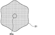
- FIG. 4 is a IV arrow view of the cam in FIG. 1.
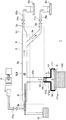
- the continuous bubble removing device 1 of the present embodiment includes a main container 3, a high-pressure microfeeder 5, electronic balances 9 a and 9 b, variable throttle valves 11 a, 11 b and 11 c, a pressurized container 17, and a drive mechanism 19. Composed of etc.
- the main container 3 is formed with one liquid inlet 3b and two outlets 3c, 3d.
- the outlet 3c is an outlet through which bubbles and liquid to be defoamed flow out.
- the outlet 3c is referred to as a bubble outlet.
- the outlet 3d is an outlet through which the defoaming target liquid after the bubbles are removed flows out.
- the outlet 3d is referred to as a liquid outlet.
- the main container 3 has a main channel 3a for sending the liquid to be defoamed from the liquid inlet 3b to the bubble outlet 3c and the liquid outlet 3d, and is branched from the main channel 3a while communicating with the main channel 3a. And a branch channel 13a extending in the direction.
- the main flow path 3a and the branch flow path 13a contain the defoaming target liquid containing bubbles when the continuous bubble removing apparatus 1 is operated, and are filled with the defoaming target liquid.
- a sight glass 6 is attached to the main flow path 3a, and the locus of bubbles in the main flow path 3a can be visually confirmed through the sight glass 6.
- An electrode 8 for generating bubbles is inserted from the liquid inlet 3b into the main flow path 3a.
- the electrode 8 is connected to the constant voltage generator 10.
- the sight glass 6, the electrode 8, and the constant voltage generator 10 are used for verifying the bubble separation effect, and are not essential for the continuous bubble removing device 1. In normal use of the continuous bubble removing device 1, bubbles are already contained in the defoaming target liquid that enters the main flow path 3a from the liquid inlet.
- the liquid inlet 3b is provided at one end of the main flow path 3a.
- the liquid inlet 3b is connected to the high-pressure microfeeder 5 via the variable throttle valve 11a.
- the high-pressure microfeeder 5 corresponds to a pressure feeding unit.
- the bubble outlet 3c is provided at the other end of the main flow path 3a.
- the bubble outlet 3c is connected to the recovery pipe 15a via the variable throttle valve 11b.
- the recovery pipe 15a is a pipe for guiding the fluid flowing out from the variable throttle valve 11b to a weighing beaker placed on the electronic balance 9a.
- the main flow path 3a is branched into a lower passage 3e and an upper passage 3f downstream from the liquid inlet 3b and upstream from the bubble outlet 3c and liquid outlet 3d.
- the lower passage 3e is branched downward from the upper passage 3f.
- the downstream end of the lower passage 3e is a liquid outlet 3d, and the downstream end of the upper passage 3f is a bubble outlet 3c.
- the liquid outlet 3d is connected to the recovery pipe 15b via the variable throttle valve 11c.
- the recovery pipe 15b is a pipe for guiding the fluid flowing out from the variable throttle valve 11c to a weighing beaker placed on the electronic balance 9b.
- the branch channel 13a is branched downward from the upstream side of the branch point of the lower channel 3e and the upper channel 3f of the main channel 3a.
- the direction in which the branch channel 13a branches from the main channel 3a extends downward is to reduce the possibility of bubbles entering the liquid to be defoamed that is filled in the branch channel 13a.
- An elastic film 14 made of an elastic body is attached to the lower end of the branch channel 13a.
- the outer edge portion of the elastic membrane 14 is fixed to the lower end of the branch channel 13a, and the upper side surface of the elastic membrane 14 is in contact with the liquid to be defoamed. Portions other than the outer edge portion of the elastic membrane 14 can be displaced with respect to the branch channel 13a. Since this elastic membrane 14 liquid-tightly seals the lower end of the branch flow path 13a, the defoaming target liquid in the main container 3 does not leak from the lower end of the branch flow path 13a.
- a pressurized container 17 is connected to the lower end of the branch channel 13a.
- the pressurization container 17 has a large diameter portion 171 and a small diameter portion 172.
- the large-diameter portion 171 and the small-diameter portion 172 are connected to each other, and the small-diameter portion 172 is closer to the branch channel 13a than the large-diameter portion 171.
- the opening area of the large diameter portion 171 is sufficiently larger than the opening area of the small diameter portion 172.
- connection between the pressurized container 17 and the lower end of the branch channel 13a is realized by connecting the open end 172a on the upper side of the small diameter portion 172 (that is, the branch channel 13a side) with the lower end of the branch channel 13a.
- the open end 172a is closed by a piston E made of resin or the like.
- the piston E is supported by the inner wall of the open end 172a.
- the piston E liquid-tightly seals the opening end 172a, but is slidable with respect to the inner wall of the opening end 172a. Accordingly, the piston E can be reciprocally displaced along the axial direction X2 of the small diameter portion 172 while being supported by the inner wall of the opening end portion 172a.
- the piston E and the elastic film 14 are reciprocally displaced in the axial direction X2 while the upper end surface of the piston E and the lower end surface of the elastic film 14 are in contact with each other. Further, the area of the upper end surface of the piston E and the area of the lower end surface of the elastic film 14 are substantially the same.
- the branch channel 13a and the small diameter portion 172 are not in communication with each other, and the elastic membrane 14 and the piston E partition the branch channel 13a and the pressurized container 17 from each other.
- the working liquid 18 in the pressurized container 17 can urge the defoaming target liquid in the branch flow path 13a via the piston E and the elastic membrane 14.
- the piston E and the elastic membrane 14 correspond to a partition.
- the piston C is fitted in the inner wall of the open end 171a on the lower end side of the large diameter portion 171.
- the piston C closes the opening end 171a in a liquid-tight manner, but can be moved forward and backward along the axial direction X1 (that is, the vertical direction) of the large-diameter portion 171 while being supported by the inner wall of the opening end 171a. is there.
- the opening area of the opening end portion 171a on the lower end side of the large diameter portion 171 is sufficiently larger than the opening area of the opening end portion 172a on the upper end side of the small diameter portion 172.
- the working liquid 18 may be a liquid having a low viscosity, a high vapor pressure, and a high boiling point.
- the working liquid 18 may be a cutting oil of a machine tool, a salad oil, a silicon oil, or water.
- a drive mechanism 19 for displacing the piston C up and down is disposed below the piston C.
- the upward displacement of the piston C corresponds to a forward displacement, and the downward displacement corresponds to a backward displacement.
- the pressurization container 17 and the drive mechanism 19 constitute an excitation amount converter.
- the drive mechanism 19 includes a motor 20 serving as a drive source, a cam 21 attached to an output shaft 20a of the motor 20, a vibrator 22 driven up and down by the cam 21, and the like.
- the detailed structure related to the vibrator 22 is as shown in FIG.
- the vibrator 22 has a lower base portion 22a and a pressing rod 22b.
- the pressing bar 22b is a bar-shaped member extending in the vertical direction, and protrudes through the hole provided in the upper surface 23a of the support frame 23.
- the upper end portion of the pressing rod 22b is disposed so as to be in contact with the piston C.
- the upper end portion of the pressing rod 22b may be always connected to the piston C.
- the upper end of the pressing rod 22b may come into contact with the piston C when the vibrator 22 is displaced upward, and may be separated from the piston C when the vibrator 22 is displaced downward.
- the lower end of the pressing bar 22b is fixed to the lower base 22a.
- the lower base portion 22 a is slidably connected to a guide 24 that extends downward from the upper surface of the support frame 23.
- the vibrator 22 can be reciprocated up and down while being guided by the guide 24, and its up and down trajectory is along the extending direction of the guide 24.
- a compression coil spring 25 is interposed between the lower base portion 22a of the vibrator 22 and the upper surface 23a.
- the compression coil spring 25 surrounds the pressing rod 22b between the lower base portion 22a and the upper surface 23a. For this reason, the vibrator 22 is urged in the downward direction by the compression coil spring 25.
- a cam follower 26 is attached to the lower side of the lower base portion 22a of the vibrator 22 so as to be rotatable with respect to the lower base portion 22a. More specifically, the cam follower 26 has a roller and a rotating shaft. The rotation shaft is attached to the lower base portion 22a so as to be able to rotate and slide. The extending direction of the rotating shaft is orthogonal to the vertical direction and is parallel to the output shaft 20a.
- a disk-shaped roller is fixed perpendicularly to the rotating shaft.
- the rotating shaft and the roller rotate integrally.
- the outer periphery of the roller is in contact with the outer peripheral surface of the cam 21 (that is, the cam surface). This contact is maintained by the urging force of the compression coil spring 25.
- the vibrator 22 Since the cam 21 is rotationally driven by the motor 20 and the cam follower 26 is pushed up by the crest of the cam 21, the vibrator 22 is displaced upward, and the cam follower 26 is driven by the biasing force of the compression coil spring 25. If the valley is followed, the vibrator 22 is displaced downward. At this time, the entire cam follower 26 is dragged and rotated by the rotation of the cam, so that the strength of the force by which the vibrator 22 is urged in the direction other than the vertical direction by the cam 21 can be reduced.
- the upper end portion of the pressing bar 22b pushes the piston C and raises it.
- the upper end portion of the pressing rod 22b pulls the piston C back down when the vibrator 22 is displaced downward.
- the pressing rod 22b is not connected to the piston C, when the vibrator 22 is displaced downward, the upper end of the pressing rod 22b is separated from the piston C, and the piston C is displaced downward by the pressure received from the working liquid 18 and its own weight. .
- the piston C follows the pressing rod 22b with higher responsiveness when the pressing rod 22b is raised or lowered than when the pressing rod 22b is not connected. Therefore, when the pressing rod 22b is always connected to the piston C, the behavior of the piston C can be controlled in more detail than when the pressing rod 22b is not connected. For example, it is easy to control the rotation of the cam 21 to change the displacement amount of the piston C with the sine curve, but with the triangular wave.
- the sample liquid (highly viscous fluid) used in this example is a 0.800 wt% sodium polyacrylate aqueous solution.
- the viscosity curve of this sample liquid is as shown in FIG.
- this sample liquid (0.800 wt% sodium polyacrylate aqueous solution) exhibits a viscosity of 253 Pa ⁇ s and an increase in shear rate when the shear rate is very small. Accordingly, it has the property of reducing the viscosity (Shear viscosity). Therefore, this sample liquid is a liquid whose viscosity decreases when shearing occurs.
- the sample liquid is pumped from the liquid inlet 3b of the main container 3 into the main flow path 3a by the high-pressure microfeeder 5.
- the pumping pressure of the high-pressure microfeeder 5 is about 0.4 to 5 atmospheres.
- the sample liquid sent into the main channel 3a from the liquid inlet 3b of the main container 3 is directed toward the bubble outlet 3c and the liquid outlet 3d while filling the inside of the main channel 3a (including the branch channel 13a and the lower channel 3e). Flowing.
- variable throttle valves 11a, 11b, and 11c are throttled small. This is to increase the flow path resistance of the variable throttle valves 11a, 11b, and 11c to function as a resistance portion.
- the flow rate ratio between the bubble outlet 3c side and the liquid outlet 3d side can be set by adjusting the valve openings of the variable throttle valves 11b and 11c.
- variable throttle valves 11a, 11b, and 11c since the valve openings of the variable throttle valves 11a, 11b, and 11c are throttled very small, the flow resistance of the variable throttle valves 11a, 11b, and 11c becomes very large. Thereby, the sample liquid inside the main flow path 3a can be depressurized and pressurized.
- the high-pressure microfeeder 5 pumps liquid against the flow path resistance of the variable throttle valves 11a, 11b, and 11c.
- the constant voltage generator 10 is energized for a predetermined time, and bubbles are generated from the electrode 8. As a result, the sample liquid becomes a defoaming target liquid containing bubbles. And the drive mechanism 19 is operated continuously.
- the motor 20 rotates the cam 21 continuously.
- the vibrator 22 biased by the cam 21 via the cam follower 26 performs repetitive up / down displacement (that is, reciprocal displacement).
- the piston C is repeatedly displaced up and down by the repeated displacement of the vibrator 22.
- the piston C is supported by the opening end portion 171a and is displaced up and down with respect to the pressurized container 17, thereby repeatedly applying a force to the working liquid 18 accommodated in the pressurized container 17. Then, the working liquid 18 repeatedly receives a force along with the reciprocating displacement of the piston C, thereby moving the piston E up and down relative to the pressurized container 17 in a region surrounded by the open end 172a.
- the up-and-down displacement of the piston C is a displacement that pushes the working liquid 18 from the opening end 172a of the small diameter portion 172 toward the branch flow path 13a and pulls it back, that is, the working liquid in the small diameter portion 172. Acts as 18 reciprocating reciprocating displacements.
- the piston E and the elastic membrane 14 are repeatedly reciprocated at the opening end 172a of the small diameter portion 172 and the lower end of the branch channel 13a.
- the repeated up-and-down displacement of the vibrator 22, the repeated up-and-down displacement of the pistons C and E, and the repeated reciprocating displacement of the working liquid 18 all correspond to vibration.
- the reciprocating displacement of the piston E and the elastic membrane 14 acts on the sample liquid and bubbles (particularly, bubbles in and near the branch channel 13a) in the main container 3 from the region surrounded by the open end 172a, and the sample It repeatedly reduces and increases the pressure acting on liquids and bubbles.
- the variable throttle valves 11a, 11b, and 11c function as a resistance portion, and provide resistance to the flow of the liquid between the inside and the outside of the main flow path 3a. Therefore, the pressure change due to the reciprocating displacement of the piston E and the elastic membrane 14 works efficiently on the bubbles.
- the volume of the bubbles can be decreased and increased repeatedly.
- shearing occurs in the sample liquid around the bubble.
- the viscosity of the sample liquid around the bubbles decreases, and the bubbles rise at high speed in the liquid due to buoyancy.
- the bubbles rising in the sample liquid move along the upper end of the main flow path 3a along with the flow of the liquid in the main flow path 3a, and flow out together with the sample liquid from the bubble outlet 3c to the recovery pipe 15a via the variable throttle valve 11b. .
- Bubbles can be removed continuously.
- the opening area of the opening end portion 171a of the large diameter portion 171 greatly exceeds the opening area of the opening end portion 172a of the small diameter portion 172.
- the cross-sectional area perpendicular to the direction X1 of the piston C greatly exceeds the cross-sectional area perpendicular to the direction X2 of the piston E and the area of the lower surface of the elastic film 14.
- the displacement amount of the working liquid 18 at the opening end portion 172a of the small diameter portion 172 is larger than the displacement amount of the working liquid 18 on the opening end portion 171a side of the large diameter portion 171 when the piston C is reciprocally displaced.
- the amplitudes of the piston E and the elastic film 14 are larger than the amplitude of the piston C.
- the amount of change in the pressure of the sample liquid and the bubbles in the main container 3 increases, and the amount of increase / decrease in the volume of the bubbles also increases. Therefore, the efficiency of removing the bubbles by moving up is improved.
- the pressurized container 17 amplifies the amplitude of the piston C and transmits it to the piston E and the elastic film 14 to increase the amplitude thereof, the pressure of the vibration generated by the cam 21 is not changed.
- the amplitudes of the piston E and the elastic film 14 can be further increased.
- Sc is the cross-sectional area of the piston C
- ⁇ Vc is the volume change of the pressurized container 17 due to the displacement of the piston C
- ⁇ hc is the displacement amount of the piston C
- Se is the cross-sectional area of the piston E
- the main is the displacement due to the displacement of the piston E.
- the volume change of the container 3 is ⁇ Ve
- the configuration of the drive mechanism 19 for driving the piston C is as described above, and details of the operation will be described below.
- the shape of the cam 21 for applying vibration to the vibrator 22 is as shown in FIG.
- the height of the mountain is set to 30 times the actual height in order to make the shape easy to understand.
- the height of a mountain is 0.1 mm (amplitude is 0.05 mm)
- the number of mountains is 6, and the shape of the mountain is a modified sine curve.
- the displacement amount ⁇ he of the piston E is about 1 mm (as amplitude) by the amplification action. About 0.5 mm).
- 200 Hz is used as the frequency for applying vibration, but it may be a low frequency of 4000 Hz or less.
- 150 Hz may be used. That is, the vibration frequency, the pressure fluctuation range, and the phase are set so that the fluid viscosity in the vicinity of the bubble is lowered by shearing.
- a device of International Publication No. 2013/021849 using a speaker-type vibration generator is used as a vibration source.
- the ability of this vibration generator is 200 Hz even when there is no load, and the maximum amplitude is 0.4 mm, which is even smaller than this when loaded.
- the experimental conditions of the cam system of this example and the speaker system of the comparative example are as shown in Table 1 below.
- the flow rate ratio is the ratio of the outflow amount from the liquid outlet 3d to the total flow rate.
- Vmax is the maximum volume of bubbles
- Vmin is the minimum volume of bubbles
- r 0 A and ⁇ are constants
- S is a deformation rate tensor.
- t is the bubble diameter at time t
- t + ⁇ t is the bubble diameter at time t + ⁇ t.
- ⁇ t is a half-cycle time of bubble diameter vibration.
- the cam method In the shrinkage rate focusing only on the change in the bubble diameter due to expansion / contraction, the cam method showed a 1.8-fold change in bubble diameter as compared with the speaker method, and the shear rate was larger. Therefore, it can be said that the cam method can transmit stronger pressure vibration to the bubbles and the defoaming effect is improved as compared with the speaker method.
- the area of the piston C is larger than the area of the piston E, strong pressure vibration can be applied to the sample liquid and the bubbles while suppressing the amplitude of the vibrator 22. Therefore, the bubble removal speed can be improved while suppressing the drive mechanism 19 for removing the bubbles from becoming large.
- the piston C is reciprocated while being supported by the opening end 171a of the large-diameter portion 171, thereby defoaming from the region surrounded by the opening end 172a of the small-diameter portion 172 via the working liquid 18.
- the target liquid is repeatedly pressurized and depressurized. Thereby, the volume of bubbles can be reduced and increased repeatedly.
- the opening area of the opening end 171a of the large diameter portion 171 is larger than the opening area of the opening end 172a of the small diameter portion 172.
- the opening area of the opening end 171a that supports the piston C is larger than the opening area of the opening end 172a that is a path through which pressurization and decompression according to the reciprocation of the piston C is transmitted to the liquid to be defoamed. Is bigger. Therefore, the amplitude of the pressure applied to the liquid to be defoamed from the open end 172a can be increased as compared with the case where the pressurized container 17 is not provided, while suppressing the amplitude of the displacement of the piston C. As a result, it is possible to improve the bubble removal speed while suppressing an increase in the size of the drive mechanism for removing bubbles.
- the elastic film 14 is attached to the end of the main container 3 on the pressurized container 17 side to seal the liquid to be defoamed. Then, the piston E is attached to the open end 172 a of the pressurizing container 17 and seals the working liquid 18.
- the pressurized container 17 corresponds to a basic pressurized container
- the piston C corresponds to a basic movable part.
- the lower open end 171a of the large diameter portion 171 corresponds to a basic support portion
- the upper open end portion 172a of the small diameter portion 172 corresponds to a basic connection portion.
- the working liquid 18 corresponds to a basic working liquid.
- the cam 21 corresponds to a basic cam.
- the elastic film 14 corresponds to the main container side sealing body
- the piston E corresponds to the connection portion side sealing body.
- the main vessel 3 is provided with a main channel 3a, a liquid inlet 3b, a bubble outlet 3c, a liquid outlet 3d, and a branch channel 13a, which is the same as in the first embodiment.
- a second branch channel 13 b is further provided in the main container 3.
- the branch channel 13b is branched from the main channel 3a toward the lower side of the main channel 3a on the downstream side of the branch point between the main channel 3a and the branch channel 13a and on the upstream side of the outlets 3c and 3d. Is growing.
- An elastic film 141 made of an elastic body is attached to the lower end of the branch channel 13a (that is, the end portion on the pressurized container 27 side).
- the outer edge portion of the elastic membrane 141 is fixed to the lower end of the branch channel 13a, and the upper side surface of the elastic membrane 141 is in contact with the defoaming target liquid. Portions other than the outer edge portion of the elastic membrane 141 can be displaced with respect to the branch channel 13a. Since this elastic membrane 141 liquid-tightly seals the lower end of the branch channel 13a, the defoaming target liquid in the main container 3 does not leak from the lower end of the branch channel 13a.
- An elastic film 142 made of an elastic body is attached to the lower end of the branch channel 13b (that is, the end on the pressurized container 27 side).
- the outer edge portion of the elastic membrane 142 is fixed to the lower end of the branch channel 13b, and the upper side surface of the elastic membrane 142 is in contact with the liquid to be defoamed. Portions other than the outer edge portion of the elastic membrane 142 can be displaced with respect to the branch channel 13b. Since the elastic membrane 142 liquid-tightly seals the lower end of the branch channel 13b, the defoaming target liquid in the main container 3 does not leak from the lower end of the branch channel 13b.
- a pressurized container 27 is connected to the lower ends of the branch channels 13a and 13b.
- the pressurizing container 27 has one large-diameter portion 291, two small-diameter portions 292 and 293, and one relay portion 294.
- the large-diameter portion 291 and the two small-diameter portions 292 and 293 are connected via a relay portion 294.
- the opening areas of the small diameter portions 292 and 293 are equal to each other, and the opening area of the large diameter portion 291 is sufficiently larger than the opening areas of the small diameter portions 292 and 293.
- connection between the pressurized container 27 and the lower end of the branch channel 13a is realized by connecting the open end 292a on the upper side of the small diameter portion 292 (that is, the branch channel 13a side) with the lower end of the branch channel 13a.
- the open end 292a is closed by a piston E1 made of resin or the like.
- the piston E1 is supported by the inner wall of the open end 292a.
- the piston E1 seals the opening end 292a in a liquid-tight manner, but is slidable with respect to the inner wall of the opening end 292a. Therefore, the piston E1 can be reciprocally displaced along the axial direction X21 of the small diameter portion 292 while being supported by the inner wall of the opening end portion 292a.
- the piston E1 and the elastic film 141 are reciprocally displaced in the axial direction X21 while the upper end surface of the piston E1 and the lower end surface of the elastic film 141 are in contact with each other. Further, the area of the upper end surface of the piston E1 and the area of the lower end surface of the elastic film 141 are substantially the same.
- the branch channel 13a and the small-diameter portion 292 are not in communication with each other, and the elastic membrane 141 and the piston E1 partition the branch channel 13a and the small-diameter portion 292.
- the working liquid 18 in the pressurized container 27 can urge the defoaming target liquid in the branch channel 13a through the piston E1 and the elastic membrane 141.
- the piston E1 and the elastic membrane 141 correspond to a partition.
- connection between the pressurized container 27 and the lower end of the branch channel 13b is realized by connecting the open end 293a on the upper side of the small diameter portion 293 (that is, the branch channel 13b side) with the lower end of the branch channel 13b.
- the open end 293a is closed by a piston E2 made of resin or the like.
- the piston E2 is supported by the inner wall of the open end 293a.
- the piston E2 seals the opening end 293a in a liquid-tight manner, but is slidable with respect to the inner wall of the opening end 293a. Accordingly, the piston E2 can be reciprocally displaced along the axial direction X22 of the small diameter portion 293 while being supported by the inner wall of the opening end portion 293a.
- the piston E2 and the elastic film 142 are reciprocally displaced in the axial direction X22 while the upper end surface of the piston E2 and the lower end surface of the elastic film 142 are in contact with each other. Further, the area of the upper end surface of the piston E2 and the area of the lower end surface of the elastic film 142 are substantially the same.
- the branch channel 13b and the small diameter portion 293 are not in communication with each other, and the elastic membrane 142 and the piston E2 partition the branch channel 13b and the small diameter portion 293.
- the working liquid 18 in the pressurized container 27 can urge the defoaming target liquid in the branch channel 13b via the piston E2 and the elastic membrane 142.
- the piston E2 and the elastic film 142 correspond to a partition.
- the piston C is fitted in the open end 291a on the lower end side of the large diameter portion 291.
- the piston C closes the opening end 291a in a liquid-tight manner, but can be moved forward and backward along the axial direction X1 of the large diameter portion 291 while being supported by the inner wall of the opening end 291a.
- the opening area of the opening end portion 291a on the lower end side of the large diameter portion 291 is sufficiently larger than the opening area of the opening end portion 292a on the upper end side of the small diameter portion 292. Further, the opening area of the opening end portion 291a is sufficiently larger than the opening area of the opening end portion 293a on the upper end side of the small diameter portion 293. Furthermore, the opening area of the opening end 291a is sufficiently larger than the sum of the opening area of the opening end 292a and the opening area of the opening end 293a.
- each opening of the pressurization container 27 is liquid-tightly closed by the piston C, the piston E1, and the piston E2, and the inside of the pressurization container 27 is filled with the same working liquid 18 as in the first embodiment. ing.
- the relationship between the piston C and the drive mechanism 19 is the same as in the first embodiment.
- the vibrator 22 repeatedly moves up and down.
- the piston C is repeatedly displaced up and down by the repeated displacement of the vibrator 22.
- the piston C is supported by the opening end 291a and is displaced up and down with respect to the pressurized container 27, thereby repeatedly applying a force to the working liquid 18 accommodated in the pressurized container 27.
- the working liquid 18 receives force repeatedly as the piston C reciprocates, so that the pistons E1 and E2 move up and down with respect to the pressurized container 27 in a region surrounded by the open ends 292a and 293a. Displace.
- the upward / downward displacement of the piston C acts as a displacement in which the working liquid 18 in the small diameter portion 292 is pushed out from the opening end 292a and pulled back, that is, a reciprocating displacement of the working liquid 18 in the small diameter portion 292. Therefore, the piston E1 is reciprocally displaced at the opening end 292a of the small diameter portion 292.
- the up-and-down displacement of the piston C similarly acts on the working liquid 18 of the small diameter portion 293, and the piston E2 is reciprocally displaced at the opening end portion 293a of the small diameter portion 293.
- the reciprocating displacement of the pistons E1 and E2 changes from the region surrounded by the open end portions 292a and 293a to the defoaming target liquid and bubbles in the main container 3 (particularly, bubbles in and near the branch channels 13a and 13b).
- the pressure acting on the bubbles is repeatedly raised and lowered.
- the variable throttle valves 11a, 11b, and 11c function as resistance portions, the pressure change resulting from the reciprocal displacement of the pistons E1 and E2 efficiently acts on the bubbles. That is, the pressurization container 27 and the drive mechanism 19 constitute an excitation amount converter.
- the volume of the bubbles can be repeatedly increased and decreased by repeatedly raising and lowering the pressure acting on the bubbles. If the volume of the bubble is repeatedly increased or decreased, the liquid around the bubble is sheared. As a result, the viscosity of the liquid around the bubbles decreases and the bubbles rise at a high speed in the liquid.
- bubbles existing near the branch channel 13a may absorb the pressure change exerted from the branch channel 13a and may not reach the bubbles far away from the pressure change.
- a pressure change is exerted also from the branch flow path 13b, this acts sufficiently on the above-mentioned air bubbles at a far position.
- the pressure change from the two branch channels 13a and 13b can be exerted on the bubbles, so that the effect of removing the bubbles is improved.
- the distance to the open end 293a is the same. Therefore, since the reciprocating displacements of the pistons E1 and E2 are performed at the same timing (that is, the same frequency and phase), the effect of removing bubbles is also improved from this point.
- the discharge of the bubbles rising in the liquid and the recovery of the liquid not containing the bubbles are performed in the same manner as in the first embodiment.
- the opening area of the opening end portion 291a of the large diameter portion 291, that is, the cross-sectional area perpendicular to the direction X1 of the piston C is the opening area of the opening end portions 292a and 293a of the small diameter portions 292 and 293, that is, It greatly exceeds the sum of the cross-sectional areas perpendicular to each other. Therefore, the displacement amount of the working liquid 18 in the small diameter portions 292 and 293 is larger than the displacement amount of the working liquid 18 on the large diameter portion 291 side when the piston C is reciprocally displaced, and the amplitudes of the pistons E1 and E2 are It becomes larger than the amplitude of the piston C. As a result, the amount of change in the pressure in the main container 3 increases, and the amount of change in the volume of the bubbles increases and decreases. Therefore, the efficiency of removing the bubbles by moving them up is improved.
- the pressurizing container 27 amplifies the amplitude of the piston C and transmits it to the pistons E1 and E2 to increase the amplitude, so that the pistons E1 and E2 can be changed without changing the amplitude of the vibration generated by the cam 21. Can be made larger in amplitude.
- a plurality of vibration sources are disposed upstream and downstream of the liquid flow in the main container 3 to send a liquid from the inlet to the outlet (the above embodiment). Then, even if the main flow path 3a) is lengthened, vibration can be transmitted efficiently (that is, attenuation is suppressed) to various places in the container. Therefore, by extending the flow path for sending liquid from the inlet to the outlet and arranging vibration sources upstream and downstream of the flow path, it is possible to extend the path length over which bubbles can move while receiving sufficient pressure vibration. As a result, the amount of bubbles rising can be increased.
- the pressure vibration applied from one vibration source is consumed by the volume change of the bubble closest to the vibration source, and reaches the other bubbles sufficiently. It will disappear. That is, the pressure vibration applied from one vibration source is shielded by the bubble closest to the vibration source.
- pressure vibration is applied to the liquid in the main container 3 from a plurality of positions (which may be upstream and downstream, or not) using a plurality of vibration sources, Even if there are a plurality of bubbles in the liquid, there is a high possibility that a sufficient pressure vibration can be applied to each of the plurality of bubbles.
- the distance from 291a to the opening end 293a of the small diameter portion 293 is the same. However, this is not necessarily the case. That is, the distance from the open end 291a of the large diameter portion 291 to the open end 292a of the small diameter portion 292 in the pressurized container 27 and the open end portion 291a of the large diameter portion 291 in the pressurized container 27 to the small diameter portion 293.
- the distance to the open end 293a may be different.
- the pressurized container 27 corresponds to a basic pressurized container
- the piston C corresponds to a basic movable part.
- the lower opening end 291a of the large diameter portion 291 corresponds to a basic support portion
- the opening end portion 292a above the small diameter portion 292 corresponds to a basic connection portion
- the working liquid 18 corresponds to a basic working liquid.
- the cam 21 corresponds to a basic cam.
- the elastic films 141 and 142 correspond to the main container side sealing body
- the pistons E1 and E2 correspond to the connection portion side sealing body.
- the open cell removing device 31 of the present embodiment is different from the open cell removing device 1 of the first embodiment in the branch flow path 13b, the pressurized container 17A, the drive mechanism 19A, the piston CA, and the piston EA.
- the elastic film 14A and the working liquid 18A are added.
- the configuration of the other parts is the same as that of the open cell removing device 1 of the first embodiment.
- the branch channel 13b is branched from the main channel 3a toward the lower side of the main channel 3a on the downstream side of the branch point between the main channel 3a and the branch channel 13a and on the upstream side of the outlets 3c and 3d. Is growing.
- An elastic film 14A made of an elastic body is attached to the lower end of the branch channel 13b (that is, the end on the pressurized container 17A side).
- the attachment form of the elastic film 14A to the lower end of the branch flow path 13b is the same as the attachment form of the elastic film 14 to the lower end of the branch flow path 13a.
- a pressurized container 17A is connected to the lower end of the branch channel 13b.
- the shape and configuration of the pressurized container 17A are the same as those of the pressurized container 17.
- the pressurized container 17A has a large-diameter portion 171A and a small-diameter portion 172A, the large-diameter portion 171A has a lower open end 171aA, and the small-diameter portion 172A has an upper open end 172aA.
- the features of the large diameter portion 171A, the small diameter portion 172A, the opening end portion 171aA, and the opening end portion 172aA and the relationship between them are the same as those of the large diameter portion 171, the small diameter portion 172, the opening end portion 171a, and the opening end portion 172a. .
- the upper open end 172aA in the small diameter portion 172A of the pressurized container 17A is closer to the main container 3 than the lower open end 171aA in the large diameter section 171A of the pressurized container 17A.
- the open end 172aA is connected to the main container 3.
- the attachment structure of the pressurization container 17A to the lower end of the branch flow path 13b is the same as the attachment structure of the pressurization container 17 to the lower end of the branch flow path 13a. In this way, the pressurized container 17A is connected to the main container 3 from a position different from the pressurized container 17.
- the shape and material of the piston EA are the same as the piston E.
- the mounting form of the piston EA to the pressurizing container 17A is the same as the mounting form of the piston E to the pressurizing container 17.
- the connection form of the piston EA to the elastic film 14A is the same as the connection form of the piston E to the elastic film 14.
- connection form of the piston CA to the pressurization container 17A is the same as the connection form of the piston C to the pressurization container 17. Accordingly, the piston CA is attached to the pressurizing container 17A so as to be displaceable. Further, when the piston CA is reciprocally displaced with respect to the pressurized container 17A, the piston CA is supported by the inner wall of the lower opening end 171aA in the large-diameter portion 171A of the pressurized container 17A.
- the working liquid 18A is accommodated in the pressurized container 17A, and is sealed between the piston CA and the piston EA by the piston CA and the piston EA in the pressurized container 17A.
- the components of the working liquid 18A are the same as those of the working liquid 18.
- the configuration of the drive mechanism 19A for driving the piston CA is the same as that of the drive mechanism 19.
- the drive mechanism 19A has a motor 20A, a cam 21A, and a vibrator 22A
- the motor 20A has an output shaft 20aA.
- the features of the motor 20A, the cam 21A, the vibrator 22A, and the output shaft 20aA and the mutual relationship are the same as those of the motor 20, the cam 21, the vibrator 22, and the output shaft 20a.
- the relationship between the vibrator 22A of the drive mechanism 19A and the piston CA is the same as the relation between the vibrator 22 of the drive mechanism 19 and the piston C.
- the continuous bubble removing device 31 includes two sets of vibration amounts, that is, the one constituted by the pressurized container 17 and the drive mechanism 19 and the one constituted by the pressurized container 17A and the drive mechanism 19A. It has a converter.
- the continuous bubble removing device 31 of the present embodiment only one vibration amount converter (for example, the set of the pressurized container 17 and the drive mechanism 19) can be operated, and the operation and effect in that case are the first implementation. It becomes the same as the form.
- the pistons C, 21A and 21A can be changed by changing the shape of the cams 21 and 21A of the drive mechanisms 19 and 19A, or by changing the rotational speed of the cams 21 and 21A.
- the amplitude, frequency, and phase of CA can be arbitrarily set independently of each other.
- the amplitude, frequency, and phase of the pressure change exerted on the main container 3 from the pistons E and EA and the elastic films 14 and 14A can be arbitrarily set independently of each other. It is also possible to make the amplitude, frequency, phase, or all the same.
- a single position can be obtained by simply depressurizing and pressurizing the inside of the main container 3 from different positions (branch channels 13a and 13b) of the main container 3 at the same timing (for example, by continuous vibration of the same frequency and the same phase). Therefore, a higher defoaming effect can be obtained as compared with the case where the inside of the main container 3 is depressurized and pressurized.
- the pressurized container 17 corresponds to a basic pressurized container
- the piston C corresponds to a basic movable part
- the pressurized container 17A corresponds to a separate pressurized container
- the piston CA corresponds to a separate movable part.
- the opening end 171 a on the lower side of the large diameter portion 171 corresponds to a basic support portion
- the opening end portion 172 a on the upper side of the small diameter portion 172 corresponds to a basic connection portion.
- the lower open end 171aA of the large diameter portion 171A corresponds to a separate support portion
- the open end portion 172aA of the small diameter portion 172A corresponds to a separate connection portion
- the working liquid 18 corresponds to a basic working liquid
- the working liquid 18A corresponds to another working liquid.
- the cams 21 and 21A correspond to basic cams.
- the elastic films 14 and 14A correspond to the main container side sealing body
- the pistons E and EA correspond to the connection portion side sealing body.
- the drive mechanism 19B of the continuous bubble removing device 33 of the present embodiment has a motor 20, an extended output shaft 20b, a cam 21, a cam 21b, a vibrator 22, and a vibrator 22c.
- the motor 20, the output shaft 20a of the motor 20, the cam 21, and the vibrator 22 are the same as the motor 20, the output shaft 20a, the cam 21, and the vibrator 22 of the third embodiment.
- the extended output shaft 20b is connected coaxially to the output shaft 20a and rotates integrally with the output shaft 20a.
- the extended output shaft 20b extends through the cam 21 to the cam 21b.
- the cam 21 is attached to the extended output shaft 20b on the side close to the casing of the motor 20, and the cam 21b is attached on the side close to the tip.
- the vibrator 22 driven by the cam 21 is connected to the piston C of the pressurizing container 17, and the vibrator 22c driven by the cam 21b is connected to the piston CA of the pressurizing container 17A.
- the relationship between the vibrator 22 and the piston C is the same as that in the third embodiment.
- the relationship between the vibrator 22c and the piston CA is the same as the relation between the vibrator 22A and the piston CA of the drive mechanism 19A in the third embodiment.
- the continuous bubble removing device 33 of the present embodiment has the same effects as those of the first embodiment, the second embodiment, or the third embodiment.
- the pressurized container 17 corresponds to a basic pressurized container
- the piston C corresponds to a basic movable part
- the pressurized container 17A corresponds to a separate pressurized container
- the piston CA corresponds to a separate movable part.
- the opening end 171 a on the lower side of the large diameter portion 171 corresponds to a basic support portion
- the opening end portion 172 a on the upper side of the small diameter portion 172 corresponds to a basic connection portion.
- the lower open end 171aA of the large diameter portion 171A corresponds to a separate support portion
- the open end portion 172aA of the small diameter portion 172A corresponds to a separate connection portion
- the working liquid 18 corresponds to a basic working liquid
- the working liquid 18A corresponds to another working liquid
- the cam 21 corresponds to a basic cam
- the cam 21b corresponds to another cam.
- the elastic films 14 and 14A correspond to the main container side sealing body
- the pistons E and EA correspond to the connection portion side sealing body.
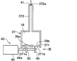
- the combination of the pressurized container and the drive mechanism of the first and third embodiments is replaced with a set of the pressurized container 37 and the drive mechanism 43 shown in FIG.
- the target to be replaced with the set of the pressurized container 37 and the drive mechanism 43 is the set of the pressurized container 17 and the drive mechanism 19.
- the target to be replaced with the set of the pressurized container 37 and the drive mechanism 43 is any one of the set of the pressurized container 17 and the drive mechanism 19 and the set of the pressurized container 17A and the drive mechanism 19A. Either one or both are acceptable.
- the pressurized container 37 of the present embodiment includes a large diameter portion 371 and a small diameter portion 372.
- the large-diameter portion 371 and the small-diameter portion 372 are connected to each other, and the small-diameter portion 372 is closer to the attachment target side than the large-diameter portion 371.
- the attachment target is the branch channel 13a if applied to the first embodiment, and is one or both of the branch channel 13a and the branch channel 13b if applied to the third embodiment.
- connection between the pressurized container 37 and the lower end of the attachment target is realized by connecting the open end 372a on the upper side (that is, the attachment target side) of the small diameter portion 372 with the lower end of the attachment target.
- the open end 372a is closed by an elastic film 41 made of an elastic body.
- the outer edge portion of the elastic film 41 is fixed to the open end 372a. Further, the lower surface of the elastic film 41 is in contact with the working liquid 18. Further, the upper surface of the elastic film 41 is in contact with the defoaming target liquid. Portions other than the outer edge portion of the elastic film 41 can be reciprocally displaced in the vertical direction with respect to the pressurized container 37 and the attachment target.
- This elastic film 41 liquid-tightly seals the upper end of the pressurized container 37. Therefore, the working liquid 18 in the pressurized container 37 does not leak from the open end 372a of the small diameter portion 372.
- the attachment target and the small diameter portion 372 are not in communication with each other, and the elastic film 41 partitions the attachment target and the pressurized container 37.
- the working liquid 18 in the pressurized container 37 can bias the defoaming target liquid in the attachment target via the elastic film 41 and the elastic film 14 on the main container 3 side.
- the elastic film 41 corresponds to a partition.
- Two separate open end portions 371a and 371b are formed on the lower end side of the large diameter portion 371.
- An elastic film 39a made of an elastic body is attached to the inner wall of the open end 371a.
- An elastic film 39b made of an elastic body is attached to the inner wall of the open end 371b.
- the outer edge portion of the elastic film 39a is fixed to the open end 371a. Further, the outer edge portion of the elastic film 39b is fixed to the opening end portion 371b. Further, the upper side surfaces of the elastic films 39 a and 39 b are in contact with the working liquid 18. Portions other than the outer edge portions of the elastic films 39a and 39b can be reciprocally displaced in the vertical direction with respect to the pressurized container 37 independently of each other.
- the elastic film 39a is supported by the opening end 371a and can be reciprocated
- the elastic film 39b is supported by the opening end 371b and can be reciprocated.
- the elastic films 39a and 39b seal the lower end of the pressurized container 37 in a liquid-tight manner. Therefore, the working liquid 18 in the pressurized container 37 does not leak from the lower end of the pressurized container 37.
- the opening area of the opening end 371a is sufficiently larger than the opening area of the opening end 372a on the upper end side of the small diameter portion 372.
- the opening area of the opening end 371b is also sufficiently larger than the opening area of the opening end 372a.
- the opening area of the opening end 371a and the opening area of the opening end 371b may be the same or different.
- the three openings of the pressurized container 37 are liquid-tightly sealed by the elastic films 41, 39a, 39b as described above, and the inside of the pressurized container 37 is filled with the working liquid 18.
- the components of the working liquid 18 are the same as those in the first embodiment.
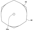
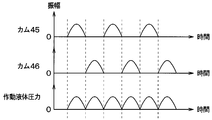
- the drive mechanism 43 for displacing the elastic films 39 a and 39 b is composed of a motor 44 and two cams 45 and 46 attached to the output shaft 44 a of the motor 44. As shown in FIG. 9, the cams 45 and 46 have the same shape and both have three peaks, but the phases of both are shifted by 60 degrees. The cam 45 is in contact with the lower surface of the elastic film 39a, and the cam 46 is in contact with the lower surface of the elastic film 39b.
- the detailed shapes of the outer peripheral surfaces (that is, the cam surfaces) of the cams 45 and 46 that come into contact with the elastic films 39a and 39b are as shown by the solid lines in FIGS.
- a cut surface obtained by cutting the outer peripheral surfaces of the cams 45 and 46 along a cross section perpendicular to the rotation axis of the cams is hereinafter referred to as an outer peripheral line of the cams 45 and 46.
- the following description of the shape of the outer peripheral lines of the cams 45 and 46 is valid for the outer peripheral lines obtained by cutting the outer peripheral surfaces of the cams 45 and 46 in any cross section perpendicular to the rotation axis of the cams.
- the minimum displacement portion L having the smallest distance from the rotation center S of the cams 45, 46 has three angular ranges ⁇ 1, ⁇ 3 in the circumferential direction as viewed from the shaft centers of the cams 45, 46. , ⁇ 5 exists throughout.
- a continuous portion of the outer peripheral lines of the cams 45 and 46 that is larger in distance from the rotation center S than the lowest displacement portion L is a high displacement portion.
- the maximum displacement portion H having the largest distance from the rotation center S among the outer peripheral lines of the cams 45 and 46 is located at each of the center position of the angle range ⁇ 2, the center position of the angle range ⁇ 4, and the center position of the angle range ⁇ 6. Exists. These three highest displacement portions H correspond to the peaks of the cams 45 and 46.
- intersection of the half line and the tangent line (for example, tangent line T1) in contact with the outer peripheral line at one end (for example, end Sa) of the high displacement portion is defined as the first intersection.
- the intersection point P1 corresponds to the first intersection point corresponding to the half line Mp
- the intersection point Q1 corresponds to the first intersection point corresponding to the half line Mq.
- intersection of the half line and the tangent line (for example, tangent line T2) in contact with the outer peripheral line at the other end (for example, the end Sb) of the high displacement portion is defined as the second intersection point.
- the intersection point P2 corresponds to the second intersection point corresponding to the half line Mp
- the intersection point Q2 corresponds to the second intersection point corresponding to the half line Mq.
- intersection of the high displacement part and the half line be the third intersection.
- the intersection point P3 corresponds to the third intersection point corresponding to the half line Mp
- the intersection point Q3 corresponds to the third intersection point corresponding to the half line Mq.
- the first intersection point P1 and the third intersection point P3 coincide.
- the first intersection point Q1 and the second intersection point Q2 also coincide.
- intersections P1, P2, and P3 there is a predetermined relationship between the first intersection, the second intersection, and the third intersection (for example, intersections P1, P2, and P3) in the same set. It is established. Specifically, the shorter of the straight line distance from the rotation center S to the first intersection and the straight line distance from the rotation center to the second intersection, the relationship of more than the straight line distance from the rotation center S to the third intersection is established. ing.
- the shorter one of the first intersection P1 and the second intersection P2 from the rotation center S is the first intersection P1.
- the linear distance from the rotation center S to the first intersection point P1 is the same as the linear distance from the rotation center S to the third intersection point P3.
- the tangent line T1 and the outer peripheral lines of the cams 45 and 46 coincide on the half line Mp.
- the tangent line T1 or tangent line T2 and the outer peripheral lines of the cams 45 and 46 coincide with most of the lowest displacement part excluding the highest displacement part H and its very vicinity.
- the first intersection point Q1 and the second intersection point Q2 have the same linear distance from the rotation center S. Further, the linear distance from the rotation center S to the first intersection Q1 and the second intersection Q2 is longer than the linear distance from the rotation center S to the third intersection Q3. In this case, the outer peripheral lines of the cams 45 and 46 are closer to the rotation center S than either of the tangents T1 and T2 on the half line Mq.
- the cams 45 and 46 have such an outer peripheral surface shape, the contact between the cams 45 and 46 and the lower surfaces of the elastic films 39a and 39b can always be maintained. Specifically, as shown in FIG. 12, the highest displacement portion H of the cams 45, 46 from the state where the lowest displacement portion L is in contact with the lower surfaces of the elastic films 39a, 39b (the rotation angle of the cams 45, 46 is ⁇ 36 °).
- the displacement of the elastic films 39a and 39b in the large diameter portion 371 is amplified and exerted on the elastic film 41 of the small diameter portion 372.
- the timing at which the cam 45 biases the elastic film 39a toward the working liquid 18 is different from the timing at which the cam 46 biases the elastic film 39b toward the working liquid 18.
- the pressurized container 37 corresponds to a basic pressurized container
- the elastic film 39a corresponds to a basic movable part
- the elastic film 39b corresponds to an additional movable part.
- the lower open end 371a of the large diameter portion 371 corresponds to a basic support portion
- the open end 371b corresponds to an additional support portion.
- the open end 372a on the upper side of the small diameter portion 372 corresponds to the basic connection portion.
- the working liquid 18 corresponds to a basic working liquid.
- the cam 45 corresponds to a basic cam
- the cam 46 corresponds to an additional cam.
- this invention is not limited to above-described embodiment, In the range described in the claim, it can change suitably. Further, the above embodiments are not irrelevant to each other, and can be combined as appropriate unless the combination is clearly impossible. In each of the above-described embodiments, the elements constituting the embodiment are not necessarily essential unless explicitly stated as essential and clearly considered essential in principle. Further, in each of the above embodiments, when numerical values such as the number, numerical value, quantity, range, etc. of the constituent elements of the embodiment are mentioned, it is clearly limited to a specific number when clearly indicated as essential and in principle. The number is not limited to the specific number except for the case.
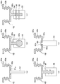
- the vibrator is a vibrator 51 made of metal, hard resin, or the like and having a rod shape and a disk portion 51a at the tip.
- the elastic film T and the vibrator 51 are connected by embedding the disk portion 51a in the elastic film T made of rubber or resin.
- a connecting portion 52 integrally formed with the elastic film T is connected to the lower surface of the elastic film T such as rubber or resin. Then, the elastic film T and the vibrator 53 are connected by embedding the spherical portion 52a of the connecting portion 52 in the vibrator 53 made of metal, hard resin, or the like.
- a rod-like connecting portion 54 integrally formed with the elastic film T is connected to the lower surface of the elastic film T such as rubber or resin. And the lower end of the connection part 54 is embed
- a screw or O-ring 56 is assembled to one or both of the connecting portion 54 and the vibrator 55 so that the connecting portion 54 does not come off from the vibrator 55.
- a connecting portion 57 having a rod shape and a thread is connected to the lower surface of the elastic film T such as rubber, resin, metal, composite material (glass fiber + resin, carbon fiber + resin, etc.). To do.
- the connecting portion 57 is integrally formed with the elastic film T.
- An internal thread is formed on the vibrator 58 made of metal or hard resin. As the connecting portion 57 and the vibrator 58 are screwed together, the elastic film T and the vibrator 58 are connected.
- a through hole 59 is provided in the central portion of the elastic film T such as rubber or resin, and the vibrator 60 made of metal, hard resin, or the like has a neck portion that matches the through hole 59.
- 60a and retaining disc 60b are provided.
- the elastic membrane T and the vibrator 60 are connected by fitting the neck 60 a into the through hole 59.
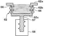
- a bellows 62 including an outer peripheral ring portion 62a, a trunk portion 62b, and a disc portion 62c is used instead of the piston C.
- the outer peripheral ring part 62a, the body part 62b, and the disk part 62c may be integrally formed of the same material (for example, rubber or resin), or may be formed by assembling members of different materials.
- the bellows 62 corresponds to the elastic film T in FIG.
- the barrel portion 62b Since the barrel portion 62b has a bellows shape, it is more easily expanded and contracted than the outer ring portion 62a and the disc portion 62c.
- a plurality of convex portions convex on the outer peripheral side and a plurality of concave portions convex on the inner peripheral side are alternately arranged one by one along the extending direction of the body portion 62b. The arranged shape.
- the outer ring part 62a is fixed to the lower opening end of the large diameter part.
- the upper opening end of the trunk portion 62b is fixed to the inner peripheral edge portion of the outer peripheral ring portion 62a.
- the lower opening end of the body part 62b is fixed to the outer peripheral edge part of the disk part 62c.
- the disk part 62c is a film that has a disk shape and is not easily deformed.
- the disk portion 62c is connected to the vibrator in the same manner as in each example of FIG.
- the raising / lowering change of the vibrator causes the body 62 b to expand and contract. Since the expansion / contraction deformation of the trunk portion 62b acts on the working liquid 18 in the bellows 62, the same operational effects as those of the pressurized container shown in the first to fourth embodiments can be obtained.
- the disk portion 62c may be a thin film that is easily deformed.
- the vibrator is connected to the elastic film T and the bellows 62. Therefore, the elastic film T and the bellows 62 follow the vibrator with high responsiveness when the vibrator is raised and lowered. Therefore, when the vibrator is connected to the elastic film T and the bellows 62, the behavior of the elastic film T and the bellows 62 can be controlled in more detail than when the vibrator is not connected. For example, it is also easy to change the amount of displacement of the elastic film T with the sine curve over time, instead of controlling the cam rotation, with a triangular wave.
- the flexible structural portions such as the elastic films 39a and 39b shown in the fifth embodiment and the bellows 62 shown in FIG. 15 may be swelled by the pressure when the pressure of the working liquid 18 increases. Examples of countermeasures are shown in FIGS.
- FIG. 16 shows an example in which swelling preventing members 65a and 65b made of hard resin or the like are attached to the lower side of the elastic films 39a and 39b shown in the fifth embodiment, respectively.
- the bulge preventing members 65a and 65b have a flat plate shape with a hole in the center.
- the outer peripheral edge part of the swelling prevention members 65a and 65b is being fixed to the opening edge part 371a and 371b, respectively.
- the cams 45 and 46 can pass through the holes at the center of the swelling preventing members 65a and 65b, respectively.
- the elastic film 39a is pressed by the cam 45 and pushed into the working liquid 18 side, while the elastic film 39b is in a state where the force from the cam 46 is relaxed.
- the elastic film 39b is in contact with and supported by the bulge preventing member 65b, and the elastic film 39b is prevented from bulging below the preventing member 65b. Therefore, the possibility that the pushing force by the cam 45 is canceled by the swelling of the elastic film 39b is reduced.
- the elastic film 39b is pressed by the cam 46 and pushed into the working liquid 18 side, while the elastic film 39a is in a state where the force from the cam 46 is relaxed.
- the elastic film 39a contacts and is supported by the bulge preventing member 65a, and the elastic film 39a is prevented from bulging below the bulge preventing member 65a. Therefore, the possibility that the pushing force by the cam 46 is canceled by the swelling of the elastic film 39a is reduced.
- FIG. 17 shows a structure in which a ring 66 for preventing swelling is attached to the outer periphery of a plurality of concave portions of the body portion 62b of the bellows 62 shown in FIG.
- a ring 66 prevents the concave portion from expanding to the outer peripheral side due to the pressure of the working liquid 18. If the concave portion can be prevented from expanding to the outer peripheral side, the vibration of the vibrator can be reliably transmitted by the working liquid 18.
- the number of sets of branch channels and small-diameter portions is not limited to two, but can be set to three or more, for example, depending on the length of the main channel 3a.
- the drive source of the drive mechanism is not limited to a combination of a motor and a cam, and various vibration generators such as various vibrators (electrically driven, air driven) and speaker systems according to the required amplitude, frequency, and excitation force. Can be used.
- the drive mechanism 19 that is the cam-type vibration generator in the first embodiment may be replaced with a drive mechanism 100 as shown in FIG.
- the drive mechanism 100 is a vibration generation source.
- the drive mechanism 19 applies vibration to the piston C by vibrating in contact with the piston C.
- the piston C to which this vibration is applied is displaced up and down like the first embodiment.
- the drive mechanism 100 may be a vibration generator mechanism described in Patent Document 3.
- the vibration generator mechanism includes a storage box and a vibration force varying device for generating vibration.
- the storage box is directly or indirectly connected to the piston C.
- the vibration generation variable device for generating vibration is a circular motion generator.
- the vibration generating variable force generator includes a first shaft, a second shaft, a female threaded cylinder, a first eccentric weight, a second eccentric weight, a rotating means, and a forward / backward means linked to the second shaft.
- the first shaft is rotatably supported on the storage box.
- the second shaft is slidably connected to the first shaft on the same axis as the first shaft, and rotates synchronously with the first shaft.
- the female screw cylinder is screwed into a threaded portion provided around the second shaft, is rotatably supported by the storage box, and is stopped from moving in the axial direction.
- the first eccentric weight is a fan-shaped weight fixed to the first shaft
- the second eccentric weight is a fan-shaped weight fixed to the female screw cylinder of the second shaft.
- the rotation means is linked to the first axis
- the advance / retreat means is linked to the second axis.
- the second shaft, the female screw cylinder, the first eccentric weight, and the second eccentric weight are rotated in synchronization with the first shaft. Vibrations are generated by this rotation, and the vibrations are transmitted to the piston C through the storage box. As a result, the piston C is displaced up and down.
- the amplitude of vibration generated by the rotation of the first eccentric weight and the second eccentric weight is determined according to the phase difference between the first eccentric weight and the second eccentric weight.
- the phase difference is a phase difference between the first eccentric weight and the second eccentric weight in the rotation direction of the first axis and the second axis.
- the amplitude of the vertical displacement of the piston C for maintaining the defoaming performance of the continuous bubble removing device 1 is different for each defoaming target liquid.
- the cam-type drive mechanism 19 as in the first embodiment in order to change the amplitude, the continuous bubble removing device 1 must be temporarily stopped and the cam 21 must be replaced.
- the same number of cams 21 as the number of amplitudes required depending on the type of liquid to be defoamed must be prepared.
- the amplitude is changed to an arbitrary value by causing the linear movement in the axial direction of the second axis by the advancing / retreating means during operation of the continuous bubble removing device 1. Can do. Therefore, the optimum amplitude can be set without preparing a large number of drive mechanisms 100.
- the drive mechanism 100 may be a vibration generation source other than the vibration generator mechanism described in Patent Document 3.
- the drive mechanism 100 may be a vibration generation source including a compressed air driven vibrator.
- a volatile and flammable solvent may be used as the defoaming target liquid.
- the continuous bubble removing device 1 is required to have an explosion-proof specification.
- the compressed air drive type vibrator can take an explosion-proof measure relatively inexpensively as compared with the electric vibration generator.
- the drive mechanism 100 described above is an alternative to the drive mechanism 19 of the second embodiment, the drive mechanisms 19 and 19A of the third embodiment, and the drive mechanism 19B of the fourth embodiment as well as the first embodiment. May be used as
- the pressure of the high-pressure microfeeder 5 is set to about 0.4 to 5 atmospheres, but it may be less than or more than this.
- the preferable pumping pressure is related to the size of the bubble and the ability of the vibration amount converter. That is, since the large bubbles easily contract, even if the pumping pressure of the high pressure microfeeder 5 is low, the defoaming effect of the large bubbles can be obtained.
- the drive mechanism is a mechanical mechanism using a cam, the vibration generation capability is increased, and the bubbles can be expanded and contracted even when the pressure of the high pressure microfeeder 5 is high, so that a defoaming effect can be obtained. it can.
- the sample liquid (highly viscous fluid) used for explanation in each embodiment is a 0.800 wt% sodium polyacrylate aqueous solution.
- the sample liquid may be any liquid as long as the viscosity of the solution is lowered by shearing.
- the sample liquid is not limited to a liquid whose viscosity is lowered by shear in the entire range of the shear rate, and may be a liquid whose viscosity is lowered by shear in a partial range of the shear rate. That is, it is only necessary that the viscosity of the sample liquid is lowered by shear within the range of the shear rate generated in the vicinity of the bubbles. Accordingly, a non-Newtonian fluid, a Bingham plastic fluid, or the like is suitable as the solution.
- the defoaming effect according to the above embodiment can be expected even when the viscosity is close to Newtonian fluid that does not depend much on shear.
- examples of the viscous fluid that can be expected to have a defoaming effect according to the above-described embodiment include a paint, a coating agent, a polymer, a paste, and a slurry.
- the elastic film 41, the elastic films 14, 14A, 141, 142, the pistons E, E1, E2, and EA in the above embodiment are not essential components.
- the main container 3 (branch channel 13a and the like) and the small diameter portion of the pressurized container may be directly connected.
- the defoaming target liquid and the working liquid are the same type of liquid.
- the present invention is an open cell removal method and a continuous cell removal apparatus for removing bubbles from a liquid passing through the container as described in the above embodiments and the like, but the present invention is, for example, Japanese Patent Application Laid-Open No. 2007-54680. It is also possible to apply to syringes (simply sealed containers) that do not allow liquid to circulate as described in the publication. That is, the syringe is filled with a liquid, and the pressurized container is connected to one place or a plurality of places while the liquid is stopped in the syringe (that is, the liquid does not pass through the syringe). Then, the pressure applied to the bubbles in the container may be changed up and down repeatedly. Even in that case, the same effect can be obtained.
- cam of the first to fourth embodiments may be replaced with the cam 45 used in the fifth embodiment.
- the branch channel 13b, the pressurized container 17A, the elastic membrane 14A, the piston EA, the piston CA, and the drive mechanism 19A shown in FIG. 6 may be added to the continuous bubble removing device 12 shown in FIG. . Further, in the configuration added as such, the drive mechanisms 19 and 19A may be replaced with the drive mechanism 19B of FIG.
- the large-diameter portion 291, the piston C, and the drive mechanism 19 may be replaced with the large-diameter portion 371, the elastic films 39 a and 39 b, and the drive mechanism 43 in FIG. Good.
- the sizes of the angle ranges ⁇ 2, ⁇ 4, and ⁇ 6 shown in FIG. 10 may all be the same, or only two may be the same. One may be different, or all three may be different from each other.
- the sizes of the angle ranges ⁇ 2, ⁇ 4, and ⁇ 6 do not match, the displacement modes of the elastic films 39a and 39b generated by the constant speed rotation of the cams 45 and 46 are uneven between the angle ranges ⁇ 2, ⁇ 4, and ⁇ 6. become.
- the number of high displacement portions formed on each of the cams 45 and 46 is three.
- the number of high displacement portions formed in each of the cams 45 and 46 is not limited to three, and may be one, two, or four or more.
- each of the pressurizing containers 17, 17A, 27, and 37 in the above embodiments may be changed so that the opening area is constant regardless of the position.
- the pressurized container may be discarded, and the pistons C, CA, E, EA, E1, E2, and the elastic films 39a, 39b may be directly connected to the main container 3.
Landscapes
- Chemical & Material Sciences (AREA)
- Chemical Kinetics & Catalysis (AREA)
- Life Sciences & Earth Sciences (AREA)
- Hydrology & Water Resources (AREA)
- Engineering & Computer Science (AREA)
- Environmental & Geological Engineering (AREA)
- Water Supply & Treatment (AREA)
- Organic Chemistry (AREA)
- Degasification And Air Bubble Elimination (AREA)
Abstract
【課題】気泡除去のための装置が大型化することを抑制しつつ、気泡の除去速度を向上させる。 【解決手段】連続気泡除去方法が、主容器3と、主容器に接続すると共に作動液体18を収容する与圧容器17と、与圧容器に対して変位可能に取り付けられる可動部Cと、を用意する手順と、気泡を含んだ脱泡対象液体を主容器に流通させる手順と、可動部を、与圧容器の支持部171aにて支持しながら往復変位させることにより、作動液体を介して、与圧容器において支持部よりも主容器側にある接続部172aによって囲まれた領域から、脱泡対象液体を反復的に加圧および減圧し、それにより気泡の体積を反復的に減少および増加させる手順と、を備える。支持部の開口面積は、接続部の開口面積よりも大きい。
Description
本発明は、液体に含まれる気泡を除去する連続気泡除去方法、および液体に含まれる気泡を除去する連続気泡除去装置に関するものである。
高粘性流体の気泡の除去は、その粘性のため、容易ではなく、さまざまな気泡除去方法が提案されてきた。例えば、特許文献1に記載の気泡除去技術では、入口から容器に液体が流入し、容器の容積が変化して容器内の加圧と減圧とが反復的に行われる。これにより、液体に含まれる気泡の体積が反復的に減少および増加し、その結果、気泡の周囲の液体に剪断が生じる。この剪断により、気泡の周囲の液体の粘度が低下し、浮力による気泡の上昇速度が上がる。そして、上昇した気泡が容器の気泡出口へ導かれ、気泡が除かれた液体は液体出口から容器外に流出する。このようにして、液体から気泡が連続的に除去される。
また、特許文献2に記載の気泡除去技術では、容器の複数箇所から容器内の加圧と減圧とが行われる。これにより、特許文献1の技術に対して、気泡の自然上昇速度が増加し気泡の除去効率が向上する。
特許文献1、2のような技術において、液体に含まれる気泡の除去速度をさらに上げる方法としては、容器の一箇所から及ぼす加圧と減圧の変化量を大きくする改良方法がある。
しかし、本願の発明者の検討によれば、そのような改良方法を実現するためには、加圧および減圧のための機構の剛性を大幅に上げる必要が生じる。その結果、気泡除去のための装置が大型化するという問題がある。
本発明は上記点に鑑み、気泡除去のための装置が大型化することを抑制しつつ、気泡の除去速度を向上させることを目的とする。
上記目的を達成するための連続気泡除去方法は、主容器(3)と、前記主容器に接続すると共に基本作動液体を収容する基本与圧容器(17、27、37)と、基本与圧容器に対して変位可能に取り付けられる基本可動部(C、39a)と、を用意する手順と、気泡を含んだ脱泡対象液体を前記主容器に流通させる手順と、前記基本可動部を、前記基本与圧容器の基本支持部(171a、291a、371a)にて支持しながら往復変位させることにより、前記基本作動液体を介して、前記基本与圧容器において前記基本支持部よりも前記主容器側にある基本接続部(172a、292a、372a)によって囲まれた領域から、前記脱泡対象液体を反復的に加圧および減圧し、それにより前記気泡の体積を反復的に減少および増加させる手順と、を備える。そして、前記基本支持部の開口面積は、前記基本接続部の開口面積よりも大きい。
また、上記目的を達成するための連続気泡除去装置は、気泡を含んだ脱泡対象液体が流通する主容器(3)と、前記主容器に接続すると共に基本作動液体を収容する基本与圧容器(17、27、37)と、前記基本与圧容器に対して変位可能に取り付けられる基本可動部(C、39a)と、を備え、前記基本与圧容器は、前記基本可動部が前記基本与圧容器に対して往復変位する際に前記基本可動部を支持する基本支持部(171a、291a、371a)と、前記基本支持部よりも前記主容器側にあって前記主容器に接続する基本接続部(172a、292a、372a)とを備え、前記基本可動部は、前記基本支持部に支持されて前記基本与圧容器に対して往復変位することにより、前記基本与圧容器に収容された前記基本作動液体に反復的に力を印加し、前記基本作動液体は、前記基本可動部の往復変位に伴って反復的に力を受けることにより、前記基本接続部によって囲まれた領域から、前記脱泡対象液体を反復的に加圧および減圧し、前記脱泡対象液体が前記基本作動液体によって反復的に加圧および減圧されることで、前記脱泡対象液体に含まれる前記気泡の体積が反復的に減少および増加し、前記基本支持部の開口面積は、前記基本接続部の開口面積よりも大きい。
このように、基本可動部の往復変位に応じた力が脱泡対象液体に伝達される経路である基本接続部の開口面積よりも基本可動部を支持する基本支持部の開口面積の方が大きい。したがって、可動部の変位の振幅を抑えながらも、基本接続部から脱泡対象液体に印加する圧力を、基本与圧容器が無い場合に比べて、高めることができる。その結果、気泡除去のための装置が大型化することを抑制しながらも、気泡の除去速度を向上させることができる。
また、他の観点によれば、連続気泡除去装置は、気泡を含んだ脱泡対象液体が流通する主容器(3)と、基本可動部(C、39a)と、回転することで前記基本可動部を付勢して前記基本可動部を変位させる基本カム(21、45)とを備え、前記基本可動部は、前記基本カムによって付勢されて往復変位することにより、前記主容器内の前記脱泡対象液体を反復的に加圧および減圧し、前記脱泡対象液体が反復的に加圧および減圧されることで、前記脱泡対象液体に含まれる前記気泡の体積が反復的に減少および増加する。このようにカムを使用する方式は、従来よりも強い圧力振動を気泡へ伝えることができ、脱泡効果も向上する。
なお、上記および特許請求の範囲における括弧内の符号は、特許請求の範囲に記載された用語と後述の実施形態に記載される当該用語を例示する具体物等との対応関係を示すものである。
(第1実施形態)
以下、第1実施形態について説明する。図1に示すように、本実施形態の連続気泡除去装置1は、主容器3、高圧マイクロフィーダー5、電子天秤9a、9b、可変絞り弁11a、11b、11c、与圧容器17、駆動機構19等によって構成される。
以下、第1実施形態について説明する。図1に示すように、本実施形態の連続気泡除去装置1は、主容器3、高圧マイクロフィーダー5、電子天秤9a、9b、可変絞り弁11a、11b、11c、与圧容器17、駆動機構19等によって構成される。
主容器3には、1つの液体入口3bと2つの出口3c、3dが形成されている。出口3cは気泡および脱泡対象液体が流出する出口である。以下、出口3cを気泡出口という。出口3dは気泡が除去された後の脱泡対象液体が流出する出口である。以下、出口3dを液体出口という。
また、主容器3には、液体入口3bから気泡出口3cおよび液体出口3dに脱泡対象液体を送るための主流路3aと、当該主流路3aと連通しながら当該主流路3aから分岐して下に延びる枝流路13aとが設けられている。主流路3aおよび枝流路13aは、連続気泡除去装置1の作動時に、気泡を含んだ脱泡対象液体を収容し、当該脱泡対象液体で満たされる。
主流路3aにはサイトグラス6が装着されており、主流路3aにおける気泡の軌跡をサイトグラス6を通して目視等で確認可能である。また、液体入口3bから主流路3aに気泡生成用の電極8が挿入されている。電極8は定電圧発生装置10に接続されている。なお、サイトグラス6と、電極8と定電圧発生装置10については、気泡の分離効果を検証するために用いたものであり、連続気泡除去装置1に必須のものではない。連続気泡除去装置1の通常の使用においては、液体入口から主流路3a内に入る脱泡対象液体に、既に気泡が含まれている。
液体入口3bは、主流路3aの一方の端部に設けられている。液体入口3bは、可変絞り弁11aを介して高圧マイクロフィーダー5に接続されている。高圧マイクロフィーダー5は圧送部に該当する。
気泡出口3cは、主流路3aの他方の端部に設けられている。気泡出口3cは可変絞り弁11bを介して回収管15aに接続されている。回収管15aは可変絞り弁11bから流れ出てくる流体を、電子天秤9a上に載置された秤量用のビーカに導くための管路である。
また、主流路3aは、液体入口3bよりも下流かつ気泡出口3c、液体出口3dよりも上流において、下方通路3eと上方通路3fに分岐している。下方通路3eは上方通路3fよりも下方に分岐している。
下方通路3eの下流端が液体出口3dとなっており、上方通路3fの下流端が気泡出口3cとなっている。液体出口3dは可変絞り弁11cを介して回収管15bに接続されている。回収管15bは可変絞り弁11cから流れ出てくる流体を、電子天秤9b上に載置された秤量用のビーカに導くための管路である。
枝流路13aは、主流路3aの、下方通路3eと上方通路3fの分岐点よりも上流側から、下方に向かって分岐している。枝流路13aが主流路3aから分岐して延びる方向が下方向なのは、この枝流路13aに満たされる脱泡対象液体に気泡が入り込む可能性を低減するためである。
枝流路13aの下端には、弾性体から成る弾性膜14が取り付けられている。弾性膜14の外縁部は、枝流路13aの下端に固定されており、弾性膜14の上側面は、脱泡対象液体に接触する。弾性膜14の外縁部以外の部分は、枝流路13aに対して変位可能になっている。この弾性膜14が枝流路13aの下端を液密に封止しているので、主容器3内の脱泡対象液体が枝流路13aの下端より洩れ出ない。
また、枝流路13aの下端には与圧容器17が接続されている。与圧容器17は大径部171と小径部172とを有する。大径部171と小径部172は互いに連接されており、小径部172が大径部171よりも枝流路13a側にある。大径部171の開口面積は小径部172の開口面積よりも十分に大きい。
与圧容器17と枝流路13aの下端との接続は、小径部172の上側(すなわち枝流路13a側)の開口端部172aを枝流路13aの下端と連接させることで実現する。開口端部172aは、樹脂等から成るピストンEによって閉じられている。
ピストンEは、開口端部172aの内壁によって支持されている。ピストンEは、開口端部172aを液密に封止しているが、開口端部172aの内壁に対して摺動可能となっている。したがって、ピストンEは、開口端部172aの内壁に支持されながら、小径部172の軸方向X2に沿って往復変位が可能である。
また、ピストンEの上端面と弾性膜14の下端面が互いに接触した状態で、ピストンEと弾性膜14が軸方向X2に往復変位する。また、ピストンEの上端面の面積と弾性膜14の下端面の面積は概略同じである。
このように、枝流路13aと小径部172とは連通状態とならず、弾性膜14とピストンEが枝流路13aと与圧容器17とを仕切っている。しかし、与圧容器17内の作動液体18は、ピストンEおよび弾性膜14を介して枝流路13a内の脱泡対象液体を付勢することができる。ピストンEおよび弾性膜14は仕切体に該当する。
大径部171の下端側の開口端部171aの内壁にはピストンCがはめ込まれている。ピストンCは開口端部171aを液密に閉じているが、開口端部171aの内壁に支持されながら大径部171の軸方向X1(すなわち上下方向)に沿って前進変位および後退変位が可能である。
そして、大径部171の下端側の開口端部171aの開口面積は、小径部172の上端側の開口端部172aの開口面積よりも十分大きい。
与圧容器17の両開口は上記のようにピストンCとピストンEとによって液密に封止されており、与圧容器17の内部は作動液体18にて満たされている。作動液体18は、粘性が低く、蒸気圧が高く、沸点が高い液体であればよい。具体的には、作動液体18は、工作機械の切削油であってもよいし、サラダ油であってもよいし、シリコンオイルであってもよいし、水であってもよい。
ピストンCの下方には、ピストンCを上下に変位させるための駆動機構19が配されている。ピストンCの上方への変位は前進変位に相当し、下方への変位は後退変位に相当する。与圧容器17と駆動機構19とが加振量変換器を構成している。
駆動機構19は、駆動源となるモータ20、モータ20の出力軸20aに取り付けられるカム21、カム21によって昇降駆動される振動子22等で構成されている。振動子22に関わる詳細構造は図2に示すとおりである。振動子22は、下基部22aおよび押圧棒22bを有している。
押圧棒22bは、上下方向に伸びる棒形状の部材であり、支持枠23の上面23aに設けられた穴を貫通して上部を突出させている。押圧棒22bの上端部はピストンCに接触可能に配置されている。押圧棒22bの上端部はピストンCに常時連結されていてもよい。あるいは、押圧棒22bの上端部は、振動子22が上方に変位した場合にピストンCに接触し、振動子22が下方に変位した場合にピストンCから離れるようになっていてもよい。
押圧棒22bの下端部は、下基部22aに固定されている。下基部22aは、支持枠23の上面から下方に延伸するガイド24に対し、摺動可能に連結されている。振動子22はガイド24にガイドされながら上下に往復自在であり、その昇降軌道はガイド24の延伸方向に沿う。
また、振動子22の下基部22aと上面23aとの間には、圧縮コイルばね25が介装されている。圧縮コイルばね25は、下基部22aと上面23aとの間で、押圧棒22bを取り巻いている。このため振動子22は、圧縮コイルばね25によって下降方向に付勢されている。
振動子22の下基部22aの下側には、下基部22aに対して回転可能に、カムフォロア26が取り付けられている。より具体的には、カムフォロア26はローラおよび回転軸を有する。この回転軸は、下基部22aに対して回転摺動可能に、取り付けられている。回転軸の延伸方向は、上下方向に直交し、かつ、出力軸20aに平行である。
そして、この回転軸の一端に、円盤形状のローラが、回転軸に対して直交して、固定されている。回転軸とローラは一体的に回転する。ローラの外周は、カム21の外周面(すなわちカム面)に当接している。この当接は圧縮コイルばね25の付勢力によって維持される。
このような構成であるため、モータ20によってカム21を回転駆動し、カム21の山でカムフォロア26を押し上げれば振動子22が上昇変位し、カムフォロア26が圧縮コイルばね25の付勢力によってカム21の谷に追従すれば振動子22が下降変位する。この際、カムフォロア26全体がカムの回転に引き摺られて回転することにより、振動子22がカム21によって上下方向以外の方向に付勢される力の強さを低減することができる。
また、上述のように振動子22が上昇変位すると、押圧棒22bの上端部がピストンCを押し込んで上昇させる。また、押圧棒22bがピストンCに連結されている場合は、振動子22が下降変位すると押圧棒22bの上端部がピストンCを引き戻して下降させる。また、押圧棒22bがピストンCに連結されていない場合は、振動子22が下降変位すると押圧棒22bの上端部がピストンCから離れ、ピストンCは作動液体18から受ける圧力および自重によって下降変位する。
なお、押圧棒22bがピストンCに常に連結されている場合は、連結されていない場合よりも、押圧棒22bの上昇時にも下降時にも、ピストンCが押圧棒22bにより高い応答性で追従する。したがって、押圧棒22bがピストンCに常に連結されている場合は、連結されていない場合よりも、ピストンCの挙動をより詳細に制御できる。例えば、カム21の回転を制御して、ピストンCの変位量をサイン曲線的に経時変化させるのではなく、三角波的に経時変化させることも容易になる。
次に、本実施形態の連続気泡除去装置1による気泡除去の実証例を説明する。まず、本例で用いた試料液体(高粘性流体)は、0.800wt%ポリアクリル酸ナトリウム水溶液である。この試料液体の粘度曲線は図3に示すようになっている。図3からわかるように、本試料液体(0.800wt%ポリアクリル酸ナトリウム水溶液)は、剪断速度が非常に小さい場合には、253Pa・sの粘度を示すと共に、剪断速度(Shear rate)の増加に伴い粘度(Shear viscosity)が低下する性質(Shear thinning性)を有している。したがって、この試料液体は、剪断が生じると粘度が低下する液体である。
この試料液体が高圧マイクロフィーダー5にて主容器3の液体入口3bから主流路3a内に圧送される。本例では、高圧マイクロフィーダー5の圧送圧力が0.4~5気圧程度になっている。主容器3の液体入口3bから主流路3a内に送られた試料液体は、主流路3a(枝流路13aおよび下方通路3eを含む)の内部を満たしながら気泡出口3cおよび液体出口3dに向かって流れる。
このとき、可変絞り弁11a、11b、11cの弁開度が小さく絞られている。これは、可変絞り弁11a、11b、11cの流路抵抗を大きくして抵抗部として機能させるためである。可変絞り弁11b、11cの弁開度を調整することで、気泡出口3c側と液体出口3d側との流量比を設定することができる。
また、可変絞り弁11a、11b、11cの弁開度を非常に小さく絞っているので、可変絞り弁11a、11b、11cの流路抵抗は非常に大きくなる。これにより、主流路3aの内部の試料液体が減圧、加圧可能となる。高圧マイクロフィーダー5は、可変絞り弁11a、11b、11cの流路抵抗に抗して液体を圧送する。
当該試料液体が主流路3a内を液体入口3bから出口3c、3dに連続して流通している状態で、所定の時間だけ定電圧発生装置10に通電され、電極8より気泡が発生する。この結果、試料液体は、気泡を含んだ脱泡対象液体となる。そして、駆動機構19が連続して稼働される。
すると、モータ20がカム21を連続して回転させる。その結果、カムフォロア26を介してカム21によって付勢された振動子22は、反復的な昇降変位(すなわち往復変位)を行う。この振動子22の反復的な変位によってピストンCが反復的に昇降変位する。
この際、ピストンCは、開口端部171aに支持されて与圧容器17に対して昇降変位することにより、与圧容器17に収容された作動液体18に反復的に力を印加する。そして、作動液体18は、ピストンCの往復変位に伴って反復的に力を受けることにより、開口端部172aによって囲まれた領域において、ピストンEを与圧容器17に対して昇降変位させる。
つまり、ピストンCの昇降変位は、作動液体18に対しては、作動液体18を小径部172の開口端部172aから枝流路13a側に押し出し、引き戻す変位、すなわち小径部172内での作動液体18の反復的な往復運動変位として作用する。
そのため、ピストンEと弾性膜14が小径部172の開口端部172aおよび枝流路13aの下端部において反復的に往復変位する。振動子22の反復的な昇降変位、ピストンC、Eの反復的な昇降変位、作動液体18の反復的な往復運動変位は、いずれも、振動に相当する。
ピストンEおよび弾性膜14の往復変位は、開口端部172aによって囲まれた領域から、主容器3内の試料液体および気泡(特に、枝流路13a内およびその近傍の気泡)に作用し、試料液体および気泡に働く圧力を反復的に減少および増加させる。この際に、可変絞り弁11a、11b、11cが抵抗部として機能して、主流路3aの内部と外部との間での液体の流通に抵抗を与える。したがって、ピストンEおよび弾性膜14の往復変位に由来する圧力の昇降変化が効率よく気泡に働く。
このように、気泡に作用させる圧力を反復的に減少および増加させることで、気泡の体積を反復的に減少および増加させることができる。気泡の体積が反復的に増減変化すると、気泡の周囲の試料液体に剪断が生じる。その結果、気泡の周囲の試料液体の粘度が低下し、気泡が浮力により液体中にて高速に上昇する。
試料液体中にて上昇した気泡は、主流路3a内の液体の流れに伴って主流路3aの上端部を移動し、試料液体とともに気泡出口3cから可変絞り弁11bを経て回収管15aに流出する。
液体出口3dにつながる下方通路3eは、試料液体の流れに沿って斜め下方に向かう傾斜流路であることから、上述のように浮力で上昇した気泡が下方通路3eに入り込む可能性が低く、液体出口3dからは殆ど気泡を含まない液体が流出する。
このように、主流路3a内に脱泡対象液体を連続的に供給しながら、ピストンC等を介した脱泡対象液体への加圧および減圧を反復的に繰り返すことで、脱泡対象液体から気泡を連続的に除去することができる。
また、大径部171の開口端部171aの開口面積が小径部172の開口端部172aの開口面積を大きく上回る。言い換えれば、ピストンCの方向X1に直交する断面積がピストンEの方向X2に直交する断面積および弾性膜14の下面の面積を大きく上回る。
したがって、ピストンCを往復変位させたときの大径部171の開口端部171a側での作動液体18の変位量よりも小径部172の開口端部172aにおける作動液体18の変位量の方が大きい。その結果、ピストンEおよび弾性膜14の振幅はピストンCの振幅よりも大きくなる。これにより、主流路3aにおける枝流路13a近傍において、主容器3内の試料液体および気泡の圧力の変化量が大きくなり、気泡の体積の増減変化の量も増大する。したがって、気泡を上昇移動させて除去する効率が向上する。
また、与圧容器17は、ピストンCの振幅を増幅してピストンEおよび弾性膜14に伝えて、その振幅を大きくする効果を発揮するから、カム21が発生させる振動の振幅を変えずとも、ピストンEおよび弾性膜14の振幅をより大きくすることができる。
ピストンCとピストンEの振幅に関しては、以下の関係が成り立つ。
ΔVe=Se×Δhe
ΔVc=Sc×Δhc
ここで、ピストンCの上記断面積をSc、ピストンCの変位による与圧容器17の容積変化をΔVc、ピストンCの変位量をΔhc、ピストンEの上記断面積をSe、ピストンEの変位による主容器3の容積変化をΔVe、ピストンEの変位量をΔheとする。内部の作動液体18の体積は等しいので、ΔVc=ΔVeとなり、
Sc×Δhc=Se×Δhe
となる。したがって、
Δhe=(Sc/Se)×Δhc
であり、Se<ScであればΔhe>Δhcとなる。
ΔVe=Se×Δhe
ΔVc=Sc×Δhc
ここで、ピストンCの上記断面積をSc、ピストンCの変位による与圧容器17の容積変化をΔVc、ピストンCの変位量をΔhc、ピストンEの上記断面積をSe、ピストンEの変位による主容器3の容積変化をΔVe、ピストンEの変位量をΔheとする。内部の作動液体18の体積は等しいので、ΔVc=ΔVeとなり、
Sc×Δhc=Se×Δhe
となる。したがって、
Δhe=(Sc/Se)×Δhc
であり、Se<ScであればΔhe>Δhcとなる。
ピストンCを駆動するための駆動機構19の構成については上述した通りであるが、その作動の詳細を以下に説明する。まず、振動子22に振動を与えるためのカム21の形状は、図4に示す通りである。ただし、図4では、形状を分かりやすくするため山の高さを実際よりも30倍にしている。具体的には、山の高さが0.1mm(振幅としては0.05mm)、山の数は6、山の形状は変形正弦曲線である。ここで、ピストンCの断面積Sc=491mm2(直径25mm)、ピストンEの断面積Se=50mm2(直径8mm)であるので、増幅作用によってピストンEの変位量Δheは約1mm(振幅としては約0.5mm)となる。
振動を与える周波数は、本実施形態では、200Hzを用いたが、好ましくは4000Hz以下の低周波であればよい。例えば150Hzでもよい。すなわち、剪断により気泡近傍の流体粘性が下がるように、振動の周波数、圧力変動幅、位相が設定される。
比較例として、振動発生源として、スピーカー方式の振動発生装置を用いた国際公開第2013/021849号の装置を用いる。この振動発生装置の能力は無負荷時でも200Hzで最大振幅は0.4mmであり、負荷時にはこれよりも更に小さくなる。本例のカム方式と、比較例のスピーカー方式の実験条件は次の表1の通りである。

ここで、流量比は総流量に対する液体出口3dからの流出量の割合である。
次に、気泡の膨張、収縮を評価する。体積収縮率α[%]は次式で示される。
α=(Vmax-Vmin)/Vmin×100
気泡径r=r0+A×sin(ωt)、
気泡表面速度u=dr/dt=A×ω×cos(ωt)、
半径速度の微分値ur=du/dr=(1/Δt)[(r|t/r|t+Δt)2-1]とすると、剪断速度γ_dot[s-1]は次式で定義される。
γ_dot=(2S:S)1/2=(2ur 2+4u2/r2)1/2
ここで、Vmaxは気泡の最大体積、Vminは気泡の最小体積、r0、A、ωは定数、Sは変形速度テンソルである。また、r|tは時刻tにおける気泡径、r|t+Δtは時刻t+Δtにおける気泡径である。Δtは気泡径の振動の半周期の時間である。実験の結果、体積収縮率、剪断速度の比較結果は以下の表2の通りとなった。
α=(Vmax-Vmin)/Vmin×100
気泡径r=r0+A×sin(ωt)、
気泡表面速度u=dr/dt=A×ω×cos(ωt)、
半径速度の微分値ur=du/dr=(1/Δt)[(r|t/r|t+Δt)2-1]とすると、剪断速度γ_dot[s-1]は次式で定義される。
γ_dot=(2S:S)1/2=(2ur 2+4u2/r2)1/2
ここで、Vmaxは気泡の最大体積、Vminは気泡の最小体積、r0、A、ωは定数、Sは変形速度テンソルである。また、r|tは時刻tにおける気泡径、r|t+Δtは時刻t+Δtにおける気泡径である。Δtは気泡径の振動の半周期の時間である。実験の結果、体積収縮率、剪断速度の比較結果は以下の表2の通りとなった。

膨張・収縮による気泡径の変化のみに着目した収縮率では、カム方式はスピーカー方式の1.8倍の気泡径変化がみられ、剪断速度はより大きい値をとった。よって、カム方式はスピーカー方式と比べ、より強い圧力振動を気泡へ伝えることができており、脱泡効果も向上しているといえる。
このように、本実施形態では、ピストンCの面積がピストンEの面積よりも大きいため、振動子22の振幅を抑えながらも、強い圧力振動を試料液体および気泡に印加することができる。したがって、気泡除去のための駆動機構19が大型化することを抑制しつつ、気泡の除去速度を向上させることができる。
以上説明した通り、本実施形態では、連続気泡除去装置1を用意する手順と、気泡を含んだ脱泡対象液体を主容器3に流通させる手順とがある。そして、ピストンCを、大径部171の開口端部171aにて支持しながら往復変位させることにより、作動液体18を介して、小径部172の開口端部172aによって囲まれた領域から、脱泡対象液体を反復的に加圧および減圧する。それにより、気泡の体積を反復的に減少および増加させることができる。そして、大径部171の開口端部171aの開口面積は、小径部172の開口端部172aの開口面積よりも大きい。
このように、ピストンCの往復変位に応じた加圧および減圧が脱泡対象液体に伝達される経路である開口端部172aの開口面積よりも、ピストンCを支持する開口端部171aの開口面積の方が大きい。したがって、ピストンCの変位の振幅を抑えながらも、開口端部172aから脱泡対象液体に印加する圧力の振幅を、与圧容器17が無い場合に比べて、高めることができる。その結果、気泡除去のための駆動機構が大型化することを抑制しながらも、気泡の除去速度を向上させることができる。
また、弾性膜14が、主容器3の与圧容器17側の端部に取り付けられて脱泡対象液体を封止する。そして、ピストンEが、与圧容器17の開口端部172aに取り付けられ、作動液体18を封止する。
このようにすることで、主容器3と与圧容器17の間で作動液体および脱泡対象液体が漏れる可能性を低減することができる。そして、主容器3と与圧容器17の両方で封止が行われている。したがって、例えば、ピストンC、ピストンEを含むモジュールに不具合が発生し、当該モジュールを主容器3から取り外した場合にも、脱泡対象液体および作動液体18が洩れ出す可能性が低減される。
なお、本実施形態では、与圧容器17が基本与圧容器に相当し、ピストンCが基本可動部に相当する。また、大径部171の下側の開口端部171aが基本支持部に相当し、小径部172の上側の開口端部172aが基本接続部に相当する。また、作動液体18が、基本作動液体に相当する。また、カム21が基本カムに相当する。また、弾性膜14が主容器側封止体に相当し、ピストンEが接続部側封止体に相当する。
(第2実施形態)
以下、第2実施形態について説明する。本実施形態の連続気泡除去装置12の構成は図5に示す通りである。本実施形態の連続気泡除去装置12が第1実施形態の連続気泡除去装置1と共通する部分については、第1実施形態と同符号を付して説明を省略する。
以下、第2実施形態について説明する。本実施形態の連続気泡除去装置12の構成は図5に示す通りである。本実施形態の連続気泡除去装置12が第1実施形態の連続気泡除去装置1と共通する部分については、第1実施形態と同符号を付して説明を省略する。
図5に示すように、主容器3に主流路3a、液体入口3b、気泡出口3c、液体出口3dおよび枝流路13aが設けられている点は第1実施形態と共通である。本実施形態では更に、2本目の枝流路13bが、主容器3に設けられている。
枝流路13bは、主流路3aのうち、主流路3aと枝流路13aの分岐点よりも下流側、かつ、出口3c、3dよりも上流側において、主流路3aから分岐して下方に向かって伸びている。
枝流路13aの下端(すなわち与圧容器27側の端部)には、弾性体から成る弾性膜141が取り付けられている。弾性膜141の外縁部は、枝流路13aの下端に固定されており、弾性膜141の上側面は、脱泡対象液体に接触する。弾性膜141の外縁部以外の部分は、枝流路13aに対して変位可能になっている。この弾性膜141が枝流路13aの下端を液密に封止しているので、主容器3内の脱泡対象液体が枝流路13aの下端より洩れ出ない。
枝流路13bの下端(すなわち与圧容器27側の端部)には、弾性体から成る弾性膜142が取り付けられている。弾性膜142の外縁部は、枝流路13bの下端に固定されており、弾性膜142の上側面は、脱泡対象液体に接触する。弾性膜142の外縁部以外の部分は、枝流路13bに対して変位可能になっている。この弾性膜142が枝流路13bの下端を液密に封止しているので、主容器3内の脱泡対象液体が枝流路13bの下端より洩れ出ない。
枝流路13a、13bの下端には与圧容器27が接続されている。与圧容器27は1本の大径部291と2本の小径部292、293と1本の中継部294を有する。大径部291と2本の小径部292、293は中継部294を介して連接されている。小径部292、293の開口面積は互いに等しく、大径部291の開口面積は小径部292、293の開口面積よりも十分に大きい。
与圧容器27と枝流路13aの下端との接続は、小径部292の上側(すなわち枝流路13a側)の開口端部292aを枝流路13aの下端と連接させることで実現する。開口端部292aは、樹脂等から成るピストンE1によって閉じられている。
ピストンE1は、開口端部292aの内壁によって支持されている。ピストンE1は、開口端部292aを液密に封止しているが、開口端部292aの内壁に対して摺動可能となっている。したがって、ピストンE1は、開口端部292aの内壁に支持されながら、小径部292の軸方向X21に沿って往復変位が可能である。
また、ピストンE1の上端面と弾性膜141の下端面が互いに接触した状態で、ピストンE1と弾性膜141が軸方向X21に往復変位する。また、ピストンE1の上端面の面積と弾性膜141の下端面の面積は概略同じである。
このように、枝流路13aと小径部292とは連通状態とならず、弾性膜141とピストンE1が枝流路13aと小径部292とを仕切っている。しかし、与圧容器27内の作動液体18は、ピストンE1および弾性膜141を介して枝流路13a内の脱泡対象液体を付勢することができる。ピストンE1および弾性膜141は仕切体に該当する。
与圧容器27と枝流路13bの下端との接続は、小径部293の上側(すなわち枝流路13b側)の開口端部293aを枝流路13bの下端と連接させることで実現する。開口端部293aは、樹脂等から成るピストンE2によって閉じられている。
ピストンE2は、開口端部293aの内壁によって支持されている。ピストンE2は、開口端部293aを液密に封止しているが、開口端部293aの内壁に対して摺動可能となっている。したがって、ピストンE2は、開口端部293aの内壁に支持されながら、小径部293の軸方向X22に沿って往復変位が可能である。
また、ピストンE2の上端面と弾性膜142の下端面が互いに接触した状態で、ピストンE2と弾性膜142が軸方向X22に往復変位する。また、ピストンE2の上端面の面積と弾性膜142の下端面の面積は概略同じである。
このように、枝流路13bと小径部293とは連通状態とならず、弾性膜142とピストンE2が枝流路13bと小径部293とを仕切っている。しかし、与圧容器27内の作動液体18は、ピストンE2および弾性膜142を介して枝流路13b内の脱泡対象液体を付勢することができる。ピストンE2および弾性膜142は仕切体に該当する。
大径部291の下端側の開口端部291aにはピストンCがはめ込まれている。ピストンCは開口端部291aを液密に閉じているが、開口端部291aの内壁に支持されながら大径部291の軸方向X1に沿って前進変位および後退変位が可能である。
そして、大径部291の下端側の開口端部291aの開口面積は、小径部292の上端側の開口端部292aの開口面積よりも十分大きい。また、開口端部291aの開口面積は、小径部293の上端側の開口端部293aの開口面積よりも十分大きい。更には、開口端部291aの開口面積は、開口端部292aの開口面積と開口端部293aの開口面積の和よりも十分大きい。
与圧容器27の各開口は上記のようにピストンC、ピストンE1、ピストンE2によって液密に閉じられており、与圧容器27の内部は、第1実施形態と同じ作動液体18にて満たされている。ピストンCと駆動機構の19の関係は、第1実施形態と同じである。
第1実施形態と同様、振動子22が反復的な昇降変位を行う。この振動子22の反復的な変位によってピストンCが反復的に昇降変位する。
この際、ピストンCは、開口端部291aに支持されて与圧容器27に対して昇降変位することにより、与圧容器27に収容された作動液体18に反復的に力を印加する。そして、作動液体18は、ピストンCの往復変位に伴って反復的に力を受けることにより、開口端部292a、293aによって囲まれた領域において、ピストンE1、E2を与圧容器27に対して昇降変位させる。
つまり、ピストンCの昇降変位は、小径部292における作動液体18を開口端部292aから押し出し、引き戻す変位、すなわち小径部292内での作動液体18の往復運動変位として作用する。そのため、ピストンE1が小径部292の開口端部292aにおいて往復変位する。ピストンCの昇降変位は、同様に小径部293の作動液体18に対しても作用し、ピストンE2が小径部293の開口端部293aにおいて往復変位する。
ピストンE1、E2の往復変位は、開口端部292a、293aによって囲まれた領域から、主容器3内の脱泡対象液体および気泡(特に、枝流路13a、13b内およびその近傍の気泡)に作用し、気泡に働く圧力を反復的に昇降変化させる。この際に、可変絞り弁11a、11b、11cが抵抗部として機能するので、ピストンE1、E2の往復変位に由来する圧力の昇降変化が効率よく気泡に働く。すなわち、与圧容器27と駆動機構19とで加振量変換器が構成されている。
このように、気泡に作用させる圧力を反復的に昇降変化させることで、気泡の体積を反復的に増減変化させることができる。気泡の体積が反復的に増減変化すれば、気泡の周囲の液体に剪断が生じる。その結果、気泡の周囲の液体の粘度が低下して気泡が液体中にて高速に上昇する。
このときに、例えば枝流路13aの近くに存在する気泡が枝流路13aから及ぼされる圧力変化を吸収してしまって、そこから遠い位置の気泡にまでは十分に届かないことも考えられる。しかし、枝流路13bからも圧力変化が及ぼされるので、上記の遠い位置の気泡にはこちらが十分に作用する。このように、2本の枝流路13a、13bからの圧力変化を気泡に及ぼすことができるから、気泡除去の効果が向上する。
また、与圧容器27内における大径部291の開口端部291aから小径部292の開口端部292aまでの距離と、与圧容器27内における大径部291の開口端部291aから小径部293の開口端部293aまでの距離とは、同じである。したがって、ピストンE1、E2の往復変位が同じタイミング(すなわち、同じ周波数および位相)で行われるので、この点からも気泡除去の効果が向上する。液体中にて上昇した気泡の排出および気泡を含まない液体の回収は、第1実施形態と同様に行われる。
大径部291の開口端部291aの開口面積すなわちピストンCの方向X1に直交する断面積が小径部292、293の開口端部292a、293aの開口面積すなわちピストンE1、E2の方向X21、X22に直交する断面積の和を大きく上回る。したがって、ピストンCを往復変位させたときの大径部291側での作動液体18の変位量よりも小径部292、293における作動液体18の変位量の方が大きく、ピストンE1、E2の振幅はピストンCの振幅よりも大きくなる。これにより、主容器3内の圧力の変化量が大きくなり、気泡の体積の増減変化の量も増大するから、気泡を上昇移動させて除去する効率が向上する。
ピストンCとピストンE1、E2の振幅に関しては、以下の関係が成り立つ。すなわちピストンCの面積をSc、ピストンCの変位量をΔhc、ピストンE1の面積をSe1、ピストンE1の変位量をΔhe1、ピストンE2の面積をSe2、ピストンE2の変位量をΔhe2とし、Se1=Se2、Δhe=Δhe1=Δhe2、Sc>Se=Se1+Se2とすると、
Δhe=Δhc×(Sc/Se)
となる。なお、Se1=Se2、Δhe1=Δhe2の式は、成り立たない場合があってもよい。例えば、Se1>Se2、Δhe1<Δhe2であってもよく、あるいは、Se1<Se2、Δhe1>Δhe2であってもよい。
Δhe=Δhc×(Sc/Se)
となる。なお、Se1=Se2、Δhe1=Δhe2の式は、成り立たない場合があってもよい。例えば、Se1>Se2、Δhe1<Δhe2であってもよく、あるいは、Se1<Se2、Δhe1>Δhe2であってもよい。
与圧容器27は、ピストンCの振幅を増幅してピストンE1、E2に伝えて、その振幅を大きくする効果を発揮するから、カム21が発生させる振動の振幅を変えずとも、ピストンE1、E2の振幅をより大きくすることができる。
また、複数の振動源(上記実施形態ではピストンE1、E2)を、主容器3内の液体の流れの上流および下流に配置することで、入口から出口までの液体を送る流路(上記実施形態では主流路3a)を長くしても、容器内の各所に振動を効率良く(すなわち、減衰を抑えて)伝えることができる。したがって、入口から出口までの液体を送る流路を長くして、その流路の上流と下流に振動源を配置することで、気泡が圧力振動を充分受けつつ移動できる経路長を伸ばすことができ、ひいては、気泡の上昇量を大きくすることができる。
また、液体内に気泡が複数個存在した場合を想定すると、1つの振動源から印加された圧力振動は、その振動源に最も近い気泡の体積変化によって消費されてしまい、他の気泡まで充分届かなくなってしまう。つまり、1つの振動源から印加された圧力振動は、その振動源に最も近い気泡によって遮蔽されてしまう。これに対し、複数の振動源を用いて位置の異なる複数箇所(上流と下流であってもよいし、そうでなくてもよい)から主容器3内の液体に圧力振動を印加した場合は、液体内に気泡が複数個存在していても、それら複数個の気泡のそれぞれに充分な圧力振動を印加できる可能性が高くなる。
また、位置の異なる複数箇所(上流と下流であってもよいし、そうでなくてもよい)から主容器3内の液体に同周波数かつ同位相の圧力振動を印加した場合、振動源の異なる圧力振動が液体内で干渉し合うことになる。したがって、液体中の複数の位置において、異なるタイミングで圧力振動が印加されたのと同等の効果が局所的に実現すると考えられる。
なお、上記の例では、与圧容器27内における大径部291の開口端部291aから小径部292の開口端部292aまでの距離と、与圧容器27内における大径部291の開口端部291aから小径部293の開口端部293aまでの距離とは、同じである。しかし、必ずしもこのようになっておらずともよい。つまり、与圧容器27内における大径部291の開口端部291aから小径部292の開口端部292aまでの距離と、与圧容器27内における大径部291の開口端部291aから小径部293の開口端部293aまでの距離とは、異なっていてもよい。このようにすることで、ピストンE1、E2の振動を付与する位置を意図的に互いに異ならせることができる。
なお、本実施形態では、与圧容器27が基本与圧容器に相当し、ピストンCが基本可動部に相当する。また、大径部291の下側の開口端部291aが基本支持部に相当し、小径部292の上側の開口端部292aが基本接続部に相当し、小径部293の上側の開口端部293aが追加接続部に相当する。また、作動液体18が、基本作動液体に相当する。また、カム21が基本カムに相当する。また、弾性膜141、142が主容器側封止体に相当し、ピストンE1、E2が接続部側封止体に相当する。
(第3実施形態)
次に第3実施形態について説明する。本実施形態の連続気泡除去装置31は、図6に示す通り、第1実施形態の連続気泡除去装置1に対して、枝流路13b、与圧容器17A、駆動機構19A、ピストンCA、ピストンEA、弾性膜14A、作動液体18Aが追加されている。その他の部分の構成は、第1実施形態の連続気泡除去装置1と同じである。
次に第3実施形態について説明する。本実施形態の連続気泡除去装置31は、図6に示す通り、第1実施形態の連続気泡除去装置1に対して、枝流路13b、与圧容器17A、駆動機構19A、ピストンCA、ピストンEA、弾性膜14A、作動液体18Aが追加されている。その他の部分の構成は、第1実施形態の連続気泡除去装置1と同じである。
枝流路13bは、主流路3aのうち、主流路3aと枝流路13aの分岐点よりも下流側、かつ、出口3c、3dよりも上流側において、主流路3aから分岐して下方に向かって伸びている。
枝流路13bの下端(すなわち与圧容器17A側の端部)には、弾性体から成る弾性膜14Aが取り付けられている。枝流路13bの下端に対する弾性膜14Aの取り付け形態は、枝流路13aの下端に対する弾性膜14の取り付け形態と同じである。
枝流路13bの下端には、与圧容器17Aが接続されている。与圧容器17Aの形状および構成は、与圧容器17と同じである。具体的には、与圧容器17Aは、大径部171Aおよび小径部172Aを有し、大径部171Aは下側の開口端部171aAを有し、小径部172Aは上側の開口端部172aAを有する。そして、大径部171A、小径部172A、開口端部171aA、開口端部172aAの特徴および相互の関係は、大径部171、小径部172、開口端部171a、開口端部172aと同じである。
したがって、与圧容器17Aの小径部172Aにおける上側の開口端部172aAは、与圧容器17Aの大径部171Aにおける下側の開口端部171aAよりも、主容器3側にある。そして、開口端部172aAは、主容器3に接続する。
また、枝流路13bの下端に対する与圧容器17Aの取り付け構造は、枝流路13aの下端に対する与圧容器17の取り付け構造と同じである。このように、与圧容器17Aは、与圧容器17とは別の位置から主容器3に接続する。
また、ピストンEAの形状および材質は、ピストンEと同じである。また、ピストンEAの与圧容器17Aに対する取り付け形態は、ピストンEの与圧容器17に対する取り付け形態と同じである。また、ピストンEAの弾性膜14Aに対する接続形態は、ピストンEの弾性膜14に対する接続形態と同じである。
また、ピストンCAの与圧容器17Aに対する接続形態は、ピストンCの与圧容器17に対する接続形態と同じである。したがって、ピストンCAは、与圧容器17Aに対して変位可能に取り付けられる。また、ピストンCAは、与圧容器17Aに対して往復変位する際に、与圧容器17Aの大径部171Aにおける下側の開口端部171aAの内壁に、支持される。
作動液体18Aは、与圧容器17A内に収容され、与圧容器17A内において、ピストンCAとピストンEAの間で、ピストンCAとピストンEAによって封止されている。作動液体18Aの成分は、作動液体18と同じである。
ピストンCAを駆動するための駆動機構19Aの構成は、駆動機構19と同じである。具体的には、駆動機構19Aは、モータ20A、カム21A、振動子22Aを有し、モータ20Aは出力軸20aAを有する。そして、モータ20A、カム21A、振動子22A、出力軸20aAの特徴および相互の関係は、モータ20、カム21、振動子22、出力軸20aと同じである。また、駆動機構19Aの振動子22AとピストンCAの関係は、駆動機構19の振動子22とピストンCの関係と同じである。
このように、連続気泡除去装置31は、与圧容器17と駆動機構19とで構成されるものと、与圧容器17Aと駆動機構19Aとで構成されるものとの、2組の加振量変換器を備えている。
本実施形態の連続気泡除去装置31では、一方の加振量変換器(例えば与圧容器17と駆動機構19の組)だけを稼働させることが可能で、その場合の作用および効果は第1実施形態と同様となる。
また、2組の加振量変換器を両方とも稼働させれば第2実施形態と同様に、2本の枝流路13a、13bからの圧力変化を気泡に及ぼすことができる。したがってこの場合、第2実施形態と同様、気泡除去の効果が向上する。
2組の加振量変換器を両方とも稼働する際に、各駆動機構19、19Aのカム21、21Aの形状を変えたり、カム21、21Aの回転速度を変えたりすることで、ピストンC、CAの振幅、周波数、位相を互いに独立して任意に設定することができる。
したがって、ピストンE、EAおよび弾性膜14、14Aから主容器3に及ぼされる圧力変化の振幅、周波数、位相を互いに独立して任意に設定することができる。また、振幅、周波数、位相のいずれかを、またはすべてを同じくすることも可能である。
また、主容器3の異なる位置(枝流路13a、13b)から同一タイミングで(例えば、同一周波数かつ同一位相の連続振動で)主容器3の内部を減圧および加圧するだけでも、単一の位置から主容器3の内部を減圧および加圧する場合に比べて高い脱泡効果を得ることができる。
なぜなら、駆動機構19、19Aの性能等による限界から、1箇所から(例えば与圧容器17と駆動機構19の組により枝流路13aから)減圧および加圧するときの出力(体積変化量、加圧力等)には限界があるので、複数箇所から減圧および加圧すれば、全体としてはその限界を超えた出力で液体を減圧および加圧することができるからである。
なお、本実施形態では、与圧容器17が基本与圧容器に相当し、ピストンCが基本可動部に相当する。また、与圧容器17Aが別与圧容器に相当し、ピストンCAが別可動部に相当する。また、与圧容器17においては、大径部171の下側の開口端部171aが基本支持部に相当し、小径部172の上側の開口端部172aが基本接続部に相当する。また、与圧容器17Aにおいては、大径部171Aの下側の開口端部171aAが別支持部に相当し、小径部172Aの上側の開口端部172aAが別接続部に相当する。また、作動液体18が基本作動液体に相当し、作動液体18Aが別作動液体に相当する。また、カム21、21Aが基本カムに相当する。また、弾性膜14、14Aが主容器側封止体に相当し、ピストンE、EAが接続部側封止体に相当する。
(第4実施形態)
次に第4実施形態について説明する。本実施形態は、第3実施形態に対して、2つの駆動機構19、19Aを1つの駆動機構19Bに置き換えたものである。本実施形態の駆動機構以外の部分の構成は第3実施形態と同じである。
次に第4実施形態について説明する。本実施形態は、第3実施形態に対して、2つの駆動機構19、19Aを1つの駆動機構19Bに置き換えたものである。本実施形態の駆動機構以外の部分の構成は第3実施形態と同じである。
図7に示すように、本実施形態の連続気泡除去装置33の駆動機構19Bは、モータ20、延長出力軸20b、カム21、カム21b、振動子22、振動子22cを有している。モータ20、モータ20の出力軸20a、カム21、振動子22は、第3実施形態のモータ20、出力軸20a、カム21、振動子22と同じである。
延長出力軸20bは、出力軸20aと同軸に接続し、出力軸20aと同軸に一体的に回転する。また、延長出力軸20bは、カム21を貫いて、カム21bまで延長されている。すなわち、延長出力軸20bには、モータ20のケーシングに近い側にカム21が取り付けられ、先端に近い側にカム21bが取り付けられている。
カム21によって駆動される振動子22は与圧容器17のピストンCに接続され、カム21bによって駆動される振動子22cは与圧容器17AのピストンCAに接続されている。振動子22とピストンCの関係は第3実施形態と同じである。振動子22cとピストンCAの関係は、第3実施形態における駆動機構19Aの振動子22AとピストンCAの関係と同じである。
こうした構成であるから、カム21、21bは、モータ20によって駆動されることで、互いに同期して回転する。これにより、2つの与圧容器17、17AのピストンC、CAの往復変位の周波数や位相を合わせたりずらせたりする設定が、簡単かつ確実となる。
また、本実施形態の連続気泡除去装置33は、上記の効果の他に、第1実施形態、第2実施形態または第3実施形態と同様の効果を奏する。
なお、本実施形態では、与圧容器17が基本与圧容器に相当し、ピストンCが基本可動部に相当する。また、与圧容器17Aが別与圧容器に相当し、ピストンCAが別可動部に相当する。また、与圧容器17においては、大径部171の下側の開口端部171aが基本支持部に相当し、小径部172の上側の開口端部172aが基本接続部に相当する。また、与圧容器17Aにおいては、大径部171Aの下側の開口端部171aAが別支持部に相当し、小径部172Aの上側の開口端部172aAが別接続部に相当する。また、作動液体18が基本作動液体に相当し、作動液体18Aが別作動液体に相当する。また、カム21が基本カムに相当し、カム21bが別カムに相当する。また、弾性膜14、14Aが主容器側封止体に相当し、ピストンE、EAが接続部側封止体に相当する。
(第5実施形態)
次に第5実施形態について、図8~図13を用いて説明する。上記の第1~4実施形態では与圧容器の可動部としてピストンが用いられているが、本実施形態ではピストンの変わりに弾性体から成る弾性膜が用いられている。
次に第5実施形態について、図8~図13を用いて説明する。上記の第1~4実施形態では与圧容器の可動部としてピストンが用いられているが、本実施形態ではピストンの変わりに弾性体から成る弾性膜が用いられている。
より具体的には、本実施形態は、第1、第3実施形態の与圧容器および駆動機構の組を、図8に示す与圧容器37および駆動機構43の組に置き換えたものである。与圧容器37および駆動機構43の組に置き換わる対象は、第1実施形態であれば、与圧容器17および駆動機構19の組である。また、与圧容器37および駆動機構43の組に置き換わる対象は、第3実施形態であれば、与圧容器17および駆動機構19の組、与圧容器17Aおよび駆動機構19Aの組のうち、いずれか一方でも両方でもよい。
図8に示すように、本実施形態の与圧容器37は、大径部371と小径部372とを備えている。大径部371と小径部372は互いに連接されており、小径部372が大径部371よりも取付対象側にある。取付対象とは、第1実施形態に適用するのであれば枝流路13aであり、第3実施形態に適用するのであれば枝流路13aおよび枝流路13bの一方または両方である。
与圧容器37と取付対象の下端との接続は、小径部372の上側(すなわち取付対象側)の開口端部372aを取付対象の下端と連接させることで実現する。開口端部372aは、弾性体から成る弾性膜41によって閉じられている。
弾性膜41の外縁部は、開口端部372aに固定されている。また、弾性膜41の下側面は、作動液体18に接触している。また、弾性膜41の上側面は、脱泡対象液体に接触している。弾性膜41の外縁部以外の部分は、与圧容器37および取付対象に対して上下方向に往復変位可能になっている。
この弾性膜41が与圧容器37の上端を液密に封止している。したがって、与圧容器37内の作動液体18が小径部372の開口端部372aより洩れ出ない。
このように、取付対象と小径部372とは連通状態とならず、弾性膜41が取付対象と与圧容器37とを仕切っている。しかし、与圧容器37内の作動液体18は、弾性膜41と主容器3側の弾性膜14を介して取付対象内の脱泡対象液体を付勢することができる。弾性膜41は仕切体に該当する。
大径部371の下端側には、2つの分離した開口端部371a、371bが形成されている。開口端部371aの内壁には弾性体から成る弾性膜39aが取り付けられている。開口端部371bの内壁には弾性体から成る弾性膜39bが取り付けられている。
弾性膜39aの外縁部は、開口端部371aに固定されている。また、弾性膜39bの外縁部は、開口端部371bに固定されている。また、弾性膜39a、39bの上側面は、作動液体18に接触している。弾性膜39a、39bの外縁部以外の部分は、互いに独立に、与圧容器37に対して上下方向に往復変位可能になっている。
つまり、弾性膜39aは開口端部371aに支持されて往復変位可能であり、弾性膜39bは開口端部371bに支持されて往復変位可能である。この弾性膜39a、39bが与圧容器37の下端を液密に封止している。したがって、与圧容器37内の作動液体18が与圧容器37の下端より洩れ出ない。
そして、開口端部371aの開口面積は、小径部372の上端側の開口端部372aの開口面積よりも十分大きい。また、開口端部371bの開口面積も、開口端部372aの開口面積よりも十分大きい。開口端部371aの開口面積と開口端部371bの開口面積は同じであってもよいし異なっていてもよい。
与圧容器37の3つの開口は上記のように弾性膜41、39a、39bによって液密に封止されており、与圧容器37の内部は作動液体18にて満たされている。作動液体18の成分は、第1実施形態と同じである。
弾性膜39a、39bを変位させるための駆動機構43は、モータ44と、モータ44の出力軸44aに取り付けられた2枚のカム45、46とで構成されている。図9に示すように、カム45、46の形状は同じであり、共に3山を有しているが、両者の位相は60度ずらされている。カム45は弾性膜39aの下面に接しており、カム46は弾性膜39bの下面に接している。
カム45、46の、弾性膜39a、39bと当接する外周面(すなわち、カム面)の詳細な形状は、図10、図11の実線に示すとおりである。カム45、46の外周面を、当該カムの回転軸に直交する断面で切った切り口を、以下、カム45、46の外周線という。以下で行う、カム45、46の外周線の形状についての説明は、カム45、46の外周面を、当該カムの回転軸に直交するどの断面で切って得た外周線においても、成り立つ。
カム45、46の外周線のうち、カム45、46の回転中心Sからの距離が最も小さい最低変位部分Lは、カム45、46の軸心から見込んだ周方向の3つの角度範囲θ1、θ3、θ5の全体に渡って、存在する。また、カム45、46の外周線のうち、回転中心Sからの距離が最低変位部分Lよりも大きい一続きの部分は、高変位部分である。カム45、46の軸心から見込んだ周方向の角度範囲θ2に1つ、角度範囲θ4に1つ、角度範囲θ6に1つ、計3つの高変位部分がある。
そして、角度範囲θ2の中央位置、角度範囲θ4の中央位置、角度範囲θ6の中央位置のそれぞれに、カム45、46の外周線のうち、回転中心Sからの距離が最も大きい最高変位部分Hが存在する。これら3つの最高変位部分Hは、カム45、46の山の頂点に該当する。
各一続きの高変位部分においては、以下のことが成立している。回転中心Sを始点として当該高変位部分を通るすべての半直線(例えば半直線Mp、Mq)の各々について、以下のことが成り立つ。
当該高変位部分の一方側の端(例えば端Sa)において外周線に接する接線(例えば接線T1)と当該半直線の交点を第1交点とする。交点P1が半直線Mpに対応する第1交点に相当し、交点Q1が半直線Mqに対応する第1交点に相当する。
また、当該高変位部分の他方側の端(例えば端Sb)において外周線に接する接線(例えば接線T2)と当該半直線の交点を第2交点とする。交点P2が半直線Mpに対応する第2交点に相当し、交点Q2が半直線Mqに対応する第2交点に相当する。
また、当該高変位部分と当該半直線の交点を第3交点とする。交点P3が半直線Mpに対応する第3交点に相当し、交点Q3が半直線Mqに対応する第3交点に相当する。第1交点P1と第3交点P3は一致している。また、第1交点Q1と第2交点Q2も一致している。
これら複数組の第1交点、第2交点、第3交点においては、同じ組内の第1交点、第2交点、第3交点(例えば交点P1、P2、P3)の間で、所定の関係が成立している。具体的には、回転中心Sから第1交点までの直線距離と回転中心から第2交点までの直線距離のうち短い方は、回転中心Sから第3交点までの直線距離以上という関係が成立している。
例えば、半直線Mp上の交点P1、P2、P3の間では、第1交点P1と第2交点P2のうち回転中心Sからの直線距離が短い方は、第1交点P1である。また、第1交点P1と第3交点P3は一致しているので、回転中心Sから第1交点P1までの直線距離は、回転中心Sから第3交点P3までの直線距離と同じになっている。この場合は、半直線Mp上において、接線T1とカム45、46の外周線が一致している。
図10の例では、最低変位部分のうち、最高変位部分Hおよびそのごく近傍を除く大部分において、接線T1または接線T2とカム45、46の外周線が一致している。
また例えば、半直線Mq上の交点Q1、Q2、Q3の間では、第1交点Q1と第2交点Q2は、回転中心Sからの直線距離が同じである。また、回転中心Sから第1交点Q1および第2交点Q2までの直線距離は、回転中心Sから第3交点Q3までの直線距離よりも長い。この場合は、半直線Mq上において、接線T1、T2のどちらよりもカム45、46の外周線が回転中心Sに近い。
このようになっていることで、カム45、46の回転に対する弾性膜39a、39bの抵抗力が比較的小さく、カム45、46にかかる負荷が低い。この効果は、角度範囲θ2、θ4、θ6の角度が、例えば、60°以下であると、より顕著である。
また、カム45、46がこのような外周面形状を有していることで、カム45、46と弾性膜39a、39bの下面との接触を常に維持することができる。詳しくは、図12に示すとおり、最低変位部分Lが弾性膜39a、39bの下面に接している状態(カム45、46の回転角度が-36°)から、カム45、46の最高変位部分Hが弾性膜39a、39bの下面に接触し(カム45、46の回転角度が-24°)、カム45、46の最高変位部分Hが弾性膜39a、39bの下面を押し上げ変位させて、再び最低変位部分Lが弾性膜39a、39bの下面に接する状態(カム45、46の回転角度が+48°)となるまでの、全行程でカム45、46と弾性膜39a、39bの下面との接触が維持されている。従って、カム45、46に対する弾性膜39a、39bの追従性は良好である。
そして、モータ44を作動させれば、カム45、46が交互に弾性膜39a、39bを押し込み変位させる。また、弾性膜39a、39bはカム45、46の回転に追随して、自身の弾性力で復帰する。従って、図13に示すように、大径部371内の作動液体18を周期的に力を印加できる。図13に示すように、カム45、46による力の印加は、それぞれ間欠的になされるが、作動液体18が受ける力の変化としては、両者を合成したものになる。すなわち、振動が連続的におこなわれる。出力軸44aの回転数を3000rpmとしたときに振動周波数は300Hzとなる。
こうした大径部371における弾性膜39a、39bの変位が増幅されて小径部372の弾性膜41に及ぼされるのは第1~4実施形態で説明したとおりである。
このように、本実施形態では、カム45が弾性膜39aを作動液体18側に付勢するタイミングは、カム46が弾性膜39bを作動液体18側に付勢するタイミングとずれている。
したがって、1つのカムの山の数を低減しながらも、脱泡対象液体への加圧および減圧の頻度(すなわち周波数)を高めることができる。そして、1つのカムの山の数は少なくて済むので、カム45、46の個々にかかる負荷を低減することができる。
なお、本実施形態では、与圧容器37が基本与圧容器に相当し、弾性膜39aが基本可動部に相当し、弾性膜39bが追加可動部に相当する。また、大径部371の下側の開口端部371aが基本支持部に相当し、開口端部371bが追加支持部に相当する。また、小径部372の上側の開口端部372aが基本接続部に相当する。また、作動液体18が、基本作動液体に相当する。また、カム45が基本カムに相当し、カム46が追加カムに相当する。
(他の実施形態)
なお、本発明は上記した実施形態に限定されるものではなく、特許請求の範囲に記載した範囲内において適宜変更が可能である。また、上記各実施形態は、互いに無関係なものではなく、組み合わせが明らかに不可な場合を除き、適宜組み合わせが可能である。また、上記各実施形態において、実施形態を構成する要素は、特に必須であると明示した場合および原理的に明らかに必須であると考えられる場合等を除き、必ずしも必須のものではない。また、上記各実施形態において、実施形態の構成要素の個数、数値、量、範囲等の数値が言及されている場合、特に必須であると明示した場合および原理的に明らかに特定の数に限定される場合等を除き、その特定の数に限定されるものではない。特に、ある量について複数個の値が例示されている場合、特に別記した場合および原理的に明らかに不可能な場合を除き、それら複数個の値の間の値を採用することも可能である。また、上記各実施形態において、構成要素等の形状、位置関係等に言及するときは、特に明示した場合および原理的に特定の形状、位置関係等に限定される場合等を除き、その形状、位置関係等に限定されるものではない。また、本発明は、上記各実施形態に対する以下のような変形例も許容される。なお、以下の変形例は、それぞれ独立に、上記実施形態に適用および不適用を選択できる。すなわち、以下の変形例のうち任意の組み合わせを、上記実施形態に適用することができる。
なお、本発明は上記した実施形態に限定されるものではなく、特許請求の範囲に記載した範囲内において適宜変更が可能である。また、上記各実施形態は、互いに無関係なものではなく、組み合わせが明らかに不可な場合を除き、適宜組み合わせが可能である。また、上記各実施形態において、実施形態を構成する要素は、特に必須であると明示した場合および原理的に明らかに必須であると考えられる場合等を除き、必ずしも必須のものではない。また、上記各実施形態において、実施形態の構成要素の個数、数値、量、範囲等の数値が言及されている場合、特に必須であると明示した場合および原理的に明らかに特定の数に限定される場合等を除き、その特定の数に限定されるものではない。特に、ある量について複数個の値が例示されている場合、特に別記した場合および原理的に明らかに不可能な場合を除き、それら複数個の値の間の値を採用することも可能である。また、上記各実施形態において、構成要素等の形状、位置関係等に言及するときは、特に明示した場合および原理的に特定の形状、位置関係等に限定される場合等を除き、その形状、位置関係等に限定されるものではない。また、本発明は、上記各実施形態に対する以下のような変形例も許容される。なお、以下の変形例は、それぞれ独立に、上記実施形態に適用および不適用を選択できる。すなわち、以下の変形例のうち任意の組み合わせを、上記実施形態に適用することができる。
(振動子等の変形例)
第1~4実施形態で示したピストンC、CAおよび振動子22について様々な変形例が可能であるので、いくつかを図14、図15に示す。
第1~4実施形態で示したピストンC、CAおよび振動子22について様々な変形例が可能であるので、いくつかを図14、図15に示す。
図14(a)に示す例では、振動子は、金属や硬質樹脂などから成り、棒状で先端に円盤部51aを有する振動子51である。その円盤部51aをゴムや樹脂等から成る弾性膜Tの内部に埋設することで、弾性膜Tと振動子51とが連結する。
同図(b)に示す例では、ゴムや樹脂等の弾性膜Tの下面に、弾性膜Tと一体成形された連結部52が連接される。そして、連結部52の球状部分52aが、金属や硬質樹脂などで製造された振動子53に埋設されることで、弾性膜Tと振動子53とが連結される。
同図(c)に示す例では、ゴムや樹脂等の弾性膜Tの下面に、弾性膜Tと一体成形された棒状の連結部54が連接される。そして、金属や硬質樹脂などで製造された振動子55に連結部54の下端が埋設される。そして、連結部54が振動子55から抜けないように、ねじまたはOリング56が、連結部54および振動子55の一方または両方に組み付けられる。
同図(d)に示す例では、ゴム、樹脂、金属、複合材料(ガラス繊維+樹脂、カーボンファイバー+樹脂、等)等の弾性膜Tの下面に棒状でねじ山を有する連結部57が連接する。連結部57は、弾性膜Tと一体成形されている。金属や硬質樹脂などで製造された振動子58には雌ねじが形成されている。連結部57と振動子58が螺合することで、弾性膜Tと振動子58が連結する。
同図(e)に示す例では、ゴムや樹脂等の弾性膜Tの中心部に貫通穴59が設けられ、金属や硬質樹脂などで製造された振動子60には貫通穴59に整合する首部60aと抜け止め円盤60bとが設けられる。貫通穴59に首部60aが嵌合することで、弾性膜Tと振動子60が連結する。
図14に示した弾性膜Tが、第1~第4実施形態のピストンC、CAに置き換わる。その場合、これらの弾性膜Tの外周縁部は、ピストンC、CAを支持していた大径部の下端の開口端部に固定される。これら各例のように構成しても、振動子の昇降によって弾性膜Tを駆動でき、第1~4実施形態で示した与圧容器と同様の作用効果が得られる。
図15(a)~(e)に示す例では、ピストンCに代えて外周リング部62aと、胴部62bと、円盤部62cとを備えるベローズ62を用いる例である。外周リング部62a、胴部62b、円盤部62cは、同じ材質(例えばゴム、樹脂)で一体成形されていてもよいし、別の材質の部材を組み付けることで形成されていてもよい。ベローズ62は、図14の弾性膜Tに相当する。
胴部62bは蛇腹形状を有していることにより、外周リング部62a、円盤部62cよりも伸縮変形しやすい。アコーディオン形状とは、外周側に凸形状となった複数個の凸部と、内周側に凸形状になった複数個の凹部とが、胴部62bの延伸方向に沿って1個ずつ交互に配置された形状をいう。
外周リング部62aは大径部の下側開口端に固定される。胴部62bの上側開口端は、外周リング部62aの内周縁部に固定される。胴部62bの下側開口端は、円盤部62cの外周縁部に固定される。円盤部62cは、円盤形状を有して変形しにくい膜である。円盤部62cは図14の各例と同様に振動子と連結される。
図15に示す各例では、振動子の昇降変化は胴部62bを伸縮変化させる。胴部62bの伸縮変形はベローズ62内の作動液体18に作用するので、第1~4実施形態で示した与圧容器と同様の作用効果が得られる。なお、円盤部62cは、変形しやすい薄膜であってもよい。
このように、図14、図15の例では、振動子が弾性膜T、ベローズ62に連結されている。したがって、振動子の上昇時にも下降時にも、弾性膜T、ベローズ62が振動子により高い応答性で追従する。したがって、振動子が弾性膜T、ベローズ62に連結されている場合は、連結されていない場合よりも、弾性膜T、ベローズ62の挙動をより詳細に制御できる。例えば、カムの回転を制御して、弾性膜Tの変位量をサイン曲線的に経時変化させるのではなく、三角波的に経時変化させることも容易になる。
(膨らみ防止機構)
第5実施形態で示した弾性膜39a、39bや図15に示したベローズ62などの柔軟な構造部分は、作動液体18の圧力が高まったときに、その圧力によって膨出させられるおそれがある。それに対する対策例を図16、図17に示す。
第5実施形態で示した弾性膜39a、39bや図15に示したベローズ62などの柔軟な構造部分は、作動液体18の圧力が高まったときに、その圧力によって膨出させられるおそれがある。それに対する対策例を図16、図17に示す。
図16は、第5実施形態で示した弾性膜39a、39bの下側に、それぞれ、硬い樹脂等の膨らみ防止部材65a、65bが取り付けられた例を示す。この例では、膨らみ防止部材65a、65bは、中央部に孔が空いた平板形状となっている。そして、膨らみ防止部材65a、65bの外周縁部は、それぞれ、開口端部371a、371bに固定されている。また、膨らみ防止部材65a、65bの中央部の孔は、それぞれ、カム45、46が貫通可能となっている。
あるタイミングでは、弾性膜39aがカム45によって押圧されて作動液体18側に押し込まれる一方、弾性膜39bがカム46からの力が緩和された状態になる。そのような状態においては、弾性膜39bが膨らみ防止部材65bに当接して支えられ、弾性膜39bが防止部材65bよりも下方に膨出することが防止される。したがって、カム45による押し込み力が弾性膜39bの膨出によって相殺されてしまう可能性が低減される。
また別のタイミングでは、弾性膜39bがカム46によって押圧されて作動液体18側に押し込まれる一方、弾性膜39aがカム46からの力が緩和された状態になる。そのような状態においては、弾性膜39aが膨らみ防止部材65aに当接して支えられ、弾性膜39aが膨らみ防止部材65aよりも下方に膨出することが防止される。したがって、カム46による押し込み力が弾性膜39aの膨出によって相殺されてしまう可能性が低減される。
図17は、図15に示したベローズ62の胴部62bの複数個の凹部の外周に膨らみ防止用のリング66を装着したものである。作動液体18の圧力によって凹部が外周側に膨らむことを、このようなリング66が防止する。凹部が外周側に膨らむことを防止できれば、振動子の振動を作動液体18により確実に伝えることができる。
(その他の変形例)
第2~第4実施形態において、枝流路および小径部の組は2つに限られたことではなく、例えば主流路3aの長さに応じて、3組以上にすることができる。
第2~第4実施形態において、枝流路および小径部の組は2つに限られたことではなく、例えば主流路3aの長さに応じて、3組以上にすることができる。
駆動機構の駆動源としては、モータとカムの組み合わせに限定されるわけではなく、必要な振幅、周波数、加振力に応じ、各種バイブレータ(電動、エアー駆動)、スピーカー方式などの各種振動発生装置を用いることができる。
具体的には、上記第1実施形態におけるカム式振動発生装置である駆動機構19を、図18に示すように、駆動機構100に置き換えてもよい。駆動機構100は、振動発生源である。駆動機構19はピストンCに接触して振動することで、ピストンCに振動を印加する。この振動が印加されたピストンCは、第1実施形態と同様に上下に変位する。
駆動機構100は、特許文献3に記載された振動発生機機構であってもよい。この振動発生機機構は、収容箱と振動発生用振動力可変装置を有している。収容箱は、ピストンCに直接的にまたは間接的に接続されている。振動発生用振動力可変装置は、円運動発生装置である。
振動発生用振動力可変装置は、第一軸と、第二軸と、めねじ筒と、第一偏心重りと、第二偏心重りと、回転手段と、第二軸へ連係させた進退手段を有する。
第一軸は、回転自在に収容箱へ支承される。第二軸は、第一軸と同軸線上においてこの第一軸へ摺動自在に連結して、第一軸と同調回転する。めねじ筒は、第二軸に周設されたねじ部へ螺合され、かつ、収容箱へ回転自在に支持されると共に軸方向への移動が止められている。第一偏心重りは、第一軸に固着された扇形の重りであり、第二偏心重りは、第二軸のめねじ筒に固着された扇形の重りである。回転手段は第一軸へ連係され、進退手段は第二軸へ連係される。
回転手段によって第一軸が回転すると、第一軸と同期して第二軸、めねじ筒、第一偏心重り、および第二偏心重りが回転する。この回転によって振動が発生し、この振動が収容箱を介してピストンCに伝達され、その結果、ピストンCが上下に変位する。
第一偏心重および第二偏心重りの回転によって発生する振動の振幅は、第一偏心重りと第二偏心重りとの位相差に応じて決まる。位相差とは、第一軸、第二軸の回転方向における第一偏心重りと第二偏心重りの位相差である。
また、進退手段によって第二軸の軸方向への直線運動が発生すると、ねじ部に螺合しためねじ筒の回転運動に変換される。その結果、めねじ筒の第二偏心重りが回動して第一偏心重りとの位相差が任意に変換される。この位相差が変化すると、振動発生用振動力可変装置において発生する振動の振幅が変化する。その結果、ピストンCの上下変位の振幅が変化する。
連続気泡除去装置1の脱泡性能を良好に維持するためのピストンCの上下変位の振幅は、脱泡対象液体毎に異なる。第1実施形態のようなカム式の駆動機構19を用いた場合、振幅を変更するには、連続気泡除去装置1を一旦停止させ、カム21を交換しなければならない。その結果、脱泡対象液体の種類に応じて必要となる振幅の数と同じ個数のカム21を用意しなければならない。これに対し、上述の駆動機構100を用いると、連続気泡除去装置1の運転中に進退手段によって第二軸の軸方向への直線運動が発生させることで、振幅を任意の値に変更することができる。したがって、駆動機構100を多数用意することなく、最適な振幅を設定することができる。
また、駆動機構100は、特許文献3に記載された振動発生機機構以外の振動発生源であってもよい。例えば、駆動機構100は、圧縮エアー駆動式のバイブレータを備えた振動発生源であってもよい。
脱泡対象液体として、揮発性があり且つ引火性のある溶媒が用いられる場合がある。このときには連続気泡除去装置1を防爆仕様とすることが求められる。圧縮エアー駆動式のバイブレータは、電動式の振動発生装置と比べて、比較的安価に防爆対策を施すことができる。
また、上述の駆動機構100は、第1実施形態のみならず、第2実施形態の駆動機構19、第3実施形態の駆動機構19、19A、第4実施形態の駆動機構19Bの各々の代替物として用いられてもよい。
上記の実施形態では、高圧マイクロフィーダー5の圧送圧力を0.4~5気圧程度にしているが、これ以下またはこれ以上の圧送圧力にしてもよい。好ましい圧送圧力は、気泡の大きさや加振量変換器の能力と関係がある。すなわち、大きな気泡は容易に収縮するので、高圧マイクロフィーダー5の圧送圧力が低くても大きな気泡の脱泡効果を得ることができる。また、駆動機構をカムによる機械的な機構とすれば振動の発生能力が高くなり、高圧マイクロフィーダー5の圧送圧力が高くても気泡を膨張・収縮することができるので脱泡効果を得ることができる。
各実施形態で説明に用いた試料液体(高粘性流体)は、0.800wt%ポリアクリル酸ナトリウム水溶液である。しかし、試料液体は、溶液の粘度が剪断によって下がる液体であれば、どのような液体でもよい。
なお、試料液体としては、剪断速度の全範囲において粘度が剪断によって下がる液体に限定されず、剪断速度の一部の範囲において粘度が剪断によって下がる液体であればよい。すなわち、気泡近傍に発生する剪断速度の範囲内において、試料液体の粘度が剪断によって下がるようになっていればよい。したがって、溶液としては、非ニュートン流体やビンガム塑性流体等が好適である。
しかし、粘度が剪断にあまり依存しないニュートン流体に近いものでも上記実施形態による脱泡効果は期待できる。上記実施形態による脱泡効果が期待できる粘性流体としては、塗料、コーティング剤、ポリマー、ペースト、スラリー等がある。
上記実施形態における弾性膜41、弾性膜14、14A、141、142、ピストンE、E1、E2、EAは、必須の構成ではない。例えば、主容器3内を流れる脱泡対象液体と同じ液体を与圧容器に用いるなら、主容器3(枝流路13a等)と与圧容器の小径部とを直接接続してもよい。その場合は、脱泡対象液と作動液体とは同じ種類の液体になる。
また、本発明は上記の実施形態等で示したとおり、容器内を通過する液体から気泡を除去する連続気泡除去方法および連続気泡除去装置であるが、本発明は、例えば特開2007-54680号公報に記載されているような、液体が流通するようになっていないシリンジ(単なる密封容器)に対して適用することも可能である。すなわち、このシリンジに液体を充填し、液体を当該シリンジ内に止めたままで(つまり、当該液体が当該シリンジ内を通過するようにするのではなく)、1箇所または複数箇所に与圧容器を接続して、それらにて容器内の気泡に作用させる圧力を反復的に昇降変化させてもよい。その場合でも同様の効果が得られる。
また、第1~第4実施形態のカムを第5実施形態で用いたカム45に置き換えてもよい。
また、図5に示した連続気泡除去装置12に対して、図6に示した枝流路13b、与圧容器17A、弾性膜14A、ピストンEA、ピストンCA、駆動機構19Aを追加してもよい。そして更に、そのように追加された構成において、駆動機構19、19Aを図7の駆動機構19Bに置き換えてもよい。
また、図5に示した連続気泡除去装置12において、大径部291、ピストンC、および駆動機構19を、図8の大径部371、弾性膜39a、39b、および駆動機構43に置き換えてもよい。
また、第5実施形態で示した各カム45、46においては、図10に示した角度範囲θ2、θ4、θ6の大きさは、すべて同じであってもよいし、2つのみ同じで他の1つが異なっていてもよいし、3つ全部が互いに異なっていてもよい。角度範囲θ2、θ4、θ6の大きさが一致しない場合は、カム45、46の等速回転によって生成される弾性膜39a、39bの変位態様が、角度範囲θ2、θ4、θ6の間で不均等になる。また、図10においては、各カム45、46に形成された高変位部分の数は、3個である。しかし、各カム45、46に形成される高変位部分の数は、3個に限らず、1個でも2個でもよいし、4個以上であってもよい。
また、上記各実施形態の与圧容器17、17A、27、37の各々を、開口面積が位置によらず一定であるように変更してもよい。あるいは、各実施形態において、与圧容器が廃され、ピストンC、CA、E、EA、E1、E2、弾性膜39a、39bが主容器3に直接接続されるようになっていてもよい。
1、12、31、33 連続気泡除去装置
3 主容器
13a、13b 枝流路
14、14A、141、142、39a、39b、41 弾性膜
17、17A、27、37 与圧容器
171、291、371 大径部
172、292、293、372 小径部
18、18A 作動液体
19、19A、19B、43、100 駆動機構
C、CA、E、EA、E1、E2 ピストン
171a、171aA、291a、371a、371b、172a、172aA、292a、293a、372a 開口端部
3 主容器
13a、13b 枝流路
14、14A、141、142、39a、39b、41 弾性膜
17、17A、27、37 与圧容器
171、291、371 大径部
172、292、293、372 小径部
18、18A 作動液体
19、19A、19B、43、100 駆動機構
C、CA、E、EA、E1、E2 ピストン
171a、171aA、291a、371a、371b、172a、172aA、292a、293a、372a 開口端部
Claims (11)
- 主容器(3)と、前記主容器に接続すると共に基本作動液体を収容する基本与圧容器(17、27、37)と、該基本与圧容器に対して変位可能に取り付けられる基本可動部(C、39a)と、を用意する手順と、
気泡を含んだ脱泡対象液体を前記主容器に流通させる手順と、
前記基本可動部を、前記基本与圧容器の基本支持部(171a、291a、371a)にて支持しながら往復変位させることにより、前記基本作動液体を介して、前記基本与圧容器において前記基本支持部よりも前記主容器側にある基本接続部(172a、292a、372a)によって囲まれた領域から、前記脱泡対象液体を反復的に加圧および減圧し、それにより前記気泡の体積を反復的に減少および増加させる手順と、を備え、
前記基本支持部の開口面積は、前記基本接続部の開口面積よりも大きいことを特徴とする連続気泡除去方法。 - 気泡を含んだ脱泡対象液体が流通する主容器(3)と、
前記主容器に接続すると共に基本作動液体を収容する基本与圧容器(17、27、37)と、
前記基本与圧容器に対して変位可能に取り付けられる基本可動部(C、39a)と、を備え、
前記基本与圧容器は、前記基本可動部が前記基本与圧容器に対して往復変位する際に前記基本可動部を支持する基本支持部(171a、291a、371a)と、前記基本支持部よりも前記主容器側にあって前記主容器に接続する基本接続部(172a、292a、372a)とを備え、
前記基本可動部は、前記基本支持部に支持されて前記基本与圧容器に対して往復変位することにより、前記基本与圧容器に収容された前記基本作動液体に反復的に力を印加し、
前記基本作動液体は、前記基本可動部の往復変位に伴って反復的に力を受けることにより、前記基本接続部によって囲まれた領域から、前記脱泡対象液体を反復的に加圧および減圧し、
前記脱泡対象液体が前記基本作動液体によって反復的に加圧および減圧されることで、前記脱泡対象液体に含まれる前記気泡の体積が反復的に減少および増加し、
前記基本支持部の開口面積は、前記基本接続部の開口面積よりも大きいことを特徴とする連続気泡除去装置。 - 前記主容器の前記基本接続部側の端部に取り付けられ、前記脱泡対象液体を封止する主容器側封止体(14)を備えたことを特徴とする請求項2に記載の連続気泡除去装置。
- 前記基本接続部に取り付けられ、前記基本作動液体を封止する接続部側封止体(E)を備えたことを特徴とする請求項2または3に記載の連続気泡除去装置。
- 回転することで前記基本可動部を付勢して前記基本可動部を変位させる基本カム(21、45)を有することを特徴とする請求項2ないし4のいずれか1つに記載の連続気泡除去装置。
- 前記基本カムの、前記基本可動部を付勢する外周面を、前記基本カムの回転軸に直交する断面で切った切り口が、前記基本カムの外周線であり、
前記外周線は、前記基本カムの回転中心(S)からの距離が最も小さい最低変位部分(L)と、前記基本カムの回転中心からの距離が前記最低変位部分よりも大きい高変位部分と、を有し、
前記回転中心を始点として前記高変位部分を通るすべての半直線の各々について、前記高変位部分の一方側の端において前記外周線に接する接線と当該半直線の交点が第1交点であり、前記高変位部分の他方側の端において前記外周線に接する接線と当該半直線の交点が第2交点であり、前記高変位部分と当該半直線の交点が第3交点であり、
前記回転中心を始点として前記高変位部分を通るすべての半直線の各々について、前記回転中心から前記第1交点までの直線距離と前記回転中心から前記第2交点までの直線距離のうち短い方は、前記回転中心から前記第3交点までの直線距離以上であることを特徴とする請求項5に記載の連続気泡除去装置。 - 前記基本与圧容器に対して変位可能に取り付けられる追加可動部(39b)と、
回転することで前記追加可動部を付勢して前記追加可動部を変位させる追加カム(46)と、を備え、
前記基本与圧容器は、前記追加可動部が前記基本与圧容器に対して往復変位する際に前記追加可動部を支持する追加支持部(371b)を有し、
前記基本接続部は前記追加支持部よりも前記主容器側にあり、
前記追加可動部は、前記追加支持部に支持されて前記基本与圧容器に対して往復変位することにより、前記基本与圧容器に収容された前記基本作動液体に反復的に力を印加し、
前記基本作動液体は、前記追加可動部の往復変位に伴って反復的に力を受けることにより、前記主容器内を流通する前記脱泡対象液体を反復的に加圧および減圧し、
前記追加支持部の開口面積は、前記基本接続部の開口面積よりも大きく、
前記基本カムが前記基本可動部を前記基本作動液体側に付勢するタイミングは、前記追加カムが前記追加可動部を前記基本作動液体側に付勢するタイミングとずれていることを特徴とする請求項5または6に記載の連続気泡除去装置。 - 前記基本与圧容器は、前記基本支持部よりも前記主容器側にあって、前記基本接続部とは異なる場所で前記主容器に接続する追加接続部(293a)を備え、
前記基本作動液体は、前記基本可動部の往復変位に伴って反復的に力を受けることにより、前記基本接続部によって囲まれた領域から、および、前記追加接続部によって囲まれた領域から、前記脱泡対象液体を反復的に加圧および減圧し、
前記基本支持部の開口面積は、前記基本接続部の開口面積と前記追加接続部の開口面積の和よりも大きいことを特徴とする請求項2ないし7のいずれか1つに記載の連続気泡除去装置。 - 前記基本与圧容器とは別の位置から前記主容器に接続すると共に別作動液体を収容する別与圧容器(17A)と、
前記別与圧容器に対して変位可能に取り付けられる別可動部(CA)と、を備え、
前記別与圧容器は、前記別可動部が前記別与圧容器に対して往復変位する際に前記別可動部を支持する別支持部(171aA)と、前記別支持部よりも前記主容器側にあって前記主容器に接続する別接続部(172aA)とを備え、
前記別可動部は、前記別支持部に支持されて前記別与圧容器に対して往復変位することにより、前記別与圧容器に収容された前記別作動液体に反復的に力を印加し、
前記別作動液体は、前記別可動部の往復変位に伴って圧力が反復的に力を受けることにより、前記別接続部によって囲まれた領域から、前記脱泡対象液体を反復的に加圧および減圧し、
前記別支持部の開口面積は、前記別接続部の開口面積よりも大きいことを特徴とする請求項2ないし4のいずれか1つに記載の連続気泡除去装置。 - 回転することで前記基本可動部を付勢して前記基本可動部を変位させる基本カム(21)と、
回転することで前記別可動部を付勢して前記別可動部を変位させる別カム(21b)と、
モータ(20)の出力軸と、
前記モータの出力軸と同軸かつ一体的に回転する延長出力軸(20b)と、を備え、
前記基本カムと前記別カムは前記モータの出力軸または前記延長出力軸に取り付けられていることを特徴とする請求項9に記載の連続気泡除去装置。 - 気泡を含んだ脱泡対象液体が流通する主容器(3)と、
基本可動部(C、39a)と、
回転することで前記基本可動部を付勢して前記基本可動部を変位させる基本カム(21、45)とを備え、
前記基本可動部は、前記基本カムによって付勢されて往復変位することにより、前記主容器内の前記脱泡対象液体を反復的に加圧および減圧し、
前記脱泡対象液体が反復的に加圧および減圧されることで、前記脱泡対象液体に含まれる前記気泡の体積が反復的に減少および増加することを特徴とする連続気泡除去装置。
Priority Applications (4)
| Application Number | Priority Date | Filing Date | Title |
|---|---|---|---|
| JP2018516954A JP6846775B2 (ja) | 2016-05-12 | 2017-04-27 | 連続気泡除去方法および連続気泡除去装置 |
| US16/098,828 US10953351B2 (en) | 2016-05-12 | 2017-04-27 | Continuous bubble removal method and continuous bubble removal apparatus |
| CN201780028773.2A CN109069951A (zh) | 2016-05-12 | 2017-04-27 | 连续气泡除去方法及连续气泡除去装置 |
| DE112017002436.6T DE112017002436T5 (de) | 2016-05-12 | 2017-04-27 | Verfahren zur kontinuierlichen Blasenentfernung und Vorrichtung zur kontinuierlichen Blasenentfernung |
Applications Claiming Priority (2)
| Application Number | Priority Date | Filing Date | Title |
|---|---|---|---|
| JP2016-096299 | 2016-05-12 | ||
| JP2016096299 | 2016-05-12 |
Publications (1)
| Publication Number | Publication Date |
|---|---|
| WO2017195644A1 true WO2017195644A1 (ja) | 2017-11-16 |
Family
ID=60266615
Family Applications (1)
| Application Number | Title | Priority Date | Filing Date |
|---|---|---|---|
| PCT/JP2017/016835 Ceased WO2017195644A1 (ja) | 2016-05-12 | 2017-04-27 | 連続気泡除去方法および連続気泡除去装置 |
Country Status (6)
| Country | Link |
|---|---|
| US (1) | US10953351B2 (ja) |
| JP (1) | JP6846775B2 (ja) |
| CN (1) | CN109069951A (ja) |
| DE (1) | DE112017002436T5 (ja) |
| TW (1) | TWI724158B (ja) |
| WO (1) | WO2017195644A1 (ja) |
Families Citing this family (1)
| Publication number | Priority date | Publication date | Assignee | Title |
|---|---|---|---|---|
| JP2024008492A (ja) * | 2022-07-08 | 2024-01-19 | 株式会社日立製作所 | 送液方法、流路デバイスおよび送液装置 |
Citations (5)
| Publication number | Priority date | Publication date | Assignee | Title |
|---|---|---|---|---|
| JPS5249877A (en) * | 1975-10-18 | 1977-04-21 | Nachi Fujikoshi Corp | Pressure generating device |
| JPH06315590A (ja) * | 1993-03-11 | 1994-11-15 | Gold Star Co Ltd | 低周波振動洗濯方法及び低周波振動洗濯装置 |
| JP2004298856A (ja) * | 2003-03-28 | 2004-10-28 | Masahisa Fujimoto | キャビテーション発生方法及び、その発生装置 |
| US20110247490A1 (en) * | 2008-12-15 | 2011-10-13 | Grundfos Management A/S | Method and device for degassing the transport chamber of a metering pump |
| WO2013021849A1 (ja) * | 2011-08-11 | 2013-02-14 | 国立大学法人名古屋工業大学 | 気泡除去方法および気泡除去装置 |
Family Cites Families (6)
| Publication number | Priority date | Publication date | Assignee | Title |
|---|---|---|---|---|
| GB489465A (en) * | 1937-08-11 | 1938-07-27 | Air Liquide | Improvements in or relating to devices for destroying froth |
| JPH0254897A (ja) | 1988-08-19 | 1990-02-23 | Mitsubishi Electric Corp | 照明制御システム |
| JPH0783862B2 (ja) | 1990-02-02 | 1995-09-13 | 株式会社東洋機械製作所 | 振動発生機用振動力可変装置 |
| SG109502A1 (en) | 2002-09-04 | 2005-03-30 | Panasonic Refrigeration Device | Piezo-electric compressor with displacement amplifier |
| JP5582479B2 (ja) | 2009-08-12 | 2014-09-03 | 国立大学法人 名古屋工業大学 | 気泡除去方法および気泡除去装置 |
| US10132309B2 (en) * | 2013-03-15 | 2018-11-20 | Integrated Designs, L.P. | Apparatus and method for the remote monitoring, viewing and control of a semiconductor process tool |
-
2017
- 2017-04-24 TW TW106113556A patent/TWI724158B/zh active
- 2017-04-27 CN CN201780028773.2A patent/CN109069951A/zh active Pending
- 2017-04-27 JP JP2018516954A patent/JP6846775B2/ja active Active
- 2017-04-27 WO PCT/JP2017/016835 patent/WO2017195644A1/ja not_active Ceased
- 2017-04-27 DE DE112017002436.6T patent/DE112017002436T5/de active Pending
- 2017-04-27 US US16/098,828 patent/US10953351B2/en active Active
Patent Citations (5)
| Publication number | Priority date | Publication date | Assignee | Title |
|---|---|---|---|---|
| JPS5249877A (en) * | 1975-10-18 | 1977-04-21 | Nachi Fujikoshi Corp | Pressure generating device |
| JPH06315590A (ja) * | 1993-03-11 | 1994-11-15 | Gold Star Co Ltd | 低周波振動洗濯方法及び低周波振動洗濯装置 |
| JP2004298856A (ja) * | 2003-03-28 | 2004-10-28 | Masahisa Fujimoto | キャビテーション発生方法及び、その発生装置 |
| US20110247490A1 (en) * | 2008-12-15 | 2011-10-13 | Grundfos Management A/S | Method and device for degassing the transport chamber of a metering pump |
| WO2013021849A1 (ja) * | 2011-08-11 | 2013-02-14 | 国立大学法人名古屋工業大学 | 気泡除去方法および気泡除去装置 |
Also Published As
| Publication number | Publication date |
|---|---|
| CN109069951A (zh) | 2018-12-21 |
| DE112017002436T5 (de) | 2019-01-31 |
| US10953351B2 (en) | 2021-03-23 |
| US20190224590A1 (en) | 2019-07-25 |
| TWI724158B (zh) | 2021-04-11 |
| JP6846775B2 (ja) | 2021-03-24 |
| JPWO2017195644A1 (ja) | 2019-03-07 |
| TW201741011A (zh) | 2017-12-01 |
Similar Documents
| Publication | Publication Date | Title |
|---|---|---|
| EP2171263B1 (en) | Wave energy converter | |
| US8152476B2 (en) | Positive displacement pump with a working fluid and linear motor control | |
| JP6114405B2 (ja) | 液体クロマトグラフィー用のポンプ及びインジェクションバルブ | |
| AU2020246823B2 (en) | Pump and associated system and methods | |
| CN102331366A (zh) | 一种稳压的霍普金森杆主动围压装置 | |
| CN101000026A (zh) | 静态地密封高压燃油泵的装置和方法 | |
| JP2016061249A (ja) | 超高圧発生装置 | |
| EP2518329A3 (en) | Broad pressure and frequency range accumulator | |
| US20130340609A1 (en) | Pump head outlet port | |
| JP6846775B2 (ja) | 連続気泡除去方法および連続気泡除去装置 | |
| CN102700762A (zh) | 一种具有定量功能的固液混合灌装泵 | |
| CN104033348B (zh) | 数字定量连续注液泵 | |
| CN215109306U (zh) | 一种液相色谱输液泵的泵头泵体结构 | |
| RU2018129150A (ru) | Устройство и способ сжатия текучей среды | |
| CN202560191U (zh) | 一种用于室内驱油实验的高压密闭中间活塞容器 | |
| Xing et al. | Characteristic Study of a Valve-Matched Flow Single-Piston Miniature Water-Hydraulic Pump | |
| CA2577958A1 (en) | Device and installation for injecting particulate matter into an enclosure and associated method | |
| JP5959017B2 (ja) | 気泡除去方法および気泡除去装置 | |
| CN201373107Y (zh) | 液压式填料箱 | |
| RU2278993C1 (ru) | Мембранный насос (варианты) | |
| US20150361969A1 (en) | Chemical Injector | |
| CN203547634U (zh) | 光杆随动密封装置 | |
| CN110159231A (zh) | 抽油泵驱动及油井加热装置 | |
| JP2009024319A (ja) | ウォータジェットルームの緯入れポンプ | |
| CA2854382A1 (en) | Chemical injector |
Legal Events
| Date | Code | Title | Description |
|---|---|---|---|
| ENP | Entry into the national phase |
Ref document number: 2018516954 Country of ref document: JP Kind code of ref document: A |
|
| 121 | Ep: the epo has been informed by wipo that ep was designated in this application |
Ref document number: 17796005 Country of ref document: EP Kind code of ref document: A1 |
|
| 122 | Ep: pct application non-entry in european phase |
Ref document number: 17796005 Country of ref document: EP Kind code of ref document: A1 |