WO2017195553A1 - 表示装置 - Google Patents
表示装置 Download PDFInfo
- Publication number
- WO2017195553A1 WO2017195553A1 PCT/JP2017/015777 JP2017015777W WO2017195553A1 WO 2017195553 A1 WO2017195553 A1 WO 2017195553A1 JP 2017015777 W JP2017015777 W JP 2017015777W WO 2017195553 A1 WO2017195553 A1 WO 2017195553A1
- Authority
- WO
- WIPO (PCT)
- Prior art keywords
- display
- image
- area
- display device
- visual recognition
- Prior art date
- Legal status (The legal status is an assumption and is not a legal conclusion. Google has not performed a legal analysis and makes no representation as to the accuracy of the status listed.)
- Ceased
Links
Images





Classifications
-
- H—ELECTRICITY
- H04—ELECTRIC COMMUNICATION TECHNIQUE
- H04N—PICTORIAL COMMUNICATION, e.g. TELEVISION
- H04N13/00—Stereoscopic video systems; Multi-view video systems; Details thereof
- H04N13/30—Image reproducers
-
- B—PERFORMING OPERATIONS; TRANSPORTING
- B60—VEHICLES IN GENERAL
- B60K—ARRANGEMENT OR MOUNTING OF PROPULSION UNITS OR OF TRANSMISSIONS IN VEHICLES; ARRANGEMENT OR MOUNTING OF PLURAL DIVERSE PRIME-MOVERS IN VEHICLES; AUXILIARY DRIVES FOR VEHICLES; INSTRUMENTATION OR DASHBOARDS FOR VEHICLES; ARRANGEMENTS IN CONNECTION WITH COOLING, AIR INTAKE, GAS EXHAUST OR FUEL SUPPLY OF PROPULSION UNITS IN VEHICLES
- B60K35/00—Instruments specially adapted for vehicles; Arrangement of instruments in or on vehicles
- B60K35/20—Output arrangements, i.e. from vehicle to user, associated with vehicle functions or specially adapted therefor
- B60K35/21—Output arrangements, i.e. from vehicle to user, associated with vehicle functions or specially adapted therefor using visual output, e.g. blinking lights or matrix displays
-
- B—PERFORMING OPERATIONS; TRANSPORTING
- B60—VEHICLES IN GENERAL
- B60K—ARRANGEMENT OR MOUNTING OF PROPULSION UNITS OR OF TRANSMISSIONS IN VEHICLES; ARRANGEMENT OR MOUNTING OF PLURAL DIVERSE PRIME-MOVERS IN VEHICLES; AUXILIARY DRIVES FOR VEHICLES; INSTRUMENTATION OR DASHBOARDS FOR VEHICLES; ARRANGEMENTS IN CONNECTION WITH COOLING, AIR INTAKE, GAS EXHAUST OR FUEL SUPPLY OF PROPULSION UNITS IN VEHICLES
- B60K35/00—Instruments specially adapted for vehicles; Arrangement of instruments in or on vehicles
- B60K35/20—Output arrangements, i.e. from vehicle to user, associated with vehicle functions or specially adapted therefor
- B60K35/21—Output arrangements, i.e. from vehicle to user, associated with vehicle functions or specially adapted therefor using visual output, e.g. blinking lights or matrix displays
- B60K35/22—Display screens
-
- B—PERFORMING OPERATIONS; TRANSPORTING
- B60—VEHICLES IN GENERAL
- B60K—ARRANGEMENT OR MOUNTING OF PROPULSION UNITS OR OF TRANSMISSIONS IN VEHICLES; ARRANGEMENT OR MOUNTING OF PLURAL DIVERSE PRIME-MOVERS IN VEHICLES; AUXILIARY DRIVES FOR VEHICLES; INSTRUMENTATION OR DASHBOARDS FOR VEHICLES; ARRANGEMENTS IN CONNECTION WITH COOLING, AIR INTAKE, GAS EXHAUST OR FUEL SUPPLY OF PROPULSION UNITS IN VEHICLES
- B60K35/00—Instruments specially adapted for vehicles; Arrangement of instruments in or on vehicles
- B60K35/50—Instruments characterised by their means of attachment to or integration in the vehicle
-
- G—PHYSICS
- G09—EDUCATION; CRYPTOGRAPHY; DISPLAY; ADVERTISING; SEALS
- G09F—DISPLAYING; ADVERTISING; SIGNS; LABELS OR NAME-PLATES; SEALS
- G09F9/00—Indicating arrangements for variable information in which the information is built-up on a support by selection or combination of individual elements
-
- G—PHYSICS
- G09—EDUCATION; CRYPTOGRAPHY; DISPLAY; ADVERTISING; SEALS
- G09G—ARRANGEMENTS OR CIRCUITS FOR CONTROL OF INDICATING DEVICES USING STATIC MEANS TO PRESENT VARIABLE INFORMATION
- G09G5/00—Control arrangements or circuits for visual indicators common to cathode-ray tube indicators and other visual indicators
- G09G5/36—Control arrangements or circuits for visual indicators common to cathode-ray tube indicators and other visual indicators characterised by the display of a graphic pattern, e.g. using an all-points-addressable [APA] memory
Definitions
- the present invention relates to a display device that displays a visually recognized image that is visually recognized as a three-dimensional image.
- Patent Document 1 discloses a stereoscopic two-dimensional image based on a two-dimensional image displayed on the first display unit and a two-dimensional image obtained by reflecting the two-dimensional image displayed on the second display unit with a half mirror. Has been disclosed.
- Non-Patent Document 1 discloses a DFD (Depth-Fused 3D) display that displays two-dimensional images by superimposing two images with different luminance on the front and rear surfaces.
- DFD Depth-Fused 3D
- An object of the present invention made in view of such a viewpoint is to provide a display device that can easily obtain a stereoscopic effect.
- a display device includes: A display device that allows a viewer to visually recognize a stereoscopic image, On the line of sight of the viewer, having a first viewing area and a second viewing area that are spaced apart at a predetermined interval in the depth direction and are substantially parallel to each other, A display unit for displaying a two-dimensional image including information displayed in the stereoscopic image; The display unit displays a display image with gradation in the first visual recognition area, and projects a part including the gradation of the display image in the second visual recognition area.
- the display device According to the display device according to the embodiment of the present invention, it is easier to obtain a stereoscopic effect.
- the display device described in the following embodiments can be used by being mounted on various devices.
- the display device described in the following embodiments can be mounted on, for example, an instrument panel of a vehicle.
- the display device mounted on the vehicle displays various information related to the driving of the vehicle.
- the visual recognition position of the display device is preferably a driver's seat.
- the viewer can visually recognize the information regarding the driving of the vehicle from the driver's seat as a stereoscopic image. Therefore, it becomes easy for the viewer to check the display by the display device during driving.
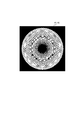
- FIG. 15 is a diagram illustrating an example of a three-dimensional image displayed by a display device mounted on a vehicle. Specifically, FIG. 15 is a diagram showing a display relating to a speedometer. By the display by the display device mounted on the vehicle, the viewer can recognize the speedometer as a stereoscopic image as shown in FIG.
- the speedometer shown in FIG. 15 is an example of display, and the display by the display device mounted on the vehicle is not limited to this.
- the display device mounted on the vehicle includes other meters related to driving of the vehicle, such as other meters such as a tachometer and a fuel meter, guidance information by a car navigation device provided in the vehicle, or an around view image based on a camera provided in the vehicle. Any information may be displayed.
- the display device described in the following embodiments can be mounted on any device other than the vehicle.
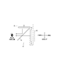
- FIG. 1 is a schematic diagram illustrating a schematic configuration of a display device 10 according to the first embodiment.
- FIG. 1A is a schematic view showing the optical system of the display device 10 according to the first embodiment in a side view.
- the display device 10 according to the first embodiment includes a single reflection mirror member 20 and a display unit 30.
- the display device 10 displays a stereoscopic image visually recognized by a viewer using an illusion phenomenon.
- the reflection mirror member 20 is, for example, a half mirror.
- the reflection mirror member 20 is not limited to this, and may be any member as long as it reflects at least part of the light incident on one surface and transmits at least part of the light incident on the other surface. It may be.
- the display unit 30 includes, for example, two liquid crystal displays.
- the display unit 30 includes a first display area 31 and a second display area 32 corresponding to each liquid crystal display.
- the first display area 31 and the second display area 32 are arranged at right angles so as to sandwich the reflection mirror member 20 when viewed from the viewing position in FIG. That is, the first display region 31 is arranged such that an axis perpendicular to the display surface and the viewer's line of sight are substantially orthogonal on the reflection mirror member 20.
- the second display region 32 is disposed on the back side of the reflection mirror member 20 so that the axis perpendicular to the display surface is substantially parallel to the line of sight of the viewer.
- the image displayed in the first display area 31 is reflected by the reflection mirror member 20.
- the viewer visually recognizes the reflected image (virtual image) of the display image.
- the reflected image is displayed on the first visual recognition area R1 (broken line in FIG. 1) that is symmetrical to the arrangement of the first display area 31 with respect to the reflection mirror member 20.
- the first visual recognition area R ⁇ b> 1 is an area that displays an image displayed in the first display area 31.
- the display image displayed in the first visual recognition area R1 is a virtual image, but is not limited thereto, and may be a real image. In the latter case, the first visual recognition area R1 and the first display area 31 coincide.
- the image displayed in the second display area 32 is transmitted through the reflection mirror member 20.
- the viewer visually recognizes the transmission image of the display image.
- the image displayed in the second display area 32 is displayed on the second visual recognition area R2 on the back side of the reflection mirror member 20 when viewed from the viewer.
- the second visual recognition area R2 is an area in which an image displayed in the second display area 32 is projected.
- the display image displayed in the second visual recognition area R2 is a real image.
- the display image displayed in the second visual recognition area R2 is not limited to this, and may be a virtual image like the display image displayed in the first visual recognition area R1.
- region R2 are spaced apart in parallel by the predetermined
- the predetermined interval in the depth direction means an arbitrary interval in the optimum range where a stereoscopic effect can be obtained.
- Each region is preferably parallel to each other along the vertical direction as shown in FIG. 1A, but is not limited thereto. Each region may not be completely parallel as long as a stereoscopic effect can be obtained.
- the first visual recognition area R1 is arranged on the near side with respect to the viewer as compared with the second visual recognition area R2. That is, as shown in FIG. 1, the first visual recognition area R ⁇ b> 1 indicated by a broken line is disposed between the reflection mirror member 20 and the second display area 32.
- FIG. 1B is a schematic diagram showing an example of an image displayed in the first display area 31 of FIG.
- FIG. 1C is a schematic diagram illustrating an example of an image displayed in the second display area 32 of FIG.
- the display unit 30 displays a two-dimensional image including information displayed on the stereoscopic image. More specifically, the display unit 30 displays an image with gradation in the first display area 31 and displays a part of the image including the gradation in the second display area 32. Thereby, the display unit 30 displays a display image with gradation in the first visual recognition area R1, and displays a part including the gradation of the display image in the second visual recognition area R2.
- the image displayed in the second display area 32 is preferably the center of the image displayed in the first display area 31. As shown in FIG. 1C, the image displayed in the second display area 32 has gradation as well as the image displayed in the first display area 31. In other words, the image displayed in the second display area 32 is obtained by extracting an area that is the central portion of the image displayed in the first display area 31 and has a gradation.
- the extracted image displayed in the second display area 32 is not limited to the central portion of the image displayed in the first display area 31, and any arbitrary image can be used as long as it has a gradation and a stereoscopic effect. May be an image in the region.
- the gradation includes a continuous change related to luminance, a continuous change related to color, or a combination thereof.
- FIGS. 1B and 1C schematically illustrate, for example, how each display image shows a continuous change in luminance.
- Each figure shows how the luminance changes by hatching.
- the display image is a circle with gradation relating to luminance, and the luminance decreases from the outer periphery toward the center. That is, the display image becomes darker from the outer periphery toward the center. In this way, the display image is an image obtained by looking into the truncated cone from the bottom surface and projecting the appearance two-dimensionally.
- Each display image has been described as a circle with a gradation related to luminance.
- the present invention is not limited to this, and any image may be used as long as it is an image with a gradation that provides a three-dimensional effect.
- the gradation pattern is not limited to the patterns as shown in FIGS. 1B and 1C, and may be any pattern as long as a stereoscopic effect can be obtained.
- the center of the display image displayed in the first visual recognition area R1 and the center of a part of the display image displayed in the second visual recognition area R2 are on one straight line perpendicular to each visual recognition area. That is, when the visual axis of the viewer perpendicular to the first visual recognition area R1 passes through the center of the display image displayed in the first visual recognition area R1, the display image displayed in the second visual recognition area R2 is displayed.
- the center exists on the extension.
- the positional relationship between the centers of the display images in each region is not limited to this, and may be any positional relationship as long as a stereoscopic effect is obtained.
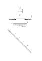
- FIG. 2 is a schematic diagram showing a stereoscopic image visually recognized by a viewer using the display device 10 of FIG.
- the viewer superimposes a part of the display image with gradation projected on the second visual recognition area R2 on the back side of the entire display image with gradation projected on the first visual recognition area R1. Visually check. At this time, gradation is given to each image, and since the change continues between the images, the viewer visually recognizes the two superimposed images as one stereoscopic image.
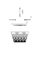
- FIG. 3 is a schematic diagram showing an outline of the principle regarding the visual recognition of the stereoscopic image of FIG.
- FIG. 4 is a conceptual diagram schematically showing the three-dimensional image of FIG. 3 visually recognized by the viewer by the optical illusion phenomenon.
- the viewer visually recognizes the two display images superimposed on each other, the viewer visually recognizes the entire stereoscopic image from the entire display image displayed in the first visual recognition area R1 on the near side.
- the viewer recognizes the stereoscopic effect of the stereoscopic image from a part of the display image displayed in the second visual recognition area R2 on the back side.
- the brightness of the display image on the near side decreases from the outer periphery toward the center.
- the brightness of the display image on the back side matches the brightness of a predetermined area of the display image on the near side, and the brightness further decreases toward the center.
- the first visual recognition area R1 and the second visual recognition area R2 are actually separated by a predetermined interval.
- the width in the vertical direction is different between the images, and the width of the image in the second visual recognition region R2 is narrow.
- the viewer tries to recognize it as a single gradation.
- the viewer visually recognizes the gradation in a separated space so as to complement the gradation, and feels the illusion as if the gradation is spreading to the back side. Therefore, as shown in FIG. 4, the viewer can create a stereoscopic image with a depth that causes the diameter of the circle to gradually decrease, for example, as the luminance continuously decreases from the near side to the far side due to the illusion phenomenon. Visually check.
- the first visual recognition area R1 and the second visual recognition area R2 are parallel to each other along the vertical direction, and predetermined in the depth direction. It is preferable that they are arranged so as to be spaced apart from each other and to be present on the visual axis of the viewer when the center of the display image of each region is viewed from the front.
- the extracted image displayed in the second visual recognition area R2 is preferably the central portion of the image displayed in the first visual recognition area R1.
- the display device 10 according to the first embodiment can more easily obtain a stereoscopic effect. That is, even if the display device 10 is used for a mortar-shaped three-dimensional decoration that looks into the truncated cone from the bottom, the viewer can visually recognize a three-dimensional image due to an illusion phenomenon.
- the display device 10 according to the first embodiment can visually recognize a stereoscopic image having a depth due to an illusion phenomenon.
- the DFD display described in Non-Patent Document 1 superimposes two entire images with different brightness on the near side and the far side.
- the display device 10 according to the first embodiment includes the entire image and a part thereof. Only superimpose. Thereby, even if a viewer's attitude
- Non-Patent Document 1 tends to impair the stereoscopic effect when the line of sight is slightly shifted.
- the display device 10 according to the first embodiment obtains the above effects.
- FIG. 5 is a schematic diagram illustrating an example of a stereoscopic image displayed by the display device 10 according to the first embodiment mounted on a vehicle.
- Fig.5 (a) is the schematic diagram which showed the mode when the speedometer which the display apparatus 10 which concerns on 1st Embodiment displays was visually recognized from the front.
- FIG. 5B is a schematic diagram showing a state when the speedometer displayed by the display device 10 according to the first embodiment is viewed from the front while changing the line of sight.
- the display device 10 displays the scale of the speedometer along the circumference of the circle displayed in the first display area 31. , Display the pointer in the center.
- the display device 10 displays a circle with gradation as shown in FIG. 1C in the second display area 32.
- a viewer that is, a driver
- superimposes on the truncated cone-shaped stereoscopic image visually recognized by the illusion phenomenon, and visually recognizes the speedometer.
- the driver can visually recognize a speedometer that floats to the near side due to an illusion phenomenon.
- the driver even if the driver changes the line of sight with the seat belt fastened, for example, the driver still uses the display device 10 according to the first embodiment mounted on the instrument panel. You can feel the feeling.
- the arrangement relationship between the first visual recognition region R1 and the second visual recognition region R2 is the same as that of the display device 10 according to the first embodiment.
- the arrangement of the first display area 31 and the second display area 32 is changed. That is, in the display device 10 according to the first to fourth embodiments, the first visual recognition area R1 is arranged on the near side with respect to the viewer as compared with the second visual recognition area R2.
- the display device 10 according to the fifth to eighth embodiments associates the arrangement of the first display region 31 and the second display region 32 with the display device 10 according to the first to fourth embodiments, respectively.
- the arrangement relationship between the first visual recognition area R1 and the second visual recognition area R2 is switched. That is, in the display device 10 according to the fifth to eighth embodiments, the first visual recognition area R1 is disposed on the back side with respect to the viewer as compared with the second visual recognition area R2.
- FIG. 6 is a schematic view showing the optical system of the display device 10 according to the second embodiment in a side view.
- the display device 10 reverses the arrangement relationship between the first display area 31 and the second display area 32.
- the second display region 32 is arranged so that the axis perpendicular to the display surface and the line of sight of the viewer are substantially orthogonal on the reflection mirror member 20.
- the first display region 31 is disposed on the back side of the reflection mirror member 20 so that the axis perpendicular to the display surface is substantially parallel to the line of sight of the viewer.
- the image displayed in the second display area 32 is reflected by the reflection mirror member 20.
- the viewer visually recognizes the reflected image of the display image in the second visual recognition area R2.
- the second display area 32 is installed at a position symmetrical to the second visual recognition area R ⁇ b> 2 with respect to the reflection mirror member 20.
- the display image displayed in the second visual recognition area R2 is a virtual image.
- the image displayed in the first display area 31 is transmitted through the reflection mirror member 20.
- the viewer visually recognizes the transmission image of the display image.
- the image displayed in the first display area 31 is displayed on the first visual recognition area R1 on the back side of the reflection mirror member 20 when viewed from the viewer.
- the display image displayed in the first visual recognition area R1 is a real image.
- the display device 10 according to the second embodiment can visually recognize a stereoscopic image similar to that in FIG. That is, the display device 10 according to the second embodiment has the same effect as that of the first embodiment.
- FIG. 7 is a schematic view showing the optical system of the display device 10 according to the third embodiment in a side view.
- the display device 10 aligns the arrangement relationship between the first display area 31 and the second display area 32 on the same surface side of the reflection mirror member 20. That is, the first display area 31 and the second display area 32 are arranged such that the axis perpendicular to each display surface and the line of sight of the viewer are substantially orthogonal on the reflection mirror member 20.
- the first display area 31 is disposed on the front side of the second display area 32 with respect to the reflection surface of the reflection mirror member 20. That is, the first display area 31 is disposed between the second display area 32 and the reflection mirror member 20.
- the images displayed in the first display area 31 and the second display area 32 are reflected by the reflection mirror member 20.
- the viewer visually recognizes the reflected images of the two display images in the first visual recognition area R1 and the second visual recognition area R2.
- the first display area 31 and the second display area 32 are installed at positions symmetrical to the first visual recognition area R1 and the second visual recognition area R2 with respect to the reflection mirror member 20, respectively.
- the display images displayed in the first visual recognition area R1 and the second visual recognition area R2 are both virtual images.
- the first display region 31 in order to transmit the light from the second display region 32, the first display region 31 needs to adopt a transparent liquid crystal display, for example.
- the first display area 31 is an arbitrary display having arbitrary transparency as long as a display image can be displayed in each of the first visual recognition area R1 and the second visual recognition area R2 so that a stereoscopic effect can be obtained. Good.
- the display device 10 according to the third embodiment can visually recognize a stereoscopic image similar to that in FIG. That is, the display device 10 according to the third embodiment has the same effect as that of the first embodiment.
- FIG. 8 is a schematic view showing the optical system of the display device 10 according to the fourth embodiment in a side view.
- the display device 10 does not have the reflection mirror member 20.
- the first display area 31 and the second display area 32 overlap each other so that the axis perpendicular to each display surface is substantially parallel to the line of sight of the viewer.
- the first display area 31 is arranged closer to the viewer than the second display area 32. That is, the first display area 31 is disposed between the second display area 32 and the viewer.
- the viewer visually recognizes the image displayed in the first display area 31 directly.
- the first display area 31 transmits the image displayed in the second display area 32.
- the viewer visually recognizes the transmission image of the display image.
- the 1st display area 31 needs to be comprised by a transparent liquid crystal display like 3rd Embodiment, for example.
- the first visual recognition area R1 and the second visual recognition area R2 coincide with the first display area 31 and the second display area 32, respectively. Therefore, the display image displayed in each viewing area is a real image.
- the display device 10 according to the fourth embodiment can visually recognize a stereoscopic image similar to that in FIG. That is, the display device 10 according to the fourth embodiment has the same effect as that of the first embodiment.
- the display device 10 according to the fourth embodiment does not include the reflection mirror member 20, the entire device can be reduced in size.
- FIG. 9 is a schematic view showing the optical system of the display device 10 according to the fifth embodiment in a side view.
- FIG. 10 is a schematic diagram showing an outline of the principle regarding the visual recognition of the stereoscopic image of FIG. In FIG. 10, only the reflection mirror member 20, the first visual recognition area R1, the second visual recognition area R2, and the second display area 32 are illustrated.
- FIG. 11 is a conceptual diagram schematically showing the three-dimensional image of FIG. 10 visually recognized by the viewer by the optical illusion phenomenon.
- the display device 10 interchanges the arrangement relationship between the first visual recognition region R1 and the second visual recognition region R2 as compared with the first embodiment. That is, the second visual recognition area R2 is disposed between the first visual recognition area R1 and the reflection mirror member 20. On the other hand, the first display area 31 is arranged at a position symmetrical to the first visual recognition area R1 with respect to the reflection mirror member 20. The second display area 32 coincides with the second visual recognition area R2.
- the viewer visually recognizes the two display images superimposed on each other, the viewer visually recognizes the entire view of the three-dimensional image from the entire display image displayed in the first visual recognition area R1 on the back side.
- the viewer recognizes the stereoscopic effect of the stereoscopic image based on a part of the display image displayed in the second visual recognition area R2 on the near side.
- the brightness of the display image on the far side decreases as it goes from the outer periphery toward the center.
- the brightness of the display image on the near side coincides with the brightness of a predetermined area of the display image on the far side, and the brightness further decreases toward the center. Similar to the principle described with reference to FIG.
- the viewer visually recognizes the gradation to complement the gradation in a separated space, and feels the illusion as if the gradation is raised to the near side. Therefore, as shown in FIG. 11, the viewer sees a stereoscopic image that protrudes toward the front side, for example, the brightness continuously decreases from the back side toward the front side, and the diameter of the circle gradually narrows. Is visually recognized.
- the display device 10 displays the scale of the speedometer along the circumference of the circle displayed in the second display area 32. , Display the pointer in the center.
- the display device 10 displays a circle with gradation as shown in FIG. 1B in the first display area 31.
- a viewer that is, a driver
- superimposes on the truncated cone-shaped stereoscopic image visually recognized by the illusion phenomenon, and visually recognizes the speedometer.
- the driver can visually recognize a speedometer that floats to the near side due to an illusion phenomenon.
- the display device 10 according to the fifth embodiment has the same effects as those of the first embodiment.
- the display device 10 according to the fifth embodiment can visually recognize a three-dimensional image that protrudes to the near side due to an illusion phenomenon.
- FIG. 12 is a schematic view showing the optical system of the display device 10 according to the sixth embodiment in a side view.
- the display device 10 reverses the arrangement relationship between the first display area 31 and the second display area 32 from that of the fifth embodiment.
- the second display region 32 is arranged so that the axis perpendicular to the display surface and the line of sight of the viewer are substantially orthogonal on the reflection mirror member 20.
- the first display region 31 is disposed on the back side of the reflection mirror member 20 so that the axis perpendicular to the display surface is substantially parallel to the line of sight of the viewer.
- the second display area 32 is installed at a position symmetrical to the second visual recognition area R2 with respect to the reflection mirror member 20.
- the first display area 31 coincides with the first visual recognition area R1.
- the display image displayed in the second visual recognition area R2 is a virtual image
- the display image displayed in the first visual recognition area R1 is a real image.
- the display device 10 according to the sixth embodiment can visually recognize a stereoscopic image similar to that in FIG. 11 due to the illusion phenomenon. That is, the display device 10 according to the sixth embodiment has the same effect as that of the fifth embodiment.
- FIG. 13 is a schematic view showing the optical system of the display device 10 according to the seventh embodiment in a side view.
- the display device 10 according to the seventh embodiment has the same configuration as that of the third embodiment, but is different in that the arrangement relationship between the first display area 31 and the second display area 32 is switched.
- the first display area 31 and the second display area 32 are arranged at positions symmetrical to the first visual recognition area R1 and the second visual recognition area R2 with respect to the reflection mirror member 20, respectively.
- the second display region 32 in order to transmit light from the first display region 31, the second display region 32 needs to adopt a transparent liquid crystal display, for example.
- the second display area 32 is an arbitrary display having arbitrary transparency as long as a display image can be displayed in each of the first visual recognition area R1 and the second visual recognition area R2 so that a stereoscopic effect can be obtained. Good.
- the display device 10 according to the seventh embodiment can visually recognize a stereoscopic image similar to that in FIG. That is, the display device 10 according to the seventh embodiment has the same effect as that of the fifth embodiment.
- FIG. 14 is a schematic view showing the optical system of the display device 10 according to the eighth embodiment in a side view.
- the display device 10 according to the eighth embodiment has the same configuration as that of the fourth embodiment, but is different in that the arrangement relationship between the first display area 31 and the second display area 32 is switched.
- the first display area 31 is disposed on the far side of the second display area 32 with respect to the viewer.
- the second display area 32 transmits the image displayed in the first display area 31.
- the viewer visually recognizes the transmission image of the display image.
- the second display area 32 needs to be configured by a transparent liquid crystal display, for example.
- the display device 10 according to the eighth embodiment can visually recognize a stereoscopic image similar to that in FIG. 11 due to the illusion phenomenon. That is, the display device 10 according to the eighth embodiment has the same effect as that of the fifth embodiment. In addition, since the display device 10 according to the eighth embodiment does not include the reflection mirror member 20, the entire device can be reduced in size.
Landscapes
- Engineering & Computer Science (AREA)
- Chemical & Material Sciences (AREA)
- Mechanical Engineering (AREA)
- Transportation (AREA)
- Combustion & Propulsion (AREA)
- General Physics & Mathematics (AREA)
- Theoretical Computer Science (AREA)
- Physics & Mathematics (AREA)
- Multimedia (AREA)
- Signal Processing (AREA)
- Computer Hardware Design (AREA)
- Devices For Indicating Variable Information By Combining Individual Elements (AREA)
- Instrument Panels (AREA)
- Testing, Inspecting, Measuring Of Stereoscopic Televisions And Televisions (AREA)
Abstract
より立体感を得やすい表示装置を提供する。 視認者に立体的画像を視認させる、本発明に係る表示装置(10)は、視認者の視線上で、奥行き方向に所定の間隔で離間して略平行に重畳する、第1の視認領域(R1)と第2の視認領域(R2)と、を有し、立体的画像に表示される情報を含む二次元の画像を表示する表示部(30)を備え、表示部(30)は、第1の視認領域(R1)に、グラデーションを付した表示画像を映し出し、第2の視認領域(R2)に、当該表示画像のグラデーションを含んだ一部を映し出す。
Description
本出願は、2016年5月13日に日本国に特許出願された特願2016-097308の優先権を主張するものであり、これら先の出願の開示全体をここに参照のために取り込む。
本発明は、三次元の画像として視認される視認画像を表示する表示装置に関する。
従来、2つの表示部とハーフミラーとを使用して立体的二次元画像を表示する表示装置が知られている。例えば、特許文献1には、第1表示部に表示された二次元画像と、第2表示部に表示された二次元画像をハーフミラーで反射させた二次元画像とにより、立体的二次元画像を表示する立体的二次元画像表示装置が開示されている。
従来、錯視現象を利用した立体的画像の表示方法が知られている。例えば、非特許文献1には、輝度を変化させた2つの画像を前後2面に重ね合わせて立体的画像を表示するDFD(Depth-Fused 3D)ディスプレイが開示されている。
▲高▼田英明、陶山史朗、伊達宗和、中沢憲二、"前後2面のLCDを積層したDFDディスプレイ"、[online]、2005年2月、NTT技術ジャーナル 2005.2、[平成28年4月20日検索]、インターネット<URL:http://www.ntt.co.jp/journal/0502/files/jn200502021.pdf>
しかしながら、例えば、円錐台を底面から覗き込んだようなすり鉢形状の立体的加飾に上記の従来の装置及びディスプレイを採用すると、中央に向かって陰影がつくために、立体感を得にくいという問題があった。
かかる観点に鑑みてなされた本発明の目的は、より立体感を得やすい表示装置を提供することにある。
上記課題を解決するために、本発明の一実施形態に係る表示装置は、
視認者に立体的画像を視認させる表示装置であって、
前記視認者の視線上で、奥行き方向に所定の間隔で離間して略平行に重畳する、第1の視認領域と第2の視認領域と、を有し、
前記立体的画像に表示される情報を含む二次元の画像を表示する表示部を備え、
前記表示部は、前記第1の視認領域に、グラデーションを付した表示画像を映し出し、前記第2の視認領域に、当該表示画像のグラデーションを含んだ一部を映し出す。
視認者に立体的画像を視認させる表示装置であって、
前記視認者の視線上で、奥行き方向に所定の間隔で離間して略平行に重畳する、第1の視認領域と第2の視認領域と、を有し、
前記立体的画像に表示される情報を含む二次元の画像を表示する表示部を備え、
前記表示部は、前記第1の視認領域に、グラデーションを付した表示画像を映し出し、前記第2の視認領域に、当該表示画像のグラデーションを含んだ一部を映し出す。
本発明の一実施形態に係る表示装置によれば、より立体感を得やすい。
以下の実施形態において説明する表示装置は、多様な機器に搭載して使用することができる。以下の実施形態において説明する表示装置は、例えば、車両のインストルメントパネルに搭載できる。車両に搭載された表示装置は、車両の運転に関連する多様な情報を表示する。
表示装置を車両に搭載する場合、表示装置の視認位置は運転席であることが好ましい。これにより、視認者は運転席から車両の運転に関する情報を立体的画像として視認できる。従って、視認者は、運転中に、表示装置による表示を確認しやすくなる。
図15は、車両に搭載された表示装置が表示する立体的画像の一例を示す図である。具体的には、図15は、速度計に関する表示を示す図である。車両に搭載された表示装置による表示により、視認者は、図15に示すように速度計を立体的画像として認識できる。
図15に示す速度計は表示の一例であり、車両に搭載された表示装置による表示は、これに限定されない。車両に搭載された表示装置は、例えば、タコメータ及び燃料計等の他のメータ、車両が備えるカーナビゲーション装置による案内情報、又は車両が備えるカメラに基づくアラウンドビュー画像等、車両の運転に関連する他の任意の情報を表示してもよい。
以下の実施形態において説明する表示装置は、車両以外の他の任意の機器にも搭載できる。
以降、諸図面を参照しながら、本発明の実施形態について詳細に説明する。
(第1実施形態)
図1は、第1実施形態に係る表示装置10の概略構成を示す模式図である。図1(a)は、第1実施形態に係る表示装置10の光学系を側面視により示した模式図である。図1(a)に示すように、第1実施形態に係る表示装置10は、1枚の反射ミラー部材20と、表示部30と、を備える。表示装置10は、錯視現象を利用して、視認者により視認される立体的画像を表示する。
図1は、第1実施形態に係る表示装置10の概略構成を示す模式図である。図1(a)は、第1実施形態に係る表示装置10の光学系を側面視により示した模式図である。図1(a)に示すように、第1実施形態に係る表示装置10は、1枚の反射ミラー部材20と、表示部30と、を備える。表示装置10は、錯視現象を利用して、視認者により視認される立体的画像を表示する。
反射ミラー部材20は、例えば、ハーフミラーである。反射ミラー部材20は、これに限定されず、一方の表面に入射した光の少なくとも一部を反射し、他方の表面に入射した光の少なくとも一部を透過する部材であれば、任意の部材であってよい。
表示部30は、例えば、2枚の液晶ディスプレイにより構成される。表示部30は、各液晶ディスプレイに対応する、第1の表示領域31及び第2の表示領域32を有する。第1の表示領域31及び第2の表示領域32は、図1の視認位置から見て、反射ミラー部材20を挟むように、直角に配置される。すなわち、第1の表示領域31は、表示面に垂直な軸と視認者の視線とが反射ミラー部材20上で略直交するように配置される。一方で、第2の表示領域32は、表示面に垂直な軸が視認者の視線と略平行になるように、反射ミラー部材20の奥側に配置される。
第1の表示領域31に表示される画像は、反射ミラー部材20によって反射される。視認者は、表示画像の反射像(虚像)を視認する。当該反射像は、反射ミラー部材20に対して第1の表示領域31の配置と対称的な位置にある第1の視認領域R1(図1の破線)上に映し出される。第1の視認領域R1とは、第1の表示領域31に表示される画像を映し出す領域である。本実施形態では、第1の視認領域R1に映し出される表示画像は、虚像であるが、これに限定されず、実像であってもよい。後者の場合、第1の視認領域R1と第1の表示領域31とは、一致する。
第2の表示領域32に表示される画像は、反射ミラー部材20を透過する。視認者は、表示画像の透過像を視認する。第2の表示領域32に表示される画像は、視認者から見て反射ミラー部材20の奥側にある第2の視認領域R2上に映し出される。第2の視認領域R2とは、第2の表示領域32に表示される画像を映し出す領域である。本実施形態では、第2の視認領域R2と第2の表示領域32とが一致するので、第2の視認領域R2に映し出される表示画像は、実像である。第2の視認領域R2に映し出される表示画像は、これに限定されず、第1の視認領域R1に映し出される表示画像のように、虚像であってもよい。
第1の視認領域R1と第2の視認領域R2とは、視認者の視線上で、奥行き方向に所定の間隔で離間して平行に重畳する。奥行き方向の所定の間隔とは、立体感が得られる最適範囲の任意の間隔を意味する。各領域は、図1(a)のように、鉛直方向に沿って互いに平行であるのが好適であるが、これに限定されない。各領域は、立体感が得られるのであれば、完全に平行でなくてもよい。
本実施形態では、第1の視認領域R1は、第2の視認領域R2と比較して、視認者に対して手前側に配置される。すなわち、図1に示すとおり、破線により示した第1の視認領域R1は、反射ミラー部材20と第2の表示領域32との間に配置される。
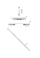
図1(b)は、図1の第1の表示領域31に表示される画像の一例を示す模式図である。図1(c)は、図1の第2の表示領域32に表示される画像の一例を示す模式図である。
表示部30は、立体的画像に表示される情報を含む二次元の画像を表示する。より具体的には、表示部30は、第1の表示領域31に、グラデーションを付した画像を表示し、第2の表示領域32に、当該画像のグラデーションを含んだ一部を表示する。これにより、表示部30は、第1の視認領域R1に、グラデーションを付した表示画像を映し出し、第2の視認領域R2に、当該表示画像のグラデーションを含んだ一部を映し出す。
第2の表示領域32に表示される画像は、第1の表示領域31に表示される画像の中心部であるのが好適である。図1(c)に示すように、第2の表示領域32に表示される画像も、第1の表示領域31に表示される画像と同様に、グラデーションを有する。すなわち、第2の表示領域32に表示される画像は、第1の表示領域31に表示される画像の中心部であって、かつ、グラデーションが付されている領域を抽出したものである。
第2の表示領域32に表示される抽出画像は、第1の表示領域31に表示される画像の中心部に限定されず、グラデーションが付されており立体感が得られる領域であれば、任意の領域における画像であってよい。
グラデーションは、輝度に関する連続的変化、色彩に関する連続的変化、又はこれらの組合せを含む。図1(b)及び(c)は、例えば、各表示画像が輝度に関する連続的変化を示す様子を模式的に描いている。各図は、輝度の変化の様子を、ハッチングの濃淡により示す。各図では、表示画像は、輝度に関するグラデーションが付された円であり、外周から中心に向かうに従って、輝度が低下する。すなわち、表示画像は、外周から中心に向かうほど、暗くなる。このように、表示画像は、円錐台を底面から覗き込み、その様子を二次元に投影したような画像となっている。
各表示画像は、輝度に関するグラデーションが付された円であるとして説明したが、これに限定されず、立体感が得られるグラデーション付きの画像であれば、任意の画像であってよい。グラデーションのパターンも、図1(b)及び(c)のようなパターンに限定されず、立体感が得られるパターンであれば、任意のパターンであってよい。
第1の視認領域R1に映し出された表示画像の中心と、第2の視認領域R2に映し出された表示画像の一部の中心とは、各視認領域に垂直な1つの直線上にある。すなわち、第1の視認領域R1に垂直な視認者の視線軸が、第1の視認領域R1に映し出された表示画像の中心を通過するとき、第2の視認領域R2に映し出された表示画像の中心は、その延長上に存在する。各領域の表示画像の中心の位置関係は、これに限定されず、立体感が得られる位置関係であれば、任意の位置関係であってよい。
図2は、図1の表示装置10により視認者が視認する立体的画像を示した模式図である。
視認者は、第1の視認領域R1に映し出された、グラデーション付きの表示画像全体の奥側に、第2の視認領域R2に映し出された、グラデーション付きの当該表示画像の一部を重畳させて視認する。この時、各画像にグラデーションが付されており、各画像の間で変化が連続するので、視認者は、重畳された2つの画像を1つの立体的画像として視認する。
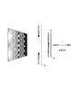
以下では、視認者が上記の重畳された2つのグラデーション画像を1つの立体的画像として視認する原理の概要を、図3及び図4を用いて説明する。図3は、図2の立体的画像の視認に関する原理の概要を示した模式図である。図3では、反射ミラー部材20、第1の視認領域R1、第2の視認領域R2、及び第2の表示領域32のみを図示している。図4は、視認者が錯視現象により視認する図3の立体的画像を模式的に示した概念図である。
視認者は、2つの表示画像を重畳して視認する時、立体的画像の全貌を手前側にある第1の視認領域R1に映し出された表示画像全体により視認する。一方で、視認者は、立体的画像の立体感を奥側にある第2の視認領域R2に映し出された表示画像の一部により認識する。上述したとおり、手前側にある表示画像は、外周から中心に向かうほど輝度が低下する。同様に、奥側にある表示画像は、その外周の輝度が手前側の表示画像の所定の領域の輝度と一致し、中心に向かうほどさらに輝度が低下する。視認者は、2つの表示画像を重畳して視認する時、各画像のグラデーションをまとめて1つのグラデーションとして認識する。この時、図3に示すとおり、実際には、第1の視認領域R1と第2の視認領域R2とは所定の間隔により離間している。図3に示すように、各画像の間で鉛直方向の幅は異なっており、第2の視認領域R2にある画像の幅が狭い。実際の配置及び幅にはこのような差異があるにも関わらず、視認者は、1つのまとまったグラデーションとして認識しようとする。これにより、視認者は、離間している空間上で、グラデーションを補完するように視認し、あたかもグラデーションが奥側に広がっているかのような錯覚を覚える。従って、視認者は、図4に示すとおり、手前側から奥側に向かって、例えば輝度が連続的に低下し、徐々に円の直径が狭まるような、奥行きのある立体的画像を錯視現象により視認する。
上記のような原理によると、視認者が立体感を最も感じるためには、第1の視認領域R1及び第2の視認領域R2は、鉛直方向に沿って互いに平行であり、奥行き方向に所定の間隔で互いに離間し、かつ、各領域の表示画像の中心が正面から視認した時の視認者の視線軸上に存在するように配置されるのが好適である。第2の視認領域R2に映し出される抽出画像は、第1の視認領域R1に映し出される画像の中心部であるのが好適である。
以上により、第1実施形態に係る表示装置10は、より立体感を得やすい。すなわち、円錐台を底面から覗き込んだようなすり鉢形状の立体的加飾に表示装置10を採用したとしても、視認者は、錯視現象により、立体的画像を視認できる。第1実施形態に係る表示装置10は、錯視現象により、奥行きのある立体的画像を視認させることができる。
非特許文献1に記載のDFDディスプレイは、手前側と奥側で、輝度を変えた2つの画像全体を重畳させているが、第1実施形態に係る表示装置10は、画像全体とその一部のみを重畳させている。これにより、視認者の姿勢が崩れて、視線が少しずれたとしても、第1実施形態に係る表示装置10は、立体感を維持できる。すなわち、全体の画像同士を重畳させた状態で視線がずれると、視認者が視認する、各画像に表示された各同一要素間の空間的なずれは、広範囲にわたる。従って、非特許文献1に記載のDFDディスプレイは、視線が少しずれると、立体感を損いやすい。一方で、全体画像にその一部を重畳させた状態では、視線がずれたとしても、空間的なずれに関する範囲は狭まる。従って、第1実施形態に係る表示装置10は、上記の効果を得る。
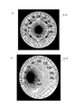
図5は、車両に搭載された第1実施形態に係る表示装置10が表示する立体的画像の一例を示した模式図である。図5(a)は、第1実施形態に係る表示装置10が表示する速度計を正面から視認した時の様子を示した模式図である。図5(b)は、第1実施形態に係る表示装置10が表示する速度計を正面から視線を変えて視認した時の様子を示した模式図である。
第1実施形態に係る表示装置10が表示する立体的画像が速度計である場合、表示装置10は、第1の表示領域31に表示された円の外周に沿って速度計の目盛りを表示し、その中心部に指針を表示する。表示装置10は、第2の表示領域32に、図1(c)のようなグラデーション付きの円を表示する。これにより、視認者、すなわち運転者は、錯視現象により視認される円錐台形状の立体的画像に重畳して、上記の速度計を視認する。この時、運転者は、図15に示すとおり、錯視現象により手前側に浮き出るような速度計を視認できる。
図5(b)に示すとおり、運転者は、例えばシートベルトを締めた状態で視線を変える場合であっても、インストルメントパネルに搭載された第1実施形態に係る表示装置10により、依然として立体感を感じることができる。
以下の第2乃至第4実施形態に係る表示装置10は、第1の視認領域R1及び第2の視認領域R2の配置関係を第1実施形態に係る表示装置10と同様にした状態で、第1の表示領域31及び第2の表示領域32の配置を変更する。すなわち、第1乃至第4実施形態に係る表示装置10では、第1の視認領域R1は、第2の視認領域R2と比較して、視認者に対して手前側に配置される。
一方で、第5乃至第8実施形態に係る表示装置10は、第1の表示領域31及び第2の表示領域32の配置を、それぞれ第1乃至第4実施形態に係る表示装置10と対応させながら、第1の視認領域R1及び第2の視認領域R2の配置関係を入れ替える。すなわち、第5乃至第8実施形態に係る表示装置10では、第1の視認領域R1は、第2の視認領域R2と比較して、視認者に対して奥側に配置される。
以下では、第1実施形態と同じ構成部については同一の符号を付す。その説明を省略し、第1実施形態と異なる点について主に説明する。第1実施形態で説明した各バリエーションは、第2乃至第8実施形態に係る表示装置10に対してもそのまま適用される。
(第2実施形態)
図6は、第2実施形態に係る表示装置10の光学系を側面視により示した模式図である。
図6は、第2実施形態に係る表示装置10の光学系を側面視により示した模式図である。
第2実施形態に係る表示装置10は、第1の表示領域31及び第2の表示領域32の配置関係を逆にする。すなわち、第2の表示領域32は、表示面に垂直な軸と視認者の視線とが反射ミラー部材20上で略直交するように配置される。一方で、第1の表示領域31は、表示面に垂直な軸が視認者の視線と略平行になるように、反射ミラー部材20の奥側に配置される。
第2の表示領域32に表示される画像は、反射ミラー部材20によって反射される。視認者は、表示画像の反射像を第2の視認領域R2で視認する。換言すると、第2の表示領域32は、反射ミラー部材20に対して第2の視認領域R2と対称的な位置に設置される。本実施形態では、第2の視認領域R2に映し出される表示画像は、虚像である。
第1の表示領域31に表示される画像は、反射ミラー部材20を透過する。視認者は、表示画像の透過像を視認する。第1の表示領域31に表示される画像は、視認者から見て反射ミラー部材20の奥側にある第1の視認領域R1上に映し出される。本実施形態では、第1の視認領域R1と第1の表示領域31とが一致するので、第1の視認領域R1に映し出される表示画像は、実像である。
以上のような配置によっても、第2実施形態に係る表示装置10は、錯視現象により図2と同様の立体的画像を視認させることができる。すなわち、第2実施形態に係る表示装置10は、第1実施形態と同様の効果を奏する。
(第3実施形態)
図7は、第3実施形態に係る表示装置10の光学系を側面視により示した模式図である。
図7は、第3実施形態に係る表示装置10の光学系を側面視により示した模式図である。
第3実施形態に係る表示装置10は、第1の表示領域31及び第2の表示領域32の配置関係を、反射ミラー部材20の同一面側に揃える。すなわち、第1の表示領域31及び第2の表示領域32は、各表示面に垂直な軸と視認者の視線とが反射ミラー部材20上で略直交するように配置される。第1の表示領域31は、反射ミラー部材20の反射面に対して、第2の表示領域32よりも手前側に配置される。すなわち、第1の表示領域31は、第2の表示領域32と反射ミラー部材20との間に配置される。
第1の表示領域31及び第2の表示領域32に表示される画像は、反射ミラー部材20によって反射される。視認者は、2つの表示画像の反射像を、第1の視認領域R1及び第2の視認領域R2でそれぞれ視認する。換言すると、第1の表示領域31及び第2の表示領域32は、反射ミラー部材20に対して、第1の視認領域R1及び第2の視認領域R2と対称的な位置にそれぞれ設置される。本実施形態では、第1の視認領域R1及び第2の視認領域R2に映し出される表示画像は、共に虚像である。
第3実施形態に係る表示装置10では、第2の表示領域32からの光を透過するために、第1の表示領域31は、例えば、透明な液晶ディスプレイを採用する必要がある。第1の表示領域31は、立体感が得られるように第1の視認領域R1及び第2の視認領域R2に表示画像をそれぞれ映し出すことができれば、任意の透明度を有する、任意のディスプレイであってよい。
以上のような配置によっても、第3実施形態に係る表示装置10は、錯視現象により図2と同様の立体的画像を視認させることができる。すなわち、第3実施形態に係る表示装置10は、第1実施形態と同様の効果を奏する。
(第4実施形態)
図8は、第4実施形態に係る表示装置10の光学系を側面視により示した模式図である。
図8は、第4実施形態に係る表示装置10の光学系を側面視により示した模式図である。
第4実施形態に係る表示装置10は、反射ミラー部材20を有さない。第1の表示領域31と第2の表示領域32とは、各表示面に垂直な軸が視認者の視線と略平行になるように、互いに重畳する。第1の表示領域31は、視認者に対して、第2の表示領域32よりも手前側に配置される。すなわち、第1の表示領域31は、第2の表示領域32と視認者との間に配置される。
視認者は、第1の表示領域31に表示される画像を、直接視認する。一方で、第1の表示領域31は、第2の表示領域32に表示される画像を透過する。視認者は、表示画像の透過像を視認する。ここで、第1の表示領域31は、第3実施形態同様に、例えば、透明な液晶ディスプレイにより構成される必要がある。
本実施形態では、第1の視認領域R1及び第2の視認領域R2は、第1の表示領域31及び第2の表示領域32とそれぞれ一致する。従って、各視認領域に映し出される表示画像は、実像である。
以上のような配置によっても、第4実施形態に係る表示装置10は、錯視現象により図2と同様の立体的画像を視認させることができる。すなわち、第4実施形態に係る表示装置10は、第1実施形態と同様の効果を奏する。加えて、第4実施形態に係る表示装置10は、反射ミラー部材20を有さないので、装置全体の小型化を可能にする。
(第5実施形態)
図9は、第5実施形態に係る表示装置10の光学系を側面視により示した模式図である。図10は、図9の立体的画像の視認に関する原理の概要を示した模式図である。図10では、反射ミラー部材20、第1の視認領域R1、第2の視認領域R2、及び第2の表示領域32のみを図示している。図11は、視認者が錯視現象により視認する図10の立体的画像を模式的に示した概念図である。
図9は、第5実施形態に係る表示装置10の光学系を側面視により示した模式図である。図10は、図9の立体的画像の視認に関する原理の概要を示した模式図である。図10では、反射ミラー部材20、第1の視認領域R1、第2の視認領域R2、及び第2の表示領域32のみを図示している。図11は、視認者が錯視現象により視認する図10の立体的画像を模式的に示した概念図である。
第5実施形態に係る表示装置10は、第1実施形態と比較して、第1の視認領域R1及び第2の視認領域R2の配置関係を入れ替える。すなわち、第2の視認領域R2は、第1の視認領域R1と反射ミラー部材20との間に配置される。一方で、第1の表示領域31は、反射ミラー部材20に対して第1の視認領域R1と対称的な位置に配置される。第2の表示領域32は、第2の視認領域R2と一致する。
視認者は、2つの表示画像を重畳して視認する時、立体的画像の全貌を奥側にある第1の視認領域R1に映し出された表示画像全体により視認する。一方で、視認者は、立体的画像の立体感を手前側にある第2の視認領域R2に映し出された表示画像の一部により認識する。上述したとおり、奥側にある表示画像は、外周から中心に向かうほど輝度が低下する。同様に、手前側にある表示画像は、その外周の輝度が奥側の表示画像の所定の領域の輝度と一致し、中心に向かうほどさらに輝度が低下する。図3を用いて説明した原理と同様に、視認者は、離間している空間上で、グラデーションを補完するように視認し、あたかもグラデーションが手前側に浮き出しているかのような錯覚を覚える。従って、視認者は、図11に示すとおり、奥側から手前側に向かって、例えば輝度が連続的に低下し、徐々に円の直径が狭まるような、手前側に浮き出る立体的画像を錯視現象により視認する。
第5実施形態に係る表示装置10が表示する立体的画像が速度計である場合、表示装置10は、第2の表示領域32に表示された円の外周に沿って速度計の目盛りを表示し、その中心部に指針を表示する。表示装置10は、第1の表示領域31に、図1(b)のようなグラデーション付きの円を表示する。これにより、視認者、すなわち運転者は、錯視現象により視認される円錐台形状の立体的画像に重畳して、上記の速度計を視認する。この時、運転者は、図15に示すとおり、錯視現象により手前側に浮き出るような速度計を視認できる。
以上により、第5実施形態に係る表示装置10は、原則的に、第1実施形態と同様の効果を奏する。一方で、第5実施形態に係る表示装置10は、第1実施形態と異なり、錯視現象により、手前側に浮き出る立体的画像を視認させることができる。
(第6実施形態)
図12は、第6実施形態に係る表示装置10の光学系を側面視により示した模式図である。
図12は、第6実施形態に係る表示装置10の光学系を側面視により示した模式図である。
第6実施形態に係る表示装置10は、第1の表示領域31及び第2の表示領域32の配置関係を、第5実施形態と逆にする。すなわち、第2の表示領域32は、表示面に垂直な軸と視認者の視線とが反射ミラー部材20上で略直交するように配置される。一方で、第1の表示領域31は、表示面に垂直な軸が視認者の視線と略平行になるように、反射ミラー部材20の奥側に配置される。
第2の表示領域32は、反射ミラー部材20に対して第2の視認領域R2と対称的な位置に設置される。第1の表示領域31は、第1の視認領域R1と一致する。本実施形態では、第2の視認領域R2に映し出される表示画像は、虚像であり、第1の視認領域R1に映し出される表示画像は、実像である。
以上のような配置によっても、第6実施形態に係る表示装置10は、錯視現象により図11と同様の立体的画像を視認させることができる。すなわち、第6実施形態に係る表示装置10は、第5実施形態と同様の効果を奏する。
(第7実施形態)
図13は、第7実施形態に係る表示装置10の光学系を側面視により示した模式図である。
図13は、第7実施形態に係る表示装置10の光学系を側面視により示した模式図である。
第7実施形態に係る表示装置10は、第3実施形態と同様の構成であるが、第1の表示領域31及び第2の表示領域32の配置関係が入れ替わっている点で相違する。第1の表示領域31及び第2の表示領域32は、反射ミラー部材20に対して、第1の視認領域R1及び第2の視認領域R2と対称的な位置にそれぞれ配置される。
第7実施形態に係る表示装置10では、第1の表示領域31からの光を透過するために、第2の表示領域32は、例えば、透明な液晶ディスプレイを採用する必要がある。第2の表示領域32は、立体感が得られるように第1の視認領域R1及び第2の視認領域R2に表示画像をそれぞれ映し出すことができれば、任意の透明度を有する、任意のディスプレイであってよい。
以上のような配置によっても、第7実施形態に係る表示装置10は、錯視現象により図11と同様の立体的画像を視認させることができる。すなわち、第7実施形態に係る表示装置10は、第5実施形態と同様の効果を奏する。
(第8実施形態)
図14は、第8実施形態に係る表示装置10の光学系を側面視により示した模式図である。
図14は、第8実施形態に係る表示装置10の光学系を側面視により示した模式図である。
第8実施形態に係る表示装置10は、第4実施形態と同様の構成であるが、第1の表示領域31及び第2の表示領域32の配置関係が入れ替わっている点で相違する。すなわち、第1の表示領域31は、視認者に対して、第2の表示領域32よりも奥側に配置される。
視認者は、第2の表示領域32に表示される画像を、直接視認する。一方で、第2の表示領域32は、第1の表示領域31に表示される画像を透過する。視認者は、表示画像の透過像を視認する。第2の表示領域32は、第7実施形態同様に、例えば、透明な液晶ディスプレイにより構成される必要がある。
以上のような配置によっても、第8実施形態に係る表示装置10は、錯視現象により図11と同様の立体的画像を視認させることができる。すなわち、第8実施形態に係る表示装置10は、第5実施形態と同様の効果を奏する。加えて、第8実施形態に係る表示装置10は、反射ミラー部材20を有さないので、装置全体の小型化を可能にする。
本発明は、その精神又はその本質的な特徴から離れることなく、上述した実施形態以外の他の所定の形態で実現できることは当業者にとって明白である。従って、先の記述は例示的なものであり、これに限定されるものではない。発明の範囲は、先の記述によってではなく、付加した請求項によって定義される。あらゆる変更のうちその均等の範囲内にあるいくつかの変更は、その中に包含されるものとする。
10 表示装置
20 反射ミラー部材
30 表示部
31 第1の表示領域
32 第2の表示領域
R1 第1の視認領域
R2 第2の視認領域
20 反射ミラー部材
30 表示部
31 第1の表示領域
32 第2の表示領域
R1 第1の視認領域
R2 第2の視認領域
Claims (8)
- 視認者に立体的画像を視認させる表示装置であって、
前記視認者の視線上で、奥行き方向に所定の間隔で離間して略平行に重畳する、第1の視認領域と第2の視認領域と、を有し、
前記立体的画像に表示される情報を含む二次元の画像を表示する表示部を備え、
前記表示部は、前記第1の視認領域に、グラデーションを付した表示画像を映し出し、前記第2の視認領域に、当該表示画像のグラデーションを含んだ一部を映し出す、
表示装置。 - 前記第1の視認領域は、前記第2の視認領域と比較して、前記視認者に対して手前側に配置される、
請求項1に記載の表示装置。 - 前記第1の視認領域は、前記第2の視認領域と比較して、前記視認者に対して奥側に配置される、
請求項1に記載の表示装置。 - 反射ミラー部材をさらに備え、
前記表示部は、第1の表示領域を有し、
前記反射ミラー部材は、前記第1の表示領域に表示された前記表示画像を反射し、
前記第1の視認領域には、当該表示画像の反射像が映し出される、
請求項2又は3に記載の表示装置。 - 反射ミラー部材をさらに備え、
前記表示部は、第2の表示領域を有し、
前記反射ミラー部材は、前記第2の表示領域に表示された前記表示画像の一部を反射し、
前記第2の視認領域には、当該表示画像の一部の反射像が映し出される、
請求項2又は3に記載の表示装置。 - 前記グラデーションは、輝度に関する連続的変化を含む、
請求項1乃至5のいずれか1項に記載の表示装置。 - 前記グラデーションは、色彩に関する連続的変化を含む、
請求項1乃至6のいずれか1項に記載の表示装置。 - 前記表示画像の一部は、前記表示画像の中心部であり、
前記第1の視認領域に映し出された前記表示画像の中心と、前記第2の視認領域に映し出された前記表示画像の一部の中心とは、各視認領域に垂直な1つの直線上にある、
請求項1乃至7のいずれか1項に記載の表示装置。
Applications Claiming Priority (2)
| Application Number | Priority Date | Filing Date | Title |
|---|---|---|---|
| JP2016097308A JP2017203962A (ja) | 2016-05-13 | 2016-05-13 | 表示装置 |
| JP2016-097308 | 2016-05-13 |
Publications (1)
| Publication Number | Publication Date |
|---|---|
| WO2017195553A1 true WO2017195553A1 (ja) | 2017-11-16 |
Family
ID=60266984
Family Applications (1)
| Application Number | Title | Priority Date | Filing Date |
|---|---|---|---|
| PCT/JP2017/015777 Ceased WO2017195553A1 (ja) | 2016-05-13 | 2017-04-19 | 表示装置 |
Country Status (2)
| Country | Link |
|---|---|
| JP (1) | JP2017203962A (ja) |
| WO (1) | WO2017195553A1 (ja) |
Families Citing this family (5)
| Publication number | Priority date | Publication date | Assignee | Title |
|---|---|---|---|---|
| JP2020042449A (ja) * | 2018-09-07 | 2020-03-19 | 三菱自動車工業株式会社 | 車載ユーザーインターフェース装置 |
| JP7086022B2 (ja) * | 2019-03-18 | 2022-06-17 | 本田技研工業株式会社 | 表示装置 |
| JP7516868B2 (ja) * | 2020-05-28 | 2024-07-17 | Toppanホールディングス株式会社 | ヘッドアップディスプレイ |
| CN111781727B (zh) * | 2020-07-08 | 2021-05-14 | 杜加价 | 基于凸透镜/凹面镜的车头盲区透视虚拟显示设备及方法 |
| JP7609685B2 (ja) * | 2021-03-31 | 2025-01-07 | 矢崎総業株式会社 | 車両用表示装置 |
Citations (4)
| Publication number | Priority date | Publication date | Assignee | Title |
|---|---|---|---|---|
| JPH10500276A (ja) * | 1995-03-08 | 1998-01-06 | フィリップス エレクトロニクス ネムローゼ フェンノートシャップ | 3次元画像表示システム |
| JP2008310046A (ja) * | 2007-06-14 | 2008-12-25 | Denso Corp | 表示装置 |
| JP2009014400A (ja) * | 2007-07-02 | 2009-01-22 | Denso Corp | 表示装置 |
| JP2010160362A (ja) * | 2009-01-09 | 2010-07-22 | Nippon Telegr & Teleph Corp <Ntt> | 3次元表示装置、3次元表示方法、3次元表示物体、3次元画像作成装置、3次元画像作成方法、プログラムおよび記録媒体 |
-
2016
- 2016-05-13 JP JP2016097308A patent/JP2017203962A/ja active Pending
-
2017
- 2017-04-19 WO PCT/JP2017/015777 patent/WO2017195553A1/ja not_active Ceased
Patent Citations (4)
| Publication number | Priority date | Publication date | Assignee | Title |
|---|---|---|---|---|
| JPH10500276A (ja) * | 1995-03-08 | 1998-01-06 | フィリップス エレクトロニクス ネムローゼ フェンノートシャップ | 3次元画像表示システム |
| JP2008310046A (ja) * | 2007-06-14 | 2008-12-25 | Denso Corp | 表示装置 |
| JP2009014400A (ja) * | 2007-07-02 | 2009-01-22 | Denso Corp | 表示装置 |
| JP2010160362A (ja) * | 2009-01-09 | 2010-07-22 | Nippon Telegr & Teleph Corp <Ntt> | 3次元表示装置、3次元表示方法、3次元表示物体、3次元画像作成装置、3次元画像作成方法、プログラムおよび記録媒体 |
Also Published As
| Publication number | Publication date |
|---|---|
| JP2017203962A (ja) | 2017-11-16 |
Similar Documents
| Publication | Publication Date | Title |
|---|---|---|
| EP2905649B1 (en) | Head-up display apparatus | |
| JP6498355B2 (ja) | ヘッドアップディスプレイ装置 | |
| JP6232163B2 (ja) | 空中像表示装置 | |
| JP2009015128A (ja) | 立体画像表示装置 | |
| WO2018142610A1 (ja) | 立体表示装置およびヘッドアップディスプレイ | |
| KR20190012630A (ko) | 이미지 처리 방법 및 이미지 처리 장치 | |
| WO2018204738A1 (en) | Head tracking based depth fusion | |
| CN109462750A (zh) | 一种抬头显示系统、信息显示方法、装置及介质 | |
| JPWO2016047009A1 (ja) | ヘッドアップディスプレイおよび移動体 | |
| JP2017203962A (ja) | 表示装置 | |
| WO2018000806A1 (zh) | 3d抬头显示系统和方法 | |
| US10015480B2 (en) | Three-dimensional (3D) display module, 3D display system and 3D display method | |
| US20200355914A1 (en) | Head-up display | |
| JP7354846B2 (ja) | ヘッドアップディスプレイ装置 | |
| WO2019003514A1 (ja) | 虚像表示装置 | |
| JP7110968B2 (ja) | ヘッドアップディスプレイ装置 | |
| JP2021067909A (ja) | 立体表示装置及びヘッドアップディスプレイ装置 | |
| JP6105531B2 (ja) | 車両用投影表示装置 | |
| WO2016013081A1 (ja) | 表示装置、表示方法及び表示プログラム | |
| JP2008281605A (ja) | 液晶表示パネル、立体画像表示装置及び液晶タッチパネル装置 | |
| JP2012083534A (ja) | 透過型表示装置 | |
| JP4284158B2 (ja) | 立体的二次元画像表示システム及び画像表示方法 | |
| JP4501778B2 (ja) | 車両用情報表示方法及び車両用情報表示装置 | |
| JP6780960B2 (ja) | 画像表示装置 | |
| JP2016102874A (ja) | 表示装置 |
Legal Events
| Date | Code | Title | Description |
|---|---|---|---|
| NENP | Non-entry into the national phase |
Ref country code: DE |
|
| 121 | Ep: the epo has been informed by wipo that ep was designated in this application |
Ref document number: 17795914 Country of ref document: EP Kind code of ref document: A1 |
|
| 122 | Ep: pct application non-entry in european phase |
Ref document number: 17795914 Country of ref document: EP Kind code of ref document: A1 |