WO2017195536A1 - 排熱回収システム - Google Patents
排熱回収システム Download PDFInfo
- Publication number
- WO2017195536A1 WO2017195536A1 PCT/JP2017/015520 JP2017015520W WO2017195536A1 WO 2017195536 A1 WO2017195536 A1 WO 2017195536A1 JP 2017015520 W JP2017015520 W JP 2017015520W WO 2017195536 A1 WO2017195536 A1 WO 2017195536A1
- Authority
- WO
- WIPO (PCT)
- Prior art keywords
- working medium
- condenser
- evaporator
- temperature
- expander
- Prior art date
- Legal status (The legal status is an assumption and is not a legal conclusion. Google has not performed a legal analysis and makes no representation as to the accuracy of the status listed.)
- Ceased
Links
Images




Classifications
-
- F—MECHANICAL ENGINEERING; LIGHTING; HEATING; WEAPONS; BLASTING
- F01—MACHINES OR ENGINES IN GENERAL; ENGINE PLANTS IN GENERAL; STEAM ENGINES
- F01K—STEAM ENGINE PLANTS; STEAM ACCUMULATORS; ENGINE PLANTS NOT OTHERWISE PROVIDED FOR; ENGINES USING SPECIAL WORKING FLUIDS OR CYCLES
- F01K9/00—Plants characterised by condensers arranged or modified to co-operate with the engines
- F01K9/04—Plants characterised by condensers arranged or modified to co-operate with the engines with dump valves to by-pass stages
-
- F—MECHANICAL ENGINEERING; LIGHTING; HEATING; WEAPONS; BLASTING
- F01—MACHINES OR ENGINES IN GENERAL; ENGINE PLANTS IN GENERAL; STEAM ENGINES
- F01K—STEAM ENGINE PLANTS; STEAM ACCUMULATORS; ENGINE PLANTS NOT OTHERWISE PROVIDED FOR; ENGINES USING SPECIAL WORKING FLUIDS OR CYCLES
- F01K19/00—Regenerating or otherwise treating steam exhausted from steam engine plant
- F01K19/10—Cooling exhaust steam other than by condenser; Rendering exhaust steam invisible
-
- F—MECHANICAL ENGINEERING; LIGHTING; HEATING; WEAPONS; BLASTING
- F01—MACHINES OR ENGINES IN GENERAL; ENGINE PLANTS IN GENERAL; STEAM ENGINES
- F01K—STEAM ENGINE PLANTS; STEAM ACCUMULATORS; ENGINE PLANTS NOT OTHERWISE PROVIDED FOR; ENGINES USING SPECIAL WORKING FLUIDS OR CYCLES
- F01K19/00—Regenerating or otherwise treating steam exhausted from steam engine plant
- F01K19/02—Regenerating by compression
- F01K19/04—Regenerating by compression in combination with cooling or heating
-
- F—MECHANICAL ENGINEERING; LIGHTING; HEATING; WEAPONS; BLASTING
- F01—MACHINES OR ENGINES IN GENERAL; ENGINE PLANTS IN GENERAL; STEAM ENGINES
- F01K—STEAM ENGINE PLANTS; STEAM ACCUMULATORS; ENGINE PLANTS NOT OTHERWISE PROVIDED FOR; ENGINES USING SPECIAL WORKING FLUIDS OR CYCLES
- F01K23/00—Plants characterised by more than one engine delivering power external to the plant, the engines being driven by different fluids
- F01K23/02—Plants characterised by more than one engine delivering power external to the plant, the engines being driven by different fluids the engine cycles being thermally coupled
- F01K23/06—Plants characterised by more than one engine delivering power external to the plant, the engines being driven by different fluids the engine cycles being thermally coupled combustion heat from one cycle heating the fluid in another cycle
- F01K23/10—Plants characterised by more than one engine delivering power external to the plant, the engines being driven by different fluids the engine cycles being thermally coupled combustion heat from one cycle heating the fluid in another cycle with exhaust fluid of one cycle heating the fluid in another cycle
-
- F—MECHANICAL ENGINEERING; LIGHTING; HEATING; WEAPONS; BLASTING
- F01—MACHINES OR ENGINES IN GENERAL; ENGINE PLANTS IN GENERAL; STEAM ENGINES
- F01K—STEAM ENGINE PLANTS; STEAM ACCUMULATORS; ENGINE PLANTS NOT OTHERWISE PROVIDED FOR; ENGINES USING SPECIAL WORKING FLUIDS OR CYCLES
- F01K23/00—Plants characterised by more than one engine delivering power external to the plant, the engines being driven by different fluids
- F01K23/02—Plants characterised by more than one engine delivering power external to the plant, the engines being driven by different fluids the engine cycles being thermally coupled
- F01K23/06—Plants characterised by more than one engine delivering power external to the plant, the engines being driven by different fluids the engine cycles being thermally coupled combustion heat from one cycle heating the fluid in another cycle
- F01K23/10—Plants characterised by more than one engine delivering power external to the plant, the engines being driven by different fluids the engine cycles being thermally coupled combustion heat from one cycle heating the fluid in another cycle with exhaust fluid of one cycle heating the fluid in another cycle
- F01K23/101—Regulating means specially adapted therefor
-
- F—MECHANICAL ENGINEERING; LIGHTING; HEATING; WEAPONS; BLASTING
- F01—MACHINES OR ENGINES IN GENERAL; ENGINE PLANTS IN GENERAL; STEAM ENGINES
- F01K—STEAM ENGINE PLANTS; STEAM ACCUMULATORS; ENGINE PLANTS NOT OTHERWISE PROVIDED FOR; ENGINES USING SPECIAL WORKING FLUIDS OR CYCLES
- F01K23/00—Plants characterised by more than one engine delivering power external to the plant, the engines being driven by different fluids
- F01K23/18—Plants characterised by more than one engine delivering power external to the plant, the engines being driven by different fluids characterised by adaptation for specific use
-
- F—MECHANICAL ENGINEERING; LIGHTING; HEATING; WEAPONS; BLASTING
- F02—COMBUSTION ENGINES; HOT-GAS OR COMBUSTION-PRODUCT ENGINE PLANTS
- F02B—INTERNAL-COMBUSTION PISTON ENGINES; COMBUSTION ENGINES IN GENERAL
- F02B61/00—Adaptations of engines for driving vehicles or for driving propellers; Combinations of engines with gearing
- F02B61/04—Adaptations of engines for driving vehicles or for driving propellers; Combinations of engines with gearing for driving propellers
-
- F—MECHANICAL ENGINEERING; LIGHTING; HEATING; WEAPONS; BLASTING
- F02—COMBUSTION ENGINES; HOT-GAS OR COMBUSTION-PRODUCT ENGINE PLANTS
- F02G—HOT GAS OR COMBUSTION-PRODUCT POSITIVE-DISPLACEMENT ENGINE PLANTS; USE OF WASTE HEAT OF COMBUSTION ENGINES; NOT OTHERWISE PROVIDED FOR
- F02G5/00—Profiting from waste heat of combustion engines, not otherwise provided for
-
- Y—GENERAL TAGGING OF NEW TECHNOLOGICAL DEVELOPMENTS; GENERAL TAGGING OF CROSS-SECTIONAL TECHNOLOGIES SPANNING OVER SEVERAL SECTIONS OF THE IPC; TECHNICAL SUBJECTS COVERED BY FORMER USPC CROSS-REFERENCE ART COLLECTIONS [XRACs] AND DIGESTS
- Y02—TECHNOLOGIES OR APPLICATIONS FOR MITIGATION OR ADAPTATION AGAINST CLIMATE CHANGE
- Y02P—CLIMATE CHANGE MITIGATION TECHNOLOGIES IN THE PRODUCTION OR PROCESSING OF GOODS
- Y02P80/00—Climate change mitigation technologies for sector-wide applications
- Y02P80/10—Efficient use of energy, e.g. using compressed air or pressurized fluid as energy carrier
- Y02P80/15—On-site combined power, heat or cool generation or distribution, e.g. combined heat and power [CHP] supply
-
- Y—GENERAL TAGGING OF NEW TECHNOLOGICAL DEVELOPMENTS; GENERAL TAGGING OF CROSS-SECTIONAL TECHNOLOGIES SPANNING OVER SEVERAL SECTIONS OF THE IPC; TECHNICAL SUBJECTS COVERED BY FORMER USPC CROSS-REFERENCE ART COLLECTIONS [XRACs] AND DIGESTS
- Y02—TECHNOLOGIES OR APPLICATIONS FOR MITIGATION OR ADAPTATION AGAINST CLIMATE CHANGE
- Y02T—CLIMATE CHANGE MITIGATION TECHNOLOGIES RELATED TO TRANSPORTATION
- Y02T10/00—Road transport of goods or passengers
- Y02T10/10—Internal combustion engine [ICE] based vehicles
- Y02T10/12—Improving ICE efficiencies
Definitions
- the present invention relates to an exhaust heat recovery system.
- An exhaust heat recovery system described in Patent Literature 1 includes an evaporator that exchanges heat between a heating medium and a working medium to evaporate the working medium, and an expander that obtains rotational energy by expanding the working medium evaporated by the evaporator. And a power recovery machine such as a generator that recovers power by converting rotational energy into other energy, and a condenser that condenses the working medium flowing out of the expander.
- the working medium can be circulated through the circulation channel between the evaporator, the expander and the condenser.
- the exhaust heat recovery system includes a bypass pipe that bypasses the expander and connects the evaporator and the condenser, an open / close valve that opens and closes the bypass pipe, and a close valve that opens and closes the inlet side of the expander. Is further provided.
- An object of the present invention is to provide an exhaust heat recovery system capable of preventing a condenser from being deteriorated or damaged by the heat of a working medium.
- An exhaust heat recovery system includes an evaporator, an expander, a condenser, a pumping unit, and a circulating flow for circulating a working medium between the evaporator, the expander, the condenser, and the pumping unit.
- a cooling medium pipe connected to the circulation path, a part of the working medium sent from the pumping section and flowing into the condenser, and the working medium can flow into the cooling medium pipe.
- a switching unit that switches between a normal state and a state that cannot flow in, and a control unit that performs switching control of the switching unit.
- the control unit performs switching control of the switching unit so that the working medium can flow into the cooling medium pipe when a condition that the temperature of the working medium flowing into the condenser becomes higher than a predetermined temperature is satisfied. I do.
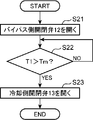
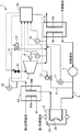
- FIG. 1 It is a figure showing the outline of the composition of the exhaust heat recovery system concerning one embodiment of the present invention. It is sectional drawing which shows the structure of the pump which the waste heat recovery system shown in FIG. 1 has. It is a flowchart which shows an example of the control which opens the cooling side opening / closing part by the control part which the exhaust heat recovery system shown in FIG. 1 has. It is a flowchart which shows the other example of control which opens the cooling side opening / closing part by the control part which the exhaust heat recovery system shown in FIG. 1 has. 7 is a flowchart showing still another example of control for opening the cooling side opening / closing unit by the control unit of the exhaust heat recovery system shown in FIG. 1.
- 7 is a flowchart showing still another example of control for opening the cooling side opening / closing unit by the control unit of the exhaust heat recovery system shown in FIG. 1.
- 7 is a flowchart showing still another example of control for opening the cooling side opening / closing unit by the control unit of the exhaust heat recovery system shown in FIG. 1.
- 7 is a flowchart showing still another example of control for opening the cooling side opening / closing unit by the control unit of the exhaust heat recovery system shown in FIG. 1. It is a figure which shows the outline of a structure of the waste heat recovery system which concerns on other embodiment of this invention.
- the exhaust heat recovery system 1 includes an evaporator 2, an expander 3, a power recovery device 4, a condenser 5, a circulation pump 7, and a preheater 18.
- the circulation channel 6 is provided.
- the evaporator 2, the expander 3, the condenser 5, the circulation pump 7, and the preheater 18 are connected in series to the circulation channel 6 in this order.
- the working medium circulates in the circulation channel 6.
- This exhaust heat recovery system 1 includes a cooling medium pipe 8 communicating between the outlet side of the circulation pump 7 and the inlet side of the condenser 5 and an expander 3 as pipes connected to the circulation flow path 6. Further provided is a bypass pipe 9 that bypasses and communicates between the evaporator 2 and the condenser 5.
- One end of the cooling medium pipe 8 is connected between the circulation pump 7 and the preheater 18 in the circulation channel 6, and the other end is connected between the expander 3 and the condenser 5 in the circulation channel 6.
- One end of the bypass pipe 9 is connected between the evaporator 2 and the expander 3 in the circulation channel 6, and the other end is connected between the expander 3 and the condenser 5 in the circulation channel 6.
- the preheater 18 may be omitted, and in this case, one end portion of the cooling medium pipe 8 is connected between the circulation pump 7 and the evaporator 2 in the circulation flow path 6.
- the exhaust heat recovery system 1 further includes an opening / closing valve 11 provided on the inlet side of the expander 3 in the circulation flow path 6 and a bypass side opening / closing provided in the bypass pipe 9 as a valve for controlling the flow of the working medium.
- a valve 12 and a cooling side opening / closing valve 13 provided in the cooling medium pipe 8 are provided.
- the exhaust heat recovery system 1 includes a temperature detection unit (temperature detection sensor) 14 that detects the temperature of the working medium flowing into the condenser 5 and an outlet of the expander 3 in order to detect the temperature and pressure of the working medium.
- a first pressure detection unit (first pressure detection sensor) 15 that detects the pressure of the working medium on the side
- a second pressure detection unit (second pressure detection sensor) that detects the pressure of the working medium on the outlet side of the evaporator 2 16
- a third pressure detection unit (third pressure detection sensor) 17 for detecting the pressure of the working medium on the outlet side of the circulation pump 7.
- the exhaust heat recovery system 1 includes a control unit 10 capable of performing on / off control of the on-off valve 11, the bypass-side on-off valve 12, and the cooling-side on-off valve 13.
- the evaporator 2 heats and evaporates (gasifies) the working medium by exchanging heat between the heating medium such as high-temperature steam and the liquid working medium.
- the evaporator 2 includes a first flow path 2a through which a high-heat heating medium such as steam or hot water flows, and a second flow path 2b through which a working medium flows.
- the preheater 18 is provided between the circulation pump 7 and the evaporator 2.
- the preheater 18 has a configuration similar to that of the evaporator 2, and includes a first flow path 18 a through which a high-temperature heating medium exiting the first flow path 2 a of the evaporator 2 flows, and an upstream side of the evaporator 2. And a second flow path 18b through which the working medium flows.
- the preheater 18 can preheat the working medium introduced into the evaporator 2 by exchanging heat between the working medium upstream of the evaporator 2 and a high-heat heating medium.
- a superheater that further superheats the working medium evaporated in the evaporator 2 may be provided on the downstream side of the evaporator 2.
- the expander 3 is provided in a portion of the circulation channel 6 on the downstream side of the evaporator 2.
- the expander 3 for example, a positive displacement screw expander having a rotor that is rotationally driven by the expansion energy of the gaseous working medium exiting from the evaporator 2 is used.
- a gaseous working medium supplied to the rotor chamber is introduced from an intake port formed in a casing (not shown) and is expanded in the rotor chamber.
- the rotor is rotationally driven by the expansion energy generated at this time.
- the working medium whose pressure is reduced by expanding in the rotor chamber is discharged to the circulation flow path 6 from the discharge port formed in the casing.
- the expander 3 is not limited to a positive displacement screw expander, but may be a centrifugal type or a scroll type.
- the power recovery machine 4 is connected to the rotating shaft of the expander 3.
- a power generator is used as the power recovery machine 4.
- This power recovery machine 4 has a rotating shaft connected to the rotor of the expander 3.
- the power recovery machine 4 generates electric power by rotating the rotating shaft as the rotor rotates.
- a compressor or the like may be used in addition to the generator.
- the condenser 5 is provided in a portion of the circulation channel 6 on the downstream side of the expander 3.
- the condenser 5 condenses (liquefies) the working medium by cooling the gaseous working medium after being expanded by the expander 3 with a cooling medium.
- the condenser 5 includes a first flow path 5a through which a cooling medium such as water flows, and a second flow path 5b through which a working medium flowing out from the expander 3 flows.
- a brazing plate heat exchanger or the like is used as the condenser 5, for example.
- the brazing plate heat exchanger has a first plate with grooves functioning as a flow path for the working medium formed on the surface and a second plate with grooves formed on the surface functioning as a flow path for the cooling medium.
- It has a laminated structure.
- a working medium flow path and a cooling medium flow path are formed in the laminate of the first plate and the second plate.
- the laminated body is brazed so that the pipe connected to the pipe constituting the circulation flow path 6 communicates with the flow path of the working medium.
- the laminated body is brazed so that a pipe connected to a pipe constituting the cooling medium circuit communicates with a flow path of the cooling medium.
- the circulation pump 7 is provided in a portion of the circulation flow path 6 on the downstream side of the condenser 5 (that is, a portion between the condenser 5 and the preheater 18).
- the circulation pump 7 pressurizes the liquid working medium condensed by the condenser 5 to a predetermined pressure, and pumps it to the preheater 18 on the downstream side of the circulation pump 7 in the circulation flow path 6.
- the circulation pump 7 for example, a magnet drive type pump is used.
- the circulation pump 7 includes a motor 7a, a casing 7b, an impeller 7c rotatably accommodated inside the casing 7b, and a driven permanent magnet incorporated in the impeller 7c. 7d and a drive-side permanent magnet 7e connected to the rotating shaft of the motor 7a via a bracket.
- the driving-side permanent magnet 7e is rotated around the rotation axis of the motor 7a by the driving force of the motor 7a
- the impeller 7c inside the casing 7b is driven by the driven-side permanent magnet 7d incorporated in the impeller 7c. It is possible to rotate by the force attracted to.
- the circulation pump 7 is not limited to the above configuration, and may be another configuration, for example, a gear pump in which the rotor includes a pair of gears.
- the cooling medium pipe 8 is connected to the circulation flow path 6 and communicates between the outlet side of the circulation pump 7 and the inlet side of the condenser 5.
- the cooling medium pipe 8 divides a part of the liquid working medium sent from the circulation pump 7 and flows into the condenser 5 without going through the evaporator 2.
- the bypass pipe 9 connects the outlet side of the evaporator 2 and the inlet side of the condenser 5 in the circulation flow path 6, whereby the expander is connected between the evaporator 2 and the condenser 5 in the circulation flow path 6. It bypasses 3 and communicates.
- the on-off valve 11 is disposed between the connection portion of the bypass pipe 9 and the expander 3 in the circulation flow path 6. That is, the on-off valve 11 is provided on the inlet side of the expander 3 in the circulation flow path 6.
- the on-off valve 11 is constituted by a closing valve that switches between an open state and a closed state.
- the on-off valve 11 may be a flow rate adjustment valve that can arbitrarily adjust the flow rate of the working medium flowing into the expander 3.
- the bypass side opening / closing valve 12 is provided in the middle of the bypass pipe 9 and functions as a bypass side opening / closing part that opens and closes the bypass pipe 9.
- the bypass side on-off valve 12 is a closing valve that switches between an open state and a closed state.
- the bypass-side on-off valve 12 is controlled by the control unit 10 so as to open when the heat recovery system 1 is stopped (during both normal stop and emergency stop) or when the operation is started. As a result, when the operation is stopped or the operation is started, it is possible to make a detour to the downstream side of the expander 3 through the bypass pipe 9.
- the cooling side opening / closing valve 13 is provided in the cooling medium pipe 8.
- the cooling side opening / closing valve 13 functions as a switching unit that switches between a state in which the liquid working medium can be introduced into the condenser 5 through the cooling medium pipe 8 and a state in which the liquid working medium cannot be introduced.
- the cooling side on-off valve 13 is configured by a closing valve that switches between an open state and a closed state.
- the cooling side on-off valve of the present invention only needs to have a configuration capable of switching between a state allowing the working medium to flow into the condenser 5 through the cooling medium pipe 8 and a state where the working medium cannot flow. Therefore, the switching unit may be constituted by a three-way valve provided in a portion where the cooling medium pipe 8 branches from the circulation flow path 6 instead of the cooling side opening / closing valve.
- the temperature detector 14 is provided on the inlet side (upstream side) of the condenser 5.
- the temperature detection unit 14 can detect the temperature of the working medium flowing into the condenser 5.
- the first pressure detection unit 15 is provided on the outlet side (downstream side) of the expander 3 and functions as an expander outlet side pressure detection unit that detects the pressure of the working medium flowing out of the expander 5.
- the second pressure detection unit 16 is provided on the outlet side (downstream side) of the evaporator 2 and functions as an evaporator outlet side pressure detection unit that detects the pressure of the gaseous working medium discharged from the evaporator 2. .
- the third pressure detector 17 is provided on the downstream side (exit side) of the circulation pump 7 and detects the pressure of the working medium discharged from the circulation pump 7. Note that the third pressure detection unit 17 may be omitted.
- the exhaust heat recovery system 1 of the present embodiment is connected to the circulation flow path 6, and a cooling medium for diverting a part of the working medium sent from the circulation pump 7 to flow into the condenser 5.
- a pipe 8 a cooling side on-off valve 13 capable of switching between a state in which the working medium can flow into the cooling medium pipe 8 and a state in which the working medium cannot flow, and a control unit 10 that controls switching of the cooling side on-off valve 13. Yes.
- the control unit 10 sets the cooling side so that the working medium can flow into the cooling medium pipe 8.
- the on-off valve 13 is controlled. That is, the control unit 10 controls to open the cooling side on-off valve 13.
- the low-temperature working medium before being heated by the evaporator 2 in the circulation channel 6 passes through the cooling medium pipe 8 and then merges with the high-temperature working medium exiting from the evaporator 2.
- the high temperature working medium can be cooled by the liquid working medium, it is possible to reduce the possibility that the condenser 5 is deteriorated or broken by the heat of the working medium.
- the condenser 5 when the condenser 5 has a structure of a brazing plate type condenser in which a plurality of plates are brazed to a pipe, the brazed portion is deteriorated or damaged by heat. It is possible to reduce the fear.
- the control unit 10 compares the temperature T1 detected by the temperature detection unit 14 with a preset temperature (threshold) Tm. As a result, when it is detected that the temperature T1 of the working medium is equal to or higher than the predetermined temperature Tm (in the case of YES at step S1), the control unit 10 performs the predetermined temperature Tm of the working medium by the temperature detection unit 14. Based on the detection of the temperature T1, the cooling on / off valve 13 is controlled to open (step S2). That is, the cooling side opening / closing valve 13 is switched to a state in which the working medium can flow into the cooling medium pipe 8. Note that when the temperature T1 of the working medium drops below a predetermined temperature Tm after step S2, the control unit 10 may perform control so that the cooling on-off valve 13 is closed.
- the temperature of the working fluid is detected by the temperature detection unit 14 before the working medium heated by the evaporator 2 reaches the inlet of the condenser 5. .
- the control unit 10 performs control to switch the cooling side on-off valve 13 to a state in which the working medium can flow into the cooling medium pipe 8. That is, the control unit 10 performs control to open the cooling side on-off valve 13.
- the low-temperature working medium before being heated by the evaporator 2 passes through the cooling medium pipe 8 and joins the high-temperature working medium that has come out of the evaporator 2 to cool the high-temperature working medium. Therefore, it is possible to reduce the possibility that the condenser 5 is deteriorated or damaged by the heat of the working medium.
- the high-temperature working medium exiting from the evaporator 2 reaches the upstream side of the condenser 5 through the bypass pipe 9 that bypasses the expander 3, the high-temperature working medium remains in the cooling medium pipe. It is cooled by the low-temperature working medium before flowing into the condenser 5 through 8. Accordingly, even in the exhaust heat recovery system 1 having the bypass pipe 9 as shown in FIG. 1, it is possible to reliably reduce the possibility that the condenser 5 is deteriorated or damaged by the heat of the working medium.
- the condition that the temperature of the working medium flowing into the condenser 5 becomes higher than a predetermined temperature is considered to be satisfied in the following cases.
- the control unit 10 controls the temperature detected by the temperature detection unit 14 when the bypass side on-off valve 12 opens. Regardless, control is performed to switch the cooling side on-off valve 13 so that the working medium can flow into the cooling medium pipe 8.
- control unit 10 first performs control to open the bypass side on-off valve 12 (step S11), and then performs control to open the cooling side on-off valve 13 (step S11). Step S12).
- the timing for opening the bypass-side on-off valve 12 and the timing for opening the cooling-side on-off valve 13 may be simultaneous, or either one may be first.
- the control unit 10 switches the cooling side on / off valve 13 to a state in which the working medium can flow into the cooling medium pipe 8 regardless of the temperature of the working medium when the bypass side on / off valve 12 is opened. I do.
- the low-temperature working medium before being heated by the evaporator 2 joins the high-temperature working medium flowing from the bypass pipe 9 before being introduced into the condenser 5 through the cooling medium pipe 8. Therefore, since the high-temperature working medium is cooled before flowing into the condenser 5, it is possible to reliably reduce the possibility that the condenser 5 is deteriorated or damaged by the heat of the working medium. In this case, a configuration in which the temperature detection unit 14 is omitted is possible.
- the control unit 10 first performs control to open the bypass side on-off valve 12 (step S21).
- the control unit 10 performs control to open the cooling side on-off valve 13 (Ste S23).
- the control unit 10 performs control to switch the cooling side opening / closing valve 13 so that the working medium can flow into the cooling medium pipe 8.
- step S ⁇ b> 31 when the control unit 10 starts an operation stop operation based on reception of an operation stop signal or the like (step S ⁇ b> 31), the control unit 10 supplies the circulation pump 7. Then, a stop command is given (step S32), and control is performed to open the bypass side on-off valve 12 (step S33). As a result, the working medium starts a bypass operation through the bypass pipe 9. While the circulation pump 7 receiving the stop command is gradually stopped driving, the control unit 10 performs control to open the cooling side on-off valve 13 (step S34). Thereby, the cooling side on-off valve 13 is switched to a state in which the liquid working medium discharged from the circulation pump 7 can flow into the cooling medium pipe 8.
- Step S35 the control unit 10 first controls the bypass-side on / off valve 12 (step S35), and then controls the on-off valve 11 to close. (Step S36). Thereby, a series of operation stop operation
- step S36 may be performed before the operation of closing the bypass-side on-off valve 12 in step S35. Or you may close the on-off valve 11 and the bypass side on-off valve 12 simultaneously.
- the on-off valve 11 may be gradually closed.
- Control for opening the cooling side on-off valve 13 when the pressure of the working medium on the outlet side of the evaporator 2 is equal to or higher than a predetermined pressure The temperature of the working medium heated and evaporated by the evaporator 2 rises to a predetermined temperature or higher When this occurs, the pressure of the working medium also rises above a predetermined pressure. Therefore, in this control, the control unit 10 is based on the pressure detection of the working medium on the outlet side of the evaporator 2 by the second pressure detection unit 16 (evaporator outlet side pressure detection unit) instead of the temperature detection of the working medium. Thus, control is performed to switch the cooling side opening / closing valve 13 to a state in which the working medium can flow into the cooling medium pipe 8.
- control unit 10 first compares the detection pressure P1 detected by the second pressure detection unit 16 with a preset pressure Pm. As shown in the flowchart of FIG. 7, when the pressure P1 of the working medium detected by the second pressure detector 16 is equal to or higher than a predetermined pressure Pm (in the case of YES in step S41), control is performed.
- the unit 10 performs control to open the cooling on-off valve 13 based on the detection of the pressure P1 equal to or higher than the predetermined pressure Pm of the working medium by the second pressure detection unit 16 (step S42). Thereby, the low-temperature working medium before being heated by the evaporator 2 flows into the condenser 5 through the cooling medium pipe 8.
- the high-temperature working medium exiting from the evaporator 2 is cooled by the low-temperature working medium, so that it is possible to reduce the possibility that the condenser 5 is deteriorated or damaged by the heat of the working medium.
- the high-temperature working medium heated by the evaporator 2 when the operation is stopped is bypass pipe 9
- the control unit 10 is based on the pressure detection of the working medium on the outlet side of the expander 2 by the first pressure detection unit 15 (expander outlet side pressure detection unit) instead of the temperature detection of the working medium.
- control is performed to switch the cooling side opening / closing valve 13 to a state in which the working medium can flow into the cooling medium pipe 8.
- control unit 10 first compares the pressure P2 detected by the first pressure detection unit 15 with a preset pressure Pn. As shown in the flowchart of FIG. 8, when the pressure P2 of the working medium detected by the first pressure detector 15 is equal to or higher than a predetermined pressure Pn (in the case of YES in step S51), the controller 10 performs control to open the cooling on-off valve 13 based on the detection of the pressure P2 equal to or higher than the predetermined pressure Pn of the working medium by the second pressure detection unit 16 (step S52). Thereby, the low-temperature working medium before being heated by the evaporator 2 flows into the condenser 5 through the cooling medium pipe 8.
- the high-temperature working medium exiting from the evaporator 2 is cooled by the low-temperature working medium, so that it is possible to reduce the possibility that the condenser 5 is deteriorated or damaged by the heat of the working medium.
- control unit 10 performs control to open the cooling side on-off valve 13 based on the pressure on the outlet side of the evaporator 2 as shown in (3) above.
- one type of heating medium for example, any one of steam and hot water
- the one type of heating medium is supplied to the evaporator 2 and the preheater 18 to heat the working medium.
- the present invention is not limited to this.
- a configuration in which the preheater 18 is omitted may be used.
- a configuration capable of heating the working medium using two types of heating media such as the exhaust heat recovery system 1 shown in FIG. 9, may be used.
- the 9 includes an evaporator 2 to which a first heating medium is supplied and a superheater 19 to which a second heating medium different from the first heating medium is supplied.
- the first heating medium is, for example, a gas such as compressed air compressed by air compression means (such as an engine supercharger).
- the second heating medium is, for example, steam or hot water.
- the evaporator 2 may have a first flow path 2a through which a first heating medium such as compressed air can pass and a second flow path 2b through which the working medium passes through the first flow path 2a. That's fine.
- the 2nd flow path 2b is not restricted to the structure which passes the inside of the 1st flow path 2a.
- the superheater 19 should just be the structure which has the 1st flow path 19a in which 2nd heating media, such as a vapor
- a preheater for preheating the working medium may be provided upstream of the evaporator 2.
- the superheater 19 may not be provided. In this case, the heating medium supplied to the preheater and the heating medium supplied to the evaporator 2 are different media.
- the exhaust heat recovery system includes an evaporator, an expander, a condenser, a pumping unit, and circulation for circulating a working medium between the evaporator, the expander, the condenser, and the pumping unit.
- a switching unit that switches between a possible state and a state that cannot flow, and a control unit that performs switching control of the switching unit.
- the control unit performs switching control of the switching unit so that the working medium can flow into the cooling medium pipe when a condition that the temperature of the working medium flowing into the condenser becomes higher than a predetermined temperature is satisfied. I do.
- the control unit when the condition that the temperature of the working medium flowing into the condenser becomes higher than a predetermined temperature is satisfied, the control unit performs control to switch the switching unit to a state in which the working medium can flow into the cooling medium pipe.
- the low-temperature working medium before being heated by the evaporator in the circulation channel joins the high-temperature working medium that has exited the evaporator through the cooling medium pipe.
- the high temperature working medium is cooled by the low temperature working medium, it is possible to reduce the possibility that the condenser is deteriorated or broken by the heat of the working medium.
- the exhaust heat recovery system may further include a temperature detection unit that detects the temperature of the working medium on the inlet side of the condenser. In this case, it is preferable that the condition is satisfied when the temperature of the working medium detected by the temperature detection unit is equal to or higher than a predetermined temperature.
- the temperature of the working fluid is detected by the temperature detection unit before the working medium heated by the evaporator reaches the inlet of the condenser.
- the control unit performs control to switch the switching unit so that the working medium can flow into the cooling medium pipe.
- the exhaust heat recovery system communicates between the evaporator and the condenser, bypassing the expander, and a bypass pipe for sending the working medium flowing out of the evaporator to the condenser And a bypass-side opening / closing part that opens and closes the bypass pipe.
- the control unit In the configuration having the bypass pipe that bypasses the expander between the evaporator and the condenser as described above, when the temperature of the working fluid detected by the temperature detection unit is equal to or higher than a predetermined temperature, the control unit The switching unit is controlled to switch to a state in which the working medium can flow into the cooling medium pipe.
- the exhaust heat recovery system communicates between the evaporator and the condenser, bypassing the expander, and a bypass pipe for sending the working medium flowing out of the evaporator to the condenser. And a bypass-side opening / closing part that opens and closes the bypass pipe. In this case, the condition may be satisfied by opening the bypass side opening / closing part.
- the bypass-side opening / closing part opens to allow the bypass pipe that bypasses the expander to conduct (so-called bypass operation). Is called.
- bypass operation there is a high possibility that the working medium heated by the evaporator and having a high temperature flows into the condenser through the bypass pipe as it is at a high temperature. Therefore, in this configuration, when the bypass side opening / closing unit is opened, the control unit performs control to switch the switching unit to a state in which the working medium can flow into the cooling medium pipe regardless of the temperature of the working medium.
- the low-temperature working medium before being heated by the evaporator passes through the cooling medium pipe and joins the working medium flowing through the bypass pipe.
- the working medium introduced into the condenser is cooled, it is possible to reliably reduce the possibility that the condenser is deteriorated or damaged by the heat of the working medium.
- the exhaust heat recovery system communicates between the evaporator and the condenser, bypassing the expander, and a bypass pipe for sending the working medium flowing out of the evaporator to the condenser.
- a bypass side opening / closing part that opens and closes the bypass pipe and a temperature detection part that detects the temperature of the working medium on the inlet side of the condenser may be further provided. In this case, the condition may be satisfied when the bypass side opening / closing part is opened and the temperature of the working medium detected by the temperature detection part is equal to or higher than a predetermined temperature.
- the control unit performs control to switch the switching unit so that the working medium can flow into the cooling medium pipe.
- the condition may be satisfied when the exhaust heat recovery system stops operating.
- the control unit performs control to switch the switching unit to a state in which the working medium can flow into the cooling medium pipe when the operation of the exhaust heat recovery system is stopped.
- the working medium discharged from the expander and introduced into the condenser is cooled by the low-temperature working medium flowing through the cooling medium pipe.
- the exhaust heat recovery system may further include an evaporator outlet side pressure detection unit that detects the pressure of the working medium on the outlet side of the evaporator.
- the condition may be satisfied when the pressure of the working medium on the outlet side of the evaporator detected by the evaporator outlet-side pressure detection unit is equal to or higher than a predetermined pressure.
- the control unit performs control to switch the switching unit so that the working medium can flow into the cooling medium pipe. Thereby, the low-temperature working medium before being heated by the evaporator flows into the condenser through the cooling medium piping.
- the high-temperature working medium that has come out of the evaporator is cooled by the low-temperature working medium, so that it is possible to reduce the possibility of the condenser being deteriorated or damaged by the heat of the working medium.
- the exhaust heat recovery system may further include an expander outlet side pressure detection unit that detects the pressure of the working medium on the outlet side of the expander.
- the condition may be satisfied when the pressure of the working medium on the outlet side of the expander detected by the expander outlet side pressure detection unit is equal to or higher than a predetermined pressure.
- the control unit performs control to switch the switching unit so that the working medium can flow into the cooling medium pipe. Thereby, the low-temperature working medium before being heated by the evaporator flows into the condenser through the cooling medium pipe.
- the high-temperature working medium that has come out of the evaporator is cooled by the low-temperature working medium, so that it is possible to reduce the possibility of the condenser being deteriorated or damaged by the heat of the working medium.
- the condenser can be prevented from being deteriorated or damaged by the heat of the working medium.
Landscapes
- Engineering & Computer Science (AREA)
- Chemical & Material Sciences (AREA)
- Combustion & Propulsion (AREA)
- Mechanical Engineering (AREA)
- General Engineering & Computer Science (AREA)
- Control Of Turbines (AREA)
- Engine Equipment That Uses Special Cycles (AREA)
Abstract
排熱回収システム(1)は、蒸発器(2)と、膨張機(3)と、凝縮器(5)と、循環ポンプ(7)と、作動媒体を循環させる循環流路(6)と、循環流路(6)に接続され、循環ポンプ(7)から送出された作動媒体の一部を分流して凝縮器(5)に流入させるための冷却媒体配管(8)と、冷却媒体配管(8)へ作動媒体が流入可能な状態と流入できない状態とを切り換える冷却側開閉弁(13)と、冷却側開閉弁(13)の切換制御をする制御部(10)と、を備えている。制御部(10)は、凝縮器(5)へ流入する作動媒体の温度が所定の温度以上に高くなる条件が成立すると、作動媒体が冷却媒体配管(8)へ流入可能な状態になるように冷却側開閉弁(13)を切り換える制御を行う。
Description
本発明は、排熱回収システムに関する。
従来、エンジンなどから発生する排熱を回収する排熱回収システムが種々提案されている。
特許文献1に記載の排熱回収システムは、加熱媒体と作動媒体とを熱交換させて当該作動媒体を蒸発させる蒸発器と、蒸発器で蒸発した作動媒体を膨張させて回転エネルギーを得る膨張機と、回転エネルギーを他のエネルギーに変換して動力を回収する発電機などの動力回収機と、膨張機から流出した作動媒体を凝縮させる凝縮器とを備えている。作動媒体は、蒸発器、膨張機および凝縮器の間を循環流路を通して循環することが可能である。
また、この排熱回収システムは、膨張機を迂回して蒸発器と凝縮器との間をつなぐバイパス配管と、このバイパス配管を開閉する開閉弁と、膨張機の入口側を開閉する閉鎖弁とをさらに備えている。
排熱回収システムが緊急停止をする場合などでは、膨張機の入口側の閉鎖弁を閉じ、バイパス配管の開閉弁を開く。これにより、蒸発器から出た高温の作動媒体が膨張機へ流入することを防ぐとともに、バイパス配管を通して膨張機の下流側へ迂回させることが可能である。
上記の排熱回収システムでは、バイパス配管の開閉弁が開かれたときに、バイパス配管を通して膨張機の下流側へ迂回した高温の作動媒体が凝縮器に流入する。このため、凝縮器が作動媒体の熱によって劣化や破損するおそれがある。
本発明の目的は、凝縮器が作動媒体の熱によって劣化や破損することを防ぐことが可能な排熱回収システムを提供することである。
本発明の一局面による排熱回収システムは、蒸発器と、膨張機と、凝縮器と、圧送部と、前記蒸発器、膨張機、凝縮器および圧送部の間で作動媒体を循環させる循環流路と、前記循環流路に接続され、前記圧送部から送出された作動媒体の一部を分流して前記凝縮器に流入させるための冷却媒体配管と、前記冷却媒体配管へ作動媒体が流入可能な状態と流入できない状態とを切り換える切換部と、前記切換部の切換制御をする制御部と、を備えている。前記制御部は、前記凝縮器へ流入する作動媒体の温度が所定の温度以上に高くなる条件が成立すると、作動媒体が前記冷却媒体配管へ流入可能な状態になるように前記切換部の切換制御を行う。
以下、図面を参照しながら本発明の排熱回収システムの実施形態についてさらに詳細に説明する。
本実施形態に係る排熱回収システム1は、図1に示されるように、蒸発器2と、膨張機3と、動力回収機4と、凝縮器5と、循環ポンプ7と、予熱器18と、循環流路6とを備えている。循環流路6には、蒸発器2、膨張機3、凝縮器5、循環ポンプ7、および予熱器18がこの順に直列に接続されている。循環流路6には、作動媒体が循環する。
この排熱回収システム1は、上記の循環流路6に接続された配管として、循環ポンプ7の出口側と凝縮器5の入口側との間を連通する冷却媒体配管8と、膨張機3を迂回して蒸発器2と凝縮器5との間を連通するバイパス配管9とをさらに備えている。冷却媒体配管8の一端部は、循環流路6における循環ポンプ7と予熱器18との間に接続され、他端部は、循環流路6における膨張機3と凝縮器5との間に接続されている。バイパス配管9の一端部は、循環流路6における蒸発器2と膨張機3との間に接続され、他端部は、循環流路6における膨張機3と凝縮器5との間に接続されている。なお、予熱器18は、省略されてもよく、この場合、冷却媒体配管8の一端部は、循環流路6における循環ポンプ7と蒸発器2との間に接続されることになる。
排熱回収システム1は、さらに、作動媒体の流れを制御する弁として、循環流路6のうち膨張機3の入口側に設けられた開閉弁11と、バイパス配管9に設けられたバイパス側開閉弁12と、冷却媒体配管8に設けられた冷却側開閉弁13とを備えている。
さらに、排熱回収システム1は、作動媒体の温度や圧力を検出するために、凝縮器5に流入する作動媒体の温度を検出する温度検出部(温度検出センサー)14と、膨張機3の出口側の作動媒体の圧力を検出する第1圧力検出部(第1圧力検出センサー)15と、蒸発器2の出口側の作動媒体の圧力を検出する第2圧力検出部(第2圧力検出センサー)16と、循環ポンプ7の出口側の作動媒体の圧力を検出する第3圧力検出部(第3圧力検出センサー)17とを備えている。
さらに排熱回収システム1は、上記の開閉弁11、バイパス側開閉弁12および冷却側開閉弁13の開閉制御を行うことが可能な制御部10を備えている。
つぎに、上記の排気回収システム1の各構成要素についてさらに詳細に説明する。
蒸発器2は、高熱の蒸気などの加熱媒体と液状の作動媒体とを熱交換させることによって作動媒体を加熱して蒸発(ガス化)させる。具体的には、蒸発器2は、蒸気や温水などの高熱の加熱媒体が流れる第1流路2aと、作動媒体が流れる第2流路2bとを有する。
本実施形態では、予熱器18が、循環ポンプ7と蒸発器2との間に設けられている。この予熱器18は、蒸発器2と同様な構成を有し、蒸発器2の第1流路2aを出た高熱の加熱媒体が流れる第1流路18aと、蒸発器2よりも上流側の作動媒体が流れる第2流路18bとを有する。予熱器18は、蒸発器2の上流側の作動媒体を高熱の加熱媒体と熱交換させることによって、蒸発器2に導入される作動媒体を予熱することが可能である。なお、蒸発器2の下流側において、蒸発器2で蒸発した作動媒体をさらに過熱する過熱器が設けられてもよい。
膨張機3は、循環流路6のうち蒸発器2の下流側の部位に設けられている。本実施形態では、膨張機3としては、例えば、蒸発器2から出たガス状の作動媒体の膨張エネルギーにより回転駆動されるロータを有する容積式のスクリュー膨張機などが用いられる。膨張機3では、図略のケーシングに形成された吸気口からロータ室に供給されたガス状の作動媒体を導入してロータ室内で膨張させる。このとき発生する膨張エネルギーによってロータが回転駆動される。そして、ロータ室内で膨張することにより圧力が低下した作動媒体は、前記ケーシングに形成された排出口から循環流路6に排出される。なお、膨張機3としては、容積式のスクリュー膨張機に限らず、遠心式のものやスクロールタイプのもの等が用いられてもよい。
動力回収機4は、膨張機3の回転軸に接続されている。本実施形態では、動力回収機4として発電機が用いられている。この動力回収機4は、膨張機3のロータに接続された回転軸を有している。動力回収機4は、前記回転軸がロータの回転に伴って回転することにより電力を発生させる。なお、動力回収機4として、発電機の他、圧縮機等が用いられてもよい。
凝縮器5は、循環流路6のうち膨張機3の下流側の部位に設けられている。凝縮器5は、膨張機3で膨張した後のガス状の作動媒体を冷却媒体で冷却することにより作動媒体を凝縮(液化)させる。具体的に、凝縮器5は、水などの冷却媒体が流れる第1流路5aと、膨張機3から流出した作動媒体が流れる第2流路5bとを有する。凝縮器5は、例えば、ブレージングプレート式熱交換器などが用いられる。ブレージングプレート式熱交換器は、作動媒体の流路として機能する溝が表面に形成された第1プレートと、冷却媒体の流路として機能する溝が表面に形成された第2プレートとが交互に積層された構造を有する。第1プレートと第2プレートとの積層体には、作動媒体の流路と冷却媒体の流路とが形成される。積層体には、循環流路6を構成する配管に繋がるパイプが、作動媒体の流路に連通するように、ろう付けされている。また積層体には、冷却媒体回路を構成する配管に繋がるパイプが、冷却媒体の流路に連通するように、ろう付けされている。
循環ポンプ7は、循環流路6における凝縮器5の下流側の部位(すなわち、凝縮器5と予熱器18との間の部位)に設けられている。循環ポンプ7は、凝縮器5で凝縮された液状の作動媒体を所定の圧力まで加圧して循環流路6における当該循環ポンプ7の下流側の予熱器18に圧送する。
本実施形態では、循環ポンプ7としては、例えば、マグネットドライブ式のポンプが用いられる。具体的には、図2に示されるように、循環ポンプ7は、モータ7aと、ケーシング7bと、ケーシング7b内部に回転自在に収納されたインペラ7cと、インペラ7cに組み込まれた従動側永久磁石7dと、モータ7aの回転軸にブラケットを介して連結された駆動側永久磁石7eとを備えている。モータ7aの駆動力によって駆動側永久磁石7eをモータ7aの回転軸を中心に回転させると、ケーシング7b内部のインペラ7cは、当該インペラ7cに組み込まれた従動側永久磁石7dが駆動側永久磁石7eに引き寄せられる力によって回転することが可能である。ケーシング7b内には、インペラ7cの回転によって作動媒体が導入される。この構成では、ケーシング7bを貫通してモータ7aとインペラ7cとをつなぐ部分が不要になるので、ケーシング7bのシール性が向上し、作動媒体の漏れのおそれが低減する。なお、循環ポンプ7は、上記の構成に限定されるものではなく、他の構成、例えば、ロータが一対のギアからなるギアポンプ等であってもよい。
冷却媒体配管8は、循環流路6に接続され、循環ポンプ7の出口側と凝縮器5の入口側との間を連通する。冷却媒体配管8は、循環ポンプ7から送出された液状の作動媒体の一部を分流して、蒸発器2を経由することなく凝縮器5に流入させる。
バイパス配管9は、循環流路6における蒸発器2の出口側と凝縮器5の入口側とを接続し、これにより、循環流路6において、蒸発器2と凝縮器5との間を膨張機3を迂回して連通する。
開閉弁11は、循環流路6においてバイパス配管9の接続部と膨張機3との間に配置されている。すなわち、開閉弁11は、循環流路6のうち膨張機3の入口側に設けられている。開閉弁11は、開状態と閉状態とを切り換える閉鎖弁によって構成される。なお、開閉弁11は、膨張機3へ流入する作動媒体の流量を任意に調整可能な流量調整弁でもよい。
バイパス側開閉弁12は、バイパス配管9の途中に設けられ、当該該バイパス配管9を開閉するバイパス側開閉部として機能する。バイパス側開閉弁12は、開状態と閉状態とを切り換える閉鎖弁である。バイパス側開閉弁12は、熱回収システム1の運転停止時(通常の停止時および緊急停止時の両方)や運転立ち上げ時などにおいて開くように制御部10によって制御される。これにより、運転停止時や運転立ち上げ時には、バイパス配管9を通して膨張機3の下流側へ迂回させることが可能である。
冷却側開閉弁13は、冷却媒体配管8に設けられている。冷却側開閉弁13は、当該冷却媒体配管8を通して凝縮器5への液状の作動媒体の流入を可能にする状態と流入できない状態とを切り換える切換部として機能する。本実施形態では、冷却側開閉弁13は、開状態と閉状態とを切り換える閉鎖弁によって構成される。なお、本発明の冷却側開閉弁は、冷却媒体配管8を通して凝縮器5への作動媒体の流入を可能にする状態と流入できない状態とを切り換えることが可能な構成を有していればよい。したがって、切換部は、冷却側開閉弁に代えて、循環流路6から冷却媒体配管8が分岐する部分に設けられた三方弁によって構成されていてもよい。
温度検出部14は、凝縮器5の入口側(上流側)に設けられている。温度検出部14は、凝縮器5に流入する作動媒体の温度を検出することが可能である。
第1圧力検出部15は、膨張機3の出口側(下流側)に設けられ、当該膨張機5から流出した作動媒体の圧力を検出する膨張機出口側圧力検出部として機能する。
第2圧力検出部16は、蒸発器2の出口側(下流側)に設けられ、当該蒸発器2から排出されたガス状の作動媒体の圧力を検出する蒸発器出口側圧力検出部として機能する。
第3圧力検出部17は、循環ポンプ7の下流側(出口側)に設けられ、当該循環ポンプ7から吐出された作動媒体の圧力を検出する。なお、第3圧力検出部17は省略されてもよい。
本実施形態の排熱回収システム1は、上記のように、循環流路6に接続され、循環ポンプ7から送出された作動媒体の一部を分流して凝縮器5に流入させるための冷却媒体配管8と、冷却媒体配管8へ作動媒体が流入可能な状態と流入できない状態とを切り換え可能な冷却側開閉弁13と、冷却側開閉弁13の切換制御をする制御部10と、を備えている。
制御部10は、凝縮器5へ流入する作動媒体の温度が予め定められた所定の温度以上に高くなる条件が成立すると、作動媒体が冷却媒体配管8へ流入可能な状態になるように冷却側開閉弁13を制御する。すなわち、制御部10は、冷却側開閉弁13を開くように制御する。これにより、循環流路6における蒸発器2によって加熱される前の低温の作動媒体が、冷却媒体配管8を通った後、蒸発器2から出た高温の作動媒体と合流する。この結果、液状の作動媒体によって高温の作動媒体を冷却することができるので、凝縮器5が作動媒体の熱によって劣化や破損するおそれを低減することが可能である。特に、本実施形態のように、凝縮器5が複数のプレートがパイプにろう付けされたブレージングプレート式凝縮器の構造を有している場合には、ろう付け部分が熱によって劣化や破損されるおそれを低減することが可能である。
冷却側開閉弁13に対する具体的な制御が、図3のフローチャートに例示される。この制御において、制御部10は、温度検出部14による検出温度T1と、予め設定された温度(閾値)Tmとの比較を行う。その結果、作動媒体の温度T1が所定の温度Tm以上であることが検出された場合(ステップS1のYESの場合)には、制御部10は、温度検出部14による作動媒体の所定の温度Tm以上の温度T1の検出に基づいて、冷却開閉弁13を開くように制御する(ステップS2)。すなわち、冷却側開閉弁13が、作動媒体が冷却媒体配管8へ流入可能な状態に切り換えられる。なお、ステップS2の後に作動媒体の温度T1が所定の温度Tm未満まで低下したときには、制御部10は、冷却開閉弁13を閉じるように制御すればよい。
この図3のフローチャートにおける冷却側開閉弁13の制御では、蒸発器2によって加熱された作動媒体が凝縮器5の入口に到達する前に、当該作動流体の温度が温度検出部14によって検出される。検出された温度が所定の温度以上である場合には、制御部10は、冷却側開閉弁13を作動媒体が冷却媒体配管8へ流入可能な状態に切り換える制御を行う。すなわち、制御部10は冷却側開閉弁13を開くように制御する。これにより、蒸発器2によって加熱される前の低温の作動媒体が、冷却媒体配管8を通って、蒸発器2から出た高温の作動媒体に合流して当該高温の作動媒体を冷却する。そのため、凝縮器5が作動媒体の熱によって劣化や破損するおそれを低減することが可能である。
特に、蒸発器2から出た高温の作動媒体が、膨張機3を迂回するバイパス配管9を通って凝縮器5の上流側に高温のまま到達した場合でも、高温の作動媒体は、冷却媒体配管8を通って凝縮器5に流入される前の低温の作動媒体によって冷却される。したがって、図1のようにバイパス配管9を有する構成の排熱回収システム1においても、凝縮器5が作動媒体の熱によって劣化や破損するおそれを確実に低減することが可能である。
ここで、凝縮器5へ流入する作動媒体の温度が所定の温度以上に高くなる条件は、以下の場合などで成立すると考えられる。
(1)バイパス側開閉弁12が開いた場合
(2)バイパス側開閉弁12が開き、かつ、温度検出部14によって検出された温度が所定の温度以上である場合
(3)排熱回収システム1の運転停止時の場合
(4)第2圧力検出部16によって検出された蒸発器2の出口側の作動媒体の圧力が所定の圧力以上の場合
(5)第1圧力検出部15によって検出された膨張機3の出口側の作動媒体の圧力が所定の圧力以上の場合
そこで、本発明の他の実施形態では、上記の(1)~(5)のそれぞれの場合において、冷却側開閉弁13を開く制御が行われる。以下、上記の(1)~(5)のそれぞれの場合についての制御を順に説明する。
(2)バイパス側開閉弁12が開き、かつ、温度検出部14によって検出された温度が所定の温度以上である場合
(3)排熱回収システム1の運転停止時の場合
(4)第2圧力検出部16によって検出された蒸発器2の出口側の作動媒体の圧力が所定の圧力以上の場合
(5)第1圧力検出部15によって検出された膨張機3の出口側の作動媒体の圧力が所定の圧力以上の場合
そこで、本発明の他の実施形態では、上記の(1)~(5)のそれぞれの場合において、冷却側開閉弁13を開く制御が行われる。以下、上記の(1)~(5)のそれぞれの場合についての制御を順に説明する。
(1)バイパス側開閉弁12が開かれた場合における冷却側開閉弁13を開く制御
排熱回収システム1における運転立ち上げ時、停止動作時、または緊急停止時などでは、制御部10がバイパス側開閉弁12を開く。これにより、膨張機3を迂回するバイパス配管9を導通可能にした運転(いわゆるバイパス運転)が行われる。この場合、蒸発器2で加熱されて高温になった作動媒体がバイパス配管9を通って高温のまま凝縮器5へ流入する可能性が高い。そこで、上記のように排熱回収システム1がバイパス配管9およびバイパス側開閉弁12を備えた構成において、制御部10は、バイパス側開閉弁12が開くときに、温度検出部14による検出温度に拘わらず、作動媒体が冷却媒体配管8へ流入可能な状態に冷却側開閉弁13を切り換える制御を行う。
排熱回収システム1における運転立ち上げ時、停止動作時、または緊急停止時などでは、制御部10がバイパス側開閉弁12を開く。これにより、膨張機3を迂回するバイパス配管9を導通可能にした運転(いわゆるバイパス運転)が行われる。この場合、蒸発器2で加熱されて高温になった作動媒体がバイパス配管9を通って高温のまま凝縮器5へ流入する可能性が高い。そこで、上記のように排熱回収システム1がバイパス配管9およびバイパス側開閉弁12を備えた構成において、制御部10は、バイパス側開閉弁12が開くときに、温度検出部14による検出温度に拘わらず、作動媒体が冷却媒体配管8へ流入可能な状態に冷却側開閉弁13を切り換える制御を行う。
具体的には、図4に示されるフローチャートのように、制御部10は、まず、バイパス側開閉弁12を開く制御を行い(ステップS11)、ついで、冷却側開閉弁13を開く制御を行う(ステップS12)。バイパス側開閉弁12を開くタイミングと冷却側開閉弁13を開くタイミングは、同時でもよく、或いは何れかが先でもよい。
上記の制御では、制御部10は、バイパス側開閉弁12が開くときに、作動媒体の温度に関わらず、冷却側開閉弁13を、作動媒体が冷却媒体配管8へ流入可能な状態に切り換える制御を行う。これにより、蒸発器2で加熱される前の低温の作動媒体が冷却媒体配管8を通って凝縮器5へ導入される前に、バイパス配管9から流れてきた高温の作動媒体に合流する。したがって、当該高温の作動媒体が凝縮器5に流入する前に冷却されるので、凝縮器5が作動媒体の熱によって劣化や破損するおそれを確実に低減することが可能である。この場合、温度検出部14を省略した構成が可能となる。
(2)バイパス側開閉弁12が開かれ、かつ、検出された温度が所定の温度以上である場合における冷却側開閉弁13を開く制御
図4の制御例の変形例として、制御部10は、バイパス側開閉弁12を開き、かつ、温度検出部14による検出温度が所定の温度以上である場合に、作動媒体が冷却媒体配管8へ流入可能な状態に冷却側開閉弁13を切り換える制御を行うようにしてもよい。
図4の制御例の変形例として、制御部10は、バイパス側開閉弁12を開き、かつ、温度検出部14による検出温度が所定の温度以上である場合に、作動媒体が冷却媒体配管8へ流入可能な状態に冷却側開閉弁13を切り換える制御を行うようにしてもよい。
具体的には、図5に示されるフローチャートのように、制御部10は、まず、バイパス側開閉弁12を開く制御を行う(ステップS21)。制御部10は、温度検出部14によって検出された作動媒体の温度T1が所定の温度Tm以上であった場合(ステップS22のYESの場合)には、冷却側開閉弁13を開く制御を行う(ステップS23)。
すなわち、バイパス側開閉弁12が開かれて、蒸発器2で加熱された作動媒体が膨張機3を迂回して凝縮器5へ流入されるバイパス運転を行っているときに、凝縮器5の入口側における作動媒体の温度が所定の温度以上になった場合には、制御部10は、作動媒体が冷却媒体配管8へ流入可能な状態に冷却側開閉弁13を切り換える制御を行う。これにより、バイパス配管9を通って凝縮器5へ流入される前の作動媒体が高温の場合には、当該高温の作動媒体が、冷却媒体配管8を通って流れてきた低温の作動媒体によって冷却される。その結果、バイパス運転時において、凝縮器5が作動媒体の熱によって劣化や破損するおそれを確実に低減することが可能である。
しかも、バイパス配管9を通って凝縮器5へ導入される作動媒体が所定の温度未満である場合には、低温の作動媒体が冷却媒体配管8を通して凝縮器5に導入されることがないので、運転効率の低下を抑えることが可能である。
(3)排熱回収システム1の運転停止時の場合における冷却側開閉弁13を開く制御
緊急停止時などの場合に循環ポンプ7の駆動を停止して排熱回収システム1の運転を停止するときには、蒸発器2で加熱されて高温になった作動媒体がバイパス配管9を通って高温のまま凝縮器5へ流入することなどが起こる。この場合、凝縮器5へ流入する作動媒体の温度が所定の温度以上に高くなるおそれがある。そこで、制御部10は、排熱回収システム1の運転停止時に、冷却側開閉弁13を作動媒体が冷却媒体配管8へ流入可能な状態に切り換える制御を行う。
緊急停止時などの場合に循環ポンプ7の駆動を停止して排熱回収システム1の運転を停止するときには、蒸発器2で加熱されて高温になった作動媒体がバイパス配管9を通って高温のまま凝縮器5へ流入することなどが起こる。この場合、凝縮器5へ流入する作動媒体の温度が所定の温度以上に高くなるおそれがある。そこで、制御部10は、排熱回収システム1の運転停止時に、冷却側開閉弁13を作動媒体が冷却媒体配管8へ流入可能な状態に切り換える制御を行う。
具体的には、図6のフローチャートに示されるように、制御部10が運転停止信号の受信などに基づいて運転停止動作を開始するとき(ステップS31)に、制御部10は、循環ポンプ7に対して停止指令を与え(ステップS32)、またバイパス側開閉弁12を開けるように制御する(ステップS33)。これにより、作動媒体がバイパス配管9を通るバイパス運転を開始する。停止指令を受けた循環ポンプ7が徐々に駆動を停止している間、制御部10は、冷却側開閉弁13を開く制御を行う(ステップS34)。これにより、冷却側開閉弁13は、循環ポンプ7から吐出された液状の作動媒体が冷却媒体配管8へ流入可能な状態に切り換わる。そして、冷却側開閉弁13を開いてから、予め設定された一定時間経過後に、制御部10は、まず、バイパス側開閉弁12を閉じ(ステップS35)、ついで、開閉弁11を閉じるように制御する(ステップS36)。これにより、一連の運転停止動作を終了する。
なお、ステップS35のバイパス側開閉弁12を閉じる動作の前に、ステップS36の開閉弁11を閉じる動作を行ってもよい。または、開閉弁11およびバイパス側開閉弁12を同時に閉めてもよい。開閉弁11は、徐々に閉じるようにしてもよい。
この制御では、排熱回収システム1の運転停止時に、膨張機3又はバイパス配管9を流れて凝縮器5に導入される作動媒体は、冷却媒体配管8を通って凝縮器5に流入される前の低温の作動媒体によって冷却される。その結果、排熱回収システム1の運転停止時において、凝縮器5が作動媒体の熱によって劣化や破損するおそれを確実に低減することが可能である。
(4)蒸発器2の出口側の作動媒体の圧力が所定の圧力以上の場合における冷却側開閉弁13を開く制御
蒸発器2によって加熱されて蒸発した作動媒体の温度が所定の温度以上に上昇したときには、当該作動媒体の圧力も所定の圧力以上に上昇する。そこで、この制御では、制御部10は、作動媒体の温度検出の代わりに、第2圧力検出部16(蒸発器出口側圧力検出部)による蒸発器2の出口側の作動媒体の圧力検出に基づいて、冷却側開閉弁13を作動媒体が冷却媒体配管8へ流入可能な状態に切り換える制御を行う。
蒸発器2によって加熱されて蒸発した作動媒体の温度が所定の温度以上に上昇したときには、当該作動媒体の圧力も所定の圧力以上に上昇する。そこで、この制御では、制御部10は、作動媒体の温度検出の代わりに、第2圧力検出部16(蒸発器出口側圧力検出部)による蒸発器2の出口側の作動媒体の圧力検出に基づいて、冷却側開閉弁13を作動媒体が冷却媒体配管8へ流入可能な状態に切り換える制御を行う。
具体的には、制御部10は、まず、第2圧力検出部16による検出圧力P1と、予め設定された圧力Pmとの比較を行う。そして、図7のフローチャートに示されるように、第2圧力検出部16によって検出された作動媒体の圧力P1が、所定の圧力Pm以上であった場合(ステップS41のYESの場合)には、制御部10は、第2圧力検出部16による作動媒体の所定の圧力Pm以上の圧力P1の検出に基づいて、冷却開閉弁13を開く制御を行う(ステップS42)。これにより、蒸発器2によって加熱される前の低温の作動媒体は、冷却媒体配管8を通って凝縮器5に流入する。その結果、蒸発器2から出た高温の作動媒体が低温の作動媒体によって冷却されるので、凝縮器5が作動媒体の熱によって劣化や破損するおそれを低減することが可能である。
(5)膨張機3の出口側の作動媒体の圧力が所定の圧力以上の場合における冷却側開閉弁13を開く制御
運転停止時などにおいて蒸発器2によって加熱された高温の作動媒体がバイパス配管9を通る場合など、膨張機3の出口側の作動媒体の温度が所定の温度以上に上昇したときには、当該作動媒体の圧力も所定の圧力以上に上昇する。そこで、この制御では、制御部10は、作動媒体の温度検出の代わりに、第1圧力検出部15(膨張機出口側圧力検出部)による膨張機2の出口側の作動媒体の圧力検出に基づいて、冷却側開閉弁13を作動媒体が冷却媒体配管8へ流入可能な状態に切り換える制御を行う。
運転停止時などにおいて蒸発器2によって加熱された高温の作動媒体がバイパス配管9を通る場合など、膨張機3の出口側の作動媒体の温度が所定の温度以上に上昇したときには、当該作動媒体の圧力も所定の圧力以上に上昇する。そこで、この制御では、制御部10は、作動媒体の温度検出の代わりに、第1圧力検出部15(膨張機出口側圧力検出部)による膨張機2の出口側の作動媒体の圧力検出に基づいて、冷却側開閉弁13を作動媒体が冷却媒体配管8へ流入可能な状態に切り換える制御を行う。
具体的には、制御部10は、まず、第1圧力検出部15による検出圧力P2と、予め設定された圧力Pnとの比較を行う。そして、図8のフローチャートに示されるように、第1圧力検出部15によって検出された作動媒体の圧力P2が所定の圧力Pn以上であった場合(ステップS51のYESの場合)には、制御部10は、第2圧力検出部16による作動媒体の所定の圧力Pn以上の圧力P2の検出に基づいて、冷却開閉弁13を開く制御を行う(ステップS52)。これにより、蒸発器2によって加熱される前の低温の作動媒体は、冷却媒体配管8を通って、凝縮器5に流入する。その結果、蒸発器2から出た高温の作動媒体が低温の作動媒体によって冷却されるので、凝縮器5が作動媒体の熱によって劣化や破損するおそれを低減することが可能である。
なお、膨張機3の入口において緊急停止時に遮断する緊急遮断弁が設けられている場合には、緊急停止時に膨張機3の出口側の圧力検出ができなくなる。このため、そのような場合には、上記(3)で示されるように制御部10が蒸発器2の出口側の圧力に基づいて冷却側開閉弁13を開く制御を行うのが好ましい。
上記実施形態の排熱回収システム1では、図1に示されるように、作動媒体を加熱するための加熱媒体として1種類の加熱媒体(例えば蒸気や温水のいずれか1種類)が用いられている。そして、当該1種類の加熱媒体が蒸発器2および予熱器18へ供給されて作動媒体が加熱されている。しかしながら、本発明はこれに限定されるものではない。例えば、予熱器18が省略された構成であってもよい。また、本発明のさらに他の実施形態として、図9に示される排熱回収システム1のように、2種類の加熱媒体を用いて作動媒体を加熱することが可能な構成でもよい。例えば、図9に示される排熱回収システム1は、第1加熱媒体が供給される蒸発器2と、第1加熱媒体と異なる第2加熱媒体が供給される過熱器19とを有する。第1加熱媒体は、例えば、空気圧縮手段(エンジンの過給機など)で圧縮された圧縮空気などのガスである。第2加熱媒体は、例えば、蒸気や温水などである。蒸発器2は、圧縮空気などの第1加熱媒体が通過可能な第1流路2aと、当該第1流路2a内を通過して作動媒体が通る第2流路2bとを有する構成であればよい。第2流路2bは第1流路2a内を通過する構成に限られない。また、過熱器19は、蒸気などの第2加熱媒体が通過可能な第1流路19aと、作動媒体が通る第2流路19bとを有する構成であればよい。さらに、蒸発器2の上流側に作動媒体を予熱するための予熱器を設けてもよい。なお、予熱器が設けられる場合には、過熱器19はなくてもよい。この場合、予熱器に供給される加熱媒体と、蒸発器2に供給される加熱媒体とは、異なる媒体となる。
[実施の形態の概要]
ここで、前記実施形態について概説する。
ここで、前記実施形態について概説する。
(1)前記実施形態の排熱回収システムは、蒸発器と、膨張機と、凝縮器と、圧送部と、当該蒸発器、膨張機、凝縮器および圧送部の間で作動媒体を循環させる循環流路と、前記循環流路に接続され、前記圧送部から送出された作動媒体の一部を分流して前記凝縮器に流入させるための冷却媒体配管と、前記冷却媒体配管へ作動媒体が流入可能な状態と流入できない状態とを切り換える切換部と、前記切換部の切換制御をする制御部と、を備える。前記制御部は、前記凝縮器へ流入する作動媒体の温度が所定の温度以上に高くなる条件が成立すると、作動媒体が前記冷却媒体配管へ流入可能な状態になるように前記切換部の切換制御を行う。
かかる構成では、凝縮器へ流入する作動媒体の温度が所定の温度以上に高くなる条件が成立すると、制御部は、作動媒体が冷却媒体配管へ流入可能な状態に切換部を切り換える制御を行う。これにより、循環流路において蒸発器によって加熱される前の低温の作動媒体が、冷却媒体配管を通って蒸発器から出た高温の作動媒体に合流する。この結果、当該高温の作動媒体が低温の作動媒体によって冷却されるので、凝縮器が作動媒体の熱によって劣化や破損するおそれを低減することが可能である。
(2)前記排熱回収システムは、前記凝縮器の入口側における作動媒体の温度を検出する温度検出部をさらに備えていてもよい。この場合、前記条件は、前記温度検出部によって検出された前記作動媒体の温度が所定の温度以上のときに成立するのが好ましい。
かかる構成によれば、蒸発器によって加熱された作動媒体が凝縮器の入口に到達する前に、当該作動流体の温度は、温度検出部によって検出される。検出された温度が所定の温度以上である場合には、制御部は、作動媒体が冷却媒体配管へ流入可能な状態に切換部を切り換える制御を行う。これにより、蒸発器によって加熱される前の低温の作動媒体が、冷却媒体配管を通って、蒸発器から出た高温の作動媒体に合流して当該高温の作動媒体を冷却する。そのため、凝縮器が作動媒体の熱によって劣化や破損するおそれを低減することが可能である。
(3)前記排熱回収システムは、前記蒸発器と前記凝縮器との間を前記膨張機を迂回して連通し、前記蒸発器から流出した作動媒体を前記凝縮器に送るためのバイパス配管と、前記バイパス配管を開閉するバイパス側開閉部とをさらに備えていてもよい。
上記のように蒸発器と凝縮器との間に膨張機を迂回するバイパス配管を有する構成において、温度検出部で検出された作動流体の温度が所定の温度以上である場合には、制御部は、切換部を作動媒体が冷却媒体配管へ流入可能な状態に切り換える制御を行う。これにより、蒸発器から出た高温の作動媒体が、バイパス配管を通って凝縮器に高温のまま到達した場合でも、冷却媒体配管から流れてきた低温の作動媒体によって冷却される。したがって、バイパス配管を有する構成においても、凝縮器が作動媒体の熱によって劣化や破損するおそれを確実に低減することが可能である。
(4)前記排熱回収システムは、前記蒸発器と前記凝縮器との間を前記膨張器を迂回して連通し、前記蒸発器から流出した作動媒体を前記凝縮器に送るためのバイパス配管と、前記バイパス配管を開閉するバイパス側開閉部とをさらに備えていてもよい。この場合、前記条件は、前記バイパス側開閉部が開いたことによって成立してもよい。
排熱回収システムにおける運転立ち上げ時、停止動作時、または緊急停止時などでは、バイパス側開閉部が開くことによって、膨張機を迂回するバイパス配管を導通可能にした運転(いわゆるバイパス運転)が行われる。この場合、蒸発器で加熱されて高温になった作動媒体がバイパス配管を通って高温のまま凝縮器へ流入される可能性が高い。そこで、この構成では、制御部は、バイパス側開閉部を開くときに、作動媒体の温度に関わらず、作動媒体が冷却媒体配管へ流入可能な状態に切換部を切り換える制御を行う。これにより、蒸発器で加熱される前の低温の作動媒体が冷却媒体配管を通って、バイパス配管を通って流れてきた作動媒体に合流する。これにより、凝縮器に導入される作動媒体が冷却されるので、凝縮器が作動媒体の熱によって劣化や破損するおそれを確実に低減することが可能である。
(5)前記排熱回収システムは、前記蒸発器と前記凝縮器との間を前記膨張器を迂回して連通し、前記蒸発器から流出した作動媒体を前記凝縮器に送るためのバイパス配管と、前記バイパス配管を開閉するバイパス側開閉部と、前記凝縮器の入口側における作動媒体の温度を検出する温度検出部と、をさらに備えてもよい。この場合、前記条件は、前記バイパス側開閉部が開き、かつ、前記温度検出部によって検出された前記作動媒体の温度が、所定の温度以上のときに成立してもよい。
かかる構成によれば、バイパス側開閉部が開いて、蒸発器で加熱された作動媒体がバイパス配管を通って凝縮器へ流入するバイパス運転を行っている場合において、凝縮器の入口側における当該作動媒体の温度が所定の温度以上になった場合には、制御部は、作動媒体が冷却媒体配管へ流入可能な状態に切換部を切り換える制御を行う。これにより、バイパス配管を流れてきた作動媒体が高温の場合には、当該作動媒体は、冷却媒体配管を通って凝縮器に流入される前の低温の作動媒体によって冷却される。その結果、バイパス運転時において凝縮器が作動媒体の熱によって劣化や破損するおそれを確実に低減することが可能である。
(6)前記条件は、前記排熱回収システムが運転停止することによって成立してもよい。
かかる構成によれば、緊急停止時などの場合に圧送部の駆動を停止して排熱回収システムの運転を停止するときには、凝縮器へ流入する作動媒体の温度が所定の温度以上に高くなるおそれがある。そこで、制御部は、排熱回収システムの運転停止時に、作動媒体が冷却媒体配管へ流入可能な状態に切換部を切り換える制御を行う。これにより、運転停止時に、膨張機から排出されて凝縮器に導入される作動媒体は、冷却媒体配管を流れてきた低温の作動媒体によって冷却される。その結果、排熱回収システムの運転停止時において、凝縮器が作動媒体の熱によって劣化や破損するおそれを確実に低減することが可能である。
(7)前記排熱回収システムは、前記蒸発器の出口側の作動媒体の圧力を検出する蒸発器出口側圧力検出部をさらに備えてもよい。この場合、前記条件は、前記蒸発器出口側圧力検出部によって検出された前記蒸発器の出口側の作動媒体の圧力が、所定の圧力以上の圧力のときに成立してもよい。
蒸発器によって加熱された作動媒体の温度が所定の温度以上に上昇したときには、当該作動媒体の圧力も所定の圧力以上に上昇する。そこで、この構成では、作動媒体の温度が検出されるのに代わり、蒸発器の出口側の作動媒体の圧力が、蒸発器出口側圧力検出部によって検出される。検出された圧力が所定の圧力以上である場合には、制御部は、作動媒体が冷却媒体配管へ流入可能な状態に切換部を切り換える制御を行う。これにより、蒸発器によって加熱される前の低温の作動媒体は、冷却媒体配管を通って凝縮器に流入する。その結果、蒸発器から出た高温の作動媒体が低温の作動媒体によって冷却されるので、凝縮器が作動媒体の熱によって劣化や破損するおそれを低減することが可能である。
(8)前記排熱回収システムは、前記膨張機の出口側の作動媒体の圧力を検出する膨張機出口側圧力検出部をさらに備えてもよい。この場合、前記条件は、前記膨張機出口側圧力検出部によって検出された前記膨張機の出口側の作動媒体の圧力が、所定の圧力以上の圧力のときに成立してもよい。
膨張機の出口側の作動媒体の温度が所定の温度以上に上昇したときには、当該作動媒体の圧力も所定の圧力以上に上昇する。そこで、この構成では、作動媒体の温度検出の代わりに、膨張機の出口側の作動媒体の圧力が、膨張機出口側圧力検出部によって検出される。検出された圧力が所定の圧力以上である場合には、制御部は、作動媒体が冷却媒体配管へ流入可能な状態に切換部を切り換える制御を行う。これにより、蒸発器によって加熱される前の低温の作動媒体は、冷却媒体配管を通って、凝縮器に流入される。その結果、蒸発器から出た高温の作動媒体が低温の作動媒体によって冷却されるので、凝縮器が作動媒体の熱によって劣化や破損するおそれを低減することが可能である。
以上説明したように、本実施形態の排熱回収システムによれば、凝縮器が作動媒体の熱によって劣化や破損することを防ぐことができる。
Claims (8)
- 蒸発器と、
膨張機と、
凝縮器と、
圧送部と、
前記蒸発器、膨張機、凝縮器および圧送部の間で作動媒体を循環させる循環流路と、
前記循環流路に接続され、前記圧送部から送出された作動媒体の一部を分流して前記凝縮器に流入させるための冷却媒体配管と、
前記冷却媒体配管へ作動媒体が流入可能な状態と流入できない状態とを切り換える切換部と、
前記切換部の切換制御をする制御部と、
を備えており、
前記制御部は、前記凝縮器へ流入する作動媒体の温度が所定の温度以上に高くなる条件が成立すると、作動媒体が前記冷却媒体配管へ流入可能な状態になるように前記切換部の切換制御を行う、
排熱回収システム。 - 前記凝縮器の入口側における作動媒体の温度を検出する温度検出部をさらに備えており、
前記条件は、前記温度検出部によって検出された前記作動媒体の温度が所定の温度以上のときに成立する、
請求項1に記載の排熱回収システム。 - 前記蒸発器と前記凝縮器との間を前記膨張機を迂回して連通し、前記蒸発器から流出した作動媒体を前記凝縮器に送るためのバイパス配管と、
前記バイパス配管を開閉するバイパス側開閉部と
をさらに備えている、
請求項2に記載の排熱回収システム。 - 前記蒸発器と前記凝縮器との間を前記膨張機を迂回して連通し、前記蒸発器から流出した作動媒体を前記凝縮器に送るためのバイパス配管と、
前記バイパス配管を開閉するバイパス側開閉部と
をさらに備えており、
前記条件は、前記バイパス側開閉部が開いたことによって成立する、
請求項1に記載の排熱回収システム。 - 前記蒸発器と前記凝縮器との間を前記膨張器を迂回して連通し、前記蒸発器から流出した作動媒体を前記凝縮器に送るためのバイパス配管と、
前記バイパス配管を開閉するバイパス側開閉部と、
前記凝縮器の入口側における作動媒体の温度を検出する温度検出部と、
をさらに備え、
前記条件は、前記バイパス側開閉部が開き、かつ、前記温度検出部によって検出された前記作動媒体の温度が、所定の温度以上のときに成立する、
請求項1に記載の排熱回収システム。 - 前記条件は、前記排熱回収システムが運転停止することによって成立する、
請求項1に記載の排熱回収システム。 - 前記蒸発器の出口側の作動媒体の圧力を検出する蒸発器出口側圧力検出部をさらに備えており、
前記条件は、前記蒸発器出口側圧力検出部によって検出された前記蒸発器の出口側の作動媒体の圧力が所定の圧力以上の圧力のときに成立する、
請求項1に記載の排熱回収システム。 - 前記膨張機の出口側の作動媒体の圧力を検出する膨張機出口側圧力検出部をさらに備えており、
前記条件は、前記膨張機出口側圧力検出部によって検出された前記膨張機の出口側の作動媒体の圧力が所定の圧力以上の圧力のときに成立する、
請求項1に記載の排熱回収システム。
Priority Applications (2)
| Application Number | Priority Date | Filing Date | Title |
|---|---|---|---|
| US16/099,386 US11066961B2 (en) | 2016-05-10 | 2017-04-18 | Exhaust heat recovery system |
| CN201780028949.4A CN109072722B (zh) | 2016-05-10 | 2017-04-18 | 排热回收系统 |
Applications Claiming Priority (2)
| Application Number | Priority Date | Filing Date | Title |
|---|---|---|---|
| JP2016094280A JP6616235B2 (ja) | 2016-05-10 | 2016-05-10 | 排熱回収システム |
| JP2016-094280 | 2016-05-10 |
Publications (1)
| Publication Number | Publication Date |
|---|---|
| WO2017195536A1 true WO2017195536A1 (ja) | 2017-11-16 |
Family
ID=60266578
Family Applications (1)
| Application Number | Title | Priority Date | Filing Date |
|---|---|---|---|
| PCT/JP2017/015520 Ceased WO2017195536A1 (ja) | 2016-05-10 | 2017-04-18 | 排熱回収システム |
Country Status (4)
| Country | Link |
|---|---|
| US (1) | US11066961B2 (ja) |
| JP (1) | JP6616235B2 (ja) |
| CN (1) | CN109072722B (ja) |
| WO (1) | WO2017195536A1 (ja) |
Families Citing this family (1)
| Publication number | Priority date | Publication date | Assignee | Title |
|---|---|---|---|---|
| JP7453940B2 (ja) * | 2021-06-30 | 2024-03-21 | コベルコ・コンプレッサ株式会社 | 排熱回収システム |
Citations (5)
| Publication number | Priority date | Publication date | Assignee | Title |
|---|---|---|---|---|
| JPS5814404U (ja) * | 1981-07-22 | 1983-01-29 | 株式会社東芝 | ランキンサイクル装置 |
| JPS62267509A (ja) * | 1986-05-16 | 1987-11-20 | Toshiba Corp | 発電プラント |
| WO2007104970A2 (en) * | 2006-03-13 | 2007-09-20 | City University | Working fluid control in non-aqueous vapour power systems |
| JP2012067684A (ja) * | 2010-09-24 | 2012-04-05 | Toyota Industries Corp | ランキンサイクル装置 |
| JP2016014329A (ja) * | 2014-07-01 | 2016-01-28 | 株式会社神戸製鋼所 | 熱エネルギー回収装置 |
Family Cites Families (10)
| Publication number | Priority date | Publication date | Assignee | Title |
|---|---|---|---|---|
| US3100967A (en) * | 1959-10-15 | 1963-08-20 | Sulzer Ag | Steam power plant |
| JPS5620709A (en) * | 1979-07-27 | 1981-02-26 | Hitachi Ltd | Method of recovering cold and hot energy |
| JP4209069B2 (ja) * | 2000-04-18 | 2009-01-14 | 三菱重工業株式会社 | タービン設備 |
| US7024883B2 (en) * | 2003-12-19 | 2006-04-11 | Carrier Corporation | Vapor compression systems using an accumulator to prevent over-pressurization |
| US7328587B2 (en) * | 2004-01-23 | 2008-02-12 | York International Corporation | Integrated adaptive capacity control for a steam turbine powered chiller unit |
| WO2008054380A2 (en) * | 2006-10-27 | 2008-05-08 | Carrier Corporation | Economized refrigeration cycle with expander |
| JP5827480B2 (ja) * | 2011-03-28 | 2015-12-02 | 株式会社神戸製鋼所 | 発電装置 |
| JP5597597B2 (ja) * | 2011-06-09 | 2014-10-01 | 株式会社神戸製鋼所 | 発電装置 |
| JP6194274B2 (ja) | 2014-04-04 | 2017-09-06 | 株式会社神戸製鋼所 | 排熱回収システム及び排熱回収方法 |
| JP6198673B2 (ja) * | 2014-05-15 | 2017-09-20 | 株式会社神戸製鋼所 | 熱エネルギー回収装置および制御方法 |
-
2016
- 2016-05-10 JP JP2016094280A patent/JP6616235B2/ja not_active Expired - Fee Related
-
2017
- 2017-04-18 CN CN201780028949.4A patent/CN109072722B/zh not_active Expired - Fee Related
- 2017-04-18 WO PCT/JP2017/015520 patent/WO2017195536A1/ja not_active Ceased
- 2017-04-18 US US16/099,386 patent/US11066961B2/en not_active Expired - Fee Related
Patent Citations (5)
| Publication number | Priority date | Publication date | Assignee | Title |
|---|---|---|---|---|
| JPS5814404U (ja) * | 1981-07-22 | 1983-01-29 | 株式会社東芝 | ランキンサイクル装置 |
| JPS62267509A (ja) * | 1986-05-16 | 1987-11-20 | Toshiba Corp | 発電プラント |
| WO2007104970A2 (en) * | 2006-03-13 | 2007-09-20 | City University | Working fluid control in non-aqueous vapour power systems |
| JP2012067684A (ja) * | 2010-09-24 | 2012-04-05 | Toyota Industries Corp | ランキンサイクル装置 |
| JP2016014329A (ja) * | 2014-07-01 | 2016-01-28 | 株式会社神戸製鋼所 | 熱エネルギー回収装置 |
Also Published As
| Publication number | Publication date |
|---|---|
| JP6616235B2 (ja) | 2019-12-04 |
| CN109072722A (zh) | 2018-12-21 |
| US20190211713A1 (en) | 2019-07-11 |
| CN109072722B (zh) | 2021-02-05 |
| JP2017203391A (ja) | 2017-11-16 |
| US11066961B2 (en) | 2021-07-20 |
Similar Documents
| Publication | Publication Date | Title |
|---|---|---|
| JP6342755B2 (ja) | 圧縮装置 | |
| JP5163620B2 (ja) | 廃熱回生システム | |
| JP5338730B2 (ja) | 廃熱回生システム | |
| JP5338731B2 (ja) | 廃熱回生システム | |
| JP2008231980A (ja) | 内燃機関の廃熱利用装置 | |
| US20110088397A1 (en) | Waste heat recovery system | |
| JP2011102577A (ja) | 廃熱回生システム | |
| JP5621721B2 (ja) | ランキンサイクル | |
| JP5008441B2 (ja) | 内燃機関の廃熱利用装置 | |
| JP2010174848A (ja) | 排熱回生システム | |
| WO2012039225A1 (ja) | ランキンサイクル装置 | |
| JP2013113192A (ja) | 廃熱回生システム | |
| JP2013231377A (ja) | 廃熱回生システム | |
| JP6616235B2 (ja) | 排熱回収システム | |
| JP6761380B2 (ja) | 熱エネルギー回収システム及びそれを搭載する船舶 | |
| JP5247734B2 (ja) | 排熱回生システム | |
| JP6511297B2 (ja) | 動力発生装置 | |
| JP4353311B1 (ja) | 蒸気システム | |
| KR102018710B1 (ko) | 열에너지 회수 장치 | |
| JP2006349211A (ja) | 複合サイクル装置およびその制御方法 | |
| CN112105801A (zh) | 朗肯循环装置及其控制方法 | |
| JP2013151895A (ja) | 車両用排熱回収装置 | |
| US10851678B2 (en) | Thermal energy recovery device and startup operation method for the same | |
| JP2018053862A (ja) | 熱エネルギー回収システム | |
| KR20250152161A (ko) | 정격운전 도달시간 단축 기능을 가지는 히트펌프 |
Legal Events
| Date | Code | Title | Description |
|---|---|---|---|
| NENP | Non-entry into the national phase |
Ref country code: DE |
|
| 121 | Ep: the epo has been informed by wipo that ep was designated in this application |
Ref document number: 17795897 Country of ref document: EP Kind code of ref document: A1 |
|
| 122 | Ep: pct application non-entry in european phase |
Ref document number: 17795897 Country of ref document: EP Kind code of ref document: A1 |