WO2017195515A1 - 車両のエンジンシステム - Google Patents
車両のエンジンシステム Download PDFInfo
- Publication number
- WO2017195515A1 WO2017195515A1 PCT/JP2017/014573 JP2017014573W WO2017195515A1 WO 2017195515 A1 WO2017195515 A1 WO 2017195515A1 JP 2017014573 W JP2017014573 W JP 2017014573W WO 2017195515 A1 WO2017195515 A1 WO 2017195515A1
- Authority
- WO
- WIPO (PCT)
- Prior art keywords
- passage
- exhaust
- volume
- exhaust passage
- passage volume
- Prior art date
- Legal status (The legal status is an assumption and is not a legal conclusion. Google has not performed a legal analysis and makes no representation as to the accuracy of the status listed.)
- Ceased
Links
Images


Classifications
-
- F—MECHANICAL ENGINEERING; LIGHTING; HEATING; WEAPONS; BLASTING
- F01—MACHINES OR ENGINES IN GENERAL; ENGINE PLANTS IN GENERAL; STEAM ENGINES
- F01N—GAS-FLOW SILENCERS OR EXHAUST APPARATUS FOR MACHINES OR ENGINES IN GENERAL; GAS-FLOW SILENCERS OR EXHAUST APPARATUS FOR INTERNAL-COMBUSTION ENGINES
- F01N3/00—Exhaust or silencing apparatus having means for purifying, rendering innocuous, or otherwise treating exhaust
- F01N3/08—Exhaust or silencing apparatus having means for purifying, rendering innocuous, or otherwise treating exhaust for rendering innocuous
- F01N3/10—Exhaust or silencing apparatus having means for purifying, rendering innocuous, or otherwise treating exhaust for rendering innocuous by thermal or catalytic conversion of noxious components of exhaust
- F01N3/18—Exhaust or silencing apparatus having means for purifying, rendering innocuous, or otherwise treating exhaust for rendering innocuous by thermal or catalytic conversion of noxious components of exhaust characterised by methods of operation; Control
- F01N3/20—Exhaust or silencing apparatus having means for purifying, rendering innocuous, or otherwise treating exhaust for rendering innocuous by thermal or catalytic conversion of noxious components of exhaust characterised by methods of operation; Control specially adapted for catalytic conversion
-
- F—MECHANICAL ENGINEERING; LIGHTING; HEATING; WEAPONS; BLASTING
- F01—MACHINES OR ENGINES IN GENERAL; ENGINE PLANTS IN GENERAL; STEAM ENGINES
- F01N—GAS-FLOW SILENCERS OR EXHAUST APPARATUS FOR MACHINES OR ENGINES IN GENERAL; GAS-FLOW SILENCERS OR EXHAUST APPARATUS FOR INTERNAL-COMBUSTION ENGINES
- F01N13/00—Exhaust or silencing apparatus characterised by constructional features
- F01N13/08—Other arrangements or adaptations of exhaust conduits
-
- F—MECHANICAL ENGINEERING; LIGHTING; HEATING; WEAPONS; BLASTING
- F01—MACHINES OR ENGINES IN GENERAL; ENGINE PLANTS IN GENERAL; STEAM ENGINES
- F01N—GAS-FLOW SILENCERS OR EXHAUST APPARATUS FOR MACHINES OR ENGINES IN GENERAL; GAS-FLOW SILENCERS OR EXHAUST APPARATUS FOR INTERNAL-COMBUSTION ENGINES
- F01N3/00—Exhaust or silencing apparatus having means for purifying, rendering innocuous, or otherwise treating exhaust
- F01N3/08—Exhaust or silencing apparatus having means for purifying, rendering innocuous, or otherwise treating exhaust for rendering innocuous
- F01N3/10—Exhaust or silencing apparatus having means for purifying, rendering innocuous, or otherwise treating exhaust for rendering innocuous by thermal or catalytic conversion of noxious components of exhaust
- F01N3/24—Exhaust or silencing apparatus having means for purifying, rendering innocuous, or otherwise treating exhaust for rendering innocuous by thermal or catalytic conversion of noxious components of exhaust characterised by constructional aspects of converting apparatus
-
- F—MECHANICAL ENGINEERING; LIGHTING; HEATING; WEAPONS; BLASTING
- F01—MACHINES OR ENGINES IN GENERAL; ENGINE PLANTS IN GENERAL; STEAM ENGINES
- F01N—GAS-FLOW SILENCERS OR EXHAUST APPARATUS FOR MACHINES OR ENGINES IN GENERAL; GAS-FLOW SILENCERS OR EXHAUST APPARATUS FOR INTERNAL-COMBUSTION ENGINES
- F01N5/00—Exhaust or silencing apparatus combined or associated with devices profiting by exhaust energy
- F01N5/02—Exhaust or silencing apparatus combined or associated with devices profiting by exhaust energy the devices using heat
-
- F—MECHANICAL ENGINEERING; LIGHTING; HEATING; WEAPONS; BLASTING
- F02—COMBUSTION ENGINES; HOT-GAS OR COMBUSTION-PRODUCT ENGINE PLANTS
- F02D—CONTROLLING COMBUSTION ENGINES
- F02D45/00—Electrical control not provided for in groups F02D41/00 - F02D43/00
-
- Y—GENERAL TAGGING OF NEW TECHNOLOGICAL DEVELOPMENTS; GENERAL TAGGING OF CROSS-SECTIONAL TECHNOLOGIES SPANNING OVER SEVERAL SECTIONS OF THE IPC; TECHNICAL SUBJECTS COVERED BY FORMER USPC CROSS-REFERENCE ART COLLECTIONS [XRACs] AND DIGESTS
- Y02—TECHNOLOGIES OR APPLICATIONS FOR MITIGATION OR ADAPTATION AGAINST CLIMATE CHANGE
- Y02A—TECHNOLOGIES FOR ADAPTATION TO CLIMATE CHANGE
- Y02A50/00—TECHNOLOGIES FOR ADAPTATION TO CLIMATE CHANGE in human health protection, e.g. against extreme weather
- Y02A50/20—Air quality improvement or preservation, e.g. vehicle emission control or emission reduction by using catalytic converters
-
- Y—GENERAL TAGGING OF NEW TECHNOLOGICAL DEVELOPMENTS; GENERAL TAGGING OF CROSS-SECTIONAL TECHNOLOGIES SPANNING OVER SEVERAL SECTIONS OF THE IPC; TECHNICAL SUBJECTS COVERED BY FORMER USPC CROSS-REFERENCE ART COLLECTIONS [XRACs] AND DIGESTS
- Y02—TECHNOLOGIES OR APPLICATIONS FOR MITIGATION OR ADAPTATION AGAINST CLIMATE CHANGE
- Y02T—CLIMATE CHANGE MITIGATION TECHNOLOGIES RELATED TO TRANSPORTATION
- Y02T10/00—Road transport of goods or passengers
- Y02T10/10—Internal combustion engine [ICE] based vehicles
- Y02T10/12—Improving ICE efficiencies
Definitions
- the present disclosure relates to a vehicle engine system.
- the engine system described in Patent Document 1 includes a catalyst and an exhaust heat recovery device.
- the catalyst is disposed in the middle of the exhaust pipe of the engine and purifies the exhaust of the engine.
- the exhaust heat recovery device is disposed upstream of the exhaust pipe catalyst in the exhaust flow.
- the exhaust heat recovery apparatus includes an evaporation unit, a condensing unit, a return passage, a valve mechanism, and a control unit.
- the evaporation unit evaporates the internal working medium by the heat of the exhaust.
- the condensing unit dissipates the heat of the working medium flowing from the evaporation unit to the engine cooling water to condense the working medium.
- the return passage returns the working medium condensed in the condensing unit to the evaporation unit.
- the valve mechanism is provided in the return passage and adjusts the passage area of the return passage.
- a control part adjusts the opening degree of a valve mechanism according to the driving
- An object of the present disclosure is to provide a vehicle engine system capable of improving the warm-up performance of the exhaust purification catalyst and suppressing the excessive temperature rise of the exhaust purification catalyst.
- a vehicle engine system includes an exhaust passage, a passage volume changing unit, a temperature detection unit, and a control unit.
- the passage volume changing unit can change the passage volume of the exhaust passage to a first passage volume and a second passage volume smaller than the first passage volume.
- the temperature detector detects the temperature of the exhaust purification catalyst.
- the control unit controls the passage volume changing unit. When the temperature of the exhaust purification catalyst is lower than the activation temperature, the control unit controls the passage volume changing unit so that the passage volume of the exhaust passage becomes the second passage volume, and the temperature of the exhaust purification catalyst is activated. When the temperature is equal to or higher than the temperature and the engine is in a high load state, the passage volume changing unit is controlled so that the passage volume of the exhaust passage becomes the first passage volume.
- the passage volume of the exhaust passage becomes the second passage volume when the temperature of the exhaust purification catalyst is lower than the activation temperature at the time of cold start of the engine or the like. That is, the passage volume of the exhaust passage is reduced as compared with the case where the first passage volume is set. As a result, the amount of heat released from the exhaust gas in the exhaust passage decreases, and the temperature of the exhaust gas flowing into the exhaust purification catalyst increases. Therefore, the warm-up performance of the exhaust purification catalyst can be improved.
- the passage volume of the exhaust passage becomes the first passage volume. That is, the passage volume of the exhaust passage is larger than that in the case where the second passage volume is set. Thereby, the heat dissipation amount of the exhaust gas in the exhaust passage can be increased. As a result, the temperature of the exhaust gas flowing into the exhaust purification catalyst can be lowered, so that the excessive temperature rise of the exhaust purification catalyst can be suppressed.
- FIG. 1 is a block diagram illustrating a schematic configuration of an engine system according to an embodiment.
- FIG. 2 is a flowchart illustrating a procedure of processing executed by the engine system of the embodiment.
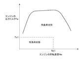
- FIG. 3 is a graph showing the relationship between the engine speed and the output torque.
- the engine system 1 of this embodiment includes a multi-cylinder engine 2, an exhaust turbine supercharger 3, a throttle valve 4, an exhaust purification catalyst 5, and an exhaust energy recovery device 6. I have.
- the engine 2 includes a cylinder block (not shown) and a cylinder head 20 that is integrally assembled to the upper part of the cylinder block.
- the engine 2 is provided with a plurality of combustion chambers 22, an intake manifold 23, a plurality of fuel injection valves 24, and a crankshaft 25.
- the intake manifold 23 has a plurality of branch portions 230 that are respectively connected to the plurality of combustion chambers 22 and a collection portion 231 in which the plurality of branch portions 230 gather.
- the collecting portion 231 is connected to the intake passage 70.
- the intake passage 70 is a passage that guides air outside the vehicle to the engine 2.
- the air supplied from the intake passage 70 to the collecting portion 231 of the intake manifold 23 is supplied to each combustion chamber 22 via the branch portion 230 of the intake manifold 23.
- the intake passage 70 is provided with the compressor wheel 30 of the supercharger 3 and the throttle valve 4 in order from the upstream side to the downstream side.
- the throttle valve 4 adjusts the flow rate of air passing through the intake passage 70, that is, the amount of intake air supplied to the engine 2 by adjusting the opening thereof.
- the plurality of fuel injection valves 24 are respectively disposed in the plurality of combustion chambers 22. Each fuel injection valve 24 injects an amount of fuel corresponding to the amount of air supplied to the combustion chamber 22 into the combustion chamber 22. When this fuel burns in the combustion chamber 22 and the engine 2 is driven, the crankshaft 25 that is the output shaft of the engine 2 rotates.
- the cylinder head 20 is provided with an exhaust manifold 26, a flow rate adjusting valve 27, and an exhaust passage 720.
- the exhaust manifold 26 has a plurality of branch portions 260 connected to the plurality of combustion chambers 22, respectively, and a collecting portion 261 in which the plurality of branch portions 260 gather.
- the collecting portion 261 communicates with an exhaust passage 710 outside the cylinder head 20 via an exhaust passage 262 in the cylinder head 20. Therefore, the exhaust discharged from each combustion chamber 22 is collected in the collecting portion 261 of the exhaust manifold 26 and then flows to the exhaust passage 710 via the exhaust passage 262.
- the turbine wheel 31 of the supercharger 3 and the exhaust purification catalyst 5 are sequentially arranged from the upstream to the downstream.
- the main exhaust passage 71 is configured by the exhaust manifold 26 and the exhaust passage 710.
- the upstream portion of the exhaust passage 720 is in communication with the collecting portion 261 of the exhaust manifold 26.
- a heat radiating portion 720a having an enlarged passage area is formed in the middle of the exhaust passage 720.
- a downstream portion of the exhaust passage 720 communicates with an exhaust passage 721 outside the cylinder head 20.
- a portion on the downstream side of the exhaust passage 721 is connected to the downstream side of the main exhaust passage 71 from the turbine wheel 31 of the supercharger 3 and to the upstream side of the exhaust purification catalyst 5. Accordingly, a part of the exhaust collected in the collecting portion 261 of the exhaust manifold 26 flows into the main exhaust passage 71 via the exhaust passage 720 and the exhaust passage 721.
- the exhaust passage 720 and the exhaust passage 721 constitute a sub exhaust passage 72 provided separately from the main exhaust passage 71.
- the main exhaust passage 71 and the sub exhaust passage 72 constitute an exhaust passage 8 that guides the exhaust discharged from the combustion chamber 22 of the engine 2 to the exhaust purification catalyst 5.
- the flow rate adjusting valve 27 is disposed in a portion of the exhaust passage 720 on the upstream side of the heat radiating portion 720a.
- the flow rate adjustment valve 27 functions as a flow rate adjustment unit that adjusts the flow rate of the exhaust gas flowing through the sub exhaust passage 72 by adjusting the opening degree.
- the flow rate adjustment valve 27 is in the fully open state, so that the sub exhaust passage 72 is in the fully open state, so that the passage volume of the exhaust passage 8 corresponds to the sum of the passage volume of the main exhaust passage 71 and the sub exhaust passage 72.
- the flow rate adjustment valve 27 When the flow rate adjustment valve 27 is in the fully closed state, the sub exhaust passage 72 is in the fully closed state, so that the passage volume of the exhaust passage 8 is a second passage volume corresponding to the passage volume of the main exhaust passage 71.
- the flow rate adjustment valve 27 corresponds to a passage volume changing unit that can change the passage volume of the exhaust passage 8 to a first passage volume and a second passage volume.
- the supercharger 3 includes a compressor wheel 30 disposed in the intake passage 70 and a turbine wheel 31 disposed in the main exhaust passage 71.
- the turbine wheel 31 rotates.
- the compressor wheel 30 rotates in conjunction with the rotation of the turbine wheel 31, the air supplied from the intake passage 70 to the combustion chamber 22 is supercharged.
- the flow rate of air supplied to the combustion chamber 22 and exhaust gas discharged from the combustion chamber 22 increases. Boost pressure rises.
- the exhaust purification catalyst 5 purifies the exhaust gas flowing through the main exhaust passage 71.
- the exhaust purification catalyst 5 has a structure in which a catalyst material is supported on a monolith carrier which is a prismatic member made of, for example, a ceramic material.
- the exhaust energy recovery device 6 is a device that recovers exhaust energy as electric energy by generating electricity using the flow of exhaust gas in the sub exhaust passage 72.
- the exhaust energy recovery device 6 includes a generator 60, a power converter 61, a battery 62, and a battery control unit 63.
- the generator 60 has a turbine 600 disposed in the exhaust passage 721.
- the turbine 600 is composed of, for example, an axial flow turbine, and rotates based on the flow of exhaust in the exhaust passage 721.
- the generator 60 generates power based on the rotation of the turbine 600.
- the electric power generated by the generator 60 is converted into DC power suitable for charging the battery 62 by the power converter 61, and then the converted DC power is charged in the battery 62.
- the electric power charged in the battery 62 is supplied to various electronic devices mounted on the vehicle.
- the battery control unit 63 controls charging and discharging of the battery 62 while constantly monitoring an SOC (state of charge) value indicating a charging state of the battery 62.
- SOC state of charge
- the SOC value is obtained by defining the fully discharged state as 0%, defining the fully charged state as 100%, and quantifying the charged state of the battery 62 in the range of 0% to 100%.
- the battery control unit 63 constantly monitors the power consumption of the battery 62 based on the discharge amount of the battery 62.
- the battery control unit 63 corresponds to a charge state detection unit that detects the charge state of the battery 62.
- the engine system 1 includes an ECU (Electronic Control Unit) 10 that performs various controls of the engine 2.
- the ECU 10 corresponds to a control unit.
- the ECU 10 is mainly configured by a microcomputer having a CPU, a ROM, a RAM, an input port, an output port, and the like.
- the CPU executes arithmetic processing related to various controls of the engine 2.
- the ROM stores programs and data necessary for various controls of the engine 2. In the RAM, CPU calculation results and the like are temporarily stored.
- the input port and the output port are for inputting and outputting signals to / from an external device.
- the air flow meter 11, the pressure sensor 12, the throttle position sensor 13, the engine rotation speed sensor 14, the temperature sensor 15, and the accelerator position sensor 16 are connected to the input port of the ECU 10.
- the air flow meter 11 detects the amount of air passing through the intake passage 70 and outputs a detection signal corresponding to the detected amount of air to the ECU 10.
- the pressure sensor 12 detects the air pressure upstream of the throttle valve 4 in the intake passage 70 and downstream of the compressor wheel 30, and outputs a detection signal corresponding to the detected air pressure to the ECU 10.
- the throttle position sensor 13 detects the throttle opening, which is the opening of the throttle valve 4, and outputs a detection signal corresponding to the detected throttle opening to the ECU 10.
- the engine rotation speed sensor 14 detects an engine rotation speed that is the rotation speed of the crankshaft 25 of the engine 2 and outputs a detection signal corresponding to the detected engine rotation speed to the ECU 10.
- the temperature sensor 15 detects the temperature of the exhaust gas flowing upstream of the exhaust purification catalyst 5 in the main exhaust passage 71 and outputs a detection signal corresponding to the detected exhaust gas temperature. Based on the detection signal of the temperature sensor 15, the temperature of the exhaust purification catalyst 5 can be estimated. That is, in the present embodiment, the temperature sensor 15 corresponds to a temperature detection unit that detects the temperature of the exhaust purification catalyst 5.
- the accelerator position sensor 16 detects an accelerator operation amount that is an operation amount of an accelerator pedal operated by a vehicle driver, and outputs a detection signal corresponding to the detected accelerator operation amount.
- the accelerator position sensor 16 corresponds to a driving state detection unit that detects the driving state of the vehicle.
- the ECU10 is connected with the battery control part 63 so that communication is possible.
- the ECU 10 can acquire information on the SOC value and power consumption of the battery 62 through communication with the battery control unit 63.
- the ECU 10 Connected to the output port of the ECU 10 are drive circuits for various devices for controlling the operation of the engine 2, such as a drive circuit for the fuel injection valve 24, a drive circuit for the throttle valve 4, and a drive circuit for the flow rate adjusting valve 27. Yes.
- the ECU 10 drives the engine 2 by controlling the fuel injection valve 24, the throttle valve 4, the flow rate adjusting valve 27, and the like based on the engine 2 and various state quantities of the vehicle obtained from the detection signals of the sensors 11 to 16. To control.
- the ECU 10 obtains the engine rotation speed Ne from the detection signal of the engine rotation speed sensor 14. Further, the ECU 10 obtains the flow rate of the air passing through the intake passage 70, in other words, the intake air amount Ga of the engine 2 based on the detection signal of the air flow meter 11. The ECU 10 obtains the output torque Te of the engine 2 based on the obtained engine rotational speed Ne and the intake air amount Ga. The ECU 10 can determine the load state of the engine 2 based on the output torque Te of the engine 2 and the engine rotational speed Ne. Thus, the ECU 10 detects the load state of the engine 2 based on the detection signals of the air flow meter 11 and the engine rotation speed sensor 14. In the present embodiment, the air flow meter 11 and the engine rotation speed sensor 14 correspond to a load state detection unit that detects the load state of the engine 2.
- the ECU 10 obtains the supercharging pressure Ps from the detection signal of the pressure sensor 12. Further, the ECU 10 obtains the throttle opening degree Ta based on the detection signal of the throttle position sensor 13. The ECU 10 controls the fuel injection valve 24, the throttle valve 4 and the like based on the state quantities of the engine 2 such as the obtained output torque Te, engine rotational speed Ne, supercharging pressure Ps, and throttle opening degree Ta.
- the ECU 10 obtains the temperature of the exhaust gas flowing into the exhaust purification catalyst 5 from the detection signal of the temperature sensor 15, and estimates the temperature Tc of the exhaust purification catalyst 5 based on the obtained exhaust gas temperature. Further, the ECU 10 determines the accelerator operation amount Pa based on the detection signal of the accelerator position sensor 16. The ECU 10 adjusts the opening of the flow rate adjustment valve 27 based on the estimated temperature Tc of the exhaust purification catalyst 5, the engine rotational speed Ne, the output torque Te of the engine 2, the accelerator operation amount Pa, the SOC value of the battery 62, and the like.
- the ECU 10 repeatedly executes the process shown in FIG. 2 at a predetermined calculation cycle.
- the ECU 10 first determines whether or not the temperature Tc of the exhaust purification catalyst 5 is lower than the activation temperature Tca in step S10. If the ECU 10 makes a positive determination in step S10, that is, if the temperature Tc of the exhaust purification catalyst 5 is lower than the activation temperature Tca, the ECU 10 fully closes the flow rate adjustment valve 27 as step S15. That is, the exhaust is prevented from flowing into the sub exhaust passage 72. As a result, all of the high-temperature exhaust gas collected in the collecting portion 261 of the exhaust manifold 26 flows through the main exhaust passage 71, so that the exhaust purification catalyst 5 easily rises to the activation temperature Tca.
- step S10 determines whether or not the engine 2 is in a high load state as step S11.
- the high load state is a state in which exhaust energy larger than the exhaust energy necessary for ensuring the activated state of the exhaust purification catalyst 5 is supplied to the exhaust purification catalyst 5, in other words, exhaust purification. This means that the supply of exhaust energy to the catalyst 5 is excessive.
- the ECU 10 has at least one of the conditions that the engine rotational speed Ne is a predetermined value Ne1 or more and that the output torque Te of the engine 2 is a predetermined value Te1 or more. When it is satisfied, it is determined that the engine 2 is in a high load state.
- the solid line shown in FIG. 3 indicates the upper limit value of the output torque Te of the engine 2 with respect to the engine rotational speed Ne.
- the ECU 10 determines that the engine 2 is in a low load state when the engine rotation speed is less than the predetermined value Ne1 and the output torque Te of the engine 2 is less than the predetermined value Te1.
- the low load state indicates a load state of the engine 2 excluding a high load state.
- Each of the predetermined values Ne1 and Te1 is set in advance through experiments or the like so as to determine whether or not the engine 2 is in a high load state, and is stored in the ROM of the ECU 10.
- step S11 if the ECU 10 makes a negative determination in step S11, that is, if the engine 2 is in a low load state, the flow rate adjustment valve 27 is fully closed as step S15. That is, the ECU 10 controls the flow rate adjustment valve 27 so that the passage volume of the exhaust passage 8 becomes the second passage volume corresponding to only the passage volume of the main exhaust passage 71.
- step S11 determines whether or not the high load state of the engine 2 continues as step S12. Specifically, when the temporal change amount of the accelerator operation amount Pa exceeds a predetermined value, the ECU 10 determines that the high load state of the engine 2 does not continue, and the accelerator operation amount Pa is determined over time. When the change amount is equal to or less than the predetermined value, it is determined that the high load state of the engine 2 continues.
- step S12 If the ECU 10 makes a negative determination in step S12, that is, if the high load state of the engine 2 does not continue, the ECU 10 fully closes the flow rate adjustment valve 27 as step S15.
- step S12 If the ECU 10 makes an affirmative determination in step S12, that is, if the high load state of the engine 2 continues, the ECU 10 fully opens the flow rate adjustment valve 27 in step S13. That is, the ECU 10 controls the flow rate adjustment valve 27 so that the passage volume of the exhaust passage 8 becomes the first passage volume corresponding to the sum of the passage volume of the main exhaust passage 71 and the passage volume of the sub exhaust passage 72. As a result, part of the exhaust collected in the collecting portion 261 of the exhaust manifold 26 flows through the sub exhaust passage 72, so that the generator 60 generates power and the power generated by the generator 60 is charged in the battery 62.
- step S14 judges whether charge of the battery 62 was completed as step S14 following step S13. Specifically, the ECU 10 determines that charging of the battery 62 is completed when the SOC value of the battery 62 is equal to or greater than a predetermined value, and determines that the battery 62 is charged when the SOC value of the battery 62 is less than the predetermined value. It is determined that charging 62 is not completed.
- step S14 determines whether or not the engine 2 is in a high load state as step S16.
- the determination process in step S16 is the same as the determination process in step S11.
- step S17 the ECU10 adjusts the opening degree of the flow regulating valve 27 according to the power consumption state of the battery 62 as step S17, when it affirmation determinates by step S16, ie, when the engine 2 is a high load state. For example, the ECU 10 determines whether or not a predetermined amount or more of power is consumed in a period from the present to a predetermined time based on the past transition of the power consumption of the battery 62 obtained by communication with the battery control unit 63. Determine whether. When it is determined that more than a predetermined amount of electric power is consumed, the ECU 10 adjusts the opening degree of the flow rate adjustment valve 27 in the opening direction as the predicted electric power consumption is larger. As a result, the larger the expected power consumption, the greater the flow rate of the exhaust gas flowing through the sub exhaust passage 72, so the power generation amount of the generator 60 can be increased. After executing step S17, the ECU 10 returns to step S14.
- step S14 the ECU 10 makes an affirmative determination in step S14, and in step S15, the flow rate adjustment valve 27 is fully closed. Further, if the ECU 10 makes a negative determination in step S16 before the charging of the battery 62 is completed, that is, if the engine 2 is not in a high load state, the ECU 10 sets the flow rate adjustment valve 27 to the fully closed state as step S15. To do.
- the flow rate adjustment valve 27 is configured such that the passage volume of the exhaust passage 8 is equal to the sum of the passage volume of the main exhaust passage 71 and the passage volume of the sub exhaust passage 72, and the passage of the main exhaust passage 71. It changes to the 2nd passage volume equivalent to only volume.
- the ECU 10 controls the flow rate adjustment valve 27 so that the exhaust passage 8 becomes the second passage volume.
- the passage volume of the exhaust passage 8 becomes the first passage volume. Compared to the set case, it becomes smaller. Therefore, since the amount of heat released from the exhaust gas in the exhaust passage 8 is reduced, the temperature of the exhaust gas flowing into the exhaust purification catalyst 5 can be raised. Therefore, the warm-up performance of the exhaust purification catalyst 5 can be improved.
- the ECU 10 When setting the exhaust passage 8 to the second passage volume, the ECU 10 sets the passage volume of the exhaust passage 8 to the minimum value by fully closing the flow rate adjustment valve 27. Thereby, since the heat radiation amount of the exhaust gas in the exhaust passage 8 can be minimized, the warm-up performance of the exhaust purification catalyst 5 can be further improved.
- the ECU 10 detects the load state of the engine 2 based on the output torque Te of the engine 2 and the engine rotation speed Ne obtained from the detection signals of the air flow meter 11 and the engine rotation speed sensor 14, respectively.
- the ECU 10 determines that the passage volume of the exhaust passage 8 is the passage of the main exhaust passage 71.
- the flow rate adjustment valve 27 is controlled so as to be an added value of the volume and the passage volume of the sub exhaust passage 72.
- the ECU 10 sets the passage volume of the exhaust passage 8 to the maximum value by opening the flow rate adjustment valve 27. Therefore, since the heat radiation amount in the exhaust passage 8 can be maximized, the excessive temperature rise of the exhaust purification catalyst 5 can be further suppressed.
- the ECU 10 When the passage volume of the exhaust passage 8 is set to the added value of the passage volume of the main exhaust passage 71 and the passage volume of the sub exhaust passage 72, the ECU 10 The flow rate adjusting valve 27 is controlled so that the passage volume of the exhaust passage 8 becomes only the passage volume of the main exhaust passage 71. Thereby, since the fall of the temperature of the exhaust gas which flows into the exhaust purification catalyst 5 can be suppressed, it becomes easy to ensure the activation state of the exhaust purification catalyst 5.
- the exhaust passage 8 includes a main exhaust passage 71 having an exhaust manifold 26 and an exhaust passage 710, and a sub exhaust passage 72.
- the flow rate adjustment valve 27 adjusts the flow rate of the exhaust gas flowing through the sub exhaust passage 72.
- the ECU 10 changes the passage volume of the exhaust passage 8 by adjusting the opening degree of the flow rate adjustment valve 27. According to such a configuration, the passage volume of the exhaust passage 8 can be easily changed.
- the sub exhaust passage 72 is formed with a heat radiating portion 720a having an enlarged passage area. Therefore, since the heat dissipation amount of the exhaust gas flowing through the sub exhaust passage 72 can be further increased, the excessive temperature rise of the exhaust purification catalyst 5 can be further suppressed.
- the sub-exhaust passage 72 is provided with an exhaust energy recovery device 6 that recovers exhaust energy as electric energy.
- the ECU 10 adjusts the opening degree of the flow rate adjustment valve 27 based on a parameter indicating the driving state of the exhaust energy recovery device 6, specifically, the SOC value and power consumption of the battery 62. Thereby, the exhaust energy recovery apparatus 6 can be driven more appropriately.
- the said embodiment can also be implemented with the following forms.
- the exhaust energy recovery device 6 disposed in the sub exhaust passage 72 is not limited to the generator 60, and any device that drives using exhaust energy can be used.
- the ECU 10 performs exhaust when the temperature Tc of the exhaust purification catalyst 5 is equal to or higher than the activation temperature Tca and the engine 2 is in a high load state regardless of whether or not the high load state of the engine 2 continues.
- the flow rate adjustment valve 27 may be controlled so that the passage volume of the passage 8 becomes an added value of the passage volume of the main exhaust passage 71 and the passage volume of the sub exhaust passage 72. Even with such a configuration, it is possible to suppress the excessive temperature rise of the exhaust purification catalyst 5.
- the generator 60 may be excluded from the sub exhaust passage 72. According to such a configuration, no pressure loss occurs when the exhaust gas flowing through the sub exhaust passage 72 passes through the generator 60. Compared with the case where only the main exhaust passage 71 is used as the exhaust passage 8, the pressure loss of the exhaust gas in the exhaust passage 8 is greater when the main exhaust passage 71 and the sub exhaust passage 72 are used as the exhaust passage 8. Can be reduced.
- the exhaust manifold 26 and the heat radiating portion 720a are connected via a part of the exhaust passage 720, but these may be spatially separated.
- the cylinder head 20 is provided with an exhaust passage for guiding the exhaust discharged from each combustion chamber 22 to the heat radiating portion 720a.
- the cylinder head 20 is provided with an opening / closing valve capable of flowing the exhaust discharged from each combustion chamber 22 to either the exhaust manifold 26 or the heat radiating portion 720a instead of the flow rate adjustment valve 27. Then, the ECU 10 controls the on-off valve so that the exhaust discharged from each combustion chamber 22 flows only to the exhaust manifold 26 as step S15 shown in FIG. Further, as step S13 shown in FIG.
- the ECU 10 controls the on-off valve so that the exhaust discharged from each combustion chamber 22 flows only to the heat dissipating part 720a. Furthermore, ECU10 adjusts the opening degree of an on-off valve as step S17.
- the passage volume of the heat radiating portion 720a is preferably larger than the passage volume of the collecting portion 261 of the exhaust manifold 26 in order to suppress an excessive temperature rise of the exhaust purification catalyst 5. .
- the positional relationship between the collecting portion 261 of the exhaust manifold 26 of the cylinder head 20 and the heat radiating portion 720a can be changed as appropriate.
- the heat radiating portion 720 a may be disposed at a position shifted in the vertical direction with respect to the collecting portion 261 of the exhaust manifold 26.
- the ECU 10 may determine whether or not the engine 2 is in a high load state based on an arbitrary state quantity of the engine 2 in steps S11 and S16 shown in FIG.
- the state quantity of the engine 2 used at this time includes the temperature of the exhaust gas flowing into the turbine wheel 31, the temperature of the exhaust gas flowing out from the turbine wheel 31, the pressure of the exhaust gas flowing into the turbine wheel 31, and the exhaust gas before and after the turbine wheel 31.
- the rotational speed of the supercharger 3, the in-cylinder pressure that is the pressure in each combustion chamber 22, the pressure in the intake manifold 23, and the like can be used.
- the appropriate sensor which can detect it is required.
- the engine system 1 may have a temperature sensor that directly detects the temperature of the exhaust purification catalyst 5 instead of the temperature sensor 15.
- the -ECU10 may determine whether the high load state of the engine 2 continues based on the arbitrary state quantity of a vehicle as step S12 shown by FIG. For example, the ECU 10 detects the speed of the vehicle with a vehicle speed sensor, and determines that the high load state of the engine 2 does not continue when the temporal change amount of the speed of the vehicle exceeds a predetermined value. When the temporal change amount of the vehicle speed is equal to or less than a predetermined value, it may be determined that the high load state of the engine 2 continues.
- the ECU 10 may set the opening of the flow rate adjustment valve 27 to an opening that is opened by a predetermined opening from the fully closed state in step S15 shown in FIG. Further, in step S13 shown in FIG. 2, the ECU 10 may set the opening degree of the flow rate adjustment valve 27 to an opening degree that is closed by a predetermined opening degree from the fully opened state.
- the means and / or function provided by the ECU 10 can be provided by software stored in a substantial ROM and a computer that executes the software, only software, only hardware, or a combination thereof.
- the ECU 10 when the ECU 10 is provided by an electronic circuit which is hardware, it can be provided by a digital circuit including a large number of logic circuits or an analog circuit.
Landscapes
- Engineering & Computer Science (AREA)
- Chemical & Material Sciences (AREA)
- Combustion & Propulsion (AREA)
- Mechanical Engineering (AREA)
- General Engineering & Computer Science (AREA)
- Chemical Kinetics & Catalysis (AREA)
- Health & Medical Sciences (AREA)
- Toxicology (AREA)
- Exhaust Gas After Treatment (AREA)
- Combined Controls Of Internal Combustion Engines (AREA)
- Exhaust Silencers (AREA)
Abstract
車両のエンジンシステム(1)は、排気通路(8)と、通路容積変更部(27)と、温度検出部(15)と、制御部(10)とを備える。排気通路には、排気浄化触媒(5)が配置されている。通路容積変更部は、排気通路の通路容積を第1通路容積、及び第1通路容積よりも小さい第2通路容積に変更できる。温度検出部は、排気浄化触媒の温度を検出する。制御部は、排気浄化触媒の温度が活性化温度未満である場合には、排気通路の通路容積が第2通路容積となるように通路容積変更部を制御し、排気浄化触媒の温度が活性化温度以上であって、且つエンジン(2)が高負荷状態である場合には、排気通路の通路容積が第1通路容積となるように通路容積変更部を制御する。
Description
本出願は、2016年5月13日に出願された日本国特許出願2016-096827号に基づくものであって、その優先権の利益を主張するものであり、その特許出願の全ての内容が、参照により本明細書に組み込まれる。
本開示は、車両のエンジンシステムに関する。
従来、特許文献1に記載の車両のエンジンシステムがある。特許文献1に記載のエンジンシステムは、触媒と、排気熱回収装置を備えている。触媒は、エンジンの排気管の途中に配置されており、エンジンの排気を浄化する。排気熱回収装置は、排気管の触媒よりも排気流れの上流側に配置されている。排気熱回収装置は、蒸発部と、凝縮部と、戻し通路と、弁機構と、制御部とを備えている。蒸発部は、排気の熱により内部の作動媒体を蒸発させる。凝縮部は、蒸発部から流入する作動媒体の熱をエンジンの冷却水に放熱して作動媒体を凝縮させる。戻し通路は、凝縮部において凝縮された作動媒体を蒸発部に戻す。弁機構は、戻し通路に設けられ、戻し通路の通路面積を調整する。制御部は、エンジンの運転状態に応じて弁機構の開度を調整する。
特許文献1に記載のエンジンシステムでは、排気管における触媒よりも排気流れ上流側に排気熱回収装置が配置されているため、排気熱回収装置が設けられていないエンジンシステムと比較すると、触媒よりも排気流れ上流側における熱容量が大きくなる。そのため、特許文献1に記載のエンジンシステムでは、排気熱回収装置の設けられていないエンジンシステムと比較すると、触媒に流入する排気の温度が低くなり易い。これが、エンジンの冷間始動時等、エンジンの低負荷時において触媒の暖機性能を低下させる要因となっている。
本開示の目的は、排気浄化触媒の暖機性能を向上させるとともに、排気浄化触媒の過昇温を抑制することのできる車両のエンジンシステムを提供することにある。
本開示の一態様による車両のエンジンシステムは、排気通路と、通路容積変更部と、温度検出部と、制御部とを備える。排気通路には、エンジンの燃焼室から排出される排気が流れるとともに、排気浄化触媒が配置されている。通路容積変更部は、排気通路の通路容積を第1通路容積、及び第1通路容積よりも小さい第2通路容積に変更できる。温度検出部は、排気浄化触媒の温度を検出する。制御部は、通路容積変更部を制御する。制御部は、排気浄化触媒の温度が活性化温度未満である場合には、排気通路の通路容積が第2通路容積となるように通路容積変更部を制御し、排気浄化触媒の温度が活性化温度以上であって、且つエンジンが高負荷状態である場合には、排気通路の通路容積が第1通路容積となるように通路容積変更部を制御する。
この構成によれば、エンジンの冷間始動時等において排気浄化触媒の温度が活性化温度未満となっている状況では、排気通路の通路容積が第2通路容積となる。すなわち、排気通路の通路容積が、第1通路容積に設定されている場合と比較すると、小さくなる。これにより、排気通路における排気の放熱量が減少するため、排気浄化触媒に流入する排気の温度が上昇する。よって、排気浄化触媒の暖機性能を向上させることができる。
また、排気浄化触媒の温度が活性化温度以上であって、且つエンジンが高負荷状態である場合には、排気通路の通路容積が第1通路容積となる。すなわち、排気通路の通路容積が、第2通路容積に設定されている場合と比較すると、大きくなる。これにより、排気通路における排気の放熱量を増加させることができる。結果的に、排気浄化触媒に流入する排気の温度を低下させることができるため、排気浄化触媒の過昇温を抑制することができる。
以下、エンジンシステムの一実施形態について説明する。
図1に示されるように、本実施形態のエンジンシステム1は、多気筒エンジン2と、排気タービン式過給機3と、スロットルバルブ4と、排気浄化触媒5と、排気エネルギ回収装置6とを備えている。
図1に示されるように、本実施形態のエンジンシステム1は、多気筒エンジン2と、排気タービン式過給機3と、スロットルバルブ4と、排気浄化触媒5と、排気エネルギ回収装置6とを備えている。
エンジン2は、図示しないシリンダブロックと、シリンダブロックの上部に一体的に組み付けられたシリンダヘッド20とを備えている。エンジン2には、複数の燃焼室22と、吸気マニホールド23と、複数の燃料噴射弁24と、クランクシャフト25とが設けられている。
吸気マニホールド23は、複数の燃焼室22にそれぞれ接続される複数の分岐部230と、複数の分岐部230が集合する集合部231とを有している。集合部231は、吸気通路70に接続されている。吸気通路70は、車両外部の空気をエンジン2に導く通路である。吸気通路70から吸気マニホールド23の集合部231に供給された空気は、吸気マニホールド23の分岐部230を介して各燃焼室22に供給される。吸気通路70には、その上流から下流に向かって過給機3のコンプレッサホイール30、及びスロットルバルブ4が順に設けられている。スロットルバルブ4は、その開度の調整により、吸気通路70を通過する空気の流量、すなわちエンジン2に供給される吸入空気量を調整する。
複数の燃料噴射弁24は、複数の燃焼室22にそれぞれ配置されている。各燃料噴射弁24は、燃焼室22に供給される空気の量に対応した量の燃料を燃焼室22内に噴射する。この燃料が燃焼室22内で燃焼してエンジン2が駆動することにより、エンジン2の出力軸であるクランクシャフト25が回転する。
シリンダヘッド20には、排気マニホールド26と、流量調整弁27と、排気通路720とが設けられている。
排気マニホールド26は、複数の燃焼室22にそれぞれ接続される複数の分岐部260と、複数の分岐部260が集合する集合部261とを有している。集合部261は、シリンダヘッド20内の排気通路262を介してシリンダヘッド20の外部の排気通路710に連通されている。よって、各燃焼室22から排出される排気は排気マニホールド26の集合部261に集められた後、排気通路262を介して排気通路710へと流れる。排気通路710には、その上流から下流に向かって順に過給機3のタービンホイール31、及び排気浄化触媒5が順に配置されている。本実施形態では、排気マニホールド26、及び排気通路710によりメイン排気通路71が構成されている。
排気通路720の上流側の部分は、排気マニホールド26の集合部261に連通されている。排気通路720の途中には、その通路面積が拡大された放熱部720aが形成されている。排気通路720の下流側の部分は、シリンダヘッド20の外部の排気通路721に連通されている。排気通路721の下流側の部分は、メイン排気通路71における過給機3のタービンホイール31よりも下流側であって、且つ排気浄化触媒5よりも上流側に接続されている。よって、排気マニホールド26の集合部261に集められた排気の一部は、排気通路720及び排気通路721を介してメイン排気通路71へと流入する。本実施形態では、排気通路720及び排気通路721により、メイン排気通路71とは別に設けられるサブ排気通路72が構成されている。また、メイン排気通路71及びサブ排気通路72により、エンジン2の燃焼室22から排出される排気を排気浄化触媒5に導く排気通路8が構成されている。
流量調整弁27は、排気通路720における放熱部720aよりも上流側の部分に配置されている。流量調整弁27は、その開度の調整により、サブ排気通路72を流れる排気の流量を調整する流量調整部として機能する。流量調整弁27が全開状態である場合、サブ排気通路72は全開状態となるため、排気通路8の通路容積は、メイン排気通路71の通路容積とサブ排気通路72との加算値に相当する第1通路容積となる。流量調整弁27が全閉状態である場合、サブ排気通路72は全閉状態となるため、排気通路8の通路容積は、メイン排気通路71の通路容積に相当する第2通路容積となる。本実施形態では、流量調整弁27が、排気通路8の通路容積を第1通路容積及び第2通路容積に変更可能な通路容積変更部に相当する。
過給機3は、吸気通路70に配置されるコンプレッサホイール30と、メイン排気通路71に配置されるタービンホイール31とを備えている。過給機3では、メイン排気通路71を流れる排気がタービンホイール31を通過すると、タービンホイール31が回転する。このタービンホイール31の回転に併せてコンプレッサホイール30が回転することにより、吸気通路70から燃焼室22に供給される空気が過給される。このような過給機3により空気が過給されるエンジン2では、エンジン2の回転速度の上昇に伴い燃焼室22に供給される空気及び燃焼室22から排出される排気の流量が多くなるほど、過給圧が上昇する。
排気浄化触媒5は、メイン排気通路71を流れる排気を浄化する。排気浄化触媒5は、例えばセラミック材からなる角柱状の部材であるモノリス担体に触媒物質が担持された構造からなる。
排気エネルギ回収装置6は、サブ排気通路72の排気の流れを利用して発電することにより、排気エネルギを電気エネルギとして回収する装置である。排気エネルギ回収装置6は、発電機60と、電力変換器61と、バッテリ62と、バッテリ制御部63とを有している。
発電機60は、排気通路721に配置されるタービン600を有している。タービン600は、例えば軸流式のタービンからなり、排気通路721の排気の流れに基づいて回転する。このタービン600の回転に基づいて発電機60が発電する。発電機60により発電された電力は、電力変換器61によりバッテリ62の充電に適した直流電力に変換された後、この変換された直流電力がバッテリ62に充電される。バッテリ62に充電された電力は、車両に搭載された各種電子機器に供給される。
バッテリ制御部63は、バッテリ62の充電状態を示すSOC(state of charge)値を常時監視しつつ、バッテリ62の充電及び放電を制御する。SOC値は、完全放電状態を0%と定義し、満充電状態を100%と定義した上で、バッテリ62の充電状態を0%から100%の範囲で数値化したものである。バッテリ制御部63は、バッテリ62の放電量に基づいて、バッテリ62の電力消費量を常時監視している。本実施形態では、バッテリ制御部63が、バッテリ62の充電状態を検出する充電状態検出部に相当する。
エンジンシステム1は、エンジン2の各種制御を行うECU(Electronic Control Unit)10を備えている。本実施形態では、ECU10が制御部に相当する。ECU10は、CPUやROM、RAM、入力ポート、及び出力ポート等を有するマイクロコンピュータを中心に構成されている。CPUは、エンジン2の各種制御に係る演算処理を実行する。ROMには、エンジン2の各種制御に必要なプログラムやデータが記憶されている。RAMには、CPUの演算結果等が一時的に記憶される。入力ポート及び出力ポートは、外部機器との間で信号を入力及び出力するためのものである。
ECU10の入力ポートには、エアフロメータ11、圧力センサ12、スロットルポジションセンサ13、エンジン回転速度センサ14、温度センサ15、及びアクセルポジションセンサ16が接続されている。
エアフロメータ11は、吸気通路70を通過する空気の量を検出するとともに、検出された空気の量に応じた検出信号をECU10に出力する。
圧力センサ12は、吸気通路70におけるスロットルバルブ4の上流側であって、且つコンプレッサホイール30の下流側の空気圧を検出するとともに、検出された空気圧に応じた検出信号をECU10に出力する。
スロットルポジションセンサ13は、スロットルバルブ4の開度であるスロットル開度を検出するとともに、検出されたスロットル開度に応じた検出信号をECU10に出力する。
エンジン回転速度センサ14は、エンジン2のクランクシャフト25の回転速度であるエンジン回転速度を検出するとともに、検出されたエンジン回転速度に応じた検出信号をECU10に出力する。
温度センサ15は、メイン排気通路71における排気浄化触媒5の上流側を流れる排気の温度を検出するとともに、検出された排気の温度に応じた検出信号を出力する。この温度センサ15の検出信号に基づいて、排気浄化触媒5の温度を推定することができる。すなわち、本実施形態では、温度センサ15が、排気浄化触媒5の温度を検出する温度検出部に相当する。
アクセルポジションセンサ16は、車両の運転者によって操作されるアクセルペダルの操作量であるアクセル操作量を検出するとともに、検出されたアクセル操作量に応じた検出信号を出力する。本実施形態では、アクセルポジションセンサ16が、車両の運転状態を検出する運転状態検出部に相当する。
ECU10は、バッテリ制御部63と通信可能に接続されている。ECU10は、バッテリ制御部63との通信により、バッテリ62のSOC値や電力消費量の情報を取得することが可能である。
ECU10の出力ポートには、燃料噴射弁24の駆動回路、スロットルバルブ4の駆動回路、及び流量調整弁27の駆動回路等、エンジン2の運転を制御するための各種機器の駆動回路が接続されている。ECU10は、各センサ11~16の検出信号から求められるエンジン2及び車両の各種状態量等に基づいて燃料噴射弁24やスロットルバルブ4、流量調整弁27等を制御することにより、エンジン2の駆動を制御する。
例えばECU10は、エンジン回転速度センサ14の検出信号からエンジン回転速度Neを求める。また、ECU10は、エアフロメータ11の検出信号に基づいて、吸気通路70を通過する空気の流量、換言すればエンジン2の吸入空気量Gaを求める。ECU10は、求められたエンジン回転速度Ne及び吸入空気量Gaに基づいてエンジン2の出力トルクTeを求める。ECU10は、このエンジン2の出力トルクTeとエンジン回転速度Neに基づいてエンジン2の負荷状態を判断することができる。このように、ECU10は、エアフロメータ11及びエンジン回転速度センサ14のそれぞれの検出信号に基づいてエンジン2の負荷状態を検出する。本実施形態では、エアフロメータ11及びエンジン回転速度センサ14がエンジン2の負荷状態を検出する負荷状態検出部に相当する。
また、ECU10は、圧力センサ12の検出信号から過給圧Psを求める。さらに、ECU10は、スロットルポジションセンサ13の検出信号に基づいてスロットル開度Taを求める。ECU10は、求められた出力トルクTeやエンジン回転速度Ne、過給圧Ps、スロットル開度Taといったエンジン2の状態量に基づいて燃料噴射弁24やスロットルバルブ4等を制御する。
さらに、ECU10は、温度センサ15の検出信号から排気浄化触媒5に流入する排気の温度を求めるとともに、求められた排気の温度に基づいて排気浄化触媒5の温度Tcを推定する。また、ECU10は、アクセルポジションセンサ16の検出信号に基づいてアクセル操作量Paを求める。ECU10は、排気浄化触媒5の推定温度Tc、エンジン回転速度Ne、エンジン2の出力トルクTe、アクセル操作量Pa、及びバッテリ62のSOC値等に基づいて流量調整弁27の開度を調整する。
次に、図2を参照して、ECU10により実行される流量調整弁27の開度を調整する処理の手順について説明する。なお、ECU10は、図2に示される処理を所定の演算周期で繰り返し実行する。
図2に示されるように、ECU10は、まず、ステップS10として、排気浄化触媒5の温度Tcが活性化温度Tca未満であるか否かを判断する。ECU10は、ステップS10で肯定判断した場合、すなわち排気浄化触媒5の温度Tcが活性化温度Tca未満である場合には、ステップS15として、流量調整弁27を全閉状態にする。すなわち、サブ排気通路72に排気が流れないようにする。これにより、排気マニホールド26の集合部261に集められる高温の排気の全てがメイン排気通路71を流れるため、排気浄化触媒5が活性化温度Tcaまで上昇し易くなる。
一方、ECU10は、ステップS10で否定判断した場合、すなわち排気浄化触媒5の温度Tcが活性化温度Tca以上である場合には、ステップS11として、エンジン2が高負荷状態であるか否かを判定する。なお、ここでの高負荷状態とは、排気浄化触媒5の活性化状態を担保するために必要な排気エネルギよりも大きい排気エネルギが排気浄化触媒5に供給されている状態、換言すれば排気浄化触媒5への排気エネルギの供給が過剰な状態を意味する。
具体的には、図3に示されるように、ECU10は、エンジン回転速度Neが所定値Ne1以上であること、及びエンジン2の出力トルクTeが所定値Te1以上であることの少なくとも一方の条件が満たされた場合には、エンジン2が高負荷状態であると判定する。なお、図3に示される実線は、エンジン回転速度Neに対するエンジン2の出力トルクTeの上限値を示したものである。また、ECU10は、エンジン回転速度が所定値Ne1未満であって、且つエンジン2の出力トルクTeが所定値Te1未満である場合には、エンジン2が低負荷状態であると判定する。ここでの低負荷状態とは、高負荷状態を除くエンジン2の負荷状態を示す。所定値Ne1,Te1のそれぞれの値は、エンジン2が高負荷状態であるか否かを判定することができるように予め実験等を通じて設定されており、ECU10のROMに記憶されている。
図2に示されるように、ECU10は、ステップS11で否定判断した場合、すなわちエンジン2が低負荷状態である場合には、ステップS15として、流量調整弁27を全閉状態にする。すなわち、ECU10は、排気通路8の通路容積が、メイン排気通路71の通路容積のみに相当する第2通路容積となるように流量調整弁27を制御する。
ECU10は、ステップS11で肯定判断した場合、すなわちエンジン2が高負荷状態である場合には、ステップS12として、エンジン2の高負荷状態が継続するか否かを判定する。具体的には、ECU10は、アクセル操作量Paの時間的な変化量が所定値を超えている場合には、エンジン2の高負荷状態が継続しないと判定し、アクセル操作量Paの時間的な変化量が所定値以下である場合には、エンジン2の高負荷状態が継続すると判定する。
ECU10は、ステップS12で否定判定した場合、すなわちエンジン2の高負荷状態が継続しない場合には、ステップS15として、流量調整弁27を全閉状態にする。
ECU10は、ステップS12で肯定判定した場合、すなわちエンジン2の高負荷状態が継続する場合には、ステップS13として、流量調整弁27を全開状態にする。すなわち、ECU10は、排気通路8の通路容積が、メイン排気通路71の通路容積及びサブ排気通路72の通路容積の加算値に相当する第1通路容積となるように流量調整弁27を制御する。これにより、排気マニホールド26の集合部261に集められる排気の一部がサブ排気通路72を流れるため、発電機60が発電するとともに、発電機60により発電された電力がバッテリ62に充電される。
ECU10は、ステップS13に続くステップS14として、バッテリ62の充電が完了したか否かを判断する。具体的には、ECU10は、バッテリ62のSOC値が所定値以上である場合には、バッテリ62の充電が完了したと判断し、バッテリ62のSOC値が所定値未満である場合には、バッテリ62の充電が完了していないと判断する。
ECU10は、ステップS14で否定判断した場合には、ステップS16として、エンジン2が高負荷状態であるか否かを判定する。このステップS16の判定処理は、ステップS11の判定処理と同一である。
ECU10は、ステップS16で肯定判定した場合、すなわちエンジン2が高負荷状態である場合には、ステップS17として、バッテリ62の電力消費状態に応じて流量調整弁27の開度を調整する。例えば、ECU10は、バッテリ制御部63との通信により得られるバッテリ62の電力消費量の過去の推移に基づいて、現在から所定時間経過後までの期間に所定量以上の電力が消費されるか否かを判断する。ECU10は、所定量以上の電力が消費されると判断される場合には、その予想される電力消費量が大きいほど、流量調整弁27の開度を開の方向に調整する。これにより、予想される電力消費量が大きいほど、サブ排気通路72を流れる排気の流量が増加するため、発電機60の発電量を増加させることができる。ECU10は、ステップS17を実行した後、ステップS14に戻る。
その後、バッテリ62の充電が完了すると、ECU10は、ステップS14で肯定判定し、ステップS15として、流量調整弁27を全閉状態にする。また、ECU10は、バッテリ62の充電が完了する前に、ステップS16で否定判定した場合、すなわちエンジン2が高負荷状態でなくなった場合には、ステップS15として、流量調整弁27を全閉状態にする。
以上説明した本実施形態の車両のエンジンシステム1によれば、以下の(1)~(8)に示される作用及び効果を得ることができる。
(1)流量調整弁27は、排気通路8の通路容積を、メイン排気通路71の通路容積及びサブ排気通路72の通路容積の加算値に相当する第1通路容積と、メイン排気通路71の通路容積のみに相当する第2通路容積とに変更する。ECU10は、排気浄化触媒5の温度Tcが活性化温度Tca未満である場合には、排気通路8が第2通路容積となるように流量調整弁27を制御する。これにより、エンジン2の冷間始動時や低負荷運転時等において排気浄化触媒5の温度Tcが活性化温度Tca未満となっている状況では、排気通路8の通路容積が、第1通路容積に設定されている場合と比較すると、小さくなる。したがって、排気通路8における排気の放熱量が減少するため、排気浄化触媒5に流入する排気の温度を上昇させることができる。よって、排気浄化触媒5の暖機性能を向上させることができる。
(2)ECU10は、排気通路8を第2通路容積に設定する際、流量調整弁27を全閉状態にすることにより、排気通路8の通路容積を最小値に設定する。これにより、排気通路8における排気の放熱量を最小にすることができるため、排気浄化触媒5の暖機性能を更に向上させることができる。
(3)ECU10は、エアフロメータ11及びエンジン回転速度センサ14のそれぞれの検出信号から求められるエンジン2の出力トルクTe及びエンジン回転速度Neに基づいてエンジン2の負荷状態を検出する。ECU10は、排気浄化触媒5の温度Tcが活性化温度Tca以上であって、且つエンジン2の高負荷状態が継続すると判断される場合には、排気通路8の通路容積がメイン排気通路71の通路容積及びサブ排気通路72の通路容積の加算値となるように流量調整弁27を制御する。これにより、エンジン2が高負荷状態である場合には、排気通路8の通路容積が大きくなるため、排気通路8における排気の放熱量を増加させることができる。結果的に、排気浄化触媒5に流入する排気の温度を低下させることができるため、排気浄化触媒5の過昇温を抑制することができる。また、車両の加速時等の過渡運転時にエンジン2が高負荷状態になると、排気通路8の通路容積が大きくなるため、適切な排気の流れを確保し易くなる。これにより、エンジン2の出力の低下を抑制することができるため、車両のレスポンスを向上させることができる。
(4)ECU10は、排気通路8を第1通路容積に設定する際、流量調整弁27を全開状態にすることにより、排気通路8の通路容積を最大値に設定する。これにより、排気通路8における放熱量を最大にすることができるため、排気浄化触媒5の過昇温を更に抑制することができる。
(5)ECU10は、排気通路8の通路容積がメイン排気通路71の通路容積及びサブ排気通路72の通路容積の加算値に設定されている際、エンジン2が高負荷状態でなくなった場合には、排気通路8の通路容積がメイン排気通路71の通路容積のみとなるように流量調整弁27を制御する。これにより、排気浄化触媒5に流入する排気の温度の低下を抑制することができるため、排気浄化触媒5の活性化状態を担保し易くなる。
(6)排気通路8には、排気マニホールド26及び排気通路710を有するメイン排気通路71と、サブ排気通路72とが含まれている。流量調整弁27は、サブ排気通路72を流れる排気の流量を調整する。ECU10は、流量調整弁27の開度の調整により排気通路8の通路容積を変更する。このような構成によれば、排気通路8の通路容積を容易に変更することができる。
(7)サブ排気通路72には、その通路面積が拡大された放熱部720aが形成されている。これにより、サブ排気通路72を流れる排気の放熱量を更に増加させることができるため、排気浄化触媒5の過昇温を更に抑制することができる。
(8)サブ排気通路72には、排気エネルギを電気エネルギとして回収する排気エネルギ回収装置6が配置されている。ECU10は、排気エネルギ回収装置6の駆動状態を示すパラメータ、具体的にはバッテリ62のSOC値及び電力消費量に基づいて流量調整弁27の開度を調整する。これにより、排気エネルギ回収装置6をより適切に駆動させることができる。
なお、上記実施形態は、以下の形態にて実施することもできる。
なお、上記実施形態は、以下の形態にて実施することもできる。
・サブ排気通路72に配置される排気エネルギ回収装置6としては、発電機60に限らず、排気エネルギを利用して駆動する任意の装置を用いることができる。
・ECU10は、エンジン2の高負荷状態が継続するか否かに関わらず、排気浄化触媒5の温度Tcが活性化温度Tca以上であって、且つエンジン2が高負荷状態である場合に、排気通路8の通路容積がメイン排気通路71の通路容積及びサブ排気通路72の通路容積の加算値となるように流量調整弁27を制御してもよい。このような構成であっても、排気浄化触媒5の過昇温を抑制することは可能である。
・サブ排気通路72から発電機60を排除してもよい。このような構成によれば、サブ排気通路72を流れる排気が発電機60を通過する際の圧力損失が発生しなくなる。また、排気通路8としてメイン排気通路71のみを用いている場合と比較すると、排気通路8としてメイン排気通路71及びサブ排気通路72を用いている場合の方が、排気通路8における排気の圧力損失を低減することが可能となる。
・上記実施形態のシリンダヘッド20では、排気マニホールド26と放熱部720aとが排気通路720の一部を介して繋がっていたが、これらが空間的に隔てられていてもよい。この場合、シリンダヘッド20には、各燃焼室22から排出される排気を放熱部720aに導く排気通路を設ける。また、シリンダヘッド20には、流量調整弁27に代えて、各燃焼室22から排出される排気を排気マニホールド26及び放熱部720aのいずれか一方に流すことの可能な開閉弁を設ける。そして、ECU10は、図2に示されるステップS15として、各燃焼室22から排出される排気を排気マニホールド26のみに流すように開閉弁を制御する。また、ECU10は、図2に示されるステップS13として、各燃焼室22から排出される排気を放熱部720aのみに流すように開閉弁を制御する。さらに、ECU10は、ステップS17として、開閉弁の開度を調整する。なお、この構成を用いる場合には、排気浄化触媒5の過昇温を抑制するために、排気マニホールド26の集合部261の通路容積よりも、放熱部720aの通路容積の方が大きいことが好ましい。
・シリンダヘッド20の排気マニホールド26の集合部261と放熱部720aとの位置関係は適宜変更可能である。例えば、燃焼室22内でピストンが往復動する方向を上下方向とするとき、放熱部720aは、排気マニホールド26の集合部261に対して上下方向にずれた位置に配置されていてもよい。
・ECU10は、図2に示されるステップS11,S16において、エンジン2の任意の状態量に基づいてエンジン2が高負荷状態であるか否かを判断してもよい。この際に用いられるエンジン2の状態量としては、タービンホイール31に流入する排気の温度、タービンホイール31から流出する排気の温度、タービンホイール31に流入する排気の圧力、タービンホイール31の前後の排気の圧力差、過給機3の回転速度、各燃焼室22内の圧力である筒内圧力、吸気マニホールド23内の圧力等を用いることができる。なお、これらのエンジン2の状態量を用いる場合には、それを検出することの可能な適宜のセンサが必要であることは言うまでもない。
・エンジンシステム1は、温度センサ15に代えて、排気浄化触媒5の温度を直接検出する温度センサを有するものであってもよい。
・ECU10は、図2に示されるステップS12として、車両の任意の状態量に基づいて、エンジン2の高負荷状態が継続するか否かを判定してもよい。例えば、ECU10は、車速センサにより車両の速度を検出するとともに、この車両の速度の時間的な変化量が所定値を超えている場合には、エンジン2の高負荷状態が継続しないと判定し、車両の速度の時間的な変化量が所定値以下である場合には、エンジン2の高負荷状態が継続すると判定してもよい。
・ECU10は、図2に示されるステップS15において、流量調整弁27の開度を全閉状態から所定開度だけ開いた開度に設定してもよい。また、ECU10は、図2に示されるステップS13において、流量調整弁27の開度を全開状態から所定開度だけ閉じた開度に設定してもよい。
・ECU10が提供する手段及び/又は機能は、実体的なROMに記憶されたソフトウェア及びそれを実行するコンピュータ、ソフトウェアのみ、ハードウェアのみ、あるいはそれらの組み合わせにより提供することができる。例えばECU10がハードウェアである電子回路により提供される場合、それは多数の論理回路を含むデジタル回路、またはアナログ回路により提供することができる。
・本開示はこれらの具体例に限定されるものではない。これら具体例に、当業者が適宜設計変更を加えたものも、本開示の特徴を備えている限り、本開示の範囲に包含される。前述した各具体例が備える各要素およびその配置、条件、形状などは、例示したものに限定されるわけではなく適宜変更することができる。前述した各具体例が備える各要素は、技術的な矛盾が生じない限り、適宜組み合わせを変えることができる。
Claims (9)
- エンジン(2)の燃焼室(22)から排出される排気が流れるとともに、排気浄化触媒(5)が配置される排気通路(8)と、
前記排気通路の通路容積を第1通路容積、及び前記第1通路容積よりも小さい第2通路容積に変更可能な通路容積変更部(27)と、
前記排気浄化触媒の温度を検出する温度検出部(15)と、
前記エンジンの負荷状態を検出する負荷状態検出部(11,14)と、
前記通路容積変更部を制御する制御部(10)と、を備え、
前記制御部は、
前記排気浄化触媒の温度が活性化温度未満である場合には、前記排気通路の通路容積が前記第2通路容積となるように前記通路容積変更部を制御し、
前記排気浄化触媒の温度が活性化温度以上であって、且つ前記エンジンが高負荷状態である場合には、前記排気通路の通路容積が前記第1通路容積となるように前記通路容積変更部を制御する
車両のエンジンシステム。 - 車両の運転状態を検出する運転状態検出部(16)を更に備え、
前記制御部は、
前記車両の運転状態に基づいて、前記エンジンの高負荷状態が継続されるか否かを判断し、
前記排気浄化触媒の温度が活性化温度以上であって、且つ前記エンジンの高負荷状態が継続されると判断される場合には、前記排気通路の通路容積が前記第1通路容積となるように前記通路容積変更部を制御する
請求項1に記載の車両のエンジンシステム。 - 前記制御部は、
前記排気通路の通路容積が前記第1通路容積に設定されている際、前記エンジンが高負荷状態でなくなった場合には、前記排気通路の通路容積が前記第2通路容積となるように前記通路容積変更部を制御する
請求項1又は2に記載の車両のエンジンシステム。 - 前記第1通路容積は、前記排気通路の通路容積の最大値である
請求項1~3のいずれか一項に記載の車両のエンジンシステム。 - 前記第2通路容積は、前記排気通路の通路容積の最小値である
請求項1~4のいずれか一項に記載の車両のエンジンシステム。 - 前記排気通路には、
前記排気浄化触媒が配置されるメイン排気通路(71)と、
前記メイン排気通路とは別に設けられ、前記燃焼室から排出される排気を前記メイン排気通路における前記排気浄化触媒よりも上流側の部分に導くサブ排気通路(72)と、が含まれ、
前記通路容積変更部は、
前記サブ排気通路を流れる排気の流量を調整する流量調整部(27)からなり、
前記制御部は、
前記流量調整部により前記排気通路の通路容積を前記第1通路容積及び前記第2通路容積に変更する
請求項1~5のいずれか一項に記載の車両のエンジンシステム。 - 前記サブ排気通路には、その通路面積が拡大された放熱部(270a)が形成されている
請求項6に記載の車両のエンジンシステム。 - 前記サブ排気通路に配置される排気エネルギ回収装置(6)を更に備え、
前記制御部は、
前記排気エネルギ回収装置の駆動状態を示すパラメータに基づいて、前記流量調整部により前記サブ排気通路を流れる排気の流量を調整する
請求項6又は7に記載の車両のエンジンシステム。 - 前記排気エネルギ回収装置は、
前記サブ排気通路の排気の流れに基づいて発電する発電機(60)と、
前記発電機により発電された電力を充電するバッテリ(62)と、
前記バッテリの充電状態を検出する充電状態検出部(63)と、を有し、
前記制御部は、
前記バッテリの充電状態に基づいて、前記流量調整部により前記サブ排気通路を流れる排気の流量を調整する
請求項8に記載の車両のエンジンシステム。
Applications Claiming Priority (2)
| Application Number | Priority Date | Filing Date | Title |
|---|---|---|---|
| JP2016096827A JP2017203439A (ja) | 2016-05-13 | 2016-05-13 | 車両のエンジンシステム |
| JP2016-096827 | 2016-05-13 |
Publications (1)
| Publication Number | Publication Date |
|---|---|
| WO2017195515A1 true WO2017195515A1 (ja) | 2017-11-16 |
Family
ID=60267084
Family Applications (1)
| Application Number | Title | Priority Date | Filing Date |
|---|---|---|---|
| PCT/JP2017/014573 Ceased WO2017195515A1 (ja) | 2016-05-13 | 2017-04-07 | 車両のエンジンシステム |
Country Status (2)
| Country | Link |
|---|---|
| JP (1) | JP2017203439A (ja) |
| WO (1) | WO2017195515A1 (ja) |
Families Citing this family (1)
| Publication number | Priority date | Publication date | Assignee | Title |
|---|---|---|---|---|
| KR102466050B1 (ko) * | 2018-02-21 | 2022-11-14 | 현대자동차주식회사 | 차량 및 그 제어방법 |
Citations (4)
| Publication number | Priority date | Publication date | Assignee | Title |
|---|---|---|---|---|
| JP2001336417A (ja) * | 2000-05-24 | 2001-12-07 | Denso Corp | 排気装置 |
| JP2004011512A (ja) * | 2002-06-06 | 2004-01-15 | Sango Co Ltd | エンジンの排熱回収装置 |
| JP2015086794A (ja) * | 2013-10-31 | 2015-05-07 | 富士重工業株式会社 | エンジンの排気熱回収装置 |
| JP2016509970A (ja) * | 2013-02-15 | 2016-04-04 | ウォン,アレクサンダー | ターボ充電装置 |
Family Cites Families (2)
| Publication number | Priority date | Publication date | Assignee | Title |
|---|---|---|---|---|
| JPH09217642A (ja) * | 1996-02-13 | 1997-08-19 | Denso Corp | 内燃機関の制御装置 |
| JP3552489B2 (ja) * | 1997-09-25 | 2004-08-11 | トヨタ自動車株式会社 | 内燃機関の排気浄化装置 |
-
2016
- 2016-05-13 JP JP2016096827A patent/JP2017203439A/ja active Pending
-
2017
- 2017-04-07 WO PCT/JP2017/014573 patent/WO2017195515A1/ja not_active Ceased
Patent Citations (4)
| Publication number | Priority date | Publication date | Assignee | Title |
|---|---|---|---|---|
| JP2001336417A (ja) * | 2000-05-24 | 2001-12-07 | Denso Corp | 排気装置 |
| JP2004011512A (ja) * | 2002-06-06 | 2004-01-15 | Sango Co Ltd | エンジンの排熱回収装置 |
| JP2016509970A (ja) * | 2013-02-15 | 2016-04-04 | ウォン,アレクサンダー | ターボ充電装置 |
| JP2015086794A (ja) * | 2013-10-31 | 2015-05-07 | 富士重工業株式会社 | エンジンの排気熱回収装置 |
Also Published As
| Publication number | Publication date |
|---|---|
| JP2017203439A (ja) | 2017-11-16 |
Similar Documents
| Publication | Publication Date | Title |
|---|---|---|
| CN106246393B (zh) | 内燃机的控制装置 | |
| EP2366879B1 (en) | Control method of internal combustion engine | |
| US8096123B2 (en) | System and method for mode transition for a two-stage series sequential turbocharger | |
| JP5982203B2 (ja) | 内燃機関の制御装置 | |
| JP5170339B2 (ja) | 過給機付き内燃機関の制御装置 | |
| JP2010164045A (ja) | 過給式エンジンの吸気量制御装置 | |
| JP2013204428A (ja) | 電動過給機を備えた内燃機関制御装置 | |
| JP5262788B2 (ja) | 過給機付内燃機関の制御装置 | |
| JP6763488B2 (ja) | 車両用内燃機関の制御方法および制御装置 | |
| CN116568542B (zh) | 内燃机的催化剂暖机控制方法以及催化剂暖机控制装置 | |
| WO2017195515A1 (ja) | 車両のエンジンシステム | |
| JP2009057944A (ja) | 内燃機関の過給制御装置 | |
| JP6128425B2 (ja) | 内燃機関の過給機制御装置 | |
| JP6514052B2 (ja) | 内燃機関の制御装置及びスロットル弁保護装置 | |
| JP6540595B2 (ja) | 車両のエンジンシステム | |
| JP2011241713A (ja) | 内燃機関の制御装置 | |
| JP6784325B2 (ja) | 内燃機関の制御方法及び内燃機関の制御装置 | |
| JP2017214893A (ja) | 排気駆動発電機を備えたエンジン | |
| JP2016138502A (ja) | 内燃機関の気筒休止制御装置 | |
| JP2010185378A (ja) | 過給機付内燃機関 | |
| JP6763489B2 (ja) | 車両用内燃機関の制御方法および制御装置 | |
| JP2018178735A (ja) | 排気タービン発電システムとその制御装置 | |
| WO2022244132A1 (ja) | ハイブリッド車両の制御方法及びハイブリッド車両の制御装置 | |
| EP3994345A1 (en) | An internal combustion engine system | |
| JP2006348761A (ja) | 可変ターボチャージャ |
Legal Events
| Date | Code | Title | Description |
|---|---|---|---|
| NENP | Non-entry into the national phase |
Ref country code: DE |
|
| 121 | Ep: the epo has been informed by wipo that ep was designated in this application |
Ref document number: 17795876 Country of ref document: EP Kind code of ref document: A1 |
|
| 122 | Ep: pct application non-entry in european phase |
Ref document number: 17795876 Country of ref document: EP Kind code of ref document: A1 |