WO2017195435A1 - モータモジュール、モータステップ動作制御システム、およびモータ制御装置 - Google Patents
モータモジュール、モータステップ動作制御システム、およびモータ制御装置 Download PDFInfo
- Publication number
- WO2017195435A1 WO2017195435A1 PCT/JP2017/007391 JP2017007391W WO2017195435A1 WO 2017195435 A1 WO2017195435 A1 WO 2017195435A1 JP 2017007391 W JP2017007391 W JP 2017007391W WO 2017195435 A1 WO2017195435 A1 WO 2017195435A1
- Authority
- WO
- WIPO (PCT)
- Prior art keywords
- motor
- signal
- command value
- value
- mover
- Prior art date
- Legal status (The legal status is an assumption and is not a legal conclusion. Google has not performed a legal analysis and makes no representation as to the accuracy of the status listed.)
- Ceased
Links
Images











Classifications
-
- H—ELECTRICITY
- H02—GENERATION; CONVERSION OR DISTRIBUTION OF ELECTRIC POWER
- H02P—CONTROL OR REGULATION OF ELECTRIC MOTORS, ELECTRIC GENERATORS OR DYNAMO-ELECTRIC CONVERTERS; CONTROLLING TRANSFORMERS, REACTORS OR CHOKE COILS
- H02P8/00—Arrangements for controlling dynamo-electric motors rotating step by step
- H02P8/22—Control of step size; Intermediate stepping, e.g. microstepping
-
- G—PHYSICS
- G01—MEASURING; TESTING
- G01R—MEASURING ELECTRIC VARIABLES; MEASURING MAGNETIC VARIABLES
- G01R23/00—Arrangements for measuring frequencies; Arrangements for analysing frequency spectra
-
- H—ELECTRICITY
- H02—GENERATION; CONVERSION OR DISTRIBUTION OF ELECTRIC POWER
- H02P—CONTROL OR REGULATION OF ELECTRIC MOTORS, ELECTRIC GENERATORS OR DYNAMO-ELECTRIC CONVERTERS; CONTROLLING TRANSFORMERS, REACTORS OR CHOKE COILS
- H02P6/00—Arrangements for controlling synchronous motors or other dynamo-electric motors using electronic commutation dependent on the rotor position; Electronic commutators therefor
- H02P6/06—Arrangements for speed regulation of a single motor wherein the motor speed is measured and compared with a given physical value so as to adjust the motor speed
-
- H—ELECTRICITY
- H02—GENERATION; CONVERSION OR DISTRIBUTION OF ELECTRIC POWER
- H02P—CONTROL OR REGULATION OF ELECTRIC MOTORS, ELECTRIC GENERATORS OR DYNAMO-ELECTRIC CONVERTERS; CONTROLLING TRANSFORMERS, REACTORS OR CHOKE COILS
- H02P6/00—Arrangements for controlling synchronous motors or other dynamo-electric motors using electronic commutation dependent on the rotor position; Electronic commutators therefor
- H02P6/14—Electronic commutators
- H02P6/16—Circuit arrangements for detecting position
- H02P6/17—Circuit arrangements for detecting position and for generating speed information
-
- H—ELECTRICITY
- H02—GENERATION; CONVERSION OR DISTRIBUTION OF ELECTRIC POWER
- H02P—CONTROL OR REGULATION OF ELECTRIC MOTORS, ELECTRIC GENERATORS OR DYNAMO-ELECTRIC CONVERTERS; CONTROLLING TRANSFORMERS, REACTORS OR CHOKE COILS
- H02P8/00—Arrangements for controlling dynamo-electric motors rotating step by step
- H02P8/04—Arrangements for starting
- H02P8/08—Determining position before starting
-
- H—ELECTRICITY
- H02—GENERATION; CONVERSION OR DISTRIBUTION OF ELECTRIC POWER
- H02P—CONTROL OR REGULATION OF ELECTRIC MOTORS, ELECTRIC GENERATORS OR DYNAMO-ELECTRIC CONVERTERS; CONTROLLING TRANSFORMERS, REACTORS OR CHOKE COILS
- H02P8/00—Arrangements for controlling dynamo-electric motors rotating step by step
- H02P8/14—Arrangements for controlling speed or speed and torque
-
- H—ELECTRICITY
- H02—GENERATION; CONVERSION OR DISTRIBUTION OF ELECTRIC POWER
- H02P—CONTROL OR REGULATION OF ELECTRIC MOTORS, ELECTRIC GENERATORS OR DYNAMO-ELECTRIC CONVERTERS; CONTROLLING TRANSFORMERS, REACTORS OR CHOKE COILS
- H02P8/00—Arrangements for controlling dynamo-electric motors rotating step by step
- H02P8/42—Arrangements for controlling dynamo-electric motors rotating step by step characterised by non-stepper motors being operated step by step
Definitions
- the present application relates to a motor module, a motor step operation control system, and a motor control device.
- the present application also relates to an apparatus including the motor module and a motor step operation control system.
- the stepping motor can change the position and speed of the rotor in response to a pulse signal input from an external device.
- Stepping motors are widely used in devices such as printers, scanners, copiers, and multifunction machines.
- stepping motors have problems such as greater vibration and noise, lower energy conversion efficiency, and step-out compared to, for example, brushless DC motors.
- Japanese Unexamined Patent Publication No. 2015-19563 discloses an image forming apparatus in which a stepping motor is replaced by a brushless DC motor.
- the brushless DC motor in this apparatus receives a pulse signal specifying the position of the rotor, the brushless DC motor rotates the rotor by a unit step angle for each pulse.
- a signal (rotational position detection signal) indicating the position of the rotor in the brushless DC motor is generated by converting the magnetic pole phase signal output from the brushless DC motor.
- This rotational position detection signal is a two-phase pulse train equivalent to a signal output from a known rotary encoder.
- the position of the rotor changes at a fixed unit step angle.
- the magnitude of this unit step angle is equal to the pulse period of the rotational position detection signal or an integer multiple of 2 or more of the pulse period.
- the present disclosure provides a motor module, a motor step operation control system, and a motor control device in which the amount of change in the position of the rotor per pulse is variable.
- the motor module outputs a motor having a mover and a stator, a motor drive circuit for driving the motor, and an analog or digital position estimation signal indicating a position estimated value of the mover.
- a position estimation device a motor control circuit that is connected to the motor drive circuit and applies a voltage command value to the motor drive circuit in response to a pulse signal, and a position change amount of the mover with respect to one pulse of the pulse signal
- a memory that stores variable step size information.
- the motor control circuit receives the pulse signal, based on the estimated position value of the mover acquired from the position estimation device and the variable step size information read from the memory, the voltage command value To decide.
- the motor drive circuit changes the position of the mover based on the voltage command value.
- the apparatus of the present disclosure includes the motor module, a mechanical component connected to a motor included in the motor module, and a controller that inputs the pulse signal to the motor control circuit.
- a motor step operation control system includes a motor driving circuit that drives a motor having a mover and a stator, and a position that outputs an analog or digital position estimation signal indicating a position estimation value of the mover.
- An estimation device a motor control circuit that is connected to the motor drive circuit and applies a voltage command value to the motor drive circuit in response to a pulse signal, and a position change amount of the mover with respect to one pulse of the pulse signal
- a memory that stores variable step size information.
- the motor control circuit receives the pulse signal, based on the estimated position value of the mover acquired from the position estimation device and the variable step size information read from the memory, the voltage command value To decide.
- the motor drive circuit changes the position of the mover based on the voltage command value.
- a motor control device includes a motor driving circuit that drives a motor having a mover and a stator, and a position estimation device that outputs an analog or digital position estimation signal indicating a position estimation value of the mover.
- a control circuit for generating a voltage command value based on a position command value and the position estimation value, and supplying the voltage command value to the motor drive circuit, and an external device A memory that stores variable step size information that defines the amount of change in the position of the mover with respect to one pulse of the pulse signal input from, and a position that generates the position command value based on the pulse signal and the variable step size information
- a command value generation circuit is a motor driving circuit that drives a motor having a mover and a stator, and a position estimation device that outputs an analog or digital position estimation signal indicating a position estimation value of the mover.
- the step operation control method of the present disclosure is, in one aspect, a step operation control method for a motor having a mover and a stator, and an analog or digital position estimation indicating a position estimate value of the mover by a motor control device.
- Generating a signal obtaining from the memory variable step size information defining a position change amount of the mover per pulse of a pulse signal input from an external device by the motor control device; and
- the control circuit receives a pulse signal from the external device, generates the voltage command value based on the position estimate value of the mover and the variable step size information, and the voltage command value by the motor drive circuit. And changing the position of the mover in a variable step based on the above.
- the amount of change in the position of the rotor per pulse (typically, the step angle) can be changed by changing the “variable step size information” recorded in the memory.
- the amount of change in the position of the rotor per pulse can be set to a target size without changing the mechanical structure of the motor.
- Such a change in the step size can be performed by updating data in the memory, inputting a signal from an external device, or performing a switch operation without changing the mechanical structure of the motor.
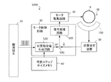
- FIG. 1 is a block diagram illustrating an exemplary basic configuration of a motor module according to the present disclosure.
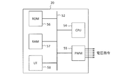
- FIG. 2 is a diagram illustrating an example of a hardware configuration of the motor control circuit 20 in the motor module according to the present disclosure.
- FIG. 3A is a diagram schematically illustrating functional blocks of the motor control circuit 20.
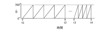
- FIG. 3B is a diagram illustrating an example of a signal indicating the estimated position value ⁇ ⁇ of the rotor R output from the position estimation device 30.
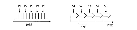
- FIG. 4A is a diagram schematically showing a relationship between a waveform example (left side) of a pulse signal given to the motor module 1000 from the external device 70 of FIG. 1 and a position change (right side) of the rotor R.
- FIG. 1 is a block diagram illustrating an exemplary basic configuration of a motor module according to the present disclosure.
- FIG. 2 is a diagram illustrating an example of a hardware configuration of the motor control circuit 20 in the motor module according to the present disclosure.
- FIG. 4B is a diagram schematically illustrating another example of the relationship between the waveform example (left side) of the pulse signal supplied from the external device 70 to the motor module 1000 and the position change of the rotor R (right side).
- FIG. 4C is a diagram schematically showing still another example of the relationship between the waveform example (left side) of the pulse signal given from the external device 70 to the motor module 1000 and the position change of the rotor R (right side).
- FIG. 4D is a diagram schematically illustrating still another example of the relationship between the waveform example (left side) of the pulse signal given from the external device 70 to the motor module 1000 and the position change of the rotor R (right side).
- FIG. 4C is a diagram schematically showing still another example of the relationship between the waveform example (left side) of the pulse signal given from the external device 70 to the motor module 1000 and the position change of the rotor R (right side).
- FIG. 4D is a diagram schematically illustrating still another example of the relationship between the waveform example (left
- FIG. 5A is a diagram schematically showing still another relationship between a waveform example (left side) of a pulse signal given from the external device 70 to the motor module 1000 and a change in the position of the rotor R (right side).
- FIG. 5B is a diagram schematically showing still another example of the relationship between the waveform example (left side) of the pulse signal given from the external device 70 to the motor module 1000 and the position change of the rotor R (right side).
- FIG. 6 is a graph showing the relationship between the rotational speed of the rotor R and time (upper stage), and a waveform example (lower stage) of a pulse signal given from the external device 70 to the motor module 1000.
- FIG. 7 is a diagram illustrating an example of position command value generation circuits 520A and 520B that can receive a signal designating the rotation direction of the rotor R.
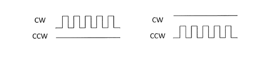
- FIG. 8A is a diagram illustrating waveforms of signals input to the CW terminal and the CCW terminal of the position command value generation circuit 520A.
- FIG. 8B is a diagram illustrating another example of waveforms of signals input to the STMP terminal and the DIR terminal of the position command value generation circuit 520B.
- FIG. 8C is a diagram illustrating still another example of a waveform of a signal input to the STMP terminal and the DIR terminal of the position command value generation circuit 520B.
- FIG. 9 is a diagram illustrating a detailed configuration example of functional blocks of the motor control circuit 20 according to the present disclosure.
- FIG. 10 is a block diagram illustrating a configuration example of the position command value generation circuit 520.
- FIG. 11 is a flowchart showing an example of a position command value generation operation by the position command value generation circuit 520.
- FIG. 12 is a schematic diagram illustrating an example of the configuration of the motor module 1000 according to the embodiment of the present disclosure.
- FIG. 13 is a schematic configuration diagram of a motor M according to the embodiment.
- FIG. 14 is a diagram illustrating an example of detection signals Hu0, Hv0, and Hw0 output from the amplifier circuit 200 according to the embodiment.
- FIG. 15 is a diagram illustrating an example of detection signals Hu0 ′, Hv0 ′, and Hw0 ′ output from the AD converter 31 according to the embodiment.
- FIG. 16 is a diagram illustrating the magnitude relationship, intersection, zero-cross point, and divided signal of three detection signals Hu0 ′, Hv0 ′, and Hw0 ′ according to the embodiment.
- FIG. 17 is a diagram illustrating connection of divided signals for one electrical angle cycle according to the embodiment.
- FIG. 18 is a diagram illustrating a specific example of connection for one cycle of the mechanical angle of the divided signal of the operation by the line segment connection unit 323.
- FIG. 19 is a schematic diagram illustrating another configuration example of the motor module 1000 according to the embodiment.
- CW rotation is rotation in the clockwise direction when viewed from the output shaft side of the motor.
- CCW rotation is rotation in the counterclockwise direction when viewed from the output shaft side.
- the motor module 1000 illustrated in FIG. 1 includes a motor M and a motor step operation control system 1 that controls the operation of the motor M.
- the motor M includes a rotor R and a stator (not shown).
- a typical example of the motor M in the present disclosure is a brushless DC motor, not a stepping motor.
- the motor step operation control system 1 includes a motor drive circuit 10 that drives the motor M and a motor control circuit 20 that is connected to the motor drive circuit 10, and can cause the motor M to execute a step operation. is there.
- bidirectional white arrows are shown between the blocks. This arrow does not mean that information such as signals and data can always move in two directions. For example, a signal may be sent in one direction from the motor control circuit 20 toward the motor drive circuit 10 between the motor drive circuit 10 and the motor control circuit 20.
- the motor module 1000 is connected to the external device 70.
- the external device 70 in this example includes a stepping motor controller 72 and a host controller 74 that controls the stepping motor controller 72.
- the stepping motor controller 72 outputs a pulse signal for driving a normal stepping motor.
- the motor control circuit 20 can receive this pulse signal and cause the motor M that is not a stepping motor to execute a step operation.
- the motor drive circuit 10 gives a voltage necessary for the operation of the motor M based on the voltage command value output from the motor control circuit 20.
- the motor drive circuit 10 includes, for example, an inverter circuit and a predriver.
- the inverter circuit may be a bridge circuit having a plurality of power transistors.
- the motor drive circuit 10 typically receives a pulse width modulation (PWM) signal from the motor control circuit 20 as a voltage command value, and gives a pseudo sine wave voltage to the motor M.
- PWM pulse width modulation
- the external device 70 includes various control circuits other than the stepping motor controller 72.
- control circuitry may be implemented with one or more application specific integrated circuit chips along with the stepper motor controller 72.
- another motor for example, a brushless DC motor
- the stepping motor can be changed to another type of motor M without changing the basic design of the external device 70 manufactured on the assumption that the stepping motor is used. Is possible.
- the illustrated motor module 1000 further includes a position estimation device 30 that outputs a position estimation signal of the rotor R, and a variable step size memory 40 that stores variable step size information.
- the position estimation signal is a signal indicating the position estimation value of the rotor R.
- the position estimation signal is input from the position estimation device 30 to the motor control circuit 20.
- the position estimation signal output from the position estimation device 30 in this embodiment has a magnitude that varies linearly according to the position of the rotor R, not the pulse train.
- the position estimation signal in the present disclosure is greatly different from the rotational position detection signal output by a known rotary encoder. An outline of the position estimation signal example will be described later with reference to FIG. 3B.
- a typical example of a signal output from the rotary encoder is a two-phase pulse train. If an attempt is made to control the position of the rotor R based on the two-phase pulse train, the position of the rotor R cannot be controlled with a resolution narrower than the pulse interval of the two-phase pulse train.
- the position estimation signal has a magnitude that linearly changes according to a change in the position (mechanical angle) of the rotor R. For this reason, it is possible to position the rotor R without being limited by the resolution of the rotary encoder. As a result, the “rotor position change amount (step size)” with respect to one pulse of the pulse signal transmitted by the external device 70 can be freely changed.
- variable step size information The information that defines the “rotor position change amount” for one pulse of the pulse signal input from the external device 70, that is, “variable step size information” is stored in the variable step size memory 40.
- a rotor position change amount (rotation angle) with respect to one pulse of a pulse signal in a stepping motor is referred to as a “step angle”.
- the step angle is 0.9 °
- the change in the position of the rotor with respect to one pulse of the pulse signal is 0.9 °.
- the minimum unit of the step angle is determined by the mechanical structure of the motor.
- the rotor cannot be positioned at any angle smaller than 0.9 °.
- the position change amount of the rotor with respect to one pulse of the pulse signal can be determined without being restricted by the mechanical structure of the motor. Details of this will be described later.
- the motor control circuit 20 When receiving the pulse signal from the external device 70, the motor control circuit 20 according to the present disclosure is based on the estimated position value of the rotor R acquired from the position estimation device 30 and the variable step size information read from the variable step size memory 40. The voltage command value is determined. The motor drive circuit 10 drives the motor M based on this voltage command value, and changes the position of the rotor R.
- the motor control circuit 20 may have a hardware configuration shown in FIG.
- the motor control circuit 20 includes a CPU (central processing unit) 54, a PWM circuit 55, a ROM (read only memory) 56, a RAM (random access memory) 57, and an I / F (input / output interface) connected to each other via a bus. 58).
- Other circuits or devices not shown in the figure may be additionally connected to the bus.
- the PWM circuit 55 gives a PWM signal to the motor drive circuit 10 of FIG.
- Programs and data that define the operation of the CPU 54 are stored in at least one of the ROM 56 and the RAM 57.
- Such a motor control circuit 20 can be realized by, for example, a 32-bit general-purpose microcontroller.
- Such a microcontroller can be comprised of, for example, one or more integrated circuit chips.
- variable step size memory 40 described above is illustrated separately from the motor control circuit 20 in FIG. 1, but at least one of the ROM 56 and the RAM 57 in the motor control circuit 20 realizes the variable step size memory 40. You may do it. Further, the motor control circuit 20 may realize part or all of the functions of the position estimation device 30.
- various operations performed by the motor control circuit 20 are defined by a program. It is possible to change part or all of the operation of the motor control circuit 20 by updating part or all of the contents of the program. Such a program update may be performed using a recording medium storing the program, or may be performed by wired or wireless communication. Communication can be performed using the I / F 58 of FIG. In order to reduce the calculation amount of the CPU 54 shown in FIG. 2, some of various operations performed by the motor control circuit 20, for example, a part of vector calculation, may be executed by a hardware circuit dedicated to the calculation.
- FIG. 3A is a diagram schematically showing functional blocks of the motor control circuit 20.
- the illustrated motor control circuit 20 includes a signal processing circuit 500, a position command value generation circuit 520, and a computing unit 540.
- the position command value generation circuit 520 generates a position command value ⁇ * based on the pulse signal input from the external device 70 and inputs the position command value ⁇ * to the calculator 540.
- the position estimation value ⁇ ⁇ output from the position estimation device 30 is also input to the calculator 540.
- the motor control circuit 20 controls the motor drive circuit 10 to drive the motor M until the estimated position value ⁇ ⁇ received from the position estimation device 30 becomes equal to the position command value ⁇ *.
- the motor control circuit 20 outputs a PWM signal as a voltage command value, the cycle in which the voltage command value is output may be called a “PWM cycle”.
- FIG. 3B is a diagram illustrating a waveform example of a signal indicating the position estimation value ⁇ ⁇ output from the position estimation device 30.
- the magnitude of the signal indicating the position estimation value ⁇ ⁇ increases linearly from zero to a predetermined value.
- the magnitude of the signal indicating the position estimated value ⁇ ⁇ changes continuously and linearly.
- the magnitude of the signal indicating the position estimated value ⁇ ⁇ varies periodically. This period corresponds to the time for which the rotor R makes one rotation.
- the signal indicating the position estimation value ⁇ ⁇ has different magnitudes.
- the mechanical angle (position) of the rotor R can be uniquely specified from the magnitude of the signal indicating the position estimated value ⁇ ⁇ .
- the rotor R rotates four times at a constant rotational speed during the period from time t1 to time t2. Further, the rotor R rotates four times at a constant rotational speed during the period from time t3 to time t4. The rotational speed during the period from time t3 to time t4 is higher than the rotational speed during the period from time t1 to time t2.
- FIG. 4A is a diagram schematically showing a relationship between a waveform example (left side) of a pulse signal given to the motor module 1000 from the external device 70 of FIG. 1 and a position change (right side) of the rotor R.
- the motor control circuit 20 of the motor module 1000 sequentially receives a pulse P1, a pulse P2, a pulse P3, a pulse P4, and a pulse P5 from the stepping motor controller 72 of the external device 70.
- Such pulses can be input to the motor control circuit 20 at a rate of several tens to several hundreds of thousands in one second, for example.
- the rotor R rotates in response to the pulse signal.
- the position change amount of the rotor R with respect to one pulse that is, the step angles S1 to S5 is 0.9 °.
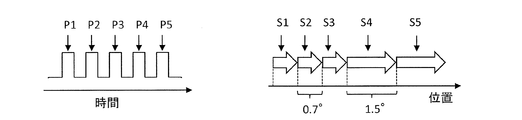
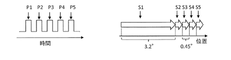
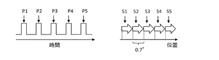
- FIGS. 4A to 4D show other examples of the relationship between the waveform example (left side) of the pulse signal given to the motor module 1000 from the external device 70 of FIG. 1 and the position change (right side) of the rotor R, respectively. It is a figure which shows an example typically. In any example, the waveform example (left side) of the pulse signal supplied from the external device 70 to the motor module 1000 is the same.
- the hardware of the motor module 1000 is common in the examples of FIGS. 4A to 4D.
- the position change amount of the rotor R with respect to one pulse that is, the step angles S1 to S5 is 0.7 ° unlike the example of FIG. 4A.
- variable step size information used for the calculation.
- the setting or changing of the variable step size information can be performed for each motor module 1000 at the time of production or shipment of the motor module 1000, but for each motor module 1000, it is performed at the time of starting or during the operation. Is also possible. In the following example, variable step size information is changed during the operation.
- the position change amount of the rotor R with respect to one pulse that is, the step angle is 0.7 ° with respect to the pulses P1 to P3, but is 1.5 ° with respect to the pulses P4 to P5.
- the step angle in this example changes during the operation. Before and after this change, one step angle is not an integer multiple of the other step angle.
- the position change amount of the rotor R with respect to one pulse that is, the step angle is 3.2 ° with respect to the pulse P1, and 0.45 ° with respect to the pulses P2 to P5. It is also possible to extremely increase the position change amount of the rotor R with respect to one pulse. For example, it is possible to move the rotor R one rotation (360 °) or more in response to one pulse.
- FIGS. 5A and 5B are diagrams schematically showing a relationship between a waveform example (left side) of a pulse signal given from the external device 70 of FIG. 1 to the motor module 1000 and a change in position of the rotor R (right side). is there.
- the difference between the example of FIG. 5A and the example of FIG. 5B is in the pulse rate of the pulse signal supplied from the external device 70 to the motor module 1000.
- the pulse rate means the number of pulses input to the motor module 1000 per unit time.
- the pulse rate is sometimes called “pulse frequency”.
- the pulse rate of the pulse signal shown in FIG. 5B is lower than the pulse rate of the pulse signal shown in FIG. 5A.
- the step angle is common at 0.7 °, but the rotation speed (position change speed) of the rotor R is different because the pulse rate is different. More specifically, the higher the pulse rate, the higher the rotational speed of the rotor R.
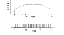
- FIG. 6 is a graph showing the relationship between the rotational speed of the rotor R and time (upper stage), and a waveform example (lower stage) of a pulse signal given from the external device 70 to the motor module 1000.
- the pulse rate increases linearly, and the rotational speed of the rotor R increases accordingly.
- the pulse rate is constant and the rotation speed of the rotor R is also constant.
- the pulse rate is linearly lowered, and the rotational speed of the rotor R is also lowered accordingly.
- the rotational speed of the rotor R can be controlled by the pulse rate included in the pulse signal.
- the motor module 1000 may receive a signal designating the rotation direction of the rotor R from the external device 70.
- FIG. 7 shows an example of a position command value generation circuit 520 that can receive a signal designating the rotation direction of the rotor R.
- the position command value generation circuit 520A shown on the left side of FIG. 7 has a CW terminal and a CCW terminal.
- the position command value generation circuit 520B shown on the right side of FIG. 7 has an STMP terminal and a DIR terminal.
- any position command value generation circuit 520 may be used to specify the rotation direction of the rotor R.
- FIG. 8A is a diagram illustrating waveforms of signals input to the CW terminal and the CCW terminal of the position command value generation circuit 520A.
- the rotation direction of the rotor R differs between when the pulse signal is input to the CW terminal of the position command value generation circuit 520A and when the pulse signal is input to the CCW terminal.
- the rotor R rotates in the first direction
- the rotor R has the second direction opposite to the first direction. Rotate in the direction.
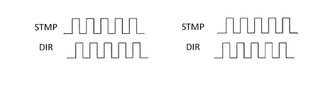
- FIG. 8B is a diagram illustrating another example of waveforms of signals input to the STMP terminal and the DIR terminal of the position command value generation circuit 520B.
- the pulse signal is input to the STMP terminal of the position command value generation circuit 520B.
- the rotation direction of the rotor R varies depending on whether a logic “low” signal or a logic “high” signal is applied to the DIR terminal. For example, when a logic low signal is applied to the DIR terminal, the rotor R rotates in the first direction. When a logic high signal is applied to the DIR terminal, the rotor R rotates in a second direction opposite to the first direction.
- FIG. 8C is a diagram illustrating another example of waveforms of signals input to the STMP terminal and the DIR terminal of the position command value generation circuit 520B.
- a two-phase pulse signal is applied to the STMP terminal and the DIR terminal of the position command value generation circuit 520B.
- the rotational direction of the rotor R varies depending on the phase advance / delay. For example, when the phase of the pulse signal input to the STMP terminal is ahead of the phase of the pulse signal input to the DIR terminal, the rotor R rotates in the first direction. When the phase of the pulse signal input to the STMP terminal is delayed from the phase of the pulse signal input to the DIR terminal, the rotor R rotates in the second direction opposite to the first direction.
- the terminal configuration of the above waveform and position command value generation circuit 520 is merely a typical example and does not limit the embodiment of the present disclosure.
- FIG. 9 is a diagram illustrating a configuration example of functional blocks of the motor control circuit 20 according to the present disclosure.
- the motor control circuit 20, the position estimation device 30, and the variable step size memory 40 are realized by a microcontroller.
- a microcontroller is referred to as a “motor control device” and may be indicated by a reference numeral “100”.
- the motor control circuit 20 shown in FIG. 9 includes a position command value generation circuit 520, a speed command value generation circuit 545, comparators 550a and 550b, and a speed command value generation circuit 560.
- a position command value generation circuit 520 includes a position command value generation circuit 520, a speed command value generation circuit 545, comparators 550a and 550b, and a speed command value generation circuit 560.
- the description of the term “circuit” of each component is omitted for the sake of simplicity.
- the position command value generation circuit 520 receives a pulse signal as exemplified in FIGS. 8A, 8B, and 8C, for example, and generates a position command value ⁇ *.
- the position command value generation circuit 520 may store the contents of the variable step size memory 40 as a table.
- the position command value generation circuit 520 may have the configuration shown in FIG.
- the position command value generation circuit 520 includes a memory that performs the same function as the variable step size memory as a table.
- the position command value generation circuit 520 includes a plurality of terminals that receive signals (external signals) output from the external device 70 of FIG.
- the plurality of terminals include an STMP terminal, a DIR terminal, and an ST-SIZE terminal.
- the STMP terminal and the DIR terminal receive the pulse signal from the stepping motor controller 72 of FIG.
- the ST-SIZE terminal receives an external signal specifying the step size from the external device 70.
- the external signal designating the step size specifies a number in a table provided in the position command value generation circuit 520, and reads a value (table value) determined by the number.
- the table numbers are, for example, “0”, “1”, “2”, and “3”.
- the table numbers “0”, “1”, “2”, and “3” are values of, for example, “0.45”, “0.90”, “1.80”, and “10.0”, respectively. have.
- the plurality of table values are candidate values for the step size (step angle).
- the signal indicating the table number can be output from, for example, the host controller 74 of the external device 70 of FIG.
- table numbers “0”, “1”, “2”, and “3” are assigned to four ST-SIZE terminals, respectively.
- a logic “high” potential is given to one of the four ST-SIZE terminals from the external device 70 as a signal for specifying the step size, and the other three terminals have For example, a logic “low” potential is applied.
- a table value of “0.45” is given to one ST-SIZE terminal to which a logic “high” voltage is given, 0.45 ° is used as the step size.
- the step size can be determined, for example, at startup. It is also possible to change the step size during operation.
- the motor control device 100 may include a pin or interface that selects any one of a plurality of candidate values stored in the variable step size memory 40.
- the table number may be specified by 1-bit or more data. In that case, any one value can be designated from 2 m step size candidates using m ST-SIZE terminals.
- the table number may be specified by a communication means such as serial communication. Such step size designation may be performed by the host controller 74 in the external device 70 of FIG. 1 or may be performed by another controller. Further, the step size may be selected by a manufacturer or user of the motor module 1000 by a mechanical switch. Values stored in the table or the variable step size memory 40 can be updated from the outside.
- the position command value generation circuit 520 in an embodiment generates a position command value ⁇ * based on the following equation.
- ⁇ * ⁇ set ⁇ N_STMP ⁇ Dir + ⁇ ⁇ (Formula 1)
- ⁇ ⁇ is the estimated position value
- ⁇ set is the step size
- N_STMP is the pulse count number of the pulse signal input from the external device 70 within the set period
- Dir is the rotor rotation direction (position change direction) It is a code to do.
- the current position estimated value ⁇ ⁇ of the rotor R acquired from the position estimating device 30 is 112.4 °.
- the position command value generation circuit 520 outputs a digital signal indicating a position command value of 134.9 °.
- the position command value output from the position command value generation circuit 520 is given to the comparator 550a.
- the comparator 550a compares the position estimated value acquired from the position estimation device 30 with the position command value acquired from the position command value generation circuit 520, and outputs a deviation between the position estimated value and the position command value.
- the speed command value generation circuit 560 generates a speed command value based on the value of the comparator 550a.
- the speed command value output from the speed command value generation circuit 560 is given to the comparator 550b.
- the comparator 550b compares the speed estimated value acquired from the speed estimated value generation circuit 545 with the speed command value, and outputs a deviation.
- the motor control circuit 20 determines a voltage command value and outputs a PWM signal indicating the voltage command value from the PWM signal generation circuit 570.
- the determination of the voltage command value can be executed, for example, by calculation using a known vector control technique.
- the current control is omitted, but the current control may be performed after the speed control. Moreover, it is not limited to the combination of position control and speed control.
- the motor control circuit 20 may generate the position command value and the speed command value based on the variable step size information and the pulse signal.
- step S10 the motor module is started in step S10.
- step S12 the presence / absence of an external input signal that specifies a step angle as the step size is confirmed.
- the signal on the ST-SIZE terminal is read as an external input signal.
- step S14 the value ⁇ step1 specified by the external input signal is selected as the step angle ⁇ set. This value is any one of a plurality of candidate values stored in the table of FIG. 10, for example.
- step S12 when an external input signal is not detected, the process proceeds to step S16.
- step S16 the value ⁇ step2 specified by another signal line is selected as the step angle ⁇ set.
- the potential of the signal line is controlled by, for example, ON / OFF of a switch included in the motor module 1000, and identifies one of a plurality of candidate values stored in the table.
- step S18 it is determined whether or not to start the operation mode of the motor M. If you do not start the operation mode, wait. When starting the operation mode, the process proceeds to step S20.
- step S20 the current position estimation value ⁇ ⁇ of the rotor is acquired from the position estimation device 30.
- step S22 the number of pulses in the pulse signal input from the external device 70 is counted. The pulse count value within a predetermined period is N_STMP.
- step S24 the position command value ⁇ * is determined using Equation 1 described above.
- step S26 the rotor position control (motor drive) is performed using the position command value ⁇ * and the estimated position value. This motor drive may be executed according to a known control technique.
- step S28 it is determined whether or not the step angle ⁇ set needs to be switched. When it is not necessary to switch the step angle ⁇ set, the process returns to step S22. When the step angle ⁇ set is switched, the next value ⁇ step3 is selected as the step angle ⁇ set in step S30.
- step S28 The necessity of switching the step angle ⁇ set in step S28 can be determined, for example, according to the following condition example.
- one of a plurality of candidate values is selectively read out from the variable step size memory 40 at the time of startup or during operation in accordance with a program built in the motor control device 100 or an external command. be able to.
- FIG. 12 is a schematic diagram illustrating a configuration example of the motor module 1000 according to the embodiment of the present disclosure.
- the motor module 1000 in this embodiment includes a motor M, a detection device 150, an amplification circuit 200, a position estimation device 30, a motor control device (control circuit) 20, and a motor drive circuit (drive circuit) 10.
- the motor M in the present embodiment is a brushless DC motor and has a rotor R that rotates around a central axis.
- the motor module 1000 receives an external signal such as a pulse signal that specifies the rotational position of the rotor R from an external device (controller) 70.
- the motor module 1000 is used by being attached to a product.
- the product can be, for example, an electric machine such as a multifunction machine having functions such as a printer, a scanner, and a facsimile machine, an electric power steering, an antenna tilt, and a fan.
- the motor M of the motor module 1000 is used by being attached to a mechanism unit (mechanical part) such as a paper feed function unit, for example.
- One multifunction device may include a plurality of motor modules 1000.
- the motor M includes a rotor R.
- the motor M is, for example, a permanent magnet motor.
- a substrate (not shown) is attached to the motor M.
- a detection device 150, an amplifier circuit 200, a position estimation device 30, a motor control circuit 20, and a motor drive circuit 10 are attached.
- the motor M may be a linear motor.
- the motor M includes a mover (movable or movable element) that moves linearly instead of the rotor R.
- the term “mover” includes not only a rotor but also a part that moves linearly in a linear motor.
- CW means a first direction on a straight line
- CCW means a second direction opposite to the first direction on the same straight line.
- the detection device 150 includes sensors 11 to 13. Each of the sensors 11 to 13 is a non-contact magnetic sensor that converts a magnetic field generated in the motor M into an electric signal and outputs the electric signal. Each of the sensors 11 to 13 is, for example, a hall element.
- the detection device 150 outputs the detected differential sensor signal to the amplifier circuit 200.
- the operation of the motor module 1000 in this embodiment has a signal detection procedure. In the signal detection procedure, each of the N detection devices (N is an integer of 3 or more) detects a magnetic field corresponding to the position of the rotor and outputs a detection signal that is an electrical signal. Each detection signal is out of phase by an angle obtained by dividing 360 degrees by N.
- N is an integer of 3 or more
- a magnetic field formed by a plurality of magnetic poles is detected, and a detection signal having a magnitude corresponding to the detected magnetic field strength. Is output.
- the N sensors are arranged such that the phases of the N detection signals are shifted by an angle of 360 degrees / N.
- the state where the phase of the detection signal is shifted by an angle of 360 degrees / N includes a state where the phase is shifted by an electrical angle of 360 degrees ⁇ integer ⁇ 360 degrees / N.
- the amplifier circuit 200 includes a differential amplifier 21 to a differential amplifier 23.
- the amplifier circuit 200 generates a detection signal Hu0, a detection signal Hv0, and a detection signal Hw0 based on the differential sensor signal input from the detection device 150.
- the amplifier circuit 200 outputs the generated detection signal Hu0, detection signal Hv0, and detection signal Hw0 to the position estimation device 30. Note that each of the detection signal Hu0, the detection signal Hv0, and the detection signal Hw0 is an analog signal.
- the position estimation device 30 estimates the rotational position of the rotor R based on the detection signal Hu0, the detection signal Hv0, and the detection signal Hw0 input from the amplifier circuit 200.
- the position estimation device 30 generates a position estimated value ⁇ ⁇ based on the estimated rotational position (mechanical angle), and gives the generated position estimated value ⁇ ⁇ to the motor control circuit 20.
- the motor control circuit 20 receives the position estimation value ⁇ ⁇ from the position estimation device 30 and the pulse signal from the external device 70. As described above, the motor control circuit 20 generates a voltage command for driving the motor M, and outputs the generated voltage command to the motor drive circuit 10.
- the motor drive circuit 10 generates a drive signal based on the voltage command input from the motor control circuit 20, and drives the motor M by the generated drive signal.
- One typical example of the motor drive circuit 10 is an inverter circuit.
- An inverter circuit receives a voltage command and outputs a pulse width modulation (PWM) signal, a PWM circuit, a pre-driver circuit that outputs a gate drive signal based on the PWM signal, and an inverter output circuit that receives and switches the gate drive signal Can be provided.
- PWM pulse width modulation
- the motor control circuit 20 and a part of the motor drive circuit 10 may be realized by a single integrated circuit package.
- Such an integrated circuit package is available as a general-purpose motor control microcomputer.
- the inverter output circuit of the drive circuit 10 may be called a power module.
- Such an inverter output circuit can drive the motor M by applying a voltage having a magnitude corresponding to the voltage command to each coil of the motor M.
- the motor module 1000 receives the pulse signal from the external device 70 and generates the position command value ⁇ *. Then, the motor is controlled by feeding back the deviation between the position command value ⁇ * and the position estimated value ⁇ ⁇ .
- the position estimation signal indicating the position estimation value ⁇ ⁇ has a magnitude that linearly changes according to the position (angle) of the rotor R. More specifically, the magnitude of the position estimation signal changes not continuously but continuously in a straight line when the rotor R makes one revolution. An example of generating such a position estimation signal will be described in detail below.
- the motor module 1000 in the present embodiment sequentially detects intersections where the detection signals Hu0, Hv0, and Hw0 intersect each other. A part (divided line segment) of the detection signals Hu0, Hv0, or Hw0 from the detected intersection to another intersection adjacent to the intersection is detected as a divided signal (see FIG. 16).
- a portion that connects or links from the intersection to another intersection adjacent to the intersection is included in the detection signals Hu0, Hv0, and Hw0. It is a part of any one signal Hu0, Hv0, or Hw0 having an intermediate level. As shown in FIG. 16, a portion connecting from an intersection to another intersection adjacent to the intersection intersects the reference value level. In other words, a portion connecting from the intersection to another intersection adjacent to the intersection has a portion larger than the reference value and a portion smaller than the reference value.
- a portion connecting from an intersection to another intersection adjacent to the intersection can be processed as one “divided signal” or can be processed as two “divided signals”. In the latter case, a portion connecting from the intersection to another intersection adjacent to the intersection is bisected by a zero cross point that intersects the reference value. A portion connecting from an intersection to another intersection adjacent to the intersection may be divided into three or more “divided signals”.
- the motor module 1000 sequentially connects the detected divided signals in accordance with the moving direction of the rotor, and estimates the position of the rotor based on the plurality of connected divided signals to generate a position estimation signal (FIG. 17).
- FIG. 18 The estimated position value can be used as a feedback value in a current control system, a speed control system, a position control system, or a control system that combines these.
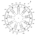
- FIG. 13 is a schematic configuration diagram of the motor M according to the present embodiment.
- the motor M is a permanent magnet motor.
- the magnetic poles p1 to p12 are magnetic poles (poles) of the permanent magnet motor.
- the number of poles represents the number of magnetic poles in the motor M, and is 12 in the example shown in FIG.
- the number of pole pairs is the number of pairs of N poles and S poles, and is 6 in the example shown in FIG.
- the slots sl1 to sl9 are armatures (stators) around which coils are wound.
- the number of slots of the permanent magnet motor in this embodiment is nine.
- the magnetic poles p1 to p12 are a part of the rotor R (see FIG. 12).
- a motor M in FIG. 13 represents an outer rotor type motor.
- Each of the sensors 11 to 13 detects a magnetic field generated by a pair of adjacent north and south poles and outputs a signal for one cycle. This corresponds to one electrical angle cycle.
- Each of the sensors 11 to 13 outputs the detected electrical signal for one electrical angle cycle to the amplifier circuit 200 as a differential sensor signal. This one-cycle differential sensor signal corresponds to one electrical angle cycle.
- each of the sensors 11 to 13 detects an electrical signal whose phase is shifted by 120 degrees and outputs it to the corresponding differential amplifier 21 to differential amplifier 23. That is, the number of sensors included in the detection device 150 is three, and the phases of the three detection signals are shifted by 120 degrees. In a specific example, the sensors 11 to 13 detect an electrical signal whose phase is shifted by 40 degrees mechanical angle (240 electrical degrees).
- the electrical signal detected by the sensor 11 is the U phase.
- the electrical signal detected by the sensor 12 is assumed to be V phase.
- the electrical signal detected by the sensor 13 is assumed to be the W phase.
- the differential sensor signals output from the sensor 11 are differential sensor signals U0 + and U0 ⁇ , which are in an inverted relationship with each other.
- the differential sensor signals output from the sensor 12 are differential sensor signals V0 + and V0 ⁇ , which are in an inverted relationship with each other.
- the differential sensor signals output from the sensor 13 are detection signals W0 + and W0 ⁇ , which are in an inverted relationship with each other.
- the differential amplifier 21 amplifies the voltage difference between the U-phase detection signals U0 ⁇ and U0 + input from the sensor 11, and outputs the amplified detection signal Hu0 to the position estimation device 30.
- the differential amplifier 22 amplifies the voltage difference between the V-phase detection signals V0 ⁇ and V0 + input from the sensor 12, and outputs the amplified detection signal Hv0 to the position estimation device 30.
- the differential amplifier 23 amplifies the voltage difference between the W-phase detection signals W0 ⁇ and W0 + input from the sensor 13, and outputs the amplified detection signal Hw0 to the position estimation device 30.
- FIG. 14 is a diagram illustrating an example of detection signals Hu0, Hv0, and Hw0 output from the amplifier circuit 200 according to the present embodiment.
- the horizontal axis represents the rotor angle [deg].
- the vertical axis represents the magnitude of the signal.
- the section E1 from the rotor angle ⁇ 101 to the rotor angle ⁇ 113 represents one electrical angle cycle.
- Each section E6 of the angle ⁇ 118 represents one electrical angle period.
- a section K1 from the section E1 to the section E6 represents one period of the mechanical angle. That is, the section for one electrical angle cycle is a section obtained by dividing the section for one mechanical angle cycle by the number of pole pairs.
- the maximum value of the detection signal Hu0 is A3 [V].
- the maximum value of the detection signal Hw0 is PeakHw [V], which is smaller than the voltage value of A3.
- the maximum value of the detection signal Hv0 is PeakHv [V], which is smaller than the voltage value of PeakHw.
- the detection signals Hu0, Hv0, and Hw0 vary in amplitude due to the mounting error of the sensors 11 to 13 or the difference in sensitivity among the sensors.
- the signals Hu0, Hv0, and Hw0 have different center voltage values. That is, each of the signals Hu0, Hv0, and Hw0 has an offset component.
- the position estimation device 30 includes an AD converter 31, a position calculation unit 32, and a storage device 33.
- the AD converter 31 converts the analog signal detection signal input from the amplifier circuit 200 into a digital signal detection signal, and outputs the converted digital signal detection signal to the position calculation unit 32. More specifically, an AD conversion circuit 311, an AD conversion circuit 312, and an AD conversion circuit 313 are provided.
- the AD conversion circuit 311 converts the analog signal detection signal Hu0 into a digital signal detection signal Hu0 'and outputs the detection signal Hu0' to the position calculation unit 32.
- the AD conversion circuit 312 converts the detection signal Hv0 of the analog signal into the detection signal Hv0 ′ of the digital signal and outputs it to the position calculation unit 32.
- the AD conversion circuit 313 converts the analog signal detection signal Hw 0 into a digital signal detection signal Hw 0 ′ and outputs the detection signal Hw 0 ′ to the position calculation unit 32.
- the storage device 33 stores information used in online processing. The online processing is processing performed in real time when the rotor R is rotating. Information stored in the storage device 33 will be described later.
- converting the detection signal into a signal suitable for processing in the position calculation unit 32 can be referred to as “preprocessing”.
- the AD converter 31 is an example of a circuit that performs preprocessing.
- the position calculation unit 32 may be provided with a circuit that performs other preprocessing.
- the position calculation unit 32 includes an intersection position detection device 321, a division detection device 322, and a line segment connection unit 323.
- the intersection position detection device 321 detects an intersection between the detection signals and a zero cross point between the detection signal and the reference value. That is, between the intersection and another intersection adjacent to the intersection, the intersection position detection device 321 sequentially detects a zero-cross point where the potential of the detection signal intersects the reference voltage from the intersection.
- the reference value is a value whose digital value indicates 0.
- the intersection position detection device 321 outputs information indicating the coordinates of the detected intersection and information indicating the coordinates of the zero cross point to the division detection device 322.
- the information indicating the coordinates of the intersection and the zero-cross point is information represented by the rotor angle and the magnitude of the digital value.
- the division detection device 322 detects a detection signal between the intersection and the zero cross point as a division signal. When detecting, the information indicating the coordinates of the intersection input from the intersection position detection device 321 and the information indicating the coordinates of the zero-cross point are used.
- the division detection device 322 outputs information indicating the detected division signal to the line segment connection unit 323.
- the line segment connection unit 323 sequentially connects the divided signals using information indicating the divided signals input from the division detection device 322.
- the information indicating the divided signal is information represented by the rotor angle and the magnitude of the digital value from the start position to the end position of the divided signal that is a part of the detection signal.
- the operation of the motor module 1000 in the present embodiment includes the intersection position detection procedure, the division detection procedure, and the line segment connection procedure.
- the intersection position detection procedure the intersection position detection device 321 sequentially detects intersections at which the respective detection signals output by the signal detection procedure intersect each other.
- the division detection procedure the division detection device 322 detects a portion of the detection signal connected from the intersection to another intersection adjacent to the intersection as one or a plurality of divided signals.
- the line segment connection procedure the line segment connection unit 323 sequentially connects the divided signals. Then, the position of the rotor is estimated based on the plurality of connected divided signals to generate a position estimation signal.
- the position estimation device 30 performs the following processing by online processing.
- the intersection position detection device 321 acquires detection signals Hu0 ', Hv0', and Hw0 'input from the AD converter 31.
- the intersection position detection device 321 sequentially detects the intersection and the zero-cross point using the values indicated by the detection signals Hu0 ′, Hv0 ′, and Hw0 ′ acquired in the procedure S101.
- the intersection position detection device 321 sequentially outputs information indicating the coordinates of the detected intersection and zero-cross point and the input detection signals Hu0 ′, Hv0 ′, and Hw0 ′ to the division detection device 322.
- Step S103 The division detection device 322 detects a part of the detection signal from the intersection to the zero cross point adjacent to the intersection, that is, the portion of the detection signal from the intersection to the zero cross point adjacent to the intersection. It detects as the 1st division signal. Alternatively, the split detection device 322 may select a part of the detection signal from the zero cross point to the intersection adjacent to the zero cross point, that is, a part from the zero cross point of the detection signal to the intersection adjacent to the zero cross point. It is detected as a divided signal.
- Step S104 When the rotor R is in CW rotation, the line segment connection unit 323 sequentially connects the division signals input from the division detection device 322 for one period of the mechanical angle in the forward direction.
- the position estimation device 30 determines the position estimated value ⁇ ⁇ by estimating the machine position based on the divided signal connected by the line segment connecting unit 323.
- the position estimation device 30 repeats the processing from step S101 to step S105 every control cycle.
- the control cycle is, for example, any one cycle among control cycles of current (torque), speed, or position control.
- the crossing position detection device 321 acquires detection signals Hu0 ′, Hv0 ′, and Hw0 ′ input from the AD conversion circuit 311 to the AD conversion circuit 313, respectively.
- the detection signal Hu0 ', detection signal Hv0', and detection signal Hw0 'output from the AD converter 31 will be described with reference to FIG.
- FIG. 15 is a diagram illustrating an example of detection signals Hu0 ′, Hv0 ′, and Hw0 ′ output from the AD converter 31 according to the present embodiment.
- the horizontal axis represents the rotor angle [deg].
- the vertical axis represents a digital value.
- Each of the waveforms Hu0 ′, Hv0 ′, and Hw0 ′ shown in FIG. 15 is a waveform diagram that represents the detection signal converted into a digital signal by the AD conversion circuit 311 to the AD conversion circuit 313.
- the AD converter 31 has 12 bits
- the range of the digital signal value is +2047 to -2048.
- the section E1 between the rotor angle ⁇ 101 and the rotor angle ⁇ 113 is one electrical angle cycle.
- the crossing position detection device 321 acquires the detection signals Hu0 ′, Hv0 ′, and Hw0 ′ output from the AD converter 31.
- the intersection position detection device 321 sequentially detects the intersection of the acquired detection signals by calculating from the coordinates between the two sampled points.
- the intersection position detection device 321 sequentially detects a zero-cross point between the acquired detection signal and the reference value.
- the coordinates of the intersection and the zero cross point can be indicated by the rotor angle on the horizontal axis and the digital value on the vertical axis.
- the intersection position detection device 321 detects the coordinates of the intersection, and outputs information indicating the detected coordinates of the intersection to the division detection device 322.
- the crossing position detection device 321 detects the coordinates of the zero cross point, and outputs information indicating the coordinates of the detected zero cross point to the division detection device 322. Further, the intersection position detection device 321 outputs the acquired detection signals Hu0 ′, Hv0 ′, and Hw0 ′ to the division detection device 322.
- the division detection device 322 sequentially acquires information indicating the coordinates of the intersection input from the intersection position detection device 321, information indicating the coordinates of the zero cross point, and detection signals Hu 0 ′, Hv 0 ′, and Hw 0 ′.
- the division detection device 322 detects a detection signal from the intersection to the zero cross point adjacent to the intersection among the acquired detection signals as a first division signal.
- the division detection device 322 detects, as a second division signal, a detection signal from the zero cross point to the intersection adjacent to the zero cross point among the acquired detection signals.
- the division detection device 322 sequentially outputs the detected division signals to the line segment connection unit 323.
- the division detection device 322 detects information indicating the first division signal.
- the information indicating the first divided signal is information on the deviation of the digital value and the deviation of the rotor angle from the intersection to the zero-crossing point adjacent to the intersection.
- intersection position detection device 321 First, specific examples of the intersection and the zero cross point detected by the intersection position detection device 321 will be described with reference to FIG.
- FIG. 16 is a diagram for explaining the magnitude relationship, intersection, zero-cross point, and divided signal of the three detection signals Hu0 ′, Hv0 ′, and Hw0 ′ according to the present embodiment.
- the horizontal axis represents the rotor angle [deg].
- the vertical axis represents a digital value.
- FIG. 16 is an enlarged view of a section E1 between the rotor angle ⁇ 101 and the rotor angle ⁇ 113 in FIG.
- each of the points cp1 to cp7 represents an intersection.
- the intersection is a point where two detection signals intersect.
- the intersection cp1 at the rotor angle ⁇ 101 is a point where the detection signal Hu0 ′ and the detection signal Hv0 ′ intersect.
- each of the points zc1 to zc6 represents a zero cross point.
- the zero cross point is a point where any one of the detection signals Hu0 ', Hv0', and Hw0 'intersects a digital value reference value.
- the zero cross point zc1 at the rotor angle ⁇ 102 is a point where the detection signal Hu0 ′ and the reference value intersect.
- a segment refers to each divided signal.
- the segment section corresponds to the segment signal from the start point to the end point.
- the segment is 12 sections in one electrical angle period.
- the number of 1 to 12 divided signals in one electrical angle cycle may be called a section.
- the divided signal is a detection signal from the intersection cp (n) to the zero-crossing point zc (m) adjacent to the intersection cp (n) in FIG.
- N is an integer of 1 to 7.
- M is an integer of 1-6.
- a part of the detection signal Hu0 'from the intersection cp1 to the zero crossing point zc1 is the divided signal sg101.
- a part of the detection signal Hu0 'from the zero cross point zc1 to the cross point cp2 is the divided signal sg102.
- the section of ⁇ 101 to ⁇ 102 that is, the section of the divided signal sg101 corresponds to the section of segment number 1.
- the sections of the divided signals sg102 to sg112 correspond to the sections of segment numbers 2 to 12, respectively.
- the divided signals sg101 to sg112 are signals in a range closer to a straight line than the other parts of the sine waves. .
- the digital value of the detection signal Hw0 ′ is the largest among the three detection signals.
- the detection signal Hu0 ' has the next largest digital value after the detection signal Hw0'.
- the detection signal Hv0 ' has the smallest digital value.
- the digital value of the detection signal Hu0 ' is smaller than the reference value in the section of the rotor angles ⁇ 101 to ⁇ 102 that is the section of the segment 1.
- the digital value of the detection signal Hu 0 ′ is larger than the reference value in the section of the rotor angles ⁇ 102 to ⁇ 103 that is the section 2.
- the storage device 33 stores the combinations of the magnitude relationships of the three detection signals Hu0 ′, Hv0 ′, and Hw0 ′ for each segment of the electrical angle and the magnitude relationship with the reference value.
- the line segment connection unit 323 sequentially connects the division signals of the division detection device 322.
- the line segment connection unit 323 is configured to divide the divided signal in a certain direction with respect to the positive / negative of the digital value according to the magnitude relationship between the intersection or zero-cross point and the detection signals Hu0 ′, Hv0 ′, Hw0 ′ and the reference value. Connect to.
- the line segment connecting unit 323 has a middle rank in the magnitude relationship between the digital values of the detection signals Hu0 ′, Hv0 ′, and Hw0 ′ for each segment (in the example of FIG. 16, the larger (smaller)).
- the second detection signal also referred to as an intermediate signal
- the line segment connecting unit 323 compares each extracted digital value of the intermediate signal with the magnitude relationship between the digital value of the detection signal (also referred to as a cross point signal value) at the immediately preceding intersection or zero cross point.
- the immediately preceding intersection or zero-crossing point is the point immediately preceding the intermediate signal in the rotor angle direction.
- the crossing point cp1 is for the divided signal sg101 and the zero crossing point zc1 is for the divided signal sg102.
- the line segment connecting unit 323 subtracts the previous cross point signal value zc1 from the digital value of the intermediate signal sg102. Add to signal value zc1.
- the line segment connecting unit 323 adds a value obtained by subtracting the digital value of the intermediate signal sg102 from the previous cross point signal value zc1. To do.
- the line segment connecting part 323 repeats this addition in order from the smaller rotor angle. Thereby, the line segment connection part 323 can connect a division
- the line segment connecting unit 323 may add the difference between the digital value of the intermediate signal and the previous cross point signal value, that is, the absolute value.
- the end point of the divided signal sg 124 ′ corresponds to a mechanical angle of 120 [degM].
- the end point of the divided signal sg 172 ′ corresponds to a mechanical angle of 360 [degM].
- FIG. 17 is a diagram illustrating connection of divided signals for one electrical angle cycle according to the present embodiment.
- FIG. 17 shows a diagram in which the divided signals sg101 'to sg112' in the section E1 in FIG. 16 are connected.
- the horizontal axis represents the rotor angle [degE].
- the vertical axis represents a digital value.
- the rotor R is rotating CW.
- the divided signals sg101 ′ to sg112 ′ are signals obtained by connecting the divided signals sg101 to sg112 of FIG. 16 through the line segment connection unit 323.
- Points p101 to p113 are points where the intersections cp1 to cp7 and the zero crossing points zc1 to zc6 in FIG. 16 are replaced.
- a curve g132 is a curve obtained by connecting the divided signals sg101 'to sg112'.
- the forward direction is a direction in which the digital value increases as the rotor angle increases.
- the line segment connecting unit 323 replaces the intersection cp1 with the point p101.
- the line segment connection unit 323 connects the divided signal sg101 'in the forward direction.
- the line segment connecting unit 323 replaces the divided signal sg101 in FIG. 16 with a divided signal sg101 'having the point p101 as the start point and the point p102 as the end point.
- the line segment connecting unit 323 replaces the zero cross point zc1 with the point p102.
- the line segment connection unit 323 connects the divided signal sg102 'in the forward direction. Specifically, the divided signal sg101 in FIG. 16 is replaced with a divided signal sg102 'having the point p102 as a start point and the point p103 as an end point. Further, the line segment connecting unit 323 replaces the intersection cp2 with the point p103.
- the line segment connection unit 323 sequentially connects the divided signals sg101 'to sg112' shown in FIG. 16 in the forward direction. As a result, the intersection cp1 at the rotor angle ⁇ 101 is replaced with a digital value 0. Further, the line segment connecting portion 323 replaces the intersection cp7 at the rotor angle ⁇ 113 with a digital value 1200. In FIG. 16, the digital value 12000 corresponds to 360 [degE] for one electrical angle period.
- the line segment connecting unit 323 sequentially connects the divided signals sg101 to sg112 of FIG. 16 in the forward direction for one electrical angle period. As a result, as shown in the divided signal sg101 'to the divided signal sg112' in FIG. 17, the divided signal sg101 to the divided signal sg112 in FIG. 16 are connected.
- the line segment connection unit 323 connects the start point of the divided signal sg113 'in the second period E2 to the end point of the divided signal sg112'. Subsequently, the line segment connection unit 323 connects the divided signals sg113 to sg124 for one electrical angle cycle in the forward direction. As a result, the divided signal sg113 to the divided signal sg124 are connected as indicated by the divided signal sg113 'to the divided signal sg124' in FIG.
- the line segment connecting unit 323 connects the start point of the divided signal sg125 'having the third period E3 to the end point of the divided signal sg124' having the second period E2.
- the line segment connection unit 323 connects the start point of the divided signal sg137 'having the fourth period E4 to the end point of the divided signal sg136' having the third period E3.
- the line segment connection unit 323 connects the start point of the divided signal sg149 'having the fifth period E5 to the end point of the divided signal sg148' having the fourth period E4.
- the line segment connecting unit 323 connects the start point of the divided signal sg161 'having the sixth period E6 to the end point of the divided signal sg160' having the fifth period E5.
- FIG. 18 is a diagram illustrating an example of a connection result of divided signals for one mechanical angle cycle according to the present embodiment.
- each period of one electrical angle includes 12 divided signals.
- the first period E1 includes a divided signal sg101 'to a divided signal sg112'.
- the second period E2 includes a divided signal sg113 'to a divided signal sg124'.
- the third period E3 includes a divided signal sg125 'to a divided signal sg136'.
- the fourth period E4 includes a divided signal sg137 'to a divided signal sg148'.
- the fifth period E5 includes a divided signal sg149 'to a divided signal sg160'.
- the sixth period E6 includes a divided signal sg161 'to a divided signal sg172'.
- the period K1 for one mechanical angle period includes 72 divided signals sg101 'to divided signals sg172'.
- the mechanical angle generation process performed by the position estimation device 30 in step S105 will be described.
- a mechanical angle at an arbitrary point in sg 102 ′ is considered.
- the mechanical angle position of sg102 ' is located in the section E1 in FIG. 18, and FIG. 17 is an enlarged view of the section E1.
- the line segment connecting unit 323 adds a value obtained by subtracting the immediately preceding cross point signal value zc1 from the digital value of the intermediate signal to the immediately preceding cross point signal value zc1. Further, as described above, the line segment connecting unit 323 replaces the cross point signal value zc1 with the point p102.
- the line segment connection unit 323 adds a value obtained by subtracting the previous cross point signal value zc1 from the digital value of the intermediate signal to the point p102.
- the position estimation device 30 estimates the mechanical angle position of the rotor based on the length of the line segment of the divided signal connected by the line segment connection unit 323.
- the storage device 33 stores the relationship between the number of pole pairs, sections, and segments. Further, the storage device 33 stores the magnitude relationship of the three detection signals Hu0 ', Hv0', and Hw0 'for each section. The magnitude relationship between the three detection signals Hu0 ', Hv0', and Hw0 'and the magnitude relationship with the reference value are used to determine the section number.
- the detection signal is divided into two segments at the zero cross point.
- one round of the mechanical angle has 72 divided signals.
- the length of one divided signal is shortened.
- the combined split signal is close to a linear signal proportional to the more ideal angle.
- the position which is the angle information of the rotor R can be acquired based on the division signal of the shape close
- the motor module 1000 can perform position control using the position estimated value ⁇ ⁇ obtained in this way.
- the detection device that detects the position of the rotor R does not need to use an encoder that is easily influenced by the environment.
- the motor can be reduced in size, and the accuracy of position control is hardly affected by the environment such as dust.
- the position estimation signal is not a discrete pulse signal. Since the size of the position estimation signal changes linearly, the rotor (mover) can be positioned with an arbitrary resolution.
- the generation of the position estimation value is not limited to the above method.
- the position estimation signal is not a discrete pulse signal but has a magnitude that varies linearly according to the position of the rotor R.
- the division detection device 322 may extract detection signals from an intersection to an intersection adjacent to the intersection as a division signal. And the division
- the position calculation unit 32 has described an example in which each process is performed on the detection signals Hu0 ′, Hv0 ′, and Hw0 ′ converted into digital signals.
- the embodiment of the present disclosure is not limited thereto. Not limited.
- the position calculation unit 32 may perform each process on the detection signals Hu0, Hv0, and Hw0 of the analog signal.
- the driving method of the motor M may be, for example, a vector control method or other driving methods.
- the other driving method may be a driving method using a 120-degree rectangular wave or a sine wave, for example.
- the number of poles of the motor M is not limited to 12 poles, and may be 2 poles, 4 poles, 8 poles, or the like.
- one period of mechanical angle has divided signals for one period of four electrical angles.
- one period of one electrical angle has 12 divided signals.
- the line segment connecting unit 323 may sequentially couple the 48 divided signals in the forward direction.
- CW is rotation in the clockwise direction when viewed from the output shaft side.
- the forward direction is a direction in which the digital value increases as the rotor angle increases.
- the line segment connecting unit 323 may connect the divided signals for one mechanical angle period in the reverse direction.
- CCW is rotation in the counterclockwise direction when viewed from the output shaft side.
- the reverse direction is a direction in which the digital value decreases as the rotor angle increases.
- the line segment connection unit 323 may sequentially connect the divided signals for one cycle of the mechanical angle connected in a direction of decreasing from 360 [degM] to 0 [degM] according to the increase of the rotor angle. Good.
- the position estimation device 30 determines whether the rotor R is in CW rotation or CCW rotation.
- the position estimation device 30 may use the digital value on the vertical axis at the current position and the digital value on the vertical axis of the rotor angle ⁇ 105 that is the previous intersection. Is stored in the storage device 33.
- the position estimation device 30 detects the switching of the intermediate signal from the detection signal Hv0 'to the detection signal Hu0', and the positive / negative of the reference value of the intermediate signal after the switching, and determines that the rotor R is in CW rotation. Subsequently, the position estimation device 30 connects the divided signals sg107 and sg108 between the rotor angles ⁇ 107 and ⁇ 109 to the divided signal sg106 in the forward direction.
- the position estimation device 30 detects the switching of the intermediate signal from the detection signal Hv0 ′ to the detection signal Hw0 ′ and the positive / negative of the reference value of the intermediate signal after the switching, and determines that the rotor R is CCW rotation. Subsequently, the position estimation device 30 connects the divided signals sg103 and sg104 between the rotor angles ⁇ 103 and ⁇ 105 to the divided signal sg105 in the reverse direction.
- the sensor of the detection device 150 is not limited to a hall element.
- the sensor used in the detection device 150 may be a sine wave or an output signal including a harmonic in the sine wave.
- the sensor of the detection device 150 may be a sensor using a magnetoresistive effect.
- the division detection device 322 may extract the division signal by generating a line segment from the intersection to the zero cross point adjacent to the intersection or from the zero cross point to the intersection adjacent to the zero cross point.
- the line segment may be, for example, a straight line or a part of a sine wave.
- the motor M is not limited to the outer rotor type, and may be a motor with a brush whose slot is a part of the rotor R. Furthermore, the motor M may be a linear motor as described above.
- the number of sensors included in the detection device 150 is not limited to three.
- the output of each sensor may be shifted by the phase divided by the total number of sensors.
- intersection position detection device 321 may detect only the intersection.
- the division detection device 322 may sequentially detect a part of the detection signal from the intersection to the intersection adjacent to the intersection as a division signal.
- the number of divided signals for one electrical angle period is six.
- the number of pole pairs of the motor M is 6, the number of divided signals for one mechanical angle period is 36.
- the detection accuracy depends on the resolution of the encoder.
- the optical encoder has, for example, a photo interrupter and an encoder disk.
- the encoder disk has slits formed at equal intervals on the circumference.
- the detection accuracy of an encoder having a resolution of 400 pulses is about ⁇ 0.9 degrees.
- detecting an intersection position, a zero-cross point, and a divided signal means that the position estimation device detects the intersection position and the zero-cross point as a result of calculating the intersection position, the zero-cross point, and the divided signal. I can do it.
- the “computer system” includes an OS and hardware such as peripheral devices.
- the “computer-readable recording medium” means a storage device such as a flexible disk, a magneto-optical disk, a memory card equipped with a flash memory, a portable medium such as a CD-ROM, and a hard disk built in a computer system.
- the “computer-readable recording medium” refers to a volatile memory (RAM) in a computer system that becomes a server or a client when a program is transmitted via a network such as the Internet or a communication line such as a telephone line. In addition, those holding programs for a certain period of time are also included.
- RAM volatile memory
- the program may be transmitted from a computer system storing the program in a storage device or the like to another computer system via a transmission medium or by a transmission wave in the transmission medium.
- the “transmission medium” for transmitting the program refers to a medium having a function of transmitting information, such as a network (communication network) such as the Internet or a communication line (communication line) such as a telephone line.
- the program may be for realizing a part of the functions described above. Furthermore, what can implement
- the motor control device 100 can be realized using a signal processing circuit and a recording medium storing a computer program for controlling the operation of the signal processing circuit.
- a signal processing circuit and a recording medium storing a computer program for controlling the operation of the signal processing circuit.
- FIG. 19 is a schematic diagram illustrating another configuration example of the motor module 1000 according to the present embodiment.
- the motor module 1000 of this embodiment may include a motor M, a detection device 150, an amplifier circuit 200, a motor control device 100, a gate driver 450, and an inverter 460, as shown in FIG.
- the motor module 1000 receives an external signal such as a pulse signal from the external device (controller) 70 and controls the operation of the motor M based on the external signal.
- an external signal such as a pulse signal from the external device (controller) 70 and controls the operation of the motor M based on the external signal.
- all or part of the motor control circuit 20 and the position estimation device 30 described above is realized by the signal processing circuit 400.
- the detection device 150 detects N magnetic fields formed by a plurality of magnetic poles of the rotor R, and outputs detection signals having magnitudes corresponding to the detected magnetic field strengths (N is an integer of 3 or more). ) Sensor.
- the N sensors are arranged such that the phases of the N detection signals are shifted by an angle of 360 degrees / N.
- N is 3, and the detection device 150 includes the sensors 11, 12, and 13. Since the configurations and operations of the motor M, the detection device 150, and the amplifier circuit 200 in the present embodiment are as described above, detailed description thereof will not be repeated here.
- the illustrated motor control apparatus 100 includes a preprocessing circuit 350 that generates N correction detection signals from N detection signals, and a signal processing circuit 400 that performs various signal processing.
- the signal processing circuit 400 in the present embodiment may be an integrated circuit (IC) chip such as a central processing unit (CPU) or a digital signal processor, for example.
- the motor control device 100 includes a recording medium that stores a computer program for controlling the operation of the signal processing circuit 400. This recording medium is a nonvolatile memory 420 such as a flash ROM, for example, and is connected to the signal processing circuit 400.
- N correction detection signals output from the preprocessing circuit 350 are stored in the RAM 410 as variables as needed.
- the pre-processing circuit 350 includes the above-described AD converter 31 and may include a circuit that performs processing such as correction or normalization on the output of the AD converter 31 as necessary.
- the detection signal is converted into a digital signal by the preprocessing circuit 350 and can be subjected to various correction processes.
- the detection signal subjected to such pre-processing is referred to as a “correction detection signal”.
- the signal processing circuit 400 Since the signal processing circuit 400 functions as a position estimation device, it executes the following steps in accordance with instructions from the computer program.
- the signal processing circuit 400 reads the correction detection signal from the RAM 410. Next, the intersection where any two of the N correction detection signals cross each other is sequentially detected.
- the signal processing circuit 400 divides the correction detection signal connecting the intersection to another intersection adjacent to the intersection into one or a plurality of segments, and detects each segment as a divided signal.
- the signal processing circuit 400 reads measurement data in which the movement amount of the rotor corresponding to each segment is associated with all segments from the storage device.
- This storage device may be a recording medium storing the above-described computer program, or may be another storage device such as a memory card.
- measurement data is stored in the nonvolatile memory 420, and the measurement data is read from the nonvolatile memory 420. This measurement data is acquired by offline processing before shipment and stored in a storage medium. After shipment, the measurement data can be updated.
- the signal processing circuit 400 refers to this measurement data and identifies the segment corresponding to the current position of the rotor R based on the relationship between the N correction detection signals and the divided signals.
- ⁇ [n] ⁇ offset [i] + k [i] ⁇ X [n]
- i is an integer of 1 or more.
- n is an integer that defines the current time. Let i be the number of the identified segment.
- ⁇ offset [i] is the position of the rotor R at the start point of the identified segment.
- X [n] is the difference between the value of the divided signal at the start point of the segment and the current value of the divided signal.
- k [i] is a proportionality coefficient. From this relationship, the estimated position value of the rotor R is determined.
- the signal indicating the estimated position value of the rotor R has a value that increases linearly in proportion to the amount of movement of the rotor R from the reference position.
- the signal indicative of the position estimate of the rotor R has a digital or analog value proportional to ⁇ .
- the signal processing circuit 400 determines the rotor position estimation value from the level of the divided signal based on the identified segment, and generates a signal indicating the position estimation value.
- reading measurement data in which the movement amount of the rotor corresponding to each segment is associated with all segments from the storage device is not an indispensable operation for this embodiment.
- the signal processing circuit 400 determines the position estimate of the rotor from the level of the divided signal based on the plurality of divided signals connected by sequentially connecting the divided signals, and the position estimated value May be output.
- the signal processing circuit 400 when the signal processing circuit 400 functions as a position command value generation circuit, it follows the command of the computer program. First, the signal processing circuit 400 acquires, from the memory, variable step size information that defines the amount of change in the position of the rotor with respect to one pulse of a pulse signal input from an external device. Next, when a pulse signal is received from an external device, a position command value is generated based on the estimated position value of the rotor obtained by the above method and variable step size information.
- the signal processing circuit 400 executes a calculation necessary for well-known motor control such as vector control, and gives a PWM signal from the PWM circuit 430 to the gate driver 450.
- the gate driver 450 opens and closes the switching transistor in the inverter 460 based on the PWM signal, and supplies necessary voltage and current to the motor M.
- the position estimation signal may be input to a feedback (F / B) terminal (not shown) of the external device 70 in a digital value state.
- the position estimation signal may be output to the outside as serial data, or may be output after being converted into an analog value by the DA conversion circuit (DAC) 440.
- DAC DA conversion circuit
- the various processes executed by the signal processing circuit 400 need not be executed by a single IC chip.
- a plurality of arithmetic processing units or digital signal processors (DSPs) may share different processes executed by each functional block.
- DSPs digital signal processors
- the signal processing circuit 400 of the present embodiment can be realized using a programmable logic device such as an FPGA (Field-Programmable Gate Array).
- the signal processing circuit 400 moves (rotates) the rotor R at a constant speed in accordance with a command of the computer program. Then, the movement (rotation) time of the rotor R for each segment is measured, and data for associating the movement amount (mechanical angle) of the rotor R corresponding to each segment with all the segments is created.
- the signal processing circuit 400 stores this data in the nonvolatile memory 420 as measurement data.
- the motor module of the present disclosure can replace a stepping motor widely used in apparatuses such as a printer, a scanner, a copying machine, and a multifunction machine.
- Position command value generation circuit 540 ... Calculator, 545 ... Speed estimated value generation circuit, 550a ... Comparator, 550b ... Comparator, 560 ... Speed command value generation circuit, 5 0 ... PWM signal generating circuit, 1000 ... Motor Module
Landscapes
- Engineering & Computer Science (AREA)
- Power Engineering (AREA)
- Physics & Mathematics (AREA)
- General Physics & Mathematics (AREA)
- Control Of Stepping Motors (AREA)
- Control Of Motors That Do Not Use Commutators (AREA)
Abstract
【課題】 1パルスあたりのロータの位置変化量が可変であるモータモジュールを提供する。 【解決手段】 本発明のモータモジュールは、一態様において、モータMを駆動するモータ駆動回路10と、モータMにおけるロータRの位置推定信号を出力する位置推定装置30とを備える。更に、パルス信号に応答してモータ駆動回路10に電圧指令値を与えるモータ制御回路20と、パルス信号の1パルスに対するロータRの位置変化量を規定する可変ステップサイズ情報を記憶した可変ステップサイズメモリ40とを備える。位置推定信号はアナログまたはデジタルの信号である。モータ制御回路20は、パルス信号を受け取ると、位置推定装置30から取得したロータRの位置推定値と可変ステップサイズメモリ40から読み出された可変ステップサイズ情報とに基づいて電圧指令値を決定する。モータ駆動回路10は電圧指令値に基づいてロータRの位置を変化させる。
Description
本願は、モータモジュール、モータステップ動作制御システム、およびモータ制御装置に関する。また、本願は、当該モータモジュールを備える装置、およびモータステップ動作制御システムにも関する。
ステッピングモータは、外部装置から入力されたパルス信号に応答して、ロータの位置および速度を変化させることができる。ステッピングモータは、プリンタ、スキャナ、複写機、および複合機などの装置に広く用いられている。しかし、ステッピングモータには、例えばブラシレスDCモータに比べると、振動および騒音が大きい、エネルギ変換効率が低い、脱調するなどの課題がある。
特開2015-19563号公報は、ステッピングモータをブラシレスDCモータによって置き換えた画像形成装置を開示している。この装置におけるブラシレスDCモータは、ロータの位置を指定するパルス信号を受けると、1パルスごとに単位ステップ角でロータを回転させる。ブラシレスDCモータにおけるロータの位置を示す信号(回転位置検出信号)は、ブラシレスDCモータから出力された磁極位相信号を変換して作られる。この回転位置検出信号は、公知のロータリエンコーダから出力される信号と等価な2相のパルス列である。
特開2015-19563号公報に開示されている装置によれば、ロータの位置は、固定された単位ステップ角で変化する。この単位ステップ角の大きさは、回転位置検出信号のパルス周期に等しいか、パルス周期の2以上の整数倍である。
本開示は、1パルスあたりのロータの位置変化量が可変であるモータモジュール、モータステップ動作制御システム、およびモータ制御装置を提供する。
本開示のモータモジュールは、一態様において、可動子および固定子を有するモータと、前記モータを駆動するモータ駆動回路と、前記可動子の位置推定値を示すアナログまたはデジタルの位置推定信号を出力する位置推定装置と、前記モータ駆動回路に接続され、パルス信号に応答して前記モータ駆動回路に電圧指令値を与えるモータ制御回路と、前記パルス信号の1パルスに対する前記可動子の位置変化量を規定する可変ステップサイズ情報を記憶したメモリとを備える。前記モータ制御回路は、前記パルス信号を受け取ると、前記位置推定装置から取得した前記可動子の位置推定値と、前記メモリから読み出された前記可変ステップサイズ情報とに基づいて、前記電圧指令値を決定する。前記モータ駆動回路は、前記電圧指令値に基づいて、前記可動子の位置を変化させる。
本開示の装置は、一態様において、前記モータモジュールと、前記モータモジュールが備えるモータに接続された機械部品と、前記パルス信号を前記モータ制御回路に入力するコントローラと、を備える。
本開示のモータステップ動作制御システムは、一態様において、可動子および固定子を有するモータを駆動するモータ駆動回路と、前記可動子の位置推定値を示すアナログまたはデジタルの位置推定信号を出力する位置推定装置と、前記モータ駆動回路に接続され、パルス信号に応答して前記モータ駆動回路に電圧指令値を与えるモータ制御回路と、前記パルス信号の1パルスあたりに対する前記可動子の位置変化量を規定する可変ステップサイズ情報を記憶したメモリとを備える。前記モータ制御回路は、前記パルス信号を受け取ると、前記位置推定装置から取得した前記可動子の位置推定値と、前記メモリから読み出された前記可変ステップサイズ情報とに基づいて、前記電圧指令値を決定する。前記モータ駆動回路は、前記電圧指令値に基づいて、前記可動子の位置を変化させる。
本開示のモータ制御装置は、一態様において、可動子および固定子を有するモータを駆動するモータ駆動回路と、前記可動子の位置推定値を示すアナログまたはデジタルの位置推定信号を出力する位置推定装置とに接続されて使用されるモータ制御装置であって、位置指令値および前記位置推定値に基づいて電圧指令値を生成し、前記電圧指令値を前記モータ駆動回路に与える制御回路と、外部装置から入力されるパルス信号の1パルスに対する前記可動子の位置変化量を規定する可変ステップサイズ情報を記憶したメモリと、前記パルス信号および前記可変ステップサイズ情報に基づいて前記位置指令値を生成する位置指令値生成回路とを備える。
本開示のステップ動作制御方法は、一態様において、可動子および固定子を有するモータのステップ動作制御方法であって、モータ制御装置によって、前記可動子の位置推定値を示すアナログまたはデジタルの位置推定信号を生成することと、前記モータ制御装置によって、外部装置から入力されるパルス信号の1パルスあたりに対する前記可動子の位置変化量を規定する可変ステップサイズ情報をメモリから取得することと、前記モータ制御回路によって、前記外部装置からパルス信号を受け取り、前記可動子の位置推定値と前記可変ステップサイズ情報とに基づいて前記電圧指令値を生成することと、前記モータ駆動回路によって、前記電圧指令値に基づいて前記可動子の位置を可変ステップで変化させることとを含む。
本発明の実施形態によれば、メモリに記録されている「可変ステップサイズ情報」を変更することにより、1パルスあたりのロータの位置変化量(典型的にはステップ角)を変化させることができる。本発明のある実施形態によれば、モータの機械的構造を変更することなく、1パルスあたりのロータの位置変化量を目的とする大きさにすることができる。このようなステップサイズの変更は、モータの機械的構造を変化させることなく、メモリ内のデータを更新したり、外部装置からの信号入力またはスイッチ動作によって行うことも可能になる。
以下において、特段の断りがない場合、上付きの*は、指令値を表している。また、ハットの符号^は、推定値を表す。本開示において、CW回転とは、モータの出力軸側から見て時計まわり方向の回転である。CCW回転とは、出力軸側から見て反時計まわり方向の回転である。
まず、図1を参照しながら、本開示によるモータモジュールの例示的な基本構成を説明する。
図1に例示されているモータモジュール1000は、モータMと、モータMの動作を制御するモータステップ動作制御システム1とを備えている。モータMは、ロータRと不図示のステータとを備えている。本開示におけるモータMの典型例は、ブラシレスDCモータであり、ステッピングモータではない。モータステップ動作制御システム1は、モータMを駆動するモータ駆動回路10と、モータ駆動回路10に接続されているモータ制御回路20とを備えており、モータMにステップ動作を実行させることが可能である。なお、図1には、ブロック間に双方向の白抜き矢印が記載されている。この矢印は、信号およびデータなどの情報が常に2方向に移動し得ることを意味していない。例えば、モータ駆動回路10とモータ制御回路20との間では、モータ制御回路20からモータ駆動回路10に向かって1方向に信号が送られても良い。
モータモジュール1000は、外部装置70に接続されている。この例における外部装置70は、ステッピングモータコントローラ72と、ステッピングモータコントローラ72を制御する上位コントローラ74とを備えている。ステッピングモータコントローラ72は、通常のステッピングモータを駆動するためのパルス信号を出力する。モータ制御回路20は、このパルス信号を受け取り、ステッピングモータではないモータMにステップ動作を実行させることができる。モータ駆動回路10は、モータ制御回路20から出力された電圧指令値に基づいて、モータMの動作に必要な電圧を与える。モータ駆動回路10は、例えばインバータ回路およびプリドライバを備えている。インバータ回路は、複数のパワートランジスタを有するブリッジ回路であり得る。モータ駆動回路10は、電圧指令値として、典型的にはパルス幅変調(PWM)信号をモータ制御回路20から受け取り、擬似的な正弦波電圧をモータMに与える。
本開示のモータモジュール1000が例えば複合機に使用される場合、外部装置70は、ステッピングモータコントローラ72以外の種々の制御回路を備えている。一般に、そのような制御回路は、ステッピングモータコントローラ72とともに、1個または複数個の特定用途向け集積回路チップによって実現され得る。このため、従来の複合機におけるステッピングモータを他のモータ(例えばブラシレスDCモータ)に置き換える場合、ステッピングモータコントローラ72の機能をブラシレスDCモータの動作のために変更することは困難である。本開示によるモータモジュール1000の構成によれば、ステッピングモータの使用を前提として製造された外部装置70の基本設計を変更することなく、ステッピングモータを他の種類のモータMに変更して使用することが可能になる。
図示されているモータモジュール1000は、ロータRの位置推定信号を出力する位置推定装置30と、可変ステップサイズ情報を記憶した可変ステップサイズメモリ40とを更に備えている。位置推定信号は、ロータRの位置推定値を示す信号である。位置推定信号は、位置推定装置30からモータ制御回路20に入力される。本実施形態における位置推定装置30が出力する位置推定信号は、パルス列ではなく、ロータRの位置に応じて線形的に変化する大きさを有している。この点において、本開示における位置推定信号は、公知のロータリエンコーダが出力する回転位置検出信号とは大きく異なる。位置推定信号例の概略については、のちに図3Bを参照して説明する。
前述したように、ロータリエンコーダから出力される信号の典型例は、2相パルス列である。2相パルス列に基づいてロータRの位置を制御しようとすると、2相パルス列のパルス間隔よりも狭い分解能でロータRの位置を制御することはできない。しかし、後に説明するように、本開示によるモータモジュールの実施形態では、位置推定信号がロータRの位置(機械角)の変化に応じて線形的に変化する大きさを持つ。このため、ロータリエンコーダの分解能に制限されずにロータRの位置決めを行うことが可能になる。また、その結果、外部装置70が送出するパルス信号の1パルスに対する「ロータの位置変化量(ステップサイズ)」を自在に変更することも可能になる。
外部装置70から入力されるパルス信号の1パルスに対する「ロータの位置変化量」を規定する情報、すなわち「可変ステップサイズ情報」は、可変ステップサイズメモリ40に記憶されている。従来、ステッピングモータにおけるパルス信号の1パルスに対するロータの位置変化量(回転角度)は、「ステップ角」と称されている。例えばステップ角が0.9°の場合、パルス信号の1パルスに対するロータの位置変化量は0.9°である。従来のステッピングモータでは、ステップ角の最小単位は、モータの機械的構造によって決まっている。ステップ角の最小単位が0.9°であるステッピングモータを使用する場合、0.9°よりも小さな任意の角度でロータの位置決めを行うことはできない。しかし、本開示の実施形態によれば、パルス信号の1パルスに対するロータの位置変化量を、モータの機械的構造に制約されることなく決定することができる。この詳細は後述する。
本開示によるモータ制御回路20は、外部装置70からパルス信号を受け取ると、位置推定装置30から取得したロータRの位置推定値と、可変ステップサイズメモリ40から読み出した可変ステップサイズ情報とに基づいて、電圧指令値を決定する。モータ駆動回路10は、この電圧指令値に基づいてモータMを駆動し、ロータRの位置を変化させる。
モータ制御回路20は、例えば図2に示されるハードウェア構成を有していても良い。この例におけるモータ制御回路20は、互いにバス接続されたCPU(中央演算ユニット)54、PWM回路55、ROM(リードオンリーメモリ)56、RAM(ランダムアクセスメモリ)57、およびI/F(入出力インタフェース)58を有している。図示されていない他の回路またはデバイス(AD変換器など)が付加的にバスに接続されていても良い。PWM回路55は、図1のモータ駆動回路10にPWM信号を与える。CPU54の動作を規定するプログラムおよびデータは、ROM56およびRAM57の少なくとも一方に記憶されている。このようなモータ制御回路20は、例えば32ビットの汎用的なマイクロコントローラによって実現され得る。そのようなマイクロコントローラは、例えば1個または複数の集積回路チップから構成され得る。
上述した可変ステップサイズメモリ40は、図1において、モータ制御回路20から分れて記載されているが、モータ制御回路20内のROM56およびRAM57の少なくとも一方の一部が可変ステップサイズメモリ40を実現していても良い。また、モータ制御回路20が位置推定装置30の機能の一部または全部を実現しても良い。
モータ制御回路20が行う各種の動作の詳細については、後述する。典型的には、モータ制御回路20が行う各種の動作は、プログラムによって規定されている。プログラムの内容の一部または全部を更新することにより、モータ制御回路20の動作の一部または全部を変更することが可能である。そのようなプログラムの更新は、プログラムを格納した記録媒体を用いて行ってもよいし、有線または無線の通信によって行っても良い。通信は、図2のI/F58を用いて行うことができる。図2に示されるCPU54の演算量を低減するために、モータ制御回路20が行う各種の動作の一部、例えばベクトル演算の一部が、その演算専用のハードウェア回路によって実行されてもよい。
図3Aは、モータ制御回路20の機能ブロックを模式的に示す図である。図示されているモータ制御回路20は、信号処理回路500、位置指令値生成回路520、および演算器540を有している。位置指令値生成回路520は、外部装置70から入力されたパルス信号に基づいて位置指令値Θ*を生成し、演算器540に入力する。
演算器540には、位置推定装置30から出力された位置推定値Θ^も入力される。位置推定装置30は、ロータRの位置をセンシングする検出装置150からの信号に基づいてロータRの位置を推定する。例えば、位置指令値Θ*が45.5°、位置推定値Θ^が30°であるとき、演算器540および信号処理回路500は、ロータRをΘ=30°の位置からΘ=45.5°の位置に移動させる(回転させる)ための電圧指令値を算出する。この電圧指令値は、ロータRの位置変化に応じて適切な値が算出され、例えば約50マイクロ秒間隔でモータ駆動回路10に与えられる。モータ制御回路20は、位置推定装置30から受け取る位置推定値Θ^が位置指令値Θ*に等しくなるまで、モータ駆動回路10を制御してモータMを駆動する。モータ制御回路20が電圧指令値としてPWM信号を出力する場合、電圧指令値を出力する周期を「PWM周期」と呼んでもよい。
図3Bは、位置推定装置30から出力された位置推定値Θ^を示す信号の波形例を示す図である。ロータRの機械角が0°から360°までの増加する過程において、位置推定値Θ^を示す信号の大きさは、ゼロから線形的に所定値まで増加する。言い換えると、ロータRが1回転しているとき、位置推定値Θ^を示す信号の大きさは、連続的かつ直線的に変化する。ロータRが2回転以上回転するとき、位置推定値Θ^を示す信号の大きさは、周期的に変動する。この周期は、ロータRが1回転する時間に一致する。また、ロータRの機械角の位置に応じて、位置推定値Θ^を示す信号は、異なる大きさを持つ。位置推定値Θ^を示す信号の大きさからロータRの機械角(位置)を一義的に特定することができる。
図3Bの例において、ロータRは、時刻t1から時刻t2までの期間に一定の回転速度で4回転している。また、ロータRは、時刻t3から時刻t4までの期間に一定の回転速度で4回転している。時刻t1から時刻t2までの期間の回転速度よりも、時刻t3から時刻t4までの期間の回転速度の方が高い。
図4Aは、図1の外部装置70からモータモジュール1000に与えられるパルス信号の波形例(左側)と、ロータRの位置変化(右側)との関係を模式的に示す図である。この例において、モータモジュール1000のモータ制御回路20は、外部装置70のステッピングモータコントローラ72から、パルスP1、パルスP2、パルスP3、パルスP4、およびパルスP5を、順次、受け取る。
このようなパルスは、例えば1秒間の間に数十~数十万個のレートで、モータ制御回路20に入力され得る。ロータRは、パルス信号に応答して回転する。図4Aでは、1パルスに対するロータRの位置変化量、すなわちステップ角S1~S5は、0.9°である。
このようなパルスは、例えば1秒間の間に数十~数十万個のレートで、モータ制御回路20に入力され得る。ロータRは、パルス信号に応答して回転する。図4Aでは、1パルスに対するロータRの位置変化量、すなわちステップ角S1~S5は、0.9°である。
図4B、図4C、および図4Dは、それぞれ、図1の外部装置70からモータモジュール1000に与えられるパルス信号の波形例(左側)と、ロータRの位置変化(右側)との関係の他の例を模式的に示す図である。いずれの例においても、外部装置70からモータモジュール1000に与えられるパルス信号の波形例(左側)は、同じである。モータモジュール1000のハードウェアは、図4A~4Dの例において、共通している。しかし、図4Bの例において、1パルスに対するロータRの位置変化量、すなわちステップ角S1~S5は、図4Aの例とは異なり、0.7°である。このようなステップ角の変更は、演算に用いる可変ステップサイズ情報の変更によって実現されている。この可変ステップサイズ情報の設定または変更は、モータモジュール1000の生産時または出荷時にモータモジュール1000ごとに実行することも可能であるが、個々のモータモジュール1000について、起動時または動作の途中に行うことも可能である。以下の例では、動作の途中に可変ステップサイズ情報を変更している。
図4Cの例において、1パルスに対するロータRの位置変化量、すなわちステップ角は、パルスP1~P3に対して0.7°であるが、パルスP4~P5に対して1.5°である。この例におけるステップ角は、動作の途中に変化している。この変化の前後において、一方のステップ角は他方のステップ角の整数倍ではない。図4Dの例において、1パルスに対するロータRの位置変化量、すなわちステップ角は、パルスP1に対して3.2°であり、パルスP2~P5に対して0.45°である。1つのパルスに対するロータRの位置変化量を極端に大きくすることも可能である。例えば、1つのパルスに応答して、ロータRを1回転(360°)、またはそれ以上動かすことも可能である。
図5Aおよび図5Bは、それぞれ、図1の外部装置70からモータモジュール1000に与えられるパルス信号の波形例(左側)と、ロータRの位置変化(右側)との関係を模式的に示す図である。図5Aの例と図5Bの例との間にある差異は、外部装置70からモータモジュール1000に与えられるパルス信号のパルスレートにある。パルスレートは、単位時間あたりにモータモジュール1000に入力されるパルスの個数を意味する。パルスレートは「パルス周波数」と呼ばれることもある。図5Bに示されるパルス信号のパルスレートは、図5Aに示されるパルス信号のパルスレートよりも低い。図5Aおよび図5Bの例では、ステップ角は0.7°で共通しているが、パルスレートが異なるためロータRの回転速度(位置変化速度)が異なる。より具体的には、パルスレートが高いほど、ロータRの回転速度は高くなる。
図6は、ロータRの回転速度と時間との関係を示すグラフ(上段)と、外部装置70からモータモジュール1000に与えられるパルス信号の波形例(下段)とを示す図である。時刻T1から時刻T2までの期間において、パルスレートは直線的に高くなり、それに伴ってロータRの回転速度も増加している。また時刻T2から時刻T3までの期間では、パルスレートは一定であり、ロータRの回転速度も一定である。更に時刻T3から時刻T4までの期間では、パルスレートは直線的に低くなり、それに伴ってロータRの回転速度も低下している。このように、パルス信号に含まれるパルスレートにより、ロータRの回転速度を制御することができる。
モータモジュール1000には、外部装置70からロータRの回転方向を指定する信号が入力されても良い。図7は、ロータRの回転方向を指定する信号を受け取ることのできる位置指令値生成回路520の例を示している。図7の左側に示されている位置指令値生成回路520Aは、CW端子およびCCW端子を有している。図7の右側に示されている位置指令値生成回路520Bは、STMP端子およびDIR端子を有している。本開示において、ロータRの回転方向の指定は、いずれの位置指令値生成回路520を用いても良い。
次に、図8A~図8Cを参照して、位置指令値生成回路520の入力端子に与えられる外部入力信号の例を説明する。
図8Aは、位置指令値生成回路520AのCW端子およびCCW端子に入力される信号の波形を示す図である。図8Aに示される例では、位置指令値生成回路520AのCW端子にパルス信号が入力される場合と、CCW端子にパルス信号が入力される場合とで、ロータRの回転方向が異なる。例えばCW端子にパルス信号が入力されているとき、ロータRは第1の方向に回転し、CCW端子にパルス信号が入力されているとき、ロータRは第1の方向とは反対の第2の方向に回転する。
図8Bは、位置指令値生成回路520BのSTMP端子およびDIR端子に入力される信号の波形の他の例を示す図である。図8Bに示される例では、パルス信号は位置指令値生成回路520BのSTMP端子に入力される。DIR端子に論理「低」の信号を与えるか、論理「高」の信号を与えるかによって、ロータRの回転方向が異なる。例えばDIR端子に論理「低」の信号が与えられているとき、ロータRは第1の方向に回転する。DIR端子に論理「高」の信号が与えられているとき、ロータRは第1の方向とは反対の第2の方向に回転する。
図8Cは、位置指令値生成回路520BのSTMP端子およびDIR端子に入力される信号の波形の他の例を示す図である。図8Cに示される例では、位置指令値生成回路520BのSTMP端子およびDIR端子に2相のパルス信号が与えられる。位相の進み/遅れにより、ロータRの回転方向が異なる。例えばSTMP端子に入力されるパルス信号の位相が、DIR端子に入力されるパルス信号の位相よりも進んでいるとき、ロータRは第1の方向に回転する。STMP端子に入力されるパルス信号の位相が、DIR端子に入力されるパルス信号の位相よりも遅れているとき、ロータRは第1の方向とは反対の第2の方向に回転する。
上記の波形および位置指令値生成回路520の端子構成は、典型的な例に過ぎず、本開示の実施形態を限定しない。
次に、図9を参照しながら、モータ制御回路20をより詳しく説明する。図9は、本開示におけるモータ制御回路20の機能ブロックの構成例を示す図である。この例において、モータ制御回路20、位置推定装置30、および可変ステップサイズメモリ40は、マイクロコントローラによって実現されている。本願では、このようなマイクロコントローラを「モータ制御装置」と称し、参照符号「100」で示す場合がある。
図9に示されるモータ制御回路20は、位置指令値生成回路520と、速度指令値生成回路545と、比較器550a、550bと、速度指令値生成回路560とを備えている。図9では、簡単のために各構成要素の「回路」の用語の記載を省略している。
位置指令値生成回路520は、例えば図8A、8B、および8Cに例示されるようなパルス信号を受け取り、位置指令値Θ*を生成する。位置指令値生成回路520は、可変ステップサイズメモリ40の内容をテーブルとして記憶していてもよい。例えば、位置指令値生成回路520は図10に示される構成を有し得る。図10に示される例において、位置指令値生成回路520は、可変ステップサイズメモリと同じ機能を発揮するメモリをテーブルとして備えている。位置指令値生成回路520は、図1の外部装置70から出力された信号(外部信号)を受け取る複数の端子を備えている。これら複数の端子は、STMP端子、DIR端子、およびST-SIZE端子を含んでいる。
STMP端子およびDIR端子は、前述したように、図1のステッピングモータコントローラ72からパルス信号を受け取る。ST-SIZE端子は、外部装置70から、ステップサイズを指定する外部信号を受け取る。このステップサイズを指定する外部信号は、位置指令値生成回路520が備えるテーブルにおける番号を特定し、その番号によって定まる値(テーブル値)を読み出す。テーブルの番号は、例えば「0」、「1」、「2」、および「3」である。テーブルの番号「0」、「1」、「2」、および「3」は、それぞれ、例えば「0.45」、「0.90」、「1.80」、および「10.0」の値を有している。これらの複数のテーブル値がステップサイズ(ステップ角)の候補値である。
テーブル番号を示す信号は、例えば図1の外部装置70の上位コントローラ74から出力され得る。図10に示されている例においては、4個のST-SIZE端子に、それぞれ、テーブル番号の「0」、「1」、「2」、および「3」が割り当てられている。4個のST-SIZE端子のいずれか1個の端子には、外部装置70から、ステップサイズを指定する信号として、例えば論理「高」の電位が与えられ、他の3個の端子には、例えば論理「低」の電位が与えられる。論理「高」の電圧が与えられた1個のST-SIZE端子に「0.45」のテーブル値が与えられている場合、ステップサイズとして0.45°が用いられることになる。ステップサイズの決定は、例えば起動時に行うことができる。また、動作中にステップサイズの変更を行うこともできる。モータ制御装置100は、可変ステップサイズメモリ40に記憶されている複数の候補値から、任意の1つを選択するピンまたはインタフェースを備えていてもよい。
テーブル番号の指定は、1ビット以上のデータによって行ってもよい。その場合、m個のST-SIZE端子により、2のm乗個のステップサイズ候補から任意の1個の値を指定することができる。また、テーブル番号の指定には、シリアル通信等の通信手段によって行っても良い。このようなステップサイズの指定は、図1の外部装置70における上位コントローラ74が行ってもよいし、他のコントローラによって行ってもよい。また、機械的なスイッチにより、モータモジュール1000の製造者またはユーザがステップサイズを選択してもよい。テーブルまたは可変ステップサイズメモリ40に記憶される値を、外部から更新することも可能である。
ある実施形態における位置指令値生成回路520は、以下の式に基づいて、位置指令値Θ* を生成する。
Θ* = Θset × N_STMP × Dir + Θ^ (式1)
ここで、Θ^は位置推定値、Θsetはステップサイズ、N_STMPは設定された期間内に外部装置70から入力されたパルス信号のパルスカウント数、Dirはロータの回転方向(位置変化方向)を規定する符号である。位置変化方向が第1の方向であるときはDir=1、第1の方向とは反対の第2の方向であるときはDir=-1とする。
Θ* = Θset × N_STMP × Dir + Θ^ (式1)
ここで、Θ^は位置推定値、Θsetはステップサイズ、N_STMPは設定された期間内に外部装置70から入力されたパルス信号のパルスカウント数、Dirはロータの回転方向(位置変化方向)を規定する符号である。位置変化方向が第1の方向であるときはDir=1、第1の方向とは反対の第2の方向であるときはDir=-1とする。
ステップサイズΘset として、例えば0.45°の値が選択されている例を説明する。この例において、STMP端子に入力されたパルス信号の時刻t0~t1までの現在期間Tミリ秒の間にパルスカウント数N_STMPが50個であり、また、現在期間においてDIR端子に与えられている信号がDir=1を示しているとする。また、位置推定装置30から取得したロータRの現在の位置推定値Θ^が112.4°であるとする。この場合、上記の式1によると、位置指令値Θ*は、以下の値を持つ。
0.45°×50×1+112.4°=134.9°
0.45°×50×1+112.4°=134.9°
この例では、位置指令値生成回路520が、134.9°の位置指令値を示すデジタル信号を出力する。
再び図9を参照する。
位置指令値生成回路520から出力された位置指令値は、比較器550aに与えられる。比較器550aは、位置推定装置30から取得した位置推定値と位置指令値生成回路520から取得した位置指令値とを比較し、位置推定値と位置指令値との偏差を出力する。速度指令値生成回路560は、比較器550aの値に基づき、速度指令値を生成する。速度指令値生成回路560から出力された速度指令値は、比較器550bに与えられる。比較器550bは、速度推定値生成回路545から取得した速度推定値と速度指令値とを比較し、偏差を出力する。
これらの比較結果を用いて、モータ制御回路20は、電圧指令値を決定して、PWM信号生成回路570から電圧指令値を示すPWM信号を出力する。電圧指令値の決定は、例えば公知のベクトル制御技術を用いた演算によって実行され得る。
なお、図9において、電流制御は省略されているが、速度制御の後に、電流制御が行われても良い。また、位置制御と速度制御の組み合わせに限定されない。ここで、モータ制御回路20は、可変ステップサイズ情報およびパルス信号に基づいて、位置指令値および速度指令値を生成してもよい。
次に、図11を参照しながら、位置指令値生成回路520による位置指令値の生成動作フローの一例を説明する。
まず、手順S10でモータモジュールの起動を行う。手順S12では、ステップサイズとしてステップ角を指定する外部入力信号の有無を確認する。図10の例では、ST-SIZE端子上の信号が外部入力信号として読み出される。外部入力信号が検出されたとき、手順S14に進む。手順S14において、外部入力信号によって特定される値Θstep1をステップ角Θsetとして選択する。この値は、例えば図10のテーブルに記憶されていた複数の候補値のいずれか1つの値である。
手順S12において、外部入力信号が検出されないときは、手順S16に進む。手順S16では、他の信号線によって特定された値Θstep2をステップ角Θsetとして選択する。この信号線の電位は、例えばモータモジュール1000が有するスイッチのON/OFFによって制御され、テーブルに記憶された複数の候補値の1つを特定する。
手順S18において、モータMの動作モードを開始するか否かの判断を行う。動作モードを開始しない場合は、待機する。動作モードを開始するときは、手順S20に進む。手順S20では、位置推定装置30から、ロータの現在における位置推定値Θ^を取得する。次に、手順S22において、外部装置70から入力されたパルス信号におけるパルスの個数をカウントする。所定期間内のパルスカウント値をN_STMPとする。
手順S24では、前述した式1を用いて位置指令値Θ*を決定する。そして、手順S26では、この位置指令値Θ*と位置推定値とを用いてロータ位置制御(モータ駆動)を行う。このモータ駆動は、公知の制御技術に従って実行すればよい。
手順S28では、ステップ角Θsetの切り替え要否を判断する。ステップ角Θsetの切り替えが不要なとき、手順S22に戻る。ステップ角Θsetの切り替えが行われるとき、手順S30において、ステップ角Θsetに次の値Θstep3を選択する。
手順S28におけるステップ角Θsetの切り替え要否は、例えば以下の条件例に従って判断され得る。
・図10に示される位置指令値生成回路520に1ビット以上のビット数に相当する本数の信号線を接続しておき、この信号線に外部から次の値を入力してステップ角Θsetの中身を更新する。
・ロータの位置推定値Θ^が予め設定されたとき、ステップ角Θsetの大きさを変更する。
・所定の時間が経過したとき、または所定の時刻に達したとき、ステップ角Θsetの大きさを変更する。
なお、上記のフローは一例に過ぎず、本開示の実施形態によるステップ動作制御システムにおけるステップサイズの決定および変更は、上記の例に限定されない。本開示によれば、モータ制御装置100に内蔵されたプログラム、または外部からの指令に応じて、起動時または動作中に、複数の候補値のいずれかを選択的に可変ステップサイズメモリ40から読み出すことができる。
以下、適宜図面を参照しながら、本開示による実施の形態を詳細に説明する。ただし、必要以上に詳細な説明は省略する場合がある。例えば、既によく知られた事項の詳細説明や実質的に同一の構成に対する重複説明を省略する場合がある。これは、以下の説明が不必要に冗長になるのを避け、当業者の理解を容易にするためである。本発明者らは、当業者が本開示を十分に理解するために添付図面及び以下の説明を提供する。これらによって特許請求の範囲に記載の主題を限定することを意図するものではない。
[実施形態]
図12は、本開示の実施形態に係るモータモジュール1000の構成例を示す概略図である。
図12は、本開示の実施形態に係るモータモジュール1000の構成例を示す概略図である。
図12に示すように、本実施形態におけるモータモジュール1000は、モータM、検出装置150、増幅回路200、位置推定装置30、モータ制御装置(制御回路)20、およびモータ駆動回路(駆動回路)10を備える。本実施形態におけるモータMは、ブラシレスDCモータであり、中心軸の回りを回転するロータRを有している。
モータモジュール1000には、外部装置(コントローラ)70から、ロータRの回転位置を指定するパルス信号などの外部信号が入力される。モータモジュール1000は、製品に取り付けられて使用される。製品は、例えば、プリンタ、スキャナ、ファクシミリなどの機能を有する複合機、電動パワーステアリング、アンテナチルト、ファン等の電気機械であり得る。モータモジュール1000のモータMは、複合機に用いられる場合、例えば、紙送り機能部等の機構部(機械部品)に取り付けられて使用される。1つの複合機が複数のモータモジュール1000を備えていても良い。
モータMは、ロータRを備える。モータMは、例えば、永久磁石モータである。モータMには、不図示の基板が取り付けられている。基板上には、検出装置150、増幅回路200、位置推定装置30、モータ制御回路20、およびモータ駆動回路10が取り付けられている。
なお、モータMがロータRを備える場合を一例として説明するが、本実施形態の構成は、これに限られない。モータMは、リニアモータであってもよい。モータMがリニアモータの場合、モータMは、ロータRに代えて、直線的に運動する可動子(moverまたはmovable element)を備えている。本願において、「可動子」の用語は、ロータのみならず、リニアモータにおいて直線的に運動する部品を含む。リニアモータの場合は、CWは直線上の第1方向を意味し、CCWは同一直線上において第1方向とは反対の第2方向を意味する。
検出装置150は、センサ11~センサ13を備える。センサ11~センサ13それぞれは、モータMに発生する磁界を電気信号に変換して出力する非接触の磁気センサである。センサ11~センサ13それぞれは、例えばホール素子である。検出装置150は、検出した差動センサ信号を増幅回路200に出力する。本実施形態におけるモータモジュール1000の動作は、信号検出手順を有する。信号検出手順では、N個(Nは3以上の整数)の検出装置それぞれは、ロータの位置に応じた磁界を検出して、電気信号である検出信号を出力する。それぞれの検出信号は、360度をNで除算した角度ずつ位相がずれている。このようなセンサの個数がN個(Nは3以上の整数)であるとき、複数の磁極が形成する磁界を検出して、それぞれが検出した磁界の強さに応じた大きさを持つ検出信号を出力する。N個のセンサは、N個の検出信号の位相が360度/Nの角度ずつずれるように配置されている。検出信号の位相が360度/Nの角度ずつずれている状態とは、360度×整数±360度/Nの電気角だけ位相がずれている状態を含む。検出信号の位相が例えば120度(=360度/3)の角度ずつずれている状態は、3つの検出信号の位相が240度(=360度-120度)の電気角だけずれている状態を含む。
増幅回路200は、差動増幅器21~差動増幅器23を備える。増幅回路200は、検出装置150から入力される差動センサ信号に基づいて検出信号Hu0、検出信号Hv0、および検出信号Hw0を生成する。増幅回路200は、生成した検出信号Hu0、検出信号Hv0、および検出信号Hw0を位置推定装置30に出力する。なお、検出信号Hu0、検出信号Hv0、および検出信号Hw0それぞれは、アナログ信号である。
位置推定装置30は、増幅回路200から入力された検出信号Hu0、検出信号Hv0、および検出信号Hw0に基づいて、ロータRの回転位置を推定する。位置推定装置30は、推定した回転位置(機械角)に基づいて位置推定値Θ^を生成し、生成した位置推定値Θ^をモータ制御回路20に与える。
モータ制御回路20には、位置推定装置30から位置推定値Θ^が入力され、外部装置70からパルス信号が入力される。モータ制御回路20は、前述したように、モータMを駆動するための電圧指令を生成し、生成した電圧指令をモータ駆動回路10に出力する。
モータ駆動回路10は、モータ制御回路20から入力された電圧指令に基づいて駆動信号を生成し、生成した駆動信号によってモータMを駆動する。モータ駆動回路10の典型例の一つは、インバータ回路である。インバータ回路は、電圧指令を受けてパルス幅変調(PWM)信号を出力するPWM回路と、PWM信号に基づいてゲート駆動信号を出力するプリドライバ回路と、ゲート駆動信号を受けてスイッチングするインバータ出力回路とを備えることができる。
モータ制御回路20と、モータ駆動回路10の一部(例えばPWM回路)とは、1個の集積回路パッケージによって実現されていても良い。そのような集積回路パッケージは、汎用的なモータ制御用マイクロコンピュータとして入手可能である。また、駆動回路10のインバータ出力回路は、パワーモジュールと呼ばれることがある。そのようなインバータ出力回路は、電圧指令に応じた大きさの電圧をモータMの各コイルに印加し、モータMを駆動することができる。
以上のように、モータモジュール1000は、外部装置70からパルス信号を受け取り、位置指令値Θ*を生成する。そして、位置指令値Θ*と位置推定値Θ^との偏差をフィードバックすることでモータの制御を行う。
本実施形態では、位置推定値Θ^を示す位置推定信号が、ロータRの位置(角度)に応じて線形的に変化する大きさを有する。より具体的には、位置推定信号の大きさは、ロータRが1回転するとき、離散的にではなく、連続した直線状に変化する。このような位置推定信号の生成の例を、以下に詳しく説明する。
本実施形態におけるモータモジュール1000は、検出信号Hu0、Hv0、およびHw0が互いに交差する交差点を逐次検出する。検出した交差点から、当該交差点に隣り合う他の交差点までの検出信号Hu0、Hv0、またはHw0の一部(分割された線分)を分割信号として検出する(図16参照)。
位相が120度ずつ異なる3個の検出信号Hu0、Hv0、およびHw0のうち、交差点から当該交差点に隣り合う他の交差点までを接続または連結する部分は、検出信号Hu0、Hv0、およびHw0の中で中間のレベルを持ついずれか一つの信号Hu0、Hv0、またはHw0の一部である。図16に示されるように、交差点から当該交差点に隣り合う他の交差点までを接続する部分は、基準値のレベルと交差する。言い換えると、交差点から当該交差点に隣り合う他の交差点までを接続する部分は、基準値よりも大きな部分と、基準値よりも小さな部分とを有している。後述するように、交差点から当該交差点に隣り合う他の交差点までを接続する部分を、1個の「分割信号」として処理することもできるし、2個の「分割信号」として処理することできる。後者の場合、交差点から当該交差点に隣り合う他の交差点までを接続する部分は、基準値に交差するゼロクロス点によって二分される。交差点から当該交差点に隣り合う他の交差点までを接続する部分は、3個以上の「分割信号」に分けられても良い。
モータモジュール1000は、検出した分割信号を、ロータの移動方向に応じて、逐次接続させて、接続させた複数の分割信号に基づいてロータの位置を推定して位置推定信号を生成する(図17、図18参照)。なお、位置推定値は電流制御系、速度制御系、位置制御系、これらを組み合わせた制御系にフィードバック値として使用できる。
次に、本実施形態におけるモータMの概略構成について説明する。
図13は、本実施形態に係るモータMの概略構成図である。図13に示す例において、モータMは、永久磁石モータである。磁極p1~p12は、永久磁石モータの磁極(ポール)である。極数は、モータMにおける磁極の数を表し、図13に示す例では12である。また、極対数は、N極とS極の組数であり、図13に示す例では6である。また、スロットsl1~sl9は、コイルが巻かれている電機子(固定子)である。本実施形態における永久磁石モータのスロット数は9である。磁極p1~p12は、ロータR(図12参照)の一部である。図13におけるモータMは、アウターロータ型のモータを示している。
次に、センサ11~センサ13の動作について説明する。
センサ11~センサ13それぞれは、隣接するN極とS極の1組による磁界を検出して、1周期分の信号を出力する。これが電気角1周期分に相当する。センサ11~センサ13それぞれは、検出した電気角1周期分の電気信号を、差動センサ信号として、増幅回路200に出力する。この1周期分の差動センサ信号が、電気角1周期分に相当する。
ここで、センサ11~センサ13それぞれは、電気角120度ずつ位相がずれた電気信号を検出し、対応する差動増幅器21~差動増幅器23に出力する。すなわち、検出装置150に含まれるセンサが3個であり、3つの検出信号の位相が、120度ずつずれている。ある具体例において、センサ11~センサ13は、機械角40度(電気角240度)ずつ位相がずれた電気信号を検出する。
本実施形態では、センサ11が検出した電気信号をU相とする。センサ12が検出した電気信号をV相とする。センサ13が検出した電気信号をW相とする。センサ11が出力する差動センサ信号は、差動センサ信号U0+とU0-とであり、互いに反転関係にある。センサ12が出力する差動センサ信号は、差動センサ信号V0+とV0-とであり、互いに反転関係にある。センサ13が出力する差動センサ信号は、検出信号W0+とW0-とであり、互いに反転関係にある。
次に、増幅回路200が出力する検出信号について、図12を参照して説明する。
差動増幅器21は、センサ11から入力されたU相の検出信号U0-とU0+との電圧差を増幅し、増幅した検出信号Hu0を位置推定装置30に出力する。
差動増幅器22は、センサ12から入力されたV相の検出信号V0-とV0+との電圧差を増幅し、増幅した検出信号Hv0を位置推定装置30に出力する。
差動増幅器23は、センサ13から入力されたW相の検出信号W0-とW0+との電圧差を増幅し、増幅した検出信号Hw0を位置推定装置30に出力する。
次に、増幅回路200が出力する検出信号Hu0、Hv0、Hw0の一例について説明する。図14は、本実施形態に係る増幅回路200が出力する検出信号Hu0、Hv0、Hw0の一例を説明する図である。図14において、横軸はロータ角[deg]を表す。縦軸は、信号の大きさを表す。
図14に示す例において、ロータ角θ101~ロータ角θ113の区間E1は、電気角1周期分を表している。ロータ角θ113~ロータ角θ114の区間E2、ロータ角θ114~ロータ角θ115の区間E3、ロータ角θ115~ロータ角θ116の区間E4、ロータ角θ116~ロータ角θ117の区間E5、およびロータ角θ117~ロータ角θ118の区間E6それぞれは、電気角1周期分を表している。そして、区間E1~区間E6の区間K1は、機械角1周期分を表している。すなわち、電気角1周期分の区間は、機械角1周期分の区間を極対数で除算した区間である。
また、図14に示す例では、検出信号Hu0の極大値はA3[V]である。検出信号Hw0の極大値は、A3の電圧値より小さいPeakHw[V]である。検出信号Hv0の極大値は、PeakHwの電圧値より小さいPeakHv[V]である。このように、センサ11~13の取り付け誤差、またはセンサごとの感度の違いによって、検出信号Hu0、Hv0、Hw0それぞれは、振幅にばらつきがある。また、信号Hu0、Hv0、Hw0それぞれは、各信号の中心電圧値が異なっている。すなわち、信号Hu0、Hv0、Hw0それぞれは、オフセット成分を有している。
次に、位置推定装置30の詳細な構成について、図12を参照して説明する。
位置推定装置30は、AD変換器31、位置演算部32、および記憶装置33を備える。AD変換器31は、増幅回路200から入力されたアナログ信号の検出信号を、デジタル信号の検出信号に変換し、変換したデジタル信号の検出信号を位置演算部32に出力する。より具体的には、AD変換回路311、AD変換回路312、およびAD変換回路313を備える。AD変換回路311は、アナログ信号の検出信号Hu0を、デジタル信号の検出信号Hu0’に変換して位置演算部32に出力する。AD変換回路312は、アナログ信号の検出信号Hv0を、デジタル信号の検出信号Hv0’に変換して位置演算部32に出力する。AD変換回路313は、アナログ信号の検出信号Hw0を、デジタル信号の検出信号Hw0’に変換して位置演算部32に出力する。記憶装置33は、オンライン処理で用いられる情報を記憶する。オンライン処理とは、ロータRが回転しているときにリアルタイムで行われる処理である。なお、記憶装置33に記憶される情報については、後述する。
上述のように検出信号を位置演算部32での処理に適した信号に変換することを「前処理」と呼ぶことができる。AD変換器31は、前処理を行う回路の一例である。位置演算部32の中に、他の前処理を行う回路が設けられていても良い。
AD変換器31によって変換された後のデジタル信号の検出信号Hu0’・Hv0’・Hw0’を示す図15において、横軸はロータ角[deg]を表す。縦軸は、デジタル値の大きさを表す。位置演算部32は、交差位置検出装置321、分割検出装置322、および線分接続部323を備える。交差位置検出装置321は、検出信号どうしの交差点と、検出信号と基準値とのゼロクロス点を検出する。すなわち、交差点から交差点に隣り合う他の交差点までの間において、交差位置検出装置321は、交差点から検出信号の電位が基準電圧と交差するゼロクロス点を逐次検出する。基準値とは、デジタル値が0を示す値である。交差位置検出装置321は、検出した交差点の座標を示す情報とゼロクロス点の座標を示す情報とを分割検出装置322に出力する。ここで、交差点およびゼロクロス点の座標を示す情報とは、ロータ角とデジタル値の大きさとによって表される情報である。分割検出装置322は、交差点とゼロクロス点との間の検出信号を分割信号として検出する。検出する時は、交差位置検出装置321から入力された交差点の座標を示す情報とゼロクロス点の座標を示す情報とを用いる。分割検出装置322は、検出した分割信号を示す情報を線分接続部323に出力する。線分接続部323は、分割検出装置322から入力された分割信号を示す情報を用いて、分割信号を逐次接続する。ここで、分割信号を示す情報とは、検出信号の一部である分割信号の開始位置から終了位置までの、ロータ角とデジタル値の大きさとによって表される情報である。
上述のように、本実施形態におけるモータモジュール1000の動作は、交差位置検出手順と、分割検出手順と、線分接続手順と、を有する。交差位置検出手順では、交差位置検出装置321が、信号検出手順によって出力されたそれぞれの検出信号が互いに交差する交差点を逐次検出する。分割検出手順では、分割検出装置322が、検出信号のうちの交差点から当該交差点に隣り合う他の交差点まで接続する部分を、1個または複数個の分割信号として検出する。線分接続手順では、線分接続部323が、分割信号を逐次接続させる。そして、接続させた複数の分割信号に基づいてロータの位置を推定して位置推定信号を生成する。
次に、位置推定装置30が行う処理の流れの概要を説明した後、位置推定装置30が行う処理の流れの詳細について説明する。位置推定装置30は、以下の処理をオンライン処理で行う。
(手順S101)交差位置検出装置321は、AD変換器31から入力された検出信号Hu0’、Hv0’、およびHw0’を取得する。(手順S102)交差位置検出装置321は、手順S101で取得した検出信号Hu0’、Hv0’、およびHw0’それぞれが示す値を用いて、交差点とゼロクロス点とを、逐次検出する。次に、交差位置検出装置321は、検出した交差点およびゼロクロス点の座標を示す情報と、入力された検出信号Hu0’、Hv0’、およびHw0’とを、順次、分割検出装置322に出力する。(手順S103)分割検出装置322は、交差点から当該交差点と隣り合うゼロクロス点までの検出信号の一部、すなわち検出信号のうちの交差点から当該交差点と隣り合うゼロクロス点までの検出信号の部分、を第1の分割信号として検出する。または、分割検出装置322は、ゼロクロス点から当該ゼロクロス点と隣り合う交差点までの検出信号の一部、すなわち検出信号のうちのゼロクロス点から当該ゼロクロス点と隣り合う交差点までの部分、を第2の分割信号として検出する。(手順S104)線分接続部323は、ロータRがCW回転の場合、分割検出装置322から入力された分割信号を、機械角1周期分、逐次、順方向に接続する。(手順S105)位置推定装置30は、線分接続部323によって接続された分割信号に基づいて機械位置の推定を行うことで位置推定値Θ^を決定する。
位置推定装置30は、手順S101~手順S105の処理を、制御周期毎に繰り返す。制御周期とは、例えば、電流(トルク)、速度または位置制御の各制御周期のうち、いずれか1つの周期である。
次に、位置推定装置30が行う処理の流れの詳細について説明する。
交差位置検出装置321は、ロータRが回転しているとき、AD変換回路311~AD変換回路313それぞれから入力された検出信号Hu0’、Hv0’、およびHw0’を取得する。AD変換器31が出力する検出信号Hu0’、検出信号Hv0’、および検出信号Hw0’について図15を参照して説明する。
図15は、本実施形態に係るAD変換器31が出力する検出信号Hu0’、Hv0’、Hw0’の一例を説明する図である。図15において、横軸はロータ角[deg]を表す。縦軸は、デジタル値を表す。図15に示す各波形Hu0’、Hv0’、Hw0’は、AD変換回路311~AD変換回路313によってデジタル信号に変換された検出信号を表した波形図である。例えば、AD変換器31のビット数が12ビットの場合、デジタル信号値の範囲は、+2047~-2048である。また、図5において、ロータ角θ101~ロータ角θ113の区間E1は、電気角1周期分である。
次に、交差位置検出装置321が、手順S102で行う交差点とゼロクロス点との検出処理について詳細に説明する。
交差位置検出装置321は、AD変換器31が出力する検出信号Hu0’、Hv0’、およびHw0’を取得する。交差位置検出装置321は、取得した検出信号どうしの交差点を、サンプリングした2点間の座標から算出することで、逐次検出する。また、交差位置検出装置321は、取得した検出信号と基準値とのゼロクロス点を逐次検出する。この交差点及びゼロクロス点は、横軸がロータ角、縦軸がデジタル値によって、その座標を示すことができる。交差位置検出装置321は、交差点の座標を検出して、検出した交差点の座標を示す情報を、分割検出装置322に出力する。また、交差位置検出装置321は、ゼロクロス点の座標を検出して、検出したゼロクロス点の座標を示す情報を、分割検出装置322に出力する。また、交差位置検出装置321は、取得した検出信号Hu0’、Hv0’、およびHw0’を、分割検出装置322に出力する。
次に、分割検出装置322が、手順S103で行う分割信号の検出処理について詳細に説明する。
分割検出装置322は、交差位置検出装置321から入力された交差点の座標を示す情報と、ゼロクロス点の座標を示す情報と、検出信号Hu0’、Hv0’、およびHw0’とを、順次取得する。分割検出装置322は、取得した検出信号のうち、交差点から当該交差点と隣り合うゼロクロス点までの検出信号を第1の分割信号として検出する。分割検出装置322は、取得した検出信号のうち、ゼロクロス点から当該ゼロクロス点と隣り合う交差点までの検出信号を第2の分割信号として検出する。分割検出装置322は、検出した分割信号を順次、線分接続部323に出力する。ここで、分割検出装置322は、第1の分割信号を示す情報を検出している。第1の分割信号を示す情報とは、交差点から当該交差点と隣り合うゼロクロス点までのデジタル値の偏差およびロータ角の偏差の情報である。
次に、交差点、ゼロクロス点、分割信号の具体例を順に説明する。
まず、交差位置検出装置321が検出する交差点とゼロクロス点との具体例について、図16を参照して説明する。
図16は、本実施形態に係る3つの検出信号Hu0’、Hv0’、Hw0’の大小関係、交差点、ゼロクロス点、分割信号について説明する図である。図16において、横軸はロータ角[deg]を表す。縦軸は、デジタル値を表す。また、図16は、図15のロータ角θ101~ロータ角θ113の区間E1を拡大した図である。
図16において、点cp1~点cp7それぞれは、交差点を表している。ここで交差点とは、2つの検出信号が交差する点である。例えば、ロータ角θ101における交差点cp1は、検出信号Hu0’と検出信号Hv0’とが交差する点である。
また、点zc1~点zc6それぞれは、ゼロクロス点を表している。ここで、ゼロクロス点とは、検出信号Hu0’、Hv0’、Hw0’のいずれかと、デジタル値の基準値とが交差する点である。例えば、ロータ角θ102におけるゼロクロス点zc1は、検出信号Hu0’と基準値とが交差する点である。
次に、分割検出装置322が検出する分割信号の具体例について、図16を参照して説明する。以下において、セグメントとは、分割信号ひとつひとつのことである。セグメントの区間とは、分割信号ごとの始点から終点までに相当する。セグメントは、電気角1周期分において、12区間になる。モータMの極対数が6であるとき、電気角6周期分は、機械角1周期分に相当する。したがって、セグメントは、機械角1周期分では、72区間となる。電気角1周期分における1~12の分割信号の番号をセクションと呼んでもよい。分割信号とは、図16において、交差点cp(n)から当該交差点cp(n)と隣り合うゼロクロス点zc(m)までの検出信号である。または、ゼロクロス点zc(m)から当該ゼロクロス点zc(m)と隣り合う交差点cp(n+1)までの検出信号である。なお、nは1~7の整数である。また、mは1~6の整数である。具体的には、例えば、交差点cp1からゼロクロス点zc1までの検出信号Hu0’の一部が、分割信号sg101である。また、ゼロクロス点zc1から交差点cp2までの検出信号Hu0’の一部が、分割信号sg102である。図16において、θ101~θ102の区間、すなわち分割信号sg101の区間が、セグメントの番号1の区間に相当する。また、分割信号sg102~sg112それぞれの区間が、セグメントの番号2~12の区間に相当する。
なお、図16に示す例において検出信号Hu0’、Hv0’、およびHw0’が正弦波であるため、分割信号sg101~sg112は、正弦波のうち、他の部分より直線に近い範囲の信号である。
ここで、3つの検出信号Hu0’、Hv0’、Hw0’の大小関係について、図16を参照して説明する。
例えば、セグメント1とセグメント2の区間であるロータ角θ101~θ103の区間において、検出信号Hw0’のデジタル値は、3つの検出信号の中で、最も大きい。検出信号Hw0’の次にデジタル値が大きいのは、検出信号Hu0’である。最もデジタル値が小さいのは、検出信号Hv0’である。また、検出信号Hu0’のデジタル値は、セグメント1の区間であるロータ角θ101~θ102の区間において、基準値より小さい。検出信号Hu0’のデジタル値は、セグメント2の区間であるロータ角θ102~θ103の区間において、基準値より大きい。
セグメント3~セグメント12についても、セグメント毎に3つの検出信号Hu0’、Hv0’、Hw0’の大小関係の組み合わせが記憶装置33に記憶されている。
このように、電気角1周期分について、セグメント毎に3つの検出信号Hu0’、Hv0’、Hw0’の大小関係の組み合わせおよび基準値との大小関係が記憶装置33に記憶されている。
次に、線分接続部323が、図4の手順S104で行う分割信号の接続処理について詳細に説明する。
線分接続部323は、分割検出装置322の分割信号を、逐次接続させる。ここで、線分接続部323は、交差点又はゼロクロス点と検出信号Hu0’、Hv0’、Hw0’の大小関係および基準値との大小関係に応じて、分割信号を、デジタル値の正負について一定方向に接続する。
具体的には、線分接続部323は、セグメント毎に、検出信号Hu0’、Hv0’、Hw0’のデジタル値の大小関係において、順位が真ん中(図16の例では、大きい方(小さい方)から2番目)となる検出信号(中間信号とも称する)を抽出する。線分接続部323は、抽出した中間信号のデジタル値それぞれと、直前の交差点又はゼロクロス点における検出信号のデジタル値(クロス点信号値とも称する)の大小関係を比較する。ここで、直前の交差点又はゼロクロス点とは、中間信号に対して、ロータ角方向で直前となるものである。例えば、図16の例では、分割信号sg101に対して交差点cp1、分割信号sg102に対してゼロクロス点zc1である。
分割信号sg102を考える。中間信号sg102のデジタル値が直前のクロス点信号値zc1以上と判断した場合、線分接続部323は、中間信号sg102のデジタル値から直前のクロス点信号値zc1を差し引いた値を直前のクロス点信号値zc1に加算する。一方、中間信号sg102のデジタル値が直前のクロス点信号値zc1より小さいと判断した場合、線分接続部323は、直前のクロス点信号値zc1から中間信号sg102のデジタル値を差し引いた値を加算する。線分接続部323は、ロータ角の小さい方から、順に、この加算を繰り返す。これにより、線分接続部323は、デジタル値の正方向へ、分割信号を接続できる(図17参照)。
なお、線分接続部323は、中間信号のデジタル値と直前のクロス点信号値の差分、つまり、絶対値を加算してもよい。
なお、モータMが6極対であるため、分割信号sg112’の終点は、機械角の60[degM]に相当する。分割信号sg124’の終点は、機械角の120[degM]に相当する。分割信号sg136’の終点は、機械角の180[degM]に相当する。分割信号sg148’の終点は、機械角の240[degM]に相当する。分割信号sg160’の終点は、機械角の300[degM]に相当する。分割信号sg172’の終点は、機械角の360[degM]に相当する。
線分接続部323による、電気角1周期分の分割信号の接続の具体例について説明する。
図17は、本実施形態に係る電気角1周期分の分割信号の接続について説明する図である。図17には、図16の区間E1の分割信号sg101’~sg112’を接続した図が示されている。図17において、横軸はロータ角[degE]を表す。縦軸は、デジタル値を表す。図17の例では、ロータRがCW回転している。図16において、分割信号sg101’~sg112’は、図16の分割信号sg101~sg112が線分接続部323によって接続された信号である。点p101~p113は、図16の交差点cp1~cp7およびゼロクロス点zc1~zc6が置き換えられた点である。曲線g132は、分割信号sg101’~sg112’を接続した曲線である。
以下において、順方向とは、ロータ角の増加に従って、デジタル値が増加する方向である。線分接続部323は、例えば、交差点cp1を、点p101に置き換える。線分接続部323は、分割信号sg101’を順方向に接続する。具体的には、線分接続部323は、図16の分割信号sg101を、点p101を開始点とし、点p102を終了点とする分割信号sg101’に置き換える。また、線分接続部323は、ゼロクロス点zc1を点p102に置き換える。
また、線分接続部323は、分割信号sg102’を順方向に接続する。具体的には、図16の分割信号sg101は、点p102を開始点とし、点p103を終了点とする分割信号sg102’に置き換える。また、線分接続部323は、交差点cp2を点p103に置き換える。
図16の曲線g132に示すように、線分接続部323は、図16に示した分割信号sg101’~sg112’を、逐次、順方向に接続する。この結果、ロータ角θ101における交差点cp1は、デジタル値0に置き換えられる。また、線分接続部323は、ロータ角θ113における交差点cp7をデジタル値1200に置き換える。なお、図16において、デジタル値の12000は、電気角1周期分の360[degE]に相当する。
線分接続部323による動作の分割信号の機械角1周期分の接続についての具体例を、図18を参照して説明する。
第1の周期E1において、線分接続部323は、図16の分割信号sg101~分割信号sg112を、電気角1周期分、逐次順方向に接続する。この結果、図17の分割信号sg101’~分割信号sg112’に示すように、図16の分割信号sg101~分割信号sg112が接続される。
次に、第2の周期E2において、線分接続部323は、分割信号sg112’の終点に、第2の周期E2の分割信号sg113’の始点を接続する。続けて、線分接続部323は、電気角1周期分の分割信号sg113~分割信号sg124を順方向に接続する。この結果、図18の分割信号sg113’~分割信号sg124’に示すように、分割信号sg113~分割信号sg124が接続される。
以下、線分接続部323は、第2の周期E2の分割信号sg124’の終点に、第3の周期E3の分割信号sg125’の始点を接続する。次に、線分接続部323は、第3の周期E3の分割信号sg136’の終点に、第4の周期E4の分割信号sg137’の始点を接続する。次に、線分接続部323は、第4の周期E4の分割信号sg148’の終点に、第5の周期E5の分割信号sg149’の始点を接続する。次に、線分接続部323は、第5の周期E5の分割信号sg160’の終点に、第6の周期E6の分割信号sg161’の始点を接続する。
図18は、本実施形態に係る機械角1周期分の分割信号の接続結果の一例を示す図である。図18に示すように、電気角1周期分それぞれは、12個の分割信号を含む。第1の周期E1は、分割信号sg101’~分割信号sg112’を含む。第2の周期E2は、分割信号sg113’~分割信号sg124’を含む。第3の周期E3は、分割信号sg125’~分割信号sg136’を含む。第4の周期E4は、分割信号sg137’~分割信号sg148’を含む。第5の周期E5は、分割信号sg149’~分割信号sg160’を含む。第6の周期E6は、分割信号sg161’~分割信号sg172’を含む。
このため、機械角1周期分の周期K1では、72個の分割信号sg101’~分割信号sg172’を含む。
次に、位置推定装置30が、手順S105で行う機械角度の生成処理について説明する。ここで、sg102’における任意の点の機械角度を考える。sg102’の機械角度位置は、図18におけるE1の区間に位置しており、E1の区間の拡大図が図17である。線分接続部323は、中間信号のデジタル値から直前のクロス点信号値zc1を差し引いた値を直前のクロス点信号値zc1に加算する。また、上述のように、線分接続部323は、クロス点信号値zc1を点p102に置き換える。そして、線分接続部323は、点p102に対して、中間信号のデジタル値から直前のクロス点信号値zc1を差し引いた値を加算する。位置推定装置30は、線分接続部323によって接続された分割信号の線分の長さに基づいて、ロータの機械角度位置を推定する。
記憶装置33に記憶される情報の具体例について説明する。
記憶装置33は、極対数とセクションとセグメントとの関係を記憶する。また、記憶装置33は、3つの検出信号Hu0’、Hv0’、Hw0’の大小関係をセクション毎に記憶している。3つの検出信号Hu0’、Hv0’、Hw0’の大小関係および基準値との大小関係は、セクションの番号を判定するために用いられる。
本実施形態の位置推定方法では、ゼロクロス点を境に検出信号を2つのセグメントに分けている。これにより、機械角の1周分は、72個の分割信号を有する。本実施形態の位置推定方法では、1つの分割信号の長さが短くなる。その結果、結合した分割信号は、より理想的な角度に比例した直線信号に近くなる。そして、本実施形態の位置推定方法では、直線に近い形状の分割信号に基づいて、ロータRの角度情報である位置を得ることができる。このようにして接続された線分を用いて、位置推定装置30がロータRの位置を推定するため、本実施形態では、精度の高い光学式エンコーダを必要とすることなく、高精度な位置検出を行うことができる。
モータモジュール1000は、このように得られた位置推定値Θ^を用いて、位置制御を行うことができる。本実施形態の位置推定方法では、ロータRの位置を検出する検出装置は、環境に影響されやすいエンコーダを使用する必要がない。その結果、モータを小型化することができ、粉塵等の環境によって、位置制御の精度が左右されづらい。また、位置推定信号は、離散的なパルス信号ではない。位置推定信号は、直線状に大きさが変化するため、任意の大きさの分解能で、ロータ(可動子)の位置決めが可能になる。
なお、位置推定値の生成は、上記の方法に限定されない。重要な点は、位置推定信号が、離散的なパルス信号ではなく、ロータRの位置に応じて線形的に変化する大きさを有していることにある。
[変形例]
本実施形態について、交差点とゼロクロス点とを検出し、交差点とゼロクロス点の間の検出信号を分割信号として検出する例を説明した。しかし、本開示の実施形態は、これに限られない。例えば、分割検出装置322は、交差点から当該交差点と隣り合う交差点までの検出信号を分割信号として抽出するようにしてもよい。そして、分割検出装置322は、抽出した分割信号を、交差点から当該交差点と隣り合う交差点との間にあるゼロクロス点を境に、2つの分割信号に分割するようにしてもよい。
本実施形態について、交差点とゼロクロス点とを検出し、交差点とゼロクロス点の間の検出信号を分割信号として検出する例を説明した。しかし、本開示の実施形態は、これに限られない。例えば、分割検出装置322は、交差点から当該交差点と隣り合う交差点までの検出信号を分割信号として抽出するようにしてもよい。そして、分割検出装置322は、抽出した分割信号を、交差点から当該交差点と隣り合う交差点との間にあるゼロクロス点を境に、2つの分割信号に分割するようにしてもよい。
本実施形態について、位置演算部32は、デジタル信号に変換された検出信号Hu0’、Hv0’、およびHw0’に対して各処理を行う例を説明したが、本開示の実施形態は、これに限られない。例えば、位置演算部32は、アナログ信号の検出信号Hu0、Hv0、およびHw0に対して各処理を行うようにしてもよい。
モータMの駆動方式は、例えばベクトル制御手法、その他駆動手法であってもよい。他の駆動方法とは、例えば120度矩形波、正弦波を用いた駆動手法であってもよい。
モータMの極数は、12極に限定されず、例えば、2極、4極、8極等であってもよい。例えば、8極モータの場合、機械角1周期分は、4つの電気角1周期分の分割信号を有する。このとき、検出装置が、3相の検出信号を出力する場合、1つの電気角1周期分は、12個の分割信号を有する。このため、機械角1周期分は、48(=12×4)個の分割信号を含む。8極モータかつロータRがCW回転の場合、線分接続部323は、48個の分割信号を順方向に逐次結合させるようにしてもよい。ここで、CWとは、出力軸側から見て時計方向の回転である。また、順方向とは、ロータ角の増加に従ってデジタル値が増加する方向である。
ロータRがCCW回転の場合、手順S104において、線分接続部323は、機械角1周期分の分割信号を逆方向に接続するようにしてもよい。ここで、CCWとは、出力軸側から見て反時計方向の回転である。また、逆方向とは、ロータ角の増加に従ってデジタル値が減少する方向である。線分接続部323は、接続された機械角1周期分の分割信号を、ロータ角の増加に応じて、360[degM]から0[degM]に減少する方向に、逐次接続するようにしてもよい。この場合、位置推定装置30は、ロータRがCW回転であるかCCW回転であるかを判別する。記憶装置33に記憶されている3つの検出信号Hu0’、Hv0’、およびHw0’の大小関係が変化するため判別することができる。本実施形態によれば、ロータRがCW回転していてもCCW回転していても、ロータRの位置を精度良く推定することができる。
回転方向と検出信号との関係を、図16を参照して説明する。
ロータ角θ105とθ107との間に現在位置がある場合、位置推定装置30は、例えば、現在の位置における縦軸のデジタル値と、1つ前の交差点であるロータ角θ105の縦軸のデジタル値を記憶装置33に記憶させる。
ロータRがCW回転の場合、ロータRの位置は、ロータ角θ107とθ109の間に移動する。位置推定装置30は、検出信号Hv0’から検出信号Hu0’への中間信号の切り替わり、及び切り替わり後の中間信号の基準値に対する正負を検知し、ロータRがCW回転であると判別する。続けて、位置推定装置30は、ロータ角θ107とθ109の間の分割信号sg107とsg108とを、分割信号sg106に順方向に接続する。
一方、ロータRがCCW回転の場合、ロータRの位置は、ロータ角θ103とθ105の間に移動する。位置推定装置30は、検出信号Hv0’から検出信号Hw0’への中間信号の切り替わり、及び切り替わり後の中間信号の基準値に対する正負を検知し、ロータRがCCW回転であると判別する。続けて、位置推定装置30は、ロータ角θ103とθ105の間の分割信号sg103とsg104とを、分割信号sg105に逆方向に接続する。
検出装置150のセンサは、ホール素子に限られない。検出装置150に用いるセンサは、検出信号が正弦波、または正弦波に高調波を含む出力信号であってもよい。例えば、検出装置150のセンサは、磁気抵抗効果を用いたセンサであってもよい。
分割検出装置322は、交差点から当該交差点と隣り合うゼロクロス点まで、またはゼロクロス点から当該ゼロクロス点と隣り合う交差点までの線分を生成することで、分割信号を抽出するようにしてもよい。線分は、例えば直線であってもよく、正弦波の一部であってもよい。
モータMは、アウターロータ型に限定されず、スロットがロータRの一部となるブラシ付きモータであってもよい。さらに、モータMは、前述したように、リニアモータであってもよい。
検出装置150が備えるセンサの数は、3個に限られない。各センサの出力は、センサの総数で除算した位相ずつずれていればよい。
また、本実施形態について、交差位置検出装置321が交差点とゼロクロス点とを検出する例を説明したが、これに限られない。交差位置検出装置321は、交差点のみ検出するようにしてもよい。この場合、分割検出装置322は、交差点から当該交差点と隣り合う交差点までの検出信号の一部を分割信号として、逐次検出するようにしてもよい。この場合において、電気角1周期分の分割信号の個数は6個になる。また、モータMの極対数が6の場合、機械角1周期分の分割信号の個数は36個になる。
ロータRの回転位置の検出を従来技術のように光学式のエンコーダを用いて行う場合、検出精度は、エンコーダの分解能に依存する。ここで、光学式のエンコーダは、例えば、フォトインタラプタとエンコーダディスクとを有している。エンコーダディスクには、円周上に等間隔で形成されたスリットを有する。例えば、分解能が400パルスのエンコーダの検出精度は、約±0.9度である。
本願において、交差位置およびゼロクロス点並びに分割信号を『検出する』とは、位置推定装置が交差位置及びゼロクロス点並びに分割信号を算出することによって求めた結果、交差位置及びゼロクロス点を検出することができればよい。
位置推定装置を含むモータ制御装置の機能を実現するためのプログラムを不図示のコンピュータ読み取り可能な記録媒体に記録して、この記録媒体に記録されたプログラムをコンピュータシステムに読み込ませ、実行することにより各処理の手順を行ってもよい。なお、ここでいう「コンピュータシステム」とは、OSや周辺機器等のハードウェアを含むものとする。また、「コンピュータ読み取り可能な記録媒体」とは、フレキシブルディスク、光磁気ディスク、フラッシュメモリを搭載したメモリカード、CD-ROM等の可搬媒体、コンピュータシステムに内蔵されるハードディスク等の記憶装置のことをいう。さらに「コンピュータ読み取り可能な記録媒体」とは、インターネット等のネットワークや電話回線等の通信回線を介してプログラムが送信された場合のサーバやクライアントとなるコンピュータシステム内部の揮発性メモリ(RAM)のように、一定時間プログラムを保持しているものも含むものとする。
上記プログラムは、このプログラムを記憶装置等に格納したコンピュータシステムから、伝送媒体を介して、あるいは、伝送媒体中の伝送波により他のコンピュータシステムに伝送されてもよい。ここで、プログラムを伝送する「伝送媒体」は、インターネット等のネットワーク(通信網)や電話回線等の通信回線(通信線)のように情報を伝送する機能を有する媒体のことをいう。また、上記プログラムは、前述した機能の一部を実現するためのものであってもよい。さらに、前述した機能をコンピュータシステムにすでに記録されているプログラムとの組み合わせで実現できるもの、いわゆる差分ファイル(差分プログラム)であってもよい。
本開示におけるモータ制御装置100は、信号処理回路と、この信号処理回路の動作を制御するコンピュータプログラムを格納した記録媒体とを用いて実現され得る。以下、このような実施形態を説明する。
図19は、本実施形態に係るモータモジュール1000の他の構成例を示す概略図である。本実施形態のモータモジュール1000は、図19に示すように、モータM、検出装置150、増幅回路200、モータ制御装置100、ゲートドライバ450、インバータ460を備えていてもよい。モータモジュール1000は、外部装置(コントローラ)70からパルス信号などの外部信号を受け取り、この外部信号に基づいてモータMの動作を制御する。図19に示される例では、前述したモータ制御回路20および位置推定装置30の全部または一部が信号処理回路400によって実現される。
検出装置150は、ロータRが有する複数の磁極が形成する磁界を検出して、それぞれが検出した磁界の強さに応じた大きさを持つ検出信号を出力するN個(Nは3以上の整数)のセンサを備えている。N個のセンサは、N個の検出信号の位相が360度/Nの角度ずつずれるように配置されている。図示されている例では、Nは3であり、検出装置150はセンサ11、12、13を有している。本実施形態におけるモータM、検出装置150、および増幅回路200の構成および動作は、既に説明した通りであるので、ここでは詳細な説明は繰り返さない。
図示されているモータ制御装置100は、N個の検出信号からN個の補正検出信号を生成する前処理回路350と、各種の信号処理を行う信号処理回路400とを備えている。本実施形態における信号処理回路400は、例えば中央演算処理装置(CPU)、デジタル信号処理プロセッサなどの集積回路(IC)チップであり得る。モータ制御装置100は、信号処理回路400の動作を制御するコンピュータプログラムを格納した記録媒体を備えている。この記録媒体は、例えばフラッシュROMなどの不揮発性メモリ420であり、信号処理回路400に接続されている。前処理回路350から出力されたN個の補正検出信号は、RAM410に変数として、随時、格納される。
前処理回路350は、前述したAD変換器31を有しており、必要に応じてAD変換器31の出力に対して補正または正規化などの処理を行う回路を有していても良い。前処理回路350により、検出信号はデジタル信号に変換され、種々の補正処理を受け得る。ここでは、このような前処理を受けた検出信号を「補正検出信号」と称する。
信号処理回路400は、位置推定装置として機能するため、コンピュータプログラムの指令に従って、以下のステップを実行する。
まず、信号処理回路400は、RAM410から補正検出信号を読み出す。次に、N個の補正検出信号のうちのいずれか2個の信号が互いに交差する交差点を逐次検出する。
信号処理回路400は、交差点から、交差点に隣り合う他の交差点までを連結する補正検出信号を、1個または複数個のセグメントに分割し、各セグメントを分割信号として検出する。
信号処理回路400は、各セグメントに対応するロータの移動量を全てのセグメントに対応づけた測定データを記憶装置から読み出す。この記憶装置は、上述したコンピュータプログラムを格納している記録媒体であってもよいし、メモリカードなどの他の記憶装置であっても良い。本実施形態では、不揮発性メモリ420に測定データが保存されており、不揮発性メモリ420から測定データが読み出される。この測定データは、出荷前のオフライン処理によって取得され、記憶媒体に保存されている。出荷後において、測定データは更新され得る。
信号処理回路400は、この測定データを参照して、N個の補正検出信号の関係および分割信号に基づいて、ロータRの現在位置に対応するセグメントを特定する。
次の条件を満たす態様においては、Θ[n]=Θoffset[i]+k[i]×X[n]の関係が成立する。iは1以上の整数である。nは現在時刻を規定する整数である。iは特定されたセグメントの番号とする。Θoffset[i]は特定されたセグメントの始点におけるロータRの位置である。X[n]はセグメントの始点における分割信号の値と当該分割信号の現在値との差分である。k[i]は比例係数である。この関係から、ロータRの位置推定値が決定される。
ロータRの位置推定値を示す信号は、基準位置からのロータRの移動量に比例して直線的に増加する値を持つ。好ましい態様において、ロータRの位置推定値を示す信号は、Θに比例するデジタル値またはアナログ値を持つ。
このように、信号処理回路400は、特定されたセグメントに基づいて、分割信号のレベルからロータの位置推定値を決定し、位置推定値を示す信号を生成する。
信号処理回路400が実行する動作として、各セグメントに対応するロータの移動量を全てのセグメントに対応づけた測定データを記憶装置から読み出すことは、本実施形態にとって不可欠の動作ではない。また、測定データを参照して、N個の補正検出信号の関係および分割信号に基づいて、ロータの現在位置に対応するセグメントを特定することは、本実施形態にとって不可欠の動作ではない。これらの動作を実行する代わりに、信号処理回路400は、分割信号を逐次接続させて接続させた複数の分割信号に基づいて、分割信号のレベルからロータの位置推定値を決定し、位置推定値を示す信号を出力しても良い。
更に信号処理回路400は、位置指令値生成回路として機能する場合、コンピュータプログラムの指令に従う。まず、信号処理回路400が、外部装置から入力されるパルス信号の1パルスあたりに対するロータの位置変化量を規定する可変ステップサイズ情報をメモリから取得する。次に、外部装置からパルス信号を受け取ると、上記の方法によって得たロータの位置推定値と、可変ステップサイズ情報とに基づいて位置指令値を生成する。
こうして生成された位置指令値を用いて、信号処理回路400はベクトル制御などの公知のモータ制御に必要な演算を実行し、PWM回路430からPWM信号をゲートドライバ450に与える。ゲートドライバ450はPWM信号に基づいてインバータ460内のスイッチングトランジスタを開閉し、必要な電圧および電流をモータMに供給する。
なお、位置推定信号は、デジタル値の状態で外部装置70の不図示のフィードバック(F/B)端子に入力されてもよい。位置推定信号は、シリアルデータとして外部に出力されたり、DA変換回路(DAC)440によってアナログ値に変換されてから出力されたりしてもよい。例えばメンテナンスに際して、アナログ値に変換された信号をオシロスコープによって観測することにより、位置指令値と位置推定値とを比較することが可能である。
信号処理回路400が実行する各種の処理は、1つのICチップによって実行される必要はない。複数の演算処理ユニットまたはデジタルシグナルプロセッサ(DSP)が、各機能ブロックが実行する異なる処理を分担してもよい。また、FPGA(Field-Programmable Gate Array)のようなプログラマブルロジックデバイスを用いて本実施形態の信号処理回路400を実現することもできる。
オフライン時に測定データを取得または更新するとき、信号処理回路400は、コンピュータプログラムの指令に従って、一定速度でロータRが移動(回転)する。そして、セグメント毎のロータRの移動(回転)時間を測定し、各セグメントに対応するロータRの移動量(機械角度)を全てのセグメントに対応づけるデータを作成する。信号処理回路400は、このデータを測定データとして不揮発性メモリ420に記憶させる。
本開示のモータモジュールは、プリンタ、スキャナ、複写機、および複合機などの装置に広く用いられているステッピングモータを代替し得る。
10…モータ駆動回路、11、12、13…センサ、20…モータ制御回路、21、22、23…差動増幅器、30…位置推定装置、31…AD変換器、311、312、313…AD変換回路、321…交差位置検出装置、322…分割検出装置、323…線分接続部、33…記憶装置、40…可変ステップサイズメモリ、50…モータ制御装置、60…モータ駆動回路、70…外部装置、72…ステッピングモータコントローラ、74…上位コントローラ、100…モータ制御装置、150…検出装置、200…増幅回路、M…モータ、500…信号処理回路、520、520A、520B…位置指令値生成回路、540…演算器、545…速度推定値生成回路、550a…比較器、550b…比較器、560…速度指令値生成回路、570…PWM信号生成回路、1000…モータモジュール
Claims (16)
- 可動子および固定子を有するモータと、
前記モータを駆動するモータ駆動回路と、
前記可動子の位置推定値を示すアナログまたはデジタルの位置推定信号を出力する位置推定装置と、
前記モータ駆動回路に接続され、パルス信号に応答して前記モータ駆動回路に電圧指令値を与えるモータ制御回路と、
前記パルス信号の1パルスに対する前記可動子の位置変化量を規定する可変ステップサイズ情報を記憶したメモリと、を備え、
前記モータ制御回路は、前記パルス信号を受け取ると、前記位置推定装置から取得した前記可動子の位置推定値と、前記メモリから読み出された前記可変ステップサイズ情報とに基づいて、前記電圧指令値を決定し、
前記モータ駆動回路は、前記電圧指令値に基づいて、前記可動子の位置を変化させる、モータモジュール。 - 前記モータ制御回路は、前記可変ステップサイズ情報および前記パルス信号に基づいて、位置指令値を生成し、前記位置指令値と前記位置推定値とに基づいて、前記電圧指令値を決定する、請求項1に記載のモータモジュール。
- 前記モータ制御回路は、前記可変ステップサイズ情報および前記パルス信号に基づいて位置指令値および速度指令値を生成し、かつ、前記位置推定値から速度推定値を生成し、前記位置指令値および前記位置推定値、ならびに前記速度指令値および前記速度推定値に基づいて、前記電圧指令値を決定する、請求項1に記載のモータモジュール。
- 前記モータは、ブラシレスDCモータである、請求項1から3のいずれかに記載のモータモジュール。
- 前記位置推定装置が出力する前記位置推定信号は、前記可動子の位置に応じて線形的に変化する大きさを有する、請求項1から4のいずれかに記載のモータモジュール。
- 前記メモリは、前記可変ステップサイズ情報として読み出し可能な少なくとも1個の値を記憶しており、
前記モータ制御回路は、起動時または動作中に、前記少なくとも1個の値を前記メモリから読み出す、請求項1から5のいずれかに記載のモータモジュール。 - 前記メモリは、前記可変ステップサイズ情報として読み出し可能な複数の候補値を記憶しており、
前記複数の候補値は、前記パルス信号の1パルスに対する前記可動子の位置変化量がそれぞれ異なる値であり、
前記モータ制御回路は、内蔵されたプログラムまたは外部からの指令に応じて、起動時または動作中に、前記複数の候補値のいずれかを選択的に前記メモリから読み出す、請求項1から5のいずれかに記載のモータモジュール。 - 前記メモリは、前記可変ステップサイズ情報として読み出し可能な複数の候補値を記憶しており、
前記複数の候補値は、前記パルス信号の1パルスに対する前記可動子の位置変化量がそれぞれ異なる値であり、
前記モータ制御回路は、前記複数の候補値から任意の1つを選択するピンまたはスイッチを備える、請求項1から5のいずれかに記載のモータモジュール。 - 前記モータ制御回路は、内蔵されたプログラムまたは外部からの指令に応じて、起動時または動作中に、前記パルス信号の1パルスに対する前記可動子の位置変化量を変更する、請求項1から8のいずれかに記載のモータモジュール。
- 前記メモリが記憶している前記可変ステップサイズ情報を更新するインタフェースを更に備えている、請求項1から9のいずれかに記載のモータモジュール。
- 前記モータ制御回路は、
前記位置指令値をθ*、
前記可動子の位置推定値をθ、
前記パルス信号の1パルスに対する前記可動子の位置変化量をθset、
設定された期間内に前記外部装置から入力された前記パルス信号のパルスカウント数をN_STMP、
指定された前記可動子の位置変化方向をDirとし、前記位置変化方向が第1の方向であるときはDir=1、第1の方向とは反対の第2の方向であるときはDir=-1とするとき、
θ* = θset × N_STMP × Dir + θの等式によって示される位置指令値を出力する、請求項2に記載のモータモジュール。 - 請求項1から11のいずれかに記載のモータモジュールと、
前記モータモジュールが備えるモータに接続された機械部品と、
前記パルス信号を前記モータ制御回路に入力するコントローラと、を備える装置。 - 可動子および固定子を有するモータを駆動するモータ駆動回路と、
前記可動子の位置推定値を示すアナログまたはデジタルの位置推定信号を出力する位置推定装置と、
前記モータ駆動回路に接続され、パルス信号に応答して前記モータ駆動回路に電圧指令値を与えるモータ制御回路と、
前記パルス信号の1パルスあたりに対する前記可動子の位置変化量を規定する可変ステップサイズ情報を記憶したメモリとを備え、
前記モータ制御回路は、前記パルス信号を受け取ると、前記位置推定装置から取得した前記可動子の位置推定値と、前記メモリから読み出された前記可変ステップサイズ情報とに基づいて、前記電圧指令値を決定し、
前記モータ駆動回路は、前記電圧指令値に基づいて、前記可動子の位置を変化させる、モータステップ動作制御システム。 - 可動子および固定子を有するモータを駆動するモータ駆動回路と、前記可動子の位置推定値を示すアナログまたはデジタルの位置推定信号を出力する位置推定装置とに接続されて使用されるモータ制御装置であって、
位置指令値および前記位置推定値に基づいて電圧指令値を生成し、前記電圧指令値を前記モータ駆動回路に与える制御回路と、
外部装置から入力されるパルス信号の1パルスに対する前記可動子の位置変化量を規定する可変ステップサイズ情報を記憶したメモリと、
前記パルス信号および前記可変ステップサイズ情報に基づいて前記位置指令値を生成する位置指令値生成回路と、を備える、モータ制御装置。 - 可動子および固定子を有するモータのステップ動作制御方法であって、
モータ制御装置によって、前記可動子の位置推定値を示すアナログまたはデジタルの位置推定信号を生成することと、
前記モータ制御装置によって、外部装置から入力されるパルス信号の1パルスあたりに対する前記可動子の位置変化量を規定する可変ステップサイズ情報をメモリから取得することと、
前記モータ制御回路によって、前記外部装置からパルス信号を受け取り、前記可動子の位置推定値と前記可変ステップサイズ情報とに基づいて前記電圧指令値を生成することと、
前記モータ駆動回路によって、前記電圧指令値に基づいて前記可動子の位置を可変ステップで変化させることと、を含む、ステップ動作制御方法。 - 前記モータの起動時または動作中において、前記モータ制御装置に前記可変ステップサイズ情報を変更させることを含む、請求項15に記載のステップ動作制御方法。
Priority Applications (3)
| Application Number | Priority Date | Filing Date | Title |
|---|---|---|---|
| CN201780028288.5A CN109075727B (zh) | 2016-05-09 | 2017-02-27 | 马达模块以及马达步进动作控制系统 |
| US16/099,464 US10505478B2 (en) | 2016-05-09 | 2017-02-27 | Motor module, motor step operation control system, and motor control device |
| JP2018516355A JP6844617B2 (ja) | 2016-05-09 | 2017-02-27 | モータモジュール、モータステップ動作制御システム、およびモータ制御装置 |
Applications Claiming Priority (2)
| Application Number | Priority Date | Filing Date | Title |
|---|---|---|---|
| JP2016-093728 | 2016-05-09 | ||
| JP2016093728 | 2016-05-09 |
Publications (1)
| Publication Number | Publication Date |
|---|---|
| WO2017195435A1 true WO2017195435A1 (ja) | 2017-11-16 |
Family
ID=60267032
Family Applications (1)
| Application Number | Title | Priority Date | Filing Date |
|---|---|---|---|
| PCT/JP2017/007391 Ceased WO2017195435A1 (ja) | 2016-05-09 | 2017-02-27 | モータモジュール、モータステップ動作制御システム、およびモータ制御装置 |
Country Status (4)
| Country | Link |
|---|---|
| US (1) | US10505478B2 (ja) |
| JP (1) | JP6844617B2 (ja) |
| CN (1) | CN109075727B (ja) |
| WO (1) | WO2017195435A1 (ja) |
Cited By (1)
| Publication number | Priority date | Publication date | Assignee | Title |
|---|---|---|---|---|
| WO2019167763A1 (ja) * | 2018-03-02 | 2019-09-06 | 日本電産株式会社 | 位置推定方法、位置推定装置およびモータモジュール |
Families Citing this family (4)
| Publication number | Priority date | Publication date | Assignee | Title |
|---|---|---|---|---|
| US11215477B2 (en) | 2020-03-11 | 2022-01-04 | Hamilton Sundstrand Corporation | Motor control systems for multiple motor drives |
| JP2023104037A (ja) * | 2022-01-17 | 2023-07-28 | 日本電波工業株式会社 | 制御回路 |
| CN114123873A (zh) * | 2022-01-27 | 2022-03-01 | 深圳禄华科技有限公司 | 无刷电机控制器及控制系统 |
| CN116009451B (zh) * | 2023-01-05 | 2024-09-13 | 上海宇航系统工程研究所 | Fpga器件数传天线驱动控制系统 |
Citations (3)
| Publication number | Priority date | Publication date | Assignee | Title |
|---|---|---|---|---|
| JPH01291690A (ja) * | 1988-05-19 | 1989-11-24 | Matsushita Electric Ind Co Ltd | ブラシレスモータの駆動装置 |
| JPH06351297A (ja) * | 1993-06-07 | 1994-12-22 | Nec Corp | モータ駆動回路 |
| JP2011114951A (ja) * | 2009-11-26 | 2011-06-09 | Ricoh Co Ltd | モータ制御装置、モータ制御システム、画像形成装置 |
Family Cites Families (15)
| Publication number | Priority date | Publication date | Assignee | Title |
|---|---|---|---|---|
| JPH0947071A (ja) | 1995-07-26 | 1997-02-14 | Matsushita Electric Ind Co Ltd | ブラシレスモータの制御装置 |
| JP3315847B2 (ja) | 1995-10-27 | 2002-08-19 | 株式会社日立製作所 | 磁極位置検出装置及びこれを用いたブラシレス直流モ−タの駆動装置 |
| WO2000004632A1 (en) * | 1998-07-16 | 2000-01-27 | Seiko Epson Corporation | Method and device for controlling position sensorless motor |
| JP3697583B2 (ja) * | 2002-01-29 | 2005-09-21 | 村田機械株式会社 | トラバース制御装置 |
| JP4391218B2 (ja) * | 2003-02-20 | 2009-12-24 | 三菱電機株式会社 | サーボ制御装置 |
| JP4216845B2 (ja) * | 2005-11-29 | 2009-01-28 | 日本電産サーボ株式会社 | 3相ステッピングモータの駆動回路 |
| CN101098116B (zh) * | 2006-06-30 | 2010-06-16 | 比亚迪股份有限公司 | 一种直流无刷电机的模拟无级调速方法 |
| US8362761B2 (en) | 2006-10-25 | 2013-01-29 | Furukawa Electric Co., Ltd | Rotation angle detector |
| JP2009055649A (ja) | 2007-08-23 | 2009-03-12 | Nidec Shibaura Corp | ブラシレスdcモータの駆動装置 |
| CN101373944B (zh) * | 2008-06-25 | 2011-03-23 | 何伟斌 | 直流无刷电机驱动器 |
| JP6014989B2 (ja) | 2011-10-28 | 2016-10-26 | 株式会社リコー | モータ駆動制御装置及び方法 |
| JP5682798B2 (ja) | 2012-08-06 | 2015-03-11 | 株式会社デンソー | 位置検出装置 |
| JP2015019563A (ja) * | 2013-06-10 | 2015-01-29 | 株式会社リコー | 制御装置、駆動装置および画像形成装置 |
| CN105245037B (zh) * | 2014-07-07 | 2017-12-15 | 翌能科技股份有限公司 | 无铁芯步进马达及其控制方法 |
| US10976182B2 (en) | 2014-12-22 | 2021-04-13 | Nidec Corporation | Position estimation method and position control device |
-
2017
- 2017-02-27 CN CN201780028288.5A patent/CN109075727B/zh active Active
- 2017-02-27 WO PCT/JP2017/007391 patent/WO2017195435A1/ja not_active Ceased
- 2017-02-27 JP JP2018516355A patent/JP6844617B2/ja active Active
- 2017-02-27 US US16/099,464 patent/US10505478B2/en active Active
Patent Citations (3)
| Publication number | Priority date | Publication date | Assignee | Title |
|---|---|---|---|---|
| JPH01291690A (ja) * | 1988-05-19 | 1989-11-24 | Matsushita Electric Ind Co Ltd | ブラシレスモータの駆動装置 |
| JPH06351297A (ja) * | 1993-06-07 | 1994-12-22 | Nec Corp | モータ駆動回路 |
| JP2011114951A (ja) * | 2009-11-26 | 2011-06-09 | Ricoh Co Ltd | モータ制御装置、モータ制御システム、画像形成装置 |
Cited By (3)
| Publication number | Priority date | Publication date | Assignee | Title |
|---|---|---|---|---|
| WO2019167763A1 (ja) * | 2018-03-02 | 2019-09-06 | 日本電産株式会社 | 位置推定方法、位置推定装置およびモータモジュール |
| CN111801883A (zh) * | 2018-03-02 | 2020-10-20 | 日本电产株式会社 | 位置推定方法、位置推定装置以及电动机模块 |
| CN111801883B (zh) * | 2018-03-02 | 2024-04-12 | 日本电产株式会社 | 位置推定方法、位置推定装置以及电动机模块 |
Also Published As
| Publication number | Publication date |
|---|---|
| CN109075727A (zh) | 2018-12-21 |
| US20190222152A1 (en) | 2019-07-18 |
| CN109075727B (zh) | 2022-07-19 |
| US10505478B2 (en) | 2019-12-10 |
| JPWO2017195435A1 (ja) | 2019-03-22 |
| JP6844617B2 (ja) | 2021-03-17 |
Similar Documents
| Publication | Publication Date | Title |
|---|---|---|
| CN111801883B (zh) | 位置推定方法、位置推定装置以及电动机模块 | |
| JP6575582B2 (ja) | 位置推定方法および位置制御装置 | |
| JP6844617B2 (ja) | モータモジュール、モータステップ動作制御システム、およびモータ制御装置 | |
| CN109863683B (zh) | 电动机驱动装置以及电动机驱动装置的控制方法 | |
| CN103098366A (zh) | 相位偏移检测装置、马达驱动装置、无刷马达以及相位偏移检测方法 | |
| CN108432122B (zh) | 电动机控制装置及电动机控制装置的控制方法 | |
| US20190003856A1 (en) | Motor module and motor authentication method | |
| CN108633323B (zh) | 电力变换装置及旋转电机驱动装置 | |
| US8841869B2 (en) | Motor for linear and rotary movement | |
| JP6619382B2 (ja) | モータ駆動制御装置及びモータ駆動制御装置の制御方法 | |
| CN112204874B (zh) | 电动机控制装置、电动机控制方法以及电动机系统 | |
| JP5671920B2 (ja) | モータ駆動装置 | |
| US10326387B2 (en) | Phase detecting device, motor system, image forming apparatus, conveyance device, and sensor level obtaining method | |
| JP2015231242A (ja) | Dcモータおよびdcモータの制御方法 | |
| JP2024104177A (ja) | モータ駆動制御装置およびモータ駆動制御方法 | |
| JP2015046983A (ja) | モータの制御装置及び画像形成装置 | |
| JP2015050789A (ja) | モータ制御装置およびこれを用いたドラム式洗濯機またはドラム式洗濯乾燥機 | |
| CN116802989A (zh) | 驱动系统及控制方法 | |
| JP2015050791A (ja) | モータ制御装置およびこれを用いたドラム式洗濯機またはドラム式洗濯乾燥機 |
Legal Events
| Date | Code | Title | Description |
|---|---|---|---|
| ENP | Entry into the national phase |
Ref document number: 2018516355 Country of ref document: JP Kind code of ref document: A |
|
| NENP | Non-entry into the national phase |
Ref country code: DE |
|
| 121 | Ep: the epo has been informed by wipo that ep was designated in this application |
Ref document number: 17795796 Country of ref document: EP Kind code of ref document: A1 |
|
| 122 | Ep: pct application non-entry in european phase |
Ref document number: 17795796 Country of ref document: EP Kind code of ref document: A1 |