WO2017191709A1 - 位置検出センサ、該位置検出センサを用いた位置検出システム、及び該位置検出センサを備えたベルト式無段変速機 - Google Patents
位置検出センサ、該位置検出センサを用いた位置検出システム、及び該位置検出センサを備えたベルト式無段変速機 Download PDFInfo
- Publication number
- WO2017191709A1 WO2017191709A1 PCT/JP2017/009647 JP2017009647W WO2017191709A1 WO 2017191709 A1 WO2017191709 A1 WO 2017191709A1 JP 2017009647 W JP2017009647 W JP 2017009647W WO 2017191709 A1 WO2017191709 A1 WO 2017191709A1
- Authority
- WO
- WIPO (PCT)
- Prior art keywords
- position detection
- detection sensor
- coils
- sensor
- predetermined direction
- Prior art date
- Legal status (The legal status is an assumption and is not a legal conclusion. Google has not performed a legal analysis and makes no representation as to the accuracy of the status listed.)
- Ceased
Links
Images





Classifications
-
- G—PHYSICS
- G01—MEASURING; TESTING
- G01B—MEASURING LENGTH, THICKNESS OR SIMILAR LINEAR DIMENSIONS; MEASURING ANGLES; MEASURING AREAS; MEASURING IRREGULARITIES OF SURFACES OR CONTOURS
- G01B7/00—Measuring arrangements characterised by the use of electric or magnetic techniques
-
- G—PHYSICS
- G01—MEASURING; TESTING
- G01D—MEASURING NOT SPECIALLY ADAPTED FOR A SPECIFIC VARIABLE; ARRANGEMENTS FOR MEASURING TWO OR MORE VARIABLES NOT COVERED IN A SINGLE OTHER SUBCLASS; TARIFF METERING APPARATUS; MEASURING OR TESTING NOT OTHERWISE PROVIDED FOR
- G01D5/00—Mechanical means for transferring the output of a sensing member; Means for converting the output of a sensing member to another variable where the form or nature of the sensing member does not constrain the means for converting; Transducers not specially adapted for a specific variable
- G01D5/12—Mechanical means for transferring the output of a sensing member; Means for converting the output of a sensing member to another variable where the form or nature of the sensing member does not constrain the means for converting; Transducers not specially adapted for a specific variable using electric or magnetic means
- G01D5/14—Mechanical means for transferring the output of a sensing member; Means for converting the output of a sensing member to another variable where the form or nature of the sensing member does not constrain the means for converting; Transducers not specially adapted for a specific variable using electric or magnetic means influencing the magnitude of a current or voltage
- G01D5/20—Mechanical means for transferring the output of a sensing member; Means for converting the output of a sensing member to another variable where the form or nature of the sensing member does not constrain the means for converting; Transducers not specially adapted for a specific variable using electric or magnetic means influencing the magnitude of a current or voltage by varying inductance, e.g. by a movable armature
Definitions
- the present invention relates to a position detection sensor, and in particular, a non-contact type position detection sensor for detecting the position of a detected object (a structure to be detected) that moves in a predetermined direction, and position detection using the position detection sensor
- the present invention relates to a system and a belt type continuously variable transmission including the position detection sensor.
- the position detection sensor that detects the position (displacement, movement amount, stroke) of the moving target (detected body) has a means for measuring the distance to the target, and corresponds to the physical quantity that the target has moved and displaced. By outputting information, the position of the target is detected.
- a sensor that directly contacts a target and measures the distance and a sensor that measures the distance in a non-contact manner are widely known. May have to be detected.
- sensors such as a method using a magnet, a capacitance type, an optical type, an ultrasonic type, an eddy current type, etc. as a means for detecting the position by measuring the distance in a non-contact manner.
- a sensor using a magnet or an optical sensor may be disadvantageous in measurement due to the influence of contamination in machine oil or foreign matter depending on the ambient environmental conditions where the target is placed, and target operation. There is a problem in that it may be difficult to mount facing the (moving) direction.
- an eddy current sensor applies a magnetic field to the measurement surface of the target and obtains a change in impedance due to the eddy current generated on the measurement surface using a coil in the sensor.
- the distance between the surface and the sensor is detected, the configuration of the sensor itself is compact compared to other types of sensors, and the sensor itself can be easily attached.
- Patent Documents 1 and 2 are already known as conventional techniques related to the above-described eddy current type position detection sensor.
- a belt type continuously variable transmission (CVT) disclosed in Patent Document 1 includes a measurement surface formed at an outer peripheral end of a movable sheave and a displacement sensor provided at a distance from the outer peripheral end.
- a displacement sensor for measuring a distance between the measurement surface and the displacement sensor, and the measurement surface, as the movable sheave moves in the axial direction, the measurement surface and the displacement sensor, Are formed so that the distance between them changes.
- the axial movement amount measuring system disclosed in Patent Document 2 is a disk-shaped flange portion provided concentrically with the rotation shaft of a rotating body, and a first one installed opposite to one outer peripheral edge of the flange portion.
- a moving amount calculating means for calculating the moving amount of the rotating body in the axial direction based on the value.
- Patent Documents 1 and 2 for example, without using a magnet or the like, even if a target is placed in machine oil oil, the distance is not contacted and is not affected by it. The position of the target can be detected by measurement.
- the target when the target is displaced (rattles) in a direction perpendicular to the moving direction (for example, in Patent Document 1, the movable sheave having the measurement surface serving as the target is the shaft.
- Patent Document 2 In the case of rattling with respect to the shaft along with the movement in the axial direction, in Patent Document 2, when the rotating body having the flange portion serving as a target rattles with respect to the rotation axis along with the movement of the rotation shaft in the axial direction ), The distance cannot be measured precisely. In addition, the conventional technique described in Patent Document 2 has a problem that two eddy current sensors need to be spaced apart in the axial direction of the rotating body in order to ensure measurement accuracy.
- the present invention has been made in view of the above-described problems, and an object of the present invention is to accurately position the target in the moving direction even when the target is displaced (rattle) in a direction perpendicular to the moving direction.
- An object of the present invention is to provide a small position detection sensor capable of detecting, a position detection system using the position detection sensor, and a belt type continuously variable transmission including the position detection sensor.
- a position detection sensor is a detection target that is movable in a predetermined direction, and is a second member having a lower magnetic property than the first member on the outer surface of the first member.
- a member to be detected wherein at least one of the outer surface of the first member and the outer surface of the second member is inclined with respect to the predetermined direction or formed in a step shape along the predetermined direction.
- a position detection sensor for detecting a position comprising a plurality of coils driven at different frequencies, wherein the plurality of coils are arranged so as to face the outer surface of the second member of the detected object. It is characterized in that the position of the detected object is detected from the impedance change of the plurality of coils when the detected object moves.
- the plurality of coils are driven at different frequencies, and the position (in the predetermined direction) of the detected object is detected from the impedance change of the plurality of coils when the detected object moves. For example, even when the target is displaced (rattles) in a direction perpendicular to the moving direction, the position of the target in the moving direction can be accurately detected.
- FIG. 5A and 5B are layout diagrams illustrating other examples of the layout configuration of the position detection system illustrated in FIG. The principle figure of the impedance change of the coil by a target.
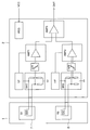
- the circuit block diagram which shows the block configuration of the sensor circuit part of the position detection sensor shown in FIG. FIG.
- FIG. 7 is a circuit block diagram showing another example (part 1) of the block configuration of the sensor circuit section shown in FIG. 6.
- FIG. 7 is a circuit block diagram showing another example (2) of the block configuration of the sensor circuit section shown in FIG. 6.
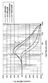
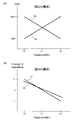
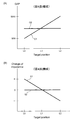
- the relationship diagram of the excitation frequency of a coil and an impedance change rate (A) is explanatory drawing which shows the relationship between the target position and the gap between the 1st and 2nd member of a target, and a coil, (B) is explanatory drawing which shows the relationship between a target position and the impedance change of a coil.
- FIGS. 4A to 4D are diagrams showing examples in which the position detection sensor shown in FIG.
- FIG. 1 is applied to a position detection system for detecting the position of a rod.
- (A) is a figure which shows the example which applied the position detection sensor shown in FIG. 1 to the position detection system which detects the position of a rod, respectively.
- FIGS. 4A to 4D are diagrams showing examples in which the position detection sensor shown in FIG. 1 is applied to a position detection system for detecting the position of a rod. It is a figure which shows the example which applied the position detection sensor shown in FIG.
- (A) is the arrangement
- (B ) Is an arrow view viewed from the direction of arrow V in (A)
- (C) is a partially enlarged view showing the W portion in (A) in an enlarged manner.
- the internal block diagram of the sensor detection part of the position detection sensor shown in FIG. The internal block diagram of the other examples (the 1) of the sensor detection part of the position detection sensor shown in FIG.
- the system block diagram which shows schematic structure of the CVT system in which the belt-type continuously variable transmission (CVT) shown in FIG. 17 is incorporated.
- FIG. 1A is a layout view showing a basic configuration of a position detection system using a position detection sensor according to the present invention
- FIG. It is. 2A is an internal configuration diagram of the sensor detection unit
- FIG. 2B is a bottom view of the sensor detection unit.
- the position detection sensor 10 detects the position (displacement, movement amount, stroke) of a target (detected body) 9 moving in a predetermined direction (arrow X direction).
- the sensor detection unit 1 includes two detection coils (hereinafter simply referred to as coils) 7 and 8, and a sensor circuit unit 2 that performs processing of signals obtained by the sensor detection unit 1, and the like. They are electrically connected.
- the sensor detection unit 1 has a gap so as to be disposed at a position and an orientation facing the outer surface of the target 9 (the outer surface of the second member 4) made of the metal first member 3 and the second member 4 to be detected.
- (Gap) 5 is attached to a housing 6 as a holding member.
- the plurality of coils 7 and 8 built in the sensor detection unit 1 are arranged in parallel to the outer surface of the target 9 (in other words, in a direction perpendicular to the moving direction of the target 9 (arrow X direction)). ing.
- the coils 7 and 8 of the sensor detection unit 1 use separate core members 7a and 8a, and the core members 7a and 8a are wound coils 7b. 8b are wound and integrated with a non-metallic material such as a molding material, and the sensor circuit portion is connected via connecting wires 7c and 8c formed of ends of the winding coils 7b and 8b. 2 is electrically connected.
- the lower surfaces (surfaces on the target 9 side) of the plurality of coils 7 and 8 built in the sensor detection unit 1 are arranged apart by a predetermined distance.
- the plurality of coils 7 and 8 (the lower surface thereof) may be disposed adjacent to each other.
- the same (common) core material (in the illustrated example, a substantially U-shaped core material) 11 is used for each of the coils 7 and 8, and each coil is used as the core material 11.
- the winding coils 7b and 8b of 7 and 8 may be wound.
- the sensor circuit unit 2 has the same number of frequency circuits as the coils of the sensor detection unit 1 so as to generate an excitation frequency corresponding to the number of coils of the sensor detection unit 1 as can be understood by referring to FIG.
- Each frequency circuit generates different frequencies to supply alternating currents of different frequencies to the coils 7 and 8, and has a voltage conversion output circuit corresponding to the impedance of the coils 7 and 8, and the voltage A conversion output circuit converts the impedance change of the coils 7 and 8 into a voltage change (Z / V) and outputs it (details will be described later).
- the sensor circuit unit 2 operates by receiving an external power supply (VCC).
- the sensor detection unit 1 and the sensor circuit unit 2 constituting the position detection sensor 10 are separated from each other, but it is natural that they may be integrated.
- the target 9 disposed so as to face the position detection sensor 10 is an outer surface of the first member 3 made of a single magnetic metal (the sensor detection unit 1 of the position detection sensor 10). ) Side surface) and a structure in which a second member 4 made of a single nonmagnetic metal is superposed, and the outer surface of the second member 4 (on the position detection sensor 10 (the sensor detection unit 1) side).
- the surface on the side opposite to the interface with the first member 3) is disposed so as to face the sensor detection unit 1.
- G1 is the distance from the position immediately below the coil 7 to the first member 3
- G2 is the distance from the position immediately below the coil 8 to the second member 4
- L0 to L1 to L2 are the sensor detection unit 1. The range of movement of the target 9 with respect to the center of is shown.
- both the outer surface of the first member 3 and the outer surface of the second member 4 constituting the target 9 are in the moving direction (arrow X direction) of the target 9.
- the outer surface of the first member 3 and the outer surface of the second member 4 are inclined (inclination angles) opposite to each other with respect to the moving direction (arrow X direction) of the target 9.
- 4B as shown in FIG. 4B, only the outer surface of the first member 3 is inclined with respect to the moving direction (arrow X direction) of the target 9, and the outer surface of the second member 4. May be formed in parallel to the moving direction (arrow X direction) of the target 9 (that is, parallel to the sensor detection unit 1 (coils 7 and 8 thereof)).
- the outer surface of the first member 3 is formed in parallel to the movement direction (arrow X direction) of the target 9 (that is, parallel to the sensor detection unit 1 (coils 7 and 8 thereof)).
- only the outer surface of the second member 4 may be inclined with respect to the moving direction (arrow X direction) of the target 9. 4A and 4B, the sensor circuit unit 2 is omitted.
- FIG. 5 shows an electromagnetic principle configuration for detecting the impedance change of the coils 7 and 8 by the approach or separation of the target 9 (the first member 3 and the second member 4).
- the sensor circuit unit 2 generates an alternating voltage current having a specific frequency in order to excite the coils 7 and 8.
- the sensor circuit unit 2 has a circuit configuration that outputs the impedance change of the coils 7 and 8 as a voltage change.
- the coils 7 and 8 have an impedance value due to the AC voltage current of the sensor circuit unit 2, and generate an alternating magnetic field by the AC voltage current of a specific frequency for exciting the coils 7 and 8 of the sensor circuit unit 2.
- eddy current is generated on the side of the target 9 facing the coils 7 and 8 of the first member 3 and the second member 4.
- a magnetic field that is opposite to the magnetic field direction of the coils 7 and 8 is generated. Due to the interaction between the magnetic field from the coils 7 and 8 and the magnetic field from the first member 3 and the second member 4 of the target 9, the impedance of the coils 7 and 8 further varies.
- the impedance of the coils 7 and 8 varies according to the change in the distance between the target 9 and the coils 7 and 8.
- FIG. 6 is a circuit block diagram showing a block configuration of the sensor circuit section of the position detection sensor shown in FIG. 1 for obtaining the impedance (change) of the coils 7 and 8 described above.
- the sensor circuit unit 2 includes, for each of the coils 7 and 8 provided in the sensor detection unit 1, a bridge circuit BR (BR1, BR2) including an AC voltage / current source F (LF, HF) and coils 7 and 8, and a filter circuit.
- a bridge circuit BR BR1, BR2
- the amplifier circuit includes an amplifier circuit AMP (AMP3) and an internal power supply circuit REG.
- FIG. 6 does not show details of circuits that are attached to the other components.
- the sensor detection unit 1 and the sensor circuit unit 2 may have an integrated configuration in addition to a separate configuration as illustrated, or may be further divided into separate configurations.
- the filter circuit LPF removes components other than the frequency component approximated to the AC voltage / current source LF.
- the coil (S2) 8 shown in FIG. 6 is connected to a predetermined position of the bridge circuit BR2 included in the sensor circuit unit 2.
- the AC voltage / current source HF is connected to the coil (S2) 8 via the bridge circuit BR2.
- the bridge circuit BR2 inputs a change in AC voltage due to a change in impedance of the coil (S2) 8 to the amplifier circuit AMP2 via the filter circuit HPF.
- the amplifier circuit AMP2 rectifies the voltage change of the bridge circuit BR2 into differential amplification and synchronous detection and a DC voltage and inputs the rectified voltage to the amplifier circuit AMP3.
- the filter circuit HPF removes components other than the frequency component approximated to the AC voltage / current source HF.
- the amplifier circuit AMP3 performs differential calculation processing on signals from the bridge circuit BR1 and the bridge circuit BR2 and outputs a DC voltage. As a result, the impedance change of the coils 7 and 8 is output as a voltage change.
- connection location of the coil (S2) 8 to the bridge circuit BR2 may be changed, or as shown in FIG.
- the output logic of the amplifier circuit AMP2 may be inverted.
- FIG. 9 shows the impedance change rate of the coil when the distance between the coil having a specific shape and the metal member constituting the target is changed, and the impedance change rate is shown with the frequency of the alternating voltage applied to the coil as the horizontal axis. It is shown as an axis.
- the case of two types each about a magnetic characteristic metal (SPCC, S45C) and a nonmagnetic characteristic metal (SUS304, A2017) and a total of four types is shown.
- the impedance change rate is large relative to the magnetic material (SPCC, S45C), and in the vicinity of a relatively high frequency HF position (around 100 KHz). Then, the impedance change rate is larger on the negative side than non-magnetic materials (SUS304, A2017).
- a relatively low frequency LF is applied to one coil 7 and a relatively high frequency HF is applied to the other coil 8, whereby a magnetic material (relatively high magnetic property) is produced in the coil 7.
- the influence on the first member 3) can be detected as an impedance change, and the influence on the non-magnetic material (second member 4 having relatively low magnetism) can be detected as the impedance change by the coil 8 and selectively extracted. Note that the frequency applied to the coils 7 and 8 may be changed.
- FIG. 10 to 12 show the target position and the first and second members of the target when a relatively low frequency is applied to the coil (S1) 7 and a relatively high frequency is applied to the coil (S2) 8.
- FIG. 10A is an explanatory diagram showing the relationship between the gaps (distances) between the coils
- FIG. 10B is a diagram showing the relationship between the impedance change of the coils due to the gap between the target position and the target.
- (B) corresponds to the configuration shown in FIG. 1 (A)
- FIGS. 11 (A) and (B) correspond to the configuration shown in FIG. 4 (A)
- FIG. 12 (A) corresponds to the configuration shown in FIG.
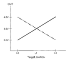
- FIG. 13 is an explanatory diagram showing the relationship between the target position (the position in the moving direction of the target) and the output voltage of the sensor circuit unit.
- the impedance change rates of the coils 7 and 8 due to the gap with the target 9 are as follows. If it has a cross characteristic, as shown in FIG. 13, the position (displacement, movement amount, stroke) of the target (detected body) 9 is detected from the output voltage of the sensor circuit unit 2 obtained by the difference. It becomes possible.
- the output voltage of the sensor circuit unit 2 is shown in FIG. 13 by the combination of the target 9 (the first member 3 and the second member 4) and the processing circuit of the sensor circuit unit 2.
- the logic (dotted line) may be opposite to the relationship indicated by the solid line.
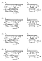
- the rod 29 in the example shown in FIGS. 14A to 14D faces the sensor detection unit 1 of the position detection sensor 10 of the first member 21 having a rectangular cross section (extending in the axial direction) made of a magnetic material.
- a second member 22 having a rectangular cross section made of a non-magnetic material is placed and fixed (for example, fixed by bonding) at a location (opposing surface).
- the portion (facing surface) facing the sensor detection unit 1 of the first member 21 is a surface inclined with respect to the axial direction (the moving direction of the rod 29).
- a surface facing the sensor detection unit 1 is formed on the inclined surface with the same gradient as the inclined surface (that is, the surfaces facing the sensor detection unit 1 of the first member 21 and the second member 22 are parallel to each other).
- the second member 22 (inclined in the same direction) is placed and fixed (see also FIG. 1A).
- the portion (opposing surface) facing the sensor detection unit 1 of the first member 21 is a surface inclined with respect to the axial direction (movement direction of the rod 29).
- a second member 22 having a surface facing the sensor detection unit 1 and a slope opposite to the inclined surface with respect to the axial direction (moving direction of the rod 29) is placed and fixed (see FIG. 4A). See also).
- the portion (opposing surface) facing the sensor detection unit 1 of the first member 21 is a plane parallel to the axial direction (moving direction of the rod 29) (no gradient), and is flat.
- a second member 22 whose surface facing the sensor detection unit 1 is inclined (gradient) with respect to the axial direction (moving direction of the rod 29) is placed and fixed on the surface.
- the portion (opposing surface) facing the sensor detection unit 1 of the first member 21 is a surface inclined (having a gradient) with respect to the axial direction (the moving direction of the rod 29).
- the second member 22 whose surface facing the sensor detection unit 1 is parallel to the axial direction (the moving direction of the rod 29) (no gradient) is mounted and fixed (FIG. 4B). See also).
- the sensor detection unit 1 of the position detection sensor 10 faces the second member 22 disposed at the distal end of the rod 29, and the coils 7 and 8 built in the sensor detection unit 1 are in the moving direction of the rod 29.
- the first member 21 of the rod 29 composed of the first member (magnetic material) 21 and the second member (nonmagnetic material) 22
- the inclined surfaces of the two members 22 operate so that the gap changes with respect to the sensor detection unit 1 (coils 7 and 8 thereof).
- the sensor circuit unit 2 (not shown) outputs a signal (impedance change) detected by the coils 7 and 8 in the sensor detection unit 1 as a voltage signal corresponding to the target position. This makes it possible to detect the position of the rod-shaped rod (object to be detected) 29 (or measure the movement distance).
- the rod 29 when at least one target surface parallel to the moving direction of the rod 29 (without a gradient) is formed, the rod is affected by, for example, external vibration.
- the sensor circuit unit 2 differentially amplifies the parallel target surface having no gradient and the target surface having the gradient, thereby obtaining the vertical direction. The displacement of can be canceled.
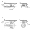
- the rod 39 in the example shown in FIG. 15A is a portion (opposing surface) facing the sensor detection unit 1 of the position detection sensor 10 of the first member 31 having a rectangular cross section (extending in the axial direction) made of a magnetic material. ), The second member 32 having a rectangular cross section made of a nonmagnetic material is placed and fixed.
- a portion (opposing surface) facing the sensor detection unit 1 of the first member 31 is formed in a step shape along the axial direction (moving direction of the rod 39),
- the second member 32 formed so that the surface facing the sensor detection unit 1 is formed stepwise along the axial direction (the movement direction of the rod 39) (similar to the step-like surface). It is fixed.
- the rod 39 in the example shown in FIG. 15B is a portion facing the sensor detection unit 1 of the position detection sensor 10 of the columnar (extending in the axial direction) first member 31 made of a magnetic material.
- the substantially cylindrical second member 32 made of a nonmagnetic material is extrapolated and fixed to the surface).
- the surface (outer peripheral surface) facing the sensor detection unit 1 is in the axial direction (rod) at the location (opposite surface) facing the sensor detection unit 1 of the first member 31.
- the second member 32 formed in a step shape along the movement direction (39) is fixed by extrapolation.
- the output voltage of the sensor circuit unit 2 obtained from the coils 7 and 8 of the sensor detection unit 1 of the position detection sensor 10 based on the rod (target) position. Becomes a stepped shape, and the position of the rod-shaped rod (detected body) 39 can be detected stepwise (stepwise) (or the movement can be measured stepwise).
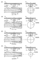
- a rod 49 in the example shown in FIGS. 16A to 16D is a portion facing the sensor detection unit 1 of the position detection sensor 10 of the columnar (extending in the axial direction) first member 41 made of a magnetic material.
- a substantially cylindrical second member 42 made of a nonmagnetic material is extrapolated on the (opposite surface).
- the first member 41 and the second member 42 are a screw part (male screw part) provided at the tip part (the outer periphery thereof) of the first member 41 and a screw part provided at the second member (the inner periphery thereof) ( A female thread portion) is screwed and fixed integrally.
- FIG. 17 is a diagram showing an example in which the position detection sensor shown in FIG. 1 is applied to a position detection system that detects the position of a pulley half of a belt-type continuously variable transmission (CVT), and FIG. FIG. 17B is an arrangement diagram showing a basic configuration, FIG. 17B is an arrow view seen from the direction of arrow V in FIG. 17A, and FIG. 17C is an enlarged view of the W portion in FIG. FIG. In FIG. 17B, the actuator is not shown. In FIG. 17, the sensor circuit portion of the position detection sensor is omitted.
- CVT continuously variable transmission
- the rotation speed of the primary shaft 51a that is the input shaft (drive shaft) is steplessly set.
- the primary shaft 51a and the secondary shaft 51b which are two rotary shafts arranged in parallel with each other, and a primary provided on the primary shaft 51a are transmitted to the secondary shaft 51b which is an output shaft (driven shaft).
- the pulley (drive pulley) 52a, the secondary pulley (driven pulley) 52b provided on the secondary shaft 51b, and the pulley 52a, 52b are spanned between them, and the power of the primary pulley 52a is transmitted to the secondary pulley 52b.
- Each of the pulleys 52a and 52b is composed of a pair of pulley halves, and one of the pair of pulley halves is movably attached in the direction of the axis (rotation axis) of the shafts 51a and 51b.
- the shafts 51a and 51b are provided with actuators 54a and 54b for making the position of the pulley halves variable (that is, moving the pulley halves in conjunction with the axial direction of the shafts 51a and 51b).
- the pulley halves of the pulleys 52a and 52b (the pulleys in which the axial positions of the shafts 51a and 51b are varied by the actuators 54a and 54b).
- a gradient structure composed of the first members 55a and 55b made of the magnetic material and the second members 56a and 56b made of the non-magnetic material (see also FIG. 1A)
- the position detection sensor 10a is provided on the outer side of the pulley half so as to face the outer peripheral surface of the pulley half of each pulley 52a, 52b (the outer peripheral surface of the second members 56a, 56b disposed on the outer side).
- 10b sensor detectors 1a and 1b are attached to the casings 6a and 6b.
- a gradient structure similar to the structure shown in FIG. 1A is applied to the outer peripheral portion of the pulley half of each pulley 52a, 52b.
- a gradient structure similar to the structure shown in B) may be applied.
- the gradient structure and the position detection sensor are applied to the pulley halves of both pulleys 52a and 52b.
- the gradient structure is applied only to the pulley halves of one of the pulleys 52a and 52b. Needless to say, a position detection sensor may be applied.
- each pulley 52a and 52b are arranged side by side (in a straight line) in a direction perpendicular to the pulley halves (moving direction).
- the coils 7a and 8a in the sensor detection unit 1a and the coils 7b and 8b in the sensor detection unit 1b are, for example, as shown in FIG. 19 by first members 55a and 55b and second members 56a and 56b. Outside the pulley half of each configured pulley 52a, 52b, along the rotational direction of the pulley half of each pulley 52a, 52b (in other words, toward the center of rotation of the pulley half of each pulley 52a, 52b) B) may be arranged side by side. Further, as shown in FIG.
- the coils 7a and 8a in the sensor detection unit 1a and the coils 7b and 8b in the sensor detection unit 1b are separated, and the first members 55a and 55b and the second members 56a and 56b are separated.
- the pulley half of each pulley 52a, 52b on the opposite side to the axis (rotation axis) of each shaft 51a, 51b, and at the center of rotation of the pulley half of each pulley 52a, 52b You may arrange
- each pulley 52a, 52b as a target (detected body) when each pulley half moves in the axis (rotation axis) direction of each shaft 51a, 51b. It is possible to accurately detect the position of the pulley halves 52a and 52b without contact (or to accurately measure the movement distance).
- the coils 7a and 8a in the sensor detection unit 1a and the coils 7b and 8b in the sensor detection unit 1b are arranged with the arrangement configuration described based on FIG.
- steps 57 and 58 formed from recesses are provided (particularly, the outer peripheral surfaces of the first members 55a and 55b along the rotational direction of the pulley halves of the pulleys 52a and 52b). And the steps 57 and 58 are provided at different rotational angle positions on the outer peripheral surfaces of the second members 56a and 56b), so that the rotational speed and rotational direction of the pulley halves of the respective pulleys 52a and 52b can be adjusted simultaneously. It also becomes possible to detect.
- FIG. 22 is a system configuration diagram showing a schematic configuration of a CVT system in which the belt type continuously variable transmission (CVT) shown in FIG. 17 is incorporated.
- CVT continuously variable transmission
- the CVT system 100 is mainly for hydraulically driving the positions of the CVT 50 provided with the position detection sensor 10 (10a, 10b) and the pulley halves of the pulleys 52a, 52b of the CVT 50.
- the hydraulic actuator 61, the hydraulic pump 62 for generating hydraulic pressure, the hydraulic valve 63 for opening and closing the valve to supply the hydraulic pressure to the hydraulic actuator 61, the hydraulic pump 62 and the hydraulic valve 63 (opening and closing) are electrically connected.
- a driver 64 for detecting the hydraulic pressure
- a hydraulic pressure detection sensor 65 for detecting the hydraulic pressure supplied to the hydraulic actuator 61
- TCU transmission control unit
- the CVT 50 provided with the position detection sensor 10 (10a, 10b) into the CVT system 100, the positions of the pulley halves of the pulleys 52a and 52b of the CVT 50 are accurately detected and fed back to the TCU 60.
- the CVT system 100 (for example, the driver 64) can be controlled more precisely and efficiently.
- the plurality of coils 7 and 8 are driven at different frequencies, and the impedance change of the plurality of coils 7 and 8 when the detected object moves,
- the position of the detection object By detecting the position of the detection object, it is possible to accurately detect the position (displacement, amount of movement, stroke) of the target in the moving direction even when the target is displaced (rattle) in a direction perpendicular to the moving direction. It becomes.
- the present invention is not limited to the above-described embodiment, and includes various modifications.
- the above-described embodiment has been described in detail for easy understanding of the present invention, and is not necessarily limited to one having all the configurations described.
- a part of the configuration of an embodiment can be replaced with the configuration of another embodiment, and the configuration of another embodiment can be added to the configuration of an embodiment.
- control lines and information lines indicate what is considered necessary for the explanation, and not all the control lines and information lines on the product are necessarily shown. Actually, it may be considered that almost all the components are connected to each other.
- Sensor detection unit 2 Sensor circuit unit 3: First member (magnetic material) 4: Second member (non-magnetic material) 5: Air gap 6: Housing 7: Coil 8: Coil 9: Target (object to be detected) 10: Position detection sensors 21, 31, 41: First member (magnetic material) 22, 32, 42: second member (nonmagnetic material) 29, 39, 49: Rod (target) 50: Belt type continuously variable transmission (CVT) 51a: Primary shaft 51b: Secondary shaft 52a: Primary pulley 52b: Secondary pulley 53: Belt 54a: Actuator 54b: Actuator 55a: First member 55b of primary pulley: First member 56a of secondary pulley: Second member 56b of primary pulley : Second member 57, 58 of secondary pulley: Step 60: Control unit for transmission control (TCU) 61: Hydraulic actuator 62: Hydraulic pump 63: Hydraulic valve 64: Driver 65: Hydraulic detection sensor 100: CVT system
Landscapes
- Physics & Mathematics (AREA)
- General Physics & Mathematics (AREA)
- Measurement Of Length, Angles, Or The Like Using Electric Or Magnetic Means (AREA)
- Transmissions By Endless Flexible Members (AREA)
Abstract
ターゲット(9)が移動方向に垂直な方向で変位する(がたつく)場合でも、ターゲットの移動方向における位置を精度良く検出することのできる小型の位置検出センサ、該位置検出センサを用いた位置検出システム、及び該位置検出センサを備えたベルト式無段変速機を提供する。第1部材(3)の外面に該第1部材(3)より磁性の低い第2部材(4)が配置され、前記第1部材(3)の外面及び前記第2部材(4)の外面の少なくとも一方が前記所定方向に対して傾斜している若しくは前記所定方向に沿って階段状に形成されているターゲット(9)の前記第2部材(4)の外面に対面するように配置され、異なる周波数で駆動する複数のコイル(7,8)を有し、被検出体が移動するときの前記複数のコイル(7,8)のインピーダンス変化から、前記ターゲット(9)の位置を検出する。
Description
本発明は、位置検出センサに係り、特に、所定方向に移動する被検出体(検出対象となる構造体)の位置を検出する非接触式の位置検出センサ、該位置検出センサを用いた位置検出システム、及び該位置検出センサを備えたベルト式無段変速機に関する。
移動するターゲット(被検出体)の位置(変位、移動量、ストローク)を検出する位置検出センサは、ターゲットまでの距離を計測する手段を有し、そのターゲットが移動して変位した物理量に対応した情報を出力することで、そのターゲットの位置を検出するものである。
前記した位置検出センサとしては、ターゲットに直接接触させて前記距離を計測するものと、非接触で前記距離を計測するものとが広く知られているが、使用される環境により、非接触でターゲットを検出しなくてはならない場合が有る。
このように非接触で前記距離を計測してターゲットの位置を検出するものとしては、磁石を用いた方式、静電容量式、光学式、超音波式、渦電流式などのセンサがあるが、例えば磁石を用いた方式や光学式などのセンサは、ターゲットが配置されている周囲環境条件により、機械用オイル油中や異物コンタミの影響によって計測が不利な場合があるといった問題や、ターゲットの動作(移動)方向に対向して取り付けることが難しい場合があるといった問題がある。
それに対し、渦電流式のセンサは、ターゲットの測定面に磁界を付与し、その測定面に生じた渦電流によるインピーダンス変化をセンサ内のコイルで求めることにより、ターゲットの移動に応じて変化する測定面とセンサとの間の距離を検出するものであり、センサ自体の構成が他のタイプのセンサと比べてコンパクトであり、センサ自体の取り付けも容易である。
前述のような渦電流式の位置検出センサに関する従来技術として、特許文献1、2に所載の技術が既に知られている。
特許文献1に開示されているベルト式無段変速機(CVT:Continuously Variable Transmission)は、可動シーブの外周端部に形成された測定面と、前記外周端部に離隔して設けられた変位センサであって、前記測定面と当該変位センサとの間の距離を測定する変位センサと、を有し、前記測定面が、可動シーブが軸方向に移動するにつれて、前記測定面と前記変位センサとの間の距離が変化するように形成されているものである。
特許文献2に開示されている軸方向移動量計測システムは、回転体の回転軸に同心に設けられた円盤状のフランジ部と、前記フランジ部の一方の外周縁に対向して設置された第1の渦電流センサと、前記フランジ部の他方の外周縁に対向して設置された第2の渦電流センサと、前記第1の渦電流センサの出力値および前記第2の渦電流センサの出力値に基づいて前記回転体の軸方向の移動量を算出する移動量算出手段とを備えているものである。
特許文献1、2に開示されている従来技術によれば、例えば、磁石等を使用せずに、機械用オイル油中にターゲットが置かれてもそれに影響されずに、非接触で前記距離を計測してターゲットの位置を検出することができる。しかし、特許文献1、2に所載の従来技術では、ターゲットが移動方向に垂直な方向で変位する(がたつく)場合(例えば、特許文献1では、ターゲットとなる測定面を有する可動シーブがシャフトの軸方向への移動に伴って当該シャフトに対してがたつく場合、特許文献2では、ターゲットとなるフランジ部を有する回転体が回転軸の軸方向への移動に伴って当該回転軸に対してがたつく場合)、前記距離を精緻に計測することができなくなる。また、特許文献2に所載の従来技術では、計測精度を確保するために、2つの渦電流センサを回転体の軸方向で離間して配置する必要があるといった問題もある。
本発明は、前記課題に鑑みてなされたものであって、その目的とするところは、例えばターゲットが移動方向に垂直な方向で変位する(がたつく)場合でも、ターゲットの移動方向における位置を精度良く検出することのできる小型の位置検出センサ、該位置検出センサを用いた位置検出システム、及び該位置検出センサを備えたベルト式無段変速機を提供することにある。
上記する課題を解決するために、本発明に係る位置検出センサは、所定方向に移動自在となっている被検出体であって、第1部材の外面に該第1部材より磁性の低い第2部材が配置され、前記第1部材の外面及び前記第2部材の外面の少なくとも一方が前記所定方向に対して傾斜している若しくは前記所定方向に沿って階段状に形成されている被検出体の位置を検出する位置検出センサであって、異なる周波数で駆動する複数のコイルを有し、前記複数のコイルが前記被検出体の前記第2部材の外面に対面するように配置された状態で前記被検出体が移動するときの前記複数のコイルのインピーダンス変化から、前記被検出体の位置を検出することを特徴としている。
本発明によれば、複数のコイルを異なる周波数で駆動させ、被検出体が移動するときの前記複数のコイルのインピーダンス変化から、前記被検出体の(前記所定方向における)位置を検出することで、例えばターゲットが移動方向に垂直な方向で変位する(がたつく)場合でも、ターゲットの移動方向における位置を精度良く検出することが可能となる。
上記した以外の課題、構成及び効果は、以下の実施形態の説明により明らかにされる。
以下、本発明の実施形態について図面を参照して説明する。
<位置検出センサ及び位置検出システムの構成並びに動作>
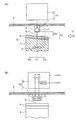
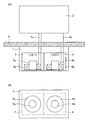
図1(A)は、本発明に係る位置検出センサを用いた位置検出システムの基本構成を示す配置図、図1(B)は、図1(A)の矢印U方向から視た矢視図である。また、図2(A)は、センサ検出部の内部構成図、図2(B)は、センサ検出部の下面図である。
図1(A)は、本発明に係る位置検出センサを用いた位置検出システムの基本構成を示す配置図、図1(B)は、図1(A)の矢印U方向から視た矢視図である。また、図2(A)は、センサ検出部の内部構成図、図2(B)は、センサ検出部の下面図である。
図示するように、位置検出センサ10は、所定方向(矢印X方向)に移動するターゲット(被検出体)9の位置(変位、移動量、ストローク)を検出するもので、基本的に、複数(図示例では、2個)の検出コイル(以下、単にコイルという)7及び8を有するセンサ検出部1と、センサ検出部1により得られる信号の処理等を行うセンサ回路部2とで構成され、それらが電気的に接続されている。
センサ検出部1は、検出対象となる金属製の第1部材3及び第2部材4からなるターゲット9の外面(第2部材4の外面)に対面した位置及び向きに配置されるように、空隙(ギャップ)5を挟んで保持部材としての筐体6に取り付いている。また、センサ検出部1に内蔵される複数のコイル7、8は、ターゲット9の外面に対して平行(言い換えれば、ターゲット9の移動方向(矢印X方向)に垂直な方向)に並んで配置されている。
より詳しくは、前記センサ検出部1の各コイル7、8は、図2(A)に示されるように、別個のコア材7a、8aを使用し、そのコア材7a、8aに巻線コイル7b、8bが巻回されて構成されており、それらがモールド材などの非金属材で一体化されるとともに、巻線コイル7b、8bの端部からなる接続線7c、8cを介してセンサ回路部2に電気的に接続されている。なお、図2(B)等に示す例では、センサ検出部1に内蔵される複数のコイル7、8の下面(ターゲット9側の面)は、所定距離だけ離れて配置されているが、当該複数のコイル7、8(の下面)は、隣接して配置しても良い。
また、図3に示されるように、各コイル7、8で同一の(共通の)コア材(図示例では、略コの字状のコア材)11を使用し、そのコア材11に各コイル7、8の巻線コイル7b、8bを巻回して構成しても良いことは勿論である。
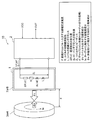
一方、センサ回路部2は、図1(B)を参照すればよく分かるように、センサ検出部1のコイル数に対応した励磁周波数を発生すべく、センサ検出部1のコイルと同数の周波数回路を有し、各々の周波数回路が異なる周波数を発生させて各コイル7、8に異なる周波数の交流電流を供給するとともに、コイル7、8のインピーダンスに対応した電圧変換出力回路を有し、その電圧変換出力回路がコイル7、8のインピーダンス変化を電圧変化に変換(Z/V)して出力するようになっている(詳細は後述)。なお、このセンサ回路部2は、外部からの電源(VCC)供給を受けて動作するようになっている。
なお、図示例では、位置検出センサ10を構成するセンサ検出部1とセンサ回路部2が分離して構成されているが、一体化しても良いことは当然である。
前記位置検出センサ10(のセンサ検出部1)に対面するように配置されるターゲット9は、単一の磁性金属で構成された第1部材3の外面(位置検出センサ10(のセンサ検出部1)側の面)に単一の非磁性金属で構成された第2部材4を重ね合わせた構造を有し、その第2部材4の外面(位置検出センサ10(のセンサ検出部1)側の面であって、第1部材3との界面とは反対側の面)がセンサ検出部1に対面するように配置されている。
また、ここでは、図1(A)、(B)を参照すればよく分かるように、ターゲット9を構成する第1部材3の外面(ギャップ面ともいう)及び第2部材4の外面(ギャップ面ともいう)の双方が前記ターゲット9の移動方向(矢印X方向)に対して同じ勾配(傾斜角)で傾斜しており、ターゲット9全体がセンサ検出部1に対して(矢印X方向に)移動すると、センサ検出部1の先端から垂直な方向でのターゲット9までのギャップ5が変化するようになっており、そのギャップ5の大きさに対応した信号が前記センサ回路部2から出力される。
図1(A)において、G1は、コイル7の直下から第1部材3までの距離、G2は、コイル8の直下から第2部材4までの距離、L0~L1~L2は、センサ検出部1の中央に対するターゲット9の移動範囲を表わしている。
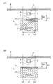
なお、図1(A)、(B)に示す例では、ターゲット9を構成する第1部材3の外面及び第2部材4の外面の双方が前記ターゲット9の移動方向(矢印X方向)に対して同じ勾配で傾斜しているが(言い換えれば、第1部材3の外面と第2部材4の外面とが平行であるが)、第1部材3の外面及び第2部材4の外面は、少なくとも一方が前記ターゲット9の移動方向(矢印X方向)に対して傾斜している若しくは前記ターゲット9の移動方向(矢印X方向)に沿って階段状に形成されていれば良い。例えば、図4(A)に示されるように、第1部材3の外面と第2部材4の外面を、前記ターゲット9の移動方向(矢印X方向)に対して互いに反対の勾配(傾斜角)で傾斜させても良いし、図4(B)に示されるように、第1部材3の外面のみを前記ターゲット9の移動方向(矢印X方向)に対して傾斜させ、第2部材4の外面を、前記ターゲット9の移動方向(矢印X方向)に平行(つまり、センサ検出部1(のコイル7、8)に対して平行)に形成しても良い。また、図示は省略するが、第1部材3の外面を、前記ターゲット9の移動方向(矢印X方向)に平行(つまり、センサ検出部1(のコイル7、8)に対して平行)に形成し、第2部材4の外面のみを前記ターゲット9の移動方向(矢印X方向)に対して傾斜させても良い。なお、図4(A)、(B)では、センサ回路部2が省略されている。
図5は、ターゲット9(の第1部材3及び第2部材4)の接近又は離間によりコイル7、8のインピーダンス変化を検出するための電磁気的な原理構成を示したものである。前述のように、センサ回路部2は、コイル7、8へ励磁するため、特定周波数の交流電圧電流を発生する。また、センサ回路部2は、コイル7、8のインピーダンス変化を電圧変化として出力する回路構成を有する。
コイル7、8は、センサ回路部2の交流電圧電流によりインピーダンス値を有し、センサ回路部2のコイル7、8へ励磁するための特定周波数の交流電圧電流により交番した磁界を発生する。一方で、コイル7、8にターゲット9の第1部材3及び第2部材4が接近すると、ターゲット9の第1部材3及び第2部材4のコイル7、8に面した側に渦電流が発生し、コイル7、8の磁界方向に反した磁界が発生する。コイル7、8からの磁界とターゲット9の第1部材3及び第2部材4からの磁界の相互作用により、コイル7、8のインピーダンスは更に変動する。また、このコイル7、8のインピーダンスは、ターゲット9とコイル7、8間の距離の変化に応じて変動する。
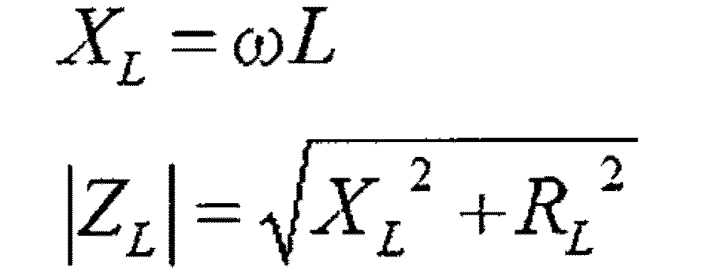
なお、前記したコイル7、8のインピーダンスZLは、周波数をωとして、以下の数式により求まることが知られている。
[数1]
[数1]
図6は、前記したコイル7、8のインピーダンス(変化)を求めるための、図1に示す位置検出センサのセンサ回路部のブロック構成を示す回路ブロック図である。
センサ回路部2は、センサ検出部1に設けられた各コイル7、8に対し、交流電圧電流源F(LF、HF)とコイル7、8を含むブリッジ回路BR(BR1、BR2)とフィルタ回路PF(LPF、HPF)と増幅回路AMP(AMP1、AMP2)とを有するとともに、増幅回路AMP(AMP3)と内部電源回路REGとを備える。なお、図6では、他に付属して構成する回路の詳細は図示していない。また、センサ検出部1とセンサ回路部2とは、図示するような別体構成のほか、一体構成としても良いし、更に分割して別体構成としても良い。
図6に示す検知コイル(S1)7は、センサ回路部2に含まれるブリッジ回路BR1の所定の位置に接続される。また、交流電圧電流源LFは、ブリッジ回路BR1を経由してコイル(S1)7に接続される。ブリッジ回路BR1は、コイル(S1)7のインピーダンス変化による交流電圧の変化をフィルタ回路LPFを経由して増幅回路AMP1に入力する。増幅回路AMP1は、ブリッジ回路BR1の電圧変化を差動増幅及び同期検波と直流電圧に整流して増幅回路AMP3に入力する。ここで、フィルタ回路LPFは、交流電圧電流源LFに近似した周波数成分以外を除去する。
同様に、図6に示すコイル(S2)8は、センサ回路部2に含まれるブリッジ回路BR2の所定の位置に接続される。また、交流電圧電流源HFは、ブリッジ回路BR2を経由してコイル(S2)8に接続される。ブリッジ回路BR2は、コイル(S2)8のインピーダンス変化による交流電圧の変化をフィルタ回路HPFを経由して増幅回路AMP2に入力する。増幅回路AMP2は、ブリッジ回路BR2の電圧変化を差動増幅及び同期検波と直流電圧に整流して増幅回路AMP3に入力する。ここで、フィルタ回路HPFは、交流電圧電流源HFに近似した周波数成分以外を除去する。
増幅回路AMP3は、ブリッジ回路BR1とブリッジ回路BR2からの信号を差動計算処理して直流電圧を出力する。これにより、前記したコイル7、8のインピーダンス変化が電圧変化として出力される。
なお、センサ回路部2において、例えば、図7に示すように、コイル(S2)8のブリッジ回路BR2への接続箇所を変更しても良いし、図8に示すように、(図6に示す形態に対して)増幅回路AMP2の出力論理を反転させても良い。
図9は、特定形状のコイルとターゲットを構成する金属部材間の距離を変化させたときのコイルのインピーダンス変化率を、コイルに印加する交流電圧電流の周波数を横軸に、インピーダンス変化率を縦軸にして示したものである。なお、図9では、磁性特性金属(SPCC、S45C)と非磁性特性金属(SUS304、A2017)についてそれぞれ2種類、合計4種類の場合を示している。
図9に示されるように、相対的に低い周波数LF位置付近(10KHz付近)では、磁性材(SPCC、S45C)に対してインピーダンス変化率が大きく、相対的に高い周波数HF位置付近(100KHz付近)では、非磁性材(SUS304、A2017)に対してインピーダンス変化率がマイナス側に大きい。このことを利用し、相対的に低い周波数LFを一方のコイル7に印加し、相対的に高い周波数HFを他方のコイル8に印加することにより、コイル7で磁性材(相対的に磁性の高い第1部材3)に対する影響をインピーダンス変化として検出でき、コイル8で非磁性材(相対的に磁性の低い第2部材4)に対する影響をインピーダンス変化として検出して選択的に抽出することができる。なお、コイル7、8に適用する周波数を変化させても良い。
図10~図12は、相対的に低い周波数をコイル(S1)7に印加し、相対的に高い周波数をコイル(S2)8に印加したときの、ターゲット位置とターゲットの第1及び第2部材-コイル間のギャップ(距離)の関係を示す説明図(A)、及び、ターゲット位置とターゲットとのギャップによるコイルのインピーダンス変化の関係を示す説明図(B)であり、図10(A)、(B)は、図1(A)に示される構成に対応したもの、図11(A)、(B)は、図4(A)に示される構成に対応したもの、図12(A)、(B)は、図4(B)に示される構成に対応したものである。また、図13は、ターゲット位置(ターゲットの移動方向の位置)とセンサ回路部の出力電圧の関係を示す説明図である。
図10(B)、図11(B)、図12(B)に示すように、ターゲット9(の第1部材3及び第2部材4)とのギャップによる各コイル7、8のインピーダンス変化率がクロス特性を有していれば、図13に示すように、その差分で得られるセンサ回路部2の出力電圧から、ターゲット(被検出体)9の位置(変位、移動量、ストローク)を検出することが可能となる。
なお、図13に実線で示す例のほかに、ターゲット9(の第1部材3及び第2部材4)とセンサ回路部2の処理回路の組み合わせにより、センサ回路部2の出力電圧を、図13に実線で示す関係とは逆の論理(点線)にしても良い。
<位置検出センサ及び位置検出システムの適用例(その1)>
次に、図14~図16を参照して、図1に示す位置検出センサを、軸線方向に移動自在とされている棒状のロッド(被検出体)の位置を検出(あるいは、移動距離を計測)する位置検出システムに適用した例について具体的に説明する。
次に、図14~図16を参照して、図1に示す位置検出センサを、軸線方向に移動自在とされている棒状のロッド(被検出体)の位置を検出(あるいは、移動距離を計測)する位置検出システムに適用した例について具体的に説明する。
図14(A)~(D)に示す例におけるロッド29は、磁性材で構成された断面矩形状の(軸線方向に延びる)第1部材21の位置検出センサ10のセンサ検出部1に対面する箇所(対向面)に、非磁性材で構成された断面矩形状の第2部材22が載置固定(例えば、張り合わせにより固定)されて構成されている。
詳細には、図14(A)に示す例では、第1部材21のセンサ検出部1に対面する箇所(対向面)を軸線方向(ロッド29の移動方向)に対して傾斜した面とし、その傾斜面に、センサ検出部1に対面する面が前記傾斜面と同一の勾配で形成された(つまり、第1部材21と第2部材22のセンサ検出部1に対面する面が平行であって、同一方向に傾斜した)第2部材22が載置固定されている(図1(A)も併せて参照)。
図14(B)に示す例では、第1部材21のセンサ検出部1に対面する箇所(対向面)を軸線方向(ロッド29の移動方向)に対して傾斜した面とし、その傾斜面に、センサ検出部1に対面する面が前記傾斜面と軸線方向(ロッド29の移動方向)に対して反対の勾配で形成された第2部材22が載置固定されている(図4(A)も併せて参照)。
図14(C)に示す例では、第1部材21のセンサ検出部1に対面する箇所(対向面)を軸線方向(ロッド29の移動方向)に平行な(勾配の無い)面とし、その平坦面に、センサ検出部1に対面する面が軸線方向(ロッド29の移動方向)に対して傾斜した(勾配の有る)第2部材22が載置固定されている。
図14(D)に示す例では、第1部材21のセンサ検出部1に対面する箇所(対向面)を軸線方向(ロッド29の移動方向)に対して傾斜した(勾配の有る)面とし、その傾斜面に、センサ検出部1に対面する面が軸線方向(ロッド29の移動方向)に平行とされた(勾配の無い)第2部材22が載置固定されている(図4(B)も併せて参照)。
位置検出センサ10のセンサ検出部1は、ロッド29の先端部に配置された第2部材22に対面し、且つ、センサ検出部1に内蔵されたコイル7、8がロッド29の移動方向に対して垂直な方向に並んで配設されるように、筐体6に配置されている。
ターゲットとしてのロッド29が移動方向(矢印X方向)に移動した場合、第1部材(磁性材)21と第2部材(非磁性材)22で構成されたロッド29の前記第1部材21と第2部材22の傾斜面は、センサ検出部1(のコイル7、8)に対してギャップが変化するように動作する。前述のように、不図示のセンサ回路部2は、センサ検出部1内のコイル7、8で検知した信号(インピーダンス変化)をターゲット位置に対応した電圧信号として出力する。これにより、棒状のロッド(被検出体)29の位置を検出(あるいは、移動距離を計測)することが可能となる。
なお、図14(C)及び図14(D)に示すように、ロッド29の移動方向に平行な(勾配の無い)ターゲット面を少なくとも一つ構成すると、例えば外部からの振動などの影響でロッド29(ターゲット)全体が移動方向に対して垂直な方向に変位する場合、勾配の無い平行なターゲット面と勾配の有るターゲット面とをセンサ回路部2によって差動増幅することにより、前記垂直な方向の変位をキャンセルすることができる。
図15(A)に示す例におけるロッド39は、磁性材で構成された断面矩形状の(軸線方向に延びる)第1部材31の位置検出センサ10のセンサ検出部1に対面する箇所(対向面)に、非磁性材で構成された断面矩形状の第2部材32が載置固定されて構成されている。
詳細には、図15(A)に示す例では、第1部材31のセンサ検出部1に対面する箇所(対向面)を軸線方向(ロッド39の移動方向)に沿って階段状に形成し、その階段状の面に、センサ検出部1に対面する面が(前記階段状の面と同様に)軸線方向(ロッド39の移動方向)に沿って階段状に形成された第2部材32が載置固定されている。
また、図15(B)に示す例におけるロッド39は、磁性材で構成された円柱状の(軸線方向に延びる)第1部材31の位置検出センサ10のセンサ検出部1に対面する箇所(対向面)に、非磁性材で構成された略円筒状の第2部材32が外挿固定されて構成されている。
詳細には、図15(B)に示す例では、第1部材31のセンサ検出部1に対面する箇所(対向面)に、センサ検出部1に対面する面(外周面)が軸線方向(ロッド39の移動方向)に沿って階段状に形成された第2部材32が外挿固定されている。
図15(A)及び図15(B)に示す例では、ロッド(ターゲット)位置による位置検知センサ10のセンサ検出部1のコイル7、8から得られるセンサ回路部2(不図示)の出力電圧が階段状になり、棒状のロッド(被検出体)39の位置を階段状に(段階的に)検出(あるいは、移動を階段状に計測)することが可能となる。
また、図15(B)に示す例では、ロッド39が軸線周りで回転した場合でも、そのロッド39の位置を確実に検出することが可能となる。
図16(A)~(D)に示す例におけるロッド49は、磁性材で構成された円柱状の(軸線方向に延びる)第1部材41の位置検出センサ10のセンサ検出部1に対面する箇所(対向面)に、非磁性材で構成された略円筒状の第2部材42が外挿されて構成されている。第1部材41と第2部材42とは、第1部材41の先端部(の外周)に設けられたネジ部(雄ネジ部)と第2部材(の内周)に設けられたネジ部(雌ネジ部)とが螺着されて一体的に固定されている。
なお、図16(A)~(D)に示す例の第1部材41と第2部材42の外周面(ターゲット面)の勾配関係は、図14(A)~(D)に基づき説明した例の勾配関係と同様であるので、ここでは、その詳細な説明は省略する。
前述したように、図16(A)~(D)に示す例でも、棒状のロッド(被検出体)49の位置を検出(あるいは、移動距離を計測)することが可能となる。特に、ロッド49が軸線周りで回転した場合でも、そのロッド49の位置を確実に検出することが可能となる。
<位置検出センサ及び位置検出システムの適用例(その2)>
次に、図17~図22を参照して、図1に示す位置検出センサを、車両を駆動する原動機に組み込まれて変速比を無段階で変化させるベルト式無段変速機(CVT)のプーリ半体(プライマリシャフトに設けられたプライマリプーリ(駆動側プーリ)のプーリ半体、もしくは、セカンダリシャフトに設けられたセカンダリプーリ(従動側プーリ)のプーリ半体)(被検出体)の位置を検出する位置検出システムに適用した例について具体的に説明する。
次に、図17~図22を参照して、図1に示す位置検出センサを、車両を駆動する原動機に組み込まれて変速比を無段階で変化させるベルト式無段変速機(CVT)のプーリ半体(プライマリシャフトに設けられたプライマリプーリ(駆動側プーリ)のプーリ半体、もしくは、セカンダリシャフトに設けられたセカンダリプーリ(従動側プーリ)のプーリ半体)(被検出体)の位置を検出する位置検出システムに適用した例について具体的に説明する。
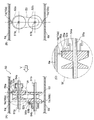
図17は、図1に示す位置検出センサをベルト式無段変速機(CVT)のプーリ半体の位置を検出する位置検出システムに適用した例を示す図であり、図17(A)は、基本構成を示す配置図、図17(B)は、図17(A)の矢印V方向から視た矢視図、図17(C)は、図17(A)のW部を拡大して示す一部拡大図である。なお、図17(B)において、アクチュエータは図示が省略されている。また、図17においては、位置検出センサのセンサ回路部が省略されている。
CVT50自体の構成は一般に知られているので、ここではその詳細説明は割愛するが、図17に示すように、基本的に、入力軸(駆動軸)であるプライマリシャフト51aの回転速度を無段階に変速して出力軸(被駆動軸)であるセカンダリシャフト51bに伝達すべく、互いに平行に配置された2つの回転シャフトであるプライマリシャフト51a及びセカンダリシャフト51bと、プライマリシャフト51aに設けられたプライマリプーリ(駆動側プーリ)52aと、セカンダリシャフト51bに設けられたセカンダリプーリ(従動側プーリ)52bと、これらのプーリ52a、52bの間に掛け渡され、プライマリプーリ52aの動力をセカンダリプーリ52bに伝達する金属製のベルト53とを有する。各プーリ52a、52bは、それぞれが一対のプーリ半体で構成されるとともに、一対のプーリ半体の一方が、各シャフト51a、51bの軸線(回転軸線)方向に移動自在に取り付けられている。各シャフト51a、51bには、前記プーリ半体の位置を可変とする(つまり、前記プーリ半体を各シャフト51a、51bの軸線方向に連動して移動させる)ためのアクチュエータ54a、54bが配設されている。
また、図17(A)、(C)を参照すればよく分かるように、各プーリ52a、52bのプーリ半体(アクチュエータ54a、54bによって各シャフト51a、51bにおける軸線方向の位置が可変されるプーリ半体)の外周部分には、前述した磁性材からなる第1部材55a、55bと非磁性材からなる第2部材56a、56bで構成された勾配構造(図1(A)も併せて参照)が設けられ、その各プーリ52a、52bのプーリ半体の外周面(外側に配置された第2部材56a、56bの外周面)に対向するように、当該プーリ半体の外側に位置検出センサ10a、10bのセンサ検出部1a、1bが筐体6a、6bに対して取り付けられている。
なお、本例では、各プーリ52a、52bのプーリ半体の外周部分に、図1(A)に示される構造と同様の勾配構造が適用されているが、例えば、図4(A)、(B)等に示される構造と同様の勾配構造を適用しても良いことは勿論である。また、本例では、双方のプーリ52a、52bのプーリ半体に、前記勾配構造及び位置検出センサを適用しているが、プーリ52a、52bの一方のプーリのプーリ半体のみに、前記勾配構造及び位置検出センサを適用しても良いことは言うまでも無い。
また、ここでは、位置検出センサ10aのセンサ検出部1aに内蔵されたコイル7a、8aや位置検出センサ10bのセンサ検出部1bに内蔵されたコイル7b、8bは、図18を参照すればよく分かるように、第1部材55a、55bと第2部材56a、56bで構成した各プーリ52a、52bのプーリ半体の外側で、各シャフト51a、51bの軸線(回転軸線)方向に(つまり、各プーリ52a、52bのプーリ半体の移動方向)に垂直な方向に(直線状に)並んで配設されている。
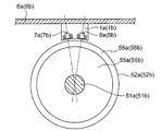
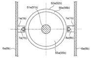
ただし、前記したセンサ検出部1a内のコイル7a、8aやセンサ検出部1b内のコイル7b、8bは、例えば、図19に示すように、第1部材55a、55bと第2部材56a、56bで構成した各プーリ52a、52bのプーリ半体の外側で、各プーリ52a、52bのプーリ半体の回転方向に沿うように(言い換えれば、各プーリ52a、52bのプーリ半体の回転中心に向かうように)並んで配設しても良い。また、図20に示すように、前記したセンサ検出部1a内のコイル7a、8aやセンサ検出部1b内のコイル7b、8bをそれぞれ分離し、第1部材55a、55bと第2部材56a、56bで構成した各プーリ52a、52bのプーリ半体の外側で、各シャフト51a、51bの軸線(回転軸線)に対して反対側などに、且つ、各プーリ52a、52bのプーリ半体の回転中心に向かうように配設しても良い。
かかる構成とすることで、前述したように、ターゲット(被検出体)としての各プーリ52a、52bのプーリ半体が各シャフト51a、51bの軸線(回転軸線)方向で移動したときの当該各プーリ52a、52bのプーリ半体の位置を非接触で精度良く検出(あるいは、移動距離を精度良く計測)することが可能となる。
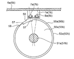
また、例えば、図21に示すように、図19に基づき説明した配置構成でセンサ検出部1a内のコイル7a、8aやセンサ検出部1b内のコイル7b、8bを配置するとともに、磁性材からなる第1部材55a、55bの外周面や非磁性材からなる第2部材56a、56bの外周面に、各プーリ52a、52bのプーリ半体の回転方向に所定長さを有する凹部もしくは凸部(図21に示す例では、凹部(凹状スリット))から形成される段差57、58を設ける(特に、各プーリ52a、52bのプーリ半体の回転方向に沿って、第1部材55a、55bの外周面と第2部材56a、56bの外周面とで異なる回転角度の位置に、前記段差57、58を設ける)ことにより、各プーリ52a、52bのプーリ半体の回転数や回転方向を同時に検出することも可能となる。
図22は、図17に示すベルト式無段変速機(CVT)が組み込まれるCVTシステムの概略構成を示すシステム構成図である。
図示するように、CVTシステム100は、主に、前記した位置検出センサ10(10a、10b)が配備されたCVT50と、CVT50の各プーリ52a、52bのプーリ半体の位置を油圧駆動するための油圧アクチュエータ61と、油圧を発生させるための油圧ポンプ62と、バルブを開閉して油圧を油圧アクチュエータ61に供給するための油圧バルブ63と、油圧ポンプ62及び油圧バルブ63(の開閉)を電気的に駆動するドライバ64と、油圧アクチュエータ61に供給される油圧を検知するための油圧検知センサ65と、本CVTシステム100を制御するトランスミッション制御用コントロールユニット(TCU:Transmission Control Unit)60とを備える。
前記した位置検出センサ10(10a、10b)が配備されたCVT50を本CVTシステム100に組み込むことにより、CVT50の各プーリ52a、52bのプーリ半体の位置を精度良く検出してTCU60にフィードバックすることができ、本CVTシステム100(例えば、そのドライバ64)をより精緻に且つ効率良く制御することが可能となる。
以上の説明から分かるように、本実施形態によれば、複数のコイル7、8を異なる周波数で駆動させ、被検出体が移動するときの前記複数のコイル7、8のインピーダンス変化から、前記被検出体の位置を検出することで、例えばターゲットが移動方向に垂直な方向で変位する(がたつく)場合でも、ターゲットの移動方向における位置(変位、移動量、ストローク)を精度良く検出することが可能となる。
なお、本発明は上記した実施形態に限定されるものではなく、様々な変形形態が含まれる。例えば、上記した実施形態は本発明を分かりやすく説明するために詳細に説明したものであり、必ずしも説明した全ての構成を備えるものに限定されるものではない。また、ある実施形態の構成の一部を他の実施形態の構成に置き換えることが可能であり、また、ある実施形態の構成に他の実施形態の構成を加えることも可能である。また、各実施形態の構成の一部について、他の構成の追加・削除・置換をすることが可能である。
また、制御線や情報線は説明上必要と考えられるものを示しており、製品上必ずしも全ての制御線や情報線を示しているとは限らない。実際には殆ど全ての構成が相互に接続されていると考えてもよい。
1:センサ検出部
2:センサ回路部
3:第1部材(磁性材)
4:第2部材(非磁性材)
5:空隙
6:筐体
7:コイル
8:コイル
9:ターゲット(被検出体)
10:位置検出センサ
21、31、41:第1部材(磁性材)
22、32、42:第2部材(非磁性材)
29、39、49:ロッド(ターゲット)
50:ベルト式無段変速機(CVT)
51a:プライマリシャフト
51b:セカンダリシャフト
52a:プライマリプーリ
52b:セカンダリプーリ
53:ベルト
54a:アクチュエータ
54b:アクチュエータ
55a:プライマリプーリの第1部材
55b:セカンダリプーリの第1部材
56a:プライマリプーリの第2部材
56b:セカンダリプーリの第2部材
57、58:段差
60:トランスミッション制御用コントロールユニット(TCU)
61:油圧アクチュエータ
62:油圧ポンプ
63:油圧バルブ
64:ドライバ
65:油圧検知センサ
100:CVTシステム
Claims (14)
- 所定方向に移動自在となっている被検出体であって、第1部材の外面に該第1部材より磁性の低い第2部材が配置され、前記第1部材の外面及び前記第2部材の外面の少なくとも一方が前記所定方向に対して傾斜している若しくは前記所定方向に沿って階段状に形成されている被検出体の位置を検出する位置検出センサであって、
異なる周波数で駆動する複数のコイルを有し、
前記複数のコイルが前記被検出体の前記第2部材の外面に対面するように配置された状態で前記被検出体が移動するときの前記複数のコイルのインピーダンス変化から、前記被検出体の位置を検出することを特徴とする位置検出センサ。 - 前記第1部材が磁性材で構成され、前記第2部材が非磁性材で構成されていることを特徴とする請求項1に記載の位置検出センサ。
- 前記複数のコイルは、前記所定方向に垂直な方向に並んで配設されていることを特徴とする請求項1に記載の位置検出センサ。
- 前記複数のコイルは、同一のコア、あるいは、別個のコアに取り付けられていることを特徴とする請求項1に記載の位置検出センサ。
- 前記被検出体が、前記所定方向に平行な方向に沿って延びる回転軸線周りで回転自在となっており、
前記複数のコイルは、前記被検出体の外側で前記所定方向に垂直な方向に並んで配設されるようになっていることを特徴とする請求項1に記載の位置検出センサ。 - 前記被検出体が、前記所定方向に平行な方向に沿って延びる回転軸線周りで回転自在となっており、
前記複数のコイルは、前記被検出体の外側で前記被検出体の回転方向に沿うように並んで配設されるようになっていることを特徴とする請求項1に記載の位置検出センサ。 - 前記被検出体が、前記所定方向に平行な方向に沿って延びる回転軸線周りで回転自在となっており、
前記複数のコイルは、前記被検出体の外側で前記回転軸線に対して反対側に配設されるようになっていることを特徴とする請求項1に記載の位置検出センサ。 - 請求項1に記載の位置検出センサを用いた位置検出システムであって、
前記複数のコイルが前記被検出体の前記第2部材の外面に対面するように前記位置検出センサを配置して前記複数のコイルを駆動させ、前記被検出体が移動するときの前記複数のコイルのインピーダンス変化から、前記被検出体の位置を検出することを特徴とする位置検出システム。 - 前記被検出体が、前記所定方向に平行な方向に沿って延びる回転軸線周りで回転自在となっており、
前記第1部材の外面及び前記第2部材の外面の少なくとも一方に、前記被検出体の回転方向に沿う段差が設けられていることを特徴とする請求項8に記載の位置検出システム。 - 前記第1部材の外面及び前記第2部材の外面の双方が前記所定方向に対して傾斜していることを特徴とする請求項8に記載の位置検出システム。
- 前記第1部材の外面及び前記第2部材の外面が前記所定方向に対して同一もしくは反対の勾配で傾斜していることを特徴とする請求項10に記載の位置検出システム。
- 前記第1部材の外面が前記所定方向に対して傾斜しており、前記第2部材の外面が前記所定方向に平行であることを特徴とする請求項8に記載の位置検出システム。
- 前記第1部材の外面が前記所定方向に平行であり、前記第2部材の外面が前記所定方向に対して傾斜していることを特徴とする請求項8に記載の位置検出システム。
- 請求項1に記載の位置検出センサを備えるとともに、プライマリシャフトに設けられたプライマリプーリと、セカンダリシャフトに設けられたセカンダリプーリと、これらのプーリの間に掛け渡され、プライマリプーリの動力をセカンダリプーリに伝達するベルトとを備えたベルト式無段変速機であって、
前記被検出体が、前記プライマリシャフトの軸線方向に移動自在となるように該プライマリシャフトに取り付けられた前記プライマリプーリのプーリ半体、及び/又は、前記セカンダリシャフトの軸線方向に移動自在となるように該セカンダリシャフトに取り付けられた前記セカンダリプーリのプーリ半体であることを特徴とするベルト式無段変速機。
Priority Applications (1)
| Application Number | Priority Date | Filing Date | Title |
|---|---|---|---|
| JP2018515401A JP6592594B2 (ja) | 2016-05-02 | 2017-03-10 | 位置検出システム、及びベルト式無段変速機 |
Applications Claiming Priority (2)
| Application Number | Priority Date | Filing Date | Title |
|---|---|---|---|
| JP2016092623 | 2016-05-02 | ||
| JP2016-092623 | 2016-05-02 |
Publications (1)
| Publication Number | Publication Date |
|---|---|
| WO2017191709A1 true WO2017191709A1 (ja) | 2017-11-09 |
Family
ID=60202888
Family Applications (1)
| Application Number | Title | Priority Date | Filing Date |
|---|---|---|---|
| PCT/JP2017/009647 Ceased WO2017191709A1 (ja) | 2016-05-02 | 2017-03-10 | 位置検出センサ、該位置検出センサを用いた位置検出システム、及び該位置検出センサを備えたベルト式無段変速機 |
Country Status (2)
| Country | Link |
|---|---|
| JP (1) | JP6592594B2 (ja) |
| WO (1) | WO2017191709A1 (ja) |
Cited By (3)
| Publication number | Priority date | Publication date | Assignee | Title |
|---|---|---|---|---|
| CN110500945A (zh) * | 2019-09-19 | 2019-11-26 | 沈阳理工大学 | 一种机床基础不均匀沉降的检测装置及检测方法 |
| JP2021173757A (ja) * | 2020-04-17 | 2021-11-01 | タダノ デマグ ゲーエムベーハーTadano Demag GmbH | 車両クレーンの伸縮ジブの固定・ロックユニットの誘導センサアセンブリ |
| WO2023228747A1 (ja) * | 2022-05-24 | 2023-11-30 | ヤマハ株式会社 | 変位量検出装置、変位量検出方法および操作量出力装置 |
Citations (5)
| Publication number | Priority date | Publication date | Assignee | Title |
|---|---|---|---|---|
| JPS5478165A (en) * | 1977-12-02 | 1979-06-22 | Mitsubishi Heavy Ind Ltd | Measuring method of eddy corrent type displacement |
| JPS59125002A (ja) * | 1982-12-30 | 1984-07-19 | オ−エンス イリノイ インコ−ポレ−テッド | 機構位置検出装置 |
| JP2010249263A (ja) * | 2009-04-17 | 2010-11-04 | Toyota Motor Corp | ベルト式無段変速機 |
| US20100301840A1 (en) * | 2009-05-29 | 2010-12-02 | Calnetix, Inc. | Measuring the position of an object |
| JP2014153325A (ja) * | 2013-02-13 | 2014-08-25 | Tokai Rika Co Ltd | 渦電流センサ |
-
2017
- 2017-03-10 WO PCT/JP2017/009647 patent/WO2017191709A1/ja not_active Ceased
- 2017-03-10 JP JP2018515401A patent/JP6592594B2/ja active Active
Patent Citations (5)
| Publication number | Priority date | Publication date | Assignee | Title |
|---|---|---|---|---|
| JPS5478165A (en) * | 1977-12-02 | 1979-06-22 | Mitsubishi Heavy Ind Ltd | Measuring method of eddy corrent type displacement |
| JPS59125002A (ja) * | 1982-12-30 | 1984-07-19 | オ−エンス イリノイ インコ−ポレ−テッド | 機構位置検出装置 |
| JP2010249263A (ja) * | 2009-04-17 | 2010-11-04 | Toyota Motor Corp | ベルト式無段変速機 |
| US20100301840A1 (en) * | 2009-05-29 | 2010-12-02 | Calnetix, Inc. | Measuring the position of an object |
| JP2014153325A (ja) * | 2013-02-13 | 2014-08-25 | Tokai Rika Co Ltd | 渦電流センサ |
Cited By (6)
| Publication number | Priority date | Publication date | Assignee | Title |
|---|---|---|---|---|
| CN110500945A (zh) * | 2019-09-19 | 2019-11-26 | 沈阳理工大学 | 一种机床基础不均匀沉降的检测装置及检测方法 |
| JP2021173757A (ja) * | 2020-04-17 | 2021-11-01 | タダノ デマグ ゲーエムベーハーTadano Demag GmbH | 車両クレーンの伸縮ジブの固定・ロックユニットの誘導センサアセンブリ |
| JP7739025B2 (ja) | 2020-04-17 | 2025-09-16 | タダノ デマグ ゲーエムベーハー | 車両クレーンの伸縮ジブの固定・ロックユニットの誘導センサアセンブリ |
| WO2023228747A1 (ja) * | 2022-05-24 | 2023-11-30 | ヤマハ株式会社 | 変位量検出装置、変位量検出方法および操作量出力装置 |
| JP2023172763A (ja) * | 2022-05-24 | 2023-12-06 | ヤマハ株式会社 | 変位量検出装置、変位量検出方法および操作量出力装置 |
| JP7835109B2 (ja) | 2022-05-24 | 2026-03-25 | ヤマハ株式会社 | 変位量検出装置、変位量検出方法および操作量出力装置 |
Also Published As
| Publication number | Publication date |
|---|---|
| JP6592594B2 (ja) | 2019-10-16 |
| JPWO2017191709A1 (ja) | 2019-01-24 |
Similar Documents
| Publication | Publication Date | Title |
|---|---|---|
| CN105004356B (zh) | 传感器组件 | |
| US20190339140A1 (en) | Non-contact magnetostrictive sensors and methods of operation of such sensors | |
| US10247578B2 (en) | Path measurement method for a magnetic sensor and sensor | |
| JP6592594B2 (ja) | 位置検出システム、及びベルト式無段変速機 | |
| US10352730B2 (en) | Inductive rotation sensor with improved accuracy | |
| CN108351194B (zh) | 位移检测装置以及无级变速装置 | |
| CN105806202A (zh) | 一种电涡流传感器的探头及电涡流传感器 | |
| EP1217334A2 (en) | Rotation sensor | |
| KR100943797B1 (ko) | 자기식 위치센서 | |
| CN106574850B (zh) | 致动器/传感器布置以及使用这种布置的方法 | |
| CN107655496B (zh) | 位移检测装置及无级变速装置 | |
| CN120102416A (zh) | 一种基于亥姆霍兹线圈的油液磨粒多通道检测装置 | |
| JP5151958B2 (ja) | 位置検出装置およびそれを備えた回転直動モータ | |
| US8947074B1 (en) | Inductive position sensor | |
| JP2003130605A (ja) | 磁気式変位センサ装置 | |
| CN205593543U (zh) | 检测目标构件位置的传感器系统 | |
| JP2012185145A (ja) | 測定装置 | |
| JP2011257391A (ja) | センサ | |
| US20110133727A1 (en) | Inductive Position Sensor | |
| JP4248324B2 (ja) | アクチュエータ | |
| JP2014181929A (ja) | 静電型センサおよびスライド操作装置 | |
| JP6778339B2 (ja) | 位置検出装置 | |
| JPH11166802A (ja) | 磁気式変位検出装置 | |
| Varonis et al. | Eddy current sensing of torque in rotating shafts | |
| SU173441A1 (ru) | Бесконтактный индукционный измеритель скорости электропроводных жидкостей |
Legal Events
| Date | Code | Title | Description |
|---|---|---|---|
| WWE | Wipo information: entry into national phase |
Ref document number: 2018515401 Country of ref document: JP |
|
| NENP | Non-entry into the national phase |
Ref country code: DE |
|
| 121 | Ep: the epo has been informed by wipo that ep was designated in this application |
Ref document number: 17792642 Country of ref document: EP Kind code of ref document: A1 |
|
| 122 | Ep: pct application non-entry in european phase |
Ref document number: 17792642 Country of ref document: EP Kind code of ref document: A1 |