WO2017188367A1 - 鉄道車両の輪重調整装置 - Google Patents
鉄道車両の輪重調整装置 Download PDFInfo
- Publication number
- WO2017188367A1 WO2017188367A1 PCT/JP2017/016693 JP2017016693W WO2017188367A1 WO 2017188367 A1 WO2017188367 A1 WO 2017188367A1 JP 2017016693 W JP2017016693 W JP 2017016693W WO 2017188367 A1 WO2017188367 A1 WO 2017188367A1
- Authority
- WO
- WIPO (PCT)
- Prior art keywords
- air spring
- wheel load
- air
- valve
- wheel
- Prior art date
- Legal status (The legal status is an assumption and is not a legal conclusion. Google has not performed a legal analysis and makes no representation as to the accuracy of the status listed.)
- Ceased
Links
Images



Classifications
-
- B—PERFORMING OPERATIONS; TRANSPORTING
- B61—RAILWAYS
- B61F—RAIL VEHICLE SUSPENSIONS, e.g. UNDERFRAMES, BOGIES OR ARRANGEMENTS OF WHEEL AXLES; RAIL VEHICLES FOR USE ON TRACKS OF DIFFERENT WIDTH; PREVENTING DERAILING OF RAIL VEHICLES; WHEEL GUARDS, OBSTRUCTION REMOVERS OR THE LIKE FOR RAIL VEHICLES
- B61F5/00—Constructional details of bogies; Connections between bogies and vehicle underframes; Arrangements or devices for adjusting or allowing self-adjustment of wheel axles or bogies when rounding curves
- B61F5/02—Arrangements permitting limited transverse relative movements between vehicle underframe or bolster and bogie; Connections between underframes and bogies
- B61F5/04—Bolster supports or mountings
- B61F5/10—Bolster supports or mountings incorporating fluid springs
-
- B—PERFORMING OPERATIONS; TRANSPORTING
- B61—RAILWAYS
- B61F—RAIL VEHICLE SUSPENSIONS, e.g. UNDERFRAMES, BOGIES OR ARRANGEMENTS OF WHEEL AXLES; RAIL VEHICLES FOR USE ON TRACKS OF DIFFERENT WIDTH; PREVENTING DERAILING OF RAIL VEHICLES; WHEEL GUARDS, OBSTRUCTION REMOVERS OR THE LIKE FOR RAIL VEHICLES
- B61F5/00—Constructional details of bogies; Connections between bogies and vehicle underframes; Arrangements or devices for adjusting or allowing self-adjustment of wheel axles or bogies when rounding curves
- B61F5/02—Arrangements permitting limited transverse relative movements between vehicle underframe or bolster and bogie; Connections between underframes and bogies
- B61F5/22—Guiding of the vehicle underframes with respect to the bogies
-
- B—PERFORMING OPERATIONS; TRANSPORTING
- B61—RAILWAYS
- B61F—RAIL VEHICLE SUSPENSIONS, e.g. UNDERFRAMES, BOGIES OR ARRANGEMENTS OF WHEEL AXLES; RAIL VEHICLES FOR USE ON TRACKS OF DIFFERENT WIDTH; PREVENTING DERAILING OF RAIL VEHICLES; WHEEL GUARDS, OBSTRUCTION REMOVERS OR THE LIKE FOR RAIL VEHICLES
- B61F5/00—Constructional details of bogies; Connections between bogies and vehicle underframes; Arrangements or devices for adjusting or allowing self-adjustment of wheel axles or bogies when rounding curves
- B61F5/50—Other details
- B61F5/52—Bogie frames
-
- B—PERFORMING OPERATIONS; TRANSPORTING
- B60—VEHICLES IN GENERAL
- B60G—VEHICLE SUSPENSION ARRANGEMENTS
- B60G17/00—Resilient suspensions having means for adjusting the spring or vibration-damper characteristics, for regulating the distance between a supporting surface and a sprung part of vehicle or for locking suspension during use to meet varying vehicular or surface conditions, e.g. due to speed or load
- B60G17/015—Resilient suspensions having means for adjusting the spring or vibration-damper characteristics, for regulating the distance between a supporting surface and a sprung part of vehicle or for locking suspension during use to meet varying vehicular or surface conditions, e.g. due to speed or load the regulating means comprising electric or electronic elements
- B60G17/0195—Resilient suspensions having means for adjusting the spring or vibration-damper characteristics, for regulating the distance between a supporting surface and a sprung part of vehicle or for locking suspension during use to meet varying vehicular or surface conditions, e.g. due to speed or load the regulating means comprising electric or electronic elements characterised by the regulation being combined with other vehicle control systems
-
- B—PERFORMING OPERATIONS; TRANSPORTING
- B60—VEHICLES IN GENERAL
- B60G—VEHICLE SUSPENSION ARRANGEMENTS
- B60G21/00—Interconnection systems for two or more resiliently-suspended wheels, e.g. for stabilising a vehicle body with respect to acceleration, deceleration or centrifugal forces
- B60G21/02—Interconnection systems for two or more resiliently-suspended wheels, e.g. for stabilising a vehicle body with respect to acceleration, deceleration or centrifugal forces permanently interconnected
- B60G21/06—Interconnection systems for two or more resiliently-suspended wheels, e.g. for stabilising a vehicle body with respect to acceleration, deceleration or centrifugal forces permanently interconnected fluid
-
- B—PERFORMING OPERATIONS; TRANSPORTING
- B60—VEHICLES IN GENERAL
- B60G—VEHICLE SUSPENSION ARRANGEMENTS
- B60G2202/00—Indexing codes relating to the type of spring, damper or actuator
- B60G2202/10—Type of spring
- B60G2202/15—Fluid spring
- B60G2202/152—Pneumatic spring
-
- B—PERFORMING OPERATIONS; TRANSPORTING
- B60—VEHICLES IN GENERAL
- B60G—VEHICLE SUSPENSION ARRANGEMENTS
- B60G2400/00—Indexing codes relating to detected, measured or calculated conditions or factors
- B60G2400/60—Load
- B60G2400/61—Load distribution
-
- B—PERFORMING OPERATIONS; TRANSPORTING
- B60—VEHICLES IN GENERAL
- B60G—VEHICLE SUSPENSION ARRANGEMENTS
- B60G99/00—Subject matter not provided for in other groups of this subclass
- B60G99/008—Other suspension arrangements with fluid springs
Definitions
- the present invention relates to a wheel load adjusting device for a railway vehicle.
- railway vehicles are equipped with an automatic height adjustment valve that supplies and exhausts an air spring that is interposed between the vehicle body and the carriage.
- the automatic height adjustment valve exhausts air when the air spring extends in the vertical direction, and supplies compressed air when the air spring contracts in the vertical direction.
- the height of the air spring on the rear side in the traveling direction is adjusted according to the inclination angle in the vehicle width direction of the carriage on the front side in the traveling direction and the vehicle body, thereby acting on the vehicle body when the vehicle is traveling in a curved line.
- the torsional force is relaxed.
- Patent Document 1 is for adjusting the height of the air spring and not for adjusting the pressure of the air spring, even if the twist of the vehicle body is alleviated, the pressure difference of the air spring Wheel load fluctuation occurs.
- an object of the present invention is to reduce wheel load fluctuations when a railway vehicle is traveling along a curve.
- a wheel load adjusting device for a railway vehicle includes a first air spring and a second air spring that are disposed apart from each other in a vehicle width direction between a vehicle body and a first carriage, and the vehicle body.
- a third air spring and a fourth air spring that are spaced apart from each other in the vehicle width direction between the second carriage and the first to fourth air springs disposed upstream of the first to fourth air springs.
- a wheel load adjustment device for use in a railway vehicle comprising first to fourth automatic height adjustment valves that respectively adjust the height of the air spring and keep the air spring height constant. At the time of passage, at least one automatic height of the first to fourth automatic height adjustment valves is controlled so as to suppress an increase in pressure difference between at least two of the first to fourth air springs. Limit the supply / exhaust operation of the regulating valve.
- the first to fourth automatic height adjustment valves are configured to suppress an increase in pressure difference between at least two of the first to fourth air springs when the railway vehicle is traveling in a curved line. Since the supply / exhaust operation of at least one of the automatic height adjustment valves is limited, the load balance between the air springs is prevented from being lost, and the wheel load fluctuation can be suppressed.
- FIG. 1 is a schematic front view of a railway vehicle according to a first embodiment. It is a top view of the wheel load adjusting device of the railway vehicle shown in FIG. It is a schematic cross section of the wheel load adjusting valve shown in FIG. It is a top view of the modification of the wheel load adjusting device shown in FIG. It is a top view of the wheel load adjusting device of a railway vehicle concerning a 2nd embodiment. It is a flowchart explaining operation
- (A) is a graph showing the relationship between cant and time in the simulation
- (b) is a graph showing the relationship between the air spring pressure and time in the simulation result
- (c) is the relationship between the wheel load and time in the simulation result. It is a graph to show. It is a schematic diagram explaining the curve passage of a rail vehicle.
- the direction in which the vehicle body of the railway vehicle extends (that is, the rail direction) is defined as the vehicle longitudinal direction, and the width direction that is orthogonal thereto (that is, the sleeper direction) is defined as the vehicle width direction.
- the front side in the traveling direction in which the vehicle travels is defined as the front side, and the opposite side is defined as the rear side.
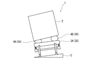
- FIG. 1 is a schematic front view of a railway vehicle 1 according to the first embodiment.
- FIG. 2 is a plan view of the wheel load adjusting device 10 of the railway vehicle 1 shown in FIG.
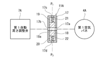
- FIG. 3 is a schematic cross-sectional view of the wheel load adjusting valve 4A shown in FIG.
- a cant C height difference
- the railway vehicle 1 includes a vehicle body 2, first and second carriages 3A, 3B, first to fourth air springs 4A, 4B, 5A, 5B, an air reservoir 6, First to fourth automatic height adjusting valves 7A, 7B, 8A, 8B and a wheel load adjusting device 10 are provided.
- the vehicle body 2 has a substantially rectangular parallelepiped shape extending in the rail direction.
- the first carriage 3A is disposed on one side of the vehicle longitudinal direction and supports one end of the vehicle body 2 in the longitudinal direction of the vehicle body.
- the second carriage 3B is disposed on the other side of the vehicle longitudinal direction and extends in the longitudinal direction of the vehicle body 2. Support the other end.
- the first air spring 4A and the second air spring 4B are disposed apart from each other in the vehicle width direction between the vehicle body 2 and the first carriage 3A, and the first air spring 4A is disposed on one side in the vehicle width direction,
- the second air spring 4B is disposed on the other side in the vehicle width direction.
- the third air spring 5A and the fourth air spring 5B are arranged apart from each other in the vehicle width direction between the vehicle body 2 and the second carriage 3B, and the third air spring 5A is arranged on one side in the vehicle width direction,
- the fourth air spring 5B is disposed on the other side in the vehicle width direction.
- the air reservoir 6 is configured such that compressed air is accumulated and the compressed air is replenished from a compressor (not shown) mounted on the railway vehicle 1 when the pressure in the air reservoir 6 drops below a predetermined value. Yes.
- the first to fourth automatic height adjustment valves 7A, 7B, 8A, 8B are known devices that are also called leveling valves.
- the first to fourth automatic height adjustment valves 7A, 7B, 8A, 8B are arranged on the upstream side (air reservoir 6 side) of the first to fourth air springs 4A, 4B, 5A, 5B, respectively.
- the height of each of the fourth air springs 4A, 4B, 5A, 5B is adjusted to keep the height of each air spring constant.
- the first automatic height adjustment valve 7A supplies and exhausts the first air spring 4A mechanically in conjunction with the vertical displacement between the vehicle width direction portion of the carriage frame of the first carriage 3A and the vehicle body 2. To do.
- the second automatic height adjustment valve 7B supplies and exhausts the second air spring 4B mechanically interlocking with the vertical displacement between the other side in the vehicle width direction of the carriage frame of the first carriage 3A and the vehicle body 2.
- the third automatic height adjusting valve 8A supplies and exhausts the third air spring 5A mechanically in conjunction with the vertical displacement between the vehicle width direction one side portion of the carriage frame of the second carriage 3B and the vehicle body 2.
- the fourth automatic height adjustment valve 8B supplies and exhausts the fourth air spring 5B mechanically interlocking with the vertical displacement between the vehicle body 2 and the other side in the vehicle width direction of the carriage frame of the second carriage 3B. To do.
- the first to fourth automatic height adjustment valves 7A, 7B, 8A, 8B respectively correspond to the corresponding air springs 4A, 4B when the corresponding air springs 4A, 4B, 5A, 5B become higher than a predetermined height.
- 5A, 5B are exhausted to the atmosphere, and when the height becomes lower than a predetermined value, air is supplied from the air reservoir 6 to the corresponding air springs 4A, 4B, 5A, 5B.
- the wheel load adjustment device 10 includes first to fourth automatic height adjustment valves so as to suppress an increase in pressure difference between at least two of the first to fourth air springs 4A, 4B, 5A, and 5B.
- the supply / exhaust operation of at least one automatic height adjustment valve among 7A, 7B, 8A, and 8B is limited.
- the wheel load adjusting device 10 includes a first wheel load adjusting valve 11A provided in a first flow path 13A connecting the first automatic height adjusting valve 7A and the first air spring 4A, and a second automatic height adjusting.
- the second wheel load adjustment valve 11B provided in the second flow path 13B that connects the valve 7B and the second air spring 4B, and the third flow path 14A that connects the third automatic height adjustment valve 8A and the third air spring 5A.
- a fourth wheel weight adjusting valve 12B provided in a fourth flow path 14B connecting the fourth automatic height adjusting valve 8B and the fourth air spring 5B.
- the wheel load adjusting device 10 further includes a first pilot pipe 15A that transmits the pressure of the first air spring 4A as a pilot pressure to the first wheel load adjusting valve 11A and the third wheel load adjusting valve 12A, and a second air spring 4B.
- the pilot pressure is used as the pilot pressure to transmit the second pilot pipe 15B to the second wheel weight adjustment valve 11B and the fourth wheel weight adjustment valve 12B
- the pressure of the third air spring 5A is used as the pilot pressure.
- a third pilot pipe 16A that transmits to the third wheel weight adjustment valve 12A
- a fourth pilot pipe that transmits the pressure of the fourth air spring 5B to the second wheel weight adjustment valve 11B and the fourth wheel weight adjustment valve 12B as the pilot pressure. 16B.
- the first differential pressure ⁇ P A between the first air spring 4A and the third air spring 5A arranged on one side in the vehicle width direction is a threshold TH. the if it exceeds, by suppressing the increase in the first differential pressure [Delta] P a to squeeze or block the first flow path 13A and the third channel 14A, respectively, the first automatic height adjustment valve 7A, and third automatic The flow rate (supply / exhaust operation) of the height adjustment valve 8A is limited.
- the second differential pressure ⁇ P B between the second air spring 4B and the fourth air spring 5B disposed on the other side in the vehicle width direction is the threshold value TH. Is exceeded, the second flow path 13B and the fourth flow path 14B are throttled or cut off to suppress the increase in the second differential pressure ⁇ P B , respectively.
- the flow rate (supply / exhaust operation) of the height adjustment valve 8B is limited.
- the first wheel load adjustment valve 11 ⁇ / b> A is a differential pressure valve including a casing 17 and a spool 18 housed in the casing 17 so as to be reciprocally displaceable.
- the casing 17 is formed with connection ports 17a and 17b communicating with the first air spring 4A and the first automatic height adjustment valve 7A, respectively.
- the spool 18 is formed with a passage 18a communicating with the connection ports 17a and 17b in the neutral position.
- a first pressure chamber 19 is formed between one end surface of the spool 18 in the displacement direction and the casing 17, and a second pressure chamber 20 is formed between the other end surface of the spool 18 in the displacement direction and the casing 17. Yes.
- a first coil spring 21 and a second coil spring 22 are accommodated in the first pressure chamber 19 and the second pressure chamber 20, respectively.
- a first pilot port 17 c that introduces the pressure P 1 of the first air spring 4 A into the first pressure chamber 19
- a second that introduces the pressure P 3 of the third air spring 5 A into the second pressure chamber 20.
- a pilot port 17d is formed. Spool 18 when the pressure P 1 of the first air spring 4A and the pressure P 3 of the third air springs 5A are the same, is held in a neutral position by the urging force of the first coil spring 21 and the second coil spring 22.
- the second to fourth wheel weight adjusting valves 11B, 12A, 12B have the same structure as the first wheel weight adjusting valve 11A, and thus detailed description thereof is omitted.
- the first air spring 4A disposed on one side in the vehicle width direction and one side in the vehicle longitudinal direction when passing through the curve of the railway vehicle 1, the one side in the vehicle width direction and the other side in the vehicle longitudinal direction.
- the first differential pressure ⁇ P A between the third air spring 5A and the third air spring 5A exceeds the threshold value TH
- the first wheel load adjustment valve 11A and the third wheel load adjustment valve 12A have the first difference. because squeezing the first flow path 13A and the third channel 14A or blocked so as to suppress an increase in pressure [Delta] P a, prevented from load balance is disturbed between the first air spring 4A and the third air spring 5A Thus, wheel load fluctuation can be suppressed.
- the second wheel weight adjusting valve 11B and the fourth wheel weight adjusting valve 12B also prevent the load balance between the second air spring 4B and the fourth air spring 5B from being lost. Heavy fluctuations can be suppressed.
- the railcar 1 travels to the right in FIG. 2 and passes a curve that turns diagonally downward to the right, when passing through the entrance relaxation curve at a low speed
- the third air spring 5A on the outer track side in the two-wheeled vehicle 3B is extended in the vertical direction by the twist of the vehicle body 2 to reduce the pressure, and the third automatic height adjustment valve 8A attempts to exhaust the third air spring 5A.
- the flow of the exhaust is throttled or blocked by the third wheel load adjustment valve 12A, further pressure drop of the third air spring 5A is suppressed, and the promotion of wheel load loss can be prevented.
- the vehicle body 2 of the railway vehicle 1 is long in the traveling direction, pitching is less likely to occur than rolling. Therefore, the difference between the first air spring 4A (second air spring 4B) disposed on one side in the vehicle longitudinal direction and the third air spring 5A (fourth air spring 5B) disposed on the other side in the vehicle longitudinal direction.
- the threshold value TH can be determined without much consideration of events other than the curve passing, and the wheel load adjusting during the curve passing can be accurately performed. it can.
- the first to fourth wheel load adjusting valves 11A, 11B, 12A, 12B operate mechanically according to the differential pressure ⁇ P A ( ⁇ P B ), a sensor and a controller can be dispensed with.
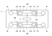
- FIG. 4 is a plan view of a modified wheel load adjusting device.
- the first to fourth wheel weight adjustment valves 11A, 11B, 12A, and 12B are respectively provided with the same casing 51A as the first to fourth automatic height adjustment valves 7A, 7B, 8A, and 8B. It may be accommodated in 51B, 52A, 52B and individually unitized. Then, the connection work between each of the first to fourth wheel weight adjustment valves 11A, 11B, 12A, 12B and each of the first to fourth automatic height adjustment valves 7A, 7B, 8A, 8B is performed on the vehicle. This eliminates the need for an assembly site and improves assembly workability.
- the unitization in which the wheel load adjusting valve and the automatic height adjusting valve are accommodated in the same housing can be applied to other embodiments described later.
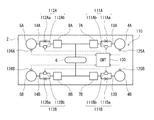
- FIG. 5 is a plan view of the wheel load adjusting device 110 for a railway vehicle according to the second embodiment.
- symbol is attached
- the wheel load adjusting device 110 includes first to fourth wheel load adjusting valves 111A, 111B, 112A, 112B, first to fourth pressure sensors 125A, 125B, 126A, 126B, and a controller 130.
- the first wheel load adjustment valve 111A includes a first fixed throttle 111Aa provided in one flow path in a region formed in parallel in the first flow path 13A and a first electromagnetic cutoff provided in the other flow path in the region. And a valve 111Ab.
- the second wheel load regulating valve 111B includes a second fixed throttle 111Ba provided in one flow path of the region formed in parallel in the second flow channel 13B and a second electromagnetic cutoff provided in the other flow channel of the region. And a valve 111Bb.
- the third wheel load adjusting valve 112A includes a third fixed throttle 112Aa provided in one flow path in a region formed in parallel among the third flow paths 14A, and a third electromagnetic cutoff provided in the other flow path in the region. And a valve 112Ab.
- the fourth wheel load adjusting valve 112B includes a fourth fixed throttle 112Ba provided in one flow path of the region formed in parallel among the fourth flow channels 14B, and a fourth electromagnetic cutoff provided in the other flow channel of the region. And a valve 112Bb.
- the first to fourth electromagnetic cutoff valves 111Ab, 111Bb, 112Ab, and 112Bb are normally open types, and open the flow path in a non-powered state.
- the first to fourth pressure sensors 125A, 125B, 126A, and 126B detect the pressures of the first to fourth air springs 4A, 4B, 5A, and 5B, respectively.
- the controller 130 controls the first to fourth electromagnetic cutoffs of the first to fourth wheel load regulating valves 111A, 111B, 112A, 112B according to the pressure detected by the first to fourth pressure sensors 125A, 125B, 126A, 126B.
- the valves 111Ab, 111Bb, 112Ab, and 112Bb are controlled.
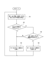
- FIG. 6 is a flowchart for explaining the operation of the wheel load adjusting device 110 shown in FIG.
- the controller 130 determines whether or not the pressure detected by at least one of the first pressure sensor 125A and the third pressure sensor 126A satisfies a predetermined high pressure condition.
- the controller 130 calculates an average value of the pressure detected by the first pressure sensor 125A and the pressure detected by the third pressure sensor 126A (step S1), and the calculated pressure average value is a predetermined pressure. It is determined whether it is above (for example, more than the pressure at the time of a stop) (step S2).
- the controller 130 may be configured to determine whether or not the pressure detected by either the first pressure sensor 125A or the third pressure sensor 126A is equal to or higher than a predetermined pressure. It is good also as a structure which determines whether both each pressure detected by 1A pressure sensor 125A and 3rd pressure sensor 126A is more than predetermined pressure.
- step S2 If it is determined that the pressure average value is equal to or higher than the predetermined pressure (step S2), it is considered that none of the wheel loads will be extremely reduced even if the wheel load fluctuation occurs.
- the first electromagnetic cutoff valve 111Ab and the third electromagnetic cutoff valve 112Ab are opened (step S3). That is, when each pressure of the first air spring 4A and the third air spring 5A satisfies a predetermined high pressure condition, the first differential pressure ⁇ P A by the first wheel weight adjustment valve 111A and the third wheel weight adjustment valve 112A is reduced. Since the operation to suppress the increase is prohibited, power consumption can be suppressed.
- the controller 130 detects the pressure P 1 detected by the first pressure sensor 125A and the pressure detected by the third pressure sensor 126A.
- the first differential pressure [Delta] P a determines whether or not exceeding the threshold value TH between the P 3 (step S4).
- step S4 If the first differential pressure [Delta] P A is determined not to exceed the threshold value TH (step S4), and the controller 130 in the open state of the first solenoid shut-off valve 111Ab and third solenoid shutoff valve 112Ab (step S3). On the other hand, if the first differential pressure [Delta] P A is determined to have exceeded the threshold value TH (step S4), and the controller 130 in the closed state of the first solenoid shut-off valve 111Ab and third solenoid shutoff valve 112Ab (step S5). Thus, an increase of the first differential pressure [Delta] P A during curving is suppressed, thereby suppressing the wheel load variation.
- the operation of the second and fourth wheel weight adjustment valves 111B and 112B is the same as the operation of the first and third wheel weight adjustment valves 111A and 112A, and detailed description thereof is omitted.
- the controller 130 closes the first electromagnetic cutoff valve 111Ab and the third electromagnetic cutoff valve 112Ab.
- the threshold TH may be increased so that the first differential pressure ⁇ P A does not easily exceed the threshold.
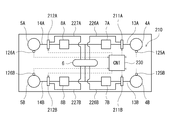
- FIG. 7 is a plan view of the wheel load adjusting device 210 for a railway vehicle according to the third embodiment.
- the wheel load adjusting device 210 includes a first wheel load adjusting valve 211A provided in the first flow path 13A, a second wheel load adjusting valve 211B provided in the second flow path 13B, and a third A third wheel weight adjusting valve 212A provided in the flow path 14A and a fourth wheel weight adjusting valve 212B provided in the fourth flow path 14B are provided.
- the first to fourth wheel load adjustment valves 211A, 211B, 212A, 212B are electromagnetic switching valves.
- the wheel weight adjusting device 210 further includes a first bypass pipe 226A that bypasses the first automatic height adjusting valve 7A and connects the first wheel weight adjusting valve 211A to the air reservoir 6, and a second automatic height adjusting valve 7B.
- 2nd bypass pipe 226B that connects the second wheel weight adjustment valve 211B to the air reservoir 6 and bypasses the third automatic height adjustment valve 8A and connects the third wheel weight adjustment valve 212A to the air reservoir 6
- a third bypass pipe 227A that bypasses the fourth automatic height adjustment valve 8B and a fourth bypass pipe 227B that connects the fourth wheel weight adjustment valve 212B to the air reservoir 6.
- the wheel load adjusting device 210 further includes first to fourth pressure sensors 125A, 125B, 126A, 126B, and a controller 230.
- the controller 230 controls the first to fourth wheel load adjustment valves 211A, 211B, 212A, and 212B according to the pressures detected by the first to fourth pressure sensors 125A, 125B, 126A, and 126B.
- FIG. 8 is a schematic diagram of the first wheel load adjustment valve 211A shown in FIG.
- the first wheel load adjustment valve 211A causes the first air spring 4A to communicate with the first automatic height adjustment valve 7A in the neutral position and the first air spring 4A to hold the air in the first switching position. 6 and the first air spring 4A is communicated with the exhaust port opened to the atmosphere at the second switching position.
- the first wheel load adjustment valve 211A is urged by a spring so as to be held at the neutral position in the non-power supply state.
- the second to fourth wheel load adjustment valves 211B, 212A, and 212B have the same structure as the first wheel load adjustment valve 211A, and detailed description thereof is omitted.
- FIG. 9 is a flowchart for explaining the operation of the wheel load adjusting device 210 shown in FIG.
- steps S1, S2, and S4 are the same as those in the second embodiment, and thus detailed description thereof is omitted.
- the controller 230 determines Yes in step S2, it is considered that none of the wheel loads will become extremely small even if the wheel load fluctuations occur. Therefore, the first wheel load adjusting valve 211A and the third wheel load adjusting valve The wheel load adjustment valve 212A is set to the neutral position (step S13).
- the controller 230 controls the first wheel weight adjustment valve 211A and the third wheel weight adjustment valve 212A, respectively, and the first air spring.
- the compressed air from the air reservoir 6 is supplied to the low pressure side air spring of the 4A and the third air spring 5A (first switching position), and the high pressure side of the first air spring 4A and the third air spring 5A is supplied.
- the air spring is exhausted (second switching position).
- the controller 230 performs the second wheel load adjustment valve 211B and The fourth wheel load adjustment valve 212B is controlled, and the compressed air from the air reservoir 6 is supplied to the low-pressure side air spring of the second air spring 4B and the fourth air spring 5B, and the second air spring 4B and The fourth air spring 5B is exhausted to the high-pressure side air spring.
- the controller 230 controls the first wheel weight adjustment valve 211A and the third wheel weight adjustment valve 212A.
- the value of the threshold value TH may be increased so that the first differential pressure ⁇ P A does not easily exceed the threshold value.
- FIG. 10 is a plan view for explaining definitions of names and directions of respective parts of the railway vehicle in the simulation.
- FIG. 11A is a graph showing the relationship between cant and time in the simulation.
- FIG. 11B is a graph showing the relationship between the air spring pressure and time of the simulation result.
- FIG.11 (c) is a graph which shows the relationship between the wheel load of simulation result, and time.
- the railway vehicle equipped with the wheel load adjusting device of the first embodiment was used as an example, and the rail vehicle not equipped with the wheel load adjusting device was used as a comparative example.
- the conditions of this simulation were as shown in Table 1 below.
- the thick line indicates the simulation result of the example
- the thin line indicates the simulation result of the comparative example.
- FIGS. 11 (a) to 11 (c) according to the simulation results, in the comparative example, when the front carriage passes the main curve and the rear carriage passes the entrance relaxation curve, The pressure of the third air spring on the side and on the outer gauge side decreased, and the wheel load on the outer gauge side wheel (left of the fourth axis) of the rear carriage decreased.
- the pressure drop of the third air spring is suppressed (A position in FIG. 11 (b)), and the wheel weight of the wheel on the outer gauge side of the rear carriage (the fourth axis left) is reduced. It was suppressed (B location in FIG. 11 (c)). In other words, it was confirmed that the example was effective in preventing wheel load loss when passing a curve.
Landscapes
- Engineering & Computer Science (AREA)
- Mechanical Engineering (AREA)
- Vehicle Body Suspensions (AREA)
Abstract
車体と第1台車との間に、車幅方向に離間して配置される第1空気バネ及び第2空気バネと、前記車体と第2台車との間に、車幅方向に離間して配置される第3空気バネ及び第4空気バネと、前記第1~第4空気バネの上流側に配置されて前記第1~第4空気バネの高さをそれぞれ調整し、空気バネ高さを一定に保つ第1~第4自動高さ調整弁と、を備えた鉄道車両に用いる輪重調整装置であって、前記鉄道車両の曲線通過時において、前記第1~第4空気バネのうち少なくとも2つの空気バネ間の圧力差の増加を抑制するように、前記第1~第4自動高さ調整弁のうち少なくとも1つの自動高さ調整弁の給排気動作を制限する。
Description
本発明は、鉄道車両の輪重調整装置に関する。
鉄道車両には、車体と台車との間に介設された空気バネの給排気を行う自動高さ調整弁が搭載されている。自動高さ調整弁は、空気バネが鉛直方向に伸びた場合には排気を行い、空気バネが鉛直方向に縮んだ場合には圧縮空気を給気する。
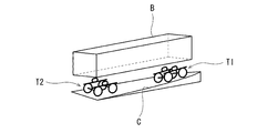
ところで、図12に示すように、鉄道車両がカントのある軌道曲線を通過する際、緩和曲線(軌道曲線の出入口部分)の走行時には、前台車T1の位置と後台車T2の位置とでカントCの大きさが異なる。そのため、既存の剛な車体Bを通常の空気バネを介して台車T1,T2で支持した鉄道車両が緩和曲線を走行した場合、車体Bに捩れ力が作用して各空気バネ間の荷重バランスが崩れ、輪重変動が生じる。しかも、車体の捩れにより鉛直方向に伸ばされた空気バネは、自動高さ調整弁により排気されて更に圧力が低下するため、輪重抜けが助長されることにもなる。
特許文献1の装置では、進行方向前側の台車及び車体の車幅方向の傾斜角度に応じて、進行方向後側の空気バネの高さを調整することで、車両の曲線走行時に車体に作用する捩れ力を緩和している。
しかし、特許文献1の装置は、空気バネの高さを調整するものであって、空気バネの圧力を調整するものではないため、車体の捩れが緩和されたとしても、空気バネの圧力差によって輪重変動が生じる。
そこで本発明は、鉄道車両の曲線走行時における輪重変動を低減することを目的とする。
本発明の一態様に係る鉄道車両の輪重調整装置は、車体と第1台車との間に、車幅方向に離間して配置される第1空気バネ及び第2空気バネと、前記車体と第2台車との間に、車幅方向に離間して配置される第3空気バネ及び第4空気バネと、前記第1~第4空気バネの上流側に配置されて前記第1~第4空気バネの高さをそれぞれ調整し、空気バネ高さを一定に保つ第1~第4自動高さ調整弁と、を備えた鉄道車両に用いる輪重調整装置であって、前記鉄道車両の曲線通過時において、前記第1~第4空気バネのうち少なくとも2つの空気バネ間の圧力差の増加を抑制するように、前記第1~第4自動高さ調整弁のうち少なくとも1つの自動高さ調整弁の給排気動作を制限する。
前記構成によれば、鉄道車両の曲線走行時に、第1~第4空気バネのうち少なくとも2つの空気バネ間の圧力差の増加を抑制するように、第1~第4自動高さ調整弁のうち少なくとも1つの自動高さ調整弁の給排気動作を制限するので、空気バネ間の荷重バランスが崩れることが抑制され、輪重変動を抑制できる。
本発明によれば、鉄道車両の曲線走行時における輪重変動を低減できる。
以下、図面を参照して実施形態を説明する。なお、以下の説明では、鉄道車両の車体が延びる方向(即ち、レール方向)を車両長手方向とし、それに直交する幅方向(即ち、枕木方向)を車幅方向として定義する。また、車両が走行する進行方向の先頭側を前側とし、その反対側を後側と定義する。
(第1実施形態)
図1は、第1実施形態に係る鉄道車両1の概略正面図である。図2は、図1に示す鉄道車両1の輪重調整装置10の平面図である。図3は、図2に示す輪重調整弁4Aの模式断面図である。図1に示すように、鉄道車両1が走行する軌道の曲線区間においては、曲線外側のレールが曲線内側のレールよりも高くなるように、レール載置面にカントC(高低差)が設けられている。図1及び2に示すように、鉄道車両1は、車体2と、第1及び第2台車3A,3Bと、第1~第4空気バネ4A,4B,5A,5Bと、空気溜め6と、第1~第4自動高さ調整弁7A,7B,8A,8Bと、輪重調整装置10とを備える。車体2は、レール方向に延びた略直方体形状を有する。第1台車3Aは、車両長手方向一方側に配置されて車体2の車両長手方向の一端部を支持し、第2台車3Bは、車両長手方向他方側に配置されて車体2の車両長手方向の他端部を支持する。
図1は、第1実施形態に係る鉄道車両1の概略正面図である。図2は、図1に示す鉄道車両1の輪重調整装置10の平面図である。図3は、図2に示す輪重調整弁4Aの模式断面図である。図1に示すように、鉄道車両1が走行する軌道の曲線区間においては、曲線外側のレールが曲線内側のレールよりも高くなるように、レール載置面にカントC(高低差)が設けられている。図1及び2に示すように、鉄道車両1は、車体2と、第1及び第2台車3A,3Bと、第1~第4空気バネ4A,4B,5A,5Bと、空気溜め6と、第1~第4自動高さ調整弁7A,7B,8A,8Bと、輪重調整装置10とを備える。車体2は、レール方向に延びた略直方体形状を有する。第1台車3Aは、車両長手方向一方側に配置されて車体2の車両長手方向の一端部を支持し、第2台車3Bは、車両長手方向他方側に配置されて車体2の車両長手方向の他端部を支持する。
第1空気バネ4A及び第2空気バネ4Bは、車体2と第1台車3Aとの間において互いに車幅方向に離間して配置され、第1空気バネ4Aは車幅方向一方側に配置され、第2空気バネ4Bは車幅方向他方側に配置されている。第3空気バネ5A及び第4空気バネ5Bは、車体2と第2台車3Bとの間において互いに車幅方向に離間して配置され、第3空気バネ5Aは車幅方向一方側に配置され、第4空気バネ5Bは車幅方向他方側に配置されている。空気溜め6は、圧縮空気が溜められ、空気溜め6内の圧力が所定値未満に低下すると、鉄道車両1に搭載されたコンプレッサー(図示せず)から圧縮空気が補充されるように構成されている。
第1~第4自動高さ調整弁7A,7B,8A,8Bは、レベリングバルブとも呼ばれる公知の装置である。第1~第4自動高さ調整弁7A,7B,8A,8Bは、第1~第4空気バネ4A,4B,5A,5Bの上流側(空気溜め6側)にそれぞれ配置され、第1~第4空気バネ4A,4B,5A,5Bの高さをそれぞれ調整し、各空気バネ高さを一定に保つ。第1自動高さ調整弁7Aは、第1台車3Aの台車枠の車幅方向一方側の部分と車体2との間の鉛直方向変位に機械的に連動して第1空気バネ4Aを給排気する。第2自動高さ調整弁7Bは、第1台車3Aの台車枠の車幅方向他方側の部分と車体2との間の鉛直方向変位に機械的に連動して第2空気バネ4Bを給排気する。第3自動高さ調整弁8Aは、第2台車3Bの台車枠の車幅方向一方側の部分と車体2との間の鉛直方向変位に機械的に連動して第3空気バネ5Aを給排気する。第4自動高さ調整弁8Bは、第2台車3Bの台車枠の車幅方向他方側の部分と車体2との間の鉛直方向変位に機械的に連動して第4空気バネ5Bを給排気する。即ち、第1~第4自動高さ調整弁7A,7B,8A,8Bは、それぞれ対応する空気バネ4A,4B,5A,5Bの高さが所定以上に高くなると、対応する空気バネ4A,4B,5A,5Bから大気への排気を行い、当該高さが所定以上に低くなると、対応する空気バネ4A,4B,5A,5Bへ空気溜め6から給気を行う。
輪重調整装置10は、第1~第4空気バネ4A,4B,5A,5Bのうち少なくとも2つの空気バネ間の圧力差の増加を抑制するように、第1~第4自動高さ調整弁7A,7B,8A,8Bのうち少なくとも1つの自動高さ調整弁の給排気動作を制限する。一例として、輪重調整装置10は、第1自動高さ調整弁7Aと第1空気バネ4Aとを繋ぐ第1流路13Aに設けた第1輪重調整弁11Aと、第2自動高さ調整弁7Bと第2空気バネ4Bとを繋ぐ第2流路13Bに設けた第2輪重調整弁11Bと、第3自動高さ調整弁8Aと第3空気バネ5Aとを繋ぐ第3流路14Aに設けた第3輪重調整弁12Aと、第4自動高さ調整弁8Bと第4空気バネ5Bとを繋ぐ第4流路14Bに設けた第4輪重調整弁12Bとを備える。
輪重調整装置10は、更に、第1空気バネ4Aの圧力をパイロット圧として第1輪重調整弁11A及び第3輪重調整弁12Aに伝達する第1パイロット管15Aと、第2空気バネ4Bの圧力をパイロット圧として第2輪重調整弁11B及び第4輪重調整弁12Bに伝達する第2パイロット管15Bと、第3空気バネ5Aの圧力をパイロット圧として第1輪重調整弁11A及び第3輪重調整弁12Aに伝達する第3パイロット管16Aと、第4空気バネ5Bの圧力をパイロット圧として第2輪重調整弁11B及び第4輪重調整弁12Bに伝達する第4パイロット管16Bとを備える。
第1輪重調整弁11A及び第3輪重調整弁12Aは、車幅方向一方側に配置された第1空気バネ4Aと第3空気バネ5Aとの間の第1差圧ΔPAが閾値THを超えた場合に、それぞれ第1流路13A及び第3流路14Aを絞る又は遮断して第1差圧ΔPAの増加を抑制することで、第1自動高さ調整弁7A及び第3自動高さ調整弁8Aの流量(給排気動作)を制限する。第2輪重調整弁11B及び第4輪重調整弁12Bは、車幅方向他方側に配置された第2空気バネ4Bと第4空気バネ5Bとの間の第2差圧ΔPBが閾値THを超えた場合に、それぞれ第2流路13B及び第4流路14Bを絞る又は遮断して第2差圧ΔPBの増加を抑制することで、第2自動高さ調整弁7B及び第4自動高さ調整弁8Bの流量(給排気動作)を制限する。
一例として、図3に示すように、第1輪重調整弁11Aは、ケーシング17と、ケーシング17内に往復変位可能に収納されたスプール18とを備える差圧弁である。ケーシング17には、第1空気バネ4A及び第1自動高さ調整弁7Aにそれぞれ連通する接続ポート17a,17bが形成されている。スプール18には、中立位置において接続ポート17a,17bと連通する通路18aが形成されている。スプール18の変位方向の一端面とケーシング17との間には第1圧力室19が形成され、スプール18の変位方向の他端面とケーシング17との間には第2圧力室20が形成されている。
第1圧力室19及び第2圧力室20には、それぞれ第1コイルバネ21及び第2コイルバネ22が収容されている。ケーシング17には、第1空気バネ4Aの圧力P1を第1圧力室19に導入する第1パイロットポート17cと、第3空気バネ5Aの圧力P3を第2圧力室20に導入する第2パイロットポート17dとが形成されている。スプール18は、第1空気バネ4Aの圧力P1と第3空気バネ5Aの圧力P3とが同じであるとき、第1コイルバネ21及び第2コイルバネ22の付勢力により中立位置に保持される。スプール18は、第1差圧ΔPAが閾値THを超えた場合に、第1流路13Aを絞るように変位し、その絞り開度(絞られた流路の開度)は第1差圧ΔPAが増加するにつれて減少する。なお、第2~第4輪重調整弁11B,12A,12Bについては、第1輪重調整弁11Aと同様の構造であるため詳細な説明を省略する。
以上に説明した構成によれば、鉄道車両1の曲線通過時に、車幅方向一方側かつ車両長手方向一方側に配置された第1空気バネ4Aと、車幅方向一方側かつ車両長手方向他方側に配置された第3空気バネ5Aとの間の第1差圧ΔPAが増加して閾値THを超えた場合に、第1輪重調整弁11A及び第3輪重調整弁12Aが第1差圧ΔPAの増加を抑制するように第1流路13A及び第3流路14Aを絞る又は遮断するので、第1空気バネ4Aと第3空気バネ5Aとの間の荷重バランスが崩れることが抑制され、輪重変動を抑制できる。また、第2輪重調整弁11B及び第4輪重調整弁12Bも、これと同様にして、第2空気バネ4Bと第4空気バネ5Bとの間の荷重バランスが崩れることを抑制し、輪重変動を抑制できる。
また、例えば、鉄道車両1が図2中の右方に走行して右斜め下に旋回する曲線を通過すると仮定した場合、低速で入口緩和曲線を通過する際には、進行方向後側の第2台車3Bにおける外軌側の第3空気バネ5Aが車体2の捩れにより鉛直方向に伸ばされて圧力が低下し、更に第3自動高さ調整弁8Aが第3空気バネ5Aを排気しようとするが、その排気の流れが第3輪重調整弁12Aにより絞られる又は遮断されるので、第3空気バネ5Aの更なる圧力の低下が抑制され、輪重抜けの助長を防止できる。
また、鉄道車両1の車体2は進行方向に長いため、ローリングよりもピッチングの方が発生し難い。よって、車両長手方向一方側に配置された第1空気バネ4A(第2空気バネ4B)と車両長手方向他方側に配置された第3空気バネ5A(第4空気バネ5B)との間の差圧ΔPA(ΔPB)に基づいて輪重調整を行うことで、曲線通過以外の事象をあまり考慮せずに閾値THを決めることができ、曲線通過時の輪重調整を精度良く行うことができる。また、第1~第4輪重調整弁11A,11B,12A,12Bは差圧ΔPA(ΔPB)に応じて機械的に動作するので、センサ及びコントローラを不要とすることができる。
また、図4は、変形例の輪重調整装置の平面図である。図4に示すように、第1~第4輪重調整弁11A,11B,12A,12Bは、それぞれ第1~第4自動高さ調整弁7A,7B,8A,8Bと共通の筐体51A,51B,52A,52Bに収容されて個々にユニット化されてもよい。そうすれば、第1~第4輪重調整弁11A,11B,12A,12Bの各々と第1~第4自動高さ調整弁7A,7B,8A,8Bの各々との間の接続作業を車両組立現場で行わずに済み、組立作業性が向上する。なお、輪重調整弁と自動高さ調整弁とを同じ筐体に収容するユニット化は、後述する他の実施形態にも適用可能である。
(第2実施形態)
図5は、第2実施形態に係る鉄道車両の輪重調整装置110の平面図である。なお、第1実施形態と共通する構成については同一符号を付して説明を省略する。図5に示すように、輪重調整装置110は、第1~第4輪重調整弁111A,111B,112A,112Bと、第1~第4圧力センサ125A,125B,126A,126Bと、コントローラ130とを備える。
図5は、第2実施形態に係る鉄道車両の輪重調整装置110の平面図である。なお、第1実施形態と共通する構成については同一符号を付して説明を省略する。図5に示すように、輪重調整装置110は、第1~第4輪重調整弁111A,111B,112A,112Bと、第1~第4圧力センサ125A,125B,126A,126Bと、コントローラ130とを備える。
第1輪重調整弁111Aは、第1流路13Aのうち並列に形成した領域の一方の流路に設けた第1固定絞り111Aaと、当該領域の他方の流路に設けた第1電磁遮断弁111Abとを有する。第2輪重調整弁111Bは、第2流路13Bのうち並列に形成した領域の一方の流路に設けた第2固定絞り111Baと、当該領域の他方の流路に設けた第2電磁遮断弁111Bbとを有する。第3輪重調整弁112Aは、第3流路14Aのうち並列に形成した領域の一方の流路に設けた第3固定絞り112Aaと、当該領域の他方の流路に設けた第3電磁遮断弁112Abとを有する。第4輪重調整弁112Bは、第4流路14Bのうち並列に形成した領域の一方の流路に設けた第4固定絞り112Baと、当該領域の他方の流路に設けた第4電磁遮断弁112Bbとを有する。なお、第1~第4電磁遮断弁111Ab,111Bb,112Ab,112Bbは、ノーマルオープン型であり、非給電状態で流路を開いている。
第1~第4圧力センサ125A,125B,126A,126Bは、それぞれ第1~第4空気バネ4A,4B,5A,5Bの圧力を検出する。コントローラ130は、第1~第4圧力センサ125A,125B,126A,126Bで検出される圧力に応じて第1~第4輪重調整弁111A,111B,112A,112Bの第1~第4電磁遮断弁111Ab,111Bb,112Ab,112Bbを制御する。
図6は、図5に示す輪重調整装置110の動作を説明するフローチャートである。図6に示すように、コントローラ130は、第1圧力センサ125A及び第3圧力センサ126Aの少なくとも一方で検出される圧力が所定の高圧条件を満たすか否かを判定する。一例として、コントローラ130は、第1圧力センサ125Aで検出される圧力と第3圧力センサ126Aで検出される圧力との平均値を算出し(ステップS1)、その算出された圧力平均値が所定圧以上(例えば、停車時の圧力以上)であるか否かを判定する(ステップS2)。なお、それに代えて、コントローラ130は、第1圧力センサ125A又は第3圧力センサ126Aのいずれ一方で検出される圧力が所定圧以上であるか否かを判定する構成としてもよいし、或いは、第1圧力センサ125A及び第3圧力センサ126Aで検出される各圧力の両方が所定圧以上であるか否かを判定する構成としてもよい。
圧力平均値が所定圧以上であると判定された場合には(ステップS2)、輪重変動が生じても各輪重のいずれもが極度に小さくなることはないと考えられるため、コントローラ130は、第1電磁遮断弁111Ab及び第3電磁遮断弁112Abを開いた状態にする(ステップS3)。即ち、第1空気バネ4A及び第3空気バネ5Aの各圧力が所定の高圧条件を満たす場合には、第1輪重調整弁111A及び第3輪重調整弁112Aによる第1差圧ΔPAの増加を抑制する動作が禁止されるので、電力消費を抑えることができる。他方、圧力平均値が所定圧以上ではないと判定された場合には(ステップS2)、コントローラ130は、第1圧力センサ125Aで検出された圧力P1と第3圧力センサ126Aで検出された圧力P3との間の第1差圧ΔPAが閾値THを超えたか否かを判定する(ステップS4)。
第1差圧ΔPAが閾値THを超えていないと判定された場合には(ステップS4)、コントローラ130は、第1電磁遮断弁111Ab及び第3電磁遮断弁112Abを開いた状態にする(ステップS3)。他方、第1差圧ΔPAが閾値THを超えたと判定された場合には(ステップS4)、コントローラ130は、第1電磁遮断弁111Ab及び第3電磁遮断弁112Abを閉じた状態にする(ステップS5)。これにより、曲線通過時における第1差圧ΔPAの増加が抑制され、輪重変動を抑制できる。なお、第2及び第4輪重調整弁111B,112Bの動作は、前記した第1及び第3輪重調整弁111A,112Aの動作と同様であるため詳細な説明を省略する。
なお、変形例として、第1空気バネ4A及び第3空気バネ5Aの圧力平均値が所定圧以上である場合において、コントローラ130は、第1電磁遮断弁111Ab及び第3電磁遮断弁112Abの閉動作を禁止する代わりに、閾値THの値を上げて第1差圧ΔPAが閾値を超え難くなるようにしてもよい。
(第3実施形態)
図7は、第3実施形態に係る鉄道車両の輪重調整装置210の平面図である。なお、第1又は第2実施形態と共通する構成については同一符号を付して説明を省略する。図7に示すように、輪重調整装置210は、第1流路13Aに設けた第1輪重調整弁211Aと、第2流路13Bに設けた第2輪重調整弁211Bと、第3流路14Aに設けた第3輪重調整弁212Aと、第4流路14Bに設けた第4輪重調整弁212Bとを備える。第1~第4輪重調整弁211A,211B,212A,212Bは、電磁切換弁である。
図7は、第3実施形態に係る鉄道車両の輪重調整装置210の平面図である。なお、第1又は第2実施形態と共通する構成については同一符号を付して説明を省略する。図7に示すように、輪重調整装置210は、第1流路13Aに設けた第1輪重調整弁211Aと、第2流路13Bに設けた第2輪重調整弁211Bと、第3流路14Aに設けた第3輪重調整弁212Aと、第4流路14Bに設けた第4輪重調整弁212Bとを備える。第1~第4輪重調整弁211A,211B,212A,212Bは、電磁切換弁である。
輪重調整装置210は、更に、第1自動高さ調整弁7Aを迂回して第1輪重調整弁211Aを空気溜め6に接続する第1バイパス管226Aと、第2自動高さ調整弁7Bを迂回して第2輪重調整弁211Bを空気溜め6に接続する第2バイパス管226Bと、第3自動高さ調整弁8Aを迂回して第3輪重調整弁212Aを空気溜め6に接続する第3バイパス管227Aと、第4自動高さ調整弁8Bを迂回して第4輪重調整弁212Bを空気溜め6に接続する第4バイパス管227Bとを備える。また、輪重調整装置210は、更に、第1~第4圧力センサ125A,125B,126A,126Bと、コントローラ230とを備える。コントローラ230は、第1~第4圧力センサ125A,125B,126A,126Bで検出される圧力に応じて第1~第4輪重調整弁211A,211B,212A,212Bを制御する。
図8は、図7に示す第1輪重調整弁211Aの模式図である。図8に示すように、第1輪重調整弁211Aは、中立位置において第1空気バネ4Aを第1自動高さ調整弁7Aに連通させ、第1切換位置において第1空気バネ4Aを空気溜め6に連通させ、第2切換位置において第1空気バネ4Aを大気開放された排気ポートに連通させる。第1輪重調整弁211Aは、非給電状態では中立位置に保持されるようにバネで付勢されている。なお、第2~第4輪重調整弁211B,212A,212Bは、第1輪重調整弁211Aと同構造であるため詳細な説明を省略する。
図9は、図7に示す輪重調整装置210の動作を説明するフローチャートである。図9に示すように、ステップS1,S2及びS4は、第2実施形態と同様であるため詳細な説明を省略する。コントローラ230は、ステップS2でYesと判定された場合、輪重変動が生じても各輪重のいずれもが極度に小さくなることはないと考えられるため、第1輪重調整弁211A及び第3輪重調整弁212Aを中立位置にしておく(ステップS13)。他方、ステップS2でNoと判定され、かつ、ステップS4でYesが判定された場合、コントローラ230は、第1輪重調整弁211A及び第3輪重調整弁212Aをそれぞれ制御し、第1空気バネ4A及び第3空気バネ5Aのうち低圧側の空気バネには空気溜め6からの圧縮空気を給気し(第1切換位置)、第1空気バネ4A及び第3空気バネ5Aのうち高圧側の空気バネには排気を行う(第2切換位置)。
また、コントローラ230は、上記同様にして、第2空気バネ4Bと第4空気バネ5Bとの間の第2差圧ΔPBが閾値THを超えた場合には、第2輪重調整弁211B及び第4輪重調整弁212Bをそれぞれ制御し、第2空気バネ4B及び第4空気バネ5Bのうち低圧側の空気バネには空気溜め6からの圧縮空気を給気し、第2空気バネ4B及び第4空気バネ5Bのうち高圧側の空気バネには排気を行う。このようすることで、曲線通過時における空気バネ間の差圧の増加が抑制され、輪重変動を抑制できる。
なお、変形例として、第1空気バネ4A及び第3空気バネ5Aの圧力平均値が所定圧以上である場合において、コントローラ230は、第1輪重調整弁211A及び第3輪重調整弁212Aの第1又は第2切換位置への切り換えを禁止して中立位置に保つ代わりに、閾値THの値を上げて第1差圧ΔPAが閾値を超え難くなるようにしてもよい。
(実施例/比較例)
図10は、シミュレーションにおける鉄道車両の各部の名称及び方向の定義を説明する平面図である。図11(a)は、シミュレーションにおけるカントと時間との関係を示すグラフである。図11(b)は、シミュレーション結果の空気バネ圧力と時間との関係を示すグラフである。図11(c)は、シミュレーション結果の輪重と時間との関係を示すグラフである。本シミュレーションでは、第1実施形態の輪重調整装置を搭載した鉄道車両を実施例とし、輪重調整装置を搭載しない鉄道車両を比較例とした。また、本シミュレーションの条件は、下記表1の通りとした。
図10は、シミュレーションにおける鉄道車両の各部の名称及び方向の定義を説明する平面図である。図11(a)は、シミュレーションにおけるカントと時間との関係を示すグラフである。図11(b)は、シミュレーション結果の空気バネ圧力と時間との関係を示すグラフである。図11(c)は、シミュレーション結果の輪重と時間との関係を示すグラフである。本シミュレーションでは、第1実施形態の輪重調整装置を搭載した鉄道車両を実施例とし、輪重調整装置を搭載しない鉄道車両を比較例とした。また、本シミュレーションの条件は、下記表1の通りとした。

図11(b)及び図11(c)では、太線が実施例のシミュレーション結果を示し、細線が比較例のシミュレーション結果を示す。図11(a)~(c)に示すように、シミュレーション結果によれば、比較例では、前台車が本曲線を通過し、かつ、後台車が入口緩和曲線を通過する時点において、進行方向後側かつ外軌側の第3空気バネの圧力が低下し、後台車の外軌側の車輪(第4軸左)の輪重が低下した。しかし、実施例では、同時点において、第3空気バネの圧力低下が抑制され(図11(b)のA箇所)、後台車の外軌側の車輪(第4軸左)の輪重低下が抑制された(図11(c)のB箇所)。即ち、実施例は、曲線通過時における輪重抜け防止に有効であることが確認された。
なお、本発明は前述した実施形態に限定されるものではなく、その構成を変更、追加、又は削除することができる。前記各実施形態は互いに任意に組み合わせてもよく、例えば1つの実施形態中の一部の構成又は方法を他の実施形態に適用してもよく、実施形態中の一部の構成は、その実施形態中の他の構成から分離して任意に抽出可能である。
1 鉄道車両
2 車体
3A 第1台車
3B 第2台車
4A 第1空気バネ
4B 第2空気バネ
5A 第3空気バネ
5B 第4空気バネ
6 空気溜め
7A 第1自動高さ調整弁
7B 第2自動高さ調整弁
8A 第3自動高さ調整弁
8B 第4自動高さ調整弁
10,110,210 輪重調整装置
11A,111A,211A 第1輪重調整弁
11B,111B,211B 第2輪重調整弁
12A,112A,212A 第3輪重調整弁
12B,112B,212B 第4輪重調整弁
13A 第1流路
13B 第2流路
14A 第3流路
14B 第4流路
51A,51B,52A,52B 筐体
125A 第1圧力センサ
125B 第2圧力センサ
126A 第3圧力センサ
126B 第4圧力センサ
130,230 コントローラ
2 車体
3A 第1台車
3B 第2台車
4A 第1空気バネ
4B 第2空気バネ
5A 第3空気バネ
5B 第4空気バネ
6 空気溜め
7A 第1自動高さ調整弁
7B 第2自動高さ調整弁
8A 第3自動高さ調整弁
8B 第4自動高さ調整弁
10,110,210 輪重調整装置
11A,111A,211A 第1輪重調整弁
11B,111B,211B 第2輪重調整弁
12A,112A,212A 第3輪重調整弁
12B,112B,212B 第4輪重調整弁
13A 第1流路
13B 第2流路
14A 第3流路
14B 第4流路
51A,51B,52A,52B 筐体
125A 第1圧力センサ
125B 第2圧力センサ
126A 第3圧力センサ
126B 第4圧力センサ
130,230 コントローラ
Claims (6)
- 車体と第1台車との間に、車幅方向に離間して配置される第1空気バネ及び第2空気バネと、前記車体と第2台車との間に、車幅方向に離間して配置される第3空気バネ及び第4空気バネと、前記第1~第4空気バネの上流側に配置されて前記第1~第4空気バネの高さをそれぞれ調整し、空気バネ高さを一定に保つ第1~第4自動高さ調整弁と、を備えた鉄道車両に用いる輪重調整装置であって、
前記鉄道車両の曲線通過時において、前記第1~第4空気バネのうち少なくとも2つの空気バネ間の圧力差の増加を抑制するように、前記第1~第4自動高さ調整弁のうち少なくとも1つの自動高さ調整弁の給排気動作を制限する、鉄道車両の輪重調整装置。 - 前記第1~第4自動高さ調整弁と前記第1~第4空気バネとを繋ぐ第1~第4流路にそれぞれ設けられた第1~第4輪重調整弁を備え、
前記第1輪重調整弁及び前記第3輪重調整弁は、車幅方向の一方側に配置された前記第1空気バネと前記第3空気バネとの間の第1差圧が第1閾値を超えた場合に、前記第1差圧の増加を抑制するように動作することで、前記第1自動高さ調整弁及び前記第3自動高さ調整弁による給排気動作を制限し、
前記第2輪重調整弁及び前記第4輪重調整弁は、車幅方向の他方側に配置された前記第2空気バネと前記第4空気バネとの間の第2差圧が第2閾値を超えた場合に、前記第2差圧の増加を抑制するように動作することで、前記第2自動高さ調整弁及び前記第4自動高さ調整弁による給排気動作を制限する、請求項1に記載の鉄道車両の輪重調整装置。 - 前記第1輪重調整弁及び前記第3輪重調整弁は、前記第1差圧が前記第1閾値を超えた場合に、前記第1流路及び前記第3流路を絞り又は遮断することで、前記第1自動高さ調整弁及び前記第3自動高さ調整弁における流量を制限し、
前記第2輪重調整弁及び前記第4輪重調整弁は、前記第2差圧が前記第2閾値を超えた場合に、前記第2流路及び前記第4流路を絞る又は遮断することで、前記第2自動高さ調整弁及び前記第4自動高さ調整弁における流量を制限する、請求項2に記載の鉄道車両の輪重調整装置。 - 前記第1輪重調整弁及び前記第3輪重調整弁は、前記第1差圧が前記第1閾値を超えた場合に、前記第1空気バネ及び前記第3空気バネのうち低圧側の空気バネに、空気溜めからの圧縮空気を給気するように動作し、
前記第2輪重調整弁及び前記第4輪重調整弁は、前記第2差圧が前記第2閾値を超えた場合に、前記第2空気バネ及び前記第4空気バネのうち低圧側の空気バネに、空気溜めからの圧縮空気を給気するように動作する、請求項2に記載の鉄道車両の輪重調整装置。 - 前記第1~第4空気バネの圧力をそれぞれ検出する第1~第4圧力センサと、
前記第1~第4圧力センサで検出される圧力に応じて前記第1~第4輪重調整弁を制御するコントローラと、を更に備え、
前記コントローラは、
前記第1空気バネ及び前記第3空気バネの少なくとも一方が所定の高圧条件を満たすとき、前記第1輪重調整弁及び前記第3輪重調整弁による前記第1差圧の増加を抑制する動作を禁止し、又は、前記第1閾値を上げ、
前記第2空気バネ及び前記第4空気バネの少なくとも一方が所定の高圧条件を満たすとき、前記第2輪重調整弁及び前記第4輪重調整弁による前記第2差圧の増加を抑制する動作を禁止し、又は、前記第2閾値を上げる、請求項1乃至4のいずれか1項に記載の鉄道車両の輪重調整装置。 - 前記第1~第4輪重調整弁は、それぞれ前記第1~第4自動高さ調整弁と共通の筐体に収容されてそれぞれユニット化されている、請求項1乃至5のいずれか1項に記載の鉄道車両の輪重調整装置。
Priority Applications (1)
| Application Number | Priority Date | Filing Date | Title |
|---|---|---|---|
| US16/097,428 US10981584B2 (en) | 2016-04-28 | 2017-04-27 | Wheel load adjusting apparatus of railcar |
Applications Claiming Priority (2)
| Application Number | Priority Date | Filing Date | Title |
|---|---|---|---|
| JP2016090612A JP6650337B2 (ja) | 2016-04-28 | 2016-04-28 | 鉄道車両の輪重調整装置 |
| JP2016-090612 | 2016-04-28 |
Publications (1)
| Publication Number | Publication Date |
|---|---|
| WO2017188367A1 true WO2017188367A1 (ja) | 2017-11-02 |
Family
ID=60159679
Family Applications (1)
| Application Number | Title | Priority Date | Filing Date |
|---|---|---|---|
| PCT/JP2017/016693 Ceased WO2017188367A1 (ja) | 2016-04-28 | 2017-04-27 | 鉄道車両の輪重調整装置 |
Country Status (3)
| Country | Link |
|---|---|
| US (1) | US10981584B2 (ja) |
| JP (1) | JP6650337B2 (ja) |
| WO (1) | WO2017188367A1 (ja) |
Families Citing this family (1)
| Publication number | Priority date | Publication date | Assignee | Title |
|---|---|---|---|---|
| JP6650337B2 (ja) * | 2016-04-28 | 2020-02-19 | 川崎重工業株式会社 | 鉄道車両の輪重調整装置 |
Citations (4)
| Publication number | Priority date | Publication date | Assignee | Title |
|---|---|---|---|---|
| JPH03295758A (ja) * | 1990-04-12 | 1991-12-26 | Sumitomo Metal Ind Ltd | 鉄道車両用空気ばねの応荷重型電子制御方法 |
| JP2003165436A (ja) * | 2001-11-30 | 2003-06-10 | Sumitomo Metal Ind Ltd | 鉄道車両用高さ調整弁装置及びその制御方法並びに鉄道車両 |
| US20110121526A1 (en) * | 2009-11-25 | 2011-05-26 | LTK Consulting Services, Inc. | Vertical position compensating device for a vehicle |
| JP2016002814A (ja) * | 2014-06-13 | 2016-01-12 | Kyb株式会社 | 鉄道車両の圧力調整装置及び高さ調整装置 |
Family Cites Families (14)
| Publication number | Priority date | Publication date | Assignee | Title |
|---|---|---|---|---|
| US4693185A (en) * | 1986-02-21 | 1987-09-15 | Dofasco Inc. | Control systems for vehicle fluid suspension systems |
| DE19512437A1 (de) * | 1995-04-03 | 1996-10-10 | Rexroth Mannesmann Gmbh | Einrichtung zur Kompensation der auf ein Schienenfahrzeug wirkenden Querkraft |
| JP4197857B2 (ja) * | 2000-08-11 | 2008-12-17 | カヤバ工業株式会社 | 車両の空気バネ式懸架装置および差圧弁 |
| JP3760797B2 (ja) * | 2001-05-30 | 2006-03-29 | 住友金属工業株式会社 | 輪重差低減方法 |
| US9631693B2 (en) * | 2012-07-12 | 2017-04-25 | Firestone Industrial Products Company, Llc | Lateral support element, gas spring assembly and method |
| JP5981829B2 (ja) | 2012-10-05 | 2016-08-31 | 公益財団法人鉄道総合技術研究所 | 鉄道車両の車体高さ調整装置、および、車体高さ調整方法 |
| US9834231B2 (en) * | 2012-10-17 | 2017-12-05 | Firestone Industrial Products Company, Llc | Flexible wall and compression core assemblies as well as gas spring assemblies and methods including same |
| DE112014000876T5 (de) * | 2013-02-18 | 2015-11-05 | Firestone Industrial Products Company, Llc | Endteilbaugruppen sowie Gasfederbaugruppen und Verfahren zur Herstellung derselben |
| JP5868930B2 (ja) * | 2013-11-28 | 2016-02-24 | 三菱重工業株式会社 | 車両用サスペンション装置、走行台車、及び車両 |
| US10508703B2 (en) * | 2015-01-12 | 2019-12-17 | Firestone Industrial Products Company, Llc | Lateral support elements, gas spring assemblies, suspension systems and methods |
| JP6564292B2 (ja) * | 2015-10-07 | 2019-08-21 | 川崎重工業株式会社 | 車体傾斜装置を備えた鉄道車両および列車編成 |
| JP6650337B2 (ja) * | 2016-04-28 | 2020-02-19 | 川崎重工業株式会社 | 鉄道車両の輪重調整装置 |
| CN105923007A (zh) * | 2016-06-21 | 2016-09-07 | 中车唐山机车车辆有限公司 | 转向架的摇枕 |
| FR3080076B1 (fr) * | 2018-04-17 | 2020-09-18 | Alstom Transp Tech | Vehicule ferroviaire et procede de circulation associe |
-
2016
- 2016-04-28 JP JP2016090612A patent/JP6650337B2/ja active Active
-
2017
- 2017-04-27 WO PCT/JP2017/016693 patent/WO2017188367A1/ja not_active Ceased
- 2017-04-27 US US16/097,428 patent/US10981584B2/en active Active
Patent Citations (4)
| Publication number | Priority date | Publication date | Assignee | Title |
|---|---|---|---|---|
| JPH03295758A (ja) * | 1990-04-12 | 1991-12-26 | Sumitomo Metal Ind Ltd | 鉄道車両用空気ばねの応荷重型電子制御方法 |
| JP2003165436A (ja) * | 2001-11-30 | 2003-06-10 | Sumitomo Metal Ind Ltd | 鉄道車両用高さ調整弁装置及びその制御方法並びに鉄道車両 |
| US20110121526A1 (en) * | 2009-11-25 | 2011-05-26 | LTK Consulting Services, Inc. | Vertical position compensating device for a vehicle |
| JP2016002814A (ja) * | 2014-06-13 | 2016-01-12 | Kyb株式会社 | 鉄道車両の圧力調整装置及び高さ調整装置 |
Also Published As
| Publication number | Publication date |
|---|---|
| JP2017197061A (ja) | 2017-11-02 |
| US10981584B2 (en) | 2021-04-20 |
| US20190135310A1 (en) | 2019-05-09 |
| JP6650337B2 (ja) | 2020-02-19 |
Similar Documents
| Publication | Publication Date | Title |
|---|---|---|
| CN107107699A (zh) | 悬架装置和悬架控制装置 | |
| US20140116826A1 (en) | Railcar damping device | |
| WO2013137296A1 (ja) | 鉄道車両用制振装置 | |
| JP5513175B2 (ja) | 鉄道車両の車体傾斜装置 | |
| JP2024541177A (ja) | 油圧サスペンション装置及びそれを有する油圧サスペンションシステム、車両 | |
| JP2019171890A (ja) | 鉄道車両用制振装置 | |
| CN110203028B (zh) | 一种具备防侧倾功能的油气悬架系统及其控制方法 | |
| JP6650337B2 (ja) | 鉄道車両の輪重調整装置 | |
| JP5497333B2 (ja) | 鉄道車両の制振装置 | |
| JP5627096B2 (ja) | 鉄道車両の制振用ダンパ | |
| CN107953736B (zh) | 一种车辆及其悬架用互联式空气减震器模块和空气减震器 | |
| US20220032707A1 (en) | Suspension system | |
| JP2019055635A (ja) | 鉄道車両の車体制御装置 | |
| JP6344484B2 (ja) | 鉄道車両 | |
| JP4292973B2 (ja) | 鉄道車両の車体傾斜制御方法及び装置 | |
| JPH02286416A (ja) | 能動型サスペンション | |
| JP4478529B2 (ja) | 鉄道車両 | |
| JP4765721B2 (ja) | 鉄道車両用空気ばねの高さ調整装置 | |
| KR102416935B1 (ko) | 차량용 능동형 현가장치 | |
| JP5981829B2 (ja) | 鉄道車両の車体高さ調整装置、および、車体高さ調整方法 | |
| JP2015217693A (ja) | 鉄道車両の制振用ダンパ | |
| JP3628053B2 (ja) | 車体の傾斜制御装置 | |
| JP2003285615A (ja) | サスペンション制御装置 | |
| JPH0636973Y2 (ja) | 能動型サスペンシヨン装置 | |
| JPH0788134B2 (ja) | 能動型サスペンシヨン装置 |
Legal Events
| Date | Code | Title | Description |
|---|---|---|---|
| NENP | Non-entry into the national phase |
Ref country code: DE |
|
| 121 | Ep: the epo has been informed by wipo that ep was designated in this application |
Ref document number: 17789649 Country of ref document: EP Kind code of ref document: A1 |
|
| 122 | Ep: pct application non-entry in european phase |
Ref document number: 17789649 Country of ref document: EP Kind code of ref document: A1 |