WO2017188291A1 - 太陽電池モジュール及び太陽電池モジュールの施工方法 - Google Patents
太陽電池モジュール及び太陽電池モジュールの施工方法 Download PDFInfo
- Publication number
- WO2017188291A1 WO2017188291A1 PCT/JP2017/016459 JP2017016459W WO2017188291A1 WO 2017188291 A1 WO2017188291 A1 WO 2017188291A1 JP 2017016459 W JP2017016459 W JP 2017016459W WO 2017188291 A1 WO2017188291 A1 WO 2017188291A1
- Authority
- WO
- WIPO (PCT)
- Prior art keywords
- solar cell
- cell module
- dye
- sensitized solar
- electrode terminal
- Prior art date
- Legal status (The legal status is an assumption and is not a legal conclusion. Google has not performed a legal analysis and makes no representation as to the accuracy of the status listed.)
- Ceased
Links
Images




Classifications
-
- H—ELECTRICITY
- H01—ELECTRIC ELEMENTS
- H01G—CAPACITORS; CAPACITORS, RECTIFIERS, DETECTORS, SWITCHING DEVICES, LIGHT-SENSITIVE OR TEMPERATURE-SENSITIVE DEVICES OF THE ELECTROLYTIC TYPE
- H01G9/00—Electrolytic capacitors, rectifiers, detectors, switching devices, light-sensitive or temperature-sensitive devices; Processes of their manufacture
- H01G9/20—Light-sensitive devices
- H01G9/2027—Light-sensitive devices comprising an oxide semiconductor electrode
-
- H—ELECTRICITY
- H01—ELECTRIC ELEMENTS
- H01G—CAPACITORS; CAPACITORS, RECTIFIERS, DETECTORS, SWITCHING DEVICES, LIGHT-SENSITIVE OR TEMPERATURE-SENSITIVE DEVICES OF THE ELECTROLYTIC TYPE
- H01G9/00—Electrolytic capacitors, rectifiers, detectors, switching devices, light-sensitive or temperature-sensitive devices; Processes of their manufacture
- H01G9/20—Light-sensitive devices
-
- Y—GENERAL TAGGING OF NEW TECHNOLOGICAL DEVELOPMENTS; GENERAL TAGGING OF CROSS-SECTIONAL TECHNOLOGIES SPANNING OVER SEVERAL SECTIONS OF THE IPC; TECHNICAL SUBJECTS COVERED BY FORMER USPC CROSS-REFERENCE ART COLLECTIONS [XRACs] AND DIGESTS
- Y02—TECHNOLOGIES OR APPLICATIONS FOR MITIGATION OR ADAPTATION AGAINST CLIMATE CHANGE
- Y02E—REDUCTION OF GREENHOUSE GAS [GHG] EMISSIONS, RELATED TO ENERGY GENERATION, TRANSMISSION OR DISTRIBUTION
- Y02E10/00—Energy generation through renewable energy sources
- Y02E10/50—Photovoltaic [PV] energy
- Y02E10/542—Dye sensitized solar cells
Definitions
- the present invention relates to a solar cell module and a method for installing a solar cell module.
- Solar cell modules are attracting attention as clean energy power generation devices that replace fossil fuels.
- development of dye-sensitized solar cells that are inexpensive and easy to mass-produce is underway.
- a solar cell module disclosed in Patent Document 1 is known.
- the solar cell module of Patent Document 1 includes a working electrode, a counter electrode disposed opposite to the working electrode with a space therebetween, a sealing layer disposed between the working electrode and the counter electrode, and a space between the working electrode and the counter electrode. Electrolyte.
- the counter electrode includes a cathode current collecting layer.
- the cathode side current collecting layer is formed in a current collecting pattern including a cathode side current collecting wiring and a cathode side current collecting terminal (battery side conductive portion). In the solar cell module configured as described above, the generated electricity is taken out from the cathode side current collecting terminal.
- the solar cell module may be used by being attached to an adherend such as a wall.
- an adherend such as a wall.
- the adherend-side conductive portion is provided on the adherend, the generated electricity is sent to the adherend by connecting the cathode-side current collecting terminal to the adherend-side conductive portion.
- the area where the solar cell module is attached to the adherend may be large. In this case, much labor is required to attach the detachable portion to the solar cell module.
- This invention is made
- the solar cell module which can be easily attached to a to-be-adhered body, and can be electrically connected to a to-be-adhered body, and the construction method of a solar cell module The purpose is to provide.
- the solar cell module of the present invention is provided on a dye-sensitized solar cell and a second surface opposite to the first surface which is a light-receiving surface of the dye-sensitized solar cell, An attachment / detachment portion that is detachably attached to the adherend, and a battery-side conductive portion that takes out electric power generated by the dye-sensitized solar cell to the outside and can be attached to and detached from the adherend-side conductive portion of the adherend.
- the detachable part is provided in advance in the solar cell module. With this detachable portion, the solar cell module can be easily attached to the adherend.
- the battery-side conductive portion can be easily electrically connected to the adherend-side conductive portion of the adherend.
- the detachable portion is already provided on the second surface of the dye-sensitized solar cell, when attaching the solar cell module to the adherend, There is no need to attach a detachable part to the dye-sensitized solar cell. Therefore, even if the area where the solar cell module is attached to the adherend is large, the solar cell module can be easily attached to the adherend.
- the attachment / detachment portion may be attachable / detachable to / from the adherend by at least one of adhesive force, magnetic force, and fitting. According to this invention, the solar cell module can be attached to and detached from the adherend with a simple configuration.
- the dye-sensitized solar cell may include a substrate having the second surface.
- the detachable part may be a member different from the substrate.
- the dye-sensitized solar cell may include a substrate having the second surface.
- the substrate may also serve as the detachable part. According to this invention, the external shape of a solar cell module can be reduced in size.
- said solar cell module WHEREIN The said battery side electroconductive part may have a positive electrode terminal and a negative electrode terminal electrically connected to the said dye-sensitized solar cell. According to this invention, the electric power generated in the dye-sensitized solar cell can be taken out through the positive electrode terminal and the negative electrode terminal.
- the battery-side conductive portion may be formed of a conductive material.
- the conductive material may be a metal or a conductive resin.
- the battery-side conductive portion may also serve as the detachable portion. According to this invention, the external shape of a solar cell module can be reduced in size.
- the solar cell module at least one of the positive electrode terminal and the negative electrode terminal may be provided on the second surface of the dye-sensitized solar cell.
- the second surface is the surface closest to the adherend among the dye-sensitized solar cells. Therefore, it is possible to shorten the length of wiring of the adherend-side conductive portion of the adherend and one of the positive electrode terminal and the negative electrode terminal.
- the dye-sensitized solar cell may include a substrate having the second surface.
- the other of the positive electrode terminal and the negative electrode terminal is opposite to the second surface of the substrate. It may be provided on the outer surface on the side.
- the outer surface of the substrate in other words, the surface facing the opposite side (outside) of the adherend on the substrate
- the dye-sensitized solar cell Be closer to the worker than the second side of.
- both the positive electrode terminal and the negative electrode terminal may be provided on the second surface of the dye-sensitized solar cell.
- the dye-sensitized solar cell may include a substrate having the second surface.
- the positive terminal and the negative terminal may be provided on an outer surface opposite to the second surface of the substrate. According to this invention, the operation
- the attachment / detachment portion may be an adhesive layer.
- the adhesive layer may contain particles that reflect visible light.
- the visible light that has entered the light-receiving surface and transmitted through the dye-sensitized solar cell is reflected by the particles and is incident again on the dye-sensitized solar cell.
- the construction method of the solar cell module of the present invention attaches the detachable portion of the solar cell module described above to the adherend.
- the battery-side conductive portion is electrically connected to the adherend-side conductive portion of the adherend.
- the solar cell module it is possible to easily attach the solar cell module to the adherend using the solar cell module in which the attaching / detaching portion is provided in advance.
- the battery-side conductive portion can be electrically connected to the adherend-side conductive portion of the adherend.
- the solar cell module and the solar cell module construction method of the present invention can be easily attached to the adherend and electrically connected to the adherend.
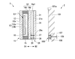
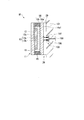
- FIG. 1 is a front view of a solar cell module according to an embodiment of the present invention.
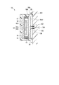
- FIG. 2 is a cross-sectional view of a side surface and a wall portion of the solar cell module.
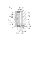
- FIG. 3 is a cross-sectional view illustrating a construction method for the solar cell module.
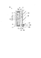
- FIG. 4 is a cross-sectional view of a side surface and a wall portion of a solar cell module according to a modification of the embodiment of the present invention.
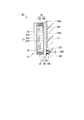
- FIG. 5 is a cross-sectional view of a side surface and a wall portion of a solar cell module according to a modification of the embodiment of the present invention.
- FIG. 1 is a front view of a solar cell module according to an embodiment of the present invention.
- FIG. 2 is a cross-sectional view of a side surface and a wall portion of the solar cell module.
- FIG. 3 is a cross-sectional view illustrating a construction method for the solar cell module.
- FIG. 4 is a cross-sectional view of
- FIG. 6 is a cross-sectional view of a side surface and a wall portion of a solar cell module according to a modification of the embodiment of the present invention.
- FIG. 7 is a cross-sectional view of a side surface and a wall portion of a solar cell module according to a modification of the embodiment of the present invention.
- FIG. 8 is a cross-sectional view of a side surface and a wall portion of a solar cell module according to a modification of the embodiment of the present invention.
- FIG. 9 is a cross-sectional view of a side surface and a wall portion of a solar cell module according to a modification of the embodiment of the present invention.
- FIG. 10 is a cross-sectional view of a side surface and a wall portion of a solar cell module in a modification of the embodiment of the present invention.
- the solar cell module 1 of the present embodiment is opposite to the sheet-like dye-sensitized solar cell 11 and the first surface 12 a that is the light-receiving surface of the dye-sensitized solar cell 11.
- the direction of the dye-sensitized solar cell 11 with respect to the adhesive layer 21 is referred to as a front D1
- the direction of the adhesive layer 21 with respect to the dye-sensitized solar cell 11 is referred to as a rear D2.
- the configuration of the dye-sensitized solar cell 11 is not particularly limited. As shown in FIG. 2, the dye-sensitized solar cell 11 includes, for example, a photoelectrode 13 stacked on a transparent substrate 12, a counter electrode 14, a sealing material 15, and an electrolytic solution 16.
- the transparent substrate 12 is made of, for example, a resin material mainly composed of a transparent thermoplastic resin material such as polyethylene naphthalate (PEN) or polyethylene terephthalate (PET), or glass.
- the front surface D1 of the transparent substrate 12 is the first surface 12a.
- the photoelectrode 13 includes a transparent conductive film 13a and a porous oxide semiconductor layer 13b that is a porous layer.
- the transparent conductive film 13a is formed of a metal oxide such as indium oxide / tin oxide (ITO).
- the porous oxide semiconductor layer 13b is made of, for example, titanium oxide (TiO 2 ). A sensitizing dye and lithium ions or zinc ions are adsorbed on the surface of the porous oxide semiconductor layer 13b.
- the counter electrode 14 has a configuration in which a metal film 14b such as platinum is formed on a counter electrode substrate (substrate) 14a.
- the counter electrode substrate 14 a is formed in the same manner as the transparent substrate 12.
- the configuration of the counter electrode 14 is not limited to this, and a conventionally known counter electrode can be used.
- a metal plate, a conductive substrate, a conductive sheet, or the like can be applied to the counter electrode 14.
- the outer surface of the back D2 of the counter electrode substrate 14a is the second surface 14a1.
- the sealing material 15 has adhered the outer edge part of the photoelectrode 13 and the outer edge part of the counter electrode 14 continuously.
- an adhesive such as a hot melt resin is preferably used.
- a conventionally known solvent is applicable as the solvent constituting the electrolytic solution 16.
- the dye-sensitized solar cell 11 is provided with a positive electrode wiring and a negative electrode wiring (not shown) for taking out the electric power generated between the photoelectrode 13 and the counter electrode 14 to the outside.
- the dye-sensitized solar cell 11 generates power when the visible light L1 passes through the transparent substrate 12 from the first surface 12a and enters the dye-sensitized solar cell 11.
- the counter electrode substrate 14a is formed of a transparent material, either the first surface 12a or the second surface 14a1 of the dye-sensitized solar cell 11 may be used as the light receiving surface.
- the adhesive layer 21 for example, a known pressure-sensitive adhesive tape and a weakly viscous adhesive layer are used.
- the pressure-sensitive adhesive tape may have a structure in which an acrylic or silicone pressure-sensitive adhesive layer is provided on both surfaces of a support formed of a nonwoven fabric or a resin.
- the weakly viscous adhesive layer it is preferable to use Magic Resin (registered trademark, manufactured by Daisho Electronics Co., Ltd.). By using the magic resin as the weakly viscous adhesive layer, the sticky feeling when the solar cell module 1 is attached to the wall 101 described later is eliminated.
- the adhesive layer 21 detachably attaches the dye-sensitized solar cell 11 to the wall (adhered body) 101 by its own adhesive force. That is, the adhesive layer 21 is provided in advance in the solar cell module 1.
- the adhesive layer 21 is a member different from the counter electrode substrate 14a.
- the battery-side conductive portion 26 has a battery-side positive terminal (positive terminal) 27 and a battery-side negative terminal (negative terminal) 28 that are electrically connected to the positive electrode wiring and the negative electrode wiring of the dye-sensitized solar cell 11. More specifically, the battery-side positive terminal 27 is connected to the positive wiring, and the battery-side negative terminal 28 is connected to the negative wiring.
- the terminals 27 and 28 are formed of a conductive material, more specifically, a metal such as phosphor bronze, for example, in a rod shape.
- the base end portions of the terminals 27 and 28 are provided on the second surface 14 a 1 of the dye-sensitized solar cell 11.
- the distal ends of the terminals 27 and 28 are bent with respect to the proximal ends of the terminals 27 and 28 and extend rearward D2.
- a conductive resin such as polyacetylene or polypyrrole may be used as the conductive material for forming the terminals 27 and 28.
- the base end portions of the terminals 27 and 28 may be housed in a housing 29 formed of an electrically insulating resin or the like.
- the outer surface 21a of the adhesive layer 21 opposite to the counter electrode 14 and the outer surface 29a of the housing 29 opposite to the counter electrode 14 are substantially flush with each other.
- the front ends of the terminals 27 and 28 protrude from the housing 29 to the rear D2.
- the battery-side conductive portion 26 is attached to the edge of the second surface 14a1 of the dye-sensitized solar cell 11 with an adhesive (not shown) or the like.
- the position where the battery-side conductive portion 26 is attached to the dye-sensitized solar cell 11 is not limited to this, and the battery-side conductive portion 26 may be attached to the central portion of the second surface 14a1 of the dye-sensitized solar cell 11. .
- the solar cell module 1 includes a release paper (release material) 31 that covers the outer surface of the adhesive layer 21 opposite to the dye-sensitized solar cell 11.
- the release paper 31 has a configuration in which a release layer formed of a silicone resin or the like is provided on a base material formed of, for example, high-quality paper.
- the wall 101 is made of wood or the like.
- the adherend is not limited to the wall portion 101 and may be a ceiling portion, a floor portion, or the like.
- a wall side conductive portion (adhered body side conductive portion) 106 is attached to the outer surface 101 a of the wall portion 101.
- the wall-side conductive portion 106 includes, for example, a cylindrical wall-side positive terminal 107 and a wall-side negative terminal 108. Terminals 27 and 28 are inserted into the terminals 107 and 108. The terminals 107 and 108 are detachable from the terminals 27 and 28.
- the wall side conductive part 106 is detachable from the battery side conductive part 26.
- the wall side conductive portion 106 When the battery side conductive portion 26 is attached to the wall side conductive portion 106, the wall side conductive portion 106 is electrically connected to the battery side conductive portion 26. At this time, the wall-side positive terminal 107 and the battery-side positive terminal 27 are electrically connected, and the wall-side negative terminal 108 and the battery-side negative terminal 28 are electrically connected.
- the wall-side conductive portion 106 is connected to an electronic device such as a storage battery (not shown) via the wiring 109.
- the solar cell module 1, the wall portion 101, and the wall side conductive portion 106 constitute a solar cell system 2.
- the solar cell module 1 configured as described above can be manufactured by a known roll-to-roll method.
- the battery side conductive portion 26 may be attached to the solar cell module 1 by post-processing of a roll-to-roll method.
- the sheet-like solar cell module 1 can be manufactured in large quantities and at low cost.
- the worker P attaches the wall side conductive part 106 to the wall part 101 (conductive part installation process).
- a wiring 109 is provided in the wall portion 101.
- the worker P removes the release paper 31 from the solar cell module 1 (release paper removal step).
- the tip portions of the terminals 27 and 28 are exposed from the solar cell module 1.
- the worker P attaches the adhesive layer 21 of the solar cell module 1 to the wall portion 101 so that the battery-side conductive portion 26 overlaps the wall-side conductive portion 106 (solar cell mounting step).
- the battery-side conductive portion 26 is electrically connected to the wall-side conductive portion 106. Since the solar cell module 1 is provided with the adhesive layer 21 in advance, the solar cell module 1 is easily attached to the wall portion 101 by the adhesive layer 21.
- the second surface 14 a 1 of the dye-sensitized solar cell 11 is the surface closest to the wall portion 101 in the dye-sensitized solar cell 11. Therefore, the length in which the wall side conductive portion 106 and the terminals 27 and 28 of the wall portion 101 are wired is shortened.
- visible light L ⁇ b> 1 is applied to the first surface 12 a of the dye-sensitized solar cell 11, power is generated between the photoelectrode 13 and the counter electrode 14. This electric power is taken out to the outside through the positive and negative wirings and the terminals 27 and 28 and is sent to the electronic device through the terminals 107 and 108 and the wiring 109.
- the adhesive layer 21 is provided in advance on the solar cell module 1. With this adhesive layer 21, the solar cell module 1 can be easily attached to the wall portion 101. Then, the battery side conductive portion 26 can be electrically connected to the wall side conductive portion 106 of the wall portion 101. In other words, since the adhesive layer 21 is already provided on the second surface 14a1 of the dye-sensitized solar cell 11 when the solar cell module 1 is attached to the wall portion 101, the solar cell module 1 is attached to the wall portion 101. When attaching, it is not necessary to attach the adhesive layer 21 to the dye-sensitized solar cell 11 again.
- the solar cell module 1 can be easily attached to the wall portion 101.
- the adhesive layer 21 can be attached to and detached from the wall portion 101 by an adhesive force. Therefore, the solar cell module 1 can be attached to and detached from the wall portion 101 with a simple configuration.
- the battery-side conductive portion 26 has the terminals 27 and 28, the electric power generated in the dye-sensitized solar cell 11 can be taken out through the terminals 27 and 28. Since the terminals 27 and 28 are provided on the second surface 14a1 of the dye-sensitized solar cell 11, the length in which the wall-side conductive portion 106 of the wall portion 101 and the terminals 27 and 28 are wired can be further shortened. it can.
- the solar cell module 1 of the present embodiment can be variously modified in its configuration as described below.
- the battery-side positive terminal 27 is provided on the second surface 14a1 of the dye-sensitized solar cell 11
- the battery-side negative terminal 28 is the second surface 14a1 of the counter electrode substrate 14a. May be provided on the opposite outer surface 14a2 (in other words, the surface facing the opposite side (outside) of the wall portion 101 in the game board 14a).
- the battery-side negative electrode terminal 28 may be formed in advance (in other words, from before the solar cell module 1A is attached to the wall 101) so that the tip thereof extends to the rear D2.
- the battery-side negative electrode terminal 28 may be flat or straight along the outer surface 14a2, as shown by a two-dot chain line in FIG. 4 as a shape S1. .
- the worker P bends so that the tip end portion of the battery-side negative electrode terminal 28 extends rearward D2.
- the tip of the battery-side negative terminal 28 is electrically connected to the wall-side negative terminal 108 of the wall-side conductive portion 106.
- the outer surface 14a2 of the counter electrode substrate 14a is closer to the worker P than the second surface 14a1 of the dye-sensitized solar cell 11.
- the operator P can easily check the battery-side negative terminal 28 by visual observation, and can easily perform processing such as bending the battery-side negative terminal 28.
- the battery-side positive terminal 27 may be provided on the outer surface 14a2 of the counter electrode substrate 14a
- the battery-side negative terminal 28 may be provided on the second surface 14a1 of the counter electrode substrate 14a.
- both of the terminals 27 and 28 may be provided on the outer surface 14a2 of the counter electrode substrate 14a.
- the adhesive layer 21 may contain particles 36 that reflect (scatter) visible light L ⁇ b> 1.
- the particles 36 can be formed of titanium oxide, for example.
- the outer diameter of the particles 36 is preferably about 200 nm to 380 nm which is a half of the wavelength of visible light L1 of about 400 nm (nanometer) to 760 nm.
- part of the visible light L ⁇ b> 1 that is incident on the first surface 12 a of the dye-sensitized solar cell 11 and is transmitted through the dye-sensitized solar cell 11 is reflected by the particles 36.
- the reflected visible light L1 is incident on the dye-sensitized solar cell 11 again.
- the dye-sensitized solar cell 11 can efficiently generate power using the visible light L1 incident on the first surface 12a.
- a reflective sheet 38 that reflects the visible light L ⁇ b> 1 may be disposed between the wall portion 101 and the adhesive layer 21.
- the reflection sheet 38 for example, a sheet formed of a metal such as aluminum can be used.
- the reflection sheet 38 may be attached in advance to the outer surface of the adhesive layer 21 opposite to the dye-sensitized solar cell 11.
- part of the visible light L ⁇ b> 1 transmitted through the dye-sensitized solar cell 11 is reflected by the reflection sheet 38 as described above.
- the reflected visible light L1 is incident on the dye-sensitized solar cell 11 again.
- the dye-sensitized solar cell 11 can efficiently generate power using the visible light L1 incident on the first surface 12a.
- each of the components of the solar cell module 1 may be configured not to include the adhesive layer 21, and the counter electrode substrate 14 c may be formed of a magnetic material such as stainless steel.
- the worker P attaches the permanent magnet 111 to the outer surface 101 a of the wall portion 101.
- a magnetic force acting between the permanent magnet 111 and the counter electrode substrate 14c is used.
- the counter electrode substrate 14c also serves as an attaching / detaching portion. Since the counter electrode substrate 14c also serves as an attaching / detaching portion, the outer shape of the solar cell module 1E can be reduced in size.
- the solar cell module 1 ⁇ / b> F shown in FIG. 9 a configuration in which the adhesive layer 21 is not provided for each configuration of the solar cell module 1 may be adopted. In this case, the frictional force acting between the terminals 107 and 108 and the terminals 27 and 28 inserted into the terminals 107 and 108 is increased to some extent.
- the solar cell module 1 ⁇ / b> F is attached to the wall portion 101 by fitting the terminals 107 and 108 with the terminals 27 and 28.
- the battery-side conductive part 26 also serves as an attaching / detaching part. Since the battery-side conductive portion 26 also serves as an attachment / detachment portion, the outer shape of the solar cell module 1F can be reduced in size.
- a transparent adhesive sheet (detachable portion) 41 may be provided for each component of the solar cell module 1 instead of the adhesive layer 21.
- the adhesive sheet 41 has a central portion that covers the dye-sensitized solar cell 11 and the battery-side conductive portion 26, and an end portion that is attached to the wall portion 101.
- a UV (ultraviolet) cured sheet may be used as the attaching / detaching portion.
- the UV cured sheet is irradiated with ultraviolet rays in a state where the UV cured sheet of the solar cell module 1 is in contact with the wall portion 101, the UV cured sheet is cured. Thereby, the solar cell module 1 can be attached to the wall part 101.
- a UV curable sheet is used for the detachable portion, when the solar cell module 1 is attached to the wall portion 101, a load due to heating does not act on the dye-sensitized solar cell 11.
- the solar cell module 1 may include a suction cup instead of the adhesive layer 21.
- the solar cell module 1 may not include the release paper 31.
- the solar cell module and the solar cell module construction method of the present invention can be easily attached to the adherend and electrically connected to the adherend.
Landscapes
- Engineering & Computer Science (AREA)
- Power Engineering (AREA)
- Microelectronics & Electronic Packaging (AREA)
- Photovoltaic Devices (AREA)
- Hybrid Cells (AREA)
Abstract
Description
本願は、2016年4月27日に、日本に出願された日本国特願2016-089654号に基づき優先権を主張し、その内容をここに援用する。
このように構成された太陽電池モジュールでは、発電された電気はカソード側集電端子から取出される。
特許文献1の太陽電池モジュールでは、被着体に取付けるための着脱部を太陽電池モジュールに取り付けてから、被着体に太陽電池モジュールを取付ける必要がある。被着体において太陽電池モジュールが取付けられる面積は広い場合がある。この場合、太陽電池モジュールに着脱部を取付けるのに多大な労力を要している。
本発明の太陽電池モジュールは、色素増感太陽電池と、前記色素増感太陽電池の受光面である第一の面とは反対側の第二の面に設けられ、前記色素増感太陽電池を被着体に着脱可能に取付ける着脱部と、前記色素増感太陽電池で生じた電力を外部に取出し、前記被着体の被着体側導電部に着脱可能な電池側導電部と、を備える。
この発明によれば、太陽電池モジュールには予め着脱部が設けられている。この着脱部により、被着体に太陽電池モジュールを容易に取付けることができる。そして、電池側導電部を被着体の被着体側導電部に容易に電気的に接続することができる。言い換えると、被着体に太陽電池モジュールを取り付ける際には既に、着脱部が色素増感太陽電池の第二の面に設けられているため、被着体に太陽電池モジュールを取り付ける際に改めて、色素増感太陽電池に着脱部を取り付ける必要が無い。そのため、被着体において太陽電池モジュールが取付けられる面積が広くても、被着体に太陽電池モジュールを容易に取付けることができる。
この発明によれば、被着体に太陽電池モジュールを簡単な構成で着脱させることができる。
また、上記の太陽電池モジュールにおいて、前記色素増感太陽電池は、前記第二の面を有する基板を備えてもよい。前記基板は前記着脱部を兼ねてもよい。
この発明によれば、太陽電池モジュールの外形を小型化することができる。
この発明によれば、色素増感太陽電池で生じた電力を正極端子及び負極端子を通して外部に取出すことができる。
また、上記の太陽電池モジュールにおいて、前記導電性材料は金属又は導電性樹脂であってもよい。
また、上記の太陽電池モジュールにおいて、前記電池側導電部は前記着脱部を兼ねてもよい。
この発明によれば、太陽電池モジュールの外形を小型化することができる。
この発明によれば、作業者が被着体に太陽電池モジュールを取付けたときに、第二の面は色素増感太陽電池のうち被着体に最も近い面となる。したがって、被着体の被着体側導電部及び正極端子及び負極端子の一方が配線される長さを短くすることができる。 また、上記の太陽電池モジュールにおいて、前記色素増感太陽電池は、前記第二の面を有する基板を備えてもよい。前記正極端子及び前記負極端子の一方のみが、前記色素増感太陽電池の前記第二の面に設けられ、前記正極端子及び前記負極端子の他方は、前記基板の前記第二の面とは反対側の外面に設けられていてもよい。 この発明によれば、作業者が被着体に太陽電池モジュールを取付けたときに、基板の外面(言い換えると、基板において被着体の反対側(外側)を向く面)は色素増感太陽電池の第二の面よりも作業者に近くなる。これにより、正極端子及び負極端子の他方を処理する作業を容易に行うことができる。
この発明によれば、正極端子及び負極端子の両方が色素増感太陽電池の第二の面に設けられるため、被着体の被着体側導電部と正極端子及び負極端子とが配線される長さをさらに短くすることができる。
また、上記の太陽電池モジュールにおいて、前記色素増感太陽電池は、前記第二の面を有する基板を備えてもよい。前記正極端子及び前記負極端子は、前記基板の前記第二の面とは反対側の外面に設けられていてもよい。
この発明によれば、正極端子及び負極端子を処理する作業をさらに容易に行うことができる。
この発明によれば、受光面に入射して色素増感太陽電池を透過した可視光線を粒子で反射させて再び色素増感太陽電池に入射させる。これにより、受光面に入射した可視光線を用いて色素増感太陽電池で効率的に発電することができる。
また、本発明の太陽電池モジュールの施工方法は、前記被着体に、上記に記載の太陽電池モジュールの前記着脱部を取付ける。前記被着体の被着体側導電部に前記電池側導電部を電気的に接続する。
この発明によれば、予め着脱部が設けられた太陽電池モジュールを用いて、被着体に太陽電池モジュールを容易に取付けることができる。そして、電池側導電部を被着体の被着体側導電部に電気的に接続することができる。
図1及び図2に示すように、本実施形態の太陽電池モジュール1は、シート状の色素増感太陽電池11と、色素増感太陽電池11の受光面である第一の面12aとは反対側の第二の面14a1に設けられた接着層(着脱部)21と、色素増感太陽電池11で生じた電力を外部に取出すための電池側導電部26とを備えている。
以下では、接着層21に対する色素増感太陽電池11の向きを前方D1と称し、色素増感太陽電池11に対する接着層21の向きを後方D2と称する。
透明基板12は、例えば、ポリエチレンナフタレート(PEN)、ポリエチレンテレフタレート(PET)等の透明の熱可塑性樹脂材料を主材料とする樹脂材料、又はガラスで形成されている。透明基板12の前方D1の面が、第一の面12aである。
封止材15は、光電極13の外縁部と対極14の外縁部とを連続的に貼着している。封止材15としては、接着剤、例えばホットメルト樹脂等が好適に用いられる。
電解液16を構成する溶媒として従来公知の溶媒が適用可能である。電解液16には、リチウム塩又は亜鉛塩の溶解度が低い溶媒を用いることが好ましい。
色素増感太陽電池11は、可視光線L1が第一の面12aから透明基板12を透過して色素増感太陽電池11内に入射することで発電する。
なお、対極基板14aが透明の材料で形成されているときには、色素増感太陽電池11の第一の面12a及び第二の面14a1のいずれを受光面としてもよい。
接着層21は、自身の粘着力により、色素増感太陽電池11を壁部(被着体)101に着脱可能に取付ける。すなわち、太陽電池モジュール1には予め接着層21が設けられている。接着層21は、対極基板14aとは別の部材である。
なお、端子27、28を形成する導電性材料として、ポリアセチレン、ポリピロール等の導電性樹脂を用いてもよい。
接着層21の対極14とは反対側の外面21aと、ハウジング29の対極14とは反対側の外面29aとは、ほぼ面一である。端子27、28の先端部は、ハウジング29から後方D2に突出している。
壁部101の外面101aには、壁側導電部(被着体側導電部)106が取付けられている。壁側導電部106は、例えば筒状の壁側正極端子107及び壁側負極端子108を有している。端子107、108内に端子27、28が挿入される。端子107、108は端子27、28と着脱可能である。壁側導電部106は、電池側導電部26と着脱可能である。壁側導電部106に電池側導電部26を取付けると、壁側導電部106が電池側導電部26と電気的に接続される。このとき、壁側正極端子107と電池側正極端子27とが電気的に接続され、壁側負極端子108と電池側負極端子28とが電気的に接続される。
壁側導電部106は、配線109を介して、図示しない蓄電池等の電子機器に接続されている。
なお、太陽電池モジュール1、壁部101、及び壁側導電部106で、太陽電池システム2を構成する。
ロール・トゥ・ロール方式により製造することで、シート状の太陽電池モジュール1を多量かつ安価に製造することができる。
まず、作業者Pは壁部101に壁側導電部106を取付ける(導電部設置工程)。壁部101内に配線109を設ける。
次に、図3に示すように、作業者Pは太陽電池モジュール1から剥離紙31を取外す(剥離紙除去工程)。このとき、太陽電池モジュール1から端子27、28の先端部が露出する。
次に、作業者Pは壁側導電部106に電池側導電部26を重ねるように、壁部101に太陽電池モジュール1の接着層21を取付ける(太陽電池取付け工程)。このとき、壁側導電部106に電池側導電部26が電気的に接続される。太陽電池モジュール1には予め接着層21が設けられているため、この接着層21により、壁部101に太陽電池モジュール1が容易に取付けられる。
色素増感太陽電池11の第一の面12aに可視光線L1が照射されると、光電極13と対極14との間で電力が生じる。この電力は、正極配線及び負極配線、及び端子27、28を通して外部に取出され、端子107、108、及び配線109を介して電子機器に送られる。
このように、太陽電池モジュール1の施工を簡単に行うことができる。
接着層21は、粘着力により壁部101に着脱可能である。したがって、壁部101に太陽電池モジュール1を簡単な構成で着脱させることができる。
図4に示す太陽電池モジュール1Aのように、電池側正極端子27が色素増感太陽電池11の第二の面14a1に設けられるとともに、電池側負極端子28が対極基板14aの第二の面14a1とは反対側の外面14a2(言い換えると、対局基板14aにおいて壁部101の反対側(外側)を向く面)に設けられていてもよい。
電池側負極端子28は、予め(言い換えると、太陽電池モジュール1Aを壁部101に取付ける前から)その先端部が後方D2に延びるように形成してもよい。また、壁部101に取付ける前の太陽電池モジュール1Aでは、電池側負極端子28は図4に二点鎖線で形状S1として示すように、外面14a2に沿った平坦状又は直線状であってもよい。この場合、作業者Pは壁部101に太陽電池モジュール1Aを取付けた後で、電池側負極端子28の先端部が後方D2に延びるように折り曲げる。壁側導電部106の壁側負極端子108に電池側負極端子28の先端部を、電気的に接続させる。
なお、本変形例では、電池側正極端子27が対極基板14aの外面14a2に設けられるとともに、電池側負極端子28が対極基板14aの第二の面14a1に設けられるように構成してもよい。
このように構成することで、作業者Pが端子27、28を目視により確認しやすくなり、端子27、28を処理する作業をさらに容易に行うことができる。
このように構成された太陽電池モジュール1Cでは、色素増感太陽電池11の第一の面12aに入射して色素増感太陽電池11を透過した可視光線L1の一部は、粒子36で反射される。この反射された可視光線L1が再び色素増感太陽電池11に入射する。
これにより、第一の面12aに入射した可視光線L1を用いて色素増感太陽電池11で効率的に発電することができる。
反射シート38は、接着層21の色素増感太陽電池11とは反対側の外面に予め貼り付けられていてもよい。
このように構成された太陽電池モジュール1Dでは、前述のように色素増感太陽電池11を透過した可視光線L1の一部は、反射シート38で反射される。この反射された可視光線L1が再び色素増感太陽電池11に入射する。
これにより、第一の面12aに入射した可視光線L1を用いて色素増感太陽電池11で効率的に発電することができる。
作業者Pが壁部101に太陽電池モジュール1Eを取付けるときには、永久磁石111と対極基板14cとの間に作用する磁力を用いる。この場合、対極基板14cは着脱部を兼ねる。
対極基板14cが着脱部を兼ねることで、太陽電池モジュール1Eの外形を小型化することができる。
電池側導電部26が着脱部を兼ねることで、太陽電池モジュール1Fの外形を小型化することができる。
例えば、前記実施形態では、着脱部としてUV(紫外線)硬化シートを用いてもよい。壁部101に太陽電池モジュール1のUV硬化シートを接触させた状態で、UV硬化シートに紫外線を照射すると、UV硬化シートが硬化する。これにより、壁部101に太陽電池モジュール1を取付けることができる。着脱部にUV硬化シートを用いると、壁部101に太陽電池モジュール1を取付けるときに、色素増感太陽電池11に加熱による負荷が作用しない。
11 色素増感太陽電池
12a 第一の面
14a、14c 対極基板(基板)
14a1 第二の面
14a2 外面
26 第一の導電部(導電部)
27 電池側正極端子(正極端子)
28 電池側負極端子(負極端子)
36 粒子
41 粘着シート(着脱部)
101 壁部(被着体)
Claims (14)
- 色素増感太陽電池と、
前記色素増感太陽電池の受光面である第一の面とは反対側の第二の面に設けられ、前記色素増感太陽電池を被着体に着脱可能に取付ける着脱部と、
前記色素増感太陽電池で生じた電力を外部に取出し、前記被着体の被着体側導電部に着脱可能な電池側導電部と、
を備える太陽電池モジュール。 - 前記着脱部は、粘着力、磁力、及び嵌め合わせの少なくとも1つにより前記被着体に着脱可能である請求項1に記載の太陽電池モジュール。
- 前記色素増感太陽電池は、前記第二の面を有する基板を備え、
前記着脱部は前記基板とは別の部材である請求項1に記載の太陽電池モジュール。 - 前記色素増感太陽電池は、前記第二の面を有する基板を備え、
前記基板は前記着脱部を兼ねる請求項1に記載の太陽電池モジュール。 - 前記電池側導電部は、前記色素増感太陽電池に電気的に接続された正極端子及び負極端子を有する請求項1に記載の太陽電池モジュール。
- 前記電池側導電部は導電性材料で形成されている請求項1に記載の太陽電池モジュール。
- 前記導電性材料は金属又は導電性樹脂である請求項6に記載の太陽電池モジュール。
- 前記電池側導電部は前記着脱部を兼ねる請求項1から7のいずれか一項に記載の太陽電池モジュール。
- 前記正極端子及び前記負極端子の少なくとも一方は、前記色素増感太陽電池の前記第二の面に設けられている請求項5に記載の太陽電池モジュール。
- 前記色素増感太陽電池は、前記第二の面を有する基板を備え、
前記正極端子及び前記負極端子の一方のみが、前記色素増感太陽電池の前記第二の面に設けられ、前記正極端子及び前記負極端子の他方は、前記基板の前記第二の面とは反対側の外面に設けられている請求項9に記載の太陽電池モジュール。 - 前記正極端子及び前記負極端子の両方が、前記色素増感太陽電池の前記第二の面に設けられている請求項9に記載の太陽電池モジュール。
- 前記色素増感太陽電池は、前記第二の面を有する基板を備え、
前記正極端子及び前記負極端子は、前記基板の前記第二の面とは反対側の外面に設けられている請求項5に記載の太陽電池モジュール。 - 前記着脱部は接着層であり、
前記接着層は可視光線を反射する粒子を含有している請求項1に記載の太陽電池モジュール。 - 前記被着体に、請求項1に記載の太陽電池モジュールの前記着脱部を取付け、
前記被着体の被着体側導電部に前記電池側導電部を電気的に接続する太陽電池モジュールの施工方法。
Priority Applications (3)
| Application Number | Priority Date | Filing Date | Title |
|---|---|---|---|
| KR1020187025657A KR20180136437A (ko) | 2016-04-27 | 2017-04-26 | 태양 전지 모듈 및 태양 전지 모듈의 시공 방법 |
| JP2018514650A JPWO2017188291A1 (ja) | 2016-04-27 | 2017-04-26 | 太陽電池モジュール及び太陽電池モジュールの施工方法 |
| CN201780014852.8A CN108713234A (zh) | 2016-04-27 | 2017-04-26 | 太阳能电池模块及太阳能电池模块的施工方法 |
Applications Claiming Priority (2)
| Application Number | Priority Date | Filing Date | Title |
|---|---|---|---|
| JP2016089654 | 2016-04-27 | ||
| JP2016-089654 | 2016-04-27 |
Publications (1)
| Publication Number | Publication Date |
|---|---|
| WO2017188291A1 true WO2017188291A1 (ja) | 2017-11-02 |
Family
ID=60159667
Family Applications (1)
| Application Number | Title | Priority Date | Filing Date |
|---|---|---|---|
| PCT/JP2017/016459 Ceased WO2017188291A1 (ja) | 2016-04-27 | 2017-04-26 | 太陽電池モジュール及び太陽電池モジュールの施工方法 |
Country Status (5)
| Country | Link |
|---|---|
| JP (1) | JPWO2017188291A1 (ja) |
| KR (1) | KR20180136437A (ja) |
| CN (1) | CN108713234A (ja) |
| TW (1) | TW201803175A (ja) |
| WO (1) | WO2017188291A1 (ja) |
Cited By (1)
| Publication number | Priority date | Publication date | Assignee | Title |
|---|---|---|---|---|
| JP2022104016A (ja) * | 2020-12-28 | 2022-07-08 | 太陽誘電株式会社 | 太陽電池モジュールおよびその製造方法 |
Families Citing this family (1)
| Publication number | Priority date | Publication date | Assignee | Title |
|---|---|---|---|---|
| JP7273972B2 (ja) * | 2019-07-29 | 2023-05-15 | シャープ株式会社 | 太陽電池付電子機器 |
Citations (3)
| Publication number | Priority date | Publication date | Assignee | Title |
|---|---|---|---|---|
| JP2009238484A (ja) * | 2008-03-26 | 2009-10-15 | Nissha Printing Co Ltd | 太陽電池付きシートおよび太陽電池付き成形品の製造方法 |
| JP2010153646A (ja) * | 2008-12-25 | 2010-07-08 | Asahi Kasei Chemicals Corp | 外部刺激により接着硬化するプリプレグシートを備えた太陽光発電モジュール、及びその設置方法 |
| JP2012227457A (ja) * | 2011-04-22 | 2012-11-15 | Three M Innovative Properties Co | 電気化学キャパシタ |
Family Cites Families (4)
| Publication number | Priority date | Publication date | Assignee | Title |
|---|---|---|---|---|
| JP2005222995A (ja) * | 2004-02-03 | 2005-08-18 | Sekisui Jushi Co Ltd | 太陽電池モジュール |
| JP2010211971A (ja) * | 2009-03-09 | 2010-09-24 | Citizen Holdings Co Ltd | 色素増感太陽電池およびそれを備えた腕時計 |
| JP5427863B2 (ja) * | 2011-09-30 | 2014-02-26 | 太陽誘電株式会社 | 太陽電池セル |
| CN102569467B (zh) * | 2012-03-13 | 2015-08-12 | 北京东方雨虹防水技术股份有限公司 | 一种自粘型模块化的晶体硅太阳能电池组件 |
-
2017
- 2017-04-25 TW TW106113759A patent/TW201803175A/zh unknown
- 2017-04-26 CN CN201780014852.8A patent/CN108713234A/zh active Pending
- 2017-04-26 KR KR1020187025657A patent/KR20180136437A/ko not_active Withdrawn
- 2017-04-26 WO PCT/JP2017/016459 patent/WO2017188291A1/ja not_active Ceased
- 2017-04-26 JP JP2018514650A patent/JPWO2017188291A1/ja active Pending
Patent Citations (3)
| Publication number | Priority date | Publication date | Assignee | Title |
|---|---|---|---|---|
| JP2009238484A (ja) * | 2008-03-26 | 2009-10-15 | Nissha Printing Co Ltd | 太陽電池付きシートおよび太陽電池付き成形品の製造方法 |
| JP2010153646A (ja) * | 2008-12-25 | 2010-07-08 | Asahi Kasei Chemicals Corp | 外部刺激により接着硬化するプリプレグシートを備えた太陽光発電モジュール、及びその設置方法 |
| JP2012227457A (ja) * | 2011-04-22 | 2012-11-15 | Three M Innovative Properties Co | 電気化学キャパシタ |
Cited By (2)
| Publication number | Priority date | Publication date | Assignee | Title |
|---|---|---|---|---|
| JP2022104016A (ja) * | 2020-12-28 | 2022-07-08 | 太陽誘電株式会社 | 太陽電池モジュールおよびその製造方法 |
| JP7672221B2 (ja) | 2020-12-28 | 2025-05-07 | 太陽誘電株式会社 | 太陽電池モジュール |
Also Published As
| Publication number | Publication date |
|---|---|
| TW201803175A (zh) | 2018-01-16 |
| CN108713234A (zh) | 2018-10-26 |
| KR20180136437A (ko) | 2018-12-24 |
| JPWO2017188291A1 (ja) | 2019-03-07 |
Similar Documents
| Publication | Publication Date | Title |
|---|---|---|
| US11463039B2 (en) | Energy harvester | |
| CN217881815U (zh) | 采样组件及电池模组 | |
| JPWO2017188291A1 (ja) | 太陽電池モジュール及び太陽電池モジュールの施工方法 | |
| WO2019188433A1 (ja) | 環境発電体 | |
| BRPI0905925B1 (pt) | Método de fabricação de célula solar de silício | |
| JP6777437B2 (ja) | 太陽電池モジュール、太陽電池モジュール巻回体及び太陽電池装着物 | |
| CN112019155B (zh) | 光电转换模块和光电转换模块阵列 | |
| JP2005116324A (ja) | 複合電池およびこれを含む電子機器 | |
| CN101154692B (zh) | 光电转换元件及其制造方法 | |
| CN103035413A (zh) | 太阳能电池单元 | |
| WO2016163123A1 (ja) | 光電変換装置 | |
| JP6801650B2 (ja) | 光電変換装置 | |
| JP6311837B2 (ja) | 光電変換装置 | |
| CN103560154A (zh) | 背接触太阳能电池组件 | |
| JP6975859B2 (ja) | 太陽電池ユニットおよび太陽電池ユニットを備えた無線発信機 | |
| CN111052597B (zh) | 环境发电装置 | |
| JP6931645B2 (ja) | 太陽電池システム、及び太陽電池システムの施工方法 | |
| TW201205238A (en) | Protective kit with solar cells | |
| US20110124382A1 (en) | Mobile phone | |
| US20220254574A1 (en) | Photoelectric conversion device | |
| WO2021020176A1 (ja) | 太陽電池付電子機器 | |
| WO2021020178A1 (ja) | 太陽電池付電子機器 | |
| WO2021020177A1 (ja) | 太陽電池付電子機器 | |
| KR20140004834A (ko) | 휴대폰등 각종 디스플레이장치의 커버글라스에 염료감응형태양전지를 코팅하여 해당전자기기의 전원공급장치로 사용하는 방법 |
Legal Events
| Date | Code | Title | Description |
|---|---|---|---|
| ENP | Entry into the national phase |
Ref document number: 20187025657 Country of ref document: KR Kind code of ref document: A |
|
| WWE | Wipo information: entry into national phase |
Ref document number: 2018514650 Country of ref document: JP |
|
| NENP | Non-entry into the national phase |
Ref country code: DE |
|
| 121 | Ep: the epo has been informed by wipo that ep was designated in this application |
Ref document number: 17789573 Country of ref document: EP Kind code of ref document: A1 |
|
| 122 | Ep: pct application non-entry in european phase |
Ref document number: 17789573 Country of ref document: EP Kind code of ref document: A1 |