WO2017188170A1 - 成膜用マスク及び成膜装置 - Google Patents
成膜用マスク及び成膜装置 Download PDFInfo
- Publication number
- WO2017188170A1 WO2017188170A1 PCT/JP2017/016144 JP2017016144W WO2017188170A1 WO 2017188170 A1 WO2017188170 A1 WO 2017188170A1 JP 2017016144 W JP2017016144 W JP 2017016144W WO 2017188170 A1 WO2017188170 A1 WO 2017188170A1
- Authority
- WO
- WIPO (PCT)
- Prior art keywords
- pair
- peripheral edge
- portions
- axial direction
- plate portions
- Prior art date
- Legal status (The legal status is an assumption and is not a legal conclusion. Google has not performed a legal analysis and makes no representation as to the accuracy of the status listed.)
- Ceased
Links
Images


Classifications
-
- C—CHEMISTRY; METALLURGY
- C23—COATING METALLIC MATERIAL; COATING MATERIAL WITH METALLIC MATERIAL; CHEMICAL SURFACE TREATMENT; DIFFUSION TREATMENT OF METALLIC MATERIAL; COATING BY VACUUM EVAPORATION, BY SPUTTERING, BY ION IMPLANTATION OR BY CHEMICAL VAPOUR DEPOSITION, IN GENERAL; INHIBITING CORROSION OF METALLIC MATERIAL OR INCRUSTATION IN GENERAL
- C23C—COATING METALLIC MATERIAL; COATING MATERIAL WITH METALLIC MATERIAL; SURFACE TREATMENT OF METALLIC MATERIAL BY DIFFUSION INTO THE SURFACE, BY CHEMICAL CONVERSION OR SUBSTITUTION; COATING BY VACUUM EVAPORATION, BY SPUTTERING, BY ION IMPLANTATION OR BY CHEMICAL VAPOUR DEPOSITION, IN GENERAL
- C23C14/00—Coating by vacuum evaporation, by sputtering or by ion implantation of the coating forming material
- C23C14/04—Coating on selected surface areas, e.g. using masks
-
- C—CHEMISTRY; METALLURGY
- C23—COATING METALLIC MATERIAL; COATING MATERIAL WITH METALLIC MATERIAL; CHEMICAL SURFACE TREATMENT; DIFFUSION TREATMENT OF METALLIC MATERIAL; COATING BY VACUUM EVAPORATION, BY SPUTTERING, BY ION IMPLANTATION OR BY CHEMICAL VAPOUR DEPOSITION, IN GENERAL; INHIBITING CORROSION OF METALLIC MATERIAL OR INCRUSTATION IN GENERAL
- C23C—COATING METALLIC MATERIAL; COATING MATERIAL WITH METALLIC MATERIAL; SURFACE TREATMENT OF METALLIC MATERIAL BY DIFFUSION INTO THE SURFACE, BY CHEMICAL CONVERSION OR SUBSTITUTION; COATING BY VACUUM EVAPORATION, BY SPUTTERING, BY ION IMPLANTATION OR BY CHEMICAL VAPOUR DEPOSITION, IN GENERAL
- C23C16/00—Chemical coating by decomposition of gaseous compounds, without leaving reaction products of surface material in the coating, i.e. chemical vapour deposition [CVD] processes
- C23C16/04—Coating on selected surface areas, e.g. using masks
- C23C16/042—Coating on selected surface areas, e.g. using masks using masks
-
- C—CHEMISTRY; METALLURGY
- C23—COATING METALLIC MATERIAL; COATING MATERIAL WITH METALLIC MATERIAL; CHEMICAL SURFACE TREATMENT; DIFFUSION TREATMENT OF METALLIC MATERIAL; COATING BY VACUUM EVAPORATION, BY SPUTTERING, BY ION IMPLANTATION OR BY CHEMICAL VAPOUR DEPOSITION, IN GENERAL; INHIBITING CORROSION OF METALLIC MATERIAL OR INCRUSTATION IN GENERAL
- C23C—COATING METALLIC MATERIAL; COATING MATERIAL WITH METALLIC MATERIAL; SURFACE TREATMENT OF METALLIC MATERIAL BY DIFFUSION INTO THE SURFACE, BY CHEMICAL CONVERSION OR SUBSTITUTION; COATING BY VACUUM EVAPORATION, BY SPUTTERING, BY ION IMPLANTATION OR BY CHEMICAL VAPOUR DEPOSITION, IN GENERAL
- C23C14/00—Coating by vacuum evaporation, by sputtering or by ion implantation of the coating forming material
- C23C14/04—Coating on selected surface areas, e.g. using masks
- C23C14/042—Coating on selected surface areas, e.g. using masks using masks
-
- C—CHEMISTRY; METALLURGY
- C23—COATING METALLIC MATERIAL; COATING MATERIAL WITH METALLIC MATERIAL; CHEMICAL SURFACE TREATMENT; DIFFUSION TREATMENT OF METALLIC MATERIAL; COATING BY VACUUM EVAPORATION, BY SPUTTERING, BY ION IMPLANTATION OR BY CHEMICAL VAPOUR DEPOSITION, IN GENERAL; INHIBITING CORROSION OF METALLIC MATERIAL OR INCRUSTATION IN GENERAL
- C23C—COATING METALLIC MATERIAL; COATING MATERIAL WITH METALLIC MATERIAL; SURFACE TREATMENT OF METALLIC MATERIAL BY DIFFUSION INTO THE SURFACE, BY CHEMICAL CONVERSION OR SUBSTITUTION; COATING BY VACUUM EVAPORATION, BY SPUTTERING, BY ION IMPLANTATION OR BY CHEMICAL VAPOUR DEPOSITION, IN GENERAL
- C23C16/00—Chemical coating by decomposition of gaseous compounds, without leaving reaction products of surface material in the coating, i.e. chemical vapour deposition [CVD] processes
- C23C16/04—Coating on selected surface areas, e.g. using masks
-
- C—CHEMISTRY; METALLURGY
- C23—COATING METALLIC MATERIAL; COATING MATERIAL WITH METALLIC MATERIAL; CHEMICAL SURFACE TREATMENT; DIFFUSION TREATMENT OF METALLIC MATERIAL; COATING BY VACUUM EVAPORATION, BY SPUTTERING, BY ION IMPLANTATION OR BY CHEMICAL VAPOUR DEPOSITION, IN GENERAL; INHIBITING CORROSION OF METALLIC MATERIAL OR INCRUSTATION IN GENERAL
- C23C—COATING METALLIC MATERIAL; COATING MATERIAL WITH METALLIC MATERIAL; SURFACE TREATMENT OF METALLIC MATERIAL BY DIFFUSION INTO THE SURFACE, BY CHEMICAL CONVERSION OR SUBSTITUTION; COATING BY VACUUM EVAPORATION, BY SPUTTERING, BY ION IMPLANTATION OR BY CHEMICAL VAPOUR DEPOSITION, IN GENERAL
- C23C16/00—Chemical coating by decomposition of gaseous compounds, without leaving reaction products of surface material in the coating, i.e. chemical vapour deposition [CVD] processes
- C23C16/44—Chemical coating by decomposition of gaseous compounds, without leaving reaction products of surface material in the coating, i.e. chemical vapour deposition [CVD] processes characterised by the method of coating
- C23C16/50—Chemical coating by decomposition of gaseous compounds, without leaving reaction products of surface material in the coating, i.e. chemical vapour deposition [CVD] processes characterised by the method of coating using electric discharges
-
- H—ELECTRICITY
- H05—ELECTRIC TECHNIQUES NOT OTHERWISE PROVIDED FOR
- H05H—PLASMA TECHNIQUE; PRODUCTION OF ACCELERATED ELECTRICALLY-CHARGED PARTICLES OR OF NEUTRONS; PRODUCTION OR ACCELERATION OF NEUTRAL MOLECULAR OR ATOMIC BEAMS
- H05H1/00—Generating plasma; Handling plasma
- H05H1/24—Generating plasma
- H05H1/46—Generating plasma using applied electromagnetic fields, e.g. high frequency or microwave energy
Definitions
- the present invention relates to a film forming mask used in a film forming apparatus such as a plasma CVD apparatus and a film forming apparatus including the same.
- Patent Document 1 discloses a vacuum processing apparatus that includes a mask that faces a peripheral portion of a glass substrate disposed on a heating plate, and a mask support that supports the mask so as to be movable up and down in a processing chamber. Yes.
- the size of the mask arranged on the peripheral edge of the substrate has also increased, and it is becoming difficult to maintain the mask opening shape with high accuracy.
- the mask opening shape changes due to the difference in the amount of heat input between the inner peripheral side of the mask close to the heating plate and the outer peripheral side opposite to the mask.
- the shape accuracy of the film edge is deteriorated.
- the mask may be damaged due to a stress difference between the inner peripheral side and the outer peripheral side of the mask.
- an object of the present invention is to provide a film forming mask capable of maintaining the shape accuracy of the film edge at the peripheral edge of the substrate and a film forming apparatus including the same.
- a film formation mask includes a pair of first plate portions and a pair of second plate portions.
- the pair of first plate portions includes a pair of first inner peripheral edge portions and a pair of first outer peripheral edge portions.
- the pair of first inner peripheral edge portions have first curved portions that are opposed to each other in the first axial direction and are convex in a direction away from each other.
- the pair of first outer peripheral edges oppose the pair of first inner peripheral edges in the first axial direction, respectively.
- the pair of second plate portions includes a pair of second inner peripheral edge portions and a pair of second outer peripheral edge portions.
- the pair of second inner peripheral edge portions respectively have second curved portions that are opposed to the second axial direction and are convex in a direction away from each other.
- the pair of second outer peripheral edges oppose the pair of second inner peripheral edges in the second axial direction, respectively.
- the inner peripheral edge portions of the first and second plate portions have first and second curved portions that are convex in the directions away from each other.
- thermal expansion thermal elongation
- the first and second curved portions are deformed so as to have a linear shape. This makes it possible to maintain the shape accuracy of the film edge on the peripheral edge of the substrate.
- the pair of first plate portions are provided on the pair of first outer peripheral edge portions, respectively, and are arranged at intervals in a second axial direction orthogonal to the first axial direction. You may further have a notch part.
- the pair of second plate portions further includes a plurality of second cutout portions provided on the pair of second outer peripheral edge portions and spaced apart in the first axial direction. You may have. This facilitates deformation of the outer peripheral edge accompanying thermal deformation of the inner peripheral edge, thereby preventing the first and second plate portions from being damaged.
- the pair of first plate portions and the pair of second plate portions may each be composed of a single plate member. Thereby, the mutual interference between the 1st board part and the 2nd board part at the time of heat input can be controlled.
- Both end portions of the pair of first plate portions may be overlapped with both end portions of the pair of second plate portions. Thereby, separation of the first and second plate portions can be prevented, and a predetermined integral relationship between these plate portions can be maintained.
- the pair of first plate portions and the pair of second plate portions are typically made of a ceramic material.
- a film formation apparatus includes a chamber, a stage, a film formation source, and a mask.
- the stage is disposed inside the vacuum chamber and supports the substrate in a heatable manner.
- the film formation source is disposed to face the stage.
- the mask is disposed around the stage and covers the peripheral edge of the substrate from the film forming source.
- the mask has a pair of first plate portions and a pair of second plate portions.
- the pair of first plate portions includes a pair of first inner peripheral edge portions and a pair of first outer peripheral edge portions.
- the pair of first inner peripheral edge portions have first curved portions that are opposed to each other in the first axial direction and are convex in a direction away from each other.
- the pair of first outer peripheral edges oppose the pair of first inner peripheral edges in the first axial direction, respectively.
- the pair of second plate portions includes a pair of second inner peripheral edge portions and a pair of second outer peripheral edge portions.
- the pair of second inner peripheral edge portions respectively have second curved portions that are opposed to the second axial direction and are convex in a direction away from each other.
- the pair of second outer peripheral edges oppose the pair of second inner peripheral edges in the second axial direction, respectively.
- the pair of first plate portions are provided on the pair of first outer peripheral edge portions, respectively, and are arranged at intervals in a second axial direction orthogonal to the first axial direction. You may further have a notch part.
- the pair of second plate portions further includes a plurality of second cutout portions provided on the pair of second outer peripheral edge portions and spaced apart in the first axial direction. You may have.
- the film forming apparatus may further include a mask support member that can support the mask.
- the mask support member is provided around the stage and has a support portion that allows thermal expansion of the mask in a plane parallel to the first and second axial directions.
- the pair of first plate portions may have a first main through hole and a pair of first auxiliary through holes.
- the first main through hole has a long axis parallel to the first axial direction.
- the pair of first auxiliary through holes have a long axis parallel to the second axial direction, and are opposed to each other in the second axial direction with the first main through hole interposed therebetween.
- the support part includes a plurality of first positioning pins. The plurality of first positioning pins are inserted into the first main through hole and the pair of first auxiliary through holes, respectively, and are relatively movable with respect to the pair of first plate portions.
- the pair of second plate portions may include a second main through hole and a pair of second auxiliary through holes.
- the second main through hole has a long axis parallel to the second axial direction.
- the pair of second auxiliary through holes have a long axis parallel to the first axial direction and face each other in the first axial direction with the second main through hole interposed therebetween.
- the support part includes a plurality of second positioning pins. The plurality of second positioning pins are inserted through the second main through hole and the pair of second auxiliary through holes, respectively, and are relatively movable with respect to the pair of second plate portions.
- the shape accuracy of the film edge at the peripheral edge of the substrate can be maintained.
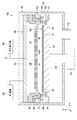
- FIG. 1 is a schematic side sectional view showing a film forming apparatus according to an embodiment of the present invention
- FIG. 2 is a schematic side sectional view showing an operation example of the film forming apparatus.
- the X axis, the Y axis, and the Z axis indicate three axial directions orthogonal to each other.
- the X axis and the Y axis correspond to the horizontal direction
- the Z axis corresponds to the height direction.
- the film forming apparatus 100 is configured as a plasma CVD apparatus.
- the film forming apparatus 100 includes a vacuum chamber 10, a stage 20, a gas head 30, and a mask 40.
- the vacuum chamber 10 has a film forming chamber 11 inside.
- the vacuum chamber 10 has an exhaust port 12 that communicates with a vacuum pump (not shown) that can exhaust and maintain the film forming chamber 11 in a predetermined reduced-pressure atmosphere.
- a first flange portion 13 that supports the gas head 30, a second flange portion 14 that can support the mask 40 at the lowered position of the stage 20 (FIG. 2), and the like are provided on the inner peripheral surface of the vacuum chamber 10. Yes.
- the vacuum chamber 10 is made of a metal material such as stainless steel and is connected to a ground potential.
- the vacuum chamber 10 is provided with a gate valve through which the substrate W transported between the outside and the inside of the vacuum chamber 10 can pass.
- the substrate W is carried in and out in the horizontal direction via a transfer robot (not shown) at the lowered position of the stage 20.
- the substrate W a rectangular glass substrate is typically used.
- the size of the substrate W is not particularly limited, and for example, a substrate of G5 or more (the length of one side is 1000 mm or more) is used, and in this embodiment, a G6 substrate (1850 mm ⁇ 1500 mm) is used.
- the stage 20 has a support surface 21 that supports the substrate W that is a film formation target.
- the support surface 21 is a rectangular plane having a larger area than the substrate W.
- the stage 20 contains a heating source capable of heating the entire support surface 21 to a predetermined temperature.
- the heating source is not particularly limited, and typically includes a heater, a heating medium circulation passage, and the like.
- a support base 22 made of a heat-resistant material that supports the bottom surface of the mask 40 is provided on the periphery of the support surface 21.
- the support base 22 is disposed around the substrate W placed on the support surface 21, and has a height (thickness) at which the mask 40 can be disposed oppositely with a predetermined gap immediately above the peripheral edge of the substrate W.
- the support base 22 may be composed of a plurality of pad members arranged around the substrate W at intervals, or may be composed of an annular body surrounding the substrate W.
- the stage 20 has an elevating shaft 23 and is configured to be movable up and down in the Z-axis direction by an elevating unit 24 installed outside the bottom of the vacuum chamber 10.
- the elevating shaft 23 is fixed at the center of the bottom of the stage 20 and penetrates the bottom wall of the vacuum chamber 10 in an airtight manner.
- the stage 20 is configured to be able to move up and down between a raised position shown in FIG. 1 and a lowered position shown in FIG.
- the stage 20 is connected to the ground potential via the vacuum chamber 10.
- the gas head 30 is disposed inside the vacuum chamber 10 and at a position facing the support surface 21 of the stage 20.
- the gas head 30 constitutes a film formation source for introducing a process gas for film formation into the film formation chamber 11.
- the gas head 30 is typically made of a metal material, and includes a shower plate 31, an annular peripheral wall portion 32, and a top plate portion 33.
- the peripheral wall portion 32 supports the peripheral edge portion of the shower plate 31.
- the top plate portion 33 is connected to the upper end of the peripheral wall portion 32, and forms a gas space 34 between the top plate portion 33 and the shower plate 31.
- the gas head 30 is supported by a first flange portion 13 provided on the inner peripheral surface of the vacuum chamber 10 via an annular insulating member 35.
- a gas introduction line 37 communicating with a gas introduction source 36 is connected to the top plate portion 33 of the gas head 30.
- the gas introduction line 37 penetrates the top plate portion 33 and introduces a predetermined process gas into the gas space 34.
- the gas introduction line 37 includes an on-off valve, a flow control valve, and the like.
- the process gas is not particularly limited, and can be set as appropriate according to the type of material to be deposited. For example, a mixed gas of a source gas such as silane and a reaction gas containing ammonia and nitrogen is used.
- an RF power source 38 is connected to the top plate portion 33 of the gas head 30.
- the RF power source 38 applies high frequency power to the gas head 30, and forms process gas plasma in the film forming chamber 11 between the shower plate 31 and the stage 20.
- the high frequency power applied from the RF power source 38 is not particularly limited, and is, for example, 100 W to 10 kW.
- the mask 40 is arranged around the stage 20 and is configured by a frame that can cover the peripheral edge of the substrate W from the gas head 30.
- the mask 40 is disposed to face the non-film formation region at the peripheral edge of the substrate W, and has a substantially rectangular opening 40a that defines the film formation region. Details of the mask 40 will be described below.
- FIG. 3 is a schematic plan view showing the configuration of the mask 40.
- the mask 40 is configured by a substantially rectangular frame as viewed from above, and has a size capable of covering the peripheral edge of the G6 size substrate W.
- the mask 40 includes a pair of long side plate portions 41A and 41B (first plate portion) and a pair of short side plate portions 42A and 42B (second plate portion).
- the long side plate portions 41A and 41B and the short side plate portions 42A and 42B are typically made of a ceramic material such as alumina or zirconia from the viewpoint of heat resistance, plasma resistance, and corrosion resistance.
- the long side plate portions 41A and 41B have the same configuration, and have an inner peripheral edge portion 411 (first inner peripheral edge portion) and an outer peripheral edge portion 412 (first outer peripheral edge portion).
- the inner peripheral edge portion 411 of each of the long side plate portions 41A and 41B has a curved portion 411w (first curved portion) that is opposed to the X-axis direction and protrudes in a direction away from each other. That is, the curved portion 411w of one long side plate portion 41A has a partial arc shape with a predetermined curvature having an apex on the upper side in FIG. 3, and the curved portion 411w of the other long side plate portion 41B in FIG. It has a partial arc shape with a predetermined curvature having a vertex on the lower side.
- each curved portion 411w is formed with a constant curvature over the entire inner peripheral edge portion 411 of the long side plate portions 41A and 41B, but is not limited to this, and is a complex shape in which arcs of different curvatures are continuous. It may be.
- the curvature radius of each curved portion 411w is appropriately set according to the lengths and linear expansion coefficients of the long side plate portions 41A and 41B, the heating temperature of the substrate W by the stage 20, and the like. In the present embodiment, the radius of curvature of the curved portion 411w is about 260000 mm, and the maximum distance dx between the virtual straight line Lx connecting both ends of the inner peripheral edge 411 and the inner peripheral edge 411 is about 1.6 mm.
- each of the long side plate portions 41A and 41B is opposed to the inner peripheral edge portion 411 in the X-axis direction and has a linear shape parallel to the Y-axis direction in this embodiment.
- Each outer peripheral edge portion 412 is provided with a plurality of cutout portions 413 (first cutout portions), and the plurality of cutout portions 413 are arranged at intervals in the Y-axis direction.
- Each notch 413 is configured by a slit extending in a direction orthogonal to the outer peripheral edge 412 (X-axis direction), but is not limited thereto, and may be formed in, for example, a V shape.
- the opening width and the cutting depth of the notch 413 are not particularly limited, and typically, the outer peripheral edge 412 is formed in a size that can be curved relatively easily in the XY plane.
- the inner peripheral edge portion 421 of each of the short side plate portions 42A and 42B has a curved portion 421w (second curved portion) having a shape that faces the Y-axis direction and protrudes in a direction away from each other.
- the curved portion 421w of one short side plate portion 42A has a partial arc shape with a predetermined curvature having a vertex on the right side in FIG. 3, and the curved portion 421w of the other short side plate portion 42B is illustrated in FIG. , A partial arc shape with a predetermined curvature having a vertex on the left side.
- each curved portion 421w is formed with a constant curvature over the entire inner peripheral edge portion 421 of the plate portions 42A and 42B, but is not limited to this and has a complex shape in which arcs of different curvatures are continuous. May be.
- the curvature radius of each curved portion 421w is appropriately set according to the length and linear expansion coefficient of the short side plate portions 42A and 42B, the heating temperature of the substrate W by the stage 20, and the like.
- the curved portion 421w has a smaller radius of curvature than the curved portions 411w of the long side plate portions 41A and 41B.
- the radius of curvature of the curved portion 421w is about 200000 mm
- the maximum distance dy between the virtual straight line Ly connecting both ends of the inner peripheral edge portion 421 and the inner peripheral edge portion 421 is about 1.4 mm.
- each of the short side plate portions 42A and 42B is opposed to the inner peripheral edge portion 421 in the Y-axis direction and has a linear shape parallel to the X-axis direction in the present embodiment.
- Each outer peripheral edge portion 422 is provided with a plurality of cutout portions 423 (second cutout portions), and the plurality of cutout portions 423 are arranged at intervals in the X-axis direction.
- Each notch 423 is configured by a slit extending in a direction (Y-axis direction) orthogonal to the outer peripheral edge 422, but is not limited thereto, and may be formed in a V shape, for example.
- the opening width and the cut depth of the notch 423 are not particularly limited, and typically, the outer peripheral edge 422 is formed in a size that can be curved relatively easily in the XY plane.
- the inner peripheral edge portions 411 and 421 of the long side plate portions 41 A and 41 B and the short side plate portions 42 A and 42 B face the support surface 21 of the stage 20.
- the outer peripheral edge portions 412 and 422 of the long side plate portions 41A and 41B and the short side plate portions 42A and 42B protrude to the outside of the stage 20 (see FIG. 1).
- the overlap between the substrate W and the mask 40 is less in the central portion of each side (plate portions 41A, 41B, 42A, 42B) than in the four corner portions of the mask 40.
- the long side plate portions 41A and 41B and the short side plate portions 42A and 42B are each constituted by a single plate member. Thereby, the mutual interference between long side board part 41A, 41B and short side board part 42A, 42B at the time of the thermal deformation by heat input can be suppressed.
- the long side plate portions 41A and 41B and the short side plate portions 42A and 42B have the same thickness, and both end portions of the long side plate portions 41A and 41B are connected to both end portions of the short side plate portions 42A and 42B. Superimposed. Thereby, separation of the long side plate portions 41A and 41B and the short side plate portions 42A and 42B can be prevented, and a predetermined integral relationship between these plate portions can be maintained.
- the long side plate portions 41A and 41B and the short side plate portions 42A and 42B are joined to each other in the thickness direction. Therefore, since the upper surfaces of the long side plate portions 41A and 41B and the upper surfaces of the short side plate portions 42A and 42B are formed on the same plane, the unevenness on the upper surface of the mask 40 can be reduced.
- the film forming apparatus 100 includes a mask support member 50 that can support the mask 40. As shown in FIGS. 1 and 2, the mask support member 50 is installed around the stage 20. That is, the mask support member 50 includes a rectangular annular flange 51 provided around the stage 20, a rectangular annular heat insulating member 52 installed on the flange 51, and a rectangular installed on the heat insulating member 52. And an annular support portion 53.
- the outer peripheral portion of the support portion 53 protrudes outward from the outer peripheral portions of the flange portion 51 and the heat insulating member 52, so that the support portion 53 can be separated from the heat insulating member 52 as the stage 20 moves up and down. Composed. That is, as shown in FIG. 1, when the stage 20 is in the raised position, the support portion 53 is placed on the heat insulating member 52. On the other hand, as shown in FIG. 2, when the stage 20 is in the lowered position, the support portion 53 is separated from the heat insulating member 52 and supported by the second flange portion 14 provided on the inner peripheral surface of the vacuum chamber 10.
- the support portion 53 has a structure that allows thermal expansion of the mask 40 in a plane parallel to the X-axis and Y-axis directions. That is, the support part 53 has a plurality of columnar or cylindrical positioning pins 54 that are inserted into the plate parts 41A, 41B, 42A, 42B of the mask 40 placed on the support table 22 of the stage 20.
- the long side plate portions 41 ⁇ / b> A and 41 ⁇ / b> B and the short side plate portions 42 ⁇ / b> A and 42 ⁇ / b> B of the mask 40 have a plurality of through holes through which the plurality of positioning pins 54 of the support portion 53 can be inserted.
- the long side plate portions 41A and 41B have a main through hole 41h1 (first main through hole) having a long axis parallel to the X axis direction and a long axis parallel to the Y axis direction.
- a pair of auxiliary through holes 41h2 (first auxiliary through holes) facing each other in the Y-axis direction across the main through hole 41h1 are provided.
- the short side plate portions 42A and 42B have a main through hole 42h1 (second main through hole) having a long axis parallel to the Y axis direction and a main through hole 42h1 having a long axis parallel to the X axis direction. And a pair of auxiliary through holes 42h2 (second auxiliary through holes) facing each other in the X-axis direction.
- the main through-hole 41h1 is provided in the center in the length direction of each of the long side plate portions 41A and 41B, and the pair of auxiliary through holes 41h2 are provided in the vicinity of both ends in the length direction of the respective long side plate portions 41A and 41B It is done.
- the main through hole 41h1 and the auxiliary through hole 41h2 are respectively arranged on the outer peripheral edge 412 side of the long side plate portions 41A and 41B.
- the main through hole 42h1 is provided in the center in the length direction of each short side plate portion 42A, 42B, and the pair of auxiliary through holes 42h2 are in the vicinity of both ends in the length direction of each short side plate portion 42A, 42B. Are provided respectively.
- the main through hole 42h1 and the auxiliary through hole 42h2 are respectively arranged on the outer peripheral edge 422 side of the short side plate portions 42A and 42B.
- the main through holes 41h1 and 42h1 and the auxiliary through holes 41h2 and 42h2 are typically formed in an oval shape in which two arcs are connected by a straight line, but may be in an elliptical shape.
- Each positioning pin 54 maintains the predetermined frame shape of the mask 40 by penetrating the main through holes 41h1, 42h1 and auxiliary through holes 41h2, 42h2 of the plate portions 41A, 41B, 42A, 42B in the Z-axis direction. . And, by a positioning pin 54 inserted through the main through hole 41h1 of the long side plate portions 41A and 41B and the auxiliary through hole 42h2 of the short side plate portions 42A and 42B, a predetermined amount along the X-axis direction of these plate portions is obtained. Relative movement is allowed.
- the substrate W carried into the film forming chamber 11 via a transfer robot (not shown) is placed at a predetermined position on the support surface 21 of the stage 20 at the lowered position (FIG. 2), and then driven by the lifting unit 24. It rises to the film forming position shown in FIG.
- the substrate W approaches the mask 40 on the support portion 53 supported by the second flange portion 14 of the vacuum chamber 10.
- the mask 40 moves up with the stage 20 while maintaining a certain distance from the peripheral edge of the substrate W.
- the flange portion 51 at the peripheral edge of the stage 20 comes into contact with the support portion 53 via the heat insulating member 52, and then the mask support member 50 moves integrally to the raised position shown in FIG.
- the substrate W is heated to a predetermined temperature by the stage 20, and the film forming chamber 11 is depressurized to a predetermined pressure.
- the gas head 30 supplies the process gas introduced from the gas introduction source 36 through the gas introduction line 37 to the film forming chamber 11 through the gas space 34 and the shower plate 31.
- the gas head 30 is applied with high frequency power from an RF power source 38 and generates a capacitively coupled plasma of process gas between the gas head 30 and the stage 20. As a result, the source gas in the process gas is decomposed and deposited on the substrate W to form a film.
- the stage 20 After film formation, gas supply and power supply to the gas head 30 are stopped, and the stage 20 starts to move to the lowered position shown in FIG. During the lowering of the stage 20, the mask 40 is separated from the substrate W by the contact action between the support portion 53 and the second flange portion 14. At the lowered position of the stage 20, the film-formed substrate W is carried out of the vacuum chamber 10, and instead, the non-film-formed substrate W is carried into the film formation chamber 11. Thereafter, a film forming process for the substrate W is performed in the same manner as described above.
- the mask 40 is disposed so as to face the peripheral edge of the substrate W, and prevents film deposition on the peripheral edge.
- the mask 40 is heated by heat radiation from the stage 20.
- the inner peripheral edge portions 411 and 421 of the mask 40 are positioned immediately above the stage 20, while the outer peripheral edge portions 412 and 422 of the mask 40 are positioned outside the stage 20. Accordingly, the mask 40 undergoes thermal deformation based on the difference in heat input between the inner peripheral edge portions 411 and 421 and the outer peripheral edge portions 412 and 422.
- the temperature of the inner peripheral edge portions 411 and 421 during film formation is 430 ° C.
- the temperature of the outer peripheral edge portions 412 and 422 is 360 ° C.
- the long side plate portions 41A and 41B and the short side plate portions 42A and 42B constituting the mask 40 are typically deformed so as to extend in the length direction by radiant heat from the stage 20. Moreover, since the inner peripheral edge portions 411 and 421 are heated to a higher temperature than the outer peripheral edge portions 412 and 422 as described above, the extension amount of the inner peripheral edge portions 411 and 421 is larger than the extension amount of the outer peripheral edge portions 412 and 422. . As a result, the curved portions 411w and 421w constituting the inner peripheral edge portions 411 and 421 are deformed so as to have a more linear shape. As an example, FIG. 5 shows a form of the long side plate portion 41A before and after deformation.
- the long side plate portions 41A and 41B and the short side plate portions 42A and 42B constituting the mask 40 can be moved relative to the stage 20 in a predetermined direction in the horizontal plane by a plurality of positioning pins 54 of the mask support member 50. Supported by
- FIG. 6 shows a form of support by the positioning pins 54 at the substantially central portion of the short side plate portion 42A.
- the inner peripheral edge portions 411 and 421 of the long side plate portions 41A and 41B and the short side plate portions 42A and 42B respectively have curved portions 411w and 421w that are convex outward from the mask. Yes.
- the peripheral shape of the opening 40a is as shown schematically in FIG.
- the curved shape before heating can be changed to the linear shape after heating.
- the shape accuracy of the film edge at the peripheral edge of the substrate W can be maintained in a desired linear shape, so that an effective film formation region of the substrate W can be secured and a decrease in yield can be suppressed.
- the variation in the shielding width of the peripheral edge of the substrate by the mask is 1.9 mm, compared with the case where the initial shape of the inner peripheral edge of the mask before the thermal deformation is linear. It was confirmed that the improvement was 0.3 mm.
- the outer peripheral edge portions 412 and 422 of the long side plate portions 41A and 41B and the short side plate portions 42A and 42B are provided with a plurality of cutout portions 413 and 423, the inner peripheral edge portions 411 and 421 are thermally deformed. Accordingly, the outer peripheral edge portions 412 and 422 are easily deformed. Thereby, damage to long side board part 41A, 41B and short side board part 42A, 42B can be prevented effectively.
- the inner peripheral edge portions 411 and 421 are curved in advance so that the opening 40a of the mask 40 after thermal deformation has a predetermined shape. As a result, it is possible to prevent damage to the mask 40 due to thermal deformation while maintaining the shape accuracy of the film edge at the peripheral edge of the substrate W.
- the curvatures of the curved portions 411w and 421w are determined so that the inner peripheral edge portions 411 and 421 of the mask 40 after thermal deformation are almost linear, but the present invention is not limited thereto. Even after thermal deformation, it may be curved as long as the shape accuracy of the film edge at the peripheral edge of the substrate can be maintained.
- the plasma CVD apparatus has been described as an example of the film forming apparatus.
- the present invention is not limited to this, and the present invention can also be applied to a sputtering apparatus and a mask used therefor.
- the mask according to the present invention can be applied not only to a film forming apparatus but also to a mask for an etching apparatus.
Landscapes
- Chemical & Material Sciences (AREA)
- Engineering & Computer Science (AREA)
- Materials Engineering (AREA)
- Organic Chemistry (AREA)
- Metallurgy (AREA)
- Mechanical Engineering (AREA)
- Chemical Kinetics & Catalysis (AREA)
- Physics & Mathematics (AREA)
- General Chemical & Material Sciences (AREA)
- Plasma & Fusion (AREA)
- Spectroscopy & Molecular Physics (AREA)
- Electromagnetism (AREA)
- Chemical Vapour Deposition (AREA)
- Physical Vapour Deposition (AREA)
Abstract
Description
上記一対の第1の板部は、一対の第1の内周縁部と、一対の第1の外周縁部とを有する。上記一対の第1の内周縁部は、第1の軸方向に対向し、互いに離間する方向に向かって凸なる形状の第1の湾曲部をそれぞれ有する。上記一対の第1の外周縁部は、上記一対の第1の内周縁部と上記第1の軸方向にそれぞれ対向する。
上記一対の第2の板部は、一対の第2の内周縁部と、一対の第2の外周縁部とを有する。上記一対の第2の内周縁部は、上記第2の軸方向に対向し、互いに離間する方向に向かって凸なる形状の第2の湾曲部をそれぞれ有する。上記一対の第2の外周縁部は、上記一対の第2の内周縁部と上記第2の軸方向にそれぞれ対向する。
これにより、上記内周縁部の熱変形に伴う外周縁部の変形が容易となり、これにより第1及び第2の板部の破損が防止される。
上記ステージは、上記真空チャンバの内部に配置され、基板を加熱可能に支持する。
上記成膜源は、上記ステージに対向して配置される。
上記マスクは、上記ステージの周囲に配置され、上記基板の周縁部を上記成膜源から被覆する。
上記マスクは、一対の第1の板部と、一対の第2の板部とを有する。
上記一対の第1の板部は、一対の第1の内周縁部と、一対の第1の外周縁部とを有する。上記一対の第1の内周縁部は、第1の軸方向に対向し、互いに離間する方向に向かって凸なる形状の第1の湾曲部をそれぞれ有する。上記一対の第1の外周縁部は、上記一対の第1の内周縁部と上記第1の軸方向にそれぞれ対向する。
上記一対の第2の板部は、一対の第2の内周縁部と、一対の第2の外周縁部とを有する。上記一対の第2の内周縁部は、上記第2の軸方向に対向し、互いに離間する方向に向かって凸なる形状の第2の湾曲部をそれぞれ有する。上記一対の第2の外周縁部は、上記一対の第2の内周縁部と上記第2の軸方向にそれぞれ対向する。
本実施形態に係る成膜装置100は、プラズマCVD装置として構成されている。成膜装置100は、真空チャンバ10と、ステージ20と、ガスヘッド30と、マスク40とを有する。
図3は、マスク40の構成を示す概略平面図である。
すなわち図1に示すように、ステージ20が上昇位置にあるときは、支持部53は断熱部材52の上に載置される。一方、図2に示すように、ステージ20が下降位置にあるときは、支持部53は断熱部材52から分離し、真空チャンバ10の内周面に設けられた第2のフランジ部14に支持される。
一方、短辺板部42A,42Bは、Y軸方向に平行な長軸を有する主貫通孔42h1(第2の主貫通孔)と、X軸方向に平行な長軸を有し主貫通孔42h1を挟んでX軸方向に相互に対向する一対の補助貫通孔42h2(第2の補助貫通孔)とをそれぞれ有する。
同様に、主貫通孔42h1は、各短辺板部42A,42Bの長さ方向中央部に設けられ、一対の補助貫通孔42h2は、各短辺板部42A,42Bの長さ方向両端部近傍にそれぞれ設けられる。主貫通孔42h1及び補助貫通孔42h2は、各短辺板部42A,42Bの外周縁部422側にそれぞれ配置される。
主貫通孔41h1,42h1及び補助貫通孔41h2,42h2は、典型的には、2つの円弧を直線で結んだ長円形状で形成されるが、楕円形状であってもよい。
続いて、以上のように構成される成膜装置100の典型的な動作について説明する。
11…成膜室
20…ステージ
30…ガスヘッド
40…マスク
40a…開口部
41A,41B…長辺板部
42A,42B…短辺板部
41h1,42h1…主貫通孔
41h2,42h2…補助貫通孔
50…マスク支持部材
54…位置決めピン
100…成膜装置
411,421…内周縁部
411w,421w…湾曲部
412,422…外周縁部
413,423…切欠き部
W…基板
Claims (10)
- 第1の軸方向に対向し、互いに離間する方向に向かって凸なる形状の第1の湾曲部をそれぞれ有する一対の第1の内周縁部と、前記一対の第1の内周縁部と前記第1の軸方向にそれぞれ対向する一対の第1の外周縁部とを有する一対の第1の板部と、
前記第2の軸方向に対向し、互いに離間する方向に向かって凸なる形状の第2の湾曲部をそれぞれ有する一対の第2の内周縁部と、前記一対の第2の内周縁部と前記第2の軸方向にそれぞれ対向する一対の第2の外周縁部とを有する一対の第2の板部と
を具備する成膜用マスク。 - 請求項1に記載の成膜用マスクであって、
前記一対の第1の板部は、前記一対の第1の外周縁部にそれぞれ設けられ前記第1の軸方向と直交する第2の軸方向に間隔をおいて配置された複数の第1の切欠き部をさらに有し、
前記一対の第2の板部は、前記一対の第2の外周縁部にそれぞれ設けられ前記第1の軸方向に間隔をおいて配置された複数の第2の切欠き部をさらに有する
成膜用マスク。 - 請求項1又は2に記載の成膜用マスクであって、
前記一対の第1の板部及び前記一対の第2の板部は、それぞれ単独の板部材で構成される
成膜用マスク。 - 請求項3に記載の成膜用マスクであって、
前記一対の第1の板部の両端部は、前記一対の第2の板部の両端部に重ね合わされる
成膜用マスク。 - 請求項1~4のいずれか1つに記載の成膜用マスクであって、
前記一対の第1の板部及び前記一対の第2の板部は、セラミックス材料で構成される
成膜用マスク。 - 真空チャンバと、
前記真空チャンバの内部に配置され、基板を加熱可能に支持するステージと、
前記ステージに対向して配置された成膜源と、
前記ステージの周囲に配置され、前記基板の周縁部を前記成膜源から被覆するマスクと
を具備し、
前記マスクは、
第1の軸方向に対向し、互いに離間する方向に向かって凸なる形状の第1の湾曲部をそれぞれ有する一対の第1の内周縁部と、前記一対の第1の内周縁部と前記第1の軸方向にそれぞれ対向する一対の第1の外周縁部とを有する一対の第1の板部と、
前記第2の軸方向に対向し、互いに離間する方向に向かって凸なる形状の第2の湾曲部をそれぞれ有する一対の第2の内周縁部と、前記一対の第2の内周縁部と前記第2の軸方向にそれぞれ対向する一対の第2の外周縁部とを有する一対の第2の板部と
を有する
成膜装置。 - 請求項6に記載の成膜装置であって、
前記一対の第1の板部は、前記一対の第1の外周縁部にそれぞれ設けられ前記第1の軸方向と直交する第2の軸方向に間隔をおいて配置された複数の第1の切欠き部をさらに有し、
前記一対の第2の板部は、前記一対の第2の外周縁部にそれぞれ設けられ前記第1の軸方向に間隔をおいて配置された複数の第2の切欠き部をさらに有する
成膜装置。 - 請求項6又は7に記載の成膜装置であって、
前記マスクを支持可能なマスク支持部材をさらに具備し、
前記マスク支持部材は、前記ステージの周囲に設置され、前記第1及び第2の軸方向に平行な面内における前記マスクの熱伸びを許容する支持部を有する
成膜装置。 - 請求項8に記載の成膜装置であって、
前記一対の第1の板部は、前記第1の軸方向に平行な長軸を有する第1の主貫通孔と、前記第2の軸方向に平行な長軸を有し前記第1の主貫通孔を挟んで前記第2の軸方向に相互に対向する一対の第1の補助貫通孔とをそれぞれ有し、
前記支持部は、前記第1の主貫通孔及び前記一対の第1の補助貫通孔にそれぞれ挿通され、前記一対の第1の板部に対して相対移動可能な複数の第1の位置決めピンを含む
成膜装置。 - 請求項8又は9に記載の成膜装置であって、
前記一対の第2の板部は、前記第2の軸方向に平行な長軸を有する第2の主貫通孔と、前記第1の軸方向に平行な長軸を有し前記第2の主貫通孔を挟んで前記第1の軸方向に相互に対向する一対の第2の補助貫通孔とをそれぞれ有し、
前記支持部は、前記第2の主貫通孔及び前記一対の第2の補助貫通孔にそれぞれ挿通され、前記一対の第2の板部に対して相対移動可能な複数の第2の位置決めピンを含む
成膜装置。
Priority Applications (3)
| Application Number | Priority Date | Filing Date | Title |
|---|---|---|---|
| JP2018514575A JP6689965B2 (ja) | 2016-04-28 | 2017-04-24 | 成膜用マスク及び成膜装置 |
| CN201780025519.7A CN109072423B (zh) | 2016-04-28 | 2017-04-24 | 成膜用掩模及成膜装置 |
| KR1020187030751A KR102192206B1 (ko) | 2016-04-28 | 2017-04-24 | 성막용 마스크 및 성막 장치 |
Applications Claiming Priority (2)
| Application Number | Priority Date | Filing Date | Title |
|---|---|---|---|
| JP2016090477 | 2016-04-28 | ||
| JP2016-090477 | 2016-04-28 |
Publications (1)
| Publication Number | Publication Date |
|---|---|
| WO2017188170A1 true WO2017188170A1 (ja) | 2017-11-02 |
Family
ID=60161547
Family Applications (1)
| Application Number | Title | Priority Date | Filing Date |
|---|---|---|---|
| PCT/JP2017/016144 Ceased WO2017188170A1 (ja) | 2016-04-28 | 2017-04-24 | 成膜用マスク及び成膜装置 |
Country Status (5)
| Country | Link |
|---|---|
| JP (1) | JP6689965B2 (ja) |
| KR (1) | KR102192206B1 (ja) |
| CN (1) | CN109072423B (ja) |
| TW (1) | TWI720189B (ja) |
| WO (1) | WO2017188170A1 (ja) |
Citations (4)
| Publication number | Priority date | Publication date | Assignee | Title |
|---|---|---|---|---|
| JPH0582630A (ja) * | 1991-09-18 | 1993-04-02 | Fujitsu Ltd | 半導体製造装置 |
| JP2003229369A (ja) * | 2002-02-06 | 2003-08-15 | Mitsubishi Heavy Ind Ltd | 真空処理装置におけるプラズマ安定化方法及びダミー基板 |
| JP2009147171A (ja) * | 2007-12-14 | 2009-07-02 | Tokyo Electron Ltd | プラズマ処理装置 |
| JP2012044145A (ja) * | 2010-07-20 | 2012-03-01 | Tokyo Electron Ltd | シールド部材、その構成部品及びシールド部材を備えた基板載置台 |
Family Cites Families (9)
| Publication number | Priority date | Publication date | Assignee | Title |
|---|---|---|---|---|
| JP2008013834A (ja) * | 2006-07-07 | 2008-01-24 | Canon Anelva Corp | 基板トレイ及び成膜装置 |
| TWI404165B (zh) * | 2007-04-02 | 2013-08-01 | Sosul股份有限公司 | 基材支撐裝置及包含該裝置之電漿蝕刻裝置 |
| KR101015841B1 (ko) * | 2008-03-13 | 2011-02-23 | 삼성모바일디스플레이주식회사 | 마스크 프레임 조립체 |
| JP5773731B2 (ja) | 2011-05-02 | 2015-09-02 | 株式会社アルバック | 真空処理装置 |
| TWI542727B (zh) * | 2011-06-17 | 2016-07-21 | 應用材料股份有限公司 | 處理腔室 |
| KR102014479B1 (ko) * | 2012-11-28 | 2019-08-27 | 삼성디스플레이 주식회사 | 단위 마스크 스트립 및 이를 이용한 유기 발광 표시장치의 제조방법 |
| US9490153B2 (en) * | 2013-07-26 | 2016-11-08 | Varian Semiconductor Equipment Associates, Inc. | Mechanical alignment of substrates to a mask |
| CN204434720U (zh) * | 2015-01-09 | 2015-07-01 | 信利(惠州)智能显示有限公司 | 一种新型掩膜板结构 |
| CN104611669B (zh) * | 2015-03-04 | 2017-05-10 | 信利(惠州)智能显示有限公司 | 一种掩膜板的制作方法 |
-
2017
- 2017-04-24 WO PCT/JP2017/016144 patent/WO2017188170A1/ja not_active Ceased
- 2017-04-24 KR KR1020187030751A patent/KR102192206B1/ko active Active
- 2017-04-24 CN CN201780025519.7A patent/CN109072423B/zh active Active
- 2017-04-24 JP JP2018514575A patent/JP6689965B2/ja active Active
- 2017-04-28 TW TW106114300A patent/TWI720189B/zh active
Patent Citations (4)
| Publication number | Priority date | Publication date | Assignee | Title |
|---|---|---|---|---|
| JPH0582630A (ja) * | 1991-09-18 | 1993-04-02 | Fujitsu Ltd | 半導体製造装置 |
| JP2003229369A (ja) * | 2002-02-06 | 2003-08-15 | Mitsubishi Heavy Ind Ltd | 真空処理装置におけるプラズマ安定化方法及びダミー基板 |
| JP2009147171A (ja) * | 2007-12-14 | 2009-07-02 | Tokyo Electron Ltd | プラズマ処理装置 |
| JP2012044145A (ja) * | 2010-07-20 | 2012-03-01 | Tokyo Electron Ltd | シールド部材、その構成部品及びシールド部材を備えた基板載置台 |
Also Published As
| Publication number | Publication date |
|---|---|
| CN109072423B (zh) | 2020-07-14 |
| KR102192206B1 (ko) | 2020-12-16 |
| TW201808056A (zh) | 2018-03-01 |
| JPWO2017188170A1 (ja) | 2018-12-13 |
| CN109072423A (zh) | 2018-12-21 |
| KR20180126549A (ko) | 2018-11-27 |
| JP6689965B2 (ja) | 2020-04-28 |
| TWI720189B (zh) | 2021-03-01 |
Similar Documents
| Publication | Publication Date | Title |
|---|---|---|
| KR102546322B1 (ko) | 기판 처리 장치 및 기판 처리 방법 | |
| US10123379B2 (en) | Substrate support with quadrants | |
| JP2021122064A (ja) | ウェハエッジリングの持ち上げに関する解決 | |
| KR20040096785A (ko) | 양극처리된 기판 지지부 | |
| US20170175265A1 (en) | Flat susceptor with grooves for minimizing temperature profile across a substrate | |
| KR20100031679A (ko) | 진공 처리 장치 | |
| KR101321677B1 (ko) | 기판 처리 장치 | |
| KR102182180B1 (ko) | 히터 베이스 및 처리 장치 | |
| KR102473906B1 (ko) | 기판지지대 및 그가 설치된 기판처리장치 | |
| US10301718B2 (en) | Asymmetric pedestal/carrier ring arrangement for edge impedance modulation | |
| KR20140005080U (ko) | 히터를 구비한 기판 지지 페디스털 | |
| JP6689965B2 (ja) | 成膜用マスク及び成膜装置 | |
| JP5885939B2 (ja) | シールド部材及びシールド部材を備えた基板載置台 | |
| KR102192024B1 (ko) | 기판지지대 및 그가 설치된 기판처리장치 | |
| CN113764251A (zh) | 喷淋板、基板处理装置及基板处理方法 | |
| KR101522673B1 (ko) | 가열기 및 이를 포함하는 기판 지지 장치 | |
| US20220064799A1 (en) | Vacuum processing apparatus | |
| KR102020622B1 (ko) | 유도결합 플라즈마 처리장치 | |
| KR101450006B1 (ko) | 기판처리장치 | |
| JP2023067033A (ja) | 基板処理装置及び基板処理方法 | |
| JP5941971B2 (ja) | リング状シールド部材及びリング状シールド部材を備えた基板載置台 | |
| KR101523313B1 (ko) | 기판처리장치 | |
| KR20120039228A (ko) | 히터 유닛의 제작 방법 |
Legal Events
| Date | Code | Title | Description |
|---|---|---|---|
| WWE | Wipo information: entry into national phase |
Ref document number: 2018514575 Country of ref document: JP |
|
| ENP | Entry into the national phase |
Ref document number: 20187030751 Country of ref document: KR Kind code of ref document: A |
|
| NENP | Non-entry into the national phase |
Ref country code: DE |
|
| 121 | Ep: the epo has been informed by wipo that ep was designated in this application |
Ref document number: 17789452 Country of ref document: EP Kind code of ref document: A1 |
|
| 122 | Ep: pct application non-entry in european phase |
Ref document number: 17789452 Country of ref document: EP Kind code of ref document: A1 |